Embed Size (px)
Citation preview
Scholarly Paper for non-thesis MS degree in CS dept. – Youngil Kim
1
Scholarly Paper for non-thesis MS degree in Computer Science department
Virtual MeshTest - Improving Wireless Network Testbed
using Virtualization and Migration Algorithm
Youngil Kim([email protected])
April, 2011
Abstraction
There are several laboratory-based mobile wireless testbeds such as the MeshTest and the CMU
Wireless Emulator. These testbeds provide powerful computing network platforms for users who want
to perform controlled, repeatable, mobile experiments in the lab. However, such systems can only use
10-15 nodes in an experiment.
The Virtual Mesh Testbed (VMT) adopts virtualization technology and performs experiments on
more nodes than previous or existing wireless testbeds. Furthermore, a new live migration algorithm
for managing nodes is implemented in order to maximize the utilization of the testbed. Using this
algorithm, the testbed can allocate virtual nodes to physical nodes as far as the number of RF-switches
is allowed. In addition, the VMT architecture is modified to minimize the migration time, so it can
reduce time gaps between a given network scenario and the total time passed in the testbed.
In this paper, real traces from the UMassDieselNet project are used on the VMT for evaluation.
While DieselNet traces provide GPS coordinates of experimental nodes, the mobility scenario input
for the VMT needs to be inferred, using GPS logs for individual buses. Through the replication of the
mobility of buses traced in the DieselNet project, the VMT can emulate contact events and compare
those contacts to DieselNet traces. By comparing the efficiency and correctness of the result of the
VMT between the previous DFS-based algorithm and the new SLF algorithm, the improvement of
VMT usage is shown when the SLF algorithm is applied.
1. Introduction
Researchers running network experiments on a network testbed require a real-world condition for
receiving precise and realistic effects of their own experiments. One method that researchers have tried
for evaluation of their mobile wireless models and simulations is the use of real network, mobility, and
encounter traces. It is hard to model and synthesize human and animal mobilities. Using real traces in
creating mobility shows how researchers’ protocols would function in a real environment.
Real traces have flourished since about 2005, and the Crawdad trace repository [1] has facilitated
those traces. The Crawdad repository currently contains a variety of traces, including mobile node
encounter information, such as the Haggle traces [2], and location-only GPS traces, such as the San
Scholarly Paper for non-thesis MS degree in CS dept. – Youngil Kim
2
Francisco CabSpotting trace [3]. Delay-Tolerant Networking (DTN) simulations could produce high-level
realistic results through the use of real traces; however, simulators such as NS2 [4] or the Opportunistic
Network Environment (ONE) [5], are less realistic because the whole implementation itself is merely a
model from the physical world to the various components of the network stack. Wired network emulators
such as Emulab enable researchers to work with real operating systems [6], but for wireless experiments
they will miss the real functionality of wireless drivers and hardware [7].
Real field tests will always present the most realistic experiments. However, it is difficult, expensive,
and impossible to reproduce, manage, and monitor such tests. For these reasons, several laboratory-
based wireless testbeds have been built, in order to provide researchers with the convenience and control
of a simulation on real devices, using real RF [8, 9, 10]. The MeshTest and the CMU Wireless Emulator
particularly enable real wireless nodes to access an emulated RF environment. However, these wireless
emulators are unfortunately limited to 10-20 nodes. The Virtual Mesh Testbed (VMT) was designed to
facilitate larger DTN experiments on such systems. The core ideas behind the VMT are virtualization
and live migration to share access to an emulated mobile RF environment, facilitating scalable
experiments.
Virtualization has been a tool for obtaining variety in testbeds and emulators. The most popular
application seems to be facilitating experiments involving more nodes than are physically available. For
instance, the Emulab supports virtual nodes in its experiments, using FreeBSD Jail [11]. In a more light-
weight example, the Network Emulation Testbed (NET) uses Virtual Routing to run wired network
experiments with a very high ratio of virtual to physical nodes [12]. Other researchers use virtualization
for a similar purpose, but they perform experiments over a simulated wireless channel. For example, in
the network simulation with vnuml [13], Virtual User Mode Linux is used to experiment with several
mobile wireless Delay-Tolerant Network (DTN) scenarios.
Virtualization has also maximized concurrent experiments on limited hardware resources. In such a
recent study [14], researchers describe how they support multiple, simultaneous, and over-the-air wireless
experiments using virtualization. Their approach is to use time-division-multiplexing (to run the
individual experiments in separate time slices without interference). Another study in this class regarding
the Orbit testbed [15] looks at using the OS-level virtualization tool, OpenVZ, to support concurrent
experiments.
The VMT focuses on performance evaluation of intermittently connected mobile wireless networks.
This class of networks could vary from the Mobile Ad-hoc Networks, which are occasionally partitioned,
to very sparse sensor networks like mobile data mules. If a network can be partitioned, a large experiment
can also be conducted as a collection of smaller scale mobile interactions. The number of inputs to the
Scholarly Paper for non-thesis MS degree in CS dept. – Youngil Kim
3
emulated RF environment, the number of ports in the RF-Switch, would be the limiting resource in our
testbed. However, if a network mobile node in a scenario for a network experiment is geographically
isolated, it does not need to be connected to the RF environment. Therefore, only network nodes within a
communication range of other nodes are allocated to the real wireless medium in VMT. Because it is not
practical to physically swap devices connected to the emulated RF environment, software virtualization
tools are used in order to move running node images onto and off of the wireless testbed nodes during an
experiment. In this way, the VMT can emulate experiments with a network scenario that has more nodes
than the limiting RF resources.
2. VMT implementation
In this section, details of hardware and software configurations in the VMT will be illustrated.
Before exploring current VMT implementation, it would be better describe an earlier version of VMT [16]
because it would be helpful for understanding the VMT itself.
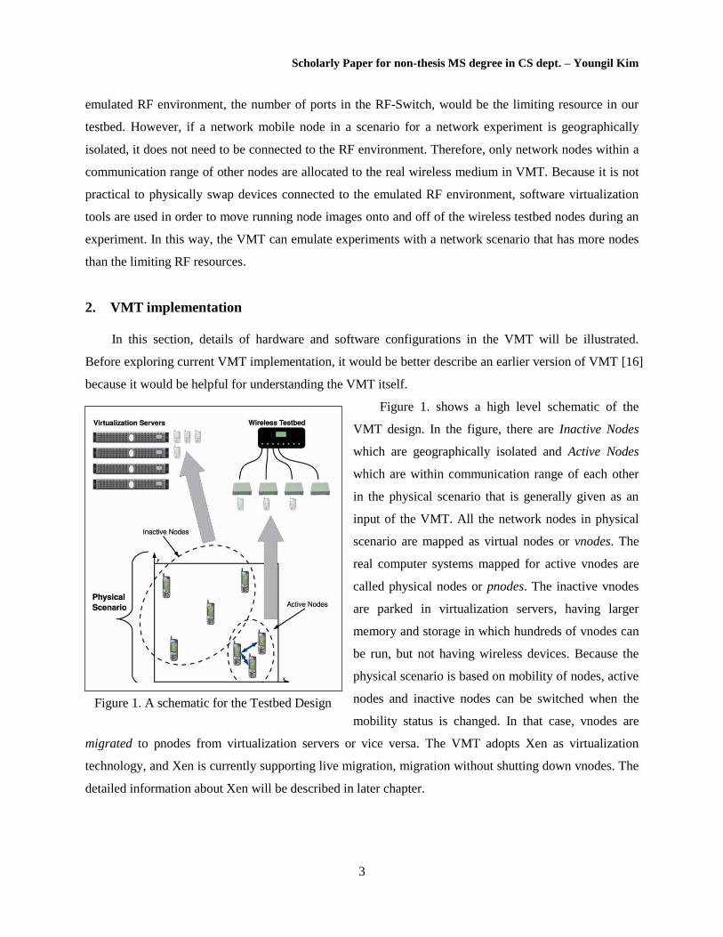
Figure 1. shows a high level schematic of the
VMT design. In the figure, there are Inactive Nodes
which are geographically isolated and Active Nodes
which are within communication range of each other
in the physical scenario that is generally given as an
input of the VMT. All the network nodes in physical
scenario are mapped as virtual nodes or vnodes. The
real computer systems mapped for active vnodes are
called physical nodes or pnodes. The inactive vnodes
are parked in virtualization servers, having larger
memory and storage in which hundreds of vnodes can
be run, but not having wireless devices. Because the
physical scenario is based on mobility of nodes, active
nodes and inactive nodes can be switched when the
mobility status is changed. In that case, vnodes are
migrated to pnodes from virtualization servers or vice versa. The VMT adopts Xen as virtualization
technology, and Xen is currently supporting live migration, migration without shutting down vnodes. The
detailed information about Xen will be described in later chapter.
Figure 1. A schematic for the Testbed Design

Scholarly Paper for non-thesis MS degree in CS dept. – Youngil Kim
4
2.1. Architecture of VMT
Figure 2. shows the overview of the VMT system, and the testbed architecture consists of three main
components:
An RF matrix switch and a collection of wireless devices which host vnodes which are within
communication range of other nodes
Rack-mount servers that host isolated vnodes
A mobility/migration management system that moves vnode images between these two physical
entities and manipulates attenuation settings within the RF switch based on the underlying
physical scenario
The hardware setup consists of two JFW 50PA-338 8-port RF matrix switches, multiple Dell Studio
Hybrid computers, an AOE server, and a virtualization server – all connected through a gigabit Ethernet
switch. The AOE server and virtualization servers are Penguin Relion 1600SC machines. Each Studio
Hybrid is equipped with a Broadcom BCM4321 802.11 a/b/g card with a Mini PCI Express as host
interface and Windows driver, using a frequency band of 2.4 GHz and 5 GHz. The Studio Hybrids are
similar to Dell Studio-series laptops, but they are repackaged as a small form-factor desktop which allows
them to fit into our shielded enclosures; they support Gigabit Ethernet and MiniPCI express Wi-Fi cards;
they are available with a reasonably capable processor that supports Intel VT (Intel Core 2 Duo T8100).
Figure 2. Virtual Mesh Testbed (VMT) System Architecture
Scholarly Paper for non-thesis MS degree in CS dept. – Youngil Kim
5
The wireless testbed part consists of computers in shielded enclosures, two RF matrix switches, and
a switch control server. The RF energy from each computer's Wi-Fi card is cabled out of the enclosures
and into the matrix switch of programmable attenuators. The enclosures prevent inadvertent cross-talk,
and the RF switch allows us to arbitrarily control the attenuation between the wireless devices.
The program that controls the RF switch at the heart of the Virtual MeshTest system is a daemon,
called xsimd. The xsimd daemon was developed for the MeshTest testbed efforts at LTS [8], and is used
with some modifications in the current VMT implementation. The daemon accepts physical scenarios
from the mobility management system, computes the appropriate attenuator settings, and applies them to
the RF matrix switch. Physical scenarios consist of an XML-encoded list of node locations. By repeatedly
sending physical scenarios to xsimd at regular intervals, the wireless testbed can subject the devices
connected to RF-Switches to the simulated effects of mobility.
2.2. Developing virtualization using Xen As it is described in the previous chapter, the core idea for the VMT is based on node virtualization
and migration. However there are many virtualization technologies, the VMT selected Xen because of its
flexibility of accommodating OS of virtual nodes independent to the host system and its relatively wide
adoption.
The Xen is a paravirtualization technology for several architectures that provides a hardware
abstraction similar but not identical to the raw hardware through its Virtual Machine Monitor (VMM)
called a hypervisor. The modified guest OS called domains run on top of the hypervisor. In contrast,
OpenVZ is an OS-level virtualization technology for Linux kernels. While some users have found it to
have better performance than the Xen [17], the restriction of not being able to run different guest OS gave
us a strong disincentive to adopt it for our experiments.
Using wireless interfaces from within the Xen virtual machines presented some challenges. The Xen
provides primarily three network configurations which are bridging mode, routing mode, and NAT mode.
NAT mode was not considered because the node's IP address is not visible to external networks and it is
not appropriate for the experiments.
Each virtual machine can have logical network interfaces. The MAC addresses of the logical
interfaces can be either manually assigned or randomly generated. In bridging mode, the MAC address of
the logical interface is visible to external networks. In routing mode, the IP address of the logical interface
is visible to external networks. The Xen also creates virtual network interface (vif) which is a pair of
connected virtual Ethernet interfaces with one end in guest OS (also called domainU) and the other in
host OS (also called domain0).

Scholarly Paper for non-thesis MS degree in CS dept. – Youngil Kim
6
Figure 3. shows the difference between Xen bridging mode and routing mode. The bridging mode is
chosen in the current implementation because common DTN neighbor discovery techniques are simpler if
nodes are in the same MAC broadcast domain. In addition, default gateway should be ip address of
domain0 in routing mode even though domain0 is changed when vnodes are migrated among pnodes. So,
it would be difficult to manage stable network configurations. There was also a problem using bridging
mode caused by difference between characteristics of wireless and wired network protocol. A
complication with the Xen and wireless interface in bridge mode is that ACKs, from destination vnode
routed to the source vnode, can be rejected at the host interface (interface of domain0) of the source
vnode because the Xen recognizes it as the wrong MAC address. Utilizing a Linux tool called ebtables to
translate MAC addresses makes the bridge mode work with the wireless interface. Basically in this set-up,
the source and destination addresses of the MPDUs over the air are the MAC addresses assigned to the
802.11 physical interfaces. On the source side, the MAC addresses of the interfaces on the virtual
machines are translated to the physical addresses before they reach the wireless physical interface. On the
destination side, the MAC address of the destination is translated to the address of the virtual machine's
interface before it reaches the bridge.
2.3. VMT Controller: Mobility Management Software The software components in our testbed which control node movement and migration are also shown
in Figure 2. The system takes a set of parameters describing a physical mobility scenario as input. For
example, the system was tested with mobility patterns for the DataMULE and several variants of random
direction Mini-Beltway, and three node drive-by deterministic models. The Scenario Generator produces
an XML file encoding the desired mobile scenario, which is used by the VMTController to determine
Figure 3. Xen Bridging mode vs. Routing mode [18]

Scholarly Paper for non-thesis MS degree in CS dept. – Youngil Kim
7
what and when node migrations should take place, and encodes what physical scenarios should be sent to
the xsimd daemons. This last step can get somewhat convoluted because the mapping between nodes in
the original scenario and switch inputs changes throughout an experiment. An experiment is started by
invoking the VMTController. The VMTController maintains real time during the experiment, sending
physical scenarios to xsimd and issuing Xen commands to the pnodes.
The XML file generated from the scenario generator is used as input to execute the migration
commands which move vnodes from either the Hybrids (pnode systems) or the Penguin server
(virtualization server). The controller also sends the current physical scenario to xsimd every second.
When a vnode migrates from the virtualization server to a pnode, the corresponding attenuation settings
between it and the nodes in range of should be updated as soon as the migration is complete. The issuing
of xsimd commands is fairly straightforward, but the procedure for migrating vnodes can become
somewhat complicated.
2.4. Migration Algorithms Two primary migration algorithms are implemented in the current VMTController. The first
algorithm called Depth First Search-range (DFS-D) uses a single-linkage clustering algorithm, similar to
a depth-first search, to group nodes into clusters. When two nodes are within some distance D, called the
migration range, of each other in the physical scenario, the VMTController must assign them to the same
RF-switch. If a node is more than distance D from all other nodes it is considered isolated, and is
scheduled to be migrated to the offline virtualization server. If a given mobility scenario has
communicating clusters that require more resources than are available (more switches, or more ports on a
given switch), the VMTController will reject the migration of the corresponding node or nodes.
In addition, a second algorithm named Shortest Link First was implemented with intension to
allocate as many as possible virtual nodes to physical nodes and the brief description is followed.
1 Make a sorted list of inter-node distances.
2 Iterate through the pairs of nodes in the sorted.
2.1 If the 2 nodes are not already allocated to a switch, allocate them to the same switch. If
there is no switch having more than 2 available ports, the nodes cannot be allocated.
2.2 If 1 node is already allocated, try to allocate the other node to the same switch, if there is
no room in the switch, the node cannot be allocated.
3 To minimize migration, try to allocate nodes to switch ports where it was allocated previously.

Scholarly Paper for non-thesis MS degree in CS dept. – Youngil Kim
8
The SLF algorithm is designed to allocate as many virtual nodes as possible to physical nodes.
Unlike DFS, the SLF algorithm does not have a hard boundary at which migrations must take place.
Therefore the behavior does not change even when the wireless range of emulated wireless system is
changed. In other words, the SLF algorithm maximizes the utilization of physical nodes based on number
of available RF-Switch ports.
3. Experiments with DOME Traces
In this section, we investigate using DOME traces on our testbed. DOME, which stands for Diverse
Outdoor Mobile Environment, is a testbed meant for large-scale mobile experiments consisting of buses
equipped with a Linux box, a WiFi radio, a GPS unit, and a long-range, low bandwidth 900 MHz Xtend
radio [19]. The data collected from the DOME testbed over a period of four years is available through the
CRAWDAD website [20]. In this paper, the trace collected in the months of October to November 2007
is used. In particular, following two traces are used:
gps_logs: These logs contain time stamped GPS locations for every bus and for each day during
the collection period.
mobile-mobile: This trace contains mobile-mobile contact events for each day during the
collection period. Each line in the trace includes the time at which a contact occurred, the amount
of data that was transferred, the duration of contact and the position where the contact occurred.
3.1. Creating Mobility Scenario
The mobile-mobile trace gives the location of the
contact, but another means of computing the mobility
routes for the buses is needed. GPS parser program is
implemented for producing that mobility scenario
with xml format based on the GPS information of
buses in the gps_logs. This scenario is fed into the
VMTController and desired mobility scenario is
executed. Since the VMTController requires the
coordinate information for each node on a per second
basis, the gaps in GPS logs are filled with linearly
interpolated GPS coordinates. Figure 4. shows bus
routes for the trace data including some interpolated
sections.
Figure 4. DieselNet Bus Route
Scholarly Paper for non-thesis MS degree in CS dept. – Youngil Kim
9
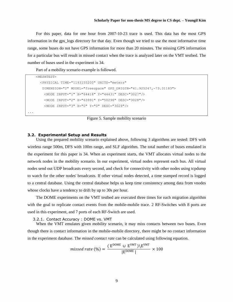
For this paper, data for one hour from 2007-10-23 trace is used. This data has the most GPS
information in the gps_logs directory for that day. Even though we tried to use the most informative time
range, some buses do not have GPS information for more than 20 minutes. The missing GPS information
for a particular bus will result in missed contact when the trace is analyzed later on the VMT testbed. The
number of buses used in the experiment is 34.
Part of a mobility scenario example is followed.
<MESHTEST>
<PHYSICAL TIME="1193155200" UNITS="meters"
DIMENSION="2" MODEL="freespace" GPS_ORIGIN="41.925247,-73.31183">
<NODE INPUT="1" X="64418" Y="44431" DESC="3027"/>
<NODE INPUT="2" X="63991" Y="50296" DESC="3028"/>
<NODE INPUT="3" X="0" Y="0" DESC="3029"/>
...
Figure 5. Sample mobility scenario
3.2. Experimental Setup and Results Using the prepared mobility scenario explained above, following 3 algorithms are tested: DFS with
wireless range 500m, DFS with 100m range, and SLF algorithm. The total number of buses emulated in
the experiment for this paper is 34. When an experiment starts, the VMT allocates virtual nodes to the
network nodes in the mobility scenario. In our experiment, virtual nodes represent each bus. All virtual
nodes send out UDP broadcasts every second, and check for connectivity with other nodes using tcpdump
to watch for the other nodes' broadcasts. If other virtual nodes detected, a time stamped record is logged
to a central database. Using the central database helps us keep time consistency among data from vnodes
whose clocks have a tendency to drift by up to 30s per hour.
The DOME experiments on the VMT testbed are executed three times for each migration algorithm
with the goal to replicate contact events from the mobile-mobile trace. 2 RF-Switches with 8 ports are
used in this experiment, and 7 ports of each RF-Switch are used.
3.2.1. Contact Accuracy : DOME vs. VMT When the VMT emulates given mobility scenario, it may miss contacts between two buses. Even
though there is contact information in the mobile-mobile directory, there might be no contact information
in the experiment database. The missed contact rate can be calculated using following equation.
𝑚𝑖𝑠𝑠𝑒𝑑 𝑟𝑎𝑡𝑒 % = ( EDOME ∪ EVMT )\EVMT
|EDOME | × 100
Scholarly Paper for non-thesis MS degree in CS dept. – Youngil Kim
10
EDOME
and EVMT
are respectively the sets of second pairs of nodes in contact for the DOME and the
VMT. For example a 10s encounter between two nodes in the VMT would correspond to 10 1-second
elements in the set EVMT
. The elements of the sets are triples (timestamp, node_1, node_2).
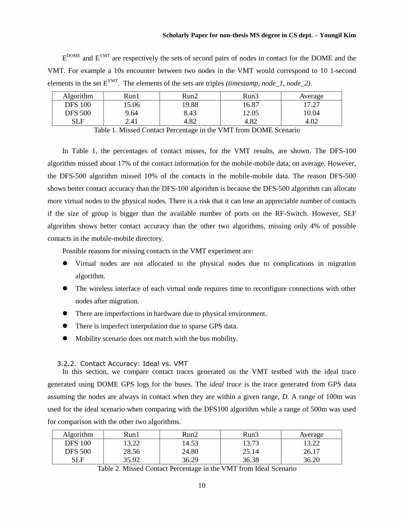
Algorithm Run1 Run2 Run3 Average
DFS 100 15.06 19.88 16.87 17.27
DFS 500 9.64 8.43 12.05 10.04
SLF 2.41 4.82 4.82 4.02
Table 1. Missed Contact Percentage in the VMT from DOME Scenario
In Table 1, the percentages of contact misses, for the VMT results, are shown. The DFS-100
algorithm missed about 17% of the contact information for the mobile-mobile data, on average. However,
the DFS-500 algorithm missed 10% of the contacts in the mobile-mobile data. The reason DFS-500
shows better contact accuracy than the DFS-100 algorithm is because the DFS-500 algorithm can allocate
more virtual nodes to the physical nodes. There is a risk that it can lose an appreciable number of contacts
if the size of group is bigger than the available number of ports on the RF-Switch. However, SLF
algorithm shows better contact accuracy than the other two algorithms, missing only 4% of possible
contacts in the mobile-mobile directory.
Possible reasons for missing contacts in the VMT experiment are:
Virtual nodes are not allocated to the physical nodes due to complications in migration
algorithm.
The wireless interface of each virtual node requires time to reconfigure connections with other
nodes after migration.
There are imperfections in hardware due to physical environment.
There is imperfect interpolation due to sparse GPS data.
Mobility scenario does not match with the bus mobility.
3.2.2. Contact Accuracy: Ideal vs. VMT In this section, we compare contact traces generated on the VMT testbed with the ideal trace
generated using DOME GPS logs for the buses. The ideal trace is the trace generated from GPS data
assuming the nodes are always in contact when they are within a given range, D. A range of 100m was
used for the ideal scenario when comparing with the DFS100 algorithm while a range of 500m was used
for comparison with the other two algorithms.
Algorithm Run1 Run2 Run3 Average
DFS 100 13.22 14.53 13.73 13.22
DFS 500 28.56 24.80 25.14 26.17
SLF 35.92 36.29 36.38 36.20
Table 2. Missed Contact Percentage in the VMT from Ideal Scenario
Scholarly Paper for non-thesis MS degree in CS dept. – Youngil Kim
11
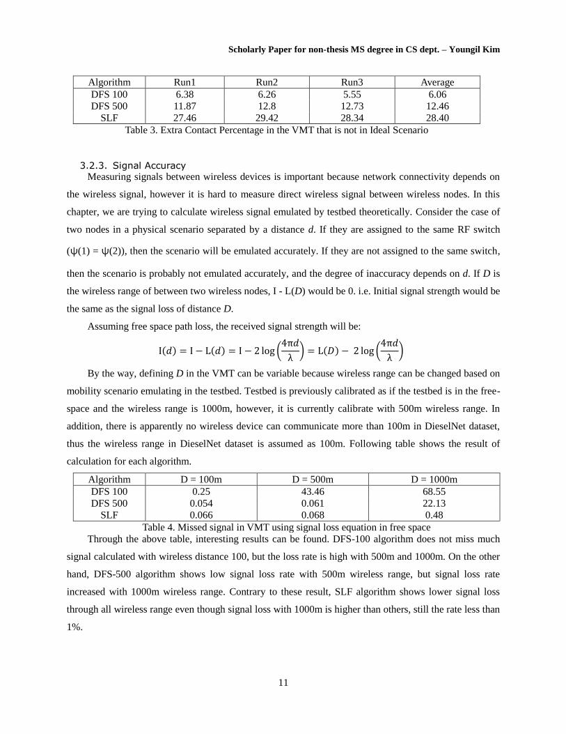
Algorithm Run1 Run2 Run3 Average
DFS 100 6.38 6.26 5.55 6.06
DFS 500 11.87 12.8 12.73 12.46
SLF 27.46 29.42 28.34 28.40
Table 3. Extra Contact Percentage in the VMT that is not in Ideal Scenario
3.2.3. Signal Accuracy Measuring signals between wireless devices is important because network connectivity depends on
the wireless signal, however it is hard to measure direct wireless signal between wireless nodes. In this
chapter, we are trying to calculate wireless signal emulated by testbed theoretically. Consider the case of
two nodes in a physical scenario separated by a distance d. If they are assigned to the same RF switch
(ψ(1) = ψ(2)), then the scenario will be emulated accurately. If they are not assigned to the same switch,
then the scenario is probably not emulated accurately, and the degree of inaccuracy depends on d. If D is
the wireless range of between two wireless nodes, I - L(D) would be 0. i.e. Initial signal strength would be
the same as the signal loss of distance D.
Assuming free space path loss, the received signal strength will be:
I 𝑑 = I − L 𝑑 = I − 2 log 4π𝑑
λ = L 𝐷 − 2 log
4π𝑑
λ
By the way, defining D in the VMT can be variable because wireless range can be changed based on
mobility scenario emulating in the testbed. Testbed is previously calibrated as if the testbed is in the free-
space and the wireless range is 1000m, however, it is currently calibrate with 500m wireless range. In
addition, there is apparently no wireless device can communicate more than 100m in DieselNet dataset,
thus the wireless range in DieselNet dataset is assumed as 100m. Following table shows the result of
calculation for each algorithm.
Algorithm D = 100m D = 500m D = 1000m
DFS 100 0.25 43.46 68.55
DFS 500 0.054 0.061 22.13
SLF 0.066 0.068 0.48
Table 4. Missed signal in VMT using signal loss equation in free space
Through the above table, interesting results can be found. DFS-100 algorithm does not miss much
signal calculated with wireless distance 100, but the loss rate is high with 500m and 1000m. On the other
hand, DFS-500 algorithm shows low signal loss rate with 500m wireless range, but signal loss rate
increased with 1000m wireless range. Contrary to these result, SLF algorithm shows lower signal loss
through all wireless range even though signal loss with 1000m is higher than others, still the rate less than
1%.

Scholarly Paper for non-thesis MS degree in CS dept. – Youngil Kim
12
One of the reasons why SLF shows this good signal loss rate is the number of buses communicating
simultaneously is less than the available number of ports in RF-Switches. If there are number of nodes
more than the available number of ports in RF-Switches, the signal loss would be increased more highly
than the previous result.
3.2.4. Time gap between VMT and Ideal scenario The last property to check is time gap which means the difference in total time for execution
between given mobility scenario and the VMT emulation. For example, the duration of mobility scenario
used in this paper is one hour scenario. However total execution time for running the scenario is one hour
and 820 seconds for the first execution with DFS-100 algorithm. This time gap is mostly caused by the
time of migration. In current Xen technology, it takes 2 seconds at least for migrating from one physical
node to the other physical node. If these time gaps would not be handled, the testbed could need much
more time than given scenario. In addition, real-time emulation could not be executable. In order to avoid
too massive time gaps, several techniques are designed and implemented as following.
Migration Queue: Implemented Xen migration handler running as a thread communicating with
main thread through a shared queue containing migration information. So, main thread can continue
without waiting end of migration.
Xen sole server: Designed new server system only responsible for virtualization while main server
concentrates on calculating migration and managing central database.
Adopting XML RPC: Changed ssh command based Xen communication with XML RPC. XML
RPC is lighter than SSH protocol.
Even though above techniques are applied to solve the time gap problem, there are still some time
gaps, and Table 5 shows the data.
Algorithm Run1 Run2 Run3 Average
DFS 100 820 822 816 819
DFS 500 1742 1747 1764 1751
SLF 644 640 642 642
Table 5. Time gaps between VMT and Ideal Scenario (sec)
In the result table, DFS-100 algorithm shows less time gaps than DFS-500 algorithm. However,
DFS-100 shows less contact accuracy than DFS-500 in the previous comparison. Thus, it seems to me
that DFS-100 allocated less virtual nodes to physical nodes than DFS-500, so there was less migration
than DFS-500. the SLF algorithm shows more less time gaps than other algorithms even though it
allocates more virtual nodes than other algorithm. It means the node length table would not change
frequently in this DieselNet scenario, and the SLF algorithm is the most efficient algorithm among 3
algorithms.
Scholarly Paper for non-thesis MS degree in CS dept. – Youngil Kim
13
4. Conclusion and Future Work
This paper provides a summary of the current state of the VMT system, and results from
experiments based on real encounter traces. The results demonstrate the power of VMT to easily and
reproducibly run experiments using a diverse variety of real trace-based scenarios. However they also
highlight some of the challenges and limitations of the system. Though the testbed is now being actively
used for real Delay-Tolerant Network experiments, development of the system is continued. Issues
highlighted in this paper include:
Migration algorithms: In order to efficiently run experiments with larger numbers of nodes,
inefficiencies with the current DFS-D migration algorithm is observed. The SLF algorithm is a
first step in that direction.
Channel and terrain modeling: Using our default channel model, our DieselNet encounter
results were far more optimistic than the actual DieselNet traces turn out to be. Making this
aspect of the experiments more realistic involves modeling of terrain and urban areas, and more
advanced channel modeling.
Experiment management: Setting up experiments on the current system requires considerable
knowledge of the internals of the system. Using Emulab to control VMT experiments is
underway. This will facilitate our eventual goal of opening the system to external researchers.
Thanks to the VMT Team, Padma Mundur, Brenton Walker, Carson Dunbar and Keith Taylor, who
contributed ideas, discussion and hardware configuration to the VMT system.
5. References
[1] Libo Song, David F. Kotz, Evaluating opportunistic routing protocols with large realistic contact
traces In CHANTS 2007 ( 2007)
[2] Scott, J., Gass, R., Crowcroft, J., Hui, P.,Diot, C., and Chaintreau, A.
CRAWDAD trace set cam-bridge/haggle/imote (v. 2009-05-29). Downloaded from
http://crawdad.cs.dartmouth.edu/cambridge/haggle/imote, May 2009.
[3] Piorkowski, M., Sarafijanovic-Djukic, N., and Grossglauser, M. CRAWDAD data set ep /mobility
(v. 2009-02-24). Downloaded from http://crawdad.cs.dartmouth.edu/ep/mobility, Feb.2009
[4] The Network Simulator NS-2. http://www.isi.edu/nsnam/ns/.
[5] Keränen, A., Ott, J., and K•arkk•ainen, T. The one simulator for dtn protocol evaluation. In

Scholarly Paper for non-thesis MS degree in CS dept. – Youngil Kim
14
Simutools '09 (2009), ICST, pp. 1-10.
[6] Demmer, M., Du, B., and Brewer, E. Tierstore: adistributed lesystem for challenged networks in
developing regions. In FAST'08 (2008), USENIX Association, pp. 1-14.
[7] Seastrom, J. Characterizing transport layer behavior in the meshtest wireless testbed. Master's
thesis,
University of Maryland-College Park, 2008.
[8] Clancy, T. C., and Walker, B. D. Meshtest: Laboratory-based wireless testbed for large topologies.
In IEEE TridentCom 2007 (2007), pp. 1-6.
[9] Judd, G., and Steenkiste, P. Repeatable and realistic wireless experimentation through physical
emulation. SIGCOMM Comput. Commun. Rev. 34, 1 (2004), 63-68.
[10] Carnegie Mellon University Wireless Emulator. http://www.cs.cmu.edu/~emulator/.
[11] Mike Hibler, Robert Ricci, Leigh Stoller, Jonathan Duerig, Shashi Gururorasad, Tim Stack, Kirk
Webb and Jay Lapreau, Large-scale Visualization in the Emulab Network Testbed, Usenix, 2008.
[12] Steffen Maier, Daniel Herrscher, Kurt Rothermel, Storage Routing for DTN Congestion Control,
Computer Communications, vol. 30, 2007, 943-956.
[13] L. Romero Amondaray, J. Seoane Pascual, Delay Tolerant Network Simulation with vnuml, ACM
CHANTS, 2008.
[14] Gregory Smith, Anmol Chaturvedi, Arunesh Mishra, Suman Banergee, Wireless Virtualization on
Commodity 802.11 Hardware, WINTECH, 2007.
[15] Gautam Bhanage, Ivan Seskar, Yanyong Zhang, Dipankar Raychau dhuri, Evaluation of OpenVZ
Based Wireless Testbed Virtualization, Rutgers University, 2008, WINLAB-TR-331.
[16] Hahn, D., Lee, G., Walker, B., Beecher, M., Mundur, P. Using virtualization and live migration in
a scalable mobile wireless testbed. SIGMETRICS Perform. Eval. Rev. 38 (January 2011), 21-25.
[17] Pradeep Padala, Xiaoyun Zhu, Zhikui Wang, Sharad Singhal, Kang G. Shin, Performance
Evaluation of Virtualization Technologies for Server Consolidation, HP Laboratories, 2008, HPL-
2007-59R1.
[18] Zach Shepherd and Wenjin Hu, Introduction to the Open Source Xen Hypervisor, Clarkson
University, 2009.
[19] Banerjee, N., Corner, M. D., Towsley, D., and Levine, B. N. Relays, base stations, and meshes:
Enhancing mobile networks with infrastructure. In ACM MobiCom (2008).
[20] Dieselnet traces. http://crawdad.cs.dartmouth.edu/meta.php?name=umass/diesel.