Embed Size (px)
Citation preview
School of Computer Science G51CSA
1
Computer Systems Architecture
Fundamentals Of Digital Logic

School of Computer Science G51CSA
2
Our Goal
Understand
Fundamentals and basics concepts How computers work at the lowest level
Avoid whenever possible
Complexity Implementation details Engineering design rules
School of Computer Science G51CSA
3
Electrical Terminology
Voltage Quantifiable property of electricity Measure of potential force Unit of measure: volt
Current Quantifiable property of electricity Measure of electron flow along a path Unit of measure: ampere (amp)
School of Computer Science G51CSA
4
Analog For Electricity
Voltage is analogous to water pressure
Current is analogous to flow of water
Can have
High pressure with little flow Large flow with little pressure
School of Computer Science G51CSA
5
Voltage
Device used to measure called voltmeter
Can only be measured as difference between two points
To measure voltage
Assume one point represents zero volts (known as ground)
Express voltage of second point wrt ground

School of Computer Science G51CSA
6
In Practice
Typical digital circuit operates on five volts
Two wires connect each chip to power supply
Ground (zero volts) Power (five volts)
Digital logic diagrams do not usually show power and ground connections
School of Computer Science G51CSA
7
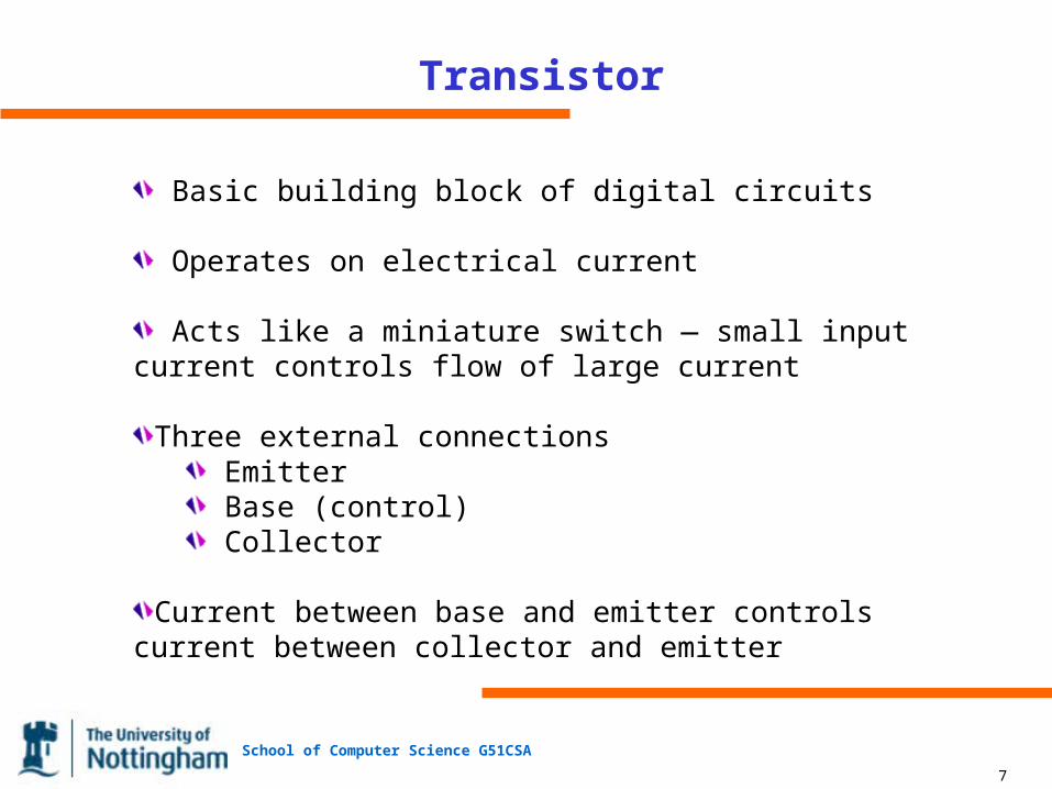
Transistor
Basic building block of digital circuits
Operates on electrical current
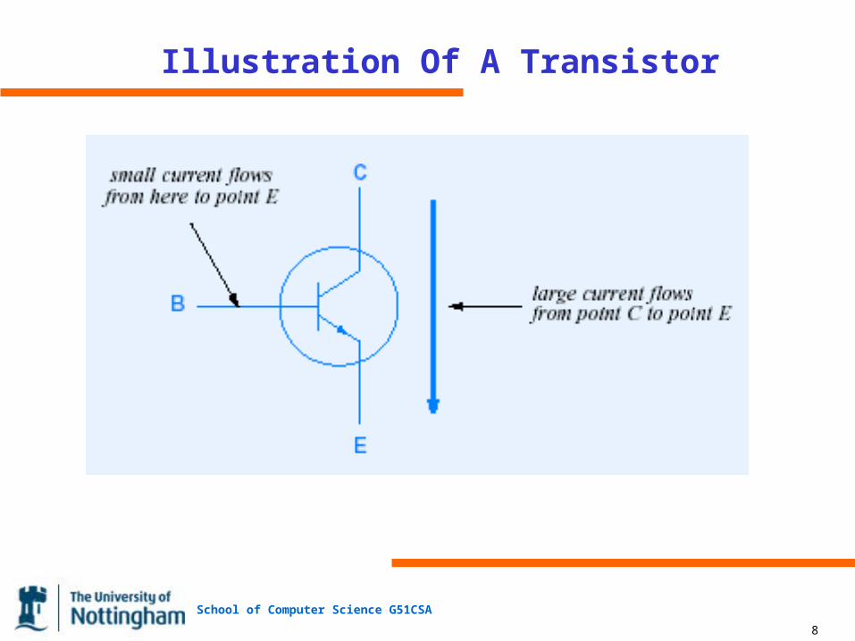
Acts like a miniature switch — small input current controls flow of large current
Three external connections Emitter Base (control) Collector
Current between base and emitter controls current between collector and emitter
School of Computer Science G51CSA
8
Illustration Of A Transistor

School of Computer Science G51CSA
9
Boolean Logic
Mathematical basis for digital circuits
Three basic functions: and, or, and not
School of Computer Science G51CSA
10
Digital Logic
Can implement Boolean functions with transistors
Five volts represents Boolean 1
Zero volts represents Boolean 0
School of Computer Science G51CSA
11
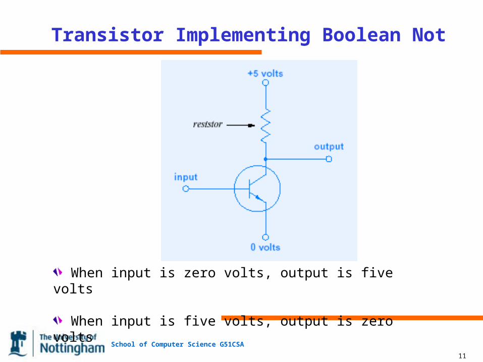
Transistor Implementing Boolean Not
When input is zero volts, output is five volts
When input is five volts, output is zero volts
School of Computer Science G51CSA
12
Logic Gate
Hardware component
Consists of integrated circuit
Implements an individual Boolean function
To reduce complexity, provide inverse of Boolean functions
Nand gate implements not and Nor gate implements not or Inverter implements not
School of Computer Science G51CSA
13
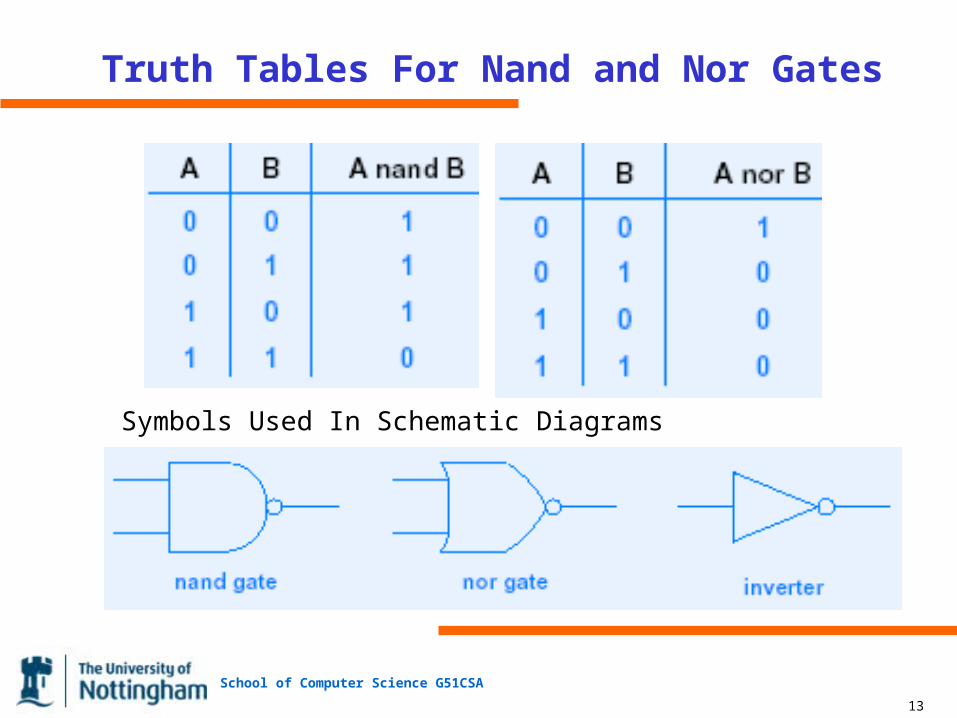
Truth Tables For Nand and Nor Gates
Symbols Used In Schematic Diagrams
School of Computer Science G51CSA
14
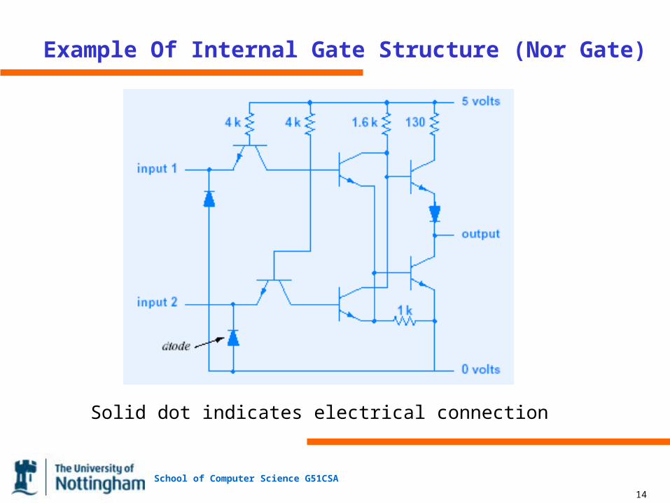
Example Of Internal Gate Structure (Nor Gate)
Solid dot indicates electrical connection

School of Computer Science G51CSA
15
Technology For Logic gates
Most popular technology known as Transistor-Transistor Logic (TTL)
Allows direct interconnection (a wire can connect output from one gate to input of another)
Single output can connect to multiple inputs
Called fanout Limited to a small number
School of Computer Science G51CSA
16
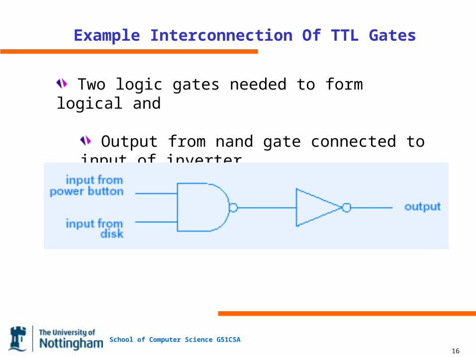
Example Interconnection Of TTL Gates
Two logic gates needed to form logical and
Output from nand gate connected to input of inverter
School of Computer Science G51CSA
17
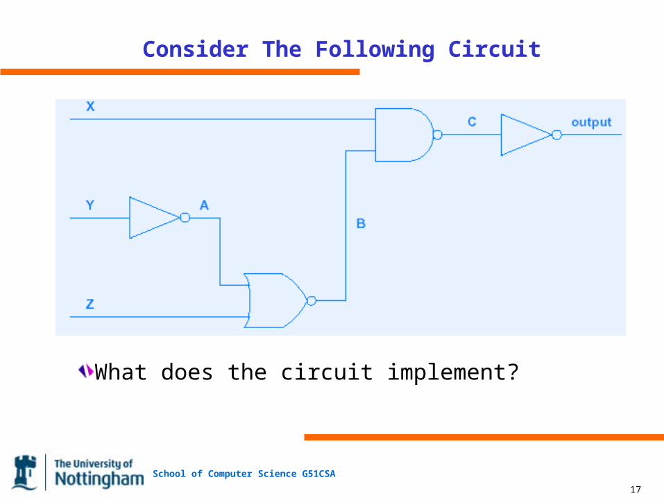
Consider The Following Circuit
What does the circuit implement?
School of Computer Science G51CSA
18
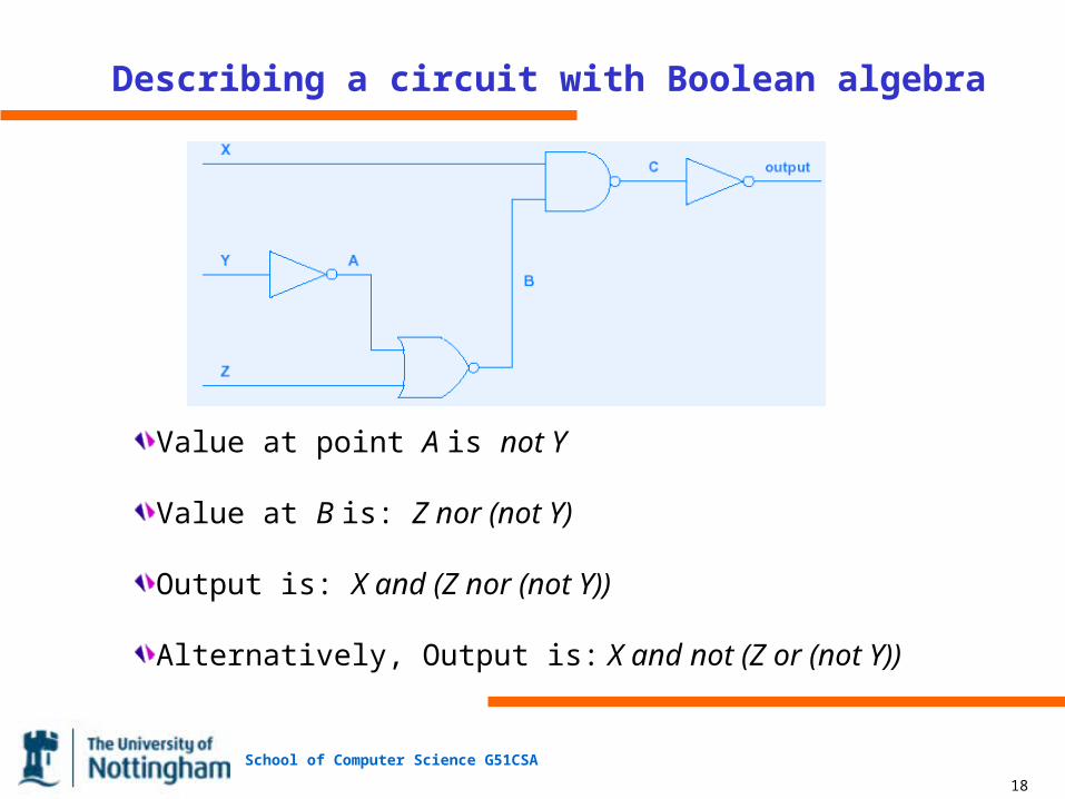
Describing a circuit with Boolean algebra
Value at point A is not Y
Value at B is: Z nor (not Y)
Output is: X and (Z nor (not Y))
Alternatively, Output is: X and not (Z or (not Y))
School of Computer Science G51CSA
19
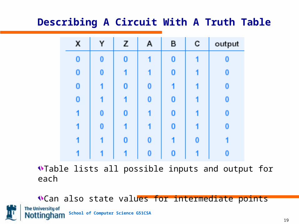
Describing A Circuit With A Truth Table
Table lists all possible inputs and output for each
Can also state values for intermediate points
School of Computer Science G51CSA
20
Avoiding Nand / Nor Operations
Circuits use nand and nor gates
Sometimes easier for humans to use and and or operations
Example circuit or truth table output can be described by Boolean expression:
X and Y and (not Z))
School of Computer Science G51CSA
21
In Practice
Only a few connections needed per gate
Chip has many pins for external connections
Result: can package multiple gates placed on each chip
School of Computer Science G51CSA
22
Example Of Logic Gates
7400 family of chips
Package is about one-half inch long
Implement TTL logic
Powered by five volts
Contain multiple gates per chip

School of Computer Science G51CSA
23
Examples Of Gates On 7400-Series Chips
Pins 7 and 14 connect to ground and power
School of Computer Science G51CSA
24
Circuits That Maintain State
More sophisticated than combinatorial circuits
Output depends on history of previous input as well as values on input lines
School of Computer Science G51CSA
25
Example Of Circuit That Maintains State
Basic flip-flop
Analogous to push-button power switch
Each new 1 received as input causes output to reverse
First input pulse to causes flip-flop to turn on
Second pulse causes flip-flop to turn off
School of Computer Science G51CSA
26
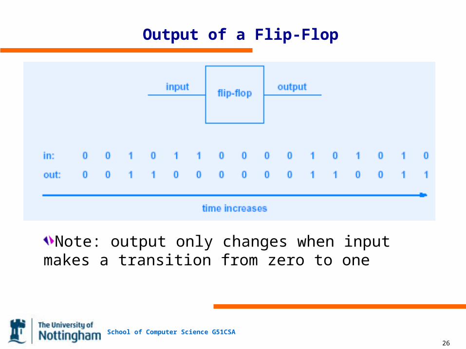
Output of a Flip-Flop
Note: output only changes when input makes a transition from zero to one
School of Computer Science G51CSA
27
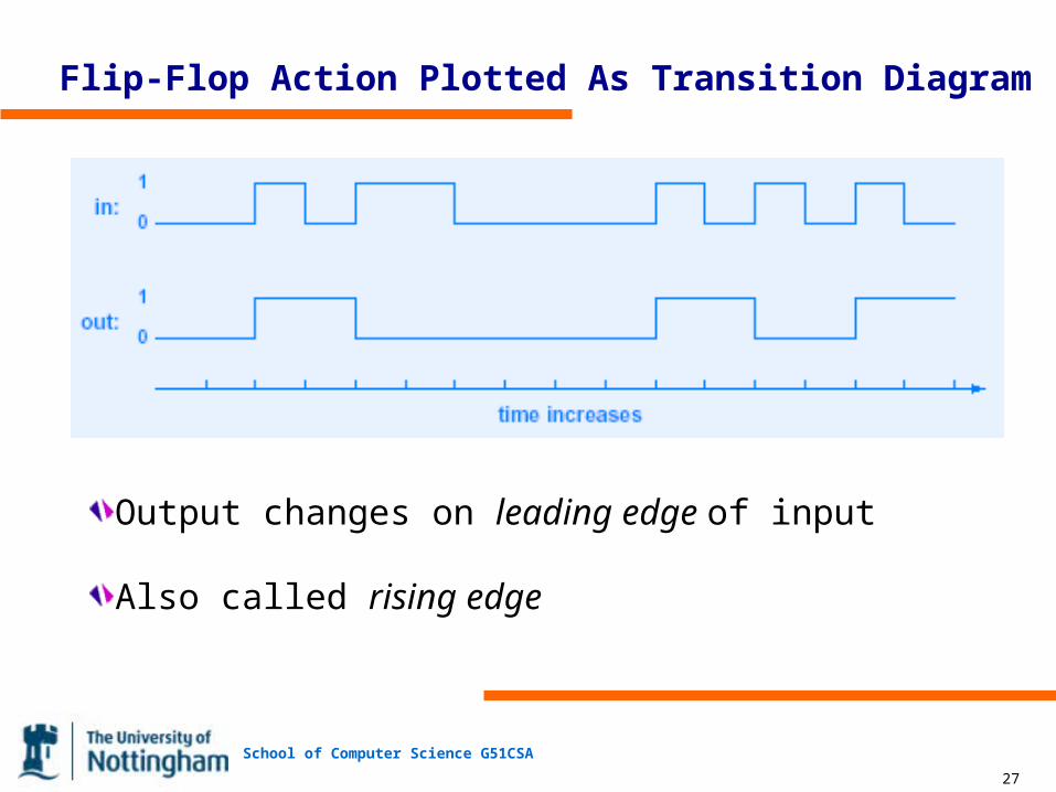
Flip-Flop Action Plotted As Transition Diagram
Output changes on leading edge of input
Also called rising edge
School of Computer Science G51CSA
28
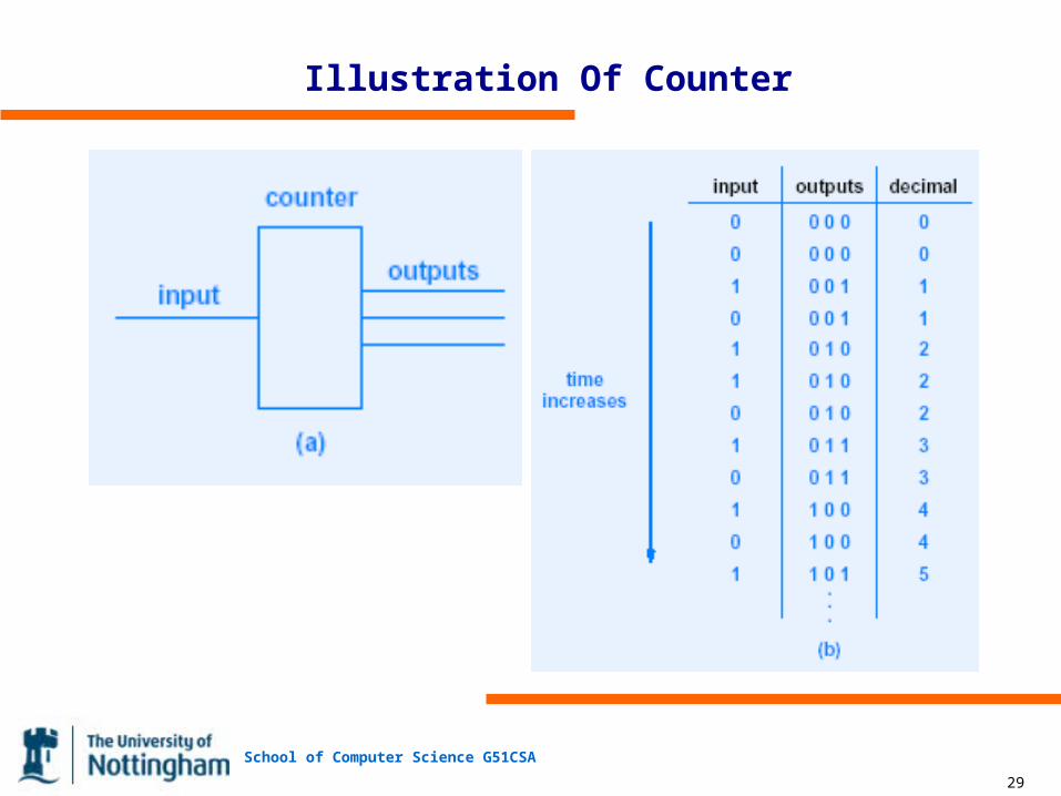
Binary Counter
Counts input pulses
Output is binary value
Includes reset line to start count at zero
Example: 4-bit counter available as single integrated circuit
School of Computer Science G51CSA
29
Illustration Of Counter
School of Computer Science G51CSA
30
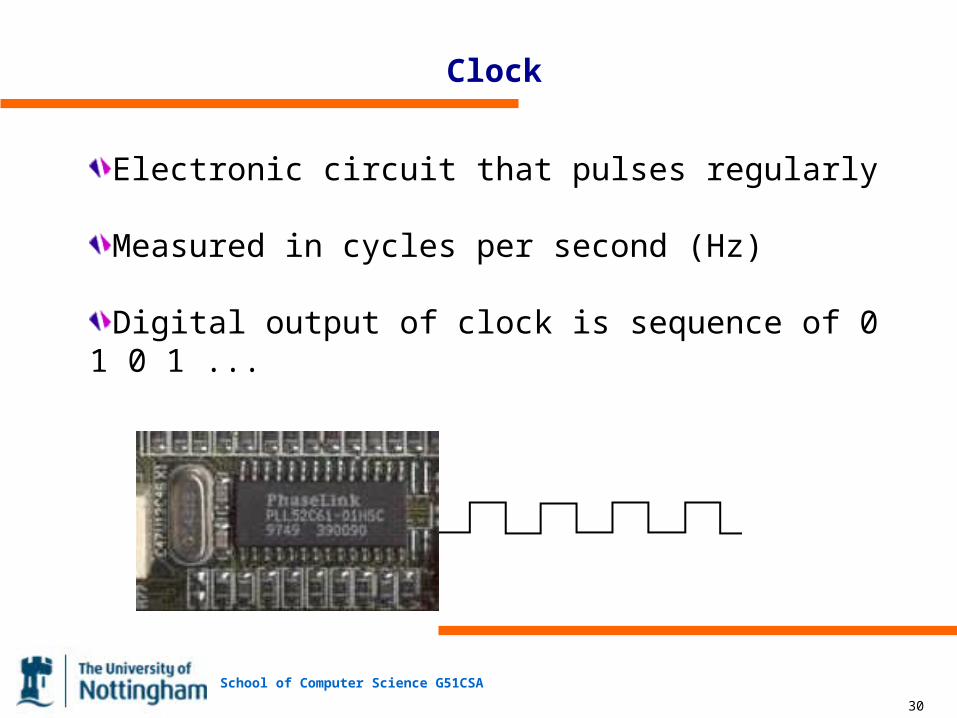
Clock
Electronic circuit that pulses regularly
Measured in cycles per second (Hz)
Digital output of clock is sequence of 0 1 0 1 ...
School of Computer Science G51CSA
31
Multiplexers
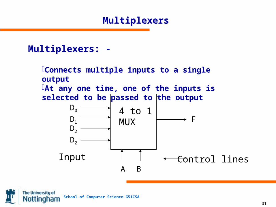
Multiplexers: -
Connects multiple inputs to a single outputAt any one time, one of the inputs is selected to be passed to the output
4 to 1MUX
D0
D1
D2
D2
A B
F
Input Control lines

School of Computer Science G51CSA
32
Multiplexers
Multiplexers: - Truth Table and Implementation
School of Computer Science G51CSA
33
Multiplexers
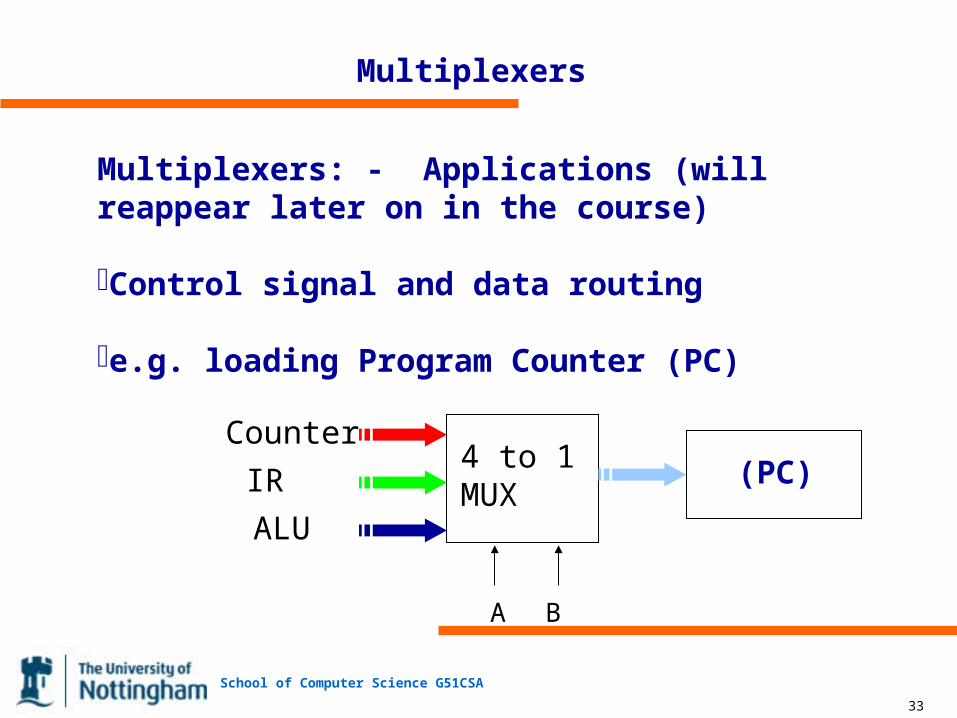
Multiplexers: - Applications (will reappear later on in the course)
Control signal and data routing
e.g. loading Program Counter (PC)
4 to 1MUX
A B
Counter
IR
ALU
(PC)
School of Computer Science G51CSA
34
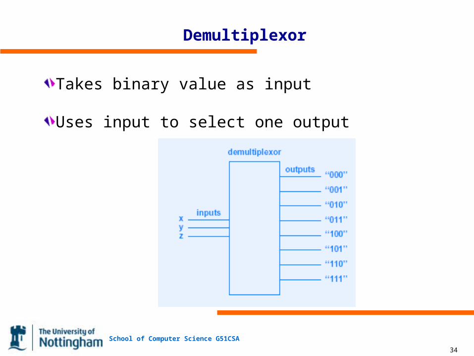
Demultiplexor
Takes binary value as input
Uses input to select one output
School of Computer Science G51CSA
35
Decoder
Decoders: - takes n inputs, and select exactly one of the 2n outputs
Example: 3 - 8 decoder

School of Computer Science G51CSA
36
Address Decoder
Decoders: - Address Decoder (will be revisited)
School of Computer Science G51CSA
37
Adder
Adders: - an essential part of the CPU
Half Adder
Truth Table Circuit
A B Sum Carry-Out
School of Computer Science G51CSA
38
Adder
Adders: - an essential part of the CPU
Full Adder
Truth Table
A B Carry-In Sum Carry-Out
School of Computer Science G51CSA
39
Adder
Adders: - n-bit adder
School of Computer Science G51CSA
40
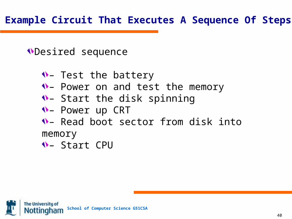
Example Circuit That Executes A Sequence Of Steps
Desired sequence
– Test the battery– Power on and test the memory– Start the disk spinning– Power up CRT– Read boot sector from disk into memory– Start CPU
School of Computer Science G51CSA
41
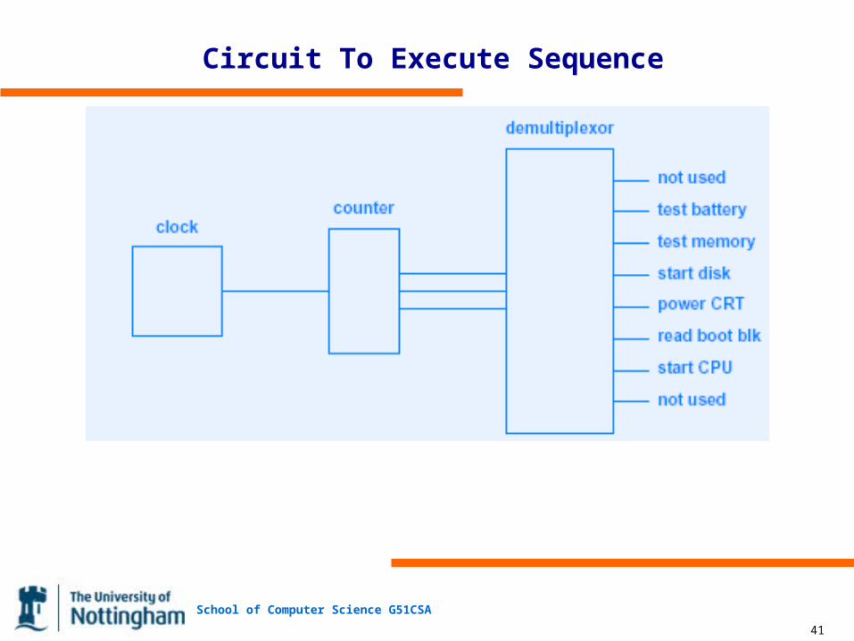
Circuit To Execute Sequence

School of Computer Science G51CSA
42
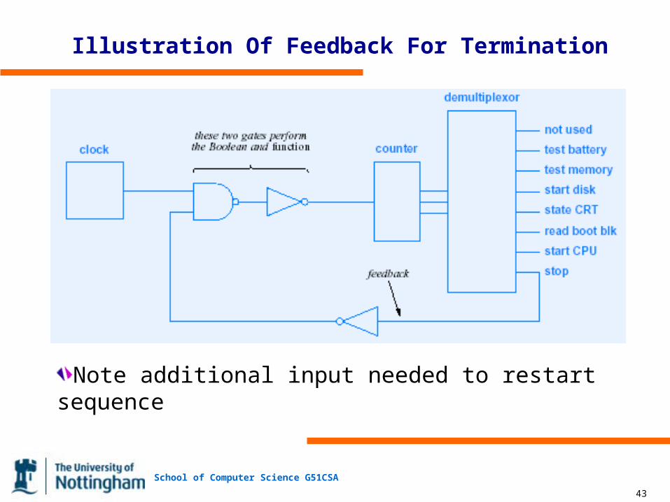
Feedback
Output of circuit used as an input
Allows more control
Example: stop sequence when output F becomes active
Boolean algebra
CLOCK and (not F)
School of Computer Science G51CSA
43
Illustration Of Feedback For Termination
Note additional input needed to restart sequence
School of Computer Science G51CSA
44
Practical Engineering Concerns
Power consumption (wiring must carry sufficient power)
Heat dissipation (chips must be kept cool)
Timing (gates take time to settle after input changes)
Clock synchronization (clock signal must reach all chips simultaneously)
School of Computer Science G51CSA
45
Summary
Computer systems are constructed of digital logic circuits
Fundamental building block is gate
Digital circuit can be described by– Boolean algebra (most useful when designing)– Truth table (most useful when debugging)
Clock allows active circuit to perform sequence of operations
Feedback allows output to control processing
Practical engineering concerns include– Power consumption and heat dissipation– Clock skew and synchronization