Embed Size (px)
Citation preview

Flame Extinguishing Intelligent System
March 11, 2010
Dr. Andrew Rawicz
School of Engineering Science
Simon Fraser University
Burnaby, British columbia
V5A 1S6
Re: ENSC 440 Design Specifications for a Flame Extinginuishing Intelligent System
Dear Dr. Rawicz:
Enclosed is our document, “Desig
System”, which describes both high level and low level design specifications of our product.
Our Flame Extinginuishing Intelligent System (FlexiSys) product will be able to address current
inefficient methods of extinguishing flames. By utilizing motors, sensors, and algorithms,
FlexiSys will be able to detect and extinguish a flame, minimizing both fire and water damage to
any structure.
These design specifications include the physical, electrical
system, and the integration needed to complete our working model. Specific parts will be listed
and detailed in preparation for our production model. In addition, future possible designs will
be discussed as well.
If any there are any questions or concerns, please feel free to contact me
[email protected] or by phone at (604) 780
Sincerely,
Kelvin Ho
President and CEO
FlexiSys – Flame Extinguishing Intelligent System
Flame Extinguishing Intelligent System
Re: ENSC 440 Design Specifications for a Flame Extinginuishing Intelligent System
Enclosed is our document, “Design Specifications for a Flame Extinginuishing Intelligent
System”, which describes both high level and low level design specifications of our product.
Our Flame Extinginuishing Intelligent System (FlexiSys) product will be able to address current
ent methods of extinguishing flames. By utilizing motors, sensors, and algorithms,
FlexiSys will be able to detect and extinguish a flame, minimizing both fire and water damage to
These design specifications include the physical, electrical, and mechanical aspects of our
system, and the integration needed to complete our working model. Specific parts will be listed
and detailed in preparation for our production model. In addition, future possible designs will
here are any questions or concerns, please feel free to contact me by email at
or by phone at (604) 780-3392.
g Intelligent System
Re: ENSC 440 Design Specifications for a Flame Extinginuishing Intelligent System
n Specifications for a Flame Extinginuishing Intelligent
System”, which describes both high level and low level design specifications of our product.
Our Flame Extinginuishing Intelligent System (FlexiSys) product will be able to address current
ent methods of extinguishing flames. By utilizing motors, sensors, and algorithms,
FlexiSys will be able to detect and extinguish a flame, minimizing both fire and water damage to
, and mechanical aspects of our
system, and the integration needed to complete our working model. Specific parts will be listed
and detailed in preparation for our production model. In addition, future possible designs will
by email at ENSC440-

Flame Extinguishing Intelligent System
Design Specifications
For a Flame Extinguishing Intelligent System
Flame Extinguishing Intelligent System
Design Specifications
me Extinguishing Intelligent System
Project Team: Kelvin Ho
Ken Zheng
Peter Zheng
Luke Dang
Contact Person: Kelvin Ho
Submitted to: Dr. Andrew Rawicz –
Steve Whitmore – ENSC 305
School of Engineering Scien
Simon Fraser University
Issued date: March 11, 2010
Revision: 1.0
– ENSC 440
ENSC 305
School of Engineering Science
Simon Fraser University

Flame Extinguishing Intelligent System
ii Executive Summary | FlexiSys
Executive Summary
Sprinkler systems and other similar fire extinguishing systems
inability to correctly determine a flame, the inability to a
lastly, the inability to control the amount of extinguishing material. These factors lead to excess
water damage and failure to extinguish the flame.
These design specifications for our Flame Extinguishing Intelligent
descriptions for both the design and development of our product and the justification behind
our choices. These specifications
followed by detailed specification
electronic system design. In addition, we include detailed test plans to ensure the stability and
the robustness of our system.
The system overview section details
Included in this section are the physical properties, the mechanical build, and the electronics
involved in the system. Furthermore, the
detailed figures and critical information such
The electronic system design specifications will list the components such as the microcontroller,
the sensors, and motors. In addition, justification for the part choices will illustrate the depth
of research prior to the design of this system.
The working model is designed to be a proof
in buildings. Once the working model is complete, optimizations will be performed in both the
physical and electrical aspects of design. The production model will minimize the footprint
through contract manufacturing and costs will be reduced by bulk purchases from
manufacturers.
These design specifications were based on our functional requirement documentation:
Specification for a Flame Extinguishing Intelligent System
the specifications in this document will be updated accordingly as well. This
functional specification documentation
Flame Extinguishing Intelligent System
FlexiSys©
Sprinkler systems and other similar fire extinguishing systems all share three critical flaws: the
inability to correctly determine a flame, the inability to aim the extinguishing material, and
lastly, the inability to control the amount of extinguishing material. These factors lead to excess
water damage and failure to extinguish the flame.
These design specifications for our Flame Extinguishing Intelligent System will provide detailed
descriptions for both the design and development of our product and the justification behind
These specifications will explain the high level specifications of the entire system,
followed by detailed specifications for two of our major subsystem designs: the physical and
electronic system design. In addition, we include detailed test plans to ensure the stability and
The system overview section details several simple points regarding the overall c
Included in this section are the physical properties, the mechanical build, and the electronics
Furthermore, the physical and mechanical design section
and critical information such as the materials used and the structural integrity.
The electronic system design specifications will list the components such as the microcontroller,
motors. In addition, justification for the part choices will illustrate the depth
esearch prior to the design of this system.
The working model is designed to be a proof-of-concept model and will not be actually installed
in buildings. Once the working model is complete, optimizations will be performed in both the
al aspects of design. The production model will minimize the footprint
through contract manufacturing and costs will be reduced by bulk purchases from
These design specifications were based on our functional requirement documentation:
Specification for a Flame Extinguishing Intelligent System [1]. As we proceed with our designs,
document will be updated accordingly as well. This also
ification documentation.
all share three critical flaws: the
im the extinguishing material, and
lastly, the inability to control the amount of extinguishing material. These factors lead to excess
System will provide detailed
descriptions for both the design and development of our product and the justification behind
the high level specifications of the entire system,
s for two of our major subsystem designs: the physical and
electronic system design. In addition, we include detailed test plans to ensure the stability and
the overall components.
Included in this section are the physical properties, the mechanical build, and the electronics
design section provides
as the materials used and the structural integrity.
The electronic system design specifications will list the components such as the microcontroller,
motors. In addition, justification for the part choices will illustrate the depth
concept model and will not be actually installed
in buildings. Once the working model is complete, optimizations will be performed in both the
al aspects of design. The production model will minimize the footprint
through contract manufacturing and costs will be reduced by bulk purchases from
These design specifications were based on our functional requirement documentation: Function
we proceed with our designs,
also extends to our

Flame Extinguishing Intelligent System
Table of Contents
Executive Summary ................................
List of Figures ................................
List of Tables ................................
Acronyms ................................................................
Glossary ................................................................
1. Introduction ................................
1.1 Scope ................................
1.2 Intended Audience ................................
2. System Overview/Overall System Design
2.1 Physical Properties ................................
2.2 Power Supply ................................
2.3 Sensor placement ................................
3. Physical and Mechanical Design
3.1 The Base ................................
3.2 Casing ................................
3.3 C-shape Main Bracket ................................
3.4 Sensor stack ................................
3.5 Water Pipe ................................
3.6 Water gun casing ................................
4. Electronic System Design ................................
4.1 Microcontroller Design................................
4.2 System logic ................................
4.3 Thermal Sensors ................................
4.4 Serial data communication with the Arduino
4.5 Solenoid Water Valve ................................
4.6 Motor design ................................
4.6.1 Servo Motors ................................
4.6.2 DC Motors ................................
5. System Test Plan ................................
5.1 Unit Testing ................................
5.1.1 Sensor................................
5.1.2 Solenoid Valve ................................
5.1.3 Motors ................................
5.2 No Fire Scenario ................................
5.3 Fire scenario ................................
6. Conclusion ................................
References ................................................................
Flame Extinguishing Intelligent System
..........................................................................................................................
................................................................................................................................
................................................................................................................................
................................................................................................
................................................................................................
............................................................................................................................
................................................................................................................................
................................................................................................
System Overview/Overall System Design ................................................................
................................................................................................
................................................................................................
................................................................................................
Physical and Mechanical Design .............................................................................................
...........................................................................................................................
...............................................................................................................................
................................................................................................
................................................................................................
................................................................................................
................................................................................................
................................................................................................
................................................................................................
................................................................................................
................................................................................................
Serial data communication with the Arduino ................................................................
................................................................................................
................................................................................................
................................................................................................
................................................................................................
................................................................................................
................................................................................................
.............................................................................................................................
................................................................................................
............................................................................................................................
................................................................................................
................................................................................................
.............................................................................................................................
................................................................................................
..........................ii
.................................. iv
................................... iv
......................................... v
............................................ v
............................ 1
................................ 1
........................................... 1
............................................... 2
........................................... 3
.................................................... 4
............................................. 4
............................. 5
........................... 6
............................... 6
...................................... 7
...................................................... 8
........................................................ 9
.............................................. 9
...................................... 10
................................... 10
.................................................... 11
............................................. 12
................................ 12
..................................... 14
.................................................. 15
.................................................. 15
...................................................... 15
................................................... 16
.................................................... 16
............................. 16
................................................ 16
............................ 16
............................................. 16
................................................... 16
............................. 17
.................................... 18
Flame Extinguishing Intelligent System
iv List of Figures | FlexiSys©
List of Figures
Figure 1: Block Diagram for the Fire Fighting System
Figure 2: Overall System ................................
Figure 3: Sensor MLX90614 Infrared thermometer module
Figure 4 : Sensor stack assembly
Figure 5: Dimensions for the sensor stack
Figure 6: Sensor placement in assembly
Figure 7: Base plate ................................
Figure 8: Base Plate dimensions ................................
Figure 9: Center Casing ................................
Figure 10: Casing in assembly ................................
Figure 11: C Bracket Design ................................
Figure 12: C Bracket in assembly
Figure 13: Bracket dimensions –
Figure 14: Sensor casing to hold sensors in place
Figure 15: Sensor casing in assembly
Figure 16: Water hose casing ................................
Figure 17: Water hose casing in assembly
Figure 18: Water hose casing dimensions
Figure 19: High Level Microcontroller Flow Chart
Figure 20: Sensor Initialization and Readi
Figure 21: Solenoid Valve ................................
Figure 22: External Power Circuit for Solenoid Valve
Figure 23: External Power Circuit for a DC Motor
List of Tables
Table 1: Casing dimensions ................................
Table 2: List of digital pins used on ATmega1280
Flame Extinguishing Intelligent System
FlexiSys©
Figure 1: Block Diagram for the Fire Fighting System ................................................................
................................................................................................
Figure 3: Sensor MLX90614 Infrared thermometer module ..........................................................
Figure 4 : Sensor stack assembly – it can hold up to 4 sensors. ................................
e 5: Dimensions for the sensor stack ................................................................
Figure 6: Sensor placement in assembly ................................................................
.........................................................................................................................
................................................................................................
................................................................................................
................................................................................................
................................................................................................
Figure 12: C Bracket in assembly ................................................................................................
top, front and isometric .............................................................
Figure 14: Sensor casing to hold sensors in place ................................................................
Figure 15: Sensor casing in assembly ..............................................................................................
................................................................................................
Figure 17: Water hose casing in assembly ................................................................
ure 18: Water hose casing dimensions ................................................................
Figure 19: High Level Microcontroller Flow Chart ................................................................
Figure 20: Sensor Initialization and Reading................................................................
................................................................................................
Figure 22: External Power Circuit for Solenoid Valve ................................................................
Figure 23: External Power Circuit for a DC Motor ................................................................
................................................................................................
Table 2: List of digital pins used on ATmega1280 ................................................................
..................................... 2
................................................. 3
.......................... 5
..................................................... 5
...................................................... 5
........................................................ 5
......................... 6
..................................... 6
................................................... 6
......................................... 6
............................................ 7
.................................... 7
............................. 7
.......................................... 8
.............................. 8
.......................................... 9
...................................................... 9
.................................................... 10
........................................ 11
................................................. 13
.............................................. 14
................................... 14
........................................ 15
............................................. 7
........................................ 10

Flame Extinguishing Intelligent System
v Acronyms | FlexiSys©
Acronyms
DC Direct Current
EEPROM Electrically Erasable Programmable Read
I/O Input/ Output
IR Infrared
Pa Pascal
psi Pound per inch
PWM Pulse Width Modula
RAM Random Access Memory
RX Receiver
SRAM Static Random Access Memory
TX Transmitter
USB Universal Serial Bus
VDC Voltage Direct Current
Glossary
Baud Rate
Infrared
Thermometer
Module
Servo Motor
Flame Extinguishing Intelligent System
Electrically Erasable Programmable Read-Only Memory
Pulse Width Modulation
Random Access Memory
Static Random Access Memory
Universal Serial Bus
Voltage Direct Current
Modulation rate for electronic device, similar to symbols
per second or pulse per second.
Non-contact temperature sensor.
an automatic motor that provides error feedback
position correction.
odulation rate for electronic device, similar to symbols
feedback for
Flame Extinguishing Intelligent System
1 Introduction | FlexiSys
1. Introduction
FlexiSys is a prototype flame extinguishing intelligent system which will detect flames in an area
and proceed to extinguish the flames. Our product will ultimately be mounted on the ceiling,
similarly to a passive fire sprinkler. Furthermore, we will
requirement, such that our product can replace current passive sprinkler systems with ease.
We wish to obtain this goal, along with the following
April 15th
, 2010.
1.1 Scope
This document describes the design specif
fulfill the functional requirements
Extinguishing Intelligent System
for our working model, they may change as we proceed onwards to our production model. In
addition, theoretical calculations and discussion of alternatives will be included in the scope of
this document.
1.2 Intended Audience
This design requirements documentation is created primarily fo
and in addition, to interested parties that may be interested in investing in our company.
be our basis for our engineers as they build each compone
will provide detail information for our test engineers once the product has been completed.
Lastly, it will serve as a reminder and written measure during the entire life cycle of our
product.
Flame Extinguishing Intelligent System
FlexiSys©
lame extinguishing intelligent system which will detect flames in an area
and proceed to extinguish the flames. Our product will ultimately be mounted on the ceiling,
er. Furthermore, we will minimize the power and spac
requirement, such that our product can replace current passive sprinkler systems with ease.
We wish to obtain this goal, along with the following design specifications and requirements by
design specifications requirements chosen in order to satisfy and
fulfill the functional requirements listed as priority II in Functional Specifications for a Flame
System [1]. As these design specifications were constructed specifically
for our working model, they may change as we proceed onwards to our production model. In
addition, theoretical calculations and discussion of alternatives will be included in the scope of
ence
requirements documentation is created primarily for our team members of FlexiSys,
and in addition, to interested parties that may be interested in investing in our company.
be our basis for our engineers as they build each component to an agreed design.
will provide detail information for our test engineers once the product has been completed.
Lastly, it will serve as a reminder and written measure during the entire life cycle of our
lame extinguishing intelligent system which will detect flames in an area
and proceed to extinguish the flames. Our product will ultimately be mounted on the ceiling,
minimize the power and space
requirement, such that our product can replace current passive sprinkler systems with ease.
specifications and requirements by
chosen in order to satisfy and
Functional Specifications for a Flame
cations were constructed specifically
for our working model, they may change as we proceed onwards to our production model. In
addition, theoretical calculations and discussion of alternatives will be included in the scope of
r our team members of FlexiSys,
and in addition, to interested parties that may be interested in investing in our company. It will
nt to an agreed design. In addition, it
will provide detail information for our test engineers once the product has been completed.
Lastly, it will serve as a reminder and written measure during the entire life cycle of our
Flame Extinguishing Intelligent System
2 System Overview/Overall System Design
2. System Overview
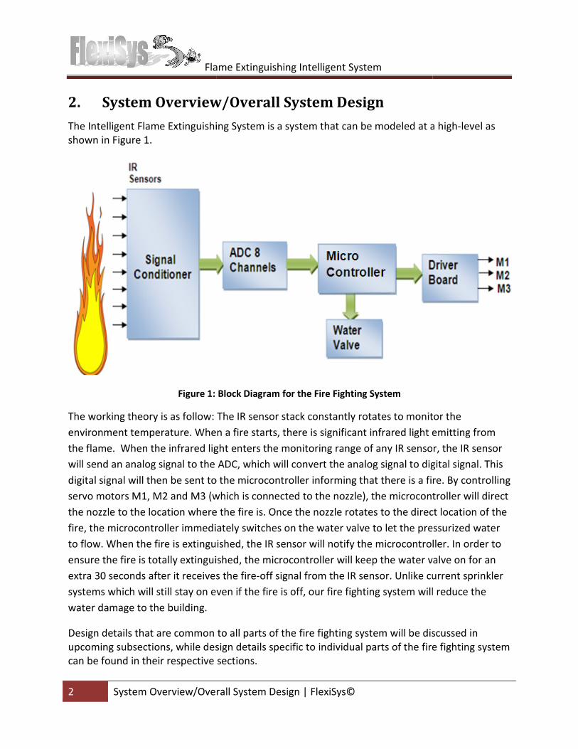
The Intelligent Flame Extinguishing System is a system that can be modeled at a high
shown in Figure 1.
Figure 1:
The working theory is as follow:
environment temperature. When a fire starts, there is significant i
the flame. When the infrared light
will send an analog signal to the ADC, which will convert the analog signal to digital signal
digital signal will then be sent to the microcontroller informing that there is a fire. By controlling
servo motors M1, M2 and M3 (which is
the nozzle to the location where the fire is. Once the nozzle
fire, the microcontroller immediately
to flow. When the fire is extinguished, the IR sensor will notify the microcontroller. In order to
ensure the fire is totally extinguished, the microcontroller will keep the water
extra 30 seconds after it receives the
systems which will still stay on even if the fire is off, our fire fighting system will reduce the
water damage to the building.
Design details that are common to all parts of the
upcoming subsections, while design details specific to individual parts of the
can be found in their respective sections.
Flame Extinguishing Intelligent System
System Overview/Overall System Design | FlexiSys©
System Overview/Overall System Design
The Intelligent Flame Extinguishing System is a system that can be modeled at a high
Block Diagram for the Fire Fighting System
The IR sensor stack constantly rotates to monitor
When a fire starts, there is significant infrared light emitting
light enters the monitoring range of any IR sensor
will send an analog signal to the ADC, which will convert the analog signal to digital signal
be sent to the microcontroller informing that there is a fire. By controlling
(which is connected to the nozzle), the microcontroller will direct
the nozzle to the location where the fire is. Once the nozzle rotates to the direct
immediately switches on the water valve to let the pressurized
en the fire is extinguished, the IR sensor will notify the microcontroller. In order to
ensure the fire is totally extinguished, the microcontroller will keep the water valve
seconds after it receives the fire-off signal from the IR sensor. Unlike current sprinkler
even if the fire is off, our fire fighting system will reduce the
Design details that are common to all parts of the fire fighting system will be discussed in
ming subsections, while design details specific to individual parts of the fire fighting system
can be found in their respective sections.
The Intelligent Flame Extinguishing System is a system that can be modeled at a high-level as
rotates to monitor the
light emitting from
monitoring range of any IR sensor, the IR sensor
will send an analog signal to the ADC, which will convert the analog signal to digital signal. This
be sent to the microcontroller informing that there is a fire. By controlling
, the microcontroller will direct
direct location of the
the pressurized water
en the fire is extinguished, the IR sensor will notify the microcontroller. In order to
valve on for an
. Unlike current sprinkler
even if the fire is off, our fire fighting system will reduce the
will be discussed in
fire fighting system
Flame Extinguishing Intelligent System
3 System Overview/Overall System Design
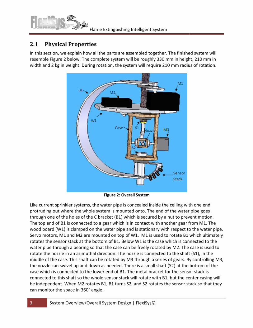
2.1 Physical Properties
In this section, we explain how all the parts are assembled together.
resemble Figure 2 below. The complete system will be roughly 330 mm in height, 210 mm in
width and 2 kg in weight. During rotation,
Like current sprinkler systems, the water pipe is
protruding out where the whole system is mounted onto. The end of the water pipe goes
through one of the holes of the C
The top end of B1 is connected to a gear which is
wood board (W1) is clamped on the water pipe and
Servo motors, M1 and M2 are mounted on top of
rotates the sensor stack at the bottom of B1.
water pipe through a bearing so that the case can be free
rotate the nozzle in an azimuthal direction.
middle of the case. This shaft can be rotated by
the nozzle can swivel up and down as
case which is connected to the lower end of B1.
connected to this shaft so the whole sensor stack will rotate with B1
be independent. When M2 rotates B1, B1 turns
can monitor the space in 360° angle.
Flame Extinguishing Intelligent System
System Overview/Overall System Design | FlexiSys©
Physical Properties
In this section, we explain how all the parts are assembled together. The finished system
Figure 2 below. The complete system will be roughly 330 mm in height, 210 mm in
width and 2 kg in weight. During rotation, the system will require 210 mm radius of rotation
Figure 2: Overall System
he water pipe is concealed inside the ceiling with one end
out where the whole system is mounted onto. The end of the water pipe goes
C bracket (B1) which is secured by a nut to prevent motion.
end of B1 is connected to a gear which is in contact with another gear from
(W1) is clamped on the water pipe and is stationary with respect to the water pipe.
are mounted on top of W1. M1 is used to rotate B1
rotates the sensor stack at the bottom of B1. Below W1 is the case which is connected to the
water pipe through a bearing so that the case can be freely rotated by M2. The case is used to
azimuthal direction. The nozzle is connected to the shaft (S1)
shaft can be rotated by M3 through a series of gears. By controlling
up and down as needed. There is a small shaft (S2) at the bottom of the
ed to the lower end of B1. The metal bracket for the sensor stack is
so the whole sensor stack will rotate with B1, but the center casing will
. When M2 rotates B1, B1 turns S2, and S2 rotates the sensor stack so that
angle.
The finished system will
Figure 2 below. The complete system will be roughly 330 mm in height, 210 mm in
system will require 210 mm radius of rotation.
inside the ceiling with one end
out where the whole system is mounted onto. The end of the water pipe goes
(B1) which is secured by a nut to prevent motion.
gear from M1. The
is stationary with respect to the water pipe.
which ultimately
which is connected to the
The case is used to
shaft (S1), in the
. By controlling M3,
at the bottom of the
sensor stack is
, but the center casing will
rotates the sensor stack so that they
Flame Extinguishing Intelligent System
4 System Overview/Overall System Design
2.2 Power Supply
The following power requirements
• Voltage: 6VDC and 12VDC
• Maximum Current: 3A
• Number of connectors: minimum 4
• Can be run from an electrical
• AC to DC conversion
• Regulated
The maximum current is determined by summing the current requirements for all
components. The solenoid valve
The four connections to the power su
servo motors, and one for the DC
We are going to borrow a power supply from school to pro
system as this will limit the cost of the prototype.
will be connected to a backup power supply to ensure
when the main building power is lost.
2.3 Sensor placement
The MLX90614 infrared thermometer module
vision, which has been chosen as
their accuracy, range and easy interfac
assembled together in a stack of sensors,
combination will allow the system to
preliminary research, flames and fires are most p
addition, our mechanical system currently can only support these 4 sensors, as we are trying to
minimize the amount of space needed for our product.
have a diameter of 9mm to accommodate the size of the barrel of the
Flame Extinguishing Intelligent System
System Overview/Overall System Design | FlexiSys©
The following power requirements for the flame extinguishing intelligent system
6VDC and 12VDC
Number of connectors: minimum 4
electrical outlet
The maximum current is determined by summing the current requirements for all
solenoid valve requires supply voltages of 12V, while the motors require 6
The four connections to the power supply include: one for the solenoid valve, two for the two
DC motor.
We are going to borrow a power supply from school to prove the concept of our fire fighting
limit the cost of the prototype. In the final product, the fire fighting system
up power supply to ensure that the system is always on and active
the main building power is lost.
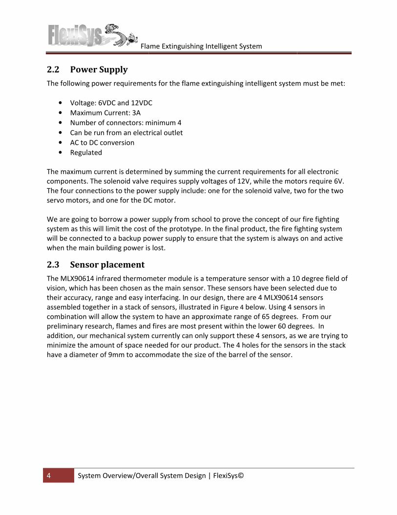
The MLX90614 infrared thermometer module is a temperature sensor with a 10 degree field of
has been chosen as the main sensor. These sensors have been selected due to
their accuracy, range and easy interfacing. In our design, there are 4 MLX90614 sensors
assembled together in a stack of sensors, illustrated in Figure 4 below. Using 4 sensors
allow the system to have an approximate range of 65 degrees.
preliminary research, flames and fires are most present within the lower 60 degrees. In
addition, our mechanical system currently can only support these 4 sensors, as we are trying to
minimize the amount of space needed for our product. The 4 holes for the sensors in the stack
accommodate the size of the barrel of the sensor.
flame extinguishing intelligent system must be met:
The maximum current is determined by summing the current requirements for all electronic
motors require 6V.
two for the two
the concept of our fire fighting
fire fighting system
always on and active
0 degree field of
These sensors have been selected due to
In our design, there are 4 MLX90614 sensors
Using 4 sensors in
s. From our
resent within the lower 60 degrees. In
addition, our mechanical system currently can only support these 4 sensors, as we are trying to
The 4 holes for the sensors in the stack
Flame Extinguishing Intelligent System
5 Physical and Mechanical Design
Figure 3: Sensor MLX90614 Infrared thermometer
module
Figure 5: Dimensions for the sensor stack
3. Physical and Mechanical Design
For our entire physical system, Figure
designing the system, we took into consideration
construction of the system, plexiglass was a consideration,
difficulties in joining plexiglass, wood was a better choice. The ease of obtaining wood and
joining pieces together was definitely a motivation for choosing wood as our base material.
We initially considered using bearings to provide near
out that the bore diameters of the bearings are made only in standard sizes.
pipe is not provided in standard size
washers as bearings instead for our working model. The production
manufacturing, so standard sizes would not be an issue.
Flame Extinguishing Intelligent System
Physical and Mechanical Design | FlexiSys©
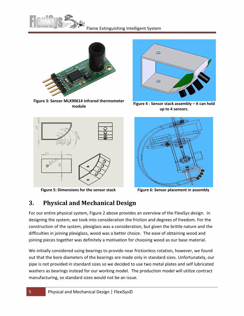
: Sensor MLX90614 Infrared thermometer
Figure 4 : Sensor stack assembly
up to 4 sensors.
: Dimensions for the sensor stack Figure 6: Sensor placement in assembly
Physical and Mechanical Design
Figure 2 above provides an overview of the FlexiSys design. In
designing the system, we took into consideration the friction and degrees of freedom. For the
plexiglass was a consideration, but given the brittle nature and the
glass, wood was a better choice. The ease of obtaining wood and
joining pieces together was definitely a motivation for choosing wood as our base material.
using bearings to provide near frictionless rotation, however,
that the bore diameters of the bearings are made only in standard sizes. Unfortunately,
standard sizes so we decided to use two metal plates and
washers as bearings instead for our working model. The production model will utilize contract
manufacturing, so standard sizes would not be an issue.
: Sensor stack assembly – it can hold
up to 4 sensors.
: Sensor placement in assembly
verview of the FlexiSys design. In
friction and degrees of freedom. For the
but given the brittle nature and the
glass, wood was a better choice. The ease of obtaining wood and
joining pieces together was definitely a motivation for choosing wood as our base material.
, however, we found
Unfortunately, our
ed to use two metal plates and self lubricated
model will utilize contract
Flame Extinguishing Intelligent System
6 Physical and Mechanical Design
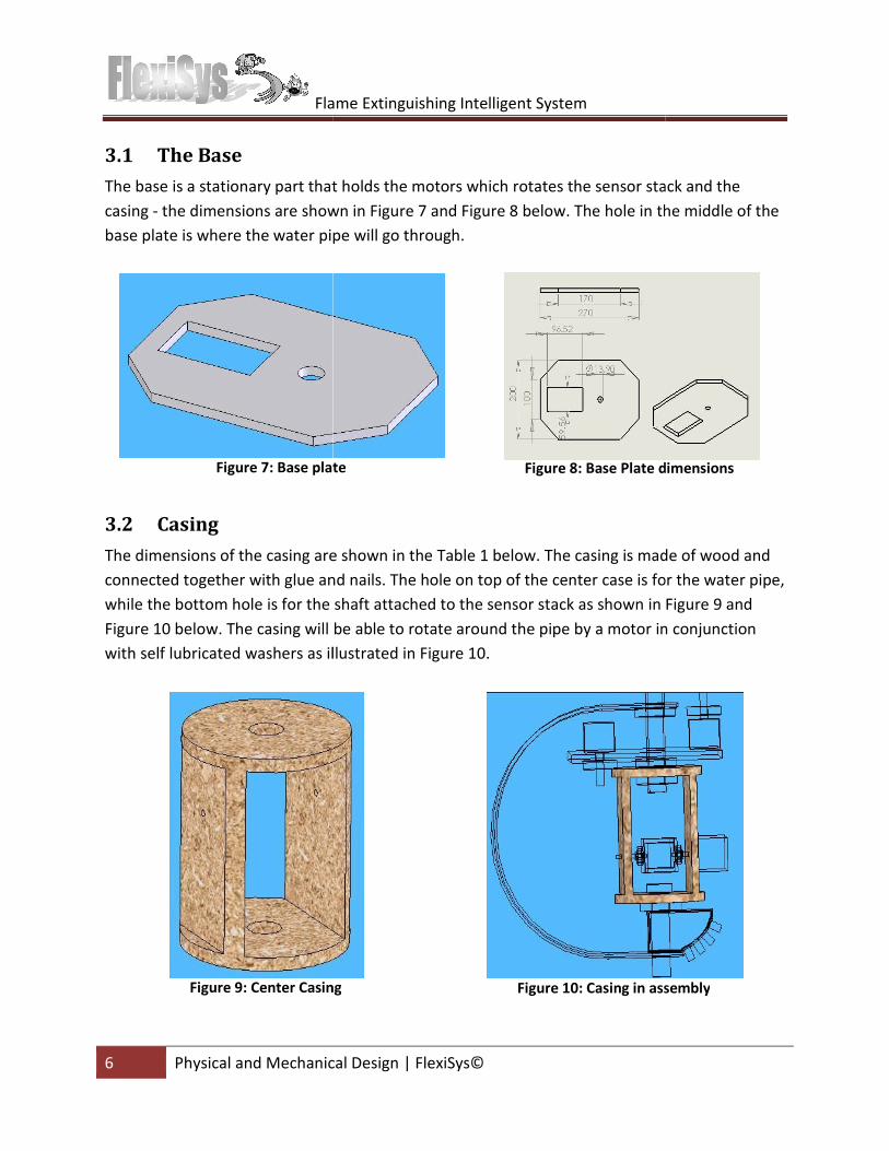
3.1 The Base
The base is a stationary part that holds the motors which
casing - the dimensions are shown in
base plate is where the water pipe will go through.
Figure 7: Base plate
3.2 Casing
The dimensions of the casing are shown in the
connected together with glue and nails. The
while the bottom hole is for the shaft attached to the
Figure 10 below. The casing will be able to rotate around the pipe
with self lubricated washers as illustrated in
Figure 9: Center Casing
Flame Extinguishing Intelligent System
Physical and Mechanical Design | FlexiSys©
ary part that holds the motors which rotates the sensor stack and the
he dimensions are shown in Figure 7 and Figure 8 below. The hole in the middle of the
base plate is where the water pipe will go through.
: Base plate Figure 8: Base Plate dimensions
The dimensions of the casing are shown in the Table 1 below. The casing is made of wood and
together with glue and nails. The hole on top of the center case is for the water pipe,
the shaft attached to the sensor stack as shown in
. The casing will be able to rotate around the pipe by a motor in conjunction
self lubricated washers as illustrated in Figure 10.
: Center Casing Figure 10: Casing in assembly
the sensor stack and the
. The hole in the middle of the
dimensions
The casing is made of wood and
of the center case is for the water pipe,
Figure 9 and
by a motor in conjunction
in assembly
Flame Extinguishing Intelligent System
7 Physical and Mechanical Design
Radius
Height (from top to bottom plane)
Top bore diameter
Bottom bore diameter
Bore diameter for DC motor
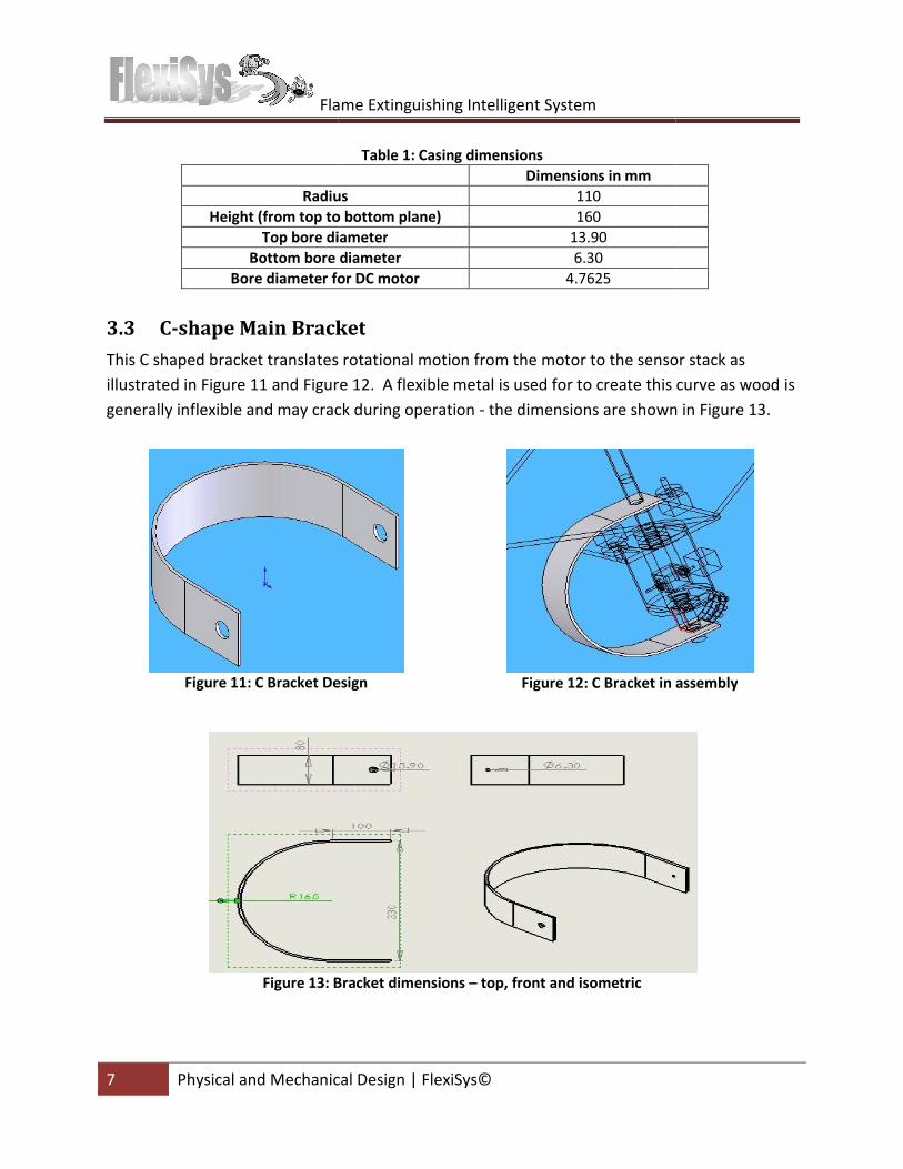
3.3 C-shape Main Bracket
This C shaped bracket translates
illustrated in Figure 11 and Figure
generally inflexible and may crack during operation
Figure 11: C Bracket Design
Figure 13: Bracket dimensions
Flame Extinguishing Intelligent System
Physical and Mechanical Design | FlexiSys©
Table 1: Casing dimensions
Dimensions in mm
Radius 110
Height (from top to bottom plane) 160
Top bore diameter 13.90
Bottom bore diameter 6.30
Bore diameter for DC motor 4.7625
racket
s rotational motion from the motor to the sensor stack as
Figure 12. A flexible metal is used for to create this curve as wood is
and may crack during operation - the dimensions are shown in
: C Bracket Design Figure 12: C Bracket in assembly
: Bracket dimensions – top, front and isometric
motor to the sensor stack as
. A flexible metal is used for to create this curve as wood is
own in Figure 13.
in assembly
Flame Extinguishing Intelligent System
8 Physical and Mechanical Design
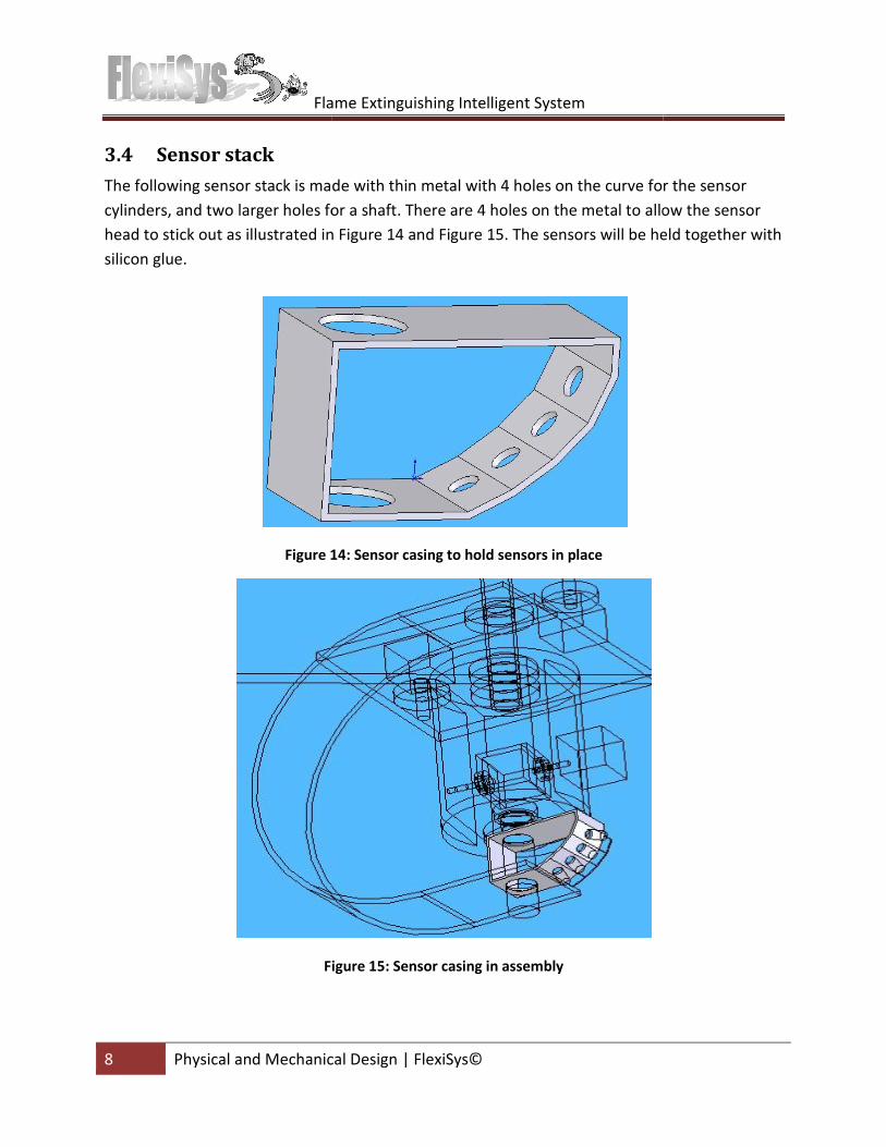
3.4 Sensor stack
The following sensor stack is made
cylinders, and two larger holes for a shaft
head to stick out as illustrated in
silicon glue.
Figure 14
Figure
Flame Extinguishing Intelligent System
Physical and Mechanical Design | FlexiSys©
or stack is made with thin metal with 4 holes on the curve for the sensor
cylinders, and two larger holes for a shaft. There are 4 holes on the metal to allow the sensor
head to stick out as illustrated in Figure 14 and Figure 15. The sensors will be held together with
14: Sensor casing to hold sensors in place
Figure 15: Sensor casing in assembly
with thin metal with 4 holes on the curve for the sensor
There are 4 holes on the metal to allow the sensor
held together with
Flame Extinguishing Intelligent System
9 Physical and Mechanical Design
3.5 Water Pipe
The water pipe we are using is the standard pipe currently used for
water from the city’s water supply
Water Pipeline Design Guidelines
pressure should not exceed 700 kPa (100 psi) to protect the water pipes. Water pipes should be
designed to withstand the transient pressures
shown in Figure 2, the weight of
supported by the water pipe. As mentioned in overall physical properties, t
of these parts are estimated to be around 2 Kg, so the water pipe has
support the whole system while it is rotating. After consulting with a technical specialist
Home Depot, we decide to use a 6.4 mm steel water pipe for the system.
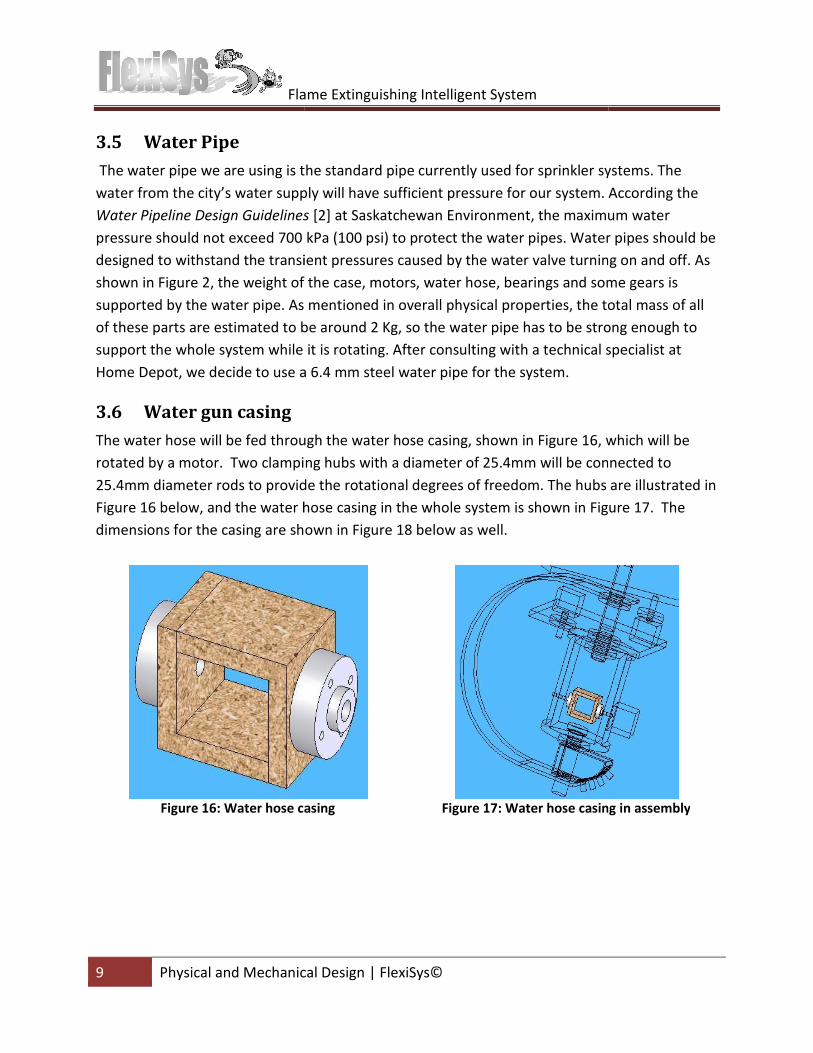
3.6 Water gun casing
The water hose will be fed through the water hose
rotated by a motor. Two clamping hubs
25.4mm diameter rods to provide the rotation
Figure 16 below, and the water hose casing in the whole system is shown in
dimensions for the casing are shown in
Figure 16: Water hose casing
Flame Extinguishing Intelligent System
Physical and Mechanical Design | FlexiSys©
using is the standard pipe currently used for sprinkler system
water supply will have sufficient pressure for our system. According the
Water Pipeline Design Guidelines [2] at Saskatchewan Environment, the maximum
pressure should not exceed 700 kPa (100 psi) to protect the water pipes. Water pipes should be
designed to withstand the transient pressures caused by the water valve turning on and off. As
, the weight of the case, motors, water hose, bearings and some gears
As mentioned in overall physical properties, the total mass of all
are estimated to be around 2 Kg, so the water pipe has to be strong enough to
support the whole system while it is rotating. After consulting with a technical specialist
Home Depot, we decide to use a 6.4 mm steel water pipe for the system.
he water hose will be fed through the water hose casing, shown in Figure 16, wh
clamping hubs with a diameter of 25.4mm will be connected to
rods to provide the rotational degrees of freedom. The hubs are illustrated in
below, and the water hose casing in the whole system is shown in Figure
shown in Figure 18 below as well.
: Water hose casing Figure 17: Water hose casing in assembly
sprinkler systems. The
for our system. According the
imum water
pressure should not exceed 700 kPa (100 psi) to protect the water pipes. Water pipes should be
the water valve turning on and off. As
, water hose, bearings and some gears is
he total mass of all
o be strong enough to
support the whole system while it is rotating. After consulting with a technical specialist at
, which will be
will be connected to
The hubs are illustrated in
Figure 17. The
: Water hose casing in assembly

Flame Extinguishing Intelligent System
10 Electronic System Design
Figure
4. Electronic System Design
4.1 Microcontroller Design
For the “brain” of the system, we will
an open-source electronic prototyping platform with easy to use software and hardware
combination with an active online community
8kB of SRAM and 4kB of EEPROM.
implement in the system. The hardware board requires
input current of 500mA. Another
This low power consumption property makes this microcontroller ideal for our project.
ATmega1280 board has 54 general digital input/output
send out Pulse Width Modulation (PWM) signals
5VDC and 40mA, and can be configur
the pins will be used in this project, with the usage
Table 2
Devices
Sensor Stack (2 for each sensor)
Solenoid Valve
DC Motors
Servo Motors
Flame Extinguishing Intelligent System
Electronic System Design | FlexiSys©
Figure 18: Water hose casing dimensions
Electronic System Design
Microcontroller Design
r the “brain” of the system, we will use the Arduino ATmega1280 microcontroller.
source electronic prototyping platform with easy to use software and hardware
combination with an active online community. The Arduino Mega has 128kB of flash memory,
OM. The total memory size will be plenty for the logic
tem. The hardware board requires a 7-12VDC supply with a maximum
Another power supply option for this board is through
r consumption property makes this microcontroller ideal for our project.
54 general digital input/output pins, with 14 pins having the ability to
send out Pulse Width Modulation (PWM) signals. Each digital pin operates at a maximum of
and can be configured to be either a digital input or output. Currently, 12 of
used in this project, with the usage listed in Table 2 below:
2: List of digital pins used on ATmega1280
Pins used
(2 for each sensor) 8
1
2
1
microcontroller. Arduino is
source electronic prototyping platform with easy to use software and hardware in
. The Arduino Mega has 128kB of flash memory,
for the logic we plan to
a maximum
power supply option for this board is through the USB port.
r consumption property makes this microcontroller ideal for our project.
with 14 pins having the ability to
Each digital pin operates at a maximum of
ed to be either a digital input or output. Currently, 12 of
Flame Extinguishing Intelligent System
11 Electronic System Design
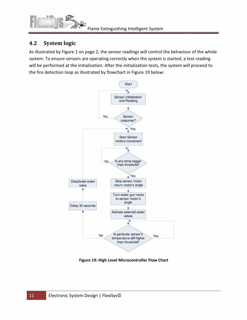
4.2 System logic
As illustrated by Figure 1 on page 2
system. To ensure sensors are operating correctly
will be performed at the initialization. After the initialization tests
the fire detection loop as illustrated by flowchart in
Delay 30 seconds
Deactivate water valve
Figure 19
Flame Extinguishing Intelligent System
c System Design | FlexiSys©
on page 2, the sensor readings will control the behaviour
operating correctly when the system is started, a test reading
ed at the initialization. After the initialization tests, the system will proceed
loop as illustrated by flowchart in Figure 19 below:
Start
Sensor Initialization and Reading
Start Sensor motors movement
Sensor response?
No
Yes
Is any temp bigger than threshold?
No
Yes
Stop sensor motor return motor’s angle
Turn water gun motor to sensor motor’s
angle
Activate solenoid water valves
Is particular sensor’s temperature still higher
than threshold?
YesNo
seconds
Deactivate water
19: High Level Microcontroller Flow Chart
the behaviour of the whole
, a test reading
will proceed to
Flame Extinguishing Intelligent System
12 Electronic System Design
Once the system starts the sensor motor movement,
the temperature every millisecond
temperature exceeds 200⁰C, the
between the sensor stack and the nozzle will be sent to the microcontroller. The w
motor will then rotate with this angle and activate
the system will still constantly check the
100⁰C, the system will continue spraying water
deactivating the water valve. The sensor
Since our system is meant to be automatic,
4.3 Thermal Sensors
Our system uses thermal sensors to
MLX90614 Infrared Thermometer Modules from Parallax. These are non
are able to pick up heat signature
1ms and has a low power consumption
our FlexiSys product.
4.4 Serial data communication with the Arduino
Reading the temperature from the
the serial I/O pins on the sensor. To read
microcontroller needs to send the
receive the reading on the same pin
receive (RX) and transmit (TX) connection
library provided by Arduino developers to configure general digital I/O pins to output serial
commands and receive serial input
temperatures from the MLX90614 modules.
Flame Extinguishing Intelligent System
Electronic System Design | FlexiSys©
system starts the sensor motor movement, the microcontroller will constantly check
millisecond to see if any of the readings exceed 200⁰C. If the
the motor (M1) controlling the sensor stack will stop and the angle
between the sensor stack and the nozzle will be sent to the microcontroller. The w
angle and activate the solenoid water valve. During this time,
constantly check the temperature. Once the temperature drop
tem will continue spraying water for 30 seconds as a precaution before
deactivating the water valve. The sensor stack will continue to rotate after these 30 seconds.
Since our system is meant to be automatic, the system will continue in an infinite loop
thermal sensors to act as the “eyes” of the system. The model we use is 10
0614 Infrared Thermometer Modules from Parallax. These are non-contact sensors that
are able to pick up heat signatures in range of 10 meters. MLX90614 has a fast refresh rate of
consumption of 5 VDC and 20mA which makes this sensor
Serial data communication with the Arduino
the MLX90614 is performed via serial command through one
sensor. To read the current temperature on module’s RAM,
the serial command “!TEMR” to the sensor I/O, which will
same pin from the sensor. On our microcontroller, there is limited
receive (RX) and transmit (TX) connections on board. Hence, we will use the NewSoftSerial
library provided by Arduino developers to configure general digital I/O pins to output serial
serial inputs respectively. Figure 20 displays the flow chart
614 modules.
constantly check
⁰C. If the
motor (M1) controlling the sensor stack will stop and the angle
between the sensor stack and the nozzle will be sent to the microcontroller. The water gun
solenoid water valve. During this time,
temperature drops below
s a precaution before
stack will continue to rotate after these 30 seconds.
system will continue in an infinite loop.
“eyes” of the system. The model we use is 10⁰
contact sensors that
in range of 10 meters. MLX90614 has a fast refresh rate of
this sensor ideal for
MLX90614 is performed via serial command through one of
urrent temperature on module’s RAM, the
which will then
sensor. On our microcontroller, there is limited
NewSoftSerial
library provided by Arduino developers to configure general digital I/O pins to output serial
displays the flow chart to read
Flame Extinguishing Intelligent System
13 Electronic System Design
Figure
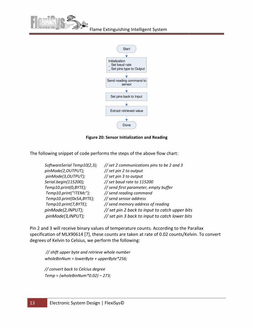
The following snippet of code performs the steps of the above flow chart:
SoftwareSerial Temp10(2,3);
pinMode(2,OUTPUT);
pinMode(3,OUTPUT);
Serial.begin(115200);
Temp10.print(0,BYTE);
Temp10.print("!TEMc");
Temp10.print(0x5A,BYTE);
Temp10.print(7,BYTE);
pinMode(2,INPUT);
pinMode(3,INPUT);
Pin 2 and 3 will receive binary values of temperature
specification of MLX90614 [7], these counts are taken at rate
degrees of Kelvin to Celsius, we perform the following:
// shift upper byte and retrieve whole number
wholeBinNum = lowerByte + upperByte*256;
// convert back to Celcius degree
Temp = (wholeBinNum*0.02)
Flame Extinguishing Intelligent System
Electronic System Design | FlexiSys©
Initialization_ Set baud rate_ Set pins type to Output
Send reading command to sensor
Set pins back to Input
Extract retrieved value
Start
Done
Figure 20: Sensor Initialization and Reading
The following snippet of code performs the steps of the above flow chart:
SoftwareSerial Temp10(2,3); // set 2 communications pins to be 2 and 3
// set pin 2 to output
// set pin 3 to output
// set baud rate to 115200
// send first parameter, empty buffer
// send reading command
// send sensor address
// send memory address of reading
// set pin 2 back to input to catch upper bits
// set pin 3 back to input to catch lower bits
ry values of temperature counts. According to the Parallax
, these counts are taken at rate of 0.02 counts/Kelvin
us, we perform the following:
shift upper byte and retrieve whole number
wholeBinNum = lowerByte + upperByte*256;
// convert back to Celcius degree
Temp = (wholeBinNum*0.02) – 273;
// set pin 2 back to input to catch upper bits
// set pin 3 back to input to catch lower bits
Parallax
of 0.02 counts/Kelvin. To convert
Flame Extinguishing Intelligent System
14 Electronic System Design
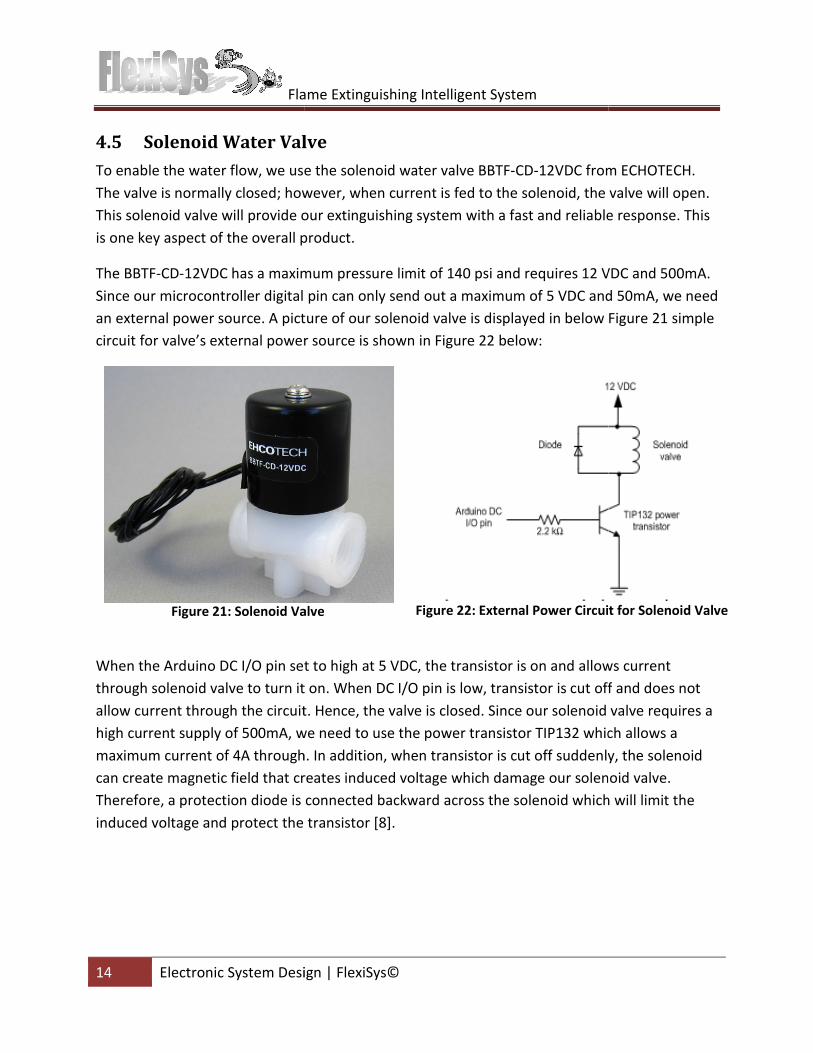
4.5 Solenoid Water Valve
To enable the water flow, we use
The valve is normally closed; however, when
This solenoid valve will provide our extinguishing system
is one key aspect of the overall product.
The BBTF-CD-12VDC has a maximum pressure limit of 140 psi
Since our microcontroller digital pin can only send out
an external power source. A picture of our solenoid valve is displayed in
circuit for valve’s external power source is shown in
Figure 21: Solenoid Valve
When the Arduino DC I/O pin set to high at 5 VDC,
through solenoid valve to turn it on. When DC I/O pin is low, transistor is cut off
allow current through the circuit. Hence,
high current supply of 500mA, we need to use
maximum current of 4A through.
can create magnetic field that creates
Therefore, a protection diode is connected backward
induced voltage and protect the transistor
Flame Extinguishing Intelligent System
Electronic System Design | FlexiSys©
Solenoid Water Valve
, we use the solenoid water valve BBTF-CD-12VDC from
d; however, when current is fed to the solenoid, the
our extinguishing system with a fast and reliable response. This
is one key aspect of the overall product.
maximum pressure limit of 140 psi and requires 12 VDC and 500mA
Since our microcontroller digital pin can only send out a maximum of 5 VDC and 50mA, we need
picture of our solenoid valve is displayed in below Figure
circuit for valve’s external power source is shown in Figure 22 below:
: Solenoid Valve Figure 22: External Power Circuit for Solenoid Valve
Arduino DC I/O pin set to high at 5 VDC, the transistor is on and allow
turn it on. When DC I/O pin is low, transistor is cut off
current through the circuit. Hence, the valve is closed. Since our solenoid valve requires a
high current supply of 500mA, we need to use the power transistor TIP132 which
maximum current of 4A through. In addition, when transistor is cut off suddenly,
creates induced voltage which damage our solenoid valve.
Therefore, a protection diode is connected backward across the solenoid which will limit
and protect the transistor [8].
12VDC from ECHOTECH.
valve will open.
reliable response. This
and requires 12 VDC and 500mA.
5 VDC and 50mA, we need
Figure 21 simple
: External Power Circuit for Solenoid Valve
transistor is on and allows current
turn it on. When DC I/O pin is low, transistor is cut off and does not
valve is closed. Since our solenoid valve requires a
which allows a
denly, the solenoid
damage our solenoid valve.
across the solenoid which will limit the
Flame Extinguishing Intelligent System
15 Electronic System Design
4.6 Motor design
4.6.1 Servo Motors
For the water gun movements and sensor movements, we decided to use servo motors
SPG425A. The servo motor controlling the
our system to precisely locate
same angle. SPG425A is a multi
motor is able to create 5.43 N
maximum operating voltage for these motors is 6V.
To control the servo motor through
provided by Arduino developer, and to rotate
Arduino command will be used:
myservo.write(pos); // rotate myservo to angle pos
where: myservo: object of servo class
pos: Angle of rotation
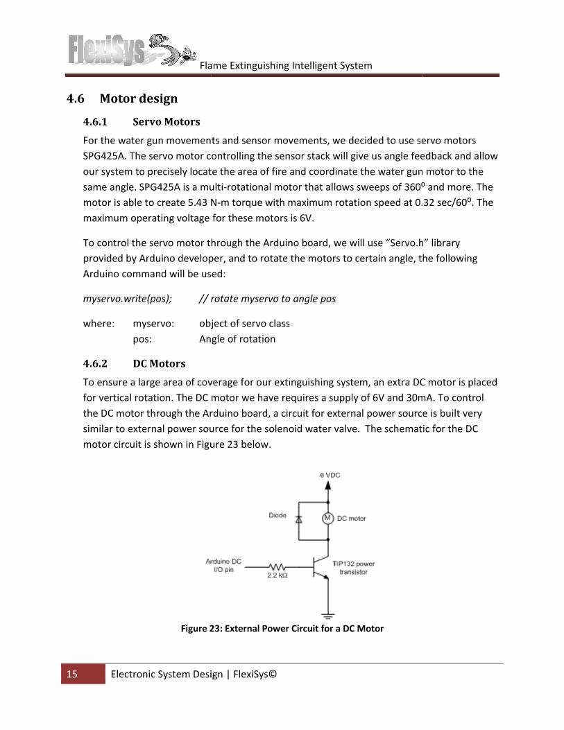
4.6.2 DC Motors
To ensure a large area of coverage for our extinguishing system, an extra DC motor is placed
for vertical rotation. The DC motor we have require
the DC motor through the Arduino board, a circuit for external power source is built very
similar to external power source
motor circuit is shown in Figure
Figure 23
Flame Extinguishing Intelligent System
Electronic System Design | FlexiSys©
water gun movements and sensor movements, we decided to use servo motors
controlling the sensor stack will give us angle feedback
our system to precisely locate the area of fire and coordinate the water gun motor to the
same angle. SPG425A is a multi-rotational motor that allows sweeps of 360⁰ and more. The
motor is able to create 5.43 N-m torque with maximum rotation speed at 0.32 sec/60
aximum operating voltage for these motors is 6V.
servo motor through the Arduino board, we will use “Servo.h” library
Arduino developer, and to rotate the motors to certain angle, the following
Arduino command will be used:
// rotate myservo to angle pos
object of servo class
Angle of rotation
of coverage for our extinguishing system, an extra DC motor is placed
The DC motor we have requires a supply of 6V and 30mA. To control
Arduino board, a circuit for external power source is built very
to external power source for the solenoid water valve. The schematic for
Figure 23 below.
23: External Power Circuit for a DC Motor
water gun movements and sensor movements, we decided to use servo motors
will give us angle feedback and allow
water gun motor to the
⁰ and more. The
otation speed at 0.32 sec/60⁰. The
Arduino board, we will use “Servo.h” library
to certain angle, the following
of coverage for our extinguishing system, an extra DC motor is placed
supply of 6V and 30mA. To control
Arduino board, a circuit for external power source is built very
chematic for the DC
Flame Extinguishing Intelligent System
16 System Test Plan | FlexiSys
5. System Test Plan
5.1 Unit Testing
5.1.1 Sensor
• Turn one sensor on at a time
the temperature.
• Turn on all sensors and
• Create different temperature
locate the fire.
• Verify that the sensor
least 3 hours).
5.1.2 Solenoid Valve
• Verify that valve will not leak water
• Verify that water will flow through when the valve is turned on.
• Verify that the valve will open within 0.5 second
5.1.3 Motors
• Verify that the motors
• Verify that the motors have e
• Verify that the motors do not draw more current than intended
5.2 No Fire Scenario
Conditions: No fire appears within the monitored space.
Expected Observations: The sensor stack
The sensor stack completes each 360
and the nozzle should be
5.3 Fire scenario
Conditions: Fire of at least 20cm
of the system.
Expected Observations: System stops rotating with sensor pointing
the fire. Water gun then
water. Once the flame is extinguished,
and then deactivates. The s
Flame Extinguishing Intelligent System
FlexiSys©
lan
Turn one sensor on at a time to ensure each sensor will be able to accurately
s and ensure all sensors are able to detect accurate temperatur
Create different temperatures at each sensor and ensure the sensor stack is
sensors are stable for long time and able to maintain accuracy (
Verify that valve will not leak water when closed.
that water will flow through when the valve is turned on.
valve will open within 0.5 seconds after sending signal
motors are able to rotate to the intended angle when
motors have enough torque to carry water gun and sensor stack
motors do not draw more current than intended.
No fire appears within the monitored space.
The sensor stack must rotate 360° back and forth constantly
The sensor stack completes each 360° rotation in 5 seconds. During this time, t
should be stationary.
: Fire of at least 20cm in height and width appear randomly within 3 meter
System stops rotating with sensor pointing in the direction of
rotates to the same direction as the sensor and start
flame is extinguished, the water gun continues shooting for
The system then resumes to normal sensor sweeping.
accurately detect
able to detect accurate temperatures.
and ensure the sensor stack is able to
able to maintain accuracy (at
after sending signal.
intended angle when a signal sent.
sensor stack.
back and forth constantly.
During this time, the case
height and width appear randomly within 3 meters
in the direction of
sensor and starts shooting
ooting for 30 seconds
to normal sensor sweeping.

Flame Extinguishing Intelligent System
17 Conclusion | FlexiSys©
6. Conclusion
These proposed design specifications provide details that will fully satisfy the functional
requirements of the working model of the Flame Extinguishi
development of the model progresses, these design specifications will be the foundation for
each component and integration. Further optimizations will be discussed and revisions will be
completed when members unanimously agr
ensure the safety and robustness of our system.
system is on track to be completed by April 15, 2010.
Flame Extinguishing Intelligent System
©
These proposed design specifications provide details that will fully satisfy the functional
requirements of the working model of the Flame Extinguishing Intelligent System. As the
development of the model progresses, these design specifications will be the foundation for
each component and integration. Further optimizations will be discussed and revisions will be
completed when members unanimously agree. In addition, test plans have been included to
ensure the safety and robustness of our system. Development has been progressin
system is on track to be completed by April 15, 2010.
These proposed design specifications provide details that will fully satisfy the functional
ng Intelligent System. As the
development of the model progresses, these design specifications will be the foundation for
each component and integration. Further optimizations will be discussed and revisions will be
In addition, test plans have been included to
been progressing and our
Flame Extinguishing Intelligent System
18 References | FlexiSys©
References
[1] FlexiSys, “Functional Specifications for a Flame E
Simon Fraser University, Burnaby, BC, Canada, February 2010.
[2] Saskatchewan Environment,
Available:
http://www.saskh2o.ca/DWBinder/EPB276WaterPipelineDesignGuidelines.pdf
[Accessed: March 04,2010]
[3] Servocity.com, Set Screw Hubs
http://www.servocity.com/html/set_screw_hubs.html. [Accessed: March 08, 2010]
[4] Servocity.com, 48 Pitch Aluminum Hub Gears (.250" Face),
http://www.servocity.com/html/48_pitch_aluminum_hub_gears___.html. [Accessed:
March 08, 2010]
[5] Servocity.com, SPG425A
http://www.servocity.com/html/spg425a
08, 2010]
[6] Servocity.com, SPG425A
http://www.servocity.com/html/spg425a
March 08, 2010]
[7] Parallax.com, MLX90614 Infrared Thermometer Modules
http://www.parallax.com/Portals/0/Downloads/docs/prod/sens/28040
IRThermometer-v2.0.pdf. [Accessed: March 09, 2010]
[8] Kpsec.freeuk.com, Transistor Circuits
http://www.kpsec.freeuk.com/trancirc.h
[9] Arduino.cc, Arduino Mega
http://arduino.cc/en/Main/ArduinoBoardMega?action=diff
2010]
[10] Arduiniana.org, NewSoftSerial
http://arduiniana.org/librari
[11] Arduino.cc, Sweep, 2009. [Online]. Available:
[Accessed: March 01, 2010]
[12] Letsmakerobots.com, DC motor control with Arduino
http://letsmakerobots.com/node/7990
Flame Extinguishing Intelligent System
©
FlexiSys, “Functional Specifications for a Flame Extinguishing Intelligent System”,
Simon Fraser University, Burnaby, BC, Canada, February 2010.
Saskatchewan Environment, Water Pipeline Design Guidelines, 2004. [Online].
http://www.saskh2o.ca/DWBinder/EPB276WaterPipelineDesignGuidelines.pdf
[Accessed: March 04,2010]
Set Screw Hubs, 2008. [Online]. Available:
http://www.servocity.com/html/set_screw_hubs.html. [Accessed: March 08, 2010]
48 Pitch Aluminum Hub Gears (.250" Face), 2008. [Online]. Available:
/www.servocity.com/html/48_pitch_aluminum_hub_gears___.html. [Accessed:
SPG425A-360 360o Rotation, 2008. [Online]. Available:
http://www.servocity.com/html/spg425a-360_360o_rotation.html. [Accessed: March
SPG425A-BM-360 360o Rotation, 2008. [Online]. Available:
http://www.servocity.com/html/spg425a-bm-360_360o_rotation.html. [Accessed:
MLX90614 Infrared Thermometer Modules, 2008. [Online]. Available:
http://www.parallax.com/Portals/0/Downloads/docs/prod/sens/28040
v2.0.pdf. [Accessed: March 09, 2010]
Transistor Circuits, 2010. [Online]. Available:
http://www.kpsec.freeuk.com/trancirc.htm. [Accessed: March 09, 2010]
Arduino Mega, 2009. [Online]. Available:
http://arduino.cc/en/Main/ArduinoBoardMega?action=diff. [Accessed: March 08,
NewSoftSerial, 2010. [Online]. Available:
http://arduiniana.org/libraries/NewSoftSerial/. [Accessed: March 05, 2010]
, 2009. [Online]. Available: http://arduino.cc/en/Tutorial/Sweep
[Accessed: March 01, 2010]
DC motor control with Arduino, 2009. [Online]. Avaliable:
bots.com/node/7990. [Accessed: March 10, 2010]
xtinguishing Intelligent System”,
2004. [Online].
http://www.saskh2o.ca/DWBinder/EPB276WaterPipelineDesignGuidelines.pdf.
http://www.servocity.com/html/set_screw_hubs.html. [Accessed: March 08, 2010]
2008. [Online]. Available:
/www.servocity.com/html/48_pitch_aluminum_hub_gears___.html. [Accessed:
360_360o_rotation.html. [Accessed: March
, 2008. [Online]. Available:
360_360o_rotation.html. [Accessed:
, 2008. [Online]. Available:
http://www.parallax.com/Portals/0/Downloads/docs/prod/sens/28040-28042-
. [Accessed: March 09, 2010]
. [Accessed: March 08,
. [Accessed: March 05, 2010]
http://arduino.cc/en/Tutorial/Sweep.
, 2009. [Online]. Avaliable:


![Autonomous Vehicle Ultrasonic Sensor Vulnerability and Impact … · 2018-02-13 · Ultrasonic sensor (also known as sonar) is a sensor that uses echolocation (see Figure 1) [3] to](https://img.pdfslide.net/doc/110x75/5e7a6ad3d4a07a01c71e3c47/autonomous-vehicle-ultrasonic-sensor-vulnerability-and-impact-2018-02-13-ultrasonic.jpg)