Embed Size (px)
Citation preview

i
SchoolofScienceandEngineering
DAMAGEANALYSISOFCSPPARABOLICTROUGHHEATCOLLECTORELEMENTFOREFFICIENCYIMPROVEMENT
Capstone Design
Spring2017by
IkhlasGhiat
Supervisedby
Dr.AsmaeKhaldoune
ii
DAMAGEANALYSISOFCSPPARABOLICTROUGHHEATCOLLECTORELEMENTFOREFFICIENCYIMPROVEMENT
Capstone Final Report
_____________________________________________________
Ikhlas Ghiat
Approved by the supervisor
_____________________________________________________
Dr. Asmae Khaldoune

iii
Acknowledgements
First of all, I would like to express my deepest gratitude and special thanks to my supervisor, Dr.
Asmae Khaldoune, for her continuous availability, guidance, and support. I would also like to thank
her for assigning to me this concrete, and real-life project, by which I had the opportunity to
discover my passion, and what I want to do next.
Secondly, I would like to thank my family, especially my parents, for their incredible support,
encouragement, and continuous love throughout my four years of university. I would like to thank
my father, who has been of great technical and methodological help in this project, and my mother
who has given me faith and confidence to successfully finish this project. Words would not express
my endless gratitude for all the sacrifices they made.
Finally, I would like to thank my friends for their support and care. In addition, I would like to
thank Al Akhawayn University, for this overall great experience.

iv
Table of Contents
Acknowledgements ....................................................................................................................... iii
List of Tables and Figures ............................................................................................................. v Abstract .......................................................................................................................................... vi
1 Introduction ............................................................................................................................ 1 1.1 Concentrated Solar Power ................................................................................................ 1 1.2 Steeple Analysis ............................................................................................................... 3
2 Background ............................................................................................................................ 5 2.1 Parabolic Trough Technology .......................................................................................... 5
2.1.1 Mirrors and Support Structure ..................................................................................... 5 2.1.2 Heat Collector Element (HCE) .................................................................................... 5 2.1.3 Heat Transfer Fluid ...................................................................................................... 6 2.1.4 Thermal Storage ........................................................................................................... 7 2.1.5 Solar Power Cycle ........................................................................................................ 7
2.2 Noor Power Station .......................................................................................................... 8 2.3 Problem Statement ........................................................................................................... 9
3 State of the Art ..................................................................................................................... 10 4 Methodology ......................................................................................................................... 12
5 HCE Damage Analysis ........................................................................................................ 13 5.1 Design Related Possible Causes .................................................................................... 13
5.1.1 Glass-to-metal Seal Breakage .................................................................................... 13 5.1.2 HTF Cracking ............................................................................................................ 14 5.1.3 Aluminum Shield Diffusivity .................................................................................... 16
5.2 Operational Possible Causes .......................................................................................... 17 5.2.1 HTF Mass Flow Rate in Winter ................................................................................. 17
5.3 Software Analysis of Vacuum Loss ............................................................................... 18 5.3.1 Problem specifications ............................................................................................... 18 5.3.2 Pre-Analysis and Start-up .......................................................................................... 19 5.3.3 Geometry .................................................................................................................... 20 5.3.4 Mesh ........................................................................................................................... 21 5.3.5 Physics Setup ............................................................................................................. 22 5.3.6 Numerical Solution .................................................................................................... 24 5.3.7 Numerical Results ...................................................................................................... 25
6 Solution Design ..................................................................................................................... 27 6.1 Dynamic Vacuum .......................................................................................................... 27
7 Limitations and Future Work ............................................................................................ 27
8 Conclusion ............................................................................................................................ 29 References ..................................................................................................................................... 30

v
List of Tables and Figures Figure 1: Linear Fresnel Collector.... .............................................................................................. 2
Figure 2: Parabolic Trough Collector ............................................................................................. 2
Figure 3: Dish Stiriling ..... ............................................................................................................. 2
Figure 4: Solar Power Tower .......................................................................................................... 2
Figure 5: Heat Collector Element ................................................................................................... 6
Figure 6: Power Cycle .................................................................................................................... 8
Figure 7: Glass Envelope Breakage ................................................................................................ 9
Figure 8: Glass-to-metal Seal ....................................................................................................... 14
Figure 9: Project Schematics ........................................................................................................ 19
Figure 10: CFD Pre-Analysis ....................................................................................................... 19
Figure 11: Heat Transfer Pre-Analysis ......................................................................................... 20
Figure 12: Mesh Model ................................................................................................................. 21
Figure 13: Details of Mesh ........................................................................................................... 21
Figure 14: Solar Calculator ........................................................................................................... 22
Figure 15: Conjugate Heat Transfer-CFD Results ....................................................................... 25
Figure 16: Static Structural Results .............................................................................................. 26
Figure 17: Computer Limitations ................................................................................................. 27
Table 1: Geometry Properties ....................................................................................................... 20
Table 2: Material Properties .......................................................................................................... 23
Table 3: Boundary Condition Entries ........................................................................................... 23

vi
Abstract
Heat collector elements are a key component of CSP parabolic troughs. They play a vital role in
the optimal operation of any solar power plant. In fact, any problem related to these absorbers
decreases the efficiency and performance of the entire production plant. Starting early winter, a
high number of HCEs were damaged in Noor 1 plant.
The objective of this capstone project is to conduct an analysis of CSP parabolic trough HCEs in
order to investigate their damage, and find a solution to that. In fact, the damage of heat collector
elements may be due to several causes, either design related or operational mistakes. Most of these
problems lead to a more concrete and narrowed problem, which is the loss of vacuum in the annulus
zone.
This project involves four principal milestones. The first milestone consists of analyzing all
possible design related causes leading to HCE damage; mainly glass-to-metal seal breakage, HTF
cracking, and shield diffusivity. The second milestone entangles some of the possible operational
problems, principally observed in Noor power station. The third milestone is devoted to a detailed,
coupled numerical analysis of the effects of vacuum loss using ANSYS software. This later
analysis is conducted in two main steps; first a CFD conjugate heat transfer analysis, followed by
a Static Structural analysis. Finally, the fourth milestone involves a solution design suggestion to
encounter the damage problem.
The analysis conducted in this project proved our theory that when vacuum is lost in the annulus
part, the glass casing of HCE breaks. Thus, the solution suggested in this project is the
implementation of a dynamic vacuum design.
Keywords: CSP parabolic trough, Heat collector element, Glass-to-metal seal, HTF, CFD
analysis, Static Structural analysis, dynamic vacuum.

1
1 Introduction
Nowadays the rapid development of renewable energy technologies is positively impacting our
environment and society. In fact, most renewable energy sources produce little or no carbon dioxide
emissions which reduces global warming. They also reduce air pollution and consequently improve
public health. Additionally, they contribute to the social and economic development by offering
more job opportunities especially for the rural population. Also, they provide a diverse, and more
politically stable energy supply.
Although renewable energies have some negative aspects such as noise, land-use, and a negative
impact on wildlife, but these drawbacks are trivial and can be reduced in future work.
1.1 Concentrated Solar Power
Solar radiation received in Earth can be converted to electrical power either directly using
photovoltaic devices or indirectly using concentrated solar power. Photovoltaic devices convert
light into electric current using the photovoltaic effect. For the concentrated solar systems, they
generate power by concentrating a large area of sunlight onto a small part. The concentrated light
is then converted to heat which drives a heat engine which in turn drives an electrical power
generator. Contrary to photovoltaic devices, concentrated solar technologies have the ability to
store energy and use it at moments with no or low sunlight.
There are four type of concentrated solar technologies, mainly divided into two categories: line
concentrating and point concentrating collectors. The important line concentrating technologies are
parabolic troughs (Fig2), and Fresnel reflectors (Fig1). These later technologies have the ability to
concentrate solar radiation into an absorber tube where a working fluid is heated up to 400°C.
Linear Fresnel collectors are considered a variation of parabolic troughs. However, the main
difference between these two collectors is that linear Fresnel collectors are composed of linear
mirrors instead of parabolic ones. Fresnel collectors also have a less concentration and optical
efficiency than parabolic troughs, which makes them less standardized.

2
Figure1:LinearFresnelCollector Figure2:ParabolicTroughCollector
Concerning point concentrated systems, the two main technologies are dish Stirling (Fig3) system
and solar power tower (Fig4). The dish Stirling technology consists of a parabolic dish that
concentrates light onto a receiver located at the focal point of the reflector. For the solar power
tower, this technology involves dual-axis tracking reflectors called heliostats, which concentrate
light onto a single receiver located at the top of a tower. A fluid in the receiver absorbs thermal
energy for power generation and storage through a thermodynamic cycle. One of the advantages
of the solar tower technology is that only the reflectors needs adjustment, whereas the tower stays
stable. In fact, solar tower technologies operate at higher temperatures than parabolic troughs and
Fresnel technologies because of the point concentration to a single receiver [1].
Figure3:DishStiriling Figure4:SolarPowerTower
3
The focus of this paper will be on the line concentrator parabolic trough technologies. The project
consists of conducting an analysis of the damages at the level of heat collector elements of parabolic
troughs. The first part will consist of introducing the different elements of parabolic troughs as well
as their operating mechanism. Followed by a literature review that helped to shape this project, and
show its use and added value. Then the damage analysis chapter which is divided into two main
sections; first the theoretical analysis part, and second a numerical analysis part using a simulation
software. The final section consists of a solution design suggested to encounter the damage
problem.
1.2 Steeple Analysis
This project is directly investigating the causes behind the damaged heat collector tubes/elements
(HCEs) in Noor 1 plant. Clearly defining the problem will lead us to find a solution for the cracking
of the HCEs which will improve the efficiency of the CSP plant. This is a concrete and real-life
project, which means it has several implications on the country.
Social: The implementation of this project will certainly need a lot of investment, so it is necessary
to investigate the societal aspect towards this project. Interests towards green energy are increasing,
however it is important to mention that many Moroccan citizens lack informational sources about
the weight of these technologies. So, it is crucial to work on raising awareness about environmental
protection methods and alternatives.
Technological: This project mainly comports an analysis part of the already existing HCEs and a
design part which will present a solution to this problem. These two parts will be tackled using
ANSYS software. As for the implementation part, which will follow the work of this project, the
maintenance company needs to make sure that Morocco has the qualified industrial companies to
produce the new design. Otherwise they need to outsource the production of the new HCEs.
Economic: Improving the efficiency of the CSPs found in Noor plant will decrease the cost of
electricity bills, and will decrease the dependency of electricity production on fuel. Moreover,
Morocco will loosen its dependency on other countries in importing both electricity and fuel such
as Spain, Algeria, and Middle Eastern countries.

4
Environmental: The Noor project is classified under electricity and renewable energy category by
the Minister of Energy, Mines, Water and Environment. In addition to that, the new suggested
design will follow all environmental aspects, and will support the main objective of Noor project.
However, in the implementation process, following this capstone’s work, the company has to make
sure that the production of the new design is following environmental regulations such as ISO
14000.
Political: This project will improve and increase electricity production of Noor plants, which will
make Morocco less dependent on other countries in terms of energy. It will give Morocco more
autonomy and independency, will promote a good image of the country, and will display its
strength in front of other countries.
Legal: This project will have the possibility to be implemented through n°13-09 law which is part
of the Royal Highlights that give priority to renewable energy and sustainable development. This
law mainly addresses the legal gaps in renewable energy, and promotes investment.
Ethical: The ethical part of this project is that by improving the efficiency of the HCEs, Noor
project will continue to advance and succeed, thus producing more electricity, and offering more
jobs for the rural population. Integrating the rural population in Noor project is one of the intended,
aimed at ethical aspect of the plants.
5
2 Background
2.1 Parabolic Trough Technology
Parabolic trough technology has many uses and applications depending on its operating
temperature. As mentioned earlier, parabolic troughs are based on a line concentrating system,
where a working fluid passes through a heat collector element, absorbs heat, and generates power.
In fact, parabolic troughs are used in concentrated solar power plants for electricity production.
The operating temperature of this latter application ranges from 300°C to 400°C. Whereas for
industrial process heat (IPH) applications, the operating temperatures are 100°C to 250°C.
In this capstone project, we are concerned with the first application only. To produce electricity
through parabolic troughs, there are two possible steam power plant integration approaches. Either
the parabolic troughs are directly related to the steam power plant through a Direct Steam
Generation (DSG) system, or indirectly by heating a working fluid which then exchanges heat in a
heat exchanger for steam generation, and thus power production.
2.1.1 Mirrors and Support Structure
Parabolic through mirror reflectors are made of ultra-clear tempered glass with a reflectivity up to
94.5% depending on the glass thickness and technology. The mirrors are coated with a silver
reflective layer, followed by a copper layer and three other layers that guarantee durability, or
coated by polished aluminum and metallized acrylic. The first coating is the best because it has a
higher solar reflectance.
The support structure for these reflectors is an essential aspect in a good performance of the entire
plant. The structure has to be stiff and should be able to withstand deformations related to the
weight of the reflectors, the wind, and the expansion of HCEs. Also, the structure should have an
easiness to the one-axis tracking system that maximizes the total solar absorbance [2].
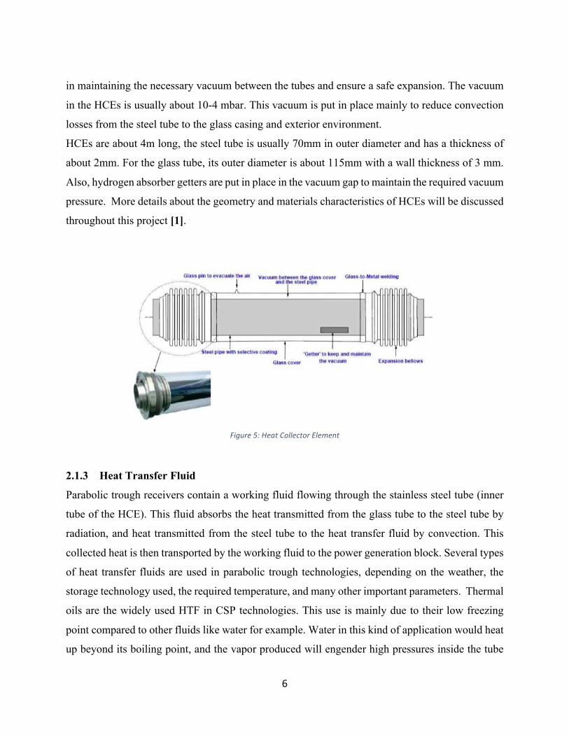
2.1.2 Heat Collector Element (HCE)
Heat collector elements or receiver tube is one of the most important components of a parabolic
trough. HCEs are composed of an inner steel tube with a selective coating, enveloped in a glass
tube, and vacuum between the two tubes. The HCEs are secured by glass-to-metal seals and metal
bellows along the extremities as shown in Fig 5. The type of the seal and its characteristics is crucial
6
in maintaining the necessary vacuum between the tubes and ensure a safe expansion. The vacuum
in the HCEs is usually about 10-4 mbar. This vacuum is put in place mainly to reduce convection
losses from the steel tube to the glass casing and exterior environment.
HCEs are about 4m long, the steel tube is usually 70mm in outer diameter and has a thickness of
about 2mm. For the glass tube, its outer diameter is about 115mm with a wall thickness of 3 mm.
Also, hydrogen absorber getters are put in place in the vacuum gap to maintain the required vacuum
pressure. More details about the geometry and materials characteristics of HCEs will be discussed
throughout this project [1].
Figure5:HeatCollectorElement
2.1.3 Heat Transfer Fluid
Parabolic trough receivers contain a working fluid flowing through the stainless steel tube (inner
tube of the HCE). This fluid absorbs the heat transmitted from the glass tube to the steel tube by
radiation, and heat transmitted from the steel tube to the heat transfer fluid by convection. This
collected heat is then transported by the working fluid to the power generation block. Several types
of heat transfer fluids are used in parabolic trough technologies, depending on the weather, the
storage technology used, the required temperature, and many other important parameters. Thermal
oils are the widely used HTF in CSP technologies. This use is mainly due to their low freezing
point compared to other fluids like water for example. Water in this kind of application would heat
up beyond its boiling point, and the vapor produced will engender high pressures inside the tube

7
which might damage the HCE in general. The most widely used thermal oil is Therminol VP-1
also called Dowtherm-A. This oil has a good stability as long as it is kept at its eutectic point. It is
highly recommended to operate with a certain range of temperatures in order to maintain the liquid
characteristics of this fluid. Research and innovation are currently taking place in this area, to find
a more efficient heat transfer fluid. These researches are mainly oriented towards using molten salt
as not only the fluid used in energy storage, but also as being the working fluid that will transfer
energy. The restrictions found currently are principally related to the high freezing point of molten
salts [3].
2.1.4 Thermal Storage
The main objective of thermal storage is to be able to supply the steam turbine and thus produce
electricity when solar radiation is no longer available or is insufficient for a normal and stable
production. There are three possible storage mechanisms; sensible, latent, and chemical. Sensible
storage involves storing energy by changing temperature in a solid or fluid. In the latent heat
storage, heat is stored by phase transition. For the chemical heat storage, the enthalpy of reaction
is being reversed. The most used mechanism in industry is the sensible heat storage one, because
of its simplicity and low cost compared to the other mechanisms. The thermal storage is maintained
at higher temperatures than the ones used needed for operating the steam turbine [1].
2.1.5 Solar Power Cycle
As the heat transfer fluid is heat, it transports this heat with it away from the solar field to the power
generation field. The heat transfer fluid then exchanges the heat, absorbed in the solar field, with
water in order to produce preheating and superheating steam. The water is transformed to be a
superheating steam which is needed for the turbine to operate. This process has three main steps,
where the water goes first through the preheater, then the evaporator, and finally through the
superheater. Several studies and investigation are being conducted in this very important part of
solar power plants. In fact, researchers are trying to improve the solar power cycle and make It
more efficient by implement a direct steam generation system. This kind of system involves
generating steam directly, without the need to use a heat transfer fluid for heat exchange. Of course,
this system will reduce many risk related problems at the level of the working fluid. However,

8
opting for this system will cause some problems, principally the presence of a fluid with two phases
inside the heat collector element [1].
2.2 Noor Power Station
Noor power station is a project launched by the Moroccan Agency for Solar Energy MASEN, and
is composed of four plants in a total area of 3000 hectares and an expected capacity of 580 MW to
reach by 2018. Noor plant 1 is the first realization of the Noor project. This later has a capacity of
160 MW, and delivers about 370 GWh per year.
The plant is designed to generate electricity using parabolic trough CSPs, along with a Rankine
cycle. A molten salts thermal energy storage (TES) system is in place to ensure electricity
production for up to three hours after sunset. Throughout the day, a Heat Transfer Fluid is heated
in the solar field until it reaches a temperature of 393°C. A heat exchange is performed between
the HTF and demineralized water in order to generate a dry saturated steam that operates the
turbine. A certain debit of heated HTF is also pumped to the TES in order to store some of the heat
for nighttime usage. Fig 6 is a generalized schematic of the plant’s operation cycle. The solar field,
indicated in the leftmost part of the schematic, is composed of 1600 Solar Collector Assemblies
(SCAs). Each SCA consists of parabolic through mirrors that concentrate solar irradiation onto
HCEs. The SCAs are equipped with a single-axis sun tracking mechanism and a hydraulic drive,
which allows solar concentration in HCEs to be maximized all day long.
Figure6:PowerCycle

9
2.3 Problem Statement
Starting early winter, a number of HCEs were damaged in Noor plant 1. The damages happen to
the glass casing, most frequently on the meeting point of two individual tubes, as shown in Fig 7.
Figure7:GlassEnvelopeBreakage
Heat collector elements (HCEs) play a vital role in the optimal operation of any solar power
plant. In fact, any problem related to these absorbers decreases the efficiency and performance of
the entire production plant.
Thus, the main objective of this capstone project is to find a way to improve the CSP parabolic
trough HCEs, so as to avoid (or minimize) the cracking of the glass material.
The first part of this project will consist of understanding the technology of CSP parabolic troughs,
the power cycle used, and most importantly the structure of the HCEs. The second part will involve
a detailed analysis of HCEs, mainly the type and conditions of the inside heat transfer fluid, the
characteristics of the metal tube and its coatings, the glass envelope and its characteristics, etc.
After analyzing all the possible causes behind the cracking of HCEs, the third part will involve
proposing a new design of the receiver tube that will minimize the cracking problem.

10
3 State of the Art
Effects of geometry and material properties on the residual stress of glass-to-metal seals in
solar receiver tubes [4]: This paper analyzes the residual stresses that result in a glass-to-metal
seal of a parabolic trough HCE. The type of material used and the geometry of the seal is an
important factor in the design of HCEs. In fact, these two criterions have several impacts on the
performance of HCEs and the power plant in general. Stress distribution along the seal was studied
using finite element method and also by X-ray measurement. Mainly, they simulated the effects of
stainless steel 304, stainless steel 430, and Kovar with borosilicate and Pyrex glass as well as the
effects of different geometries as the seal faced cooling. Generally, important tensile stresses
occurred at the glass-metal interface of the seal. This paper shows the importance of material and
geometry in the design of the seal configuration of HCEs to optimize their performance.
The calculation and analysis of glass-to-metal sealing stress in solar absorber tube [5]: This
paper analyzes the effects of thickness and thermal expansion coefficients of both the glass and
metal components of the HCE seal in stress distribution. Following an analytical study using the
thin shell theory and the thermal stress theory, they have reached that the part of the seal that is
under the most dangerous axial stress is near the sealing interface at the outer surface of the glass
tube. This was also proved by the photoelastic technique and the tensile test. Thus, the analytical
approach used in this paper proved to be accurate in analyzing the residual stresses developed in a
glass-to-metal seal of an HCE.
Thermal modeling and simulation of parabolic trough receiver tubes [6]: This paper analyzes
and compares three different methods of HCE thermal simulation. The first approach is the
analytical model, which consists of a linear set of equations that can be solved manually by defining
a set of assumptions and boundary conditions. The assumptions are mainly that the inner boundary
of the steel tube can be either wetted or un-wetted, and that the outer boundary of the steel tube can
be either radiated or un-irradiated. This leads to four possible segments in the HCE: wetted and
irradiated, wetted and un-irradiated, un-wetted and radiated, and un-wetted and un-radiated.
The second approach investigated in the paper is the Sandia model. This model consists of a
thermal node network starting from the heat transfer fluid to the outer environment, where each

11
node has a specific temperature value and is connected to the next node by one or more of the heat
transfer mechanisms (convection, conduction, radiation).
The third method is the finite element method model by ANSYS. The input solar radiation was in
the form of a 2-D heat flux simulated by a raytracing model. In addition, specific fluid and material
properties were considered. The finite element method turned out to be a good model for heat losses
and temperature simulation.
Numerical study on coupled fluid flow and heat transfer process in parabolic trough solar
collector tube [7]: In this study, a numerical simulation is conducted on HCEs. The main objective
was to analyze the effects of Rayleigh number, tube diameter ratio, and thermal conductivity on
heat transfer and fluid flow inside the HCE. Mainly the results of this study were that high at Ra
numbers, effects of natural convection should be taken into consideration. Also, as the tube
diameter ratio increases the Nusselt number in the inner tube increases whereas the one on the
annulus zone decreases. In addition, this study showed that large values of thermal conductivity
have low impacts on Nusselt number and temperature.
Simulation analysis of thermal losses of parabolic trough solar collector in Malaysia using
computational fluid dynamics [8]: This paper investigates the effects of wind speed and HTF
flow rate on heat losses at the level of HCEs. The main assumption taken in this paper is that solar
radiation flux is uniform, and the model was simulated using the surface to surface radiation model
which takes into consideration thermal radiation exchanges between the steel tube and the glass
envelope. This simulation shows that radiation and convection heat losses combined are not
affected by changes in wind speed. It also demonstrates that convection losses count for 64%, and
radiation losses count for 36% of the total heat loss of HCEs.

12
4 Methodology
This capstone project consists of two main parts. The first step is setting and explaining the possible
causes of HCE glass breakage. We divided these causes/problems in two main categories in this
work. First, we will talk about design related possible causes of the glass casing crack, mainly
glass-to-metal seal related problems, HTF cracking, glass permeation, and aluminum shield
diffusivity. Second, we will discuss some operational problems that might lead to the glass
breakage such as mass flow rates and vanes’ opening.
As it will be demonstrated later, most of these possible problems lead to vacuum loss in the annulus
part between the two tubes. The air leakage into the annulus part is the main cause of convection
losses from the steel tube to the glass envelope, thus leading to high thermal transfer to the glass
casing. Using a simulation analysis by a software called ANSYS, we will demonstrate the thermal
transfer between the two tubes in the case of vacuum loss in the annulus zone. From this thermal
analysis we will be able to simulate the exact amount of residual stress generated across the glass
envelope. This residual stress will enable us to know if the glass will break or not, by comparing
the analysis’ results to the glass’ yield stress. So, mainly the software analysis is by itself divided
into two parts. First we will proceed by a conjugate heat transfer-CFD analysis (in fluent). Followed
by a static structural analysis.

13
5 HCE Damage Analysis
5.1 Design Related Possible Causes
HCE glass breakage in Noor 1 plant may be related to one or more of the following design
problems. In fact, the cause of HCE damage may be because of a non-performant glass-to-metal
seal, a phase or chemical change at the level of the HTF, unsuitable glass properties, or a non-
efficient aluminum shield. These problems will be discussed in more details independently.
However, the problem might be coming from a combination of two or more of these aspects. The
rule that has to be put in place here is that, if at least one problem is observed then it can engender
HCE damage.
5.1.1 Glass-to-metal Seal Breakage
At the extremities of each HCE, a glass to metal seal is used to close the element and maintain the
vacuum in the annulus. In fact, leaving the HCEs open at the extremities will prevent the continuous
existence of the vacuum between the two tubes and this would cause several unwanted problems.
That is why the use of a performant and hermetic glass-to-metal seal in this application is necessary
to preserve HCEs from any harms.
In designing glass-to-metal seals it is necessary to evaluate two main things, the thermal expansion
coefficient and the wettability of the materials. According to these two parameters, the design of
the seal mainly diameter, length, and also the material can be defined. In fact, the difference in the
thermal expansion coefficients between the seal and the glass shouldn’t exceed ± 10% between
room temperature and the annealing temperature of glass. Also, sealing materials should have good
wettability between each other in order achieve a good hermetic joint [9].
The best glass-to-metal seal designed so far for parabolic trough practices (same as in Noor 1) is
constituted of a tubular metal ring embedded 2 to 3mm in the glass tube. This metal ring is
constituted of a special alloy called Kovar, made of Nickel-Cobalt-Iron. This alloy is specially used
in this application because of its similar thermal expansion coefficient to that of glass, about
3.3𝐸&'𝐾&*.
Apart from the glass-to-metal seal, each HCE extremity is also composed of a metal folding below.
This bellow accounts for the expansion difference between the steel tube and the glass envelope.
As a matter of fact, the steel tube is confronted to higher temperatures since the HTF flows inside

14
it. The temperature in the steel tube reaches 393℃, whereas the glass tube is only faced to solar
radiation (in the case of a perfect vacuum). Thus, the bellow’s role is to enable the steel tube to
expand without harming the glass tube. It enables an expansion compensation between the glass
pipe and the steel pipe. Fig 8 shows how the bellow and the glass-to-metal seal are included in the
HCE.
Figure8:Glass-to-metalSeal
The main issue found in glass-to-metal seals is the residual stress produced during the cooling
process of the glass or from temperature changes during operating [10].
The latter issue has a high probability of being the problem behind glass breakage in Noor 1 plant.
In fact, the HCE damage phenomenon is principally observed in winter more than any other season.
5.1.2 HTF Cracking The heat transfer fluid used in Noor 1 is a synthetic oil called Dowtherm A or Therminol VP-1.
This fluid is a combination of two organic compounds in their eutectic point. The oil is made of
26.5% Biphenyl and 73.5% Diphenyl oxide. The oil is maintained in the pure liquid phase with
this exact composition and up to 400℃. At high temperatures, approximately beyond 400℃, the
heat transfer fluid experiences cracking. The following cleavage reactions happen when the
synthetic oil is exposed to high temperatures or to highly reactive hydrogen atoms [11].
Ø Biphenyl cleavage reaction by highly reactive hydrogen atoms:
Biphenyl 𝑯∗
Benzene + Phenyl radical

15
Ø Biphenyl thermal cleavage:
Biphenyl ⇒ Phenyl radical + Phenyl radical
Ø Consequent formation of Polephenyl and molecular hydrogen:
Biphenyl + Phenyl radical ⇒ Polyphenyl + H*
Ø Diphenyl oxide cleavage reaction by hydrogen attack:
Diphenyl oxide 𝑯∗
Benzene + Phenoxy
Ø Diphenyl oxide thermal cleavage
Diphenyl oxide ⇒ Phenoxy + Phenyl radical
These reactions show that at either high temperatures or when molecular hydrogen is introduced,
the synthetic oil undergoes a splitting of its chemical bonds, and more molecular hydrogen is
produced. When molecular hydrogen is generated inside the steel tube, there is a possibility that it
gets diffused through the steel tube to the vacuum annulus. The stainless steel can diffuse hydrogen
when the concentration of the permeate varies. According to Fick’s first law, the diffusion flux can
be defined as follows:
𝐽 = −𝐷𝐶3 − 𝐶*𝛿
where:
D: mass diffusivity
C: concentration of the permeate
𝛿: thickness of the membrane
As the hydrogen gets diffused in the vacuum region, the vacuum characteristics are changed and
thus it does no longer perform its intended role. This will eventually lead to convection losses to
the glass envelope and potential breakage. It will also result to the corrosion of the cermet selective
coating at the surface of the steel tube, and thus lowering the absorbance efficiency of the steel
tube.

16
5.1.3 Aluminum Shield Diffusivity
The shield element is used in parabolic trough applications to protect the glass-to-metal seals at the
extremities of the HCEs. As mentioned in previous parts, the glass-to-metal seal is the most fragile
part of an HCE, because it is a connection of two different materials. The shield is put in place to
disable mainly solar radiation and thus heat flux concentrated towards the glass-to-metal seal. The
supplier company of the HCEs (Schott), also provides aluminum shields, and advices its buyers to
buy their HCE products along with their shields. However, in Noor1 plant different shields are
used. This can pose a problem, in such a way that the shields used in Noor1 plant are not performant
enough for this specific application. We believe that the shields used in Noor1 may be the reason
of the glass breakage. The shield’s used may have a high diffusivity of both solar radiation, and
rain. The diffusivity of sun rays through the aluminum shield, and thus their penetration into the
glass-to-metal seal heats up this part. The difference in expansion between the metal ring and the
borosilicate glass leads to stress generation of the metal ring on the glass [12].
Also, in case of rain penetration, a thermal chock may occur at the level of the bellows. The
temperatures in the bellows are very high due to conduction from the steel tube. Thus, few droplets
of cold water deposited on the metal bellow leads to a thermal shock, and so different parts of the
bellow expand differently. This expansion difference again, leads to stress generation and therefore
causing the the bellow to crack. With the cracking of the bellow many problems are induced. Air
can penetrate in both the annulus zone and the inside of the steel tube. As explained before, air
leakage in the annulus part leads degradation of the cermet coating of the steel tube, and also
enables convection losses to the glass casing (this will be proved in the software analysis part later
in this chapter). The fact that air enters the steel tube also poses a serious problem. Air affects
directly the flow of the HTF and also its eutectic phase. As discussed in the HTF cracking part of
this chapter, the presence of molecular hydrogen leads to chemical reactions which affects fluid
properties.

17
5.2 Operational Possible Causes
5.2.1 HTF Mass Flow Rate in Winter
In winter season, the heat flux coming from both directed and diffused solar radiation is lower than
any other season. This environmental change requires the maintenance company to change the
operational parameters of the plant. For the fluid to be heated as usual to 393℃ in the absence of
high solar radiation, the volume flow rate of the incoming HTF needs to be adapted accordingly.
In fact, the volume flow rate is decreased in the winter session, so that the working fluid has more
time to heat up to the required temperature. However, lowering the volume flow rate to some extent
engenders a serious problem that might be the cause behind the HCE glass breakage. The Reynolds
number is defined as:
𝑅𝑒 =𝑄𝐷𝑣𝐴
where:
Q: volumetric flow rate
D: diameter of the pipe
v: kinematic viscosity of the fluid
A: the cross sectional area of the pipe
At Re>2300, the flow of the heat transfer fluid becomes either transitional or turbulent. A
transitional flow results in significant vibrations in both the steel tube and the glass tube, which
may break the glass envelope.
In addition to that, the opening of the valves at each subfield is not necessary changed when the
main or initial flow rate of the HTF is changed. Sometimes, the openings are changed when we
observe that a spot has less DNI than the other, so in this case the valve opening of this specific
subfield has to be changed along with the main flow rate. As each couple’s alimenting vane is
placed in series with the others, we need to make sure to increase valve openings as we go from
one couple to the other away from the main alimenting valve.

18
5.3 Software Analysis of Vacuum Loss
As discussed in the previous analysis parts, most of these problems lead to a more narrowed and
analyzable problem which is vacuum loss. Instead of analyzing each hypothesis at a time, we
opted first to analyze for what is in common between all of them.
In this part, we will mainly show the steps followed for running the simulation in ANSYS, and
the results we got. From the simulation’s results we will be to check our theory that says when
vacuum is lost, the glass casing breaks.
We particularly chose ANSYS because of it is a powerful simulation software that enables its
users to run different kind of analyses and most importantly link them together. We were mainly
interested in ANSYS Fluent, and ANSYS Mechanical [13], [14].
5.3.1 Problem specifications
The objective of the simulation in ANSYS is to generate the stresses applied on the glass
envelope when the vacuum is not maintained to the same characteristics as the first day in
production. The causes of vacuum loss are discussed in the two precedent parts of the HCE
damage analysis.
This part proves the theory that when vacuum is lost the glass envelope breaks.
We proceeded in two steps in this analysis part:
• 1st step: conjugate heat transfer-CFD analysis using ANSYS Fluent [13]
• 2rd step: Static Structural Analysis using ANSYS Mechanical [14]
The following picture (Fig 9) shows the project schematics. In this interface we have the possibility
to choose the analysis we want and also to couple our analyses by importing information from one
analysis to another. The steps of each analysis are ordered in such a way that you can’t move to the
next step unless the preceding one is set or configured. In most cases, if there is a problem/error in
the preceding setup the user can’t proceed to the next one until the problem is fixed. Once the step
is correctly configured a check mark automatically appears in the right hand side of the setup box.
The procedure for coupling our analyses was to first import the geometry from CFD analysis
(Mécanique des fluides) to the static structural analysis’ geometry box. We then updated the model

19
or generate the mesh in the static structural analysis. However, before proceeding to the next step
we had to re-enter our material properties in the Engineering Data box. This is due to the fact that
the material properties’ setting done in CFD analysis was at the level of the Setup (or
Configuration) and we cannot import the Setup of CFD analysis to Engineering Data in structural
analysis. Following that, we imported the Solution from CFD to the Setup in the Static Structural
analysis. We also, configured this setup according to the results we are looking for. The final
solution of this coupled analysis is thus found in the Results part of the Static Structural analysis.
Figure9:ProjectSchematics
5.3.2 Pre-Analysis and Start-up
• CFD Analysis: The HTF enters the steel pipe with a certain volume flow rate, and exits the
pipe with a certain pressure as shown in Fig 10.
Figure10:CFDPre-Analysis

20
• Heat transfer: Fig 11 shows the different types of heat transfer occurring between all the
parts of the HCE.
Figure11:HeatTransferPre-Analysis
5.3.3 Geometry
• Conjugate heat transfer and CFD Analysis: in this first part we designed two concentric
tubes according to the specifications shown in Table 1:
Table1:GeometryProperties
Diameter/Tube Outer Diameter Inner Diameter Length
Stainless Steel Tube 70mm 68mm 4061mm
Glass Tube 115mm 112mm 4061mm
To count for the fluids (oil and vacuum), we have also designed flow domains in the geometry part.
For Dowtherm-A we used the “Fill” tool, and set that filling to be a fluid. For the vacuum part, the
“Fill” tool was not possible, so we opted for sketching the flow domain with an overlapping
geometry with the outer diameter of the steel tube and that of the glass tube. Also, to consider the
fact that this zone is a fluid we set it to “Add Frozen”. The parts created represent different bodies.
In order to simulate the entire design, we need to make all these parts combined in one. We
conducted this using the “Form a new part” tool available in the geometry step.
• Static Structural Analysis: the geometry is imported from CFD analysis

21
5.3.4 Mesh
The mesh was done automatically by the software. As shown in Fig 12, the main element type used
for discretization were hexahedrons. Tetrahedrons were also used in the two faces of the HTF flow
domain.
Figure12:MeshModel
The number of elements and nodes generated in the discretization of our design, their size and
other mesh characteristics are shown in Fig 13.
Figure13:DetailsofMesh

22
5.3.5 Physics Setup
For conjugate heat transfer-CFD Analysis:
• General: the solver’s type is left as it is set in default to pressure based, the velocity
formulation is absolute, and time is fixed to steady.
• Model:
-Energy equation is turned on
-Viscous Model is set to k-epsilon with a standard model, and standard wall functions
-Radiation: The Radiation Model is set to Surface-to-Surface (S2S), and the Solar Load
Tracing is turned on and is calculated using the Solar Calculator. The inputs of the Solar
Calculator are the longitude, latitude, time-zone, day of year and time of year as shown in
Fig 14. For this specific entry we used the location of Ouarzazate during the winter solstice.
Figure14:SolarCalculator
23
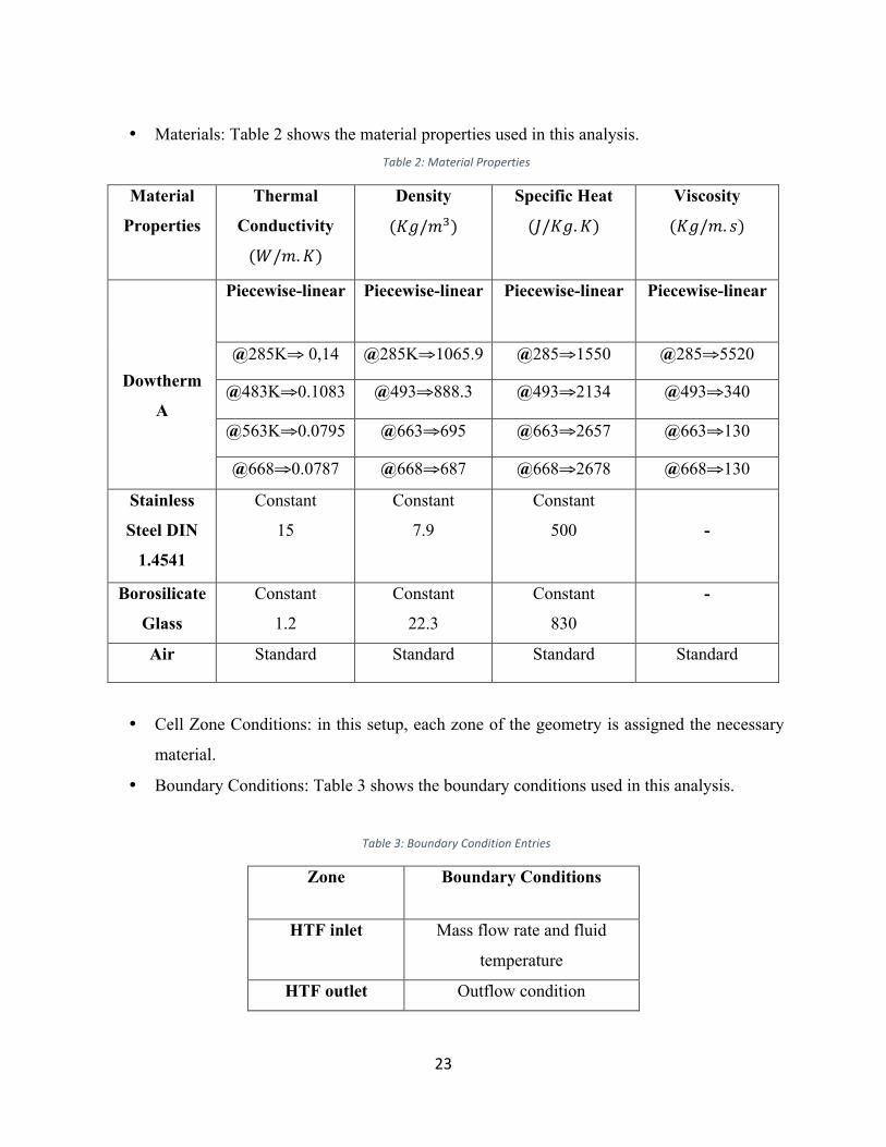
• Materials: Table 2 shows the material properties used in this analysis. Table2:MaterialProperties
Material
Properties
Thermal
Conductivity
(𝑊/𝑚.𝐾)
Density
(𝐾𝑔/𝑚@)
Specific Heat
(𝐽/𝐾𝑔. 𝐾)
Viscosity
(𝐾𝑔/𝑚. 𝑠)
Dowtherm
A
Piecewise-linear Piecewise-linear Piecewise-linear Piecewise-linear
@285K⇒ 0,14 @285K⇒1065.9 @285⇒1550 @285⇒5520
@483K⇒0.1083 @493⇒888.3 @493⇒2134 @493⇒340
@563K⇒0.0795 @663⇒695 @663⇒2657 @663⇒130
@668⇒0.0787 @668⇒687 @668⇒2678 @668⇒130
Stainless
Steel DIN
1.4541
Constant
15
Constant
7.9
Constant
500
-
Borosilicate
Glass
Constant
1.2
Constant
22.3
Constant
830
-
Air Standard Standard Standard Standard
• Cell Zone Conditions: in this setup, each zone of the geometry is assigned the necessary
material.
• Boundary Conditions: Table 3 shows the boundary conditions used in this analysis.
Table3:BoundaryConditionEntries
Zone Boundary Conditions
HTF inlet Mass flow rate and fluid
temperature
HTF outlet Outflow condition

24
Glass pipe wall No slip condition and heat flux
taken from solar load tracing
Steel pipe No slip condition and coupled
thermal condition
Wall part glass-
pipe vacuum
shadow
Coupled thermal condition
Wall part glass-
pipe vacuum
Coupled thermal condition
For Static Structural analysis: the results of the CFD analysis were imported in the physics setup
part of the structural analysis. All we had to do was to define which result parts of the design
should be imported. We selected two surfaces; the glass wall and the glass-vacuum shadow.
5.3.6 Numerical Solution
• Conjugate heat transfer-CFD analysis: before starting the calculation, we
initialized the problem, which is basically telling the software from where it should start its
calculations. The initialization was form HTF inlet. As a start we solved the problem with 200
iterations. Later on, the number of iterations will be changed using the method of solution
convergence. The governing equations used in this analysis are as following [13].
-Continuity equation
𝜕𝜌𝜕𝑡 + ∇. 𝜌𝑉 = 0
-Momentum conservation equation
𝜌𝐷𝑢𝐷𝑡 =
𝜕(𝜌𝑢)𝜕𝑡 + +∇. 𝜌𝑢𝑉
-Energy equation
𝜌𝐷𝑒𝐷𝑡 =
𝜕(𝜌𝑒)𝜕𝑡 + +∇. 𝜌𝑒𝑉
• Static Structural analysis: in this analysis, the stress option was used. The part of
the geometry selected for stress generation is the glass tube only.

25
5.3.7 Numerical Results
• Conjugate heat transfer-CFD analysis: in order to perceive the temperature contour, we
first designated a plane that takes into consideration all the parts of our design. This plane
is then fed to the contour to display the results. Fig 15 shows the temperature contour of
the glass casing in Kelvin. The maximum temperature generated on the glass envelope is
about 405℃.
Figure15:ConjugateHeatTransfer-CFDResults
• Structural analysis: The following picture (Fig 16) shows the stress generated in the glass
envelope due to thermal gradients.

26
Figure16:StaticStructuralResults
Interpretation:
According to the simulation conducted in ANSYS software, the thermal stress developed in the
glass casing reaches about 1400 MPa. Since the tensile strength of borosilicate glass is 280 MPa,
we can conclude that the thermal stress generated due to vacuum loss exceeds the tensile strength
of glass, and thus leads to its breakage.

27
6 Solution Design
6.1 Dynamic Vacuum
As proved in the previous chapter, losing vacuum in the annulus part leads to the glass envelope’s
breakage. The solution design suggested in this project is to implement a dynamic vacuum system
that will maintain the vacuum necessary for an efficient operation of HCEs.
The current design consists of making the vacuum only at the manufacturing process. For
maintenance, a getter system inside the vacuum zone is used. Its purpose is to absorb the gases
available in the vacuum. However, this system works only for low gas amounts, and is not
performant in case of serious leakage.
Our solution provides a more efficient and effective way for vacuum maintenance. We suggest that
HCEs should consist of continuous open chambers that will enable air elimination through the use
of a pumping system. The pumping system would be related to a very sensitive pressure probe that
ignites the pump to work in case of high pressure values, mainly beyond 10&@𝑚𝑏𝑎𝑟.
7 Limitations and Future Work
The Main limitation encountered in this capstone project was at the level of the software. We
have encountered software availability issues and license problems, in addition to computer
resources’ limitations. For example, one of our simulation trials took us two days to run, and a
warning message appeared as shown in Fig 17.
Figure17:ComputerLimitations

28
For future and follow-up work, we advise the use a performant machine.
Another important limitation encountered in this project is the inability to contact the HCE supplier,
Schott company, because of the disapproval of the company we are working with. It would have
been of great help if we were in contact with Schott’s research and development department.

29
8 Conclusion
This capstone project consisted of a theoretical and numerical analysis of HCE damage, in addition
to a solution design suggestion. The analysis part was mainly divided into three subparts. Design
related problems were analyzed, mainly glass-to-metal seal breakage, HTF cracking, aluminum
shield diffusivity. Also, possible operational problems were analyzed, mainly mass flow rate at
winter. Followed by a software analysis of vacuum loss. The simulation conducted in ANSYS
software is a coupled analysis, and is divided into two main parts. First, a conjugate heat transfer-
CFD analysis. Followed by a structural analysis. The results obtained in this analysis were the
temperature distribution and its resulted thermal stress across the glass tube. Via this simulation
we were able to prove that when vacuum is lost, the glass casing breaks. So, our solution design is
to implement a dynamic vacuum system that will maintain the required vacuum pressure for in the
annulus zone, avoid the HCE damage, and thus improve the overall efficiency of Noor 1 power
plant.

30
References [1] A. A. Hachicha, “Numerical modelling of a parabolic trough solar collector.” [2] M. Günther, M. Joemann, and S. Csambor, “Parabolic Trough Technology,” Advanced CSP Teaching Materials. [3] S. Ghadirijafarbeigloo, A. H. Zamzamian, and M. Yaghoubi, “3-D Numerical Simulation of Heat Transfer and Turbulent Flow in a Receiver Tube of Solar Parabolic Trough Concentrator with Louvered Twisted-tape Inserts,” Energy Procedia, vol. 49, pp. 373–380, 2014. [4] Z. F. Wang, Z. J. Wang, and D. Q. Lei, “Effects of Geometry and Material Properties on the
Residual Stress of Glass-to-metal Seals in Solar Receiver Tubes,” Energy Procedia, vol. 49, pp. 418–427, Jun. 2014.
[5] D. Lei, J. Li, and Z. Wang, “The calculation and analysis of glass-to-metal sealing stress in solar absorber tube,” Renewable Energy, vol. 35, no. 2, pp. 405–411, Feb. 2010. [6] M. Eck, J. F. Feldhoff, and R. Uhlig, “THERMAL MODELLING AND SIMULATION OF PARABOLIC TROUGH RECEIVER TUBES,” Proceedings of the ASME 2010 4th International Conference of Energy Sustainability, May 2010. [7]Y. B. Tao and Y. L. He, “Numerical study on coupled fluid flow and heat transfer process in parabolic trough solar collector tube,” Solar Energy, vol. 84, no. 10, pp. 1863–1872, Oct. 2010. [8]A. M. S. Bin Roslan and A. Salami Tijani, “Simulation Analysis of Thermal Losses of Parabolic trough Solar Collector in Malaysia Using Computational Fluid Dynamics,” Procedia Technology, vol. 15, pp. 841–848, 2014. [9]D. Lei, Z. Wang, and F. Du, “Proceedings of ISES World Congress 2007,” Proceedings of ISES World Congress 2007, vol. 1, pp. 740–744. [10]A. Y. Khaladkar and S. V. Kshirsagar, “Residual stress Measurement of Glass-to-Metal Seal in Solar Receiver Tube,” International Engineering Research Journal (IERJ), vol. 1, no. 7, pp. 522–528, 2015. [11] L. Moens and D. M. Blake, “MECHANISM OF HYDROGEN FORMATION IN SOLAR PARABOLIC TROUGH RECEIVERS,” 2008 14th Biennial CSP SolarPACES (Solar Power and Chemical Energy Systems) Symposium, 2008. [12] A. Y. Khaladkar and D. S. V. Kshirsagar, “Optimization of Glass-to-Metal Sealsin Solar Receiver Tubes,” International Engineering Research Journal (IERJ), no. 2, pp. 5459–5465.

31
[13] “ANSYS Fluent Theory Guide.” [14] “ANSYS Mechanical User's Guide.”