Embed Size (px)
Citation preview

Structural Stainless Steel Case Study 10 Page 1
Structural Stainless Steel
Case Study 10
Schubert Club Band Shell The Schubert Club Band Shell is an outdoor venue for performing arts on Raspberry Island, in the middle of the Mississippi River in St Paul, Minnesota. It was commissioned by the Schubert Club and completed in 2002. The island had been neglected for many years before the Band Shell was built but now offers generous pedestrian walkways, unique and scenic vistas as well as a central location. The structure itself is saddle-shaped (anticlastic) and brings together concrete, wood, stainless steel and laminated glass to create a functional space. The design team developed a 7.6 m wide stainless steel lattice grid that spans 15.2 m between precast concrete abutments and covers a wood-framed stage. Acid-etched glass is offset from and supported by the lattice.
Material Selection
Figure 1: General view of Schubert Club Band Shell
The overall design was influenced by the surrounding area which is subject to
flooding as well as deicing salts. This precluded the use of closed shapes and
also meant that the structure needed to be corrosion resistant. Furthermore, it
needed to have a robust base in order to resist impact from flood-borne debris.
These factors, coupled with the desire to create a low-maintenance but
architecturally significant structure, led the designers to choose stainless steel
for the lattice. The Schubert Club hoped for a unique structure that would draw
people to the island and establish the area as an important public venue.
All lattice components as well as the interface plates are made from austenitic
grades 1.4404 (S31603) and 1.4301 (S30400). Stiffening beams, also made
from grade 1.4404, are used at the edges of the lattice. These grades were
selected due to concerns about the material coming into contact with airborne
deicing salts from adjacent overhead roadways. De-icing salts contain
chlorides that may cause lower alloyed grades of stainless steel to corrode.
Figure 2: View of the stainless steel members and node point in the band shell (Photo: James Carpenter Design Associates and Shane McCormick)
Schubert Club Band Shell
Structural Stainless Steel Case Study 10 Page 2
Figure 3: The Band Shell was first put assembled in the fabricators car park to ensure a good fit-up (Photo: Tim Eliassen)
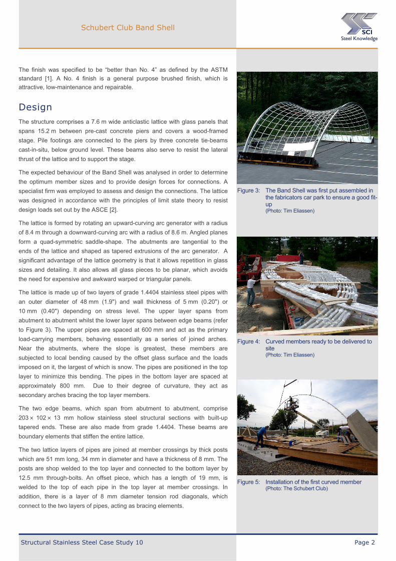
Figure 4: Curved members ready to be delivered to site (Photo: Tim Eliassen)
The finish was specified to be “better than No. 4” as defined by the ASTM
standard [1]. A No. 4 finish is a general purpose brushed finish, which is
attractive, low-maintenance and repairable.
Design The structure comprises a 7.6 m wide anticlastic lattice with glass panels that
spans 15.2 m between pre-cast concrete piers and covers a wood-framed
stage. Pile footings are connected to the piers by three concrete tie-beams
cast-in-situ, below ground level. These beams also serve to resist the lateral
thrust of the lattice and to support the stage.
The expected behaviour of the Band Shell was analysed in order to determine
the optimum member sizes and to provide design forces for connections. A
specialist firm was employed to assess and design the connections. The lattice
was designed in accordance with the principles of limit state theory to resist
design loads set out by the ASCE [2].
The lattice is formed by rotating an upward-curving arc generator with a radius
of 8.4 m through a downward-curving arc with a radius of 8.6 m. Angled planes
form a quad-symmetric saddle-shape. The abutments are tangential to the
ends of the lattice and shaped as tapered extrusions of the arc generator. A
significant advantage of the lattice geometry is that it allows repetition in glass
sizes and detailing. It also allows all glass pieces to be planar, which avoids
the need for expensive and awkward warped or triangular panels.
The lattice is made up of two layers of grade 1.4404 stainless steel pipes with
an outer diameter of 48 mm (1.9") and wall thickness of 5 mm (0.20") or
10 mm (0.40") depending on stress level. The upper layer spans from
abutment to abutment whilst the lower layer spans between edge beams (refer
to Figure 3). The upper pipes are spaced at 600 mm and act as the primary
load-carrying members, behaving essentially as a series of joined arches.
Near the abutments, where the slope is greatest, these members are
subjected to local bending caused by the offset glass surface and the loads
imposed on it, the largest of which is snow. The pipes are positioned in the top
layer to minimize this bending. The pipes in the bottom layer are spaced at
approximately 800 mm. Due to their degree of curvature, they act as
secondary arches bracing the top layer members.
The two edge beams, which span from abutment to abutment, comprise
203 102 13 mm hollow stainless steel structural sections with built-up
tapered ends. These are also made from grade 1.4404. These beams are
boundary elements that stiffen the entire lattice.
The two lattice layers of pipes are joined at member crossings by thick posts
which are 51 mm long, 34 mm in diameter and have a thickness of 8 mm. The
posts are shop welded to the top layer and connected to the bottom layer by
12.5 mm through-bolts. An offset piece, which has a length of 19 mm, is
welded to the top of each pipe in the top layer at member crossings. In
addition, there is a layer of 8 mm diameter tension rod diagonals, which
connect to the two layers of pipes, acting as bracing elements.
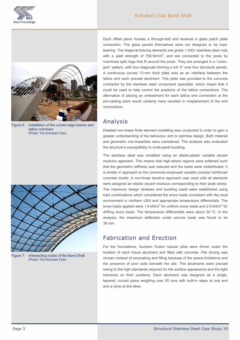
Figure 5: Installation of the first curved member (Photo: The Schubert Club)
Schubert Club Band Shell
Page 3 Structural Stainless Steel Case Study 10
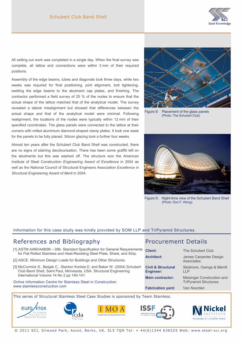
Figure 6: Installation of the curved edge beams and lattice members (Photo: The Schubert Club)
Figure 7: Intersecting nodes of the Band Shell (Photo: The Schubert Club)
Each offset piece houses a through-bolt and receives a glass patch plate
connection. The glass panels themselves were not designed to be load-
bearing. The diagonal bracing elements are grade 1.4301 stainless steel rods
with a yield strength of 758 N/mm2, and are connected to the posts by
machined split rings that fit around the posts. They are arranged in a “union-
jack” pattern, with four diagonals forming a full ‘X’ over four structural panels.
A continuous curved 13 mm thick plate acts as an interface between the
lattice and each precast abutment. This plate was provided to the concrete
contractor by the stainless steel component specialist, which meant that it
could be used to help control the positions of the lattice connections. The
alternative of placing an embedment for each lattice end connection at the
pre-casting plant would certainly have resulted in misplacement of the end
connections.
Analysis Detailed non-linear finite element modelling was conducted in order to gain a
greater understanding of the behaviour and to optimise design. Both material
and geometric non-linearities were considered. The analysis also evaluated
the structure’s susceptibility to multi-panel buckling.
The stainless steel was modelled using an elasto-plastic variable secant
modulus approach. This means that high-stress regions were softened such
that the geometric stiffness was reduced and the loads were redistributed. It
is similar in approach to the commonly-employed variable cracked reinforced
concrete model. A non-linear iterative approach was used until all elements
were assigned an elastic secant modulus corresponding to their peak stress.
The maximum design stresses and buckling loads were established using
load combinations which considered the snow loads consistent with the local
environment in northern USA and appropriate temperature differentials. The
snow loads applied were 1.9 kN/m2 for uniform snow loads and 2.9 kN/m2 for
drifting snow loads. The temperature differentials were about 50 °C. In the
analysis, the maximum deflection under service loads was found to be
38 mm.
Fabrication and Erection For the foundations, fourteen friction tubular piles were driven under the
location of each future abutment and filled with concrete. Pile driving was
chosen instead of excavating and filling because of the space limitations and
the presence of poor soils beneath the site. The abutments were precast
owing to the high standards required for the surface appearance and the tight
tolerance on their positions. Each abutment was designed as a single,
tapered, curved piece weighing over 50 tons with built-in steps at one end
and a ramp at the other.
Schubert Club Band Shell
All setting out work was completed in a single day. When the final survey was
complete, all lattice end connections were within 3 mm of their required
positions.
Assembly of the edge beams, tubes and diagonals took three days, while two
weeks was required for final positioning, joint alignment, bolt tightening,
welding the edge beams to the abutment cap plates, and finishing. The
contractor performed a field survey of 25 % of the nodes to ensure that the
actual shape of the lattice matched that of the analytical model. The survey
revealed a lateral misalignment but showed that differences between the
actual shape and that of the analytical model were minimal. Following
realignment, the locations of the nodes were typically within 12 mm of their
specified coordinates. The glass panels were connected to the lattice at their
corners with milled aluminium diamond-shaped clamp plates. It took one week
for the panels to be fully placed. Silicon glazing took a further four weeks.
Almost ten years after the Schubert Club Band Shell was constructed, there
are no signs of staining decolourisation. There has been some graffiti left on
the abutments but this was washed off. The structure won the American
Institute of Steel Construction Engineering Award of Excellence in 2004 as
well as the National Council of Structural Engineers Association Excellence in
Structural Engineering Award of Merit in 2004.
Figure 8: Placement of the glass panels (Photo: The Schubert Club)
Figure 9: Night-time view of the Schubert Band Shell(Photo: Don F. Wong)
Information for this case study was kindly provided by SOM LLP and TriPyramid Structures.
References and Bibliography [1] ASTM A480/A480M – 09b. Standard Specification for General Requirements
for Flat Rolled Stainless and Heat-Resisting Steel Plate, Sheet, and Strip.
[2] ASCE. Minimum Design Loads for Buildings and Other Structures.
[3] McCormick S., Besjak C., Stanton Korista D. and Baker W. (2004) Schubert Club Band Shell, Saint Paul, Minnesota, USA. Structural Engineering International Volume 14 No 2 pp 140-141.
Online Information Centre for Stainless Steel in Construction: www.stainlessconstruction.com
Procurement Details Client: The Schubert Club
Architect: James Carpenter Design Associates
Civil & Structural Engineer:
Skidmore, Owings & Merrill LLP
Main contractor: Meisinger Construction and TriPyramid Structures.
Fabrication yard: Van Noorden
This series of Structural Stainless Steel Case Studies is sponsored by Team Stainless.
© 2011 SCI, S i lwood Park, Ascot , Berks, UK, SL5 7QN Tel: + 44(0)1344 636525 Web: www.stee l-sc i .org


![ZZZ MD]HHUDEROWV FRP DGPLQ#MD]HHUDEROWV …superduplexfastener.com/tech-info/mechanical-chemical/Nickel Alloys... · uns (341400 g41400 g43400 s30400 s30400 s32100 ... alloy and stainless](https://img.pdfslide.net/doc/110x75/5ae818bd7f8b9a8b2b8f83dc/zzz-mdhhuderowv-frp-dgplqmdhhuderowv-alloysuns-341400-g41400-g43400-s30400.jpg)