Embed Size (px)
Citation preview
®
Schwefel Nitratfilter
Sulphur Nitrate Filter
Filtri denitratori a zolfo
Bedienungsanleitungen und Ersatzteillisten
Operating instructions
and Spare parts lists
Istruzioni d‘uso e parti di ricambio
DE
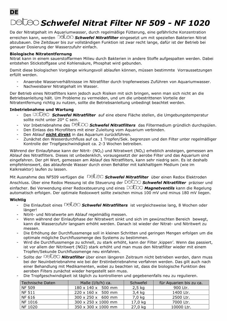
Schwefel Nitrat Filter NF 509 - NF 1020
Da der Nitratgehalt im Aquariumwasser, durch regelmäßige Fütterung, eine gefährliche Konzentration
erreichen kann, werden
Schwefel Nitratfilter eingesetzt um mit speziellen Bakterien Nitrat abzubauen. Die Zeitdauer bis zur vollständigen Funktion ist zwar recht lange, dafür ist der Betrieb bei genauer Dosierung der Wasserzufuhr einfach.
Biologische Nitratentfernung Nitrat kann in einem sauerstoffarmen Milieu durch Bakterien in andere Stoffe aufgespalten werden. Dabei entstehen Stickstoffgase und Kohlensäure, Phosphat wird gebunden.
Damit diese biologischen Vorgänge wirkungsvoll ablaufen können, müssen bestimmte Vorraussetzungen erfüllt werden.
- Anaerobe Wasserverhältnissse im Nitratfilter durch tropfenweises Zuführen von Aquariumwasser. - Nachweisbarer Nitratgehalt im Wasser.
Der Betrieb eines Nitratfilters kann jedoch auch Risiken mit sich bringen, wenn man sich nicht an die Betriebsanleitung hält. Um Probleme zu vermeiden, und um die unbestrittenen Vorteile der Nitratentfernung richtig zu nutzen, sollte die Betriebsanleitung unbedingt beachtet werden.
Inbetriebnahme und Wartung
- Den
Schwefel Nitratfilter auf eine ebene Fläche stellen, die Umgebungstemperatur sollte nicht unter 20° C sein.
- Vor Inbetriebnahme des
Schwefel Nitratfilters das Filtermedium gründlich durchspülen. - Den Einlass des Microfilters mit einer Zuleitung vom Aquarium verbinden. - Den Ablauf nicht direkt in das Aquarium zurückführen. - Zunächst den Wasserdurchfluss auf ca. 1 Tropfen/Sek. begrenzen und den Filter unter regelmäßiger
Kontrolle der Tropfgeschwindigkeit ca. 2-3 Wochen betreiben.
Während der Einlaufphase kann der Nitrit- (NO2) und Nitratwert (NO3) erheblich ansteigen, gemessen am Ablauf des Nitratfilters. Dieses ist unbedenklich, vorausgesetzt der aerobe Filter und das Aquarium sind eingefahren. Der pH Wert, gemessen am Ablauf des Nitratfilters, kann sehr niedrig sein. Es ist deshalb empfehlenswert, das ablaufende Wasser durch einen Behälter mit kalkhaltigem Medium (wie im Kalkreaktor) laufen zu lassen.
Mit Ausnahme des NF509 verfügen die
Schwefel Nitratfilter über einen Redox Elektroden
Anschluss. Über eine Redox Messung ist die Steuerung der
Schwefel Nitratfilter präziser und
einfacher. Bei Verwendung einer Redoxsteuerung und eines
Magnetventils kann die Regelung automatisch erfolgen. Der optimale Redoxwert sollte zwischen minus 100 mV und minus 180 mV liegen.
Wichtig
- Die Einlaufzeit eines
Schwefel Nitratfilters ist vergleichsweise lang, 8 Wochen oder länger!
- Nitrit- und Nitratwerte am Ablauf regelmäßig messen. - Wenn während der Einlaufphase der Nitratwert sinkt und sich im gewünschten Bereich bewegt,
kann die Wasserzufuhr langsam erhöht werden. Danach ist wieder der Nitrat- und Nitritwert zu messen.
- Die Erhöhung der Durchflussmenge soll in kleinen Schritten und geringen Mengen erfolgen um die optimale mögliche Durchflussmenge des Systems zu bestimmen.
- Wird die Durchflussmenge zu schnell, zu stark erhöht, kann der Filter ‚kippen’. Wenn das passiert, ist vor allem der Nitritwert (NO2) stark erhöht und man muss den Nitratfilter wieder mit einem Tropfen/Sekunde Durchflussmenge neu einfahren.
- Sollte der Nitratfilter über einen längeren Zeitraum nicht betrieben werden, dann muss bei der Neuinbetriebnahme wie bei der Erstinbetriebnahme verfahren werden. Das gilt auch nach einer Behandlung mit Medikamenten, wobei zu beachten ist, dass die biologische Funktion des aeroben Filters zunächst wieder hergestellt sein muss.
- Die Tropfgeschwindigkeit ist täglich zu kontrollieren und gegebenenfalls neu zu regulieren.
Technische Daten Maße (l/b/h) ca. Schwefel für Aquarien bis zu ca. NF 509 180 x 140 x 500 mm 2,5 kg 900 Ltr. NF 511 220 x 160 x 500 mm 3,4 kg 1400 Ltr. NF 616 300 x 250 x 600 mm 7,0 kg 2500 Ltr. NF 1016 300 x 250 x 1000 mm 17,0 kg 7000 Ltr. NF 1020 350 x 300 x 1000 mm 27,0 kg 10000 Ltr.
EN
Sulphur Nitrate Filter NF 509 - NF 1020
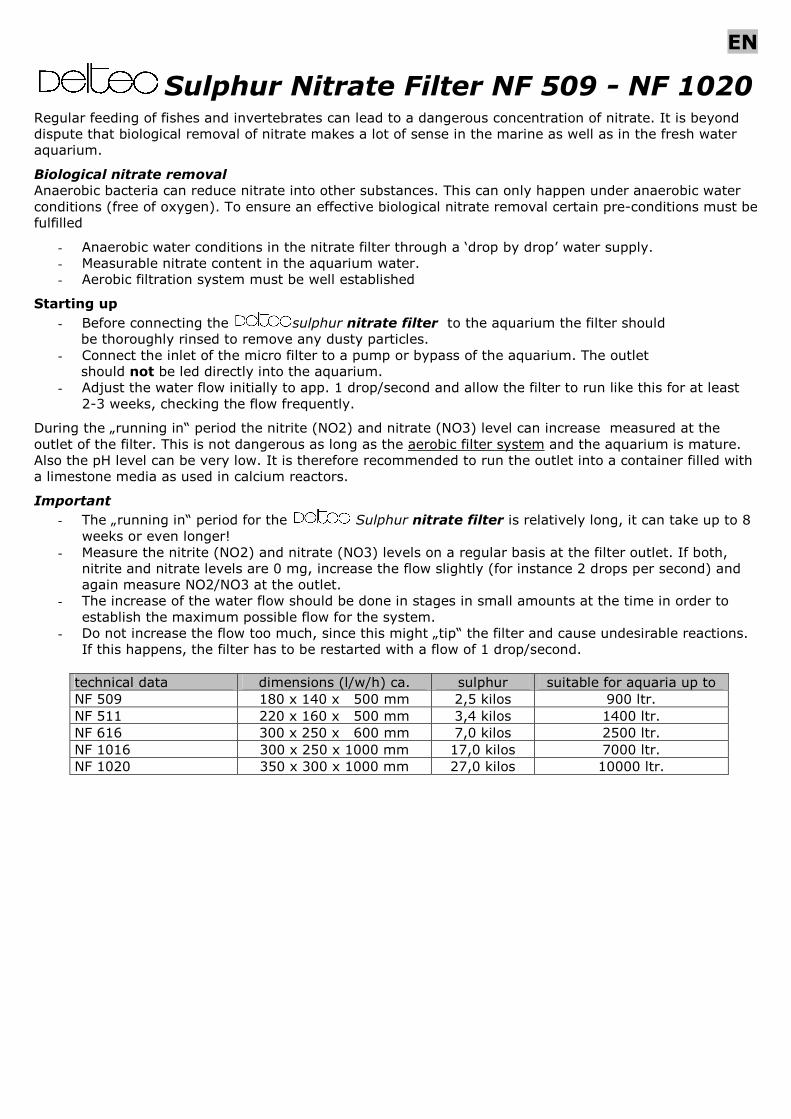
Regular feeding of fishes and invertebrates can lead to a dangerous concentration of nitrate. It is beyond dispute that biological removal of nitrate makes a lot of sense in the marine as well as in the fresh water aquarium.
Biological nitrate removal
Anaerobic bacteria can reduce nitrate into other substances. This can only happen under anaerobic water conditions (free of oxygen). To ensure an effective biological nitrate removal certain pre-conditions must be fulfilled
- Anaerobic water conditions in the nitrate filter through a ‘drop by drop’ water supply. - Measurable nitrate content in the aquarium water. - Aerobic filtration system must be well established
Starting up
- Before connecting the sulphur nitrate filter to the aquarium the filter should be thoroughly rinsed to remove any dusty particles.
- Connect the inlet of the micro filter to a pump or bypass of the aquarium. The outlet should not be led directly into the aquarium.
- Adjust the water flow initially to app. 1 drop/second and allow the filter to run like this for at least 2-3 weeks, checking the flow frequently.
During the „running in“ period the nitrite (NO2) and nitrate (NO3) level can increase measured at the outlet of the filter. This is not dangerous as long as the aerobic filter system and the aquarium is mature. Also the pH level can be very low. It is therefore recommended to run the outlet into a container filled with a limestone media as used in calcium reactors.
Important
- The „running in“ period for the Sulphur nitrate filter is relatively long, it can take up to 8 weeks or even longer!
- Measure the nitrite (NO2) and nitrate (NO3) levels on a regular basis at the filter outlet. If both, nitrite and nitrate levels are 0 mg, increase the flow slightly (for instance 2 drops per second) and again measure NO2/NO3 at the outlet.
- The increase of the water flow should be done in stages in small amounts at the time in order to establish the maximum possible flow for the system.
- Do not increase the flow too much, since this might „tip“ the filter and cause undesirable reactions. If this happens, the filter has to be restarted with a flow of 1 drop/second.
technical data dimensions (l/w/h) ca. sulphur suitable for aquaria up to NF 509 180 x 140 x 500 mm 2,5 kilos 900 ltr. NF 511 220 x 160 x 500 mm 3,4 kilos 1400 ltr. NF 616 300 x 250 x 600 mm 7,0 kilos 2500 ltr. NF 1016 300 x 250 x 1000 mm 17,0 kilos 7000 ltr. NF 1020 350 x 300 x 1000 mm 27,0 kilos 10000 ltr.
IT
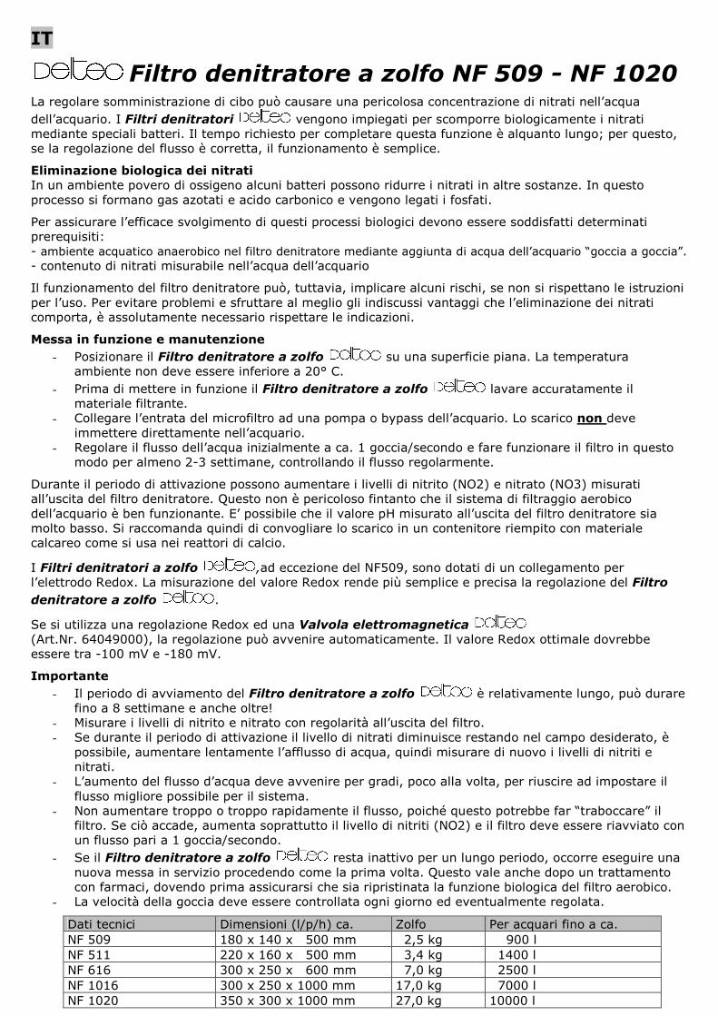
Filtro denitratore a zolfo NF 509 - NF 1020
La regolare somministrazione di cibo può causare una pericolosa concentrazione di nitrati nell’acqua
dell’acquario. I Filtri denitratori
vengono impiegati per scomporre biologicamente i nitrati mediante speciali batteri. Il tempo richiesto per completare questa funzione è alquanto lungo; per questo, se la regolazione del flusso è corretta, il funzionamento è semplice.
Eliminazione biologica dei nitrati In un ambiente povero di ossigeno alcuni batteri possono ridurre i nitrati in altre sostanze. In questo processo si formano gas azotati e acido carbonico e vengono legati i fosfati.
Per assicurare l’efficace svolgimento di questi processi biologici devono essere soddisfatti determinati prerequisiti: - ambiente acquatico anaerobico nel filtro denitratore mediante aggiunta di acqua dell’acquario “goccia a goccia”. - contenuto di nitrati misurabile nell’acqua dell’acquario
Il funzionamento del filtro denitratore può, tuttavia, implicare alcuni rischi, se non si rispettano le istruzioni per l’uso. Per evitare problemi e sfruttare al meglio gli indiscussi vantaggi che l’eliminazione dei nitrati comporta, è assolutamente necessario rispettare le indicazioni.
Messa in funzione e manutenzione
- Posizionare il Filtro denitratore a zolfo
su una superficie piana. La temperatura ambiente non deve essere inferiore a 20° C.
- Prima di mettere in funzione il Filtro denitratore a zolfo
lavare accuratamente il materiale filtrante.
- Collegare l’entrata del microfiltro ad una pompa o bypass dell’acquario. Lo scarico non deve immettere direttamente nell’acquario.
- Regolare il flusso dell’acqua inizialmente a ca. 1 goccia/secondo e fare funzionare il filtro in questo modo per almeno 2-3 settimane, controllando il flusso regolarmente.
Durante il periodo di attivazione possono aumentare i livelli di nitrito (NO2) e nitrato (NO3) misurati all’uscita del filtro denitratore. Questo non è pericoloso fintanto che il sistema di filtraggio aerobico dell’acquario è ben funzionante. E’ possibile che il valore pH misurato all’uscita del filtro denitratore sia molto basso. Si raccomanda quindi di convogliare lo scarico in un contenitore riempito con materiale calcareo come si usa nei reattori di calcio.
I Filtri denitratori a zolfo
,ad eccezione del NF509, sono dotati di un collegamento per l’elettrodo Redox. La misurazione del valore Redox rende più semplice e precisa la regolazione del Filtro
denitratore a zolfo
.
Se si utilizza una regolazione Redox ed una Valvola elettromagnetica
(Art.Nr. 64049000), la regolazione può avvenire automaticamente. Il valore Redox ottimale dovrebbe essere tra -100 mV e -180 mV.
Importante
- Il periodo di avviamento del Filtro denitratore a zolfo
è relativamente lungo, può durare fino a 8 settimane e anche oltre!
- Misurare i livelli di nitrito e nitrato con regolarità all’uscita del filtro. - Se durante il periodo di attivazione il livello di nitrati diminuisce restando nel campo desiderato, è
possibile, aumentare lentamente l’afflusso di acqua, quindi misurare di nuovo i livelli di nitriti e nitrati.
- L’aumento del flusso d’acqua deve avvenire per gradi, poco alla volta, per riuscire ad impostare il flusso migliore possibile per il sistema.
- Non aumentare troppo o troppo rapidamente il flusso, poiché questo potrebbe far “traboccare” il filtro. Se ciò accade, aumenta soprattutto il livello di nitriti (NO2) e il filtro deve essere riavviato con un flusso pari a 1 goccia/secondo.
- Se il Filtro denitratore a zolfo resta inattivo per un lungo periodo, occorre eseguire una nuova messa in servizio procedendo come la prima volta. Questo vale anche dopo un trattamento con farmaci, dovendo prima assicurarsi che sia ripristinata la funzione biologica del filtro aerobico.
- La velocità della goccia deve essere controllata ogni giorno ed eventualmente regolata.
Dati tecnici Dimensioni (l/p/h) ca. Zolfo Per acquari fino a ca. NF 509 180 x 140 x 500 mm 2,5 kg 900 l NF 511 220 x 160 x 500 mm 3,4 kg 1400 l NF 616 300 x 250 x 600 mm 7,0 kg 2500 l NF 1016 300 x 250 x 1000 mm 17,0 kg 7000 l NF 1020 350 x 300 x 1000 mm 27,0 kg 10000 l
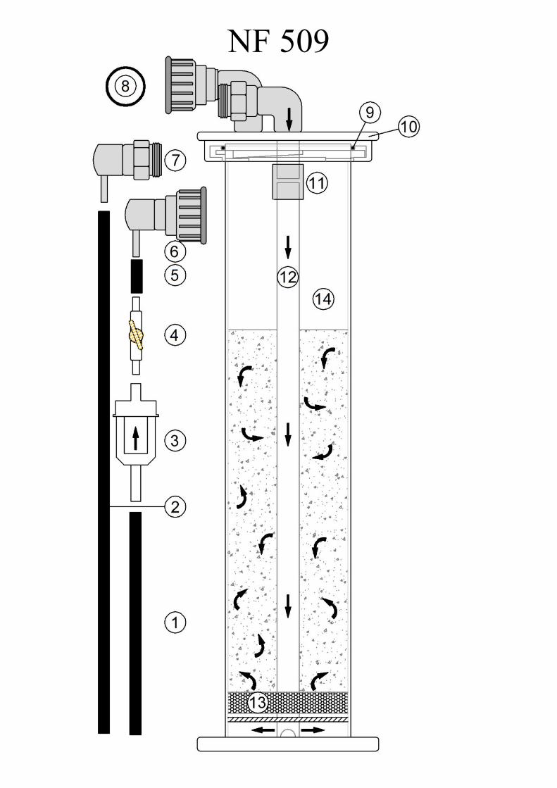
NF 509
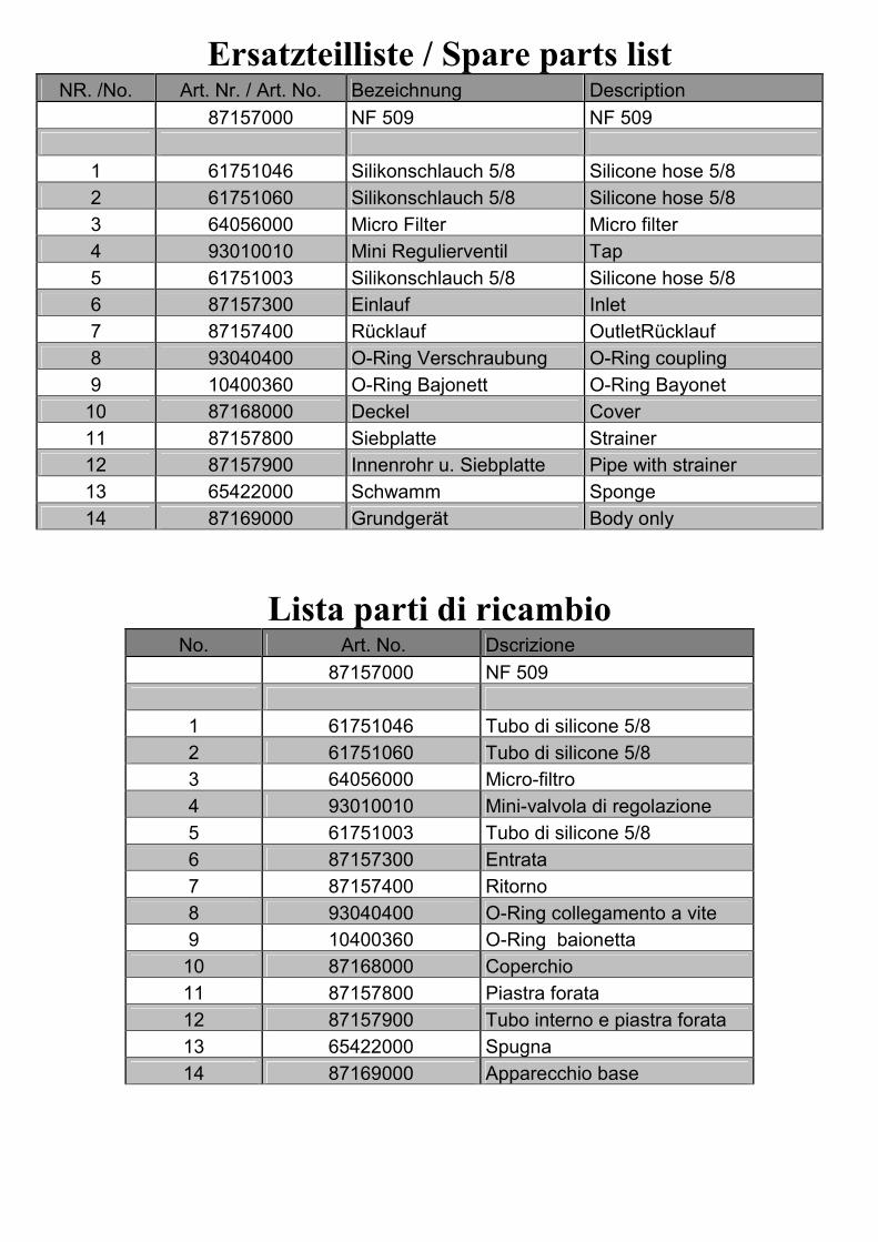
Ersatzteilliste / Spare parts list NR. /No. Art. Nr. / Art. No. Bezeichnung Description
87157000 NF 509 NF 509
1 61751046 Silikonschlauch 5/8 Silicone hose 5/8
2 61751060 Silikonschlauch 5/8 Silicone hose 5/8
3 64056000 Micro Filter Micro filter
4 93010010 Mini Regulierventil Tap
5 61751003 Silikonschlauch 5/8 Silicone hose 5/8
6 87157300 Einlauf Inlet
7 87157400 Rücklauf OutletRücklauf
8 93040400 O-Ring Verschraubung O-Ring coupling
9 10400360 O-Ring Bajonett O-Ring Bayonet
10 87168000 Deckel Cover
11 87157800 Siebplatte Strainer
12 87157900 Innenrohr u. Siebplatte Pipe with strainer
13 65422000 Schwamm Sponge
14 87169000 Grundgerät Body only
Lista parti di ricambio No. Art. No. Dscrizione
87157000 NF 509
1 61751046 Tubo di silicone 5/8
2 61751060 Tubo di silicone 5/8
3 64056000 Micro-filtro
4 93010010 Mini-valvola di regolazione
5 61751003 Tubo di silicone 5/8
6 87157300 Entrata
7 87157400 Ritorno
8 93040400 O-Ring collegamento a vite
9 10400360 O-Ring baionetta
10 87168000 Coperchio
11 87157800 Piastra forata
12 87157900 Tubo interno e piastra forata
13 65422000 Spugna
14 87169000 Apparecchio base
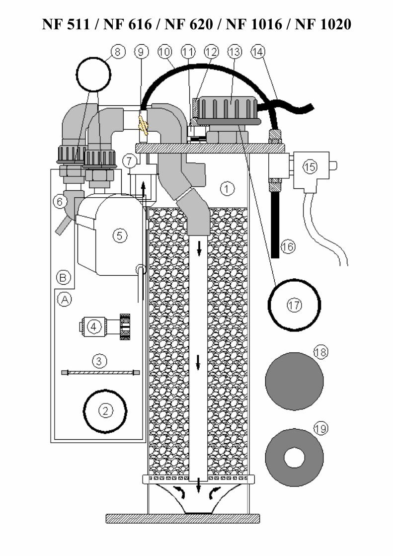
NF 511 / NF 616 / NF 620 / NF 1016 / NF 1020
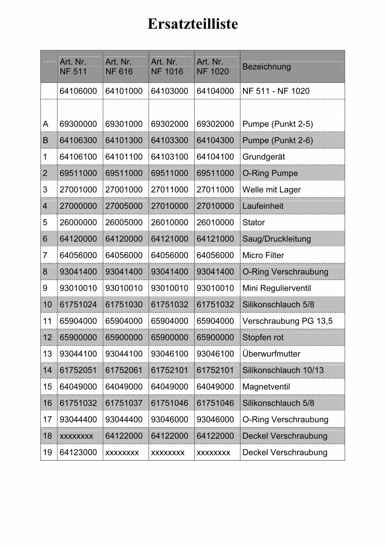
Ersatzteilliste
Art. Nr. NF 511
Art. Nr. NF 616
Art. Nr. NF 1016
Art. Nr. NF 1020
Bezeichnung
64106000 64101000 64103000 64104000 NF 511 - NF 1020
A 69300000 69301000 69302000 69302000 Pumpe (Punkt 2-5)
B 64106300 64101300 64103300 64104300 Pumpe (Punkt 2-6)
1 64106100 64101100 64103100 64104100 Grundgerät
2 69511000 69511000 69511000 69511000 O-Ring Pumpe
3 27001000 27001000 27011000 27011000 Welle mit Lager
4 27000000 27005000 27010000 27010000 Laufeinheit
5 26000000 26005000 26010000 26010000 Stator
6 64120000 64120000 64121000 64121000 Saug/Druckleitung
7 64056000 64056000 64056000 64056000 Micro Filter
8 93041400 93041400 93041400 93041400 O-Ring Verschraubung
9 93010010 93010010 93010010 93010010 Mini Regulierventil
10 61751024 61751030 61751032 61751032 Silikonschlauch 5/8
11 65904000 65904000 65904000 65904000 Verschraubung PG 13,5
12 65900000 65900000 65900000 65900000 Stopfen rot
13 93044100 93044100 93046100 93046100 Überwurfmutter
14 61752051 61752061 61752101 61752101 Silikonschlauch 10/13
15 64049000 64049000 64049000 64049000 Magnetventil
16 61751032 61751037 61751046 61751046 Silikonschlauch 5/8
17 93044400 93044400 93046000 93046000 O-Ring Verschraubung
18 xxxxxxxx 64122000 64122000 64122000 Deckel Verschraubung
19 64123000 xxxxxxxx xxxxxxxx xxxxxxxx Deckel Verschraubung
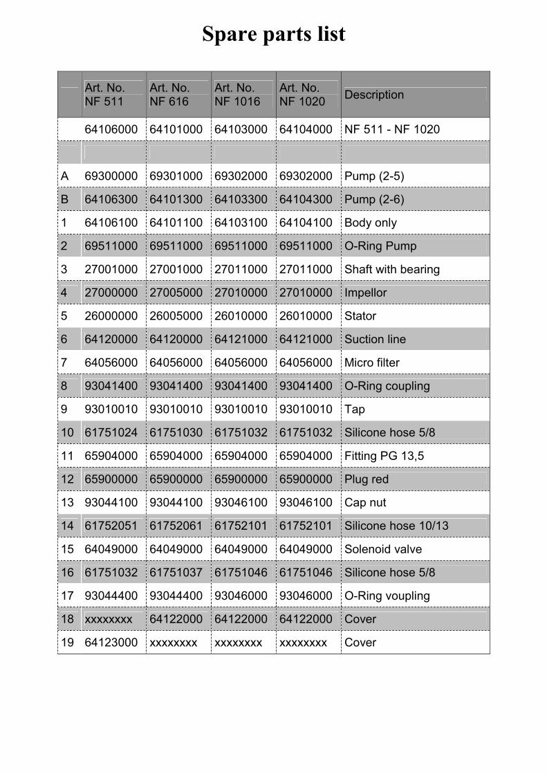
Spare parts list
Art. No. NF 511
Art. No. NF 616
Art. No. NF 1016
Art. No. NF 1020
Description
64106000 64101000 64103000 64104000 NF 511 - NF 1020
A 69300000 69301000 69302000 69302000 Pump (2-5)
B 64106300 64101300 64103300 64104300 Pump (2-6)
1 64106100 64101100 64103100 64104100 Body only
2 69511000 69511000 69511000 69511000 O-Ring Pump
3 27001000 27001000 27011000 27011000 Shaft with bearing
4 27000000 27005000 27010000 27010000 Impellor
5 26000000 26005000 26010000 26010000 Stator
6 64120000 64120000 64121000 64121000 Suction line
7 64056000 64056000 64056000 64056000 Micro filter
8 93041400 93041400 93041400 93041400 O-Ring coupling
9 93010010 93010010 93010010 93010010 Tap
10 61751024 61751030 61751032 61751032 Silicone hose 5/8
11 65904000 65904000 65904000 65904000 Fitting PG 13,5
12 65900000 65900000 65900000 65900000 Plug red
13 93044100 93044100 93046100 93046100 Cap nut
14 61752051 61752061 61752101 61752101 Silicone hose 10/13
15 64049000 64049000 64049000 64049000 Solenoid valve
16 61751032 61751037 61751046 61751046 Silicone hose 5/8
17 93044400 93044400 93046000 93046000 O-Ring voupling
18 xxxxxxxx 64122000 64122000 64122000 Cover
19 64123000 xxxxxxxx xxxxxxxx xxxxxxxx Cover
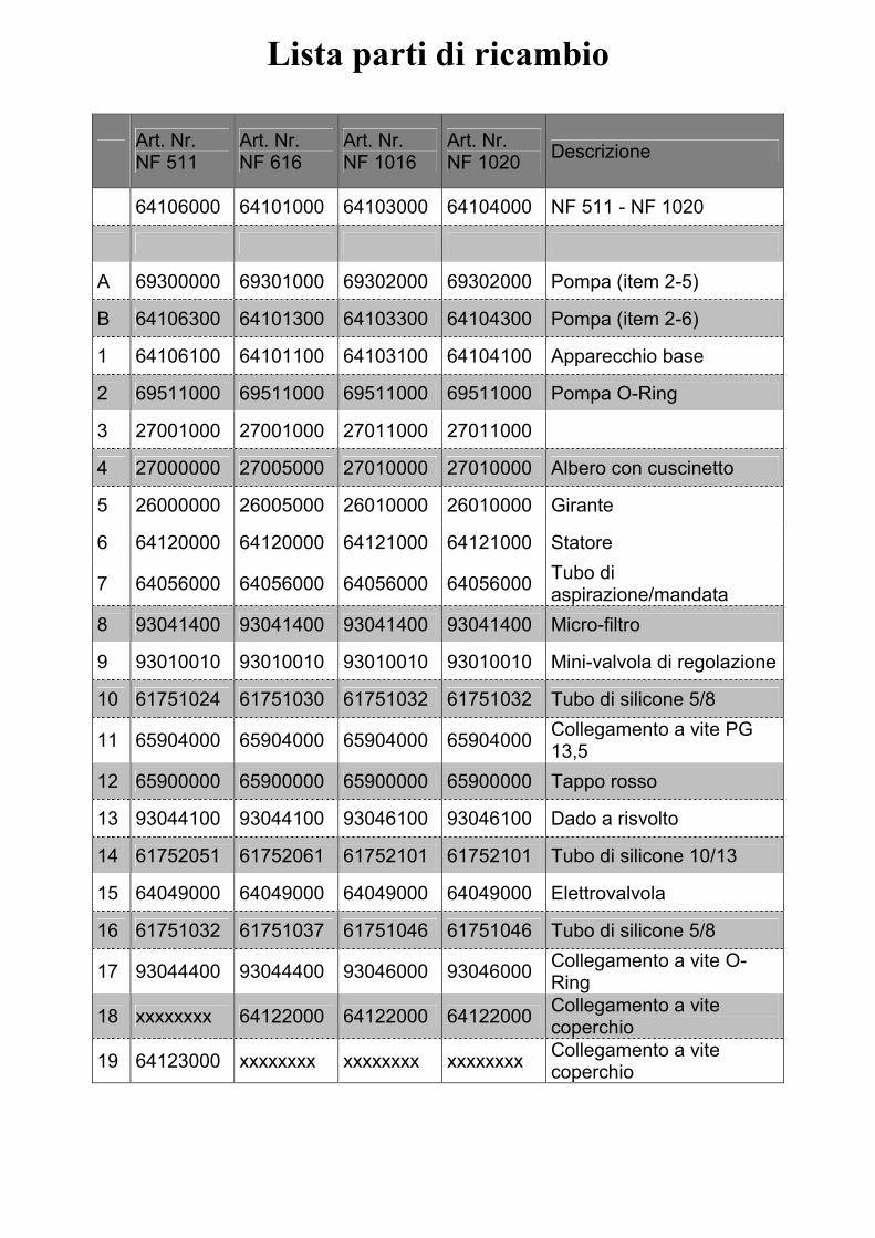
Lista parti di ricambio
Art. Nr. NF 511
Art. Nr. NF 616
Art. Nr. NF 1016
Art. Nr. NF 1020
Descrizione
64106000 64101000 64103000 64104000 NF 511 - NF 1020
A 69300000 69301000 69302000 69302000 Pompa (item 2-5)
B 64106300 64101300 64103300 64104300 Pompa (item 2-6)
1 64106100 64101100 64103100 64104100 Apparecchio base
2 69511000 69511000 69511000 69511000 Pompa O-Ring
3 27001000 27001000 27011000 27011000
4 27000000 27005000 27010000 27010000 Albero con cuscinetto
5 26000000 26005000 26010000 26010000 Girante
6 64120000 64120000 64121000 64121000 Statore
7 64056000 64056000 64056000 64056000 Tubo di aspirazione/mandata
8 93041400 93041400 93041400 93041400 Micro-filtro
9 93010010 93010010 93010010 93010010 Mini-valvola di regolazione
10 61751024 61751030 61751032 61751032 Tubo di silicone 5/8
11 65904000 65904000 65904000 65904000 Collegamento a vite PG 13,5
12 65900000 65900000 65900000 65900000 Tappo rosso
13 93044100 93044100 93046100 93046100 Dado a risvolto
14 61752051 61752061 61752101 61752101 Tubo di silicone 10/13
15 64049000 64049000 64049000 64049000 Elettrovalvola
16 61751032 61751037 61751046 61751046 Tubo di silicone 5/8
17 93044400 93044400 93046000 93046000 Collegamento a vite O-Ring
18 xxxxxxxx 64122000 64122000 64122000 Collegamento a vite coperchio
19 64123000 xxxxxxxx xxxxxxxx xxxxxxxx Collegamento a vite coperchio

Deltec GmbH Steller Straße 75
D-27755 Delmenhorst
Deutschland / Germany www.deltec-aquaristic.com
Deltec GmbH 2016