Embed Size (px)
Citation preview
Wegener International GmbH Vaalser Str. 81 D-52074 Aachen [email protected]
2
Welding of Thermoplastics
Preface about Thermoplastic Welding
Compared to other plastics such as thermoset and elastomer, thermoplastics have the advantage to melt through heat exposure. They become plastically capable of flow and can be welded. Other than rivet, screw or similar connections, welds provide impermeable compounds with often even, smooth surfaces without notch effects and uniform tension distribution. Thus the do-it-yourself man won‟t miss out on this sealing potential. Just a few examples:
Polyethylene: Rain water tanks, pond sheeting, cans
Polypropylene: Garden furniture, waste water pipes, household bins (buckets, baskets)
PVC: Pond sheeting, waste water pipes, eaves gutters
ABS: Jet bags, bike body parts
But the do-it-yourself man also wants to assemble boxes and basins etc. from sheet material pre-cut parts. Or, he needs to weld joints of stair handrails or connect PVC floor tiles or PVC sheets impermeably. Welding also represents an advantageous method to join thermoplastic tubes and hoses, such as garden hoses.
The Hot Air Welding Procedure (Hot Gas Welding)
The term „Hot Gas“ welding (HG) has a historic cause. As a matter of fact, in the beginning of plastic processing the welding torches were heated by gas. A gas flame heated the air running through a tube coil at the welding device used to weld the plastic work pieces. This procedure was of course not quite nonhazardous and not very practical either. Thus, in the course of the time, electrically heated device have been developed allowing for a better handling and realizing a very accurate temperature setting.
3
„However, the term „Hot Gas“ welding has been kept-up until today and will be used here. Welding of thermoplastics requires the following process steps:
Preparation of the welding surfaces
Heating of the welding areas
Assembly of the parts to be joint under simultaneous application of the welding pressure
Cooling of the welding seam while maintaining the pressure
Pressure release of the welded material
Refinishing of the welding seam The quality of a welded joint is expressed by the „quality index“, which represents the ratio between the solidity of the welded joint and the one of the basic material. Mostly quality indexes from 0,6 to 0,8 are satisfactory. This means that the solidity of the welded joint reaches 60 to 80 % of the basic material solidity. However, a skilled welder can absolutely reach, depending on the basic material, values up to 100 %.
The HG Welding Procedure in General During hot gas welding the surfaces to be joint and the additional material, mostly rod shaped, are simultaneously heated by hot air until the welding temperature has been reached and welded under pressure. The hot air escapes from the round tip attached to the welding torch which is directed by one hand with vertical pendulum swinging while the other hand holds the additional material. This procedure, due to the pendulum movements also called fan welding, only relatively low welding speeds can be achieved. Therefore tug or speed welding has been developed, using a speed welding tip instead of the round tip. The thermoplastic basic material and the additional material are perfectly heated inside the tip and allows for simultaneous pressing of the additional rod into the welding area. Those days the fan welding procedure is only used for spots difficult to access and tight radiuses, as it is slow and requires a lot of practice.
4
For which Purposes HG Welding is Used?
HG welding is one of the most important technical and in addition the eldest welding procedure for thermoplastics. Its effective application however needs some practice. It is mainly used to join plate pre-cut parts to realize containers, bins, channels, ducts, grooves, linings and floor coverings. Further examples are the connection of plastic ducts for exhaust air, sewage and potable water and thermoplastic profiles such as gutters and window profiles. In general all thermoplastics can be welded using this procedure. HG welding usually and very often is used to join hard and soft PE, PP, hard and soft PVC and impact resistant PVC as well as ABS and PMMA. It is not suggested to join different kinds of thermoplastics using the HG procedure, even if they are related. The only exception is HG welding of hard PVC and PMMA or joining two PMMA work pieces using PVC welding rods. However, now high demands should be made of such a combination.
Devices and Additives for HG Welding
First of all a hot gas welding torch is needed supplying the hot air required for welding. The most convenient ones for the do-it-yourself man are electrically heated devices with a heating capacity of approx. 0,5 to 1 kW, as they can directly be connected to the usual AC network. The required airflow to be supplied to the welding torch can be generated using a small standard compressor. Torches with a blower integrated into the handle are also available. However, due to their weight and larger handle diameter they are unhandy compared to devices that are connected to a separate blower or some other kind of compressed air supply. For HG welding some tools and additives are required:
Vises and clamps to fix the parts to be joint
Wire cutters to chamfer the welding rods
Drawing knife to chamfer connecting surfaces and additives
5
Triangular and drawing scraper to remove overheated, pyrolized plastic material from the welding area
Pressure roll for processing soft PVC welding rods As already mentioned, a welding additive is required to realize the welded joint, shaped as rod, wire or cord. It has to consist of the same plastic material as the work pieces to be joint, mostly round rods with a diameter of 3 or 4 mm are used. For speed welding also thicker rods are used with a rectangular, oval, triangle or other profile allowing to realize the welding rod cross section in one cycle.
Welding Requirements for HG Welding
The temperature of the hot gas has to be considered the most important requirement related to HG welding and has to be selected, controlled and maintained according to the used plastic material. Table 1 shows the relevant indications. In order to check if the hot air emerging from the tip of the welding torch has the right temperature, a temperature gauge is held in a distance of approx. 5 mm in front of the tip and at least the lower temperatures stated in the table have to be reached. Processing hard PVC, the compliant temperature can be checked by directing the hot air flow to a piece of PVC. If it takes four to five seconds until the PVC changes color to dark the temperature is correct. Does it already turn dark brown after two to three seconds, the temperature is too high. Thus the most of the welding torches either need increase of the air supply – if the option is available – or the energy supply has to be reduced. The required pressure of the hot air is approx. 0,3 to 0,8 bar, the required air supply approx. 50 liters per minute. If the air is supplied via a centralized compressed air system it has to be made sure that the air is free of humidity and oil residues. Another important factor may not be neglected with regard to HG welding: the pressure force to be performed via the additive. It is mainly related to the diameter of the additive but also to the flow ability of the thermoplastic material. The thicker the welding rod and the more ductile the melt flow of the thermoplastic material is, the higher the welding force has to be selected.
6
For hard PVC the forces should be 0,7 to 1,2 kp (7 to 12 N) for 3 mm welding rods respectively 1,5 to 2,0 kp (15 to 20 N) for 4 mm welding rods. In no case the forces may be higher as otherwise tensions may easily be frozen into the welding seam. As PE and PP flow better than hard PVC the forces to be used for welding those plastics are slightly lower. If somebody is not aware about the manually applied pressure force, welding can be exercised on a scale. As manual force transmission while welding soft PVC, soft PE and other rubber-like materials cannot be realized by the related additional flexible wires a pressure roll is required for these operations. Furthermore it has to be considered that the welding tip of the welding torch has to be chosen in accordance with the diameter of the welding rod used. If the mouthpiece is approx. one to two millimeters larger than the diameter of the additive it is the suitable tip. All up-to-date devices allow for easy exchange of the nozzles.
How to Exercise HG Welding? Especially the processing of hard PVC requires some skillfullness as this thermoplastic material easily pyrolizes under too strong heat impact and too low heating results in poor joints. The easiest way to gain the first personal experiences in HG welding is application welding of additional rods (welding of V-seams) onto even plates of hard PVC or PE. Best is to fix a plate of 3 or 4 mm thickess with clamps on a layer unsusceptible to heat impact (such as laminated paper like Pertinax). The layer should be horizontally clamped in a vise. The designated welding area and the welding rods have to be free of soiling, sticking splints from cutting etc. No liquids may be used for cleaning that would cause surface swelling or etch the thermoplastics. It is rather suggested to peel the welding surface and the welding rod using a drawing scraper. This specially applies to PE and PP that have been stored for a longer period of time as these Polyolefines change on their surfaces by ambient influences such as light impact. Welding rods are treated with a mouthpiece scraper adapted to their diameter or using an emery cloth (grain size 240). Chamfering of the additional rod is another important preparation.
Bild 1
7
Failing to do this, no rounded transition between the plate and the top of the welded rod can be realized. Once the temperature of the hot air torch has been checked, the welding on of the V-seam can be initialized.
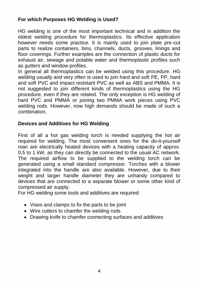
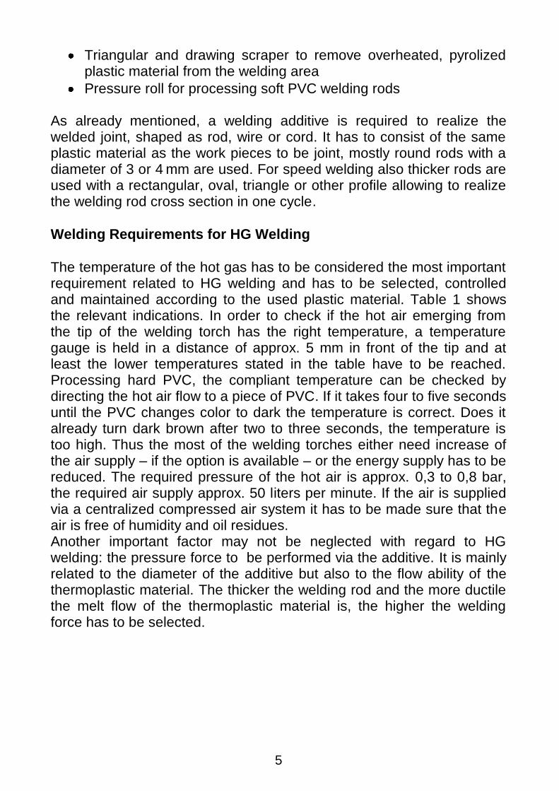
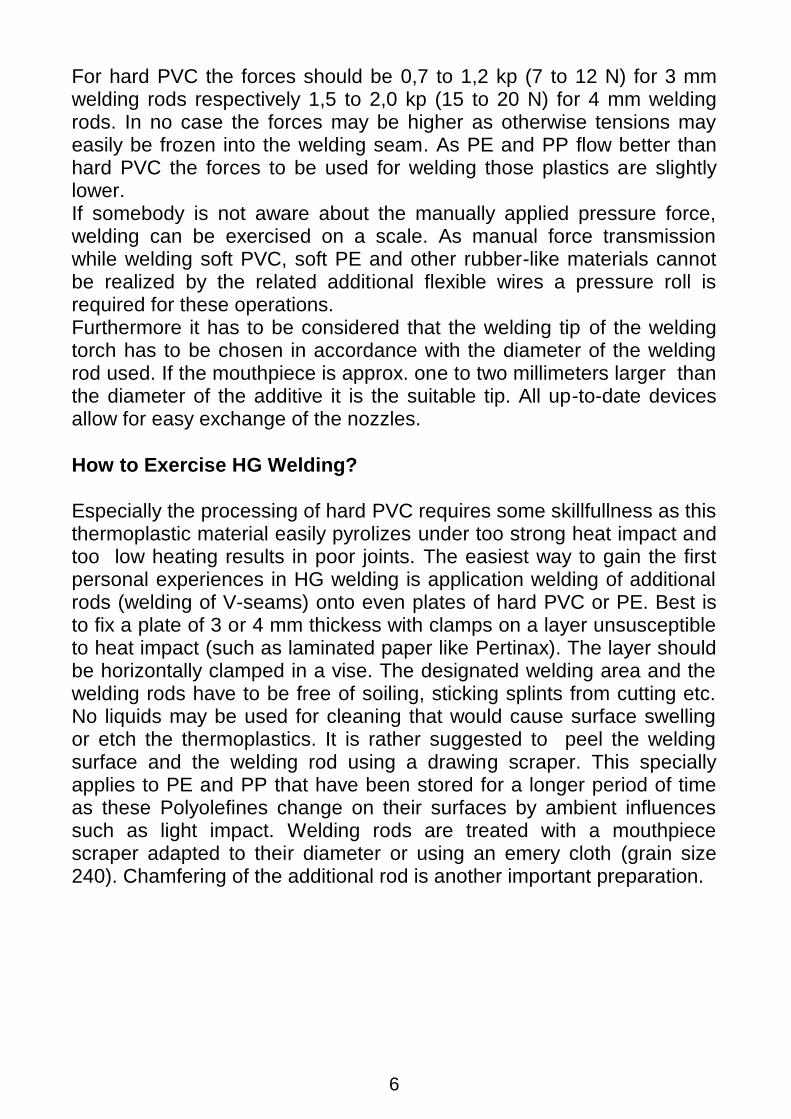
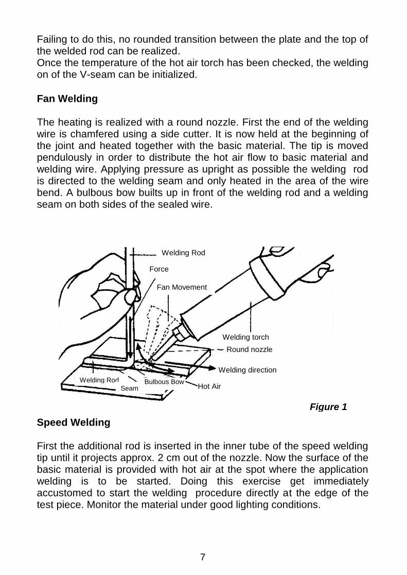
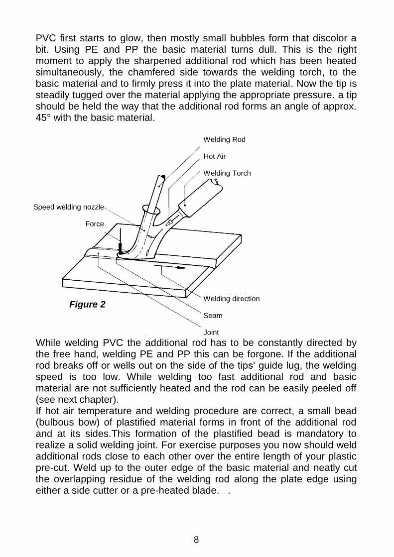
Fan Welding The heating is realized with a round nozzle. First the end of the welding wire is chamfered using a side cutter. It is now held at the beginning of the joint and heated together with the basic material. The tip is moved pendulously in order to distribute the hot air flow to basic material and welding wire. Applying pressure as upright as possible the welding rod is directed to the welding seam and only heated in the area of the wire bend. A bulbous bow builts up in front of the welding rod and a welding seam on both sides of the sealed wire.
Speed Welding First the additional rod is inserted in the inner tube of the speed welding tip until it projects approx. 2 cm out of the nozzle. Now the surface of the basic material is provided with hot air at the spot where the application welding is to be started. Doing this exercise get immediately accustomed to start the welding procedure directly at the edge of the test piece. Monitor the material under good lighting conditions.
Figure 1
Welding Rod
Force
Fan Movement
Welding torch
Round nozzle
Welding direction
Hot Air Welding Rod
Seam Bulbous Bow
8
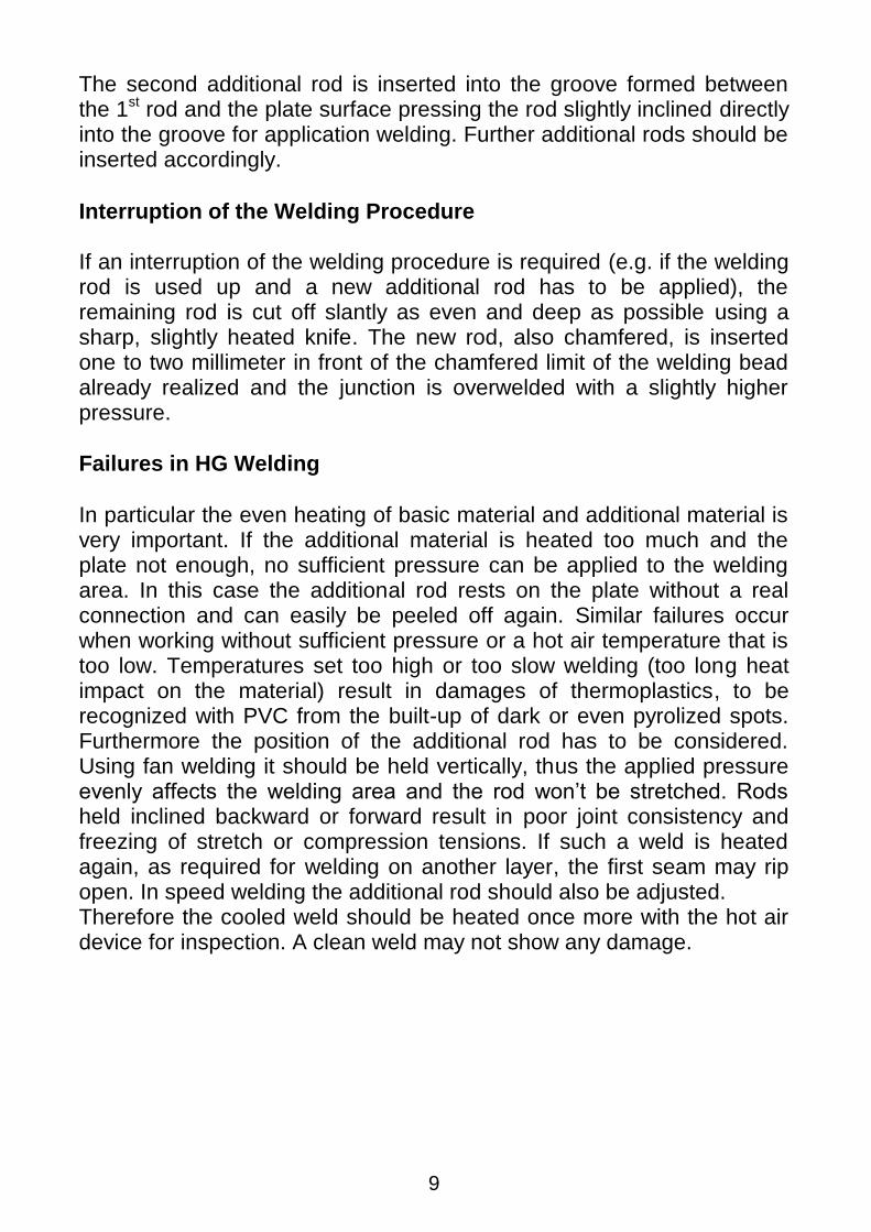
PVC first starts to glow, then mostly small bubbles form that discolor a bit. Using PE and PP the basic material turns dull. This is the right moment to apply the sharpened additional rod which has been heated simultaneously, the chamfered side towards the welding torch, to the basic material and to firmly press it into the plate material. Now the tip is steadily tugged over the material applying the appropriate pressure. a tip should be held the way that the additional rod forms an angle of approx. 45° with the basic material.
While welding PVC the additional rod has to be constantly directed by the free hand, welding PE and PP this can be forgone. If the additional rod breaks off or wells out on the side of the tips„ guide lug, the welding speed is too low. While welding too fast additional rod and basic material are not sufficiently heated and the rod can be easily peeled off (see next chapter). If hot air temperature and welding procedure are correct, a small bead (bulbous bow) of plastified material forms in front of the additional rod and at its sides.This formation of the plastified bead is mandatory to realize a solid welding joint. For exercise purposes you now should weld additional rods close to each other over the entire length of your plastic pre-cut. Weld up to the outer edge of the basic material and neatly cut the overlapping residue of the welding rod along the plate edge using either a side cutter or a pre-heated blade. .
Figure 2
Welding Rod Hot Air Welding Torch
Welding direction Seam Joint
Speed welding nozzle
Force
9
The second additional rod is inserted into the groove formed between the 1st rod and the plate surface pressing the rod slightly inclined directly into the groove for application welding. Further additional rods should be inserted accordingly.
Interruption of the Welding Procedure If an interruption of the welding procedure is required (e.g. if the welding rod is used up and a new additional rod has to be applied), the remaining rod is cut off slantly as even and deep as possible using a sharp, slightly heated knife. The new rod, also chamfered, is inserted one to two millimeter in front of the chamfered limit of the welding bead already realized and the junction is overwelded with a slightly higher pressure.
Failures in HG Welding
In particular the even heating of basic material and additional material is very important. If the additional material is heated too much and the plate not enough, no sufficient pressure can be applied to the welding area. In this case the additional rod rests on the plate without a real connection and can easily be peeled off again. Similar failures occur when working without sufficient pressure or a hot air temperature that is too low. Temperatures set too high or too slow welding (too long heat impact on the material) result in damages of thermoplastics, to be recognized with PVC from the built-up of dark or even pyrolized spots. Furthermore the position of the additional rod has to be considered. Using fan welding it should be held vertically, thus the applied pressure evenly affects the welding area and the rod won‟t be stretched. Rods held inclined backward or forward result in poor joint consistency and freezing of stretch or compression tensions. If such a weld is heated again, as required for welding on another layer, the first seam may rip open. In speed welding the additional rod should also be adjusted. Therefore the cooled weld should be heated once more with the hot air device for inspection. A clean weld may not show any damage.
Bild 2
10
Wrong positioning or guidance of the welding rod bears the risk of the material to be overstretched. Processing hard PVC stretches of more than 20% of the welding rod length are improper. The length check is the best way to check if such a failure has occurred. Mark, for instance, a section of 100 mm with pencil lines on the additional rod and use it to measure the length of the layer you welded with it. According to the example mentioned above you should have a maximum welding distance of 120 mm. Processing PE, PP and t PMMA the stretch of the additional rod should be below 10 %.
Preparation of Welding Areas and Joint Shapes Material thickness and load type are decisive for the selection of the joint shape. In general the joints used for HG welding are similar to those for metal welding.
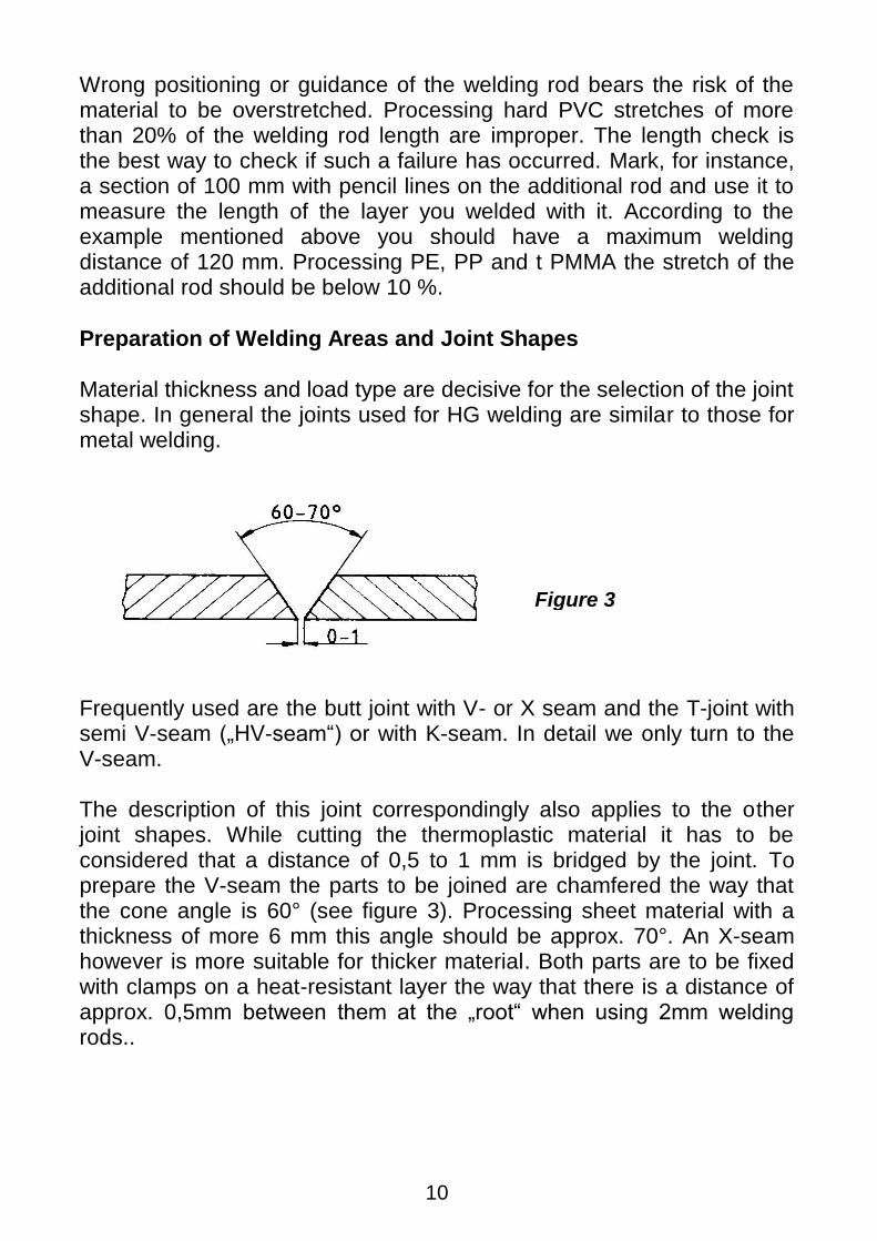
Frequently used are the butt joint with V- or X seam and the T-joint with semi V-seam („HV-seam“) or with K-seam. In detail we only turn to the V-seam. The description of this joint correspondingly also applies to the other joint shapes. While cutting the thermoplastic material it has to be considered that a distance of 0,5 to 1 mm is bridged by the joint. To prepare the V-seam the parts to be joined are chamfered the way that the cone angle is 60° (see figure 3). Processing sheet material with a thickness of more 6 mm this angle should be approx. 70°. An X-seam however is more suitable for thicker material. Both parts are to be fixed with clamps on a heat-resistant layer the way that there is a distance of approx. 0,5mm between them at the „root“ when using 2mm welding rods..
Figure 3
11
Using a 3mm welding rod to fill the root the distance is increased to approx. 1 mm.
Tacking In practice it is often difficult to maintain the work pieces to be welded in position with screw clamps or similar. Therefore it is common to fix the work pieces by tacking, thus preparing them for welding. First both parts are connected to each other at some spots with a special tacking nozzle without additional material (welding wire). The tacking nozzle, shaped like a pointed tube, is lead with slight pressure along the connection spot of both parts to make them melt into each other. If the final position of the parts to each other is realized, either the actual welding procedure can be initiated if the solidity allows for, or, the two parts are entirely tacked. If the tacking result is not satisfying the parts can easily be broken apart and tacked again. It has to be considered that a tacking seam never reaches the rigidity of a weld with additional material, it only serves to fix the individual work pieces. Work pieces where impermeability is crucial basically should be entirely tacked prior to the actual welding using a wire, as the tacking seam can easily be checked for cracks and joint failures. The temperature setting corresponds to the welding temperature of the material used. The welding speed is selected the way that both parts are joint without cracks on one hand, and no material is advanced by the nozzle on the other hand, as the tacking tip could easily be clogged and only little hot air escapes. Tacking should always be accompanied by the seam preparations described in the previous section.
Bild 3
12
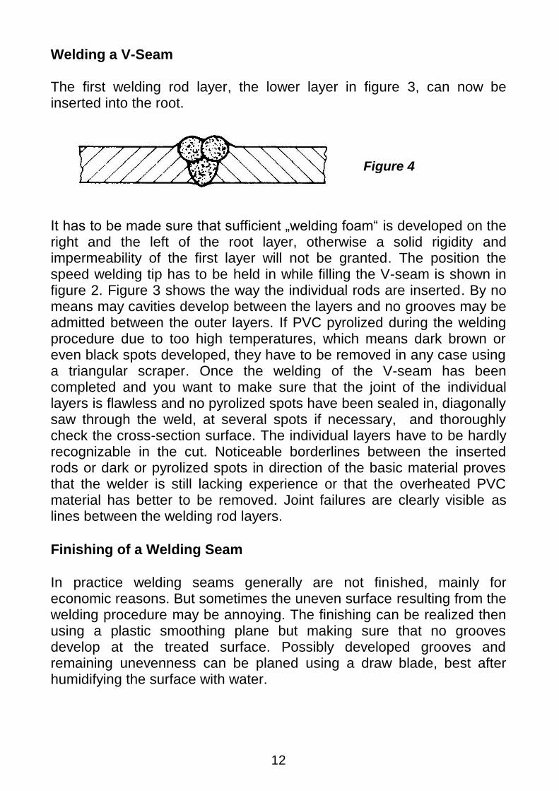
Welding a V-Seam The first welding rod layer, the lower layer in figure 3, can now be inserted into the root.
It has to be made sure that sufficient „welding foam“ is developed on the right and the left of the root layer, otherwise a solid rigidity and impermeability of the first layer will not be granted. The position the speed welding tip has to be held in while filling the V-seam is shown in figure 2. Figure 3 shows the way the individual rods are inserted. By no means may cavities develop between the layers and no grooves may be admitted between the outer layers. If PVC pyrolized during the welding procedure due to too high temperatures, which means dark brown or even black spots developed, they have to be removed in any case using a triangular scraper. Once the welding of the V-seam has been completed and you want to make sure that the joint of the individual layers is flawless and no pyrolized spots have been sealed in, diagonally saw through the weld, at several spots if necessary, and thoroughly check the cross-section surface. The individual layers have to be hardly recognizable in the cut. Noticeable borderlines between the inserted rods or dark or pyrolized spots in direction of the basic material proves that the welder is still lacking experience or that the overheated PVC material has better to be removed. Joint failures are clearly visible as lines between the welding rod layers.
Finishing of a Welding Seam
In practice welding seams generally are not finished, mainly for economic reasons. But sometimes the uneven surface resulting from the welding procedure may be annoying. The finishing can be realized then using a plastic smoothing plane but making sure that no grooves develop at the treated surface. Possibly developed grooves and remaining unevenness can be planed using a draw blade, best after humidifying the surface with water.
Figure 4
13
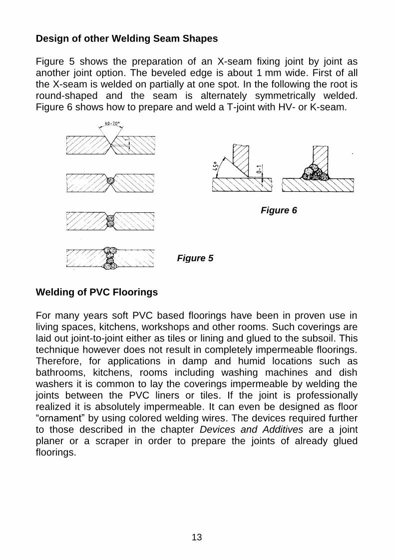
Design of other Welding Seam Shapes Figure 5 shows the preparation of an X-seam fixing joint by joint as another joint option. The beveled edge is about 1 mm wide. First of all the X-seam is welded on partially at one spot. In the following the root is round-shaped and the seam is alternately symmetrically welded. Figure 6 shows how to prepare and weld a T-joint with HV- or K-seam.
Welding of PVC Floorings
For many years soft PVC based floorings have been in proven use in living spaces, kitchens, workshops and other rooms. Such coverings are laid out joint-to-joint either as tiles or lining and glued to the subsoil. This technique however does not result in completely impermeable floorings. Therefore, for applications in damp and humid locations such as bathrooms, kitchens, rooms including washing machines and dish washers it is common to lay the coverings impermeable by welding the joints between the PVC liners or tiles. If the joint is professionally realized it is absolutely impermeable. It can even be designed as floor “ornament” by using colored welding wires. The devices required further to those described in the chapter Devices and Additives are a joint planer or a scraper in order to prepare the joints of already glued floorings.
Bild 4
Figure 5
Figure 6
14
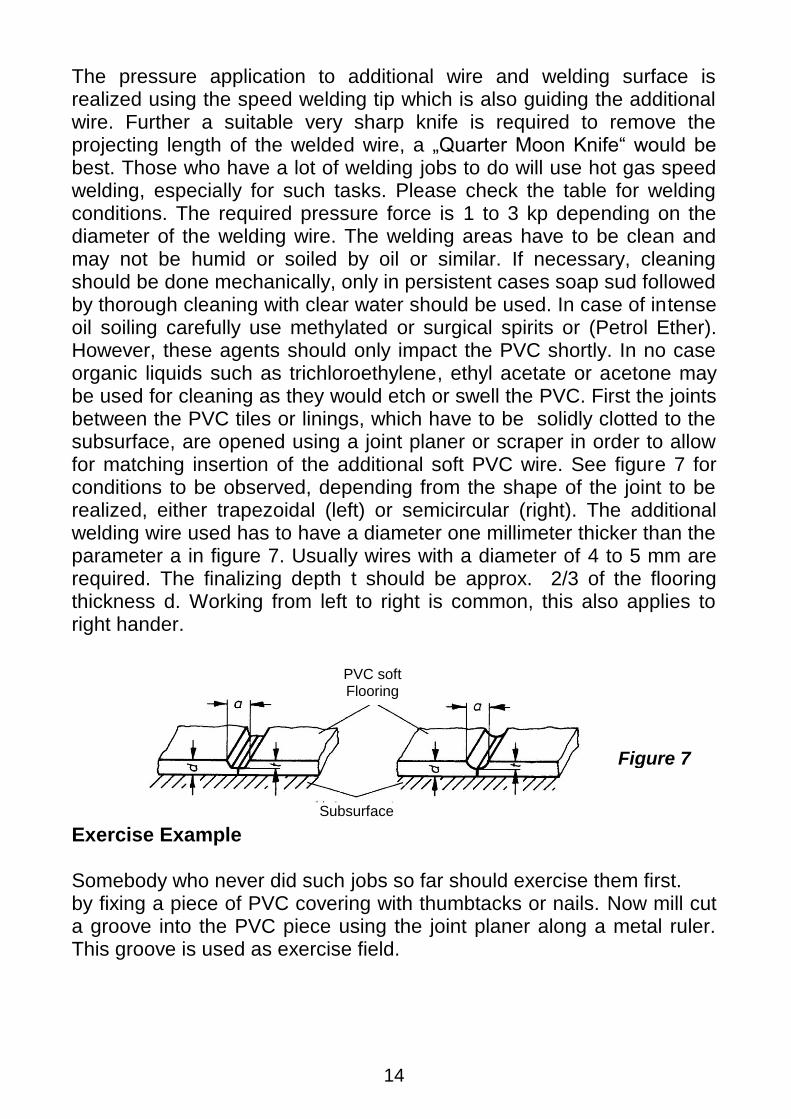
The pressure application to additional wire and welding surface is realized using the speed welding tip which is also guiding the additional wire. Further a suitable very sharp knife is required to remove the projecting length of the welded wire, a „Quarter Moon Knife“ would be best. Those who have a lot of welding jobs to do will use hot gas speed welding, especially for such tasks. Please check the table for welding conditions. The required pressure force is 1 to 3 kp depending on the diameter of the welding wire. The welding areas have to be clean and may not be humid or soiled by oil or similar. If necessary, cleaning should be done mechanically, only in persistent cases soap sud followed by thorough cleaning with clear water should be used. In case of intense oil soiling carefully use methylated or surgical spirits or (Petrol Ether). However, these agents should only impact the PVC shortly. In no case organic liquids such as trichloroethylene, ethyl acetate or acetone may be used for cleaning as they would etch or swell the PVC. First the joints between the PVC tiles or linings, which have to be solidly clotted to the subsurface, are opened using a joint planer or scraper in order to allow for matching insertion of the additional soft PVC wire. See figure 7 for conditions to be observed, depending from the shape of the joint to be realized, either trapezoidal (left) or semicircular (right). The additional welding wire used has to have a diameter one millimeter thicker than the parameter a in figure 7. Usually wires with a diameter of 4 to 5 mm are required. The finalizing depth t should be approx. 2/3 of the flooring thickness d. Working from left to right is common, this also applies to right hander.
Exercise Example Somebody who never did such jobs so far should exercise them first. by fixing a piece of PVC covering with thumbtacks or nails. Now mill cut a groove into the PVC piece using the joint planer along a metal ruler. This groove is used as exercise field.
Figure 7
PVC soft Flooring
Subsurface
15
Completion of the Welding Seam The part of the wire projecting the even surface of the PVC flooring (welding bead) is cut-off neatly and flushing with a sharp knife (quarter moon knife or similar tool).
Sheet Welding For welding of thermoplastic sheets (mostly PE or PVC) HG welding absolutely is the suitable alternative. For this purpose a special welding nozzle, the so-called wide slot nozzle is required. The air outlet mouthpiece is designed in a flat shape so it can be guided between two overlapping sheets. In addition a pressure roll made of rubber is required in order the apply the necessary welding pressure. Prior to welding the two sheet parts are prepared the way they overlap approx. 3 to 5 cm at their ends. Now the tip is guided tilted between the two parts with one hand, the other hand applies the welding pressure immediately behind the tip using the pressure roll. The temperature and pressure have been selected correctly (according to the HG temperature of the respective material) when a small bead builts-up at the edge of the upper sheet layer. In order to avoid sliding of the sheet while welding, it can be tacked at some spots using the wide slot nozzle prior to the welding procedure. It hast o be made sure that a proper joint is realized at these spots and all over the entire joint. The beginner should start with a couple of test welds in order to achieve the expertise required for this procedure. The exercise parts should be tested by a tearing-strength test after welding. Only when the result is satisfying the welding of a work piece should be initiated. The same procedure is applied for sheet repairs, e.g. pond linings. The patch, of course from the same material as the basic material, is cut in sufficient size and weight down in the middle in order to avoid sliding by the hot air flow at the beginning of the welding procedure.
Bild 7
16
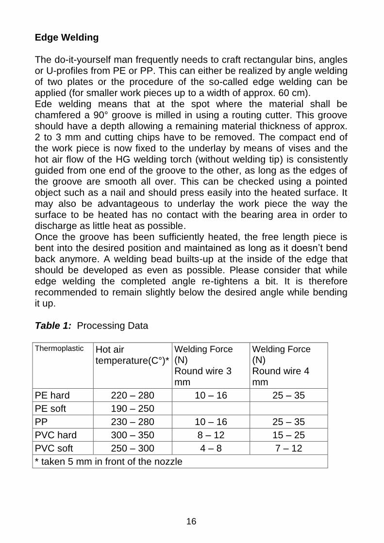
Edge Welding The do-it-yourself man frequently needs to craft rectangular bins, angles or U-profiles from PE or PP. This can either be realized by angle welding of two plates or the procedure of the so-called edge welding can be applied (for smaller work pieces up to a width of approx. 60 cm). Ede welding means that at the spot where the material shall be chamfered a 90° groove is milled in using a routing cutter. This groove should have a depth allowing a remaining material thickness of approx. 2 to 3 mm and cutting chips have to be removed. The compact end of the work piece is now fixed to the underlay by means of vises and the hot air flow of the HG welding torch (without welding tip) is consistently guided from one end of the groove to the other, as long as the edges of the groove are smooth all over. This can be checked using a pointed object such as a nail and should press easily into the heated surface. It may also be advantageous to underlay the work piece the way the surface to be heated has no contact with the bearing area in order to discharge as little heat as possible. Once the groove has been sufficiently heated, the free length piece is bent into the desired position and maintained as long as it doesn‟t bend back anymore. A welding bead builts-up at the inside of the edge that should be developed as even as possible. Please consider that while edge welding the completed angle re-tightens a bit. It is therefore recommended to remain slightly below the desired angle while bending it up. Table 1: Processing Data
Thermoplastic Hot air
temperature(C°)*
Welding Force (N) Round wire 3 mm
Welding Force (N) Round wire 4 mm
PE hard 220 – 280 10 – 16 25 – 35
PE soft 190 – 250
PP 230 – 280 10 – 16 25 – 35
PVC hard 300 – 350 8 – 12 15 – 25
PVC soft 250 – 300 4 – 8 7 – 12
* taken 5 mm in front of the nozzle
Wegener International GmbH Vaalser Str. 81 D-52074 Aachen [email protected]
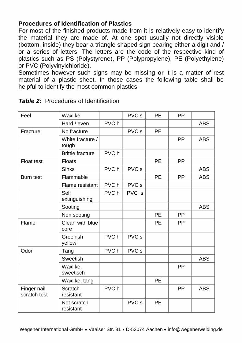
Procedures of Identification of Plastics For most of the finished products made from it is relatively easy to identify the material they are made of. At one spot usually not directly visible (bottom, inside) they bear a triangle shaped sign bearing either a digit and / or a series of letters. The letters are the code of the respective kind of plastics such as PS (Polystyrene), PP (Polypropylene), PE (Polyethylene) or PVC (Polyvinylchloride). Sometimes however such signs may be missing or it is a matter of rest material of a plastic sheet. In those cases the following table shall be helpful to identify the most common plastics.
Table 2: Procedures of Identification
Feel Waxlike PVC s PE PP
Hard / even PVC h ABS
Fracture No fracture PVC s PE
White fracture / tough
PP ABS
Brittle fracture PVC h
Float test Floats PE PP
Sinks PVC h PVC s ABS
Burn test Flammable PE PP ABS
Flame resistant PVC h PVC s
Self extinguishing
PVC h PVC s
Sooting ABS
Non sooting PE PP
Flame
Clear with blue core
PE PP
Greenish yellow
PVC h PVC s
Odor Tang PVC h PVC s
Sweetish ABS
Waxlike, sweetisch
PP
Waxlike, tang PE
Finger nail scratch test
Scratch resistant
PVC h PP ABS
Not scratch resistant
PVC s PE