Embed Size (px)
Citation preview


SCIENCIA ACTA XAVERIANA
An International Research Journal of Basic and Applied Sciences
SCIENCIA ACTA XAVERIANA (SAX) is a referred biannual
research Journal published in March and September by
St. Xavier’s College (Autonomous), Palayamkottai - 627 002.
SAX carries research articles from Basic and Applied Sciences
(Biology, Chemistry, Computer Science, Mathematics, and Physics).
PATRONS
Rev. Dr. Danis Ponniah, S.J., Rector
Rev. Fr. Jesu Michael Das, S.J., Secretary
Dr. V. Gilburt Camillus S.J., Principal
St. Xavier’s College, Palayamkottai, India.
EDITORIAL BOARD
Editor- in-Chief
Dr. A. Lourdusamy,
Department of Mathematics, St.Xavier’s College, Palayamkottai, India.
[email protected], [email protected]
MEMBERS
Dr. Anton Ilango Department of Systems Physiology of Learning
Leibniz Institute for Neurobiology, Breeneckestraβe6,
39118, Magdeburg, Germany.
Email : [email protected]
Dr. O. N. Oigiangbe Department of Zoology, Ambrose Alli University, Nigeria.
Email : osawe_oigangbe @ hotmail.com
Dr. Antony Jeevarajan Deputy Division Chief,
Habitability and Environmental Factors Division,
Johnson Space Centre, NASA, USA.
Email : [email protected].
Dr. M. Venkatesan The University of Dublin, Trinity College,
Dublin, Ireland.
E-mail : [email protected]
Dr. Amsarani Ramamoorthy Textile Engineering, Chemistry and Science,
North Carolina State University, USA.
E-mail : [email protected]
Dr. M. Amsaveni Bhabha Atomic Research Centre
Trombay, Mumbai.
Email : [email protected]

Dr. Raja Angamuthu Department of Chemistry,
Indian Institute of Technology, Kanpur,
Uttarpradesh 208 016.
Email : [email protected]
Dr. S. Meheshwaran Indian Institute of Technology,
Powai, Mumbai.
Email : [email protected]
Dr. G. Raja Raman Department of Chemistry,
Indian Institute of Technology, Bombay.
Email : [email protected]
Dr. Satheesh Krishnamurthy Nanoscale Energy and Surface Engineering Group
The Open University, UK.
Email : [email protected]
Dr. R.Lakshminarayanan Senior Manager (Scientist E3), R & D Center
HLL Lifecare Limited (a Government of India Enterprise),
Akkulam, Sreekaryam (PO), Trivandrum - 695017, India.
Email : [email protected]
Dr. Sukumar Venkataramani Indian Institute of Science Education and Research
(IISER) - Mohali, Knowledge City, Sector 81,
SAS Nagar, Manauti, Punjabi - 140306,
Email : [email protected]
Dr. E.M. Mothi Centre for Scientific and Applied Research,
PSN College of Engineering and Technology,
Tirunelveli - 627 152, India.
Email : [email protected]
Dr. M. Sankar Cardiff Catalysis Institute
Cardiff University,
Cardiff CF103AT, UK.
E-mail : [email protected]
Dr. Enrico Marsili School of Biotechnology
Dublin City University,
Glasnevin, Dublin 9, Ireland,
E-mail : [email protected]
MEMBERS FROM ST.XAVIER’S COLLEGE
Dr. L. Henry Joseph Department of Botany
E-mail : [email protected]
Dr. A. John De Britto Department of Botany
E-mail : [email protected]
Dr. K. Sahayaraj Department of Zoology
E-mail : [email protected]
Dr. V. Jeyapaul Department of Chemistry
E-mail : [email protected]
Dr. M. Baby Maryatra Department of Chemistry
E-mail : [email protected]
Dr. S.P. Victor Department of Computer Science
E-mail : spvictor [email protected]
Dr. S. Athisayanathan Department of Mathematics
E-mail : [email protected]
Rev. Dr. A. Arockiasamy, S.J. Department of Mathematics
E-mail : [email protected]
Rev. Dr. Danis Ponniah, S.J. Department of Physics
E-mail : [email protected]
Dr. D. Prem Anand Department of Physics
E-mail : [email protected]
Subscription Rates
ANNUAL SUBSCRIPTION
(i) for individuals : Rs 300 (in India) US $50 (airmail)
(ii) for institutions: Rs 2000 (in India) US $ 100 (air mail)
Subscription orders along with a Demand Draft drawn in favour of “Sciencia Acta Xaveriana”
payable at Tirunelveli, may please be sent to the Editor-in-chief.
Disclaimer : Opinions expressed are those of their authors and not the responsibility of the
Board, the Editors or the publisher. All disputes arising, if any, are subjected to the exclusive
jurisdiction of competent court in Palayamkottai, Tamilnadu, India.
INFORMATION FOR AUTHORS
SCIENCIA ACTA XAVIERIANA - An International Research Journal of Basic and Applied
Sciences aims at publication of original research papers, comprehensive review articles, book-
reviews, dissertation abstracts etc. devoted to any area in science (Biology, Chemistry,
Computer Science, Mathematics, and Physics).

Manuscripts must be submitted electronically to the Editor-in-Chief through :
[email protected], [email protected]. Authors may submit manuscripts to any
member of the Editorial Board. No hard copy should be sent.
Submitted manuscripts must not have been published nor be under consideration for publication
elsewhere. Publication of paper in the journal automatically transfers the copyrights from the
authors to the publisher.
All manuscripts should be sent electronically in either .pdf or.doc format, type set in English
with double spacing. The file must be prepared using preferably by La-TeX processing system
or MS word. The paper should contain the following headings:
1. Title 8. Results/observations
2. Author/Authors 9. Discussion
3. Institution with address and E-mail 10. References
4. Summary with not more than 250 words 11. Appendix (if any)
5. Keywords – Maximum ten 12. Tables
6. Introduction 13. Figures - Illustrations or photos
7. Materials and Methods (B/W or colour, JPEG or
Photoshop files of all
photographs)
References : Citations within the text are given within square brackets like [5], [9, 11],
[22-25] etc. The List of references shall be given at the end of the manuscript in alphabetical
order :
[1] G. Chartrand and P. Zang, Distance in Graphs – Taking the long view, AKCE.J. Graphs,
1 No. 1 (2004), 1-13.
[2] M. Johnson, J. Vallinayagam, V.S. Manickam and S. Seeni, Multiplication of rhinacanthus
nasutus through micro propagation, Phytomorphology, 52, No.4 (2002), 331-336.
[3] M. Nielsen and I. Chuang, Quantum Computation and Quantum Information, Cambridge
University Press, 2000.
All manuscripts are subjected to anonymous review by two independent reviewers. The editorial
board will make the decision within two months after submission.
Once a paper has been accepted, send a .pdf or .doc file as well as the LATEX file to the
Editor-in-Chief. The file must be in 11 point Times or Computer modern font, 1.5 spaced,
with the text being 5.75 x 8.25 inches (14.60 x 20.96cm). On the first page leave 1 inch space
on the top for the journal’s headings.

1
Sciencia Acta Xaveriana Volume 6 An International Science Journal No. 2
ISSN. 0976-1152 pp. 1-48
September 2015
Introduction to Molecule based Nano magnetic Materials
Tulika Gupta
Dept. of Chemistry, IIT Bombay, Mumbai-400076
Abstract: “Molecular Magnets are single molecules consisting of a magnetic core and shielding
organic ligands. “Molecular Magnets with versatile dimensionality, whether they are zero-
dimensional single-molecule magnets (SMMs) or one-dimensional single-chain magnets (SCMs) have
wide potential applications as they permit investigation of the fundamental aspects lying at the
interphase of quantum and classical physics at the nanoscale level. This area has been such
extensively explored in the quest of procuring a solid being magnetically ordered at long distance
without interaction between molecules. This is viable due to the concomitant anisotropic barrier,
which resulted in proper alignment of molecule in a given direction and is of purely molecular origin.
Once directed in a direction, the magnetization of the molecular solid relaxes very slowly either by
thermal action, above the barrier, or by “tunnelling effect” through the anisotropic barrier. This is
another of the wonders of quantum mechanics, to be able to cross obstacles without having to jump
them. They have magnetic anisotropy and show ferromagnetic behavior when cooled sufficiently.
This makes them interesting not only for data storage purpose but also for observing quantum effects
in mesoscopic objects. The ferromagnetic behavior is due to the high spin ground state and its (2S+1)
secondary spin states. Because of the negative Zero Field Splitting an energy barrier is created that
causes the magnetization to relax slowly over time because the thermal inversion of the magnetic
moment is phonon induced with steps of ∆MS= -1 or ∆MS= -2. Additionally Quantum Tunneling of
Magnetization, appearing at degenerate states, enhances the relaxation process. The contribution of
this phenomenon increases with increasing temperature. SMMs open a new way towards high density
magnetic information storage; it indeed becomes possible to dream of anisotropic molecular systems
with high spin, assembled from the bottom or “bottom up” from small molecular precursors,on which
it would be possible to store information on a single molecule.The challenge is formidable but gives a
remarkable field for synthetic chemists, quantum physicists and engineers to work together in

Tulika Gupta 2
synergy. To finally use Molecular Magnets as Bits in a binary System an implementation to a medium
is required. In this talk the implementation to Carbon Nanotubes is addressed.”
Motivation and Basic Knowledge: The idea of storing information using the
ferromagnetic property of a remanent field goes back to 1898 where Valdemar Poulsen, a Danish
Engineer, invented the Telegraphon. This device was capable of storing a magnetic amplitude
which was proportional to the recorded signal on a moving wire. The principle had not
changed when Fritz Pfleumer, a German-Austrian engineer, upgraded the recording medium to
a tape which carried a powder of iron oxide. The obvious benefit of the new medium was
the low weight and the increased capacity. He granted his idea to the German company AEG
which built the worlds first tape recorder named Magnetophon K1. A real revolution had taken place
when IBM 1956 invented the first magnetic hard drive, the IBM 305, which could store the
amount of 5 MB of data with a density of 2000 b/in2. In the following years improvements
have been made to increase the density of hard drives exponentially (doubling every two years) to
the current value of 300 Gb/in2. This increase will find its limit because of the superparamagnetic
limit. This phenomenon refers to thermally induced spin flipping at sufficiently low temperatures.
Acknowledgement: This review is written partly based on Diamond Jubilee celebration
lecture at the department Chemistry, St. Xavier's College, Tirunelveli, Tamilnadu by Prof. Gopalan
Rajaraman, Department of Chemistry, IIT Bombay and also based on his lecture notes on Advances
in Molecular magnetism at the department of Chemistry, IIT Bombay. We would like to express our
gratitude to all the eminent scientists across the world working in the area of molecular magnetism
since past two decades, i.e. Prof. O. Kahn, Prof. D.Gatteschi, Prof. R. Sessoli, Prof. A. Caneschi, Prof.
A.K.Powell, Prof. J. Long, Dr. J. V. Slageren, Prof. M. Murugesu, Prof. R.E.P.Winpenny, Prof. L.
Chibotaru, Prof. J. Tang, Dr. L. Ungur, Prof. W. Wernsdorfer, Prof. G. Christou, Prof. E. K. Brechin,
Prof. L .Jones, Prof. E. Coronado, Prof. E. Colacio, Prof. E. Ruiz, Prof. K. S. Murray, Prof. N.
Ishikawa, Prof. Helene Bolvin, Prof. E. J. McInnes, Prof. D. Collison, Prof. R. Clerac, Prof. C.
Coulon, Prof. A. Bencini, Prof. L. Bogani, Prof. S. Piligkos, Prof. M. Evangilisti, Prof. M. Affronte,
Prof. G. Aromin, Prof. K. Bernot, Prof. V. Chandrasekhar, Prof. A. Duncan, Prof. F. Neese, Prof. H.
Miyasaka, Dr. S. Langley,J. Friedman, Prof. K. Dietrich and Prof. S. Maheswaran. Most importantly,
we are indebted to Prof. M. Verdaguer whose lectures on molecular magnetism have been used for
our summarised write-up on molecular magnetism. We have also taken suggestions from books
written by Prof. O. Kahn, Prof. E. J. Miller and M. Drillon, Prof. E. K. Itoh and M. Kinoshita, Prof.
M. Verdaguer and Prof. E. Linrt proved to be extremely beneficial for our summary. We have
performed thorough study on all of their published materials on molecular magnets and procured
ideas have been used to write this journal and perform calculations for our research project.
Eventually, GR would like to acknowledge financial support from the Government of India through

3 Molecular Nanomagnets
the Department of Science and Technology (SR/NM/NS-1119/2011) and Indian Institute of
Technology, Bombay to access the high performance computing facility. TG would like to thank
UGC New Delhi for SRF fellowship.

Tulika Gupta 4
Figure 1.Magnetization vs magnetic field plot for
different kind of magnetic species
§1. Molecule based magnets and Molecular NanoMagnets:
We consider an assembly of magnetic molecules interacting ferromagnetically, and we assume that
these molecules are all of the same type. At temperatures much higher than Tc intermolecular
interactions do not influence the magnetic properties. If each molecule contains a unique magnetic
center, then the magnetic susceptibility χ varies according to the Curie law, provided that there is no
first-order orbital momentum. If each molecule contains several magnetic centers, the intramolecular
interactions generally predominate. These may be either FM or AFM, but, in this latter case, they
must lead to a nondiamagnetic ground state. Such a situation is achieved, for instance, for an odd
number of equivalent local spins, or for a pair of nonequivalent local spins. If we ignore
intermolecular interactions for a moment, then the molar magnetic susceptibility χ should follow the
Curie law in the temperature range where only the molecular ground state is thermally populated, with
the Curie constant depending on the ground state spin. Actually, we assume that significant
intermolecular ferromagnetic effects are operative. If this is so, as T decreases and approaches Tc, χ
increases faster than anticipated for the Curie law, which is easily detected when plotting χT versus T.
χT increases more and more rapidly on cooling. This enhancement in χT is related to an increase in the
correlation length. At temperatures not too close to Tc the intermolecular interactions can be fairly
well accounted for by the mean-field approximation. At Tc, χ and χT should in principle diverge, and a
spontaneous magnetization should appear. On cooling further, the magnetization increases to a
saturation value Ms = NβgS, where S is the spin associated with the molecular ground state and g is
the Zeeman factor.
Practically at zero magnetic field, no
magnetization is usually detected. This is governed by two
factors, domain formation and demagnetizing field. A
sample of a ferromagnetic material is generally broken into
domains. Each domain has a net magnetization in zero
field, directed in a given direction. The magnetic moments
of the domains are randomly oriented within the sample
such that the resulting magnetization is zero. An external
magnetic field provokes a displacement of the
domain walls and the formation of a new
domain structure. The magnetic moments of
the domains are no longer randomly oriented but tend to align along the field. A magnetization M is
then observed. If the sample was a monodomain, the M = f{H) variation at T≤ Tc would be as shown
in below figure with an infinite zero-field susceptibility (dM/dH)H=0. Since domain formation is taking
place, the slope of the M versus H plot for H = 0 is very large but not infinite. We need to emphasise
that increase of M vs H is much faster for a ferromagnetic material than for a paramagnetic system.
00
real magnet
paramagnetic species
Mag
neti
zati
on
Magnetic Field
ideal magnetM
S
5 Molecular Nanomagnets
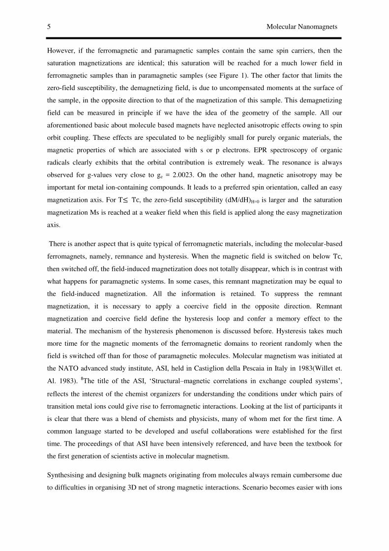
However, if the ferromagnetic and paramagnetic samples contain the same spin carriers, then the
saturation magnetizations are identical; this saturation will be reached for a much lower field in
ferromagnetic samples than in paramagnetic samples (see Figure 1). The other factor that limits the
zero-field susceptibility, the demagnetizing field, is due to uncompensated moments at the surface of
the sample, in the opposite direction to that of the magnetization of this sample. This demagnetizing
field can be measured in principle if we have the idea of the geometry of the sample. All our
aforementioned basic about molecule based magnets have neglected anisotropic effects owing to spin
orbit coupling. These effects are speculated to be negligibly small for purely organic materials, the
magnetic properties of which are associated with s or p electrons. EPR spectroscopy of organic
radicals clearly exhibits that the orbital contribution is extremely weak. The resonance is always
observed for g-values very close to ge = 2.0023. On the other hand, magnetic anisotropy may be
important for metal ion-containing compounds. It leads to a preferred spin orientation, called an easy
magnetization axis. For T≤ Tc, the zero-field susceptibility (dM/dH)H=0 is larger and the saturation
magnetization Ms is reached at a weaker field when this field is applied along the easy magnetization
axis.
There is another aspect that is quite typical of ferromagnetic materials, including the molecular-based
ferromagnets, namely, remnance and hysteresis. When the magnetic field is switched on below Tc,
then switched off, the field-induced magnetization does not totally disappear, which is in contrast with
what happens for paramagnetic systems. In some cases, this remnant magnetization may be equal to
the field-induced magnetization. All the information is retained. To suppress the remnant
magnetization, it is necessary to apply a coercive field in the opposite direction. Remnant
magnetization and coercive field define the hysteresis loop and confer a memory effect to the
material. The mechanism of the hysteresis phenomenon is discussed before. Hysteresis takes much
more time for the magnetic moments of the ferromagnetic domains to reorient randomly when the
field is switched off than for those of paramagnetic molecules. Molecular magnetism was initiated at
the NATO advanced study institute, ASI, held in Castiglion della Pescaia in Italy in 1983(Willet et.
Al. 1983). 8The title of the ASI, ‘Structural–magnetic correlations in exchange coupled systems’,
reflects the interest of the chemist organizers for understanding the conditions under which pairs of
transition metal ions could give rise to ferromagnetic interactions. Looking at the list of participants it
is clear that there was a blend of chemists and physicists, many of whom met for the first time. A
common language started to be developed and useful collaborations were established for the first
time. The proceedings of that ASI have been intensively referenced, and have been the textbook for
the first generation of scientists active in molecular magnetism.
Synthesising and designing bulk magnets originating from molecules always remain cumbersome due
to difficulties in organising 3D net of strong magnetic interactions. Scenario becomes easier with ions

Tulika Gupta 6
or metals, where the building block are spherical, while reality remains always far with the building
blocks, being of low symmetry. This enables the easy procurement of comparatively large number of
low-dimensional materials using molecular building blocks.
However, this difficulty may turn out to be an advantage if the target is changed from three-
dimensional magnets to low-dimensional and, in particular, zero-dimensional magnets. Indeed the
interest in finite-size magnetic particles had developed in the 1980s as a consequence of the growing
interest in the so-called nanoscience. It was realized that nanosize objects can be particularly
interesting because matter organized on this scale has enough complexity to give rise to new types of
properties, and yet it is not too complex and can be investigated in depth in much detail. The interest
in nanoscience (and, in perspective, for nanotechnology) spans all the traditional disciplines.
conductors and semiconductors, as a result of the impetus on the miniaturization processes associated
with more efficient computers. One of the challenges is the realization of objects of size so small that
they gave rise to the coexistence of classical and quantum properties. The most interesting results
were in the field of quantum dots and quantum wires , 9, 10 which correspond to objects whose size is
in the nanometre range in three or two directions, respectively. Progress was made possible by the
development of experimental techniques, which allowed ‘seeing’ and investigating the properties of
particles of a few nanometres. Among them a particular relevant place was kept by scanning probe
microscopy techniques, like atomic force microscopy, scanning tunnel microscopy, etc.
Magnetism could not be an exception, and one of the relevant themes was the possibility of observing
quantum tunnelling effects in mesoscopic matter. A scheme, showing the size effects in the
magnetization dynamics and hysteresis loop going from multidomain magnetic particles to molecular
clusters has been given below as suggested by Sir Wernsdorfer in 2001.
Figure 2. The above figure shows transition from macroscopic to nanoscopic magnets. The hysteresis
loops are typical example of magnetization reversal via nucleation, propagation, annihilation of
domain walls (left), via uniform rotation (middle) and quantum tunnelling (right). 11

7 Molecular Nanomagnets
Figure 3. Plot of energy of an Ising (easy axis) type
magnet as a function of the angle of the
magnetization from easy axis.
At the macroscopic limit the particles contain at least billions of individual spins, which are coupled
in such a way that the individual moments will respond all together to external stimuli. The magnetic
energy is minimized by forming domains, regions in space within which all the individual moments
are parallel (antiparallel) to each other. The orientation of the moments of the domains will be random
in such a way that in the absence of an external magnetic field the magnetization of the sample is
zero. The transition from a domain to the neighbouring one will occur through a region where the
local magnetic moments are rapidly varying, called the Bloch walls. The width of the Bloch walls, d,
depends on the exchange coupling constant J, which tens to keep the spins ordered and to make the
walls as large as possible, in order to minimize the effort needed to change the orientation of the
moments, and on the magnetic anisotropy, which tends to minimize the Bloch walls to reduce the
probability of high-energy orientations. Obviously the width of the domain walls depends on the
nature of the magnetic material.
When the sample is magnetized all the individual moments will
eventually be parallel to each other and the magnetization reaches its
saturation value. If the field is decreased the formation of domains
will not be reversible in such a way that the magnetization at zero field
will not be zero, like in the non-magnetized case. The finite value of
the magnetization in zero field is called the remnant magnetization. In
order to demagnetize the sample it is necessary
to go to a negative field, which is called the
coercitive field. This value is used in order to
classify the bulk magnets: a small value of the
coercitive field is typical of soft magnets, while in hard magnets the coercitive field is large. The M/H
plot, shown in above figure on the left, shows a hysteresis loop, which tells us that the value of the
magnetization of the sample depends on its history. This is the basis of the use of magnets for storing
information.
On reducing the size of the magnetic particles a limit is reached when the radius of the particle is
small compared to the Bloch wall depth. Energetically the process of domain wall formation is no
longer economical and the particle goes single domain.
By further reducing the size of the particles, another effect is further invoked. The magnetic
anisotropy of the sample, A, depends on the size of the particle: � = ��
En
erg
y
-π/2 +π/2
0
θ
Tulika Gupta 8
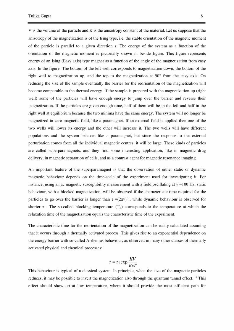
V is the volume of the particle and K is the anisotropy constant of the material. Let us suppose that the
anisotropy of the magnetization is of the Ising type, i.e. the stable orientation of the magnetic moment
of the particle is parallel to a given direction z. The energy of the system as a function of the
orientation of the magnetic moment is pictorially shown in beside figure. This figure represents
energy of an Ising (Easy axis) type magnet as a function of the angle of the magnetization from easy
axis. In the figure The bottom of the left well corresponds to magnetization down, the bottom of the
right well to magnetization up, and the top to the magnetization at 90° from the easy axis. On
reducing the size of the sample eventually the barrier for the reorientation of the magnetization will
become comparable to the thermal energy. If the sample is prepared with the magnetization up (right
well) some of the particles will have enough energy to jump over the barrier and reverse their
magnetization. If the particles are given enough time, half of them will be in the left and half in the
right well at equilibrium because the two minima have the same energy. The system will no longer be
magnetized in zero magnetic field, like a paramagnet. If an external field is applied then one of the
two wells will lower its energy and the other will increase it. The two wells will have different
populations and the system behaves like a paramagnet, but since the response to the external
perturbation comes from all the individual magnetic centres, it will be large. These kinds of particles
are called superparamagnets, and they find some interesting application, like in magnetic drug
delivery, in magnetic separation of cells, and as a contrast agent for magnetic resonance imaging.
An important feature of the superparamagnet is that the observation of either static or dynamic
magnetic behaviour depends on the time-scale of the experiment used for investigating it. For
instance, using an ac magnetic susceptibility measurement with a field oscillating at =100 Hz, static
behaviour, with a blocked magnetization, will be observed if the characteristic time required for the
particles to go over the barrier is longer than τ =(2π )−1, while dynamic behaviour is observed for
shorter τ . The so-called blocking temperature (TB) corresponds to the temperature at which the
relaxation time of the magnetization equals the characteristic time of the experiment.
The characteristic time for the reorientation of the magnetization can be easily calculated assuming
that it occurs through a thermally activated process. This gives rise to an exponential dependence on
the energy barrier with so-called Arrhenius behaviour, as observed in many other classes of thermally
activated physical and chemical processes:
This behaviour is typical of a classical system. In principle, when the size of the magnetic particles
reduces, it may be possible to invert the magnetization also through the quantum tunnel effect. 12 This
effect should show up at low temperature, where it should provide the most efficient path for
0 expB
KV
K T

9 Molecular Nanomagnets
magnetic relaxation only if the wavefunctions of the left and of the right well have some overlap. The
quest for exploring quantum effects in magnetic nanoparticles will be investigated in detail.
The size of the particles needed to observe superparamagnetic behaviour ranges from 2–
3 to 20–30 nm, depending on the nature of the material. Magnetic nanoparticles are obtained in many
different ways, ranging from mechanical grinding to sol–gel techniques. An original procedure uses
naturally occurring materials like ferritin, the ubiquitous iron storage protein. Iron is needed in the
metabolism of living organisms, and it must be stored in some place in order to use when it is needed.
Nature chose ferritin to do this job in animals, plants, fungi, and bacteria. Man has an average of 3–4
g iron and ca. 30 mg per day are exchanged in plasma. Structurally ferritin comprises a proteic shell,
apoferritin, and a mineral core, of approximate composition FeOOH. The size of the internal core is
ca. 7 nm, giving rise to superparamagnetic behaviour in the iron oxide particles, which can contain up
to ca. 4000 metal ions.
Definite improvements have been made recently in the techniques to obtain monodisperse assemblies
of magnetic particles. In some cases it has been possible to obtain identical particles that have been
‘crystallized’.In fact if spherical particles all identical to each other are put together they will try to
occupy space in the most efficient way, giving rise to a close packed array exactly as atoms do in
crystals.
An alternative to using magnetic nanoparticles, i.e. of reducing the size of bulk magnets in a sort of
top-down approach, is that of using a molecular approach in a bottom-up approach. 13 The idea is that
of synthesizing molecules containing an increasing number of magnetic centres. In the ideal process
one would like to be able to add one magnetic centre at a time, starting from one and going up to say a
few thousand magnetic centres. The theoretical advantage of the molecular approach is that molecules
are all identical to each other, therefore allowing the performance of relatively easy experiments on
large assemblies of identical particles, and still being able to monitor elusive quantum effects.
Molecules can be easily organized into single crystals, therefore allowing the performance of accurate
measurements. Further, they can be investigated in solutions, thus destroying all the intermolecular
magnetic interactions that might give rise to spurious effects. As an alternative to single crystals it is
possible to organize them in self-assembled monolayers and address them with microscopic
techniques like STM. Therefore molecular nanomagnets have great promise and they well deserve the
effort needed to design and synthesize them.
The idea of making molecules of increasing size by adding the magnetic centres one at a time is
certainly appealing, but unfortunately it is not like that that chemistry goes. However, some successful
strategies have led to noticeable results such as the spectacular increase in the size of manganese
molecular clusters achieved by Christou and co-workers and schematized in following figure 4:

Tulika Gupta 10
Hence, magnetic molecular clusters which are known as molecular nanomagnets have received this
classification due to their presence at the final point in the series of smaller and smaller units from
bulk matter to atoms. To date they have been the most promising candidates for observing quantum
Figure 4. Increasing size and nuclearity of molecular clusters containing manganese ions that
approach the size of nanosized magnetic particles. 14, 15
phenomena as they have a well defined structure with well characterized spin ground state and
magnetic anisotropy. Moreover, they can be regularly assembled in large crystals where all molecules
often have the same orientation. Therefore, macroscopic measurements can give direct access to
single molecule properties.Hence, molecular nanomagnets can be referred to as large (Avogadro’s )
number of magnetic molecules which are nearly identical, providing ideal laboratories for the study of
nanoscale magnetic phenomena. Hence, Molecular nanomagnets have been undergoing dev
elopment for 20 years since the first single-molecule magnet (SMM), Mn12Ac, 16 was characterized
as the molecule-behaved magnet. The multi-disciplinary scientists promoted the magnetic
characteristics to be more suitable for use in information science and spintronics. 17 The
concept of molecular nanomagnets has also evolved to include single-chain magnets (SCMs),
single-ion magnets (SIMs) and even magnetic molecules that showed only slow magnetic relaxation,
in addition to the initial cluster-type SMMs. The discovery and subsequent development of
molecular nanomagnets (single-molecule magnets, SMMs; single- chain magnets, SCMs; single-
ion magnets, SIMs) have led to a fascinating intermediate regime between the realm of
paramagnetism and bulk magnetism. Below the so-called blocking temperature TB, the
magnetization reversal of a molecular nanomagnet is efficiently blocked owing to an effective energy

11 Molecular Nanomagnets
barrier Ueff, and magnetic hysteresis of purely molecular origin can be observed. Furthermore,
quantum properties, such as quantum tunnelling of the magnetization and quantum interference,
were observed in these systems, leading to the potential applications of molecular nanomagnets
in molecule spintronics, spin valves, transistors and the future generation of information
storage and quantum computing.
§1.1. Representative examples of Single Molecule Magnets (SMMs) and
mononuclear SMMs or Single Ion Magnets (SIMs):
§16.1.1.Characteristics:
Hence, single molecule magnets (SMMs) could retain magnetisation in the absence of a magnetic
field. They Represent the smallest possible magnetic storage device, retaining information in a single
molecule rather than in a magnetic particle or an array of particles. SMMs undergo quantum
tunnelling and are possible q-bits in quantum computers. “A single molecule that behaves as a
nanoscale magnet below a critical temperature. i.e. displays hysteresis of molecular origin”.
Figure 5. Pictorial representation of the orientation of electronic spins of a single molecule magnet.
Hence, a SMM can be regarded as a molecule which exhibits slow relaxation of magnetization of
purely molecular origin. It is molecule which will be magnetized in presence of magnetic field and
even will retain its magnetization on removal of the field. This feature is solely molecular
characteristics and no intermolecular interactions are needed to spur such phenomenon. This
differentiates SMMs from its traditional bulk magnet congeners. On dissolving a SMM in a solvent or
placing into some matrix (i.e. polymer) we will be able to detect SMM property. SMMs are basically
general class of complexes i.e. exchange coupled clusters. Most often, SMMs are parts of a mineral
lattice encapsulated by the organic ligands. In materials sciences, one molecule of SMM can be
considered as one bit which led to unprecedented data densities almost reaching the
superparamagentic limit. SMMs are class of compounds which fall between classical and quantum
magnetic systems and distinctly exhibit quantum properties. The properties of molecular magnets are
usually illustrated in the spin Hamiltonian model (as discussed before in section 15.2). The large
ground spin state (S) of a molecule can be determined by exact diagonalization using irreducible

Tulika Gupta 12
tensor methodology. This S ground state possesses 2S+1 spin microstates which will correspond to
the mS state in the absence of transverse anisotropy. These states can be subsequently splitted in zero-
field induced by spin orbit coupling or magnetodipolar interactions give S>1/2(zero-field splitting,
discussed before in detail). Magnitude of magetodipolar interactions are generally negligible (10-1 cm-
1) but solely originates zero-field splitting for organic radicals. The orbital angular momentum of the
electronic ground state is supposedly quenched by spin0orbit coupling and Jahn-Teller distortion.
Spin orbit coupling can mix the orbital angular momentum of the electronically excited state into the
ground state. Zero-field splitting can also be expressed with spin Hamiltonian which includes D(axial
zfs; changes the energies of the MS states, but not the characters) and E(rhombic/transverse zfs; mixes
the MS states and varies the characters of the microstates). Based on the aforementioned points, we
can plot the energies of the microstates against MS or against the angle of the magnetic moment with
the quantization axis. Within the energy potential wall (shown in figure 6), the splitted 21 microstates
can undergo phonon induced transition amongst them in compliance with the selection rule of ΔMS=1
or ΔMS=2. This gives rise to an energy barrier towards thermal inversion of the magnetic moment.
Todate very few experimental techniques are viable in detecting zero field splitting i.e. High Filed
Electron Paramagnetic Resonance (HFEPR), Inelastic Neutron Scattering (INS) and Frequency
Domain Magnetic Resonance (FDMRS). This necessitates the use of sophisticated tool in order to
gain deeper insights into the zfs property of a SMM. In absence of any magnetic field, the energy
levels on the left and right sides of the potential energy double well in the energy barrier diagram
(shown in figure 6 and 7) are degenerate. In absence of transverse anisotropy source is distortion
along the XY plane), the energy eigenstates are the pure MS states(as shown in Figure 6 left picture).
Figure 6. Splitting of the S=10 level into its 21 MS microstates are plotted with respect to their
corresponding energies and the angle of the magnetic moment of the quantization axis as well.
-10 -5 0 5 10
-40
-30
-20
-10
0
En
ergy (
cm-1
)
MS
01234
5
6
7
8
9
10
0
-6
-7
-8
-9
-10
-5
-4-3-2-1
ΔE = DS2-40
-30
-20
-10
0
En
ergy (
cm-1
)
01234
5
6
7
8
9
10
0
-6
-7
-8
-9
-10
-5
-4-3-2-1
ΔE = DS2-40
-30
-20
-10
0
En
erg
y (
cm-1
)
010
98
76
543210
-1-2
-3-4
-5-6
-7-8-9-10
13 Molecular Nanomagnets
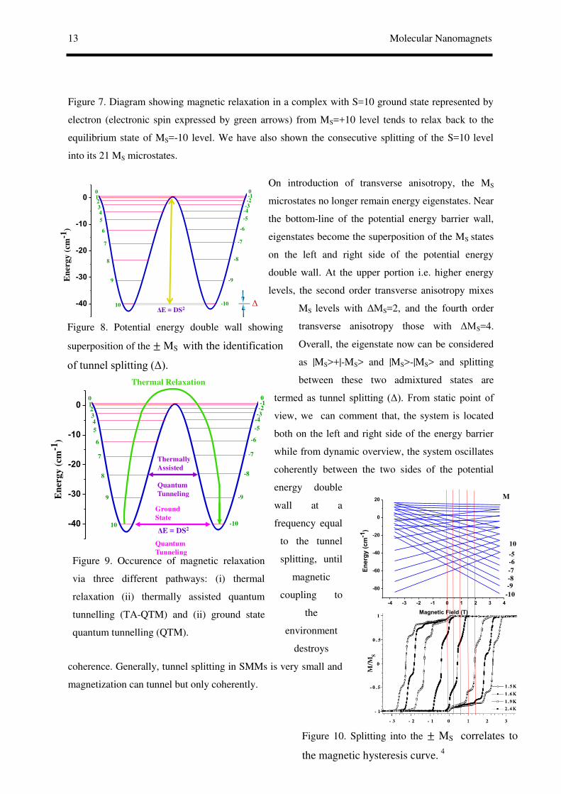
Figure 9. Occurence of magnetic relaxation
via three different pathways: (i) thermal
relaxation (ii) thermally assisted quantum
tunnelling (TA-QTM) and (ii) ground state
quantum tunnelling (QTM).
Figure 10. Splitting into the ± MS correlates to
the magnetic hysteresis curve. 4
Figure 8. Potential energy double wall showing
superposition of the ± MS with the identification
of tunnel splitting (Δ).
Figure 7. Diagram showing magnetic relaxation in a complex with S=10 ground state represented by
electron (electronic spin expressed by green arrows) from MS=+10 level tends to relax back to the
equilibrium state of MS=-10 level. We have also shown the consecutive splitting of the S=10 level
into its 21 MS microstates.
On introduction of transverse anisotropy, the MS
microstates no longer remain energy eigenstates. Near
the bottom-line of the potential energy barrier wall,
eigenstates become the superposition of the MS states
on the left and right side of the potential energy
double wall. At the upper portion i.e. higher energy
levels, the second order transverse anisotropy mixes
MS levels with ΔMS=2, and the fourth order
transverse anisotropy those with ΔMS=4.
Overall, the eigenstate now can be considered
as |MS>+|-MS> and |MS>-|MS> and splitting
between these two admixtured states are
termed as tunnel splitting (Δ). From static point of
view, we can comment that, the system is located
both on the left and right side of the energy barrier
while from dynamic overview, the system oscillates
coherently between the two sides of the potential
energy double
wall at a
frequency equal
to the tunnel
splitting, until
magnetic
coupling to
the
environment
destroys
coherence. Generally, tunnel splitting in SMMs is very small and
magnetization can tunnel but only coherently.
01234
5
6
7
8
9
10
0
-6
-7
-8
-9
-10
-5
-4-3-2-1
ΔE = DS2-40
-30
-20
-10
0
En
erg
y (
cm
-1)
Δ
01234
5
6
7
8
9
10
0
-6
-7
-8
-9
-10
-5
-4-3-2-1
ΔE = DS2-40
-30
-20
-10
0
En
ergy (
cm-1
)
Thermal Relaxation
Thermally
Assisted
Quantum
Tunneling
Ground
State
Quantum
Tunneling
-4 -3 -2 -1 0 1 2 3 4
-80
-60
-40
-20
0
20
En
erg
y (
cm
-1)
Magnetic Field (T)
M
-10
-9-8
-7
-6-5
10

Tulika Gupta 14
On application of longitudinal magnetic field, the spin microstates change energy according to the
Zeeman interaction which leads to the crossing of the microstates at certain levels. At these fields
transverse anisotropy mixes the ± MS levels enabling the tunnelling of magnetization (QTM). The
two ± MS levels of double wall are degenerate or in resonance with respect to each other in absence
of magnetic field(Figure 11).
(a) (b) (c)
Figure 11. Three different possible shapes of the double well potential are (a) Showing transition/QTM between the ground state degenerate ± MS levels. (b) no ground state transition possible between non-degenerate energy levels. (c) On relocating the ground state ± MS levels , again the QTM becomes a possible pathway.
It is worthwhile to mention that, magnetism detected in a single molecule differes in its source as
compared to the origin of classical magnetism. SMMs are nanoclusters in which molecular unit may
possess several paramagnetic ions/electronic spins. A SMM contains substantial potential energy
barrier for reorientation of the magnetization direction. If the magnetic moments of individual
molecules in a crystal of a SMM are oriented in parallel direction, the temperature is reduced, the
magnetic field is removed, the SMM would remain magnetized along with the parallel spins at low
temperatures. The prerequisite to exhibit SMM characteristics are to have large ground spin state (S)
and appreciable amount of magnetic anisotropy (zero-field splitting). To be an active SMM, a
molecule has to show relaxation of magnetization below c characteristic blocking temperature (TB)
which originates from large spin ground state (S, large number of unpaired electrons) in combination
with the presence of large,negative Ising (easy axis) type of magnetic anisotropy(zfs,D) whose cut-off
values are being provided by S2|D| or (S2-1/4) |D| for integer and half-integer spins respectively.
The slow relaxation of magnetization in SMMs arise basically due to the presence of an energy barrier
in order to overcome the reversal of magnetic moment and gets backs to the equilibrium
magnetization state compatible to the behaviour of super-paramagnetic materials.
Super-paramagnetic behaviour takes place when a single magnetically ordered domain possesses
reorientation barrier compatible to the thermal energy. This enables free magnetization flipping,
property similar to that observed in a paramagnet. In presence of external magnetic field, this behaves
like a a paramagnet till the temperature is sufficiently decreased such that the energy barrier cannot be
01234
5
6
7
8
9
10
0
-6
-7
-8
-9
-10
-5
-4-3-2-1
ΔE = DS2-40
-30
-20
-10
0
En
ergy (
cm-1
)
Not
possible
possible

15 Molecular Nanomagnets
easily dealt with. Hence, blocking of magnetization takes place below a blocking temperature (TB),
and the super-paramagnet reverts back to its usual bulk behaviour (ferro/antiferro/ferri magnetic
materials).As mentioned before that, axial anisotropy(D) enforces magnetic moment alignment in
either parallel(spin-up) or antiparallel(spin-down) alignment with respect to the quantization (easy)
axis.,energy barrier for the magnetization reversal or energy needed to reorient the magnetization to
its equilibrium state can be represented as S2|D|. For each S spin state, 2S+1 spin projections or energy
states have been procured. In the absence of any transverse anisotropies or field, energy states with
equal bur opposite spin projections (± MS) will retain degeneracy in zero magnetic field. The energy
eigenvalues for each eigenstate can be described as, E(ms) = D ms2 (ms is the spin projection along the
z axis; the ground state for the system is the greatest magnitude of the spin projection (ms = ± S),
since D is negative. The axial anisotropy defines a quantization axis (z axis in general), for the energy
levels for the system, which are quantized. The energy barrier creates the bistable magnetic state
owing to energetic preferential orientation in +z direction or antiparallel in –z direction.
In absence of any magnetic field, anisotropy gets introduced within a system which also brings forth
zero-field splitting parameter. However, in presence of external magnetic field Zeeman interaction is
manifested within the molecule in terms of magnetic anisotropy. In an external magnetic field, the
Zeeman energy of an electron relies on the alignment of the magnetic field with respect to the spin
projection along the magnetic field. The energy of the Zeeman interaction is correlated to the strength
of the external magnetic field through a proportionality factor. Zeeman energy depends upon Bohr
magneton, external magnetic field strength, Lande factor, and spin operator of the molecule. Zero-
field anisotropy has profound impact on magnetic properties and magnetic hardness is correlated to
the magnetoanisotropy. Qualities of a super-paramagnet is seen within an SMM which also shows
both frequency-dependent out-of-phase ac magnetic susceptibility(Fig 12) and hysteresis in a graph of
magnetization vs applied dc magnetic field which are characteristics of magnetic materials.
AC susceptibility studies reveal that at several oscillation frequencies can be utilised in order to
determine the true effective energy barrier for magnetization relaxation (Ueff) as at the χm’’ peak
maximum magnetization relaxation rate (1/τ, where τ is the relaxation time) equals to the angular
frequency (2π ) of the oscillating field. Hence, out-of-phase ac measurements at various oscillation
frequencies are a variable source of relaxation rate vs T kinetic data that can be fitted to the Arrhenius
equation:
1/τ = (1/τ0) exp (-Ueff/KT) and ln (1/τ)= ln (1/τ0) -Ueff/KT
The relaxation time in an SMM is expected to follow the Arrhenius equation (as shown by straight
line in the adjacent figure 13). Besides showing the aforementioned classical properties, SMMs also
show quantum properties i,e, quantum tunnelling of magnetization (QTM) through the energy barrier.

Tulika Gupta 16
Figure 12. In-phase and out-of-phase AC
magnetic susceptibility of
[CrIII2DyIII
2(OMe)2(bdea)2(acac)4(NO3)2] 6
Figure 13. Plot of the natural logarithm of the
magnetization relaxation rate vs 1/T for
[CrIII2DyIII
2(OMe)2(bdea)2(acac)4(NO3)2] 6
Magnetic hysteresis is one another unique property associated with SMMs, observed at low
temperature so that each molecule behaves as a tiny magnet. This leads to the observation of “steps”
in the hysteresis loop and imply the presence of quantum mechanical “short-cuts” for the reversal of
the magnetic moment. Such steps clearly reveal the presence of QTM, and take place only when the
mS levels on each side of the potential energy double
well become degenerate resulting from the applied
magnetic field which further induces tunnelling of the
magentization vector. So, as discussed before, QTM
can be described as the tunnelling of the magnetization
vector from a energy level on one side of the classical
energy barrier to the energy state on the other side.
Phonon assisted QTM occurs on excitation of the
magnetization vector to higher energy ms levels which
subsequently tunnels through the energy barrier.
Hence, we can say that increasing the S and D will
instill the quest of obtaining improved SMMs. While,
increasing S value proportionate the enhancement of
the number of unpaired electrons which requires
vigorous experimental endeavour and to some extent
cumbersome also. Hence, the focus of obtaining
better SMMs have been diverted towards the
synthesis of complexes possessing metal ion with
large magnetic anisotropy. Complexes
possessing single metal ion with large
magnetic anisotropy have been proved their
ability to show excellent energy barrier for
magnetization reversal and increased blocking
temperature. 18 5 19
20
21
22, 23
24
25 26, 27
The anisotropy barrier can be determined from
magnetic susceptibility measurements in a a
very small dynamic or alternating current (ac)
magnetic field, which can be undertaken either
in zero static direct current (dc) field or in an
applied dc field. During the performance of
such experiments, in-phase (χ’) and out-of-

17 Molecular Nanomagnets
Figure 14. Crystal structure of first ever invented
SMM [Mn12O12(O2CMe)16(H2O)4]
phase (χ’’) components of the magnetic susceptibility are measured as a function of the variable ac
frequency ( ). The χ’’ vs plot enables the estimation of relaxation time τ from τ = 1/2π , is the
peak maximum (figure 13; inset). The relaxation dynamics are expressed by a relaxation time τ at a
particular temperature and frequency which further permits determination of the anisotropy barrier
from the equation ln (1/τ)= ln (1/τ0) -Ueff/KT . The Ueff values can be extracted from the linear section
of the ln τ vs 1/T plot, this depicts a regime where relaxation is thermally activated.
Measure of the success of an SMM is whether or not the field dependence of the magnetization shows
hysteresis. If a molecule is indeed “magnetic”, then, after being subjected to a reverse magnetic field
(H) and subsequently returned to zero-field conditions, it will display nonzero magnetization (M).
This phenomenon is also temperature dependent; however, other factors such as the field sweep rate
determine the maximum temperature (the blocking temperature, TB) at which M(H) hysteresis is
observed. It is possible to compare SMMs characterized using different sweep rates by defining the
blocking temperature as the temperature at which the magnetic relaxation time is 100 s. Many SMMs
show M(H) hysteresis; however, all current examples require liquid helium cooling, and one of the
major challenges is to raise the blocking temperature to levels that will be more convenient for the
development of device applications. Hence, recent extensive research on SMMs have been
undergoing towards achieving high temperature single molecule magnets. 28
. §1.1.2.detailed analysis of the properties of first ever discovered mn12ac molecule:
The first SMM was discovered in a coordination complex made of 12 oxide and acetate bridged
manganese ions, with formula
[Mn12O12(O2CMe)16(H2O)4](Mn12Ac) have
received appreciable attention due to its unusually
large magnetic moment and magnetic bistability.
This complex shows large S=10 ground state, and
associated with large negative magnetocrystalline
anisotropy barrier of 70K which has resulted a
characteristic relaxation time and magnetic
hysteresis below a blocking temperature (TB) of
3K. The magnetic core of Mn12-ac has four Mn4+
(S=3/2) ions in a central tetrahedron
surrounded by eight Mn3+ (S=2) ions. The
ions are coupled by superexchange through
oxygen bridges with the net result that the four inner and eight outer ions point in opposite directions,
yielding a total spin = 10.
Tulika Gupta 18
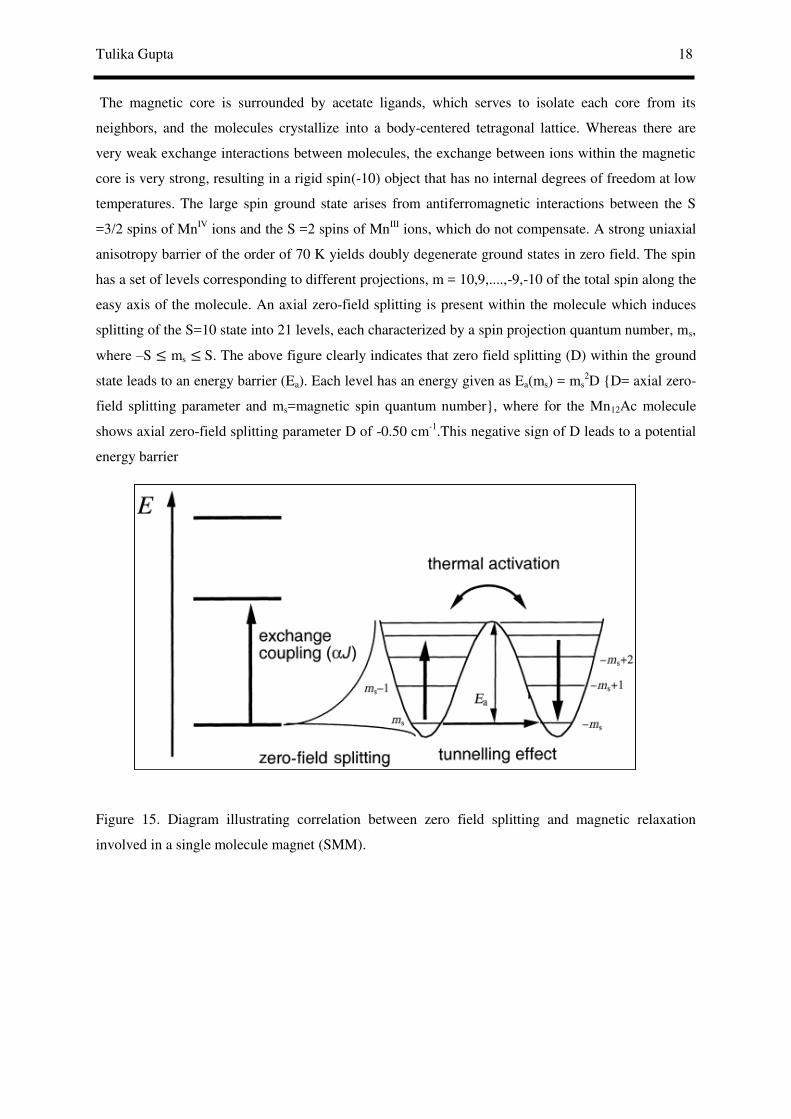
The magnetic core is surrounded by acetate ligands, which serves to isolate each core from its
neighbors, and the molecules crystallize into a body-centered tetragonal lattice. Whereas there are
very weak exchange interactions between molecules, the exchange between ions within the magnetic
core is very strong, resulting in a rigid spin(-10) object that has no internal degrees of freedom at low
temperatures. The large spin ground state arises from antiferromagnetic interactions between the S
=3/2 spins of MnIV ions and the S =2 spins of MnIII ions, which do not compensate. A strong uniaxial
anisotropy barrier of the order of 70 K yields doubly degenerate ground states in zero field. The spin
has a set of levels corresponding to different projections, m = 10,9,....,-9,-10 of the total spin along the
easy axis of the molecule. An axial zero-field splitting is present within the molecule which induces
splitting of the S=10 state into 21 levels, each characterized by a spin projection quantum number, ms,
where –S ≤ ms ≤ S. The above figure clearly indicates that zero field splitting (D) within the ground
state leads to an energy barrier (Ea). Each level has an energy given as Ea(ms) = ms2D {D= axial zero-
field splitting parameter and ms=magnetic spin quantum number}, where for the Mn12Ac molecule
shows axial zero-field splitting parameter D of -0.50 cm-1.This negative sign of D leads to a potential
energy barrier
Figure 15. Diagram illustrating correlation between zero field splitting and magnetic relaxation
involved in a single molecule magnet (SMM).

19 Molecular Nanomagnets
Figure 16. Splitting of S=10 level into its
corresponding ± 21 mS levels.
Figure 17. Magnetic hysteresis and its
corresponding parts.
between the spin-up (ms= -10) and spin-down (ms= 10)
orientations of the magnetic moment of individual
Mn12Ac molecule. Moreover, in order to flip the spin of
a Mn12 molecule from along the +z axis to along the -z
axis of the disc-like Mn12O12 core, it takes some energy
(beside figure) to reorient the spin via the perpendicular
ms=0 state. This is an easy axis type of anisotropy. If this
barrier is appreciable, the spin of an SMM can be
magnetized in one direction. For a thermally activated
process, the time for the reorientation of the
magnetization depends exponentially on the
height of the barrier. Mn12Ac is magnetic
field and then removing the field, the relaxation of the magnetization is so slow that after two months
the magnetization is still about 40% of the saturation (i.e., largest) value. At 1.5 K, the half-life for
magnetization decay is hardly measurable because it is too long. It has been conclusively established
that the slow magnetization relaxation shown by an SMM is due to an individual molecule rather than
to long range ordering as observed in nanoscale magnetic domains of bulk magnets. Support for this
conclusion comes from several experiments, such as magnetization relaxation data for frozen
solutions or polymer-doped samples, the absence of any anomaly in heat-capacity measurements (no
long-range magnetic ordering), and high-frequency electron paramagnetic resonance (HFEPR) data.
When a sample of Mn12Ac molecule is exposed to a large external magnetic field, the ms= -10
state is greatly stabilized in energy relative to the
ms= +10 state. All of the molecules have their
spins aligned with the external field; all of the
molecules are in the ms = -10 state, and the
magnetization is saturated. If the external field is
cycled to zero, the magnetization M is frozen by
the presence of the barrier and only very slowly
tends to the equilibrium value (M=0). Thus, a
remanent magnetization is observed. A
negative field reduces the height of the barrier
and unfreezes the spins, thus allowing a rapid
reversal of the magnetization. A hysteresis loop is therefore observed, which has a molecular and
dynamical origin. The width of the loop (i.e., the coercive field) depends on the temperature as well as
the rate of sweep of the magnetic field. Large coercive fields of several Tesla have been observed for
1 below 2 K. The important feature is that at zero field, the magnetization of Mn12Ac can be either
positive or negative, depending on the history of the sample. Therefore, it is possible in principle to
ms = S ms = -S
up down
M
H
+ Steps in the magnetisation curve
Msaturation
Hcoercive
Mremnant

Tulika Gupta 20
Figure 18. Magnetic bistability, hysteresis and
remanent magnetization in Mn12Ac hard magnet.
store information in one single, bistable molecule.
The magnetic anisotropy of the ground state of
Mn12Ac largely results from the magnetic
anisotropy of the eight MnIII ions. The bonding at
each MnIII ion is such that two trans- bonds are
longer than the other four (in what is called a
Jahn–Teller elongation). These “crystal-field”
distortions, together with a spin-orbit interaction,
establish a zero-field splitting at each MnIII ion.
Thus, it is the vectorial projection of single-
ion anisotropies onto the S = 10 ground state
that gives rise to the easy axis type of
magnetoanisotropy. SMMs have huge potential applications in high-density magnetic memories,
magnetic refrigeration, molecular spintronics and quantum computing devices and used as
multiferroic materials with magnetoelectric effect. Mn12Ac is a hard magnet and known for its
bistability i.e. : in zero field the magnetisation can be positive or negative depending of the story of
the sample. This molecule is magnetically saturated in 3T magnetic field and retains magnetization
even upon removal of magnetic field. We need to apply 1T of magnetic field in order to bring back
the magnetization to zero and saturation can be achieved again by application of 3T magnetic field in
the downwards direction. If we switch off the magnetic field, magnetization really persists while
demagnetizing the system again requires the application of substantial magnetic field. For Mn12Ac
molecule the relaxation time at 2K is order of months and below 1.5K relaxation time is of the order
of 50 years and it has application in magnetic memory devices. The steps in the curve (figure 18)
indicate the occurrence of tunnelling of the electronic spins in Mn12Ac molecule.
Now, owing to the dependence of slow relaxation in magnetic materials on the opening of the
magnetization vs field loop (hysteresis loop), gaining deeper insights into the magnetic hysteresis
properties have become essential. In molecular magnets, hysteresis do not arise due to the irreversible
growth of domains with the orientations of the magnetic moments parallel to the field, instead it relies
on the fact that magnetization of the materials relax back at extreme slow rate compared to the time
needed to sweep the field. Hence, magnetization of the magnetic material fails to reach the
equilibrium value in the time-window of the experiment. Dynamics of the magnetic material solely
dictates the width of the hysteresis loop. In molecular magnets, the magnetic field could have weird
effect on the magnetization dynamics. This entails the accurate recording of the hysteresis loop in the
exploration of the dynamics as compared to the well-known magnetic materials.
-3 -2 -1 0 1 2 3
-20
-10
0
10
20
T=2.1K
MA
GN
ET
IZA
TIO
N ( B
)
MAGNETIC FIELD (T)
Coercive Field
Remnant Magnetisation

21 Molecular Nanomagnets
Figure 19. Top: Splitting of the S level to its Ms
levels and bottom: occurrence of QTM.
Figure 20. Top: non-interacting energy levels and
bottom: non-degenerate energy states between ±
MS = 10 states.
Given the two ground states are degenerate, the
magnetization will try to pass through the consecutive
all higher energy levels in order to come back to the
equilibrium state. This will be deterred if magnetization
tunnel through (as shown in the Figure 152) amidst the
expected energy levels which will try to cut down the
energy barrier for reorientation of magnetization. Such
incident is termed as quantum tunnelling of magnetization
(QTM) which is induced by breakage of degeneracy of
the ground state levels, perturbation of which is found to
instigate QTM in the whole magnetic phenomena of a
molecule. QTM equates to a loss of magnetization and is
witnesses by steps in experimental loops. Admixing of
degenerate states are found to induce QTM. In presence of
magnetic field, the ground state levels will no longer
remain degenerate (like figure 11b) and will for SMMs
long time is needed to get back to the equilibrium
state of magnetization.
Given the energy levels are degenerate, no
interaction occurs between these levels(non-interacting state shown
in figure 20,top). This interaction can be introduced by low
symmetry components of the crystal field by hyperfine fields
(provided by magnetic nuclei 55Mn) by dipolar fields caused by
neighbouring molecules. Hyperfine fields broaden the levels and are
still functioning at 100 mK. To observe QTM following conditions
need to be fulfilled (i) degenerated wave functions must
superimpose (ii) a transversal field must couple the two wave
functions (iii) coupling should split the two levels resulting tunnel
splitting (iv) tunnelling effect is related to tunnel
splitting and the energy barrier. Such perturbation is
basically introduced by the presence of transverse
anisotropy (along XY plane) basically due to
deviation from the symmetry.
QTM is basically incurred onto large transverse anisotropy. For larger Ms values, smaller admixture
of the two wavefunctions have resulted slowing down of the tunnelling rate. The particle oscillates
E=DS2
M=-SM=S

Tulika Gupta 22
Figure 21. Admixing of the energy levels decreases
between for ± MS values.
coherently between the two
sides of the potential well at a
frequency equal to the tunnel
splitting. In our previously
discussed SMM Mn12Ac
molecule tunnel splitting is
found to be very small (in the order of 10-10
K).
As energy barrier for reorientation of magnetization depends on spin (S) of the ground state of the
molecule and zero-field splitting (D) enhancement of both the parameters necessitates better SMM
property. Increments in the number of metals do not proportionate the spin state. Instead, underlying
type of magnetic interactions within the molecule determines the S value. Hence, it is necessary to
arrange the metal ions and the bridging ligands in an appropriate manner in order to give rise to high
spin ground state. It is worth mentioning that, large spin never always ensure an SMM with an
accessible blocking temperature (TB) due to the lack in generating large negative zero-field splitting
(D) parameter. For example, MnIII6 complexes have been prepared with an S=12 ground state, but
since the six MnIII ions are arranged in a high-symmetry octahedron, the zero-field splitting is
negligible (D=0) in these complexes. Most importantly, synthesis of complexes with large metal ions
is extremely cumbersome, complicating the generation of better SMMs. It is also noteworthy that,
exerting control over the symmetry of the coordination environments become increasingly difficult
and elaborate/large molecular clusters tend to reduce SMM characteristics significantly. Since more
than two decades, aftermath the discovery of SMMs research focus was synthesising larger clusters
with the hope of obtaining better SMMs which could not be at the par with the expectations. This
entails chemists and physicists to experiment with other dictating parameter (D) for energy barrier for
magnetization reorientation. Hence, magnetic anisotropy is the most crucial property unifying all
SMMs. The physical significance of anisotropy in SMMs is that the magnetic moment of an
individual molecule has a preferred orientation, which does not depend on an external magnetic field,
leading to net magnetization in a bulk sample. If the orientation of the magnetic moment is reversed -
crudely, analogous to flipping spin-up to spin-down then the SMM properties are lost. In order to
wipe the SMM properties in this way, a thermal energy barrier must, in principle, be surmounted: for
the purposes of this review, the energy barrier is referred to as the anisotropy barrier, Ueff, in units of
cm−1 (as opposed to units of K, which are also commonly used). The magnitude of the anisotropy
barrier is one way of comparing the success of different SMMs, and the bigger the barrier, the larger
blocking temperature, the more prominent the SMM properties at higher temperatures. Moreover, fine
control over the symmetry, ligand field and nature of the ligand field is crucial in order to mitigate
perturbations (QTM) and obtain improved SMMs. 29 30-32
Ms=-10 Ms=+10
Ms=-1 Ms=+1
mixing
mixing

23 Molecular Nanomagnets
Figure 22. Crystal structure of [Fe(C(SiMe3)3)2]-
and energies of their 3d orbitals extracted from ab
initio computed analysis
§1.1.3.Transition metal based SMMs and SIMs:
Ever since the discovery of the first SMM, namely the Mn12-acetate compound, considerable efforts
have been devoted to the development of this fascinating area 33, 34,35-39aiming at the enhancement of
both the TB and Ueff . However, the record of the energy barrier of the SMMs was held by the first
Mn12-acetate compound for more than a decade until the discovery of the Mn6 compound.
Among the transition metals, at first VIII/VIV based SMMs i.e. [NEt4][VIII
4O2(O2CEt)7(pic)2],
[VIV15As6O42(H2O)]6+ have been observed which also incorporates polyoxometallate class of
compounds. Mn containing SMMs are
the most ubiquitous class amongst their
other transition congeners ansd studied
extensively owing to the large spin of the
manganese centres in the various
oxidation states, stability of the Mn
complexes under aerobic conditions, the
availability of many Mn complexes/salts
as starting materials and ease of synthesis
of these Mn containing compounds. Several
Mn dimmers, tetrameric clusters have been
reported as SMMs which is also
corroborated by some SMMs possessing Mn metal ions. Besides these, NiII, CoII, CoIII, FeII, FeIII
based SMMs have been vigorously studied in the literature. It is worth mentioning that, first row
transition metal based SMMs are most ubiquitous in the literature. The first attempts to maximize the
anisotropy barrier focused on maximizing S by designing systems with ferromagnetic exchange
coupling. Using this approach, the largest anisotropy barrier and blocking temperature of Ueff = 62
cm−1 and TB ≈ 4.η K, respectively, were reported for the dodecametallic phenolate-bridged cage
[Mn6O2(sao)6(O2CPh)2(EtOH)4] ({Mn6}; saoH2 = 2-hydroxybenzaldehye oxime), which was
determined to have a total spin of S = 12.All these polynuclear transition metal clusters do not exhibit
energy barrier according to the expectation. Moreover, difficulties in synthesis of such large clusters
spur the need towards exploring other alternatives of procuring better SMMs. The first example of a
monometallic 3d SMM was the high spin Fe(II) compound K[(tpaMes)Fe (H3tpaMes = Tris((5-
mesityl-1Hpyrrol- 2-yl)methyl)amine). The Fe(II) ion lies in a trigonal pyramidal geometry, with an
N4 coordination sphere. The bulky ligand promotes the unusual geometry around the metal centre by
impeding access to the second axial site. Owing to the anisotropy of the transition metal ion Easy
synthesis of compounds containing single transition metal ion and owing to their associated magnetic
anisotropy research attention has been focussed towards transition metal based Single Ion Magnets
(SIMs). 40 Recent breakthrough in this field occurred with the discovery of two coordinate linear Fe(I) 41 complex [K(crypt-222)][Fe(C(SiMe3)3)2], which leads to large barrier height of 226 cm-1. Attempts
0
1
2
3
4
5
6
En
erg
y (
10
3 c
m-1
)

Tulika Gupta 24
Figure 23. Crystal structure of [Dy(Htea)(NO3)]6
complex.
to understand the slow magnetic relaxation in Kramers ions with positive axial anisotropy have
outlined the importance of physical considerations beyond the symmetry around a 3d ion, such as the
importance of hyperfine interactions. Control of the relaxation pathways available to a single ion
magnet should allow for improvement in performance as a potential data carrier. The physics of these
compounds and how this relates to other possible applications for nanomagnets, such as quantum
computing, still has wide scope for exploration. To obtain SMMs with high Ueff and TB , highly Ising-
type anisotropy is required for most of the time.
§1.1.4. Lanthanide based SMMs and SIMs:
Large energy barrier and blocking temperature-two important prerequisites of better SMMs are
controlled by high Ising type anisotropy. This entails the inclusion of 4f metal ions which possess
anisotropy alongwith unquenched orbital angular momenta and large spin orbit coupling.
Despite great synthetic efforts, the desired blocking temperatures for better SMM properties remain
very low (below 4K). In this context, lanthanide ions in the periodic table are the most suitable
candidates due to the associated inherent large anisotropy arising from the large unquenched orbital
angular momentum, inert 4f orbitals, large magnetic moment and spin orbit coupling. They also fulfil
the SMM prerequisite of possessing bistable electronic ground
state and lanthanide based SMMs requisite of large mJ/
magnetic moment values. Owing to the large anisotropy, vast
number of lanthanide based good SMMs have been reported in
the literature since last 2-3 years. It is noteworthy that,
lanthanide based SMMs have advantages in diagnostic and
therapeutic radiopharmaceuticals and as luminescent probe to
investigate biomedical systems. Amongst all, Dy(III) based
SMMs prevail owing to the large energy gap between ground
and first excited mJ levels, concomitant high
magnetic anisotropy and Kramers’ ion (odd
number of f electrons) nature of Dy(III) 5 1, 20,
42-46 leading to the observation of bistable ground state irrespective of the ligand field symmetry. This
has resulted extensive study of several polynuclear Dy(III) based SMMs i.e. [Dy4(µ 3-OH)2(µ-
OH)2(2,2-bpt)4(NO3)4-(EtOH)2],[Dy3(µ3-OH)2L3Cl(H2O)5]Cl3, [Dy2ovph2Cl2(MeOH)3] .
[Dy(Htea)(NO3)]6.8MeOH { Figure 23} with large energy barrier.
For lanthanide based SMMs, 47, 48 21, 26
49, 50
24, 51
52
53-59
60-65
66-76 in a given crystal field, the ground
magnetic state of the complex (characterized by the total angular momentum J), splits into MJ
sublevels. In some instances, this leads to a J-splitting in which the levels with higher MJ values are
stabilized with respect to the levels with lower MJ values. This leads to the appearance of a barrier

25 Molecular Nanomagnets
Figure 25. Crystal structure of heterpeptic [TbIII(Pc)(Pc’)] complex in their neutral forms where R1=R2= O(C6H4)-p
tBu. 2
Figure 26. Crystal structure of
[Er(COT)2]- complex. 3
Figure 24. Crystal structure of [Dy4K2O(OtBu)12] showing Ueff=692 K. 1
between the MJ levels explaining superparamagnetic blocking in the SMMs. Of particular interest in
recent years in research area of SMMs77 is exploration of systems containing only one spin carrier
within a molecule and if such molecules exhibit
magnetisation blockade these are called as Single Ion
Magnets (SIMs) as discussed
for transition metal systems.
Large unquenched orbital
angular momentum,
significant intrinsic spin-orbit
coupling and presence of
large number of unpaired
electrons make
the lanthanides
suitable candidates for attaining large
spin-reversal barriers. The early research
on lanthanide SMMs can be dated back to 2003, when Ishikawa et al.
demonstrated that slow relaxation of the magnetization can occur in
mononuclear lanthanide species(SIMs), that is, the double-decker
phthalocyanine lanthanide system [LnPc2]− (Ln = Tb, Dy).
78, 79 Nevertheless, until 2006 the discovery of the
fascinating Dy3 triangle SMMs showing the coexistence of
nonmagnetic ground states and SMM behaviour really stimulated wide interest in the exploration of
pure lanthanide SMM systems with strong local Ising-type anisotropy at metal sites. Therefore,
hundreds of such SMMs including mononuclear, dinuclear and larger lanthanide compounds have
now been discovered to exhibit a high anisotropic barrier for reversing the magnetization and
naturally some remarkable advances follow the experimental and theoretical developments in this
field. However, it is worth noting that in some recently reported SMMs, the temperature dependence
of τ shows obvious deviation from the Arrhenius law, and thus other processes such as Raman, direct
and QTM may be added to the fitting of τ vs. T −1 plots. Remarkably, the highest effective barrier in
multinuclear lanthanide SMM has been as high as 692 K(figure 24) which is almost comparable to the
barrier record of 939 K shown by heteroleptic bis(phthalocyaninate) lanthanide SMM(figure
25).Consistent study towards obtaining better SMMs are ongoing which led to the exploration of
SMMs/SIMs based on other lanthanide ions (Er,Ho,Ce).This is evidenced by possession of large 10K
blocking temperature in complex [Er(COT)2]- (see Figure 26} , zero-field SIM characteristics and
large energy barrier for magnetization reorientation. Hence, advantageous properties of lanthanides

Tulika Gupta 26
require a multi- and interdisciplinary vision of scientific research by bringing together synthetic and
physical chemists as well as physicists to achieve the final goal.
§ 1.1.5. Mixed SMMs:
Heterometallic complexes occupy a special place among SMMs as they offer an alternative to
homometallic transition metal SMMs and often exhibit unprecedented metal topologies and beautiful
structural motifs. This combinational complexes (27a) lead to new molecular species with larger
magnetic anisotropies and higher S values,, the latter arising from the different nature and strength of
the magnetic exchange interaction between the heterospin carriers. This class can be categorised to
3d-3d, 3d-4d,3d-5d,3d-4f, 4f-4f and only 4f ion based complexes5, 25, 26, 42, 51, 52, 62, 79-94,4f-2p type of
complexes.
(a) (b)
Figure 27. Crystal structure of mixed SMMs (a) Ni2Dy3 95 complex showing SMM behaviour with
two relaxations. And (b) structure if [Mn6IIIOsIII]
3+ 96 SMM(a 3d-5d mixed SMM).
§1.1..1. 3d-3d97
SMMs: These classes of compounds are not possible due to the difficulties encountered during their synthesis but still few exists. 39, 98
§1.1.5.2. 3d-4d 99
SMMs: K[(Me3tacn)6MnIIMoIII6(CN)18](ClO4)3 cluster was the first initial example
of a 3d-4d SMM which led to a D value of -0.33 cm-1 and energy barrier for reorientation of
magnetization as 9.94 cm-1 . Three years after the inaugural example {CoII9[W
V(CN)8]6.
(MeOH)24}.]19H2O was reported which exhibited effective barrier height of 19.3 cm-1.
§1.1.5.3. 3d-5d100, 101
SMMs(figure 27b): Tetranuclear (NBu4)4 [Ni{ReCl4(ox)}3] cluster was
discovered in 2006 which remarkably possesses “star-like” structure and shows negative zero-field
splitting of -0.46 cm-1 and SMM characteristics significant hysteresis loop. SMM characteristics has
been detected in another W(V) based cluster {[WV(bpy)(CN)6]2[MnIII(L)]2}.3H2O with barrier height
of 22.2 cm-1.
§1.1.5.4. 3d-4f99
SMMs: The first 3d–4f 102-132 SMMs were reported in 2004: [CuLLn(hfac)2]2 (Ln =
Tb, Dy; H3L = 1-(2-hydroxybenzamido)-2-(2-hydroxy-3- methoxy-benzylideneamino)-ethane)

27 Molecular Nanomagnets
squares with the 3d and 4f metals in an alternated array reported by Matsumoto et al., and the
[Dy6Mn6(H2shi)4(Hshi)2(shi)10(MeOH)10(H2O)2] (H3shi = salicylhydroxamic acid) complex, reported
by PecoraroIn 2011, Brooker, Powell, Chibotaru and co-workers reported the first example of a 3d-4f
SMM prepared using a macrocyclic ligand, [ZnII3DyIII(L44)(NO3)3(MeOH)3]·4H2O. This was rapidly
followed by the independent report, by Nabeshimaand co-workers, of a rare example of an erbium
(III)-based SMM of a closely related macrocycle, [ZnII3ErIII(L45)(OAc)(NO3)2(H2O)1.5
(MeOH)0.5]·H2O·3MeOH. Recently, Long and Rinehart61 proposed simple rules in order to exploit the
lanthanides’ single-ion anisotropy for designing 4f ion based SMMs. According to their theory, to
maximize the anisotropy of oblate ions (Ce(III), Pr(III), Nd(III), Tb(III), Dy(III) and Ho(III)) the
crystal field should be such that the ligand electrons are concentrated above and below the xy plane
i.e. axial coordination mode is preferred. On the other hand, for prolate ions (Pm(III), Sm(III), Er(III),
Tm(III) and Yb(III)) an equatorial coordination geometry is preferred. Many of the reported 4f SMMs
follow this prediction, and it is particularly useful for mononuclear lanthanide SMMs (SIMs). This
simple qualitative way of predicting SMM behaviour could also be used to ascertain whether a
lanthanide ion in a 3d–4f complex will contribute strongly to the complex anisotropy, and thus, to the
SMM properties of the 3d–4f species. However, this must only be considered in a very qualitative
manner. Given the difficulties in factoring out all of the contributions to a polynuclear complex’s
magnetic anisotropy, the relationship between the ligand arrangement around the lanthanide ion in a
3d–4f polynuclear complex and the complex’s axial anisotropy will not be as straightforward as with
mononuclear lanthanide SMMs. Ideally, the most anisotropic 3d metals should be combined with the
right lanthanide to obtain new SMMs: the anisotropy of the 3d–4f complex will be a combination of
the single-ion anisotropies of all the paramagnetic metal centres involved. As with any polynuclear
coordination complex, the synthesis of 3d–4f SMMs most often follows a procedure of serendipitous
self-assembly, where researchers try to provide the best reaction conditions to obtain complexes that
might be new examples of SMMs. This is why there is such a rich structural diversity of 3d–4f
SMMs, as is the case for transition metal SMMs. Of course the counterpart is the lack of control in the
structure and properties of the prepared complexes. In the last few years the targeted substitution of a
3d metal by a lanthanide ion in a known transition metal polynuclear complex has been successfully
done. This method has led to the isolation of 3d–4f complexes, where the position of the lanthanide
ion could be predicted at the synthesis step. The [Mn21DyO20(OH)2(tBuCOO)20(HCO2)4(NO3)3(H2O)7]
complex in figure 28 left, reported by Christou and co-workers in 2011, also shows hysteresis of the
magnetization up to 3 K and has a large energy barrier of 74 K. It is notable that the aforementioned
complex with 74 K Ueff is the largest barrier height reported to date for any 3d-4f based SMMs.
Besides, some of the reported 3d-4f complexes are found to show two relaxation time with two
effective barrier height for magnetization reorientation i.e. [CoIII2DyIII
2(OMe)2(teaH)2(Piv)6] shows
Ueff of 51 and 127 K as obtained from AC measurements. Apart from these, several complexes
combining Tb(III)/Er(III)/Ho(III)/Sm(III) lanthanide ions with Fe(III)/Cr(III)/Mn(II)/Co(II) have been
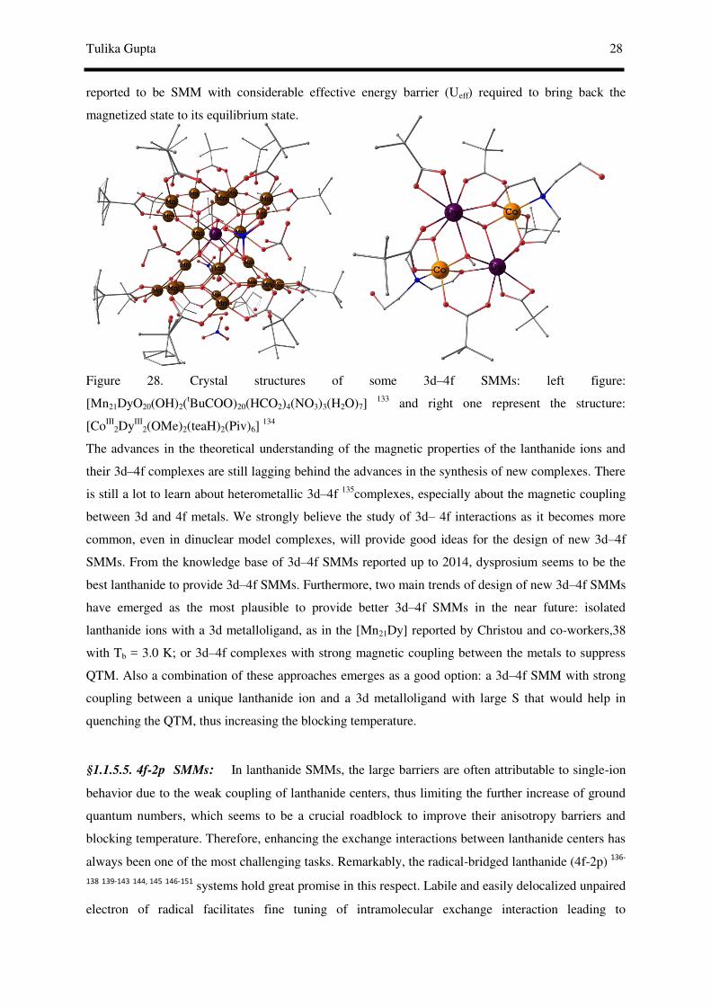
Tulika Gupta 28
reported to be SMM with considerable effective energy barrier (Ueff) required to bring back the
magnetized state to its equilibrium state.
Figure 28. Crystal structures of some 3d–4f SMMs: left figure:
[Mn21DyO20(OH)2(tBuCOO)20(HCO2)4(NO3)3(H2O)7]
133 and right one represent the structure:
[CoIII2DyIII
2(OMe)2(teaH)2(Piv)6] 134
The advances in the theoretical understanding of the magnetic properties of the lanthanide ions and
their 3d–4f complexes are still lagging behind the advances in the synthesis of new complexes. There
is still a lot to learn about heterometallic 3d–4f 135complexes, especially about the magnetic coupling
between 3d and 4f metals. We strongly believe the study of 3d– 4f interactions as it becomes more
common, even in dinuclear model complexes, will provide good ideas for the design of new 3d–4f
SMMs. From the knowledge base of 3d–4f SMMs reported up to 2014, dysprosium seems to be the
best lanthanide to provide 3d–4f SMMs. Furthermore, two main trends of design of new 3d–4f SMMs
have emerged as the most plausible to provide better 3d–4f SMMs in the near future: isolated
lanthanide ions with a 3d metalloligand, as in the [Mn21Dy] reported by Christou and co-workers,38
with Tb = 3.0 K; or 3d–4f complexes with strong magnetic coupling between the metals to suppress
QTM. Also a combination of these approaches emerges as a good option: a 3d–4f SMM with strong
coupling between a unique lanthanide ion and a 3d metalloligand with large S that would help in
quenching the QTM, thus increasing the blocking temperature.
§1.1.5.5. 4f-2p SMMs: In lanthanide SMMs, the large barriers are often attributable to single-ion
behavior due to the weak coupling of lanthanide centers, thus limiting the further increase of ground
quantum numbers, which seems to be a crucial roadblock to improve their anisotropy barriers and
blocking temperature. Therefore, enhancing the exchange interactions between lanthanide centers has
always been one of the most challenging tasks. Remarkably, the radical-bridged lanthanide (4f-2p) 136-
138 139-143
144, 145
146-151 systems hold great promise in this respect. Labile and easily delocalized unpaired
electron of radical facilitates fine tuning of intramolecular exchange interaction leading to
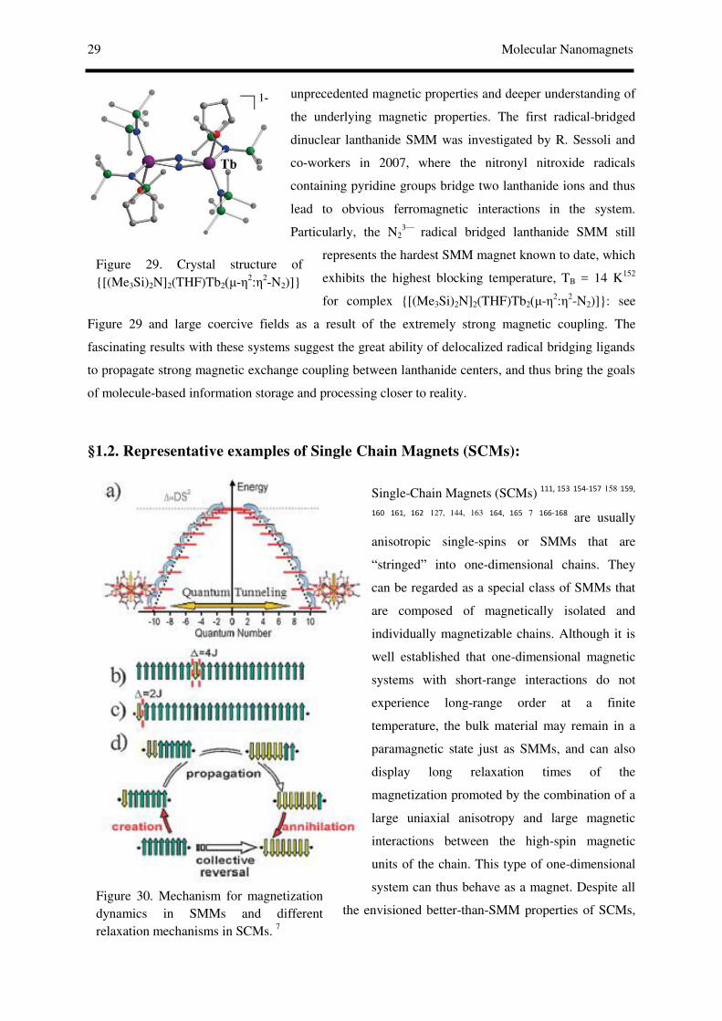
29 Molecular Nanomagnets
Figure 29. Crystal structure of {[(Me3Si)2N]2(THF)Tb2( - 2μ 2-N2)]}
Figure 30. Mechanism for magnetization dynamics in SMMs and different relaxation mechanisms in SCMs. 7
unprecedented magnetic properties and deeper understanding of
the underlying magnetic properties. The first radical-bridged
dinuclear lanthanide SMM was investigated by R. Sessoli and
co-workers in 2007, where the nitronyl nitroxide radicals
containing pyridine groups bridge two lanthanide ions and thus
lead to obvious ferromagnetic interactions in the system.
Particularly, the N23— radical bridged lanthanide SMM still
represents the hardest SMM magnet known to date, which
exhibits the highest blocking temperature, TB = 14 K152
for complex {[(Me3Si)2N]2(THF)Tb2( - 2μ 2-N2)]}: see
Figure 29 and large coercive fields as a result of the extremely strong magnetic coupling. The
fascinating results with these systems suggest the great ability of delocalized radical bridging ligands
to propagate strong magnetic exchange coupling between lanthanide centers, and thus bring the goals
of molecule-based information storage and processing closer to reality.
§1.2. Representative examples of Single Chain Magnets (SCMs):
Single-Chain Magnets (SCMs) 111, 153 154-157
158
159,
160
161, 162 127, 144, 163
164, 165
7
166-168 are usually
anisotropic single-spins or SMMs that are
“stringed” into one-dimensional chains. They
can be regarded as a special class of SMMs that
are composed of magnetically isolated and
individually magnetizable chains. Although it is
well established that one-dimensional magnetic
systems with short-range interactions do not
experience long-range order at a finite
temperature, the bulk material may remain in a
paramagnetic state just as SMMs, and can also
display long relaxation times of the
magnetization promoted by the combination of a
large uniaxial anisotropy and large magnetic
interactions between the high-spin magnetic
units of the chain. This type of one-dimensional
system can thus behave as a magnet. Despite all
the envisioned better-than-SMM properties of SCMs,

Tulika Gupta 30
Figure 31. Various synthetic approach for different SCMS.
successful examples of SCMs are still much fewer than SMMs, thus making the study of SCMs a
field not only fundamentally stimulating but potentially rewarding with possibility of developing
cutting-edge molecule based magnetic materials and corresponding technologies. In the adjacent
figure 30 a) represents Double wall potential responsible for slow relaxation of magnetization in
SMMs b) Glauber dynamics for an infinite chain c) GD for finite-size effects d) an alternative
mechanism for short chains involving the collective reversal of all spins.
Although SMMs and SCMs have in common the blocking of the magnetization, which is associated
to a large easy-axis magnetic anisotropy, the basic physics of SCMs is only partially similar to that of
SMMs, and the competition with different mechanisms of slow relaxation of the magnetization, like
spin glass behavior must always be checked. Both SCMs and SMMs require a strong easy-axis
magnetic anisotropy and weak magnetic interactions but the physical mechanisms are quite different.
In SMMs, the ground multiplet S is split in zero field in such a way that the two states with MS = ± S
lie lowest on each side of a double-well potential. To overcome the barrier ∆=DS2 , generated solely
by the magnetic anisotropy, the spin has to climb up all the other MS states via spin–phonon
interactions, following the extended Orbach process. The model behind the slow dynamics of SCMs
is Glauber dynamics (GD), that was originally developed for 1D Ising ferromagnets and had found
large application to different subjects before the advent of SCMs. The relaxation process begins with
the reversal of one spin in the chain. An Ising system can only assume two orientations and this initial
reversal will cost an energy ∆= -4J or -
4JS2 , if spins different from unity are
assumed, due to the magnetic exchange
interactions J between two neighbouring
spins. In SCMs, ∆ depends on J and it is
thus useful to produce chains with the
highest possible intrachain coupling. The
interesting link between SMMs and
SCMs need to be further theoretically investigated as the 1D organization of interacting SMMs can
instigate substantial enhancement of energy barrier for the reversal of magnetization. Due to the
hysteresis, 0-D systems have been called single-molecule-magnets (SMMs) and 1D systems have
analogously been called single-chain-magnets (SCMs), stressing the fact that the hysteresis arises
from single-molecule or single-chain properties. This immediately implies that SMMs and SCMs can
be made as small as the single constituent units without losing their magnetic properties.

31 Molecular Nanomagnets
Figure 32. Chain structure of Co and Dy radical systems.
In fact the conditions to be met to observe slow magnetic relaxation in 1D materials are rather
stringent: 1) the ratio of the interaction within the chain, J, and that between chains, J', must be rather
high, larger than 104 ; 2) the material must behave as a 1D Ising ferro- or ferrimagnet. First SCM
property was detected in [Co(hfac)2(NITPhOMe)],possesses 1D arrays with a helical structure which
showed slow relaxation of magnetization and hysteresis effects.
According to Glauber’s theory, the origin of the slow
magnetic relaxation was tracked to the large uniaxial
type magnetic anisotropy, strong intrachain magnetic
interaction, and negligible interchain interactions that
hamper the transition to 3D magnetic ordering.
Therefore, the synthetic approaches to build SCM
include two respects: (i) to utilize appropriate bridging
ligands as effective magnetic couplers to link uniaxial,
anisotropic spin carriers, such as Co2+, Ni2+, Mn3+, Fe2+
and lanthanide ions, into 1D chains and (ii) to use
suitable diamagnetic separators so as to make these
chains magnetically well isolated. In SCM literature,
oxygen, cyano, oximate, azido,
oxalato/oxamate, carboxylate, phosphate/
phosphinate and organic radical have been
employed as bridging ligands because they can transport magnetic coupling efficiently. On the other
hand, bulk co-ligands, long spacers, counter ions, etc., have been used for the purpose to reduce
interchain interactions, and some co-ligands themselves also serve as intrachain bridges. The various
combinations of intrachain bridges, metal ions, and separators have led to many SCMs with different
spin structures. the first real homospin FO SCM, Co(bt)(N3)2 169 (see Figure adjacent 164 left), was
reported in 2003 which forms a 1D structure in which there are three independent octahedral Co sites,
leading to a helical arrangement of the Co2+ metal ions along the chain. The versatility of NIT(R)
radicals, has led to the rational design of the first rare-earth-based SCM [Dy(hfac)2NIT(C6H4p-OPh)]
(Fig. 32 right). While a transition to 3D order was observed in [Dy(hfac)2NIT(C2H5)], it has been
possible to suppress 3D ordering and obtain SCM behaviour by rationally introducing bulkier R =
C6H4-OPh groups that suppress interchain magnetic interactions. Replacing the rare-earth-based
SCMs the first family of isostructural SCMs, with tuneable anisotropy of the centres, has been
created.
Although SCM have potential applications as memory devices and record media, their blocking
temperatures are still too low at the moment. The first prospective goal in the synthesis of SCM is to

Tulika Gupta 32
raise the blocking temperature. The promising method to increase the blocking temperature is to
enhance the intrachain coupling by choosing stronger magnetic intermediators.
§2. Characterisation of single molecule magnets:
The presence of zero-field splitting is a signature of magnetism in a quantum system. In non-
magnetic quantum-dot systems, the absence of any zero-field splitting for Zeeman-split levels is
observed universally (as required by Kramers’ Theorem) for tunneling transitions from even (S = 0) to
odd (S = 1/2) numbers of electrons. For odd-to-even transitions, only one spin transition is allowed for
the lowest-energy tunneling transition because of Pauli blocking, but degeneracies at B = 0 are still
generally observed for excited states. In quantum dots made from ferromagnetic nanoparticles, the
presence of zero-field splitting has been observed previously due to magnetic anisotropy that affects
tunneling transitions between states with S≥1/2. The presence of zero-field-split energy levels in four
of our devices therefore demonstrates that tunneling in these devices is occurring via magnetic states
with non-zero magnetic anisotropy.
Using SQUID (Superconducting Quantum Interference Device) magnetometry, it is possible
to measure the magnetization of a sample with a defined mass in various applied fields (up to 7 T)
and at various temperatures (as low as 1.8 K). This data may be fit to the Curie Law, or Curie-Weiss
Law, to yield information about bulk and molar magnetic properties. In addition to applying a static
magnetic field, it is also possible to measure the magnetic susceptibility in an alternating (ac) field
which allows some insight into the dynamics of a magnetic system.
Graphic representations of the temperature dependence of χ, as well as M vs.
H plots, are useful in identifying the magnetic character of a material. When measuring the
magnetization as a function of temperature in a constant applied field, it is possible to calculate the
molar magnetic susceptibility. Plots of χ vs. T are shown for a simple paramagnet ( = 0 K), a
ferromagnetically-coupled material ( = 1 K), and an antiferromagnetically-coupled material ( = -1
K). The plots are different based on their vertical asymptotes (dependent on ), but the curves have
the same shape which can be misleading. For that reason, it is more informative to plot χT vs T which
gives clearer
2 4 6 8 10 12 14 16
0.0
0.1
0.2
0.3
0.4
0.5
FM interaction,
simple paramagnet,
T
T
AF interaction,
0 7 140
2
4
AF interaction,
simple paramagnet,
FM interaction,
T
T
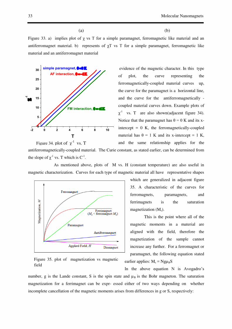
33 Molecular Nanomagnets
Figure 34. plot of χ-1 vs. T
Figure 35. plot of magnetization vs magnetic field
(a) (b)
Figure 33. a) implies plot of χ vs T for a simple paramagnet, ferromagnetic like material and an
antiferromagnet material. b) represents of χT vs T for a simple paramagnet, ferromagnetic like
material and an antiferromagnet material
evidence of the magnetic character. In this type
of plot, the curve representing the
ferromagnetically-coupled material curves up,
the curve for the paramagnet is a horizontal line,
and the curve for the antiferromagnetically -
coupled material curves down. Example plots of
χ-1 vs. T are also shown(adjacent figure 34).
Notice that the paramagnet has = 0 K and its x-
intercept = 0 K, the ferromagnetically-coupled
material has = 1 K and its x-intercept = 1 K,
and the same relationship applies for the
antiferromagnetically-coupled material. The Curie constant, as stated earlier, can be determined from
the slope of χ-1 vs. T which is C-1.
As mentioned above, plots of M vs. H (constant temperature) are also useful in
magnetic characterization. Curves for each type of magnetic material all have representative shapes
which are generalized in adjacent figure
35. A characteristic of the curves for
ferromagnets, paramagnets, and
ferrimagnets is the saturation
magnetization (Ms).
This is the point where all of the
magnetic moments in a material are
aligned with the field, therefore the
magnetization of the sample cannot
increase any further. For a ferromagnet or
paramagnet, the following equation stated
earlier applies: Ms = NgµBS
In the above equation N is Avogadro’s
number, g is the Lande constant, S is the spin state and µB is the Bohr magneton. The saturation
magnetization for a ferrimagnet can be expr- essed either of two ways depending on whether
incomplete cancellation of the magnetic moments arises from differences in g or S, respectively:
-2 0 2 4 6 8 100
5
10
15
20
25
30
FM interaction,
simple paramagnet,
AF interaction,
-1
T

Tulika Gupta 34
Figure 36. Pictorial representation of Magnetic hysteresis
Figure 37. plot of magnetization vs magnetic field
Figure 38. plot of magnetization vs magnetic field in a metamagnet
Ms= N ∆g µB S and Ms= Ng µB ∆S
In these equations, ∆g refers to the difference in the
Lande constant for the two spins of
unequal magnitude and ∆S refers to the difference in
spin.
Another important topic for M vs. H
plots is the presence of hysteresis. This is a memory
effect that can be observed when the magnetization
curve does not follow the same path forwards and
backwards as the applied field is cycled from positive
to negative(adjacent figure 36 where M vs H plot shows
hysteresis) . As the field is applied starting from zero field, the sample becomes magnetized (this
segment of the curve is often omitted for clarity in the adjacent figure 36). As the field is lowered to
zero, the sample retains some magnetization, which is referred to as the remanence. The sample
remains magnetized until the applied field is strong enough in the negative direction to flip the spins;
this field strength is referred to as the coercivity or coercive field (Hcr). The hysteresis loop is
typically centered on the origin since the behavior of the magnetization as the field is reversed follows
the same pattern.
Plots of M vs. H (below figure 37) also reveal
whether the magnet in question is soft or hard. A soft
magnet is magnetized when an external field is applied but
it does not retain its magnetization when the applied field
is removed. This translates into small values of coercivity
and remanence. For an ideal soft magnet, the curve would
follow the same path forwards and backwards as the
applied field is oscillated as illustrated in
adjacent figure. Hard magnets have large values
of coercivity and remanence making them ideal for use as
permanent magnets since they retain magnetization even
when the applied field is removed. The curve in above
figure 37 is an example of a hard magnet, assuming it
is on the same scale as the plot in adjacent figure.
Metamagnetism is the presence of a field
dependent phase transition from an
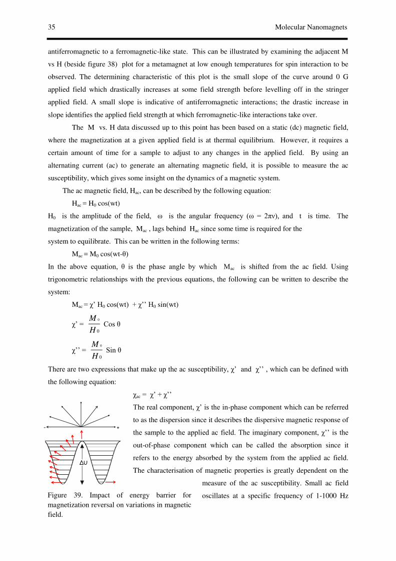
35 Molecular Nanomagnets
Figure 39. Impact of energy barrier for magnetization reversal on variations in magnetic field.
antiferromagnetic to a ferromagnetic-like state. This can be illustrated by examining the adjacent M
vs H (beside figure 38) plot for a metamagnet at low enough temperatures for spin interaction to be
observed. The determining characteristic of this plot is the small slope of the curve around 0 G
applied field which drastically increases at some field strength before levelling off in the stringer
applied field. A small slope is indicative of antiferromagnetic interactions; the drastic increase in
slope identifies the applied field strength at which ferromagnetic-like interactions take over.
The M vs. H data discussed up to this point has been based on a static (dc) magnetic field,
where the magnetization at a given applied field is at thermal equilibrium. However, it requires a
certain amount of time for a sample to adjust to any changes in the applied field. By using an
alternating current (ac) to generate an alternating magnetic field, it is possible to measure the ac
susceptibility, which gives some insight on the dynamics of a magnetic system.
The ac magnetic field, Hac, can be described by the following equation:
Hac = H0 cos(wt)
H0 is the amplitude of the field, ω is the angular frequency (ω = 2π ), and t is time. The
magnetization of the sample, Mac , lags behind Hac since some time is required for the
system to equilibrate. This can be written in the following terms:
Mac = M0 cos(wt- )
In the above equation, is the phase angle by which Mac is shifted from the ac field. Using
trigonometric relationships with the previous equations, the following can be written to describe the
system:
Mac = χ’ H0 cos(wt) + χ’’ H0 sin(wt)
χ’ = 0
0
M
H Cos
χ’’ = 0
0
M
H Sin
There are two expressions that make up the ac susceptibility, χ’ and χ’’ , which can be defined with
the following equation:
χac = χ’ + χ’’
The real component, χ’ is the in-phase component which can be referred
to as the dispersion since it describes the dispersive magnetic response of
the sample to the applied ac field. The imaginary component, χ’’ is the
out-of-phase component which can be called the absorption since it
refers to the energy absorbed by the system from the applied ac field.
The characterisation of magnetic properties is greatly dependent on the
measure of the ac susceptibility. Small ac field
oscillates at a specific frequency of 1-1000 Hz
- +
ΔU
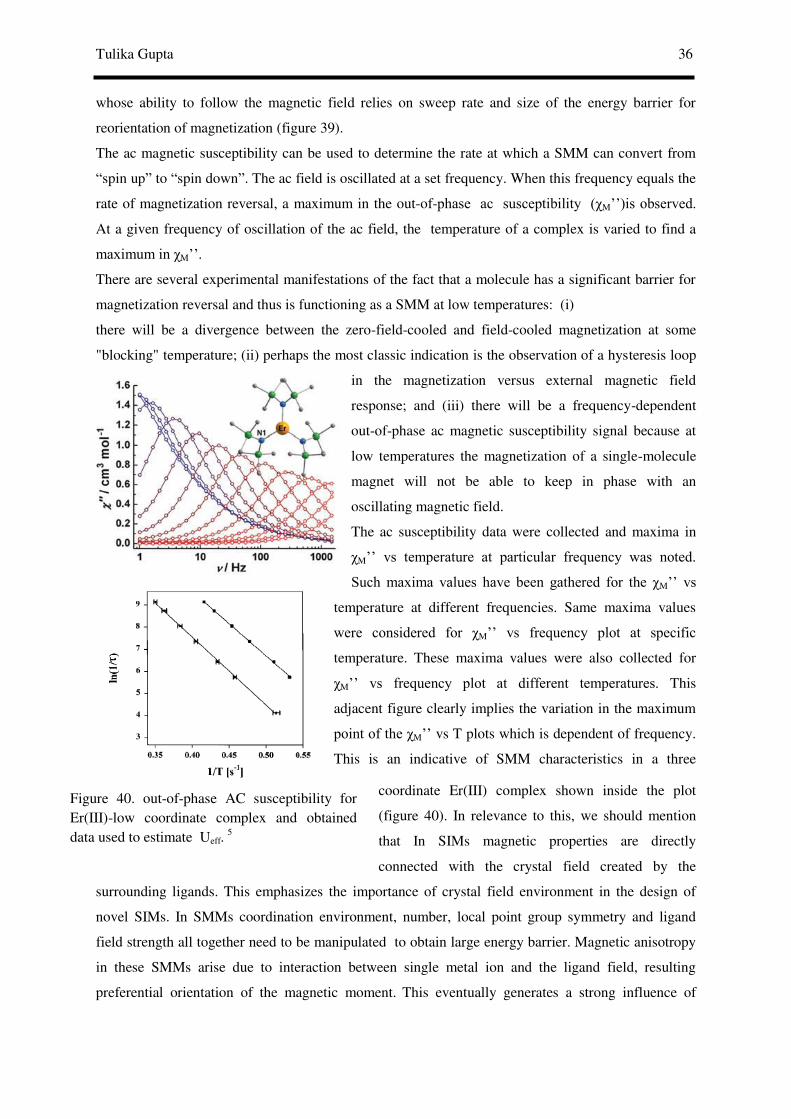
Tulika Gupta 36
Figure 40. out-of-phase AC susceptibility for Er(III)-low coordinate complex and obtained data used to estimate Ueff.
5
whose ability to follow the magnetic field relies on sweep rate and size of the energy barrier for
reorientation of magnetization (figure 39).
The ac magnetic susceptibility can be used to determine the rate at which a SMM can convert from
“spin up” to “spin down”. The ac field is oscillated at a set frequency. When this frequency equals the
rate of magnetization reversal, a maximum in the out-of-phase ac susceptibility (χM’’)is observed.
At a given frequency of oscillation of the ac field, the temperature of a complex is varied to find a
maximum in χM’’.
There are several experimental manifestations of the fact that a molecule has a significant barrier for
magnetization reversal and thus is functioning as a SMM at low temperatures: (i)
there will be a divergence between the zero-field-cooled and field-cooled magnetization at some
"blocking" temperature; (ii) perhaps the most classic indication is the observation of a hysteresis loop
in the magnetization versus external magnetic field
response; and (iii) there will be a frequency-dependent
out-of-phase ac magnetic susceptibility signal because at
low temperatures the magnetization of a single-molecule
magnet will not be able to keep in phase with an
oscillating magnetic field.
The ac susceptibility data were collected and maxima in
χM’’ vs temperature at particular frequency was noted.
Such maxima values have been gathered for the χM’’ vs
temperature at different frequencies. Same maxima values
were considered for χM’’ vs frequency plot at specific
temperature. These maxima values were also collected for
χM’’ vs frequency plot at different temperatures. This
adjacent figure clearly implies the variation in the maximum
point of the χM’’ vs T plots which is dependent of frequency.
This is an indicative of SMM characteristics in a three
coordinate Er(III) complex shown inside the plot
(figure 40). In relevance to this, we should mention
that In SIMs magnetic properties are directly
connected with the crystal field created by the
surrounding ligands. This emphasizes the importance of crystal field environment in the design of
novel SIMs. In SMMs coordination environment, number, local point group symmetry and ligand
field strength all together need to be manipulated to obtain large energy barrier. Magnetic anisotropy
in these SMMs arise due to interaction between single metal ion and the ligand field, resulting
preferential orientation of the magnetic moment. This eventually generates a strong influence of

37 Molecular Nanomagnets
coordination geometries on SIM properties. Thus, magnetic properties are affected not only by
structural and electronic features of the molecule, but also by their surroundings resulting the spin
dynamics method in SIMs a complex and poorly understood problem. Indeed, these processes can
have significant influence on the field dependence of the relaxation time as well as field-induced
multiple relaxation processes. Moreover, Lanthanide containing SIMs are attractive for testing
synthetic design principles for slow paramagnetic relaxation because their properties can be tuned at
will. In general, in a given crystal field, the ground magnetic state of the complex (characterized by
the total angular momentum J), splits into MJ sublevels. In some instances, this leads to a J-splitting
in which the levels with higher MJ values are stabilized with respect to the levels with lower MJ
values. This leads to the appearance of a barrier between the MJ levels explaining superparamagnetic
blocking in the SMMs. Hence, accurate crystal field around the lanthanide ion in order to stabilize the
highest magnetic moment (MS/MJ) of the respective ion and tuning the ligand field appropriately is
an essential criteria to obtain improved SMM properties. Lanthanides prefer to have larger
coordination number which brings forth distortion and destabilizes the desired orientation for the
metal ion. Hence, lower coordination symmetry can be correlated to the higher symmetry which is
expected to stabilize the preferred orientation. This has been proved by recent synthesis of low-
coordinated improved SMMs(worthwhile to mention that, synthesis of low-coordinated molecule is
cumbersome). The aforestated χM’’ vs T plots were used to determine the effective energy barrier (Ueff) of
spin relaxation. Approximation of the resulting relaxation rate (1/τ) versus T dependence(figure
78 in the adjacent figure) by the Arrhenius equation: τ=τ0 exp( Ueff/kT), where τ is the relaxation
time(can be procured from the T and frequency dependent out of phase magnetic susceptibilitydata), k
is the Boltzmann constant, and τ0 is the pre-exponential term, was done. The relaxation rates at a
given temperature can be obtained from ω = 2π =1/τ at the maxima of the χM’’ peaks, where
is the given oscillation frequency.
This is the characteristic behavior for a thermally activated Orbach process, where Ueff is the
effective anisotropy energy barrier,k is the Boltzmann constant, and T is the temperature. A plot of ln
(1/τ) vs 1/T with data can be collected at various ac frequencies which may lead to adjacent figure in
complexes with SMM characteristics. The least square fit to the above equation was expresses as a
solid line in the ln (1/τ) vs 1/T plot. Slope and intercept determines the effective barrier height for
magnetization reorientation and relaxation time respectively.
0
1 1exp( / )effU KT
0ln(1/ ) / ln(1/ )effU KT

Tulika Gupta 38
§3. Prerequisites to design high temperature single molecule magnets:
To-date, Fine control over both the symmetry and nature of the ligand field is crucial in order to
mitigate such perturbations and obtain improved SMM28s. Rinehart and Long proposed using the
intrinsic anisotropic electron density distributions of the lanthanide ions in an extremely tangible
electrostatic manner to design complexes that stabilize these large angular momentum states. The
application of this strategy suggests that an axial ligand field is required for ions whose largest
angular momentum states have oblate spheroid distributions, such as TbIII and DyIII, while an
equatorial field is required for those ions with prolate spheroid states, such as ErIII and YbIII.
Designing a ligand field with the desirable charge distribution will be an effective approach to
enhancing the axial anisotropy of the lanthanide center, given the potential of the electrostatic model
in predicting the nature of single ion anisotropy for lanthanide ions. Elaborating a strongly uniaxial
ligand field to force the magnetization reversal via higher excited energy levels seems to be a very
promising route towards SMM with a high anisotropy barrier. The delocalized radical bridging
ligands can provide an efficient magnetic exchange pathway between lanthanide ions, and thus the
extension of such a system to other radical bridging ligands or larger lanthanide systems might hold
great promise in achieving SMM with a higher blocking temperature. Hence, low coordinated, high
symmetry complexes are the most suitable candidates to show large blocking temperature and suitable
to prepare room temperature single molecule magnets. Complexes with such ligand field environment
are supposed to show zero field SMM behaviour while distortion from idealised geometry induces
perturbation. This leads to the fast zero-field QTM and suppression of SMM characteristics. On
application of magnetic field, QTM can be reduced giving rise to the observation of field induced
SMM behaviour owing to the large mixing of different mJ states.
§4. Synergy between experiment and theory:
Despite enormous synthetic effort expended in making novel examples of lanthanide-based SMMs,
clear understanding of the origin of the slow relaxation of the magnetisation and the mechanisms of
the Quantum Tunnelling of the Magnetisation (QTM) still remains scarce. Understanding the factors
determining the formation of efficient barriers of blocking of magnetisation in SMMs is of primary
importance for the fast advance of this new research area. Slow relaxation of magnetisation in SMMs
can be achieved by effective involvement of anisotropy at the metal sites. Extensive studies on these
SMMs based on lanthanides prove their importance due to their large spin-orbit coupling compared
to the crystal-field splitting of the magnetic 4f-shell. All these studies have concluded the crucial
participation of excited states of the lanthanide ions in the relaxation process of both mononuclear and
polynuclear complexes. The anisotropy axis on the metal ions can be easily determined if the metal

39 Molecular Nanomagnets
centers possess some symmetry elements. Using the angular overlap model, zero-field splitting and
the direction of anisotropy axis can be estimated. However such qualitative ligand-field theories are
extremely complex for lanthanides complexes rendering less accurate predictions. Although numerous
experimental tools such as Inelastic Neutron scattering (INS), multifrequency high-field EPR, field
and orientation dependent magnetic susceptibility have been used to investigate the magnetic
anisotropy, none of them are suffice to resolve the directions of local anisotropy axes accurately.
Here, we (“computational chemists”) can find out the remedy using our computational tools. The only
straightforward way to attain quantitative information about magnetic networks is via fragment
quantum chemistry calculations taking into account the spin-orbit coupling non-perturbatively.
Particularly, the direction of the local anisotropy axis on a metal site is easily gained as the main
magnetic axis of the g tensors of the corresponding Kramers doublet. The single-ion properties of the
4f metal ions are difficult to depict due to the shielded nature of the 4f orbitals resulting weak
exchange interactions. Recent advances in post Hartree-Fock multi-configurational ab initio
methodology have made accurate quantum chemical calculations on paramagnetic 4f compounds
possible. The Complete Active Space Self Consistent Field (CASSCF) method can accurately predict
the magnetic properties of lanthanide complexes, and calculations of this type have become an
indispensable tool for the explanation of increasingly interesting magnetic phenomena. Although
CASSCF ab initio calculations are extremely versatile and implicitly include all the effects required to
elucidate the magnetic properties, the results offer little in the way of chemically intuitive
explanations and attainment of reliable results often requires considerable intervention by expert
theorists equipped with access to powerful computational resources. In addition, the simple but
amenable electrostatic model developed recently provides a crucial input for the theoretical modelling
of the important single ion anisotropy requisite for blocking magnetic moments of lanthanide centers.
Such a model can direct the chemical optimizations for better lanthanide SMMs operating at higher
temperatures.
Normally, the magnetic anisotropy properties of SMMs are described by a spin Hamiltonian with the
axial anisotropy parameter D and the transverse parameter E, and their corresponding higher-order
anisotropy parameters Bnk. However, the giant spin model breaks down when dealing with
lanthanides. The magnetic properties of lanthanide ions are dominated by the internal nature of
the f orbitals. Different from the 3d orbitals of transition metal ions in the ligand field and p orbital of
radicals, f orbitals have strong unquenched orbital angular momentum and effective SOC. Owing to
the SOC, the total angular momentum J, instead of the L and S, becomes the best quantum number.
As a result, the giant spin model that is based on the spin operator cannot be used to analyse the
magnetic properties of a system containing lanthanide.
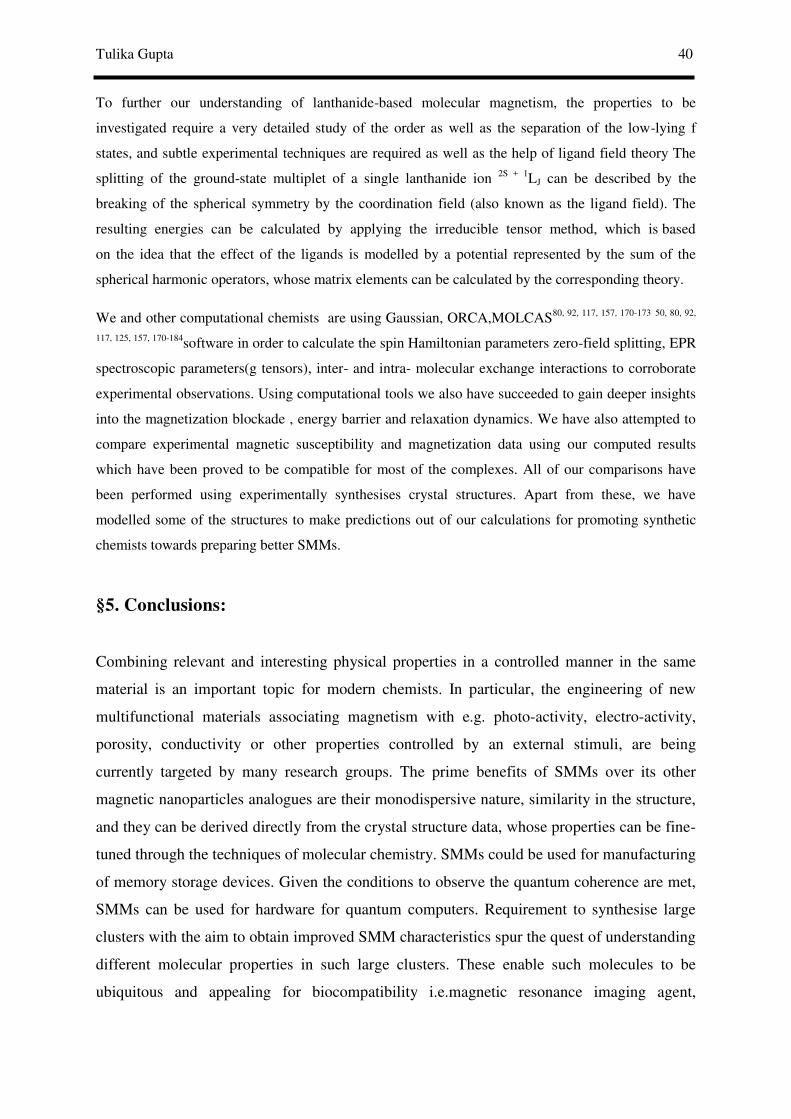
Tulika Gupta 40
To further our understanding of lanthanide-based molecular magnetism, the properties to be
investigated require a very detailed study of the order as well as the separation of the low-lying f
states, and subtle experimental techniques are required as well as the help of ligand field theory The
splitting of the ground-state multiplet of a single lanthanide ion 2S + 1LJ can be described by the
breaking of the spherical symmetry by the coordination field (also known as the ligand field). The
resulting energies can be calculated by applying the irreducible tensor method, which is based
on the idea that the effect of the ligands is modelled by a potential represented by the sum of the
spherical harmonic operators, whose matrix elements can be calculated by the corresponding theory.
We and other computational chemists are using Gaussian, ORCA,MOLCAS80, 92, 117, 157, 170-173 50, 80, 92,
117, 125, 157, 170-184software in order to calculate the spin Hamiltonian parameters zero-field splitting, EPR
spectroscopic parameters(g tensors), inter- and intra- molecular exchange interactions to corroborate
experimental observations. Using computational tools we also have succeeded to gain deeper insights
into the magnetization blockade , energy barrier and relaxation dynamics. We have also attempted to
compare experimental magnetic susceptibility and magnetization data using our computed results
which have been proved to be compatible for most of the complexes. All of our comparisons have
been performed using experimentally synthesises crystal structures. Apart from these, we have
modelled some of the structures to make predictions out of our calculations for promoting synthetic
chemists towards preparing better SMMs.
§5. Conclusions:
Combining relevant and interesting physical properties in a controlled manner in the same
material is an important topic for modern chemists. In particular, the engineering of new
multifunctional materials associating magnetism with e.g. photo-activity, electro-activity,
porosity, conductivity or other properties controlled by an external stimuli, are being
currently targeted by many research groups. The prime benefits of SMMs over its other
magnetic nanoparticles analogues are their monodispersive nature, similarity in the structure,
and they can be derived directly from the crystal structure data, whose properties can be fine-
tuned through the techniques of molecular chemistry. SMMs could be used for manufacturing
of memory storage devices. Given the conditions to observe the quantum coherence are met,
SMMs can be used for hardware for quantum computers. Requirement to synthesise large
clusters with the aim to obtain improved SMM characteristics spur the quest of understanding
different molecular properties in such large clusters. These enable such molecules to be
ubiquitous and appealing for biocompatibility i.e.magnetic resonance imaging agent,
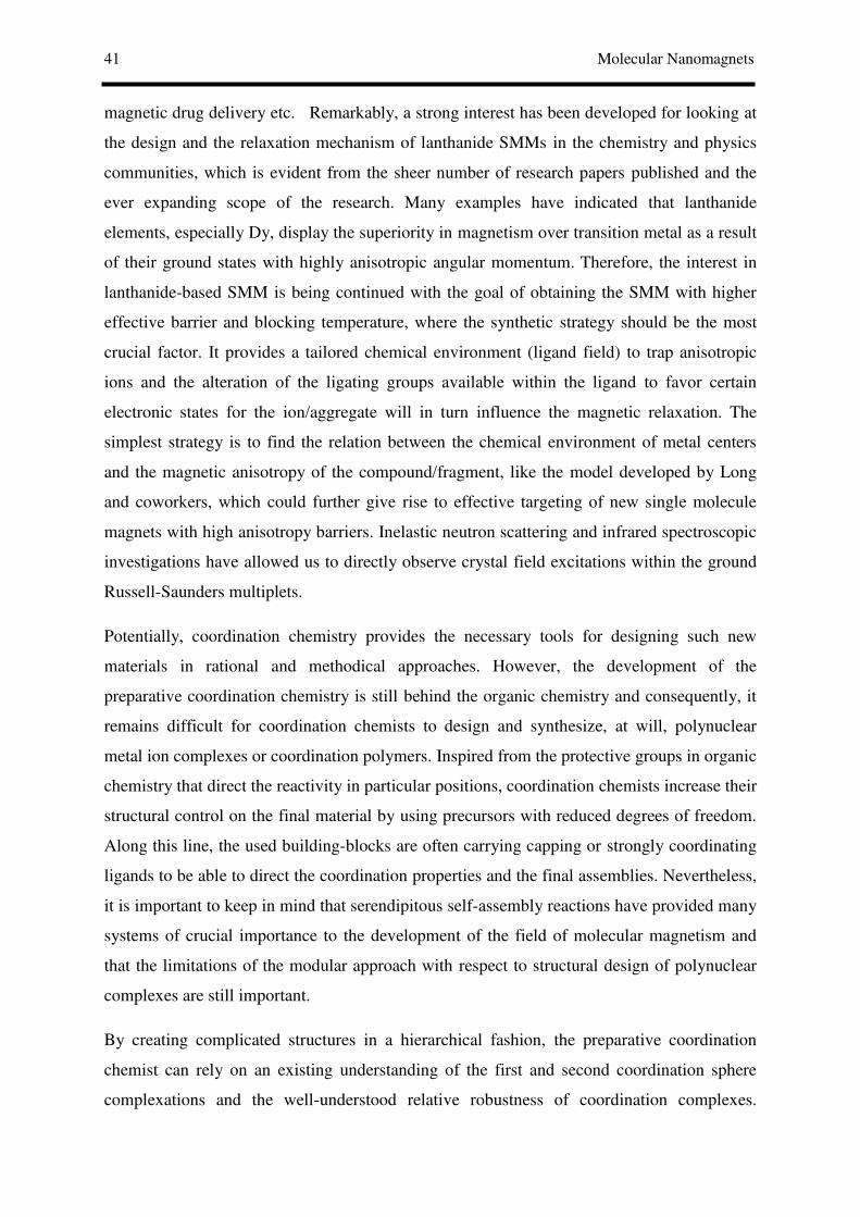
41 Molecular Nanomagnets
magnetic drug delivery etc. Remarkably, a strong interest has been developed for looking at
the design and the relaxation mechanism of lanthanide SMMs in the chemistry and physics
communities, which is evident from the sheer number of research papers published and the
ever expanding scope of the research. Many examples have indicated that lanthanide
elements, especially Dy, display the superiority in magnetism over transition metal as a result
of their ground states with highly anisotropic angular momentum. Therefore, the interest in
lanthanide-based SMM is being continued with the goal of obtaining the SMM with higher
effective barrier and blocking temperature, where the synthetic strategy should be the most
crucial factor. It provides a tailored chemical environment (ligand field) to trap anisotropic
ions and the alteration of the ligating groups available within the ligand to favor certain
electronic states for the ion/aggregate will in turn influence the magnetic relaxation. The
simplest strategy is to find the relation between the chemical environment of metal centers
and the magnetic anisotropy of the compound/fragment, like the model developed by Long
and coworkers, which could further give rise to effective targeting of new single molecule
magnets with high anisotropy barriers. Inelastic neutron scattering and infrared spectroscopic
investigations have allowed us to directly observe crystal field excitations within the ground
Russell-Saunders multiplets.
Potentially, coordination chemistry provides the necessary tools for designing such new
materials in rational and methodical approaches. However, the development of the
preparative coordination chemistry is still behind the organic chemistry and consequently, it
remains difficult for coordination chemists to design and synthesize, at will, polynuclear
metal ion complexes or coordination polymers. Inspired from the protective groups in organic
chemistry that direct the reactivity in particular positions, coordination chemists increase their
structural control on the final material by using precursors with reduced degrees of freedom.
Along this line, the used building-blocks are often carrying capping or strongly coordinating
ligands to be able to direct the coordination properties and the final assemblies. Nevertheless,
it is important to keep in mind that serendipitous self-assembly reactions have provided many
systems of crucial importance to the development of the field of molecular magnetism and
that the limitations of the modular approach with respect to structural design of polynuclear
complexes are still important.
By creating complicated structures in a hierarchical fashion, the preparative coordination
chemist can rely on an existing understanding of the first and second coordination sphere
complexations and the well-understood relative robustness of coordination complexes.

Tulika Gupta 42
Furthermore, this modular strategy offers an efficient transfer of the metal ion properties,
imposed by the first coordination sphere, to extended structures. Thus, this approach allows
us to control not only the spatial arrangements, but also the electronic structure of
complicated systems. In this context, many combinations of metal ion modules and bridging
ligands are unexplored to design new molecule-based magnetic materials including SMMs
and related materials.
The ligand field vs oblate/prolate 4f electron density design ideais well illustrated by the
dysprosium(III) bis(phthalocyanine) complexes. They are good SMMs in large part because
the stronglyoblate (squashed like a hamburger pattie) character of the dysprosium(III) ion is
enhanced by the provision of electron density from the two macrocycles above and below it
(burger buns), in the axial sites, providing the energy minima (spin up and spin down along
the easy axis), separated by the maximum energy wherethe spin passes through the hard
plane which is orthogonal to the easy axis .These phthalocyanine complexes are good SMMs,
but of course a simple analysis like this does not necessarilymean the Ueff will be high as
there are a number of factors that influence SMM behaviour, including the possibility of
QTM. Despite this caution, these general principles have moved researchers on from
selecting terbium(III) and dys-prosium(III) simply because of the magnetic anisotropy
conferred by strong spin–orbit coupling, to understanding how to exploit that anisotropy by
careful ligand design, and indeed to use ligand design to also exploit the anisotropy particular
to other, prolate, 4f ions.
It may be helpful to newcomers to the SMM field to point out that only two of the possible
cases that favour slow relaxation of the magnetisation. Hence, when comparing the mixed 3d-
4f monolanthanide SMMs with the purely 4f monometallic analogues, whilst there is a
marked difference in the average value of Ueff, neither cate-gory of SMMs can be said to be
more promising than the other with regard to practical applications, as all of them have
extremely low TBvalues (<8 K). Any applications of the best of the present SMMs would
therefore require operation at below 8 K in order to obtain significant lifetimes over which
the magnetisation is retained. Operation at such low temperatures is extremely expen-sive so
precludes any widespread application of the present SMMs in devices (e.g. memory or
quantum computing). To open up such applications, the blocking temperatures need to be
considerablyimproved (preferably to liquid nitrogen temperatures or higher),and the lifetimes
below TB increased significantly too (preferably to the order of years). Whilst at present this
seems a massive challenge, researchers in the superconductivity field faced a similarly

43 Molecular Nanomagnets
challenging situation, and did make a huge step up in critical temperature, from liquid helium
to liquid nitrogen temperatures, and superconducting materials are now used in a wide range
of commercial applications.
Attempts to understand the slow magnetic relaxation in Kramers ions with positive axial
anisotropy have outlined the importance of physical considerations beyond the symmetry
around a 3d/4f ion, such as the importance of hyperfine interactions. Control of the relaxation
pathways available to a single ion magnet should allow for improvement in performance as a
potential data carrier. The physics of these compounds and how this relates to other possible
applications for nanomagnets, such as quantum computing, still has wide scope for
exploration. The chemical synthesis of these compounds presents a huge opportunity. If
factors such as nuclear spin, symmetry around the metal ion, and modification of ligands are
taken into account, then there are clearly a large number of experimental parameters to be
tuned and explored.
So far, Single Molecule Magnets are a promising path to increase data density. The hurdle
which still has to be overcome is to find a way of connecting the molecules to the
macroscopic world. If this finally becomes possible, the benefit will be a thousand fold
increase in density.
§21. References:
1. R. J. Blagg, L. Ungur, F. Tuna, J. Speak, P. Comar, D. Collison, W. Wernsdorfer, E. J. L. McInnes, L.
F. Chibotaru and R. E. P. Winpenny, Nat Chem, 2013, 5, 673-678. 2. C. R. Ganivet, B. Ballesteros, G. de la Torre, J. M. Clemente-Juan, E. Coronado and T. Torres, Chem-
Eur J, 2013, 19, 1457-1465. 3. K. R. Meihaus and J. R. Long, J Am Chem Soc, 2013, 135, 17952-17957. 4. B. Barbara, L. Thomas, F. Lionti, I. Chiorescu and A. Sulpice, Journal of Magnetism and Magnetic
Materials, 1999, 200, 167-181. 5. P. Zhang, L. Zhang, C. Wang, S. Xue, S.-Y. Lin and J. Tang, J Am Chem Soc, 2014, 136, 4484-4487. 6. S. K. Langley, D. P. Wielechowski, V. Vieru, N. F. Chilton, B. Moubaraki, L. F. Chibotaru and K. S.
Murray, Chemical Science, 2014, 5, 3246-3256. 7. L. Bogani, A. Vindigni, R. Sessoli and D. Gatteschi, Journal of Materials Chemistry, 2008, 18, 4750-
4758. 8. in Magneto-structural correlations in exchange coupled systems, eds. R. D. Willet, D. Gatteschi and O.
Kahn, NATO Advanced Science Institute (ASI) series, Dordrecht,Netherlands:Reidel, 1985, vol. C140. 9. D. Bimberg, M. Grundmann and N. N. Ledenstov, in Quantum Dot Heterostructures, John Wiley &
Sons Ltd., 1998. 10. N. N. Ledentsov, D. Litvinov, D. Gerthsen, G. A. Ljubas, V. V. Bolotov, B. R. Semyagin, V. A.
Shchukin, I. P. Soshnikov, V. M. Ustinov and D. Bimberg, 2002. 11. W. Wernsdorfer, in Advances in Chemical Physics, John Wiley & Sons, Inc., 2001, pp. 99-190. 12. A. O. Caldeira and A. J. Leggett, Physical Review Letters, 1981, 46, 211-214. 13. D. Gatteschi, A. Caneschi, L. Pardi and R. Sessoli, Science, 1994, 265, 1054-1058. 14. R. S. D Gatteschi, J Villain, in Molecular Nanomagnets, Oxford University Press,Oxford, 2006.

Tulika Gupta 44
15. A. J. Tasiopoulos, A. Vinslava, W. Wernsdorfer, K. A. Abboud and G. Christou, Angewandte Chemie
International Edition, 2004, 43, 2117-2121. 16. R. Sessoli, H. L. Tsai, A. R. Schake, S. Y. Wang, J. B. Vincent, K. Folting, D. Gatteschi, G. Christou
and D. N. Hendrickson, J Am Chem Soc, 1993, 115, 1804-1816. 17. L. Bogani and W. Wernsdorfer, Nat Mater, 2008, 7, 179-186. 18. F. Cimpoesu, N. Dragoe, H. Ramanantoanina, W. Urland and C. Daul, Physical Chemistry Chemical
Physics, 2014, 16, 11337-11348. 19. J. Goura, J. Brambleby, P. Goddard and V. Chandrasekhar, Chemistry – A European Journal, 2015, 21,
4926-4930. 20. Y.-L. Wang, B. Gu, Y. Ma, C. Xing, Q.-L. Wang, L.-C. Li, P. Cheng and D.-Z. Liao, CrystEngComm,
2014, 16, 2283-2289. 21. P. Martín-Ramos, M. Ramos Silva, J. T. Coutinho, L. C. J. Pereira, P. Chamorro-Posada and J. Martín-
Gil, European Journal of Inorganic Chemistry, 2014, 2014, 511-517. 22. D. Zeng, M. Ren, S.-S. Bao, J.-S. Feng, L. Li and L.-M. Zheng, Chemical Communications, 2015, 51,
2649-2652. 23. E. Colacio, J. Ruiz, E. Ruiz, E. Cremades, J. Krzystek, S. Carretta, J. Cano, T. Guidi, W. Wernsdorfer
and E. K. Brechin, Angewandte Chemie International Edition, 2013, 52, 9130-9134. 24. L. Ungur, J. J. Le Roy, I. Korobkov, M. Murugesu and L. F. Chibotaru, Angewandte Chemie, 2014, 53,
4413-4417. 25. B. Na, X.-J. Zhang, W. Shi, Y.-Q. Zhang, B.-W. Wang, C. Gao, S. Gao and P. Cheng, Chemistry – A
European Journal, 2014, 20, 15975-15980. 26. S.-S. Liu, J. W. Ziller, Y.-Q. Zhang, B.-W. Wang, W. J. Evans and S. Gao, Chemical Communications,
2014, 50, 11418-11420. 27. K. S. Pedersen, L. Ungur, M. Sigrist, A. Sundt, M. Schau-Magnussen, V. Vieru, H. Mutka, S. Rols, H.
Weihe, O. Waldmann, L. F. Chibotaru, J. Bendix and J. Dreiser, Chemical Science, 2014, 5, 1650-1660.
28. N. F. Chilton, Inorganic Chemistry, 2015, 54, 2097-2099. 29. M. Evangelisti and E. K. Brechin, Dalton Transactions, 2010, 39, 4672-4676. 30. J. R. Friedman and M. P. Sarachik, Annu Rev Conden Ma P, 2010, 1, 109-128. 31. F. Neese and D. A. Pantazis, Faraday Discuss, 2011, 148, 229-238. 32. P. Wang, S. Shannigrahi, N. L. Yakovlev and T. S. A. Hor, Dalton Transactions, 2014, 43, 182-187. 33. D. E. Freedman, W. H. Harman, T. D. Harris, G. J. Long, C. J. Chang and J. R. Long, J Am Chem Soc,
2010, 132, 1224-1225. 34. F. Neese and E. I. Solomon, Inorganic Chemistry, 1998, 37, 6568-6582. 35. E. Colacio, J. Ruiz, A. J. Mota, M. A. Palacios, E. Cremades, E. Ruiz, F. J. White and E. K. Brechin,
Inorganic Chemistry, 2012, 51, 5857-5868. 36. S. D. Jiang, B. W. Wang, G. Su, Z. M. Wang and S. Gao, Angew Chem Int Edit, 2010, 49, 7448-7451. 37. V. Mereacre, M. N. Akhtar, Y. Lan, A. M. Ako, R. Clérac, C. E. Anson and A. K. Powell, Dalton
Transactions, 2010, 39, 4918-4927. 38. D. P. Li, T. W. Wang, C. H. Li, D. S. Liu, Y. Z. Li and X. Z. You, Chem Commun, 2010, 46, 2929-
2931. 39. G. A. Craig and M. Murrie, Chemical Society Reviews, 2015, 44, 2135-2147. 40. C.-M. Liu, D.-Q. Zhang, X. Hao and D.-B. Zhu, Chemistry – An Asian Journal, 2014, 9, 1847-1853. 41. J. M. Zadrozny, D. J. Xiao, M. Atanasov, G. J. Long, F. Grandjean, F. Neese and J. R. Long, Nat
Chem, 2013, 5, 577-581. 42. H. Zhang, S.-Y. Lin, S. Xue, C. Wang and J. Tang, Dalton Transactions, 2014, 43, 6262-6268. 43. D. Aravena and E. Ruiz, Inorganic Chemistry, 2013, 52, 13770-13778. 44. F. Gao, M.-X. Yao, Y.-Y. Li, Y.-Z. Li, Y. Song and J.-L. Zuo, Inorganic Chemistry, 2013, 52, 6407-
6416. 45. N. F. Chilton, D. Collison, E. J. L. McInnes, R. E. P. Winpenny and A. Soncini, Nat Commun, 2013, 4. 46. N. F. Chilton, S. K. Langley, B. Moubaraki, A. Soncini, S. R. Batten and K. S. Murray, Chemical
Science, 2013, 4, 1719-1730. 47. A. K. Mondal, S. Goswami and S. Konar, Dalton Transactions, 2015, 44, 5086-5094. 48. C. Papatriantafyllopoulou, S. Zartilas, M. J. Manos, C. Pichon, R. Clerac and A. J. Tasiopoulos,
Chemical Communications, 2014, 50, 14873-14876. 49. J. J. Le Roy, I. Korobkov and M. Murugesu, Chemical Communications, 2014, 50, 1602-1604. 50. A. Upadhyay, S. K. Singh, C. Das, R. Mondol, S. K. Langley, K. S. Murray, G. Rajaraman and M.
Shanmugam, Chemical Communications, 2014, 50, 8838-8841. 51. S. N. Konig, N. F. Chilton, C. Maichle-Mossmer, E. M. Pineda, T. Pugh, R. Anwander and R. A.
Layfield, Dalton Transactions, 2014, 43, 3035-3038.

45 Molecular Nanomagnets
52. S.-D. Jiang, B.-W. Wang and S. Gao, Springer Berlin Heidelberg, 2014, pp. 1-31. 53. D. N. Woodruff, R. E. Winpenny and R. A. Layfield, Chemical reviews, 2013, 113, 5110-5148. 54. Z.-G. Wang, J. Lu, C.-Y. Gao, C. Wang, J.-L. Tian, W. Gu, X. Liu and S.-P. Yan, Inorganic Chemistry
Communications, 2013, 27, 127-130. 55. J. Vallejo, J. Cano, I. Castro, M. Julve, F. Lloret, O. Fabelo, L. Canadillas-Delgado and E. Pardo,
Chemical Communications, 2012, 48, 7726-7728. 56. A. Venugopal, F. Tuna, T. P. Spaniol, L. Ungur, L. F. Chibotaru, J. Okuda and R. A. Layfield,
Chemical Communications, 2013, 49, 901-903. 57. F. Tuna, C. A. Smith, M. Bodensteiner, L. Ungur, L. F. Chibotaru, E. J. L. McInnes, R. E. P.
Winpenny, D. Collison and R. A. Layfield, Angewandte Chemie International Edition, 2012, 51, 6976-6980.
58. G.-J. Chen, Y. Zhou, G.-X. Jin and Y.-B. Dong, Dalton Transactions, 2014, 43, 16659-16665. 59. D.-K. Cao, R.-H. Wei, Y.-W. Gu, Y. Zhao and M. D. Ward, RSC Advances, 2014, 4, 43064-43069. 60. G. Cucinotta, M. Perfetti, J. Luzon, M. Etienne, P. E. Car, A. Caneschi, G. Calvez, K. Bernot and R.
Sessoli, Angewandte Chemie, 2012, 51, 1606-1610. 61. J. D. Rinehart and J. R. Long, Chemical Science, 2011, 2, 2078-2085. 62. P. I. Girginova, L. C. J. Pereira, J. T. Coutinho, I. C. Santos and M. Almeida, Dalton Transactions,
2014, 43, 1897-1905. 63. M. Ren, D. Pinkowicz, M. Yoon, K. Kim, L. M. Zheng, B. K. Breedlove and M. Yamashita, Inorganic
Chemistry, 2013, 52, 8342-8348. 64. P.-H. Lin, I. Korobkov, W. Wernsdorfer, L. Ungur, L. F. Chibotaru and M. Murugesu, European
Journal of Inorganic Chemistry, 2011, 2011, 1535-1539. 65. M. Jeletic, P. H. Lin, J. J. Le Roy, I. Korobkov, S. I. Gorelsky and M. Murugesu, J Am Chem Soc,
2011, 133, 19286-19289. 66. R. J. Blagg, C. A. Muryn, E. J. L. McInnes, F. Tuna and R. E. P. Winpenny, Angew Chem Int Edit,
2011, 50, 6530-6533. 67. L. Chibotaru, Springer Berlin Heidelberg, 2014, pp. 1-45. 68. A. Watanabe, A. Yamashita, M. Nakano, T. Yamamura and T. Kajiwara, Chemistry – A European
Journal, 2011, 17, 7428-7432. 69. H. Wang, K. Qian, K. Wang, Y. Bian, J. Jiang and S. Gao, Chemical Communications, 2011, 47, 9624-
9626. 70. L. Sorace, C. Benelli and D. Gatteschi, Chemical Society Reviews, 2011, 40, 3092-3104. 71. L. Ungur and L. F. Chibotaru, Physical Chemistry Chemical Physics, 2011, 13, 20086-20090. 72. G. J. Chen, Y. N. Guo, J. L. Tian, J. Tang, W. Gu, X. Liu, S. P. Yan, P. Cheng and D. Z. Liao,
Chemistry, 2012, 18, 2484-2487. 73. Y. N. Guo, G. F. Xu, Y. Guo and J. K. Tang, Dalton Transactions, 2011, 40, 9953-9963. 74. J. r. m. Long, F. Habib, P.-H. Lin, I. Korobkov, G. Enright, L. Ungur, W. Wernsdorfer, L. F. Chibotaru
and M. Murugesu, J Am Chem Soc, 2011, 133, 5319-5328. 75. Y. N. Guo, G. F. Xu, W. Wernsdorfer, L. Ungur, Y. Guo, J. K. Tang, H. J. Zhang, L. F. Chibotaru and
A. K. Powell, J Am Chem Soc, 2011, 133, 11948-11951. 76. F. Habib, P. H. Lin, J. Long, I. Korobkov, W. Wernsdorfer and M. Murugesu, J Am Chem Soc, 2011,
133, 8830-8833. 77. G. Christou, D. Gatteschi, D. N. Hendrickson and R. Sessoli, Mrs Bulletin, 2000, 25, 66-71. 78. N. Ishikawa, M. Sugita, T. Ishikawa, S. Koshihara and Y. Kaizu, J Am Chem Soc, 2003, 125, 8694-
8695. 79. N. Ishikawa, M. Sugita and W. Wernsdorfer, Angew Chem Int Edit, 2005, 44, 2931-2935. 80. T. Rajeshkumar, S. K. Singh and G. Rajaraman, Polyhedron, 2013, 52, 1299-1305. 81. M. del C. Fernández-Fernández, R. Bastida, A. Macías, P. Pérez-Lourido, C. Platas-Iglesias and L.
Valencia, Inorganic Chemistry, 2006, 45, 4484-4496. 82. M. T. Gamer, Y. Lan, P. W. Roesky, A. K. Powell and R. Clerac, Inorganic Chemistry, 2008, 47,
6581-6583. 83. M. Gorlov, L. L. Hussami, A. Fischer and L. Kloo, European Journal of Inorganic Chemistry, 2008,
2008, 5191-5195. 84. P. H. Lin, T. J. Burchell, R. Clerac and M. Murugesu, Angew Chem Int Edit, 2008, 47, 8848-8851. 85. P. H. Lin, T. J. Burchell, L. Ungur, L. F. Chibotaru, W. Wernsdorfer and M. Murugesu, Angew Chem
Int Edit, 2009, 48, 9489-9492. 86. D. Savard, P. H. Lin, T. J. Burchell, I. Korobkov, W. Wernsdorfer, R. Clerac and M. Murugesu,
Inorganic Chemistry, 2009, 48, 11748-11754. 87. I. J. Hewitt, J. Tang, N. T. Madhu, C. E. Anson, Y. Lan, J. Luzon, M. Etienne, R. Sessoli and A. K.
Powell, Angew Chem Int Edit, 2010, 49, 6352-6356.

Tulika Gupta 46
88. F. Luan, P. Yan, J. Zhu, T. Liu, X. Zou and G. Li, Dalton Transactions, 2015, 44, 4046-4053. 89. S.-Y. Lin, C. Wang, L. Zhao, J. Wu and J. Tang, Dalton Transactions, 2015, 44, 223-229. 90. W. Huang, J. J. Le Roy, S. I. Khan, L. Ungur, M. Murugesu and P. L. Diaconescu, Inorganic
Chemistry, 2015, 54, 2374-2382. 91. L. Ungur, S.-Y. Lin, J. Tang and L. F. Chibotaru, Chemical Society Reviews, 2014, 43, 6894-6905. 92. G. Rajaraman, S. K. Singh, T. Gupta and M. Shanmugam, Chemical Communications, 2014, 50,
15513-15516. 93. F. Pointillart, S. Golhen, O. Cador and L. Ouahab, European Journal of Inorganic Chemistry, 2014,
2014, 4558-4563. 94. P. Zhang, Y. N. Guo and J. K. Tang, Coordination Chemistry Reviews, 2013, 257, 1728-1763. 95. V. Chandrasekhar, P. Bag, W. Kroener, K. Gieb and P. Müller, Inorganic Chemistry, 2013, 52, 13078-
13086. 96. V. Hoeke, A. Stammler, H. Bögge, J. Schnack and T. Glaser, Inorganic Chemistry, 2014, 53, 257-268. 97. R. Winpenny, G. Aromà and E. Brechin, in Single-Molecule Magnets and Related Phenomena,
Springer Berlin Heidelberg, 2006, vol. 122, pp. 1-67. 98. S. M. J. Aubin, M. W. Wemple, D. M. Adams, H. L. Tsai, G. Christou and D. N. Hendrickson, J Am
Chem Soc, 1996, 118, 7746-7754. 99. M. Murugesu, A. Mishra, W. Wernsdorfer, K. A. Abboud and G. Christou, Polyhedron, 2006, 25, 613-
625. 100. J. P. Sutter, S. Dhers, R. Rajamani, S. Ramasesha, J. P. Costes, C. Duhayon and L. Vendier, Inorganic
Chemistry, 2009, 48, 5820-5828. 101. M. G. Alexandru, D. Visinescu, A. M. Madalan, F. Lloret, M. Julve and M. Andruh, Inorg Chem,
2012, 51, 4906-4908. 102. S. Osa, T. Kido, N. Matsumoto, N. Re, A. Pochaba and J. Mrozinski, J Am Chem Soc, 2003, 126, 420-
421. 103. S. Osa, T. Kido, N. Matsumoto, N. Re, A. Pochaba and J. Mrozinski, J Am Chem Soc, 2004, 126, 420-
421. 104. A. Mishra, W. Wernsdorfer, S. Parsons, G. Christou and E. K. Brechin, Chem Commun, 2005, 2086-
2088. 105. V. Chandrasekhar, A. Chakraborty and E. C. Sanudo, Dalton Transactions, 2013, 42, 13436-13443. 106. F. He, M. L. Tong and X. M. Chen, Inorganic Chemistry, 2005, 44, 8285-8292. 107. F. Mori, T. Ishida and T. Nogami, Polyhedron, 2005, 24, 2588-2592. 108. T. Akitsu and Y. Einaga, Polyhedron, 2006, 25, 2655-2662. 109. S. K. Langley, D. P. Wielechowski, V. Vieru, N. F. Chilton, B. Moubaraki, B. F. Abrahams, L. F.
Chibotaru and K. S. Murray, Angew Chem Int Edit, 2013, 52, 12014-12019. 110. K. Liu, W. Shi and P. Cheng, Coordination Chemistry Reviews, 2014,
doi:10.1016/j.ccr.2014.1010.1004. 111. M. Zhu, Y. G. Li, Y. Ma, L. C. Li and D. Z. Liao, Inorganic Chemistry, 2013, 52, 12326-12328. 112. C. Zhang, Y. Chen, H. Ma, T. Yu, B. Liu and H. Pang, New Journal of Chemistry, 2013, 37, 1364-
1370. 113. A. M. Madalan, K. Bernot, F. Pointillart, M. Andruh and A. Caneschi, European Journal of Inorganic
Chemistry, 2007, 5533-5540. 114. F. Pointillart, K. Bernot, R. Sessoli and D. Gatteschi, Chemistry – A European Journal, 2007, 13,
1602-1609. 115. M. Sarwar, A. M. Madalan, C. Tiseanu, G. Novitchi, C. Maxim, G. Marinescu, D. Luneau and M.
Andruh, New Journal of Chemistry, 2013, 37, 2280-2292. 116. L. Zhao, J. Wu, S. Xue and J. Tang, Chemistry – An Asian Journal, 2012, 7, 2419-2423. 117. S. K. Singh, T. Rajeshkumar, V. Chandrasekhar and G. Rajaraman, Polyhedron, 2013, 66, 81-86. 118. J. Cirera and E. Ruiz, Comptes Rendus Chimie, 2008, 11, 1227-1234. 119. C. Lampropoulos, T. C. Stamatatos, K. A. Abboud and G. Christou, Inorganic Chemistry, 2008, 48,
429-431. 120. J. B. Peng, Q. C. Zhang, X. J. Kong, Y. Z. Zheng, Y. P. Ren, L. S. Long, R. B. Huang, L. S. Zheng and
Z. P. Zheng, J Am Chem Soc, 2012, 134, 3314-3317. 121. E. Cremades, S. Gomez-Coca, D. Aravena, S. Alvarez and E. Ruiz, J Am Chem Soc, 2012, 134, 10532-
10542. 122. C. Lampropoulos, T. C. Stamatatos, K. A. Abboud and G. Christou, Inorganic Chemistry, 2009, 48,
429-431. 123. V. Mereacre, A. M. Ako, R. Clerac, W. Wernsdorfer, I. J. Hewitt, C. E. Anson and A. K. Powell,
Chem-Eur J, 2008, 14, 3577-3584.
47 Molecular Nanomagnets
124. V. Chandrasekhar, B. M. Pandian, J. J. Vittal and R. Cle�rac, Inorganic Chemistry, 2009, 48, 1148-1157.
125. G. Rajaraman, F. Totti, A. Bencini, A. Caneschi, R. Sessoli and D. Gatteschi, Dalton Transactions, 2009, 3153-3161.
126. V. Baskar, K. Gopal, M. Helliwell, F. Tuna, W. Wernsdorfer and R. E. Winpenny, Dalton Trans, 2010, 39, 4747-4750.
127. T. D. Pasatoiu, M. Etienne, A. M. Madalan, M. Andruh and R. Sessoli, Dalton Transactions, 2010, 39, 4802-4808.
128. J. Rinck, G. Novitchi, W. Van den Heuvel, L. Ungur, Y. Lan, W. Wernsdorfer, C. E. Anson, L. F. Chibotaru and A. K. Powell, Angewandte Chemie International Edition, 2010, 49, 7583-7587.
129. E. Colacio, J. Ruiz-Sanchez, F. J. White and E. K. Brechin, Inorganic Chemistry, 2011, 50, 7268-7273. 130. G. Cosquer, F. Pointillart, Y. Le Gal, S. Golhen, O. Cador and L. Ouahab, Chemistry – A European
Journal, 2011, 17, 12502-12511. 131. J. Ferrando-Soria, E. Pardo, R. Ruiz-Garcia, J. Cano, F. Lloret, M. Julve, Y. Journaux, J. Pasan and C.
Ruiz-Perez, Chem-Eur J, 2011, 17, 2176-2188. 132. A. Helmstedt, N. Dohmeier, N. Müller, A. Gryzia, A. Brechling, U. Heinzmann, V. Hoeke, E.
Krickemeyer, T. Glaser, P. Leicht, M. Fonin, T. Tietze, L. Joly and K. Kuepper, Journal of Electron
Spectroscopy and Related Phenomena, 2015, 198, 12-19. 133. C. Papatriantafyllopoulou, W. Wernsdorfer, K. A. Abboud and G. Christou, Inorganic Chemistry,
2011, 50, 421-423. 134. L. Norel, M. Feng, K. Bernot, T. Roisnel, T. Guizouarn, K. Costuas and S. Rigaut, Inorganic
Chemistry, 2014, 53, 2361-2363. 135. L. Rosado Piquer and E. C. Sanudo, Dalton Transactions, 2015, 44, 8771-8780. 136. Y.-L. Wang, Y.-Y. Gao, Y. Ma, Q.-L. Wang, L.-C. Li and D.-Z. Liao, CrystEngComm, 2012, 14, 4706. 137. Y. Y. Gao, Y. L. Wang, P. Hu, M. F. Yang, Y. Ma, Q. L. Wang, L. C. Li and D. Z. Liao, Inorganic
Chemistry Communications, 2013, 27, 31-35. 138. X. L. Wang, Inorganica Chimica Acta, 2012, 387, 20-24. 139. C. Wang, Y. L. Wang, Z. X. Qin, Y. Ma, Q. L. Wang, L. C. Li and D. Z. Liao, Inorganic Chemistry
Communications, 2012, 20, 112-116. 140. J. Lee, E. Lee, S. Kim, G. S. Bang, D. A. Shultz, R. D. Schmidt, M. D. E. Forbes and H. Lee,
Angewandte Chemie International Edition, 2011, 50, 4414-4418. 141. T. Ishida, R. Murakami, T. Kanetomo and H. Nojiri, Polyhedron, 2013, 66, 183-187. 142. L. Bogani, J Appl Phys, 2011, 109, 07B115-115. 143. C.-X. Zhang, X.-M. Qiao, Y.-K. Kong, B. Wang, Y.-Y. Zhang and Q.-L. Wang, Journal of Molecular
Structure, 2015, 1081, 348-354. 144. H.-L. Sun, Z.-M. Wang and S. Gao, Coordination Chemistry Reviews, 2010, 254, 1081-1100. 145. R. N. Liu, Y. Ma, P. P. Yang, X. Y. Song, G. F. Xu, J. K. Tang, L. C. Li, D. Z. Liao and S. P. Yan,
Dalton Transactions, 2010, 39, 3321-3325. 146. F. Pointillart, Y. Le Gal, S. Golhen, O. Cador and L. Ouahab, Chem Commun, 2009, 3777-3779. 147. M. Zhu, X. Mei, Y. Ma, L. Li, D. Liao and J.-P. Sutter, Chemical Communications, 2014, 50, 1906-
1908. 148. C. Benelli, A. Caneschi, A. C. Fabretti, D. Gatteschi and L. Pardi, Inorganic Chemistry, 1990, 29,
4153-4155. 149. C. Benelli, A. Caneschi, D. Gatteschi and L. Pardi, Inorganic Chemistry, 1992, 31, 741-746. 150. C. Benelli, A. Caneschi, D. Gatteschi and R. Sessoli, Inorganic Chemistry, 1993, 32, 4797-4801. 151. C. Benelli, A. Caneschi, D. Gatteschi and R. Sessoli, Advanced Materials, 1992, 4, 504-505. 152. J. D. Rinehart, M. Fang, W. J. Evans and J. R. Long, J Am Chem Soc, 2011, 133, 14236-14239. 153. D. Gatteschi and A. Vindigni, in Molecular Magnets, Springer Berlin Heidelberg, 2014, pp. pp 191-
220. 154. W.-X. Zhang, T. Shiga, H. Miyasaka and M. Yamashita, J Am Chem Soc, 2012, 134, 6908-6911. 155. P. Hu, C. Zhang, Y. Gao, Y. Li, Y. Ma, L. Li and D. Liao, Inorganica Chimica Acta, 2013, 398, 136-
140. 156. X. Chen, S. Q. Wu, A. L. Cui and H. Z. Kou, Chem Commun (Camb), 2014, 50, 2120-2122. 157. T. Rajeshkumar and G. Rajaraman, Chem Commun, 2012, 48, 7856-7858. 158. R. Liu, P. Hu, L. Li, D. Liao and J.-P. Sutter, Science China Chemistry, 2012, 55, 997-1003. 159. R. Liu, C. Zhang, X. Mei, P. Hu, H. Tian, L. Li, D. Liao and J.-P. Sutter, New Journal of Chemistry,
2012, 36, 2088. 160. X. Feng, J. Liu, T. D. Harris, S. Hill and J. R. Long, J Am Chem Soc, 2012, 134, 7521-7529. 161. M. Bałanda, Z. Tomkowicz, W. Haase and M. Rams, Journal of Physics: Conference Series, 2011,
303, 012036.

Tulika Gupta 48
162. N. Zhou, Y. Ma, C. Wang, G. F. Xu, J. K. Tang, S. P. Yan and D. Z. Liao, Journal of Solid State
Chemistry, 2010, 183, 927-932. 163. X. L. Wang, L. C. Li and D. Z. Liao, Inorg Chem, 2010, 49, 4735-4737. 164. H. Miyasaka, M. Julve, M. Yamashita and R. Clerac, Inorganic Chemistry, 2009, 48, 3420-3437. 165. T. C. Stamatatos, K. A. Abboud, W. Wernsdorfer and G. Christou, Inorganic Chemistry, 2008, 48,
807-809. 166. C. Coulon, H. Miyasaka and R. Clerac, in Single-Molecule Magnets and Related Phenomena, Springer
Berlin Heidelberg, 2006, vol. 122, pp. pp 163-206. 167. C. Benelli, A. Caneschi, D. Gatteschi, L. Pardi and P. Rey, Inorganic Chemistry, 1990, 29, 4223-4228. 168. A. Caneschi, D. Gatteschi, N. Lalioti, C. Sangregorio, R. Sessoli, G. Venturi, A. Vindigni, A. Rettori,
M. G. Pini and M. A. Novak, Angew Chem Int Edit, 2001, 40, 1760-1763. 169. T.-F. Liu, D. Fu, S. Gao, Y.-Z. Zhang, H.-L. Sun, G. Su and Y.-J. Liu, Journal of the American
Chemical Society, 2003, 125, 13976-13977. 170. P. Christian, G. Rajaraman, A. Harrison, M. Helliwell, J. J. W. McDouall, J. Raftery and R. E. P.
Winpenny, Dalton Transactions, 2004, 2550-2555. 171. S. K. Singh, N. K. Tibrewal and G. Rajaraman, Dalton Transactions, 2011, 40, 10897-10906. 172. N. Berg, T. Rajeshkumar, S. M. Taylor, E. K. Brechin, G. Rajaraman and L. F. Jones, Chem-Eur J,
2012, 18, 5906-5918. 173. J. Caballero-Jimenez, F. Habib, D. Ramirez-Rosales, R. Grande-Aztatzi, G. Merino, I. Korobkov, M.
K. Singh, G. Rajaraman, Y. Reyes-Ortega and M. Murugesu, Dalton Transactions, 2015, 44, 8649-8659.
174. F. K. Larsen, E. J. L. McInnes, H. El Mkami, J. Overgaard, S. Piligkos, G. Rajaraman, E. Rentschler, A. A. Smith, G. M. Smith, V. Boote, M. Jennings, G. A. Timco and R. E. P. Winpenny, Angew Chem
Int Edit, 2003, 42, 101-105. 175. G. Rajaraman, J. Cano, E. K. Brechin and E. J. L. McInnes, Chem Commun, 2004, 1476-1477. 176. G. Rajaraman, M. Murugesu, E. C. Sanudo, M. Soler, W. Wernsdorfer, M. Helliwell, C. Muryn, J.
Raftery, S. J. Teat, G. Christou and E. K. Brechin, J Am Chem Soc, 2004, 126, 15445-15457. 177. S. Piligkos, G. Rajaraman, M. Soler, N. Kirchner, J. van Slageren, R. Bircher, S. Parsons, H. U. Gudel,
J. Kortus, W. Wernsdorfer, G. Christou and E. K. Brechin, J Am Chem Soc, 2005, 127, 5572-5580. 178. M. L. Baker, G. A. Timco, S. Piligkos, J. S. Mathieson, H. Mutka, F. Tuna, P. Kozlowski, M.
Antkowiak, T. Guidi, T. Gupta, H. Rath, R. J. Woolfson, G. Kamieniarz, R. G. Pritchard, H. Weihe, L. Cronin, G. Rajaraman, D. Collison, E. J. L. McInnes and R. E. P. Winpenny, P Natl Acad Sci USA, 2012, 109, 19113-19118.
179. N. Berg, T. N. Hooper, J. J. Liu, C. C. Beedle, S. K. Singh, G. Rajaraman, S. Piligkos, S. Hill, E. K. Brechin and L. F. Jones, Dalton Transactions, 2013, 42, 207-216.
180. S. K. Singh, K. S. Pedersen, M. Sigrist, C. A. Thuesen, M. Schau-Magnussen, H. Mutka, S. Piligkos, H. Weihe, G. Rajaraman and J. Bendix, Chemical Communications, 2013, 49, 5583-5585.
181. S. K. Singh and G. Rajaraman, Dalton Transactions, 2013, 42, 3623-3630. 182. T. Gupta and G. Rajaraman, J. Chem. Sci. , 2014, 126, 1569-1579. 183. S. K. Singh, T. Gupta and G. Rajaraman, Inorganic Chemistry, 2014, 53, 10835-10845. 184. C. Das, A. Upadhyay, S. Vaidya, S. K. Singh, G. Rajaraman and M. Shanmugam, Chemical
Communications, 2015, 51, 6137-6140.