Embed Size (px)
Citation preview

Document #: CFST.01 Last Modified: 3/1/2015
SYSTEM TEST PLAN SYSTEM TEST PLAN
Contents
1. SCOPE....................................................................................................................................2
2. REASON FOR RE-ISSUE......................................................................................................2
3. INTRODUCTION...................................................................................................................2
3.1 Description.........................................................................................................................2
3.2 Strategy..............................................................................................................................3
4. APPLICABLE DOCUMENTS................................................................................................3
5. DEFINITIONS........................................................................................................................5
6. SETUP....................................................................................................................................5
7. EQUIPMENT RECORD.........................................................................................................5
8. TEST CASES..........................................................................................................................6
[Test Case 010] Physical Measurements.........................................................................................6
[Test Case 020] Airflow..............................................................................................................10
[Test Case 030] Heating System..................................................................................................12
[Test Case 040] Spinning of the Spinneret....................................................................................14
[Test Case 050] Heating of the Solution........................................................................................16
[Test Case 060] Solution Flow Through Entire System..................................................................18
[Test Case 070] Circuitry............................................................................................................22
[Test Case 080] Linear Actuator..................................................................................................24
[Test Case 090] Whole System Test: Spinning EtO using the Centrifugal Force Spinner...................26
9. APPENDIX...........................................................................................................................28
10. ATTACHMENTS.................................................................................................................29
NJIT BME Department PROPRIETARYUse pursuant to Company Instructions
Contact: Helena Halasz, Savannah Lischick, Celin Mammen, Sana Nasim Sheet 1 of 30

Document #: CFST.01 Last Modified: 3/1/2015
SYSTEM TEST PLAN
1. SCOPEThis document describes the test plan for verifying the design of the Centrifugal Force Spinner (CFS) as described in CFSFR.01. It provides the necessary procedures for the validation test of the device. This document was written with the presumption that the pre-existing components of this CFS device, as outlined in the document issued by the Spring 2014 Capstone II Group 3 High Level Requirements, have passed the following test cases, as determined by Document # CSST.01:
REF001: Test Case 010 - Plywood Enclosure & Plexiglas LidREF002: Test Case 020 - Spinneret and Mount Shaft Measurements REF003: Test Case 030 - Adapter to Spinneret Assembly DemoREF004: Test Case 040 - Hypodermic Needle Demo
2. REASON FOR RE-ISSUE
ISSUE REASON FOR RE-ISSUE1 This is the first time the plan has been issued
.
3. INTRODUCTION
3.1 Description
The following tests will be performed:
Test Case Direct Requirement Test
010 REQ2.210REQ3.210REQ3.160REQ3.220REQ3.310REQ3.330REQ3.410REQ3.420REQ1010REQ11.510 REQ11.520REQ11.521
Physical Measurements
020 REQ3.110 Air Flow
NJIT BME Department PROPRIETARYUse pursuant to Company Instructions
Contact: Helena Halasz, Savannah Lischick, Celin Mammen, Sana Nasim Sheet 2 of 30

Document #: CFST.01 Last Modified: 3/1/2015
SYSTEM TEST PLAN
REQ3.130REQ3.230REQ3.371REQ3.430
030 REQ2.240REQ3.140
Heating System
040 Section 5.5.1 MotorSection 5.5.3 Motor ShaftREF002: Spinneret
Spinning of Spinneret
050 Section 5.7 Solution Storage and Heating
Heating of the Solution
060 REQ030Section 5.3: Peristaltic PumpSection 5.9: Tubing
Solution Flow Through Entire System
070 Section 5.11: Linear Actuator Circuitry
080 Section 5.11: Linear Actuator Linear Actuator
090 REQ020REQ030
Whole System
3.2 Strategy
1. The CFS is a new product. All tests will be conducted.
4. APPLICABLE DOCUMENTS This plan is based on requirements from CFSFR.01 Centrifugal Force Spinner Functional Requirements. It
is a continuation of CSST.01. CFSFR.01 Centrifugal Force Spinner Functional Requirements
CSST.01 SYSTEM TEST PLAN CENTRIFUGAL SPINNER
NJIT BME Department PROPRIETARYUse pursuant to Company Instructions
Contact: Helena Halasz, Savannah Lischick, Celin Mammen, Sana Nasim Sheet 3 of 30
Document #: CFST.01 Last Modified: 3/1/2015
SYSTEM TEST PLAN
Figure 1. Centrifugal Force Spinner Device
Component Legend for Figure 1
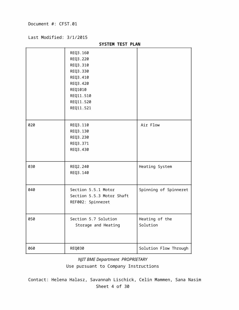
1. Wooden Encasement2. Plexiglas Lid3. Floor Insulation4. Wall Insulation5. Air Compressor Tube Attachment6. Ventilation Holes7. Two-Sided Buffer System8. Fume Hood and Fume Hood Exhaust Attachment9. Spinneret10. Motor and Housing11. Speed Controller12. Solution Storage and Heating13. Peristaltic Pump14. Upper Tubing15. Lower Tubing16. Collection Screen17. Linear Actuator18. Stabilization Posts of Linear Actuator19. Collection Screen Attachment20. Thermometer
NJIT BME Department PROPRIETARYUse pursuant to Company Instructions
Contact: Helena Halasz, Savannah Lischick, Celin Mammen, Sana Nasim Sheet 4 of 30

Document #: CFST.01 Last Modified: 3/1/2015
SYSTEM TEST PLAN
5. DEFINITIONS REFXXX: Refer to requirement in Capstone Spring 2014 Team 3 High Level Requirements Document.
REQXXX: Refer to requirement in Capstone Spring 2015 Team 8 High Level Requirements Document (CFSFR.01).
6. SETUPThis testing requires the following units as a minimum: A Centrifugal Force Spinner, Masterflex Peristaltic Pump, Bronco 50064 Air Compressor, and Fume Hood Exhaust.
7. EQUIPMENT RECORDThe following test equipment, or equivalent, is needed to execute the tests in this plan.
Item Model Number(s) Calibration Required?
Tape Measure N/A No
Digital Caliper N/A Yes (Zeroed)
Airflow Velocity Meter N/A Yes
Thermometer (Celsius) N/A No
Tachometer N/A No
Peristaltic Pump Cole Parmer #7518-00 No
Hot Plate LABRepCo H3760 Series Digital Hotplate
No
Fume Hood Exhaust N/A No
Air Compressor Bronco 50064 No
Heater Staco Energy Products Co. No
Linear Actuator gearWORKS AC Motor: Johnson Metal Industries CO.
No
NJIT BME Department PROPRIETARYUse pursuant to Company Instructions
Contact: Helena Halasz, Savannah Lischick, Celin Mammen, Sana Nasim Sheet 5 of 30

Document #: CFST.01 Last Modified: 3/1/2015
SYSTEM TEST PLAN
8. TEST CASES
[Test Case 010] Physical Measurements
Purpose: To verify correct dimensions are used in the Centrifugal Force Spinner as specified by CFSFR.01. Specification:
REQ2.210REQ3.210REQ3.160REQ3.220REQ3.310REQ3.330REQ3.410REQ3.420REQ1010REQ11.510 REQ11.520REQ11.521
Test Architecture:
Figure 2. Directions on how to measuring using tape measure (1) and the outside (2) and the inside (3) tongs of the caliper.
NJIT BME Department PROPRIETARYUse pursuant to Company Instructions
Contact: Helena Halasz, Savannah Lischick, Celin Mammen, Sana Nasim Sheet 6 of 30
Document #: CFST.01 Last Modified: 3/1/2015
SYSTEM TEST PLAN
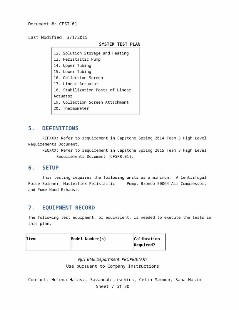
Figure 3: Size and placement of Ventilation Holes.Equipment:
1. Tape Measure (Imperial Units)2. Digital Caliper (Imperial Units)
Test Procedure: 1. For dimensions greater than 10 inches, use a Tape Measure; for less than or equal to 10 inches use a digital caliper
as there is greater accuracy in a caliper, but they are limited in their ability to measure large distances.2. Measure the specified distance based on the requirement.
a. Using a tape measure: (shown in Figure 2, #1)i. Put one end of the tape measure on the end of the portion being measured.
ii. Pull the tape to the other end of the portion being measured.iii. Mark the part where the edge of the item being measures lines up with the increments on the tape
measure.NJIT BME Department PROPRIETARYUse pursuant to Company Instructions
Contact: Helena Halasz, Savannah Lischick, Celin Mammen, Sana Nasim Sheet 7 of 30

Document #: CFST.01 Last Modified: 3/1/2015
SYSTEM TEST PLAN b. Using a Digital Caliper
i. Turn unit on.ii. Using the outside caliper, put the portion being measured between the caliper legs (seen in Figure
2, #2).1. Compress the legs firmly until they are enclosed around the portion being measured.
iii. Using the inside caliper, put the legs into the portion being measured.iv. Extend the legs until they touch the portion being measured (seen in Figure 2, #3).
Expected Results Test passes if all of the following occurs:1. Measurements are within specified tolerances as described in Test Results Table of Test Case 010 Physical
Measurements.
Test Results:
Item Expected Result Test Result: Pass/Fail
Polystyrene Insulation
Side dimensions with tolerances of ± 0.5 inch A: 19 x 31 inch B: 19 x 34 inch C: 19 x 31 inch D: 19 x 34 inchThickness 1 ± 0.05 inch
Side dimensions A: B: C: D:Thickness A:
B: C: D:
Ventilation Holes Refer to figure 3 DiameterHole 1: 2: 3: 4:PlacementHole 1: 2: 3: 4:
Buffer System Buffer size (length x width) with tolerances of ± 0.5 inch 1: 34 x 21 inch 2: 34 x 21 inch Buffer placement from wall
Buffer size 1: 2:Buffer placement from wall 1:
NJIT BME Department PROPRIETARYUse pursuant to Company Instructions
Contact: Helena Halasz, Savannah Lischick, Celin Mammen, Sana Nasim Sheet 8 of 30

Document #: CFST.01 Last Modified: 3/1/2015
SYSTEM TEST PLAN
1: 3 ± 0.5 inch from wall B 2: 3 ± 0.5 inch from wall C
2:
Collection screen Diameter: Minimum: 15 ± 0.5 inch Maximum: 40 ± 0.5 inchHeight: 8 ± 0.2 inch
Diameter: Minimum: Maximum:Height:
Fume Hood Attachment Hole
Diameter: 8 ± 0.1 inchPlacement: 15.5 ± 0.2 inch
Diameter:Placement:
Air Compressor Hole
Diameter: 0.5 ± 0.1 inchPlacement: 4.5 ± 0.2 inch
Diameter:Placement:
Linear Actuator Platform
Length: 15 ± 0.1 inchesWidth: ¾ ± 0.1 inchDepth: 2 ± 0.1 inchVertical Holes: Diameter: ½ ± 0.01 inch Placement: Figure 3Horizontal holes
Diameter ⅛ ± .01 inchPlacement: Figure 3
Length: WidthDepthVertical Holes: Diameter: Placement: Horizontal holes
Diameter Placement:
NJIT BME Department PROPRIETARYUse pursuant to Company Instructions
Contact: Helena Halasz, Savannah Lischick, Celin Mammen, Sana Nasim Sheet 9 of 30

Document #: CFST.01 Last Modified: 3/1/2015
SYSTEM TEST PLAN
[Test Case 020] Airflow
Purpose: To verify the airflow produced by the air compressor, vents, and fume hood exhaust is correct as specified by CFSFR.01. Specification:
REQ3.110REQ3.130REQ3.230REQ3.371REQ3.430
Test Architecture:
Equipment:
1. Air Flow Velocity Meter
NJIT BME Department PROPRIETARYUse pursuant to Company Instructions
Contact: Helena Halasz, Savannah Lischick, Celin Mammen, Sana Nasim Sheet 10 of 30
Document #: CFST.01 Last Modified: 3/1/2015
SYSTEM TEST PLAN
NJIT BME Department PROPRIETARYUse pursuant to Company Instructions
Contact: Helena Halasz, Savannah Lischick, Celin Mammen, Sana Nasim Sheet 11 of 30

Document #: CFST.01 Last Modified: 3/1/2015
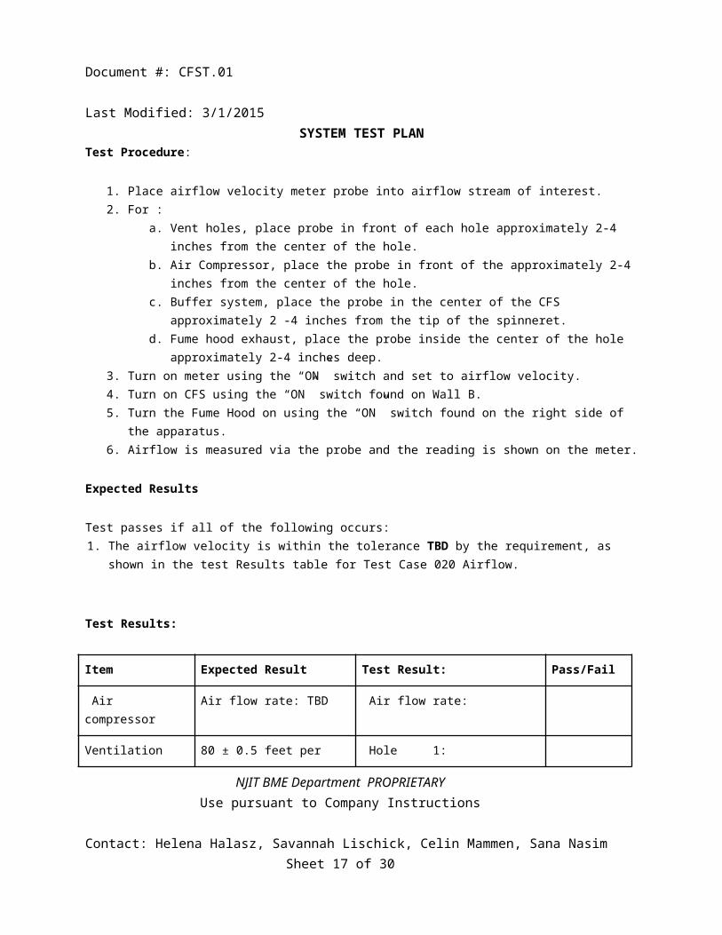
SYSTEM TEST PLAN Test Procedure:
1. Place airflow velocity meter probe into airflow stream of interest.2. For :
a. Vent holes, place probe in front of each hole approximately 2-4 inches from the center of the hole. b. Air Compressor, place the probe in front of the approximately 2-4 inches from the center of the
hole. c. Buffer system, place the probe in the center of the CFS approximately 2 -4 inches from the tip of
the spinneret.d. Fume hood exhaust, place the probe inside the center of the hole approximately 2-4 inches deep.
3. Turn on meter using the “ON” switch and set to airflow velocity.4. Turn on CFS using the “ON” switch found on Wall B.5. Turn the Fume Hood on using the “ON” switch found on the right side of the apparatus.6. Airflow is measured via the probe and the reading is shown on the meter.
Expected Results Test passes if all of the following occurs:1. The airflow velocity is within the tolerance TBD by the requirement, as shown in the test Results table for Test
Case 020 Airflow. Test Results:
Item Expected Result Test Result: Pass/Fail
Air compressor Air flow rate: TBD Air flow rate:
Ventilation holes 80 ± 0.5 feet per minute Hole 1: 2: 3: 4:
Buffer System 20 ± 0.1 feet per minute Air flow rate:
Fume Hood Exhaust 80 ± 0.1 feet per minute Air flow rate:
NJIT BME Department PROPRIETARYUse pursuant to Company Instructions
Contact: Helena Halasz, Savannah Lischick, Celin Mammen, Sana Nasim Sheet 12 of 30

Document #: CFST.01 Last Modified: 3/1/2015
SYSTEM TEST PLAN
[Test Case 030] Heating System
Purpose: To verify that the heating mechanism functions to heat the encasement as specified by CFSFR.01. Specification:
REQ2.240REQ3.140
Test Architecture:
Figure 6: Diagram demonstrating the use of a thermometer in the device.
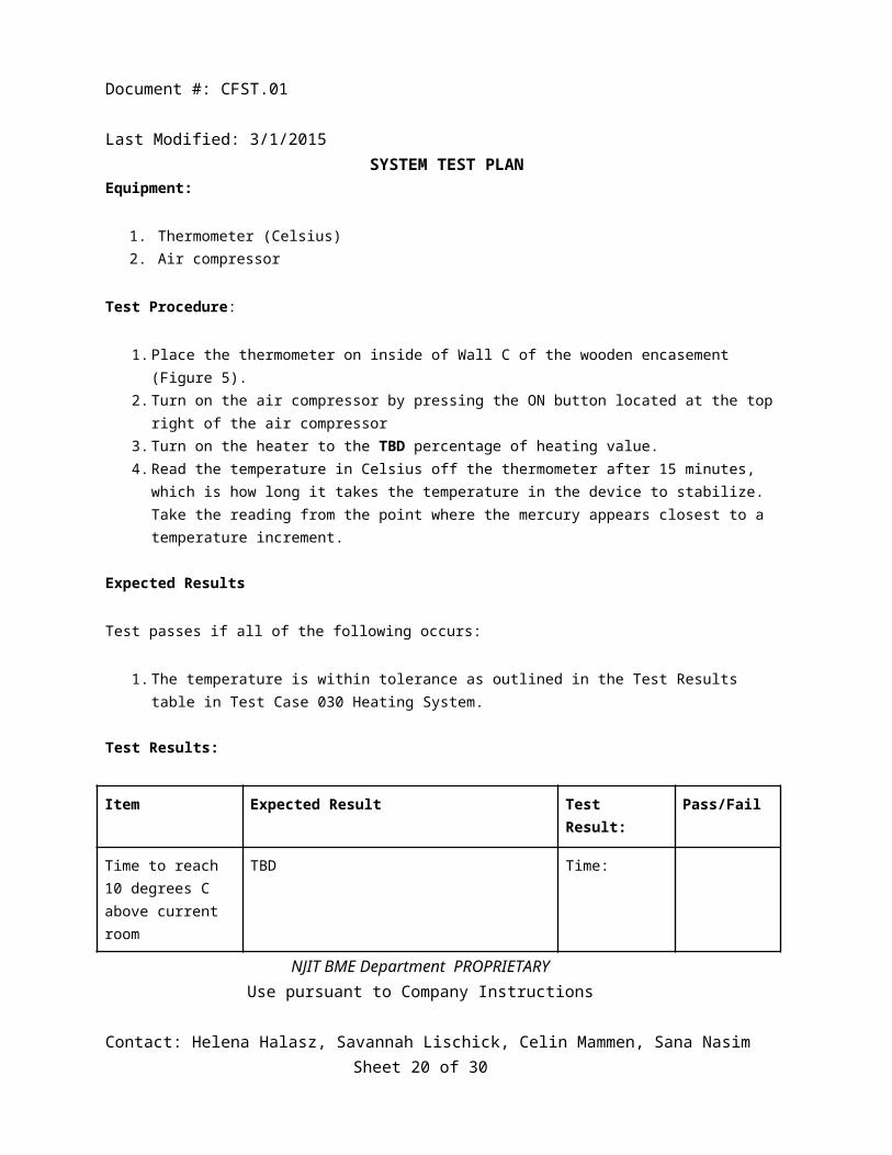
Equipment:
1. Thermometer (Celsius)2. Air compressor
Test Procedure:
1. Place the thermometer on inside of Wall C of the wooden encasement (Figure 5).
NJIT BME Department PROPRIETARYUse pursuant to Company Instructions
Contact: Helena Halasz, Savannah Lischick, Celin Mammen, Sana Nasim Sheet 13 of 30

Document #: CFST.01 Last Modified: 3/1/2015
SYSTEM TEST PLAN 2. Turn on the air compressor by pressing the ON button located at the top right of the air compressor3. Turn on the heater to the TBD percentage of heating value.4. Read the temperature in Celsius off the thermometer after 15 minutes, which is how long it takes the
temperature in the device to stabilize. Take the reading from the point where the mercury appears closest to a temperature increment.
Expected Results Test passes if all of the following occurs:
1. The temperature is within tolerance as outlined in the Test Results table in Test Case 030 Heating System.
Test Results:
Item Expected Result Test Result: Pass/Fail
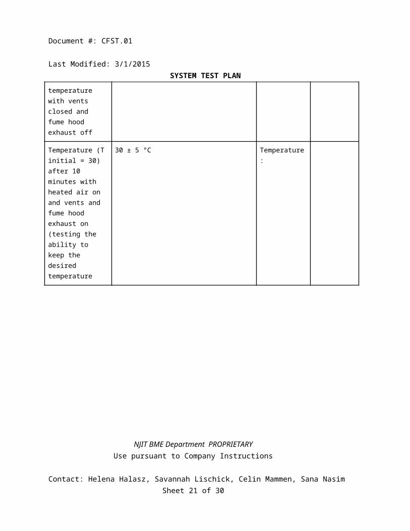
Time to reach 10 degrees C above current room temperature with vents closed and fume hood exhaust off
TBD Time:
Temperature (T initial = 30) after 10 minutes with heated air on and vents and fume hood exhaust on(testing the ability to keep the desired temperature
30 ± 5 °C Temperature:
NJIT BME Department PROPRIETARYUse pursuant to Company Instructions
Contact: Helena Halasz, Savannah Lischick, Celin Mammen, Sana Nasim Sheet 14 of 30

Document #: CFST.01 Last Modified: 3/1/2015
SYSTEM TEST PLAN
[Test Case 040] Spinning of the Spinneret
Purpose: To verify that the Spinneret and Mount Shaft are controlled by the motor that is spinning between 10,000RPM – 20,000RPM, as specified in CFSFR.01. Specification:
Section 5.5.1 MotorSection 5.5.3 Motor ShaftREF002: Spinneret
Test Architecture:
Figure 7: Diagram demonstrating the use of a thermometer in the device.
Equipment:
1. Tachometer2. Spinneret and Mount Shaft connection secured3. Spinneret and Mount Shaft connection to motor
NJIT BME Department PROPRIETARYUse pursuant to Company Instructions
Contact: Helena Halasz, Savannah Lischick, Celin Mammen, Sana Nasim Sheet 15 of 30

Document #: CFST.01 Last Modified: 3/1/2015
SYSTEM TEST PLAN Test Procedure:
1. Securely attach the spinneret to the mount shaft structure by tightening the set screws in the lower part of the spinneret head.
a. Use a number 3 Standard Phillips Screwdriver.2. Place the Plexiglas lid back again.3. Turn on the device by using the “ON” switch on Wall B.4. Initiate the Tachometer by plugging into a 110V wall socket.5. Hold the tachometer outside Plexiglas lid and perpendicularly point the tachometer at the spinneret head as
shown in test architecture.6. Read the readings on the LCD of the tachometer as the spinneret moves..
Expected Results Test passes if all of the following occurs:
1. The tachometer reading is within the tolerance as outlined in the Test Results table in Test Case 030 Heating System.
Test Results:
Trial Expected Result Test Result: Pass/Fail
Spinneret (RPM) 10,000RPM
15,000RPM
20,000RPM
NJIT BME Department PROPRIETARYUse pursuant to Company Instructions
Contact: Helena Halasz, Savannah Lischick, Celin Mammen, Sana Nasim Sheet 16 of 30
Document #: CFST.01 Last Modified: 3/1/2015
SYSTEM TEST PLAN
[Test Case 050] Heating of the Solution
Purpose: To verify the heating of the solution is correct as specified by CFSFR.01. Specification:
Section 5.7 Solution Storage and Heating Test Architecture:
Figure 8: Diagram demonstrating the use of a thermometer in the device.
Equipment:
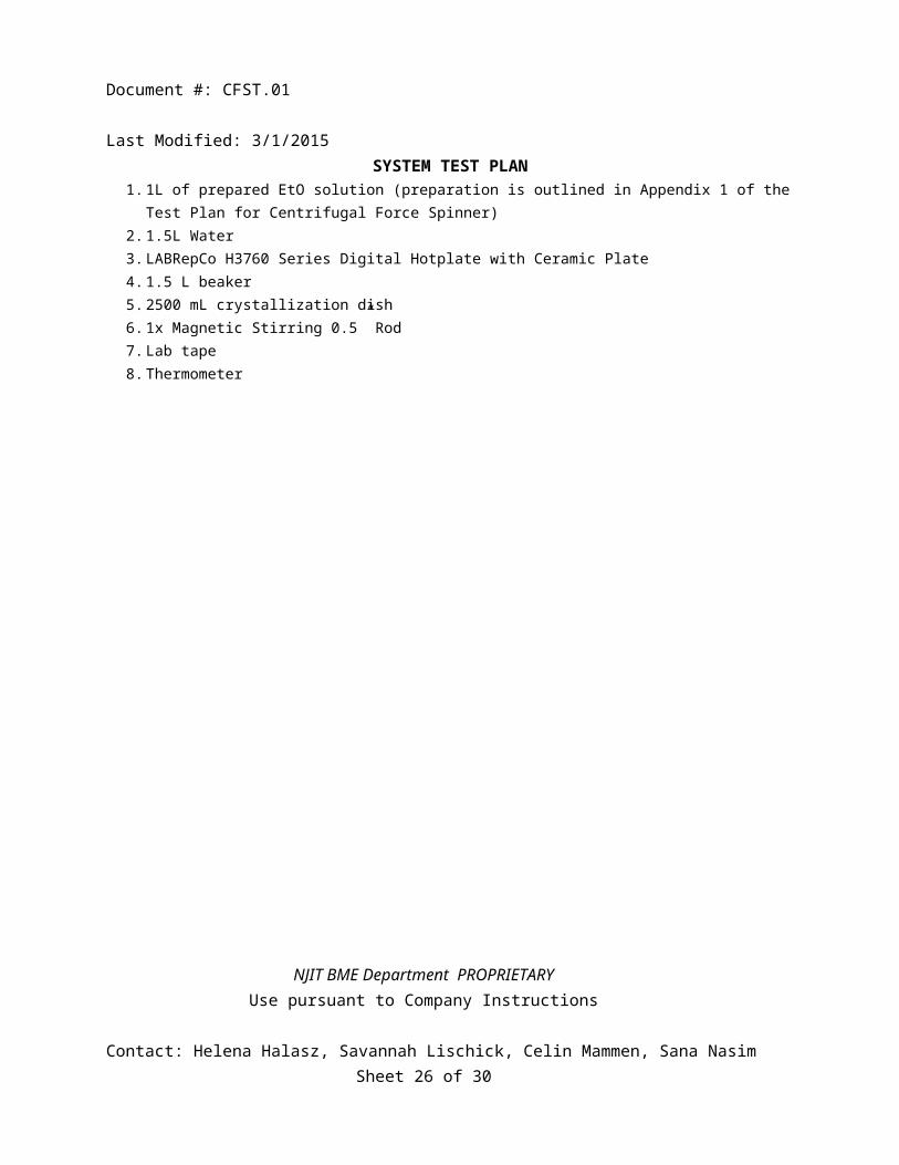
1. 1L of prepared EtO solution (preparation is outlined in Appendix 1 of the Test Plan for Centrifugal Force Spinner)
2. 1.5L Water3. LABRepCo H3760 Series Digital Hotplate with Ceramic Plate4. 1.5 L beaker5. 2500 mL crystallization dish6. 1x Magnetic Stirring 0.5” Rod7. Lab tape8. Thermometer
NJIT BME Department PROPRIETARYUse pursuant to Company Instructions
Contact: Helena Halasz, Savannah Lischick, Celin Mammen, Sana Nasim Sheet 17 of 30

Document #: CFST.01 Last Modified: 3/1/2015
SYSTEM TEST PLAN
NJIT BME Department PROPRIETARYUse pursuant to Company Instructions
Contact: Helena Halasz, Savannah Lischick, Celin Mammen, Sana Nasim Sheet 18 of 30

Document #: CFST.01 Last Modified: 3/1/2015
SYSTEM TEST PLAN Test Procedure:
1. Pour the 1L of EtO solution in the 1.5 L container.2. Take a crystalline dish and fill it with ¾ of water (a little more than a liter).3. Place the crystalline dish filled with water on the hot plate.4. Place the beaker with the solution in the water.5. Turn the temperature and the stirring to 50°C.6. Set stirring to 5 RPM.7. Wait 30 minutes to allow the solution to mix completely.8. Insert thermometer. Record data.
Expected Results Test passes if all of the following occurs:
1. The reading of the thermometer is consistent with the temperature setting on the hot plate. Test Results:
Item Expected Result Test Result: Pass/Fail
°C of reading on hotplate
Equivalent to hotplate reading Temperature:
NJIT BME Department PROPRIETARYUse pursuant to Company Instructions
Contact: Helena Halasz, Savannah Lischick, Celin Mammen, Sana Nasim Sheet 19 of 30
Document #: CFST.01 Last Modified: 3/1/2015
SYSTEM TEST PLAN
[Test Case 060] Solution Flow Through Entire System
Purpose: To verify that the Peristaltic Pump can successfully pump 1L of EtO solution through the upper and lower tubing, as outlined in CFSFR.01. Specification:
REQ030 Section 5.3: Peristaltic Pump Section 5.9: Tubing Test Architecture:
Figure 9: This figure shows the overall setup of the peristaltic pump to the tubing system. For the purposes of this
test, the lower tubing will be placed in an empty beaker, as seen in Figure 11.
NJIT BME Department PROPRIETARYUse pursuant to Company Instructions
Contact: Helena Halasz, Savannah Lischick, Celin Mammen, Sana Nasim Sheet 20 of 30
Document #: CFST.01 Last Modified: 3/1/2015
SYSTEM TEST PLAN
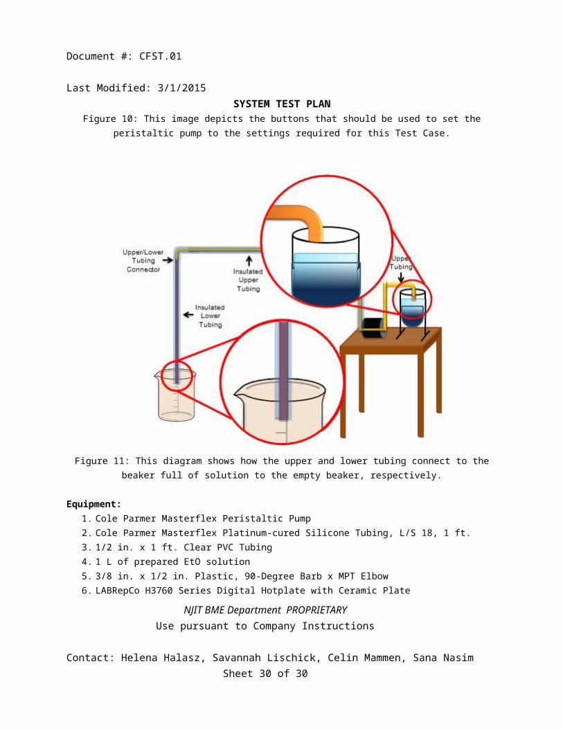
Figure 10: This image depicts the buttons that should be used to set the peristaltic pump to the settings required for this Test Case.
NJIT BME Department PROPRIETARYUse pursuant to Company Instructions
Contact: Helena Halasz, Savannah Lischick, Celin Mammen, Sana Nasim Sheet 21 of 30

Document #: CFST.01 Last Modified: 3/1/2015
SYSTEM TEST PLAN
Figure 11: This diagram shows how the upper and lower tubing connect to the beaker full of solution to the empty beaker, respectively.
Equipment:1. Cole Parmer Masterflex Peristaltic Pump2. Cole Parmer Masterflex Platinum-cured Silicone Tubing, L/S 18, 1 ft.3. 1/2 in. x 1 ft. Clear PVC Tubing4. 1 L of prepared EtO solution5. 3/8 in. x 1/2 in. Plastic, 90-Degree Barb x MPT Elbow6. LABRepCo H3760 Series Digital Hotplate with Ceramic Plate7. 2 x 1.5 L beaker8. 2500 mL crystallization dish9. 1x Magnetic Stirring 3” Rod10. Lab tape11. 1.5L water12. Timer
NJIT BME Department PROPRIETARYUse pursuant to Company Instructions
Contact: Helena Halasz, Savannah Lischick, Celin Mammen, Sana Nasim Sheet 22 of 30

Document #: CFST.01 Last Modified: 3/1/2015
SYSTEM TEST PLAN Test Procedure:1. Plug peristaltic pump into 110 V wall socket.2. Turn peristaltic pump on by pressing the power button. 3. Set tube size on machine to L/S-18 by pressing “ size” button until “18” lights up. See Figure 11. 4. Lift pumphead lever to open pumphead.5. Insert Masterflex silicone tube laterally.6. Close pumphead lever to secure tube.7. Insert one end of the tube into solution; secure into place by lab tape.8. Insert the other end of the silicone tube into the 90-degree elbow connector.9. Into the second end of the elbow connector, insert the1/2in clear PVC tubing.10. Insert the other end of the PVC tubing into the second, empty 1.5 L beaker.11. Secure tube to beaker using lab tape.12. As “Start” button is pressed, begin timing simultaneously.13. Wait until the beaker on the hot plate is emptied into the second, initially empty beaker.14. Stop timer when that occurs; simultaneously press blue “Stop” button on peristaltic pump.
Expected Results Test passes if all of the following occurs: 1. If the output rate at the end of the lower tubing to the spinneret head is < 10mL/minute.2. If there is less than 5mL of leakage.
Test Results:
Item Expected Results Test Result: Pass/Fail
Flowrate (mL/min) < 10mL/ minute Flowrate:
Leakage from connector
>5mL mL:
NJIT BME Department PROPRIETARYUse pursuant to Company Instructions
Contact: Helena Halasz, Savannah Lischick, Celin Mammen, Sana Nasim Sheet 23 of 30

Document #: CFST.01 Last Modified: 3/1/2015
SYSTEM TEST PLAN
[Test Case 070] Circuitry
Purpose: To verify that the linear actuator circuitry works to perform its intended task: move the platform up and down, as specified in CFSFR.01. Specification:
5.11 Linear Actuator Test Architecture: TEST TBD UNTIL CIRCUIT IS FINALIZED Equipment:
1. Multimeter2. Linear Actuator
Test Procedure:
1. Plug into wall socket.2. Identify wires across Relay 1.3. Turn on multimeter to 10 amps current. Place test leads of multimeter across Relay 1.4. Remove test leads and flip switch to “ON” position.5. Check current across Relay 1 again. 6. Switch multimeter to voltage. Place probes on potentiometer from the motor.7. Visually inspect motor for vertical actuation.
Expected Results Test passes if all of the following occurs:
1. The current across Relay 1 is 0 milliamps when the switch is “OFF”.2. The current across Relay 1 is TBD when the switch is “ON”.3. The voltage across the potentiometer increases from .66 volts to 4.9 volts as the actuator moves downward.4. The voltage across the potentiometer decreases from 4.9 volts to .66 volts as the actuator moves upward.
Test Results:
Item Expected Results Test Result: Pass/Fail
Current across Relay 1 (“OFF”)
0 milliamps
NJIT BME Department PROPRIETARYUse pursuant to Company Instructions
Contact: Helena Halasz, Savannah Lischick, Celin Mammen, Sana Nasim Sheet 24 of 30

Document #: CFST.01 Last Modified: 3/1/2015
SYSTEM TEST PLAN
Current across Relay 1(“ON”)
TBD milliamps
Voltage rage when actuator moves up
decreases from 4.9 volts to .66 volts
Voltage rage when actuator moves down
increases from .66 volts to 4.9 volts
NJIT BME Department PROPRIETARYUse pursuant to Company Instructions
Contact: Helena Halasz, Savannah Lischick, Celin Mammen, Sana Nasim Sheet 25 of 30
4cm
Document #: CFST.01 Last Modified: 3/1/2015
SYSTEM TEST PLAN
[Test Case 080] Linear Actuator
Purpose: To verify that the platform and collection screen attached to the linear actuator move vertically, as specified in CFSFR.01. Specification: Section 5.11: Linear Actuator Test Architecture:
Figure 12: Diagram showing the side view of the linear actuator platform as it connects to the collection screen. The screen moves vertically when the platform moves up and down and can be visually inspected.
Equipment:1. Centrifugal Force Spinner2. Timer
NJIT BME Department PROPRIETARYUse pursuant to Company Instructions
Contact: Helena Halasz, Savannah Lischick, Celin Mammen, Sana Nasim Sheet 26 of 30

Document #: CFST.01 Last Modified: 3/1/2015
SYSTEM TEST PLAN 3. Tape Measure
Figure 13: Top view of linear actuator and collection screen subsystem.
Test Procedure:
1. Mark the position of the platform as it appears on the tape measure.2. Turn the linear actuator on by pressing the “ON” button, located on Wall B. See Figure 1: Overall CFS
Device. 3. Simultaneously press “Start” on the timer.4. As the linear actuator platform moves up, time its movement. Turn the device “OFF” when it reaches the
top; simultaneously hit “Stop” on the timer.5. Record the results.
Expected Results Test passes if all of the following occurs:
1. The linear actuator platform moves a total of 4 ± 0.5 inches vertically.2. If the linear actuator speed moves with a velocity of TBD inches/min or less.
Test Results:
Item Test Result: Pass/Fail
Velocity (inches/min) 1in/min
NJIT BME Department PROPRIETARYUse pursuant to Company Instructions
Contact: Helena Halasz, Savannah Lischick, Celin Mammen, Sana Nasim Sheet 27 of 30

Document #: CFST.01 Last Modified: 3/1/2015
SYSTEM TEST PLAN
Total Distance (inches)
4 ± 0.5 inches
[Test Case 090] Whole System Test: Spinning EtO using the Centrifugal Force Spinner
Purpose: To verify that the CFS device performs all functions together, as specified in CFSFR.01, and outputs nanofibers when spun at a rate between 10-20,000RPM. This is assuming all subsystem tests were successful. Specification: REQ020
REQ030 Test Architecture:
Figure 14: Diagram shows how a glass slide can be used to scrape the white nanofibers of the collection screen.
Equipment:
1. Centrifugal Force Spinner2. 1 L of EtO solution3. Lab glass slide
Test Procedure:
1. TBD Expected Results
NJIT BME Department PROPRIETARYUse pursuant to Company Instructions
Contact: Helena Halasz, Savannah Lischick, Celin Mammen, Sana Nasim Sheet 28 of 30

Document #: CFST.01 Last Modified: 3/1/2015
SYSTEM TEST PLAN Test passes if all of the following occurs:
1. The linear actuator moves the collection screen continuously up and down.2. The spinneret head spins 1L of EtO solution into nanofibers that spew onto the moving collection screen.3. Nanofibers can be scraped off screen using a glass slide. See Figure 14 above.
Test Results:
Item Test Result: Pass/Fail
Ability to scrape nanofibers onto glass slide[Visual check]
Movement of the linear actuator[Visual check]
NJIT BME Department PROPRIETARYUse pursuant to Company Instructions
Contact: Helena Halasz, Savannah Lischick, Celin Mammen, Sana Nasim Sheet 29 of 30
Document #: CFST.01 Last Modified: 3/1/2015
SYSTEM TEST PLAN
9. APPENDIX
A. Etheleyne Oxide (EtO) Solution PreparationEquipment:
1. Electronic Lab Magnetic Mixer with Speed and Temperature Control2. (1= slowest rotating speed/lowest temperature setting, 5 = fastest rotating3. speed/highest temperature setting)4. Electronic Lab Scale5. EtO Powder with molecular weight of 1,000,0006. De-ionized Water in squirt bottle7. 10 ml graduated cylinder8. 500 ml beaker9. 0.5 inch magnetic stirrer10. 20 ml disposable storage bottles11. Straw scooper12. Safety goggles and latex gloves13. Labeling tape14. Paper towels
Test Procedure:1. Take a small piece of labeling tape and use it to cover the 20 ml bottles.2. Make sure to label your 20ml bottles according to the following format below:3. Obtain the water needed for spinning:4. For weight/volume solution, measure 10mL of DI water using the squirt bottle, measure 10 ml
in the graduated cylinder and pour it into the 20 ml bottle.5. For a weight/weight solution place the 20 mL bottle onto the Electronic Scale, tare the weight to
remove the bottle weight factor, and measure 10g of water by using the squirt bottle6. To make 10% EtO measure 1.33 g of EtO using the straw scooper to pick up and transfer the
powder into the 20ml bottle.7. Place the magnetic stirrer in the 20 ml bottle.8. Place bottle within the water bath9. Place the 500ml beaker onto the magnetic stirrer with temperature control10. Turn on the stirring control to 7 and temperatures 50 degree Celsius, an acceptable temperature
range to heat the solution to dissolve.11. Leave the 20 ml bottles on stirrer until a homogeneous solution forms in approximately over
night.
NJIT BME Department PROPRIETARYUse pursuant to Company Instructions
Contact: Helena Halasz, Savannah Lischick, Celin Mammen, Sana Nasim Sheet 30 of 30

Document #: CFST.01 Last Modified: 3/1/2015
SYSTEM TEST PLAN
10. ATTACHMENTSCover Sheet for QUALITY RECORDS
Test Plan Name
Test Engineer
Test Date
Version (HW) (SW)
System Name
Tests covered
MRs written? Yes or No [see next page]
Data Attached? Yes or No
Old Results appended? Yes or No
Record Type System Test Results
Date Filed
Storage Location (Room #)
Approval Signature(s)
NJIT BME Department PROPRIETARYUse pursuant to Company Instructions
Contact: Helena Halasz, Savannah Lischick, Celin Mammen, Sana Nasim Sheet 31 of 30

Document #: CFST.01 Last Modified: 3/1/2015
SYSTEM TEST PLAN TEST STATUS
Test Case
TEST PASSED?
IT TEST FAILED
MR#
IF TEST FAILED, MR NOT
ENTEREDREASON
COMMENT
END OF DOCUMENT
NJIT BME Department PROPRIETARYUse pursuant to Company Instructions
Contact: Helena Halasz, Savannah Lischick, Celin Mammen, Sana Nasim Sheet 32 of 30