Embed Size (px)
Citation preview

4.1.4Contr A35-Section VI SOW-substation May 2014 KPLC
SCOPE OF WORK - SUBSTATION

VI - i
4.1.4Contr A35-Section VI SOW-substation May 2014 KPLC
TABLE OF CONTENTS
4.2 SCOPE OF WORK - SUBSTATIONS .......................................................................................... 1
4.2.1 General ................................................................................................................................ 1 4.2.2 Standard Substation ............................................................................................................... 2 4.2.3 33 kV Switchgear GIS Type ..................................................................................................... 2
4.2.3.1 Transformer Bay ......................................................................................................................... 2 4.2.3.2 Feeder Bay ................................................................................................................................ 3 4.2.3.3 33kv Bus Bar Protection ........................................................................................................... 3
4.2.5 Auxiliary transformer for 33/11kV Substation ............................. Error! Bookmark not defined. 4.2.6 MV Power Cables from Transformer to Indoor Switchgear ........... Error! Bookmark not defined. 4.2.7 MV Power Cables from Indoor Switchgear to line termination tower ........... Error! Bookmark not defined. 4.2.8 Control, Protection, Metering and Signalling............................................................................ 5
4.2.8.1 Substation Automation System ..................................................................................................... 5 4.2.8.2 Control and Measuring Cables ...................................................................................................... 7 4.2.8.3 Telecommunications ................................................................................................................... 7
4.2.9 Auxiliary AC Supply Equipment .............................................................................................. 9 4.2.9.1 Main AC Distribution Board ........................................................................................................ 9 4.2.9.2 Sub-distribution Boards and Panels ............................................................................................... 9 4.2.9.3 Cables ....................................................................................................................................... 9
4.2.10 DC Supply System .............................................................................................................. 9 4.2.10.1 Battery ...................................................................................................................................... 9 4.2.10.2 Charger ..................................................................................................................................... 9 4.2.10.3 Switchboard ............................................................................................................................. 10 4.2.10.4 Battery Conductors and Fuses ..................................................................................................... 10 4.2.10.5 Sub-distribution Boards and Panels ............................................................................................. 10 4.2.10.6 Cables ..................................................................................................................................... 10
4.2.11 Earthing System .............................................................................................................. 10 4.2.12 Ancillary Equipment ........................................................................................................ 11
4.2.12.1 Station Equipment .................................................................................................................... 11 4.2.12.2 Earthing Devices ...................................................................................................................... 11 4.2.12.3 Cable Accessories ..................................................................................................................... 11 4.2.12.4 Racks, Conduits, Ducts, etc ........................................................................................................ 11
4.2.13 Power transformers .............................................................. Error! Bookmark not defined. 4.2.13.1 Type of transformers ..................................................................... Error! Bookmark not defined. 4.2.13.2 CTs for Power Transformers .......................................................... Error! Bookmark not defined.
4.2.14 Civil Works ..................................................................................................................... 11 4.2.14.1 Platform works ............................................................................. Error! Bookmark not defined. 4.2.14.2 Switchgear buildings ................................................................................................................. 11 4.2.14.3 Transformer foundations ................................................................ Error! Bookmark not defined. 4.2.14.4 Cable Trenches ........................................................................................................................ 11
4.2.15 Training in control (SAS), Telecommunication and protection system .................................... 11 4.2.16 Factory Acceptance Test................................................................................................... 12 4.2.17 Test Equipment (TS –001) ................................................................................................. 12 4.2.18 Final documentation ........................................................................................................ 12 4.2.19 Site Offices and site facilities(LS-010, -011) ....................................................................... 12 4.2.20 KIPEVU ............................................................................. Error! Bookmark not defined. 4.2.21 Mandatory Spare Parts and Tools ...................................................................................... 13
4.2.21.1 For Transformers ...................................................................................................................... 14 4.2.21.2 For Substations ........................................................................................................................ 14
4.2.22 Recommended Spare Parts and Tools ................................................................................. 14

Kenya Power and Lighting Company VI 4.2 - 1 Contract A35
KENYA POWER Funded Project Technical Specifications and Drawings
4.1.4Contr A35-Section VI SOW-substation May 2014 KPLC
4.2 SCOPE OF WORK - SUBSTATIONS
4.2.1 General
The Bidder shall examine the scope of works in this section in close connection with the other
documents and particulars forming these Bidding Documents.
Special attention shall be paid to General Specifications and Particular Technical
Specifications, in which the general technical requirements are specified. The drawings
enclosed in are for bidding purposes only.
If the Specifications and/or Drawings do not contain particulars of materials or goods, which
are necessary for the proper and safe completion, operation, and maintenance of the
equipment in question, all such materials shall be deemed to be included in the supply.
In the event of any conflict between the Drawings and the Specifications, the latter shall
prevail.
In the event of any conflict between scaled dimensions and figures on the Drawings, the
figures shall prevail.
Should the Bidder find discrepancies in or omissions from these Specifications or from the
other Documents, or should he be in doubt as to their meaning, he should immediately contact
the Project Manager for interpretation, clarification or correction thereof before submitting his
Bid. Such action shall, however, in no case be considered as a cause for altering the closing
date of the Bid.
The scope of work for equipment shall cover engineering design, manufacture, testing before
shipment and packing sea worthy or otherwise as required, delivery CIP site, of all equipment
as specified in the preceding chapters.
For substations contracted on turnkey basis the substation contractor shall be responsible for
design, material supply, transport, erection, and installation and commissioning as well as
having the full responsibility for civil works including design and construction of transformer
foundations and control building.
The Contractor shall install double bus bar gas insulated with the following bays feeders,
incomers and a bus coupler. The contractor shall interface the 33kV switch gear to the
existing 132/33 kV transformers and 33/11kv transformers.
The existing 33kV feeders interface connections, support structures shall be designed by the
contractor and approved by the project manager. The design shall meet the requirements for
highly saline environment and shall minimize outages for interface.
The existing building shall be used for the switch gear and its recommended that the
contractor shall familiarize himself with all the building design and status and carry out
necessary modifications and reinforcement.
Loose equipment for the Employer’s rehabilitation shall be complete with documentation and
ancillaries like programs, licences and programming tools.

Kenya Power and Lighting Company VI 4.2 - 2 Contract A35
KENYA POWER Funded Project Technical Specifications and Drawings
4.1.4Contr A35-Section VI SOW-substation May 2014 KPLC
Equipment that is to be dismantled and removed from existing substations is to be recovered
by the Contractor and deposited to sites within or in the immediate vicinity of each substation.
Such sites are to be designated by the Employer. The recovered equipment is to be taken over
by the Employer at these sites.
KPLC has a SCADA (Supervisory, Control & Data Acquisition) system that is controlled
from the Regional Control Centres& the National Control Centre. The National Control
Centre (NCC) is at Juja Rd and controls the entire transmission network & substations (ie
some 66kV, all 132kV, all 220kV & soon to be introduced 400kV stations.)
There are 4 regional control centres in total. These are located in the following locations; Juja
Rd (Nairobi region), Rabai (Coast region), Lessos (West Kenya region) & Kiganjo (Mt
Kenya region). These Regional Control Centres monitor & control the 11KV, 33kV & 66kV
Distribution networks &substations in their specific regions.
The Control Centres all run ABB’s Network Manager WS500 which is the software used for
monitoring & Control of all the incorporated substations. The Communication protocol
currently supported by KPLCs front end servers is ABBs PCU 400, for data telegram
exchange with Remote Terminal Units (RTUs). Whereas, the Station Control Management
Systems (SCMS) in the substations in its SCADA system are IEC 60870-5-101&IEC
60870-5-104.
The automated 33kV Distribution substation will be required to communicate with the front
end server (ABB’s PCU400) via communication protocols outlined above. The automated
sub-Station must communicate with the Regional Control Centre under which it shall be
monitored & controlled.
The interconnected KPLC’s telecommunications system is based on a backbone of SDH
STM1/4 terminal equipment, FOX 515 from ABB. A network management system (NMS)
for the telecommunication system has been installed at NCC.
4.2.2 Standard Substation
This section defines the standard substation components.
4.2.3 33 kV Switchgear GIS Type
4.2.3.1 33kV incomer Bay
1 (one) complete bay shall be equipped with:
a. 1 (one) set of GIS for 33kV incomer bay with circuit breaker, disconnectors,
earthing switch, fast acting earthing switch, current transformers, 3 phase voltage
transformers, busbars and busbars connections. Outdoor bushings, transition bus and
surge diverters.
b. 1 (one) set of control/protection panel
c. 1 (one) bay control unit with proper display, for measurements (V,I,MVAR,MW)
d. 1 (one) multifunctional protection unit as per 4.1.2.9.2. Section VI Particular
Technical specifications substations control, and Protection
e. overcurrent protection relay.
f. 1 (one) lock-out trip relay with electrical/hand reset facilities/ scada rest.

Kenya Power and Lighting Company VI 4.2 - 3 Contract A35
KENYA POWER Funded Project Technical Specifications and Drawings
4.1.4Contr A35-Section VI SOW-substation May 2014 KPLC
g. 1 (one) lot of necessary interposing relays, MCB’s, terminal blocks and wiring to
form a complete operative bay control. The control scheme shall be prepared for
SCADA operation
h. 33kV Incomer copper cable 1000mm2
4.2.3.2 33kV Feeder Bay
1(one) complete bay shall be equipped with:
a. 1 (one) set of GIS for line bay with circuit breaker, disconnectors, earthing
switch, fast acting earthing switch, current transformers, 3 phase voltage
transformers, busbars and busbar connections. Outdoor bushings, transition bus and
surge diverters
b. 1 (one) set of control/protection panel
c. 1 (one) bay control unit with display and measuring functions
d. 1 (one) multifunctional protection unit as per 4.1.2.9.2
e. 1 (one) lock-out trip relay with electrical/hand reset facilities/scada reset.
f. 1 (one) lot of necessary interposing relays, MCB’s, terminal blocks and wiring to
form a complete operative bay control. The control scheme shall be prepared for
SCADA operation.
g. Feeder copper cable 800mm2(GIS to transition structure)
4.2.3.3 33kv Bus Bar Protection
1 (one) bus bar protection unit included in the control panel for 33 kV double busbars.
4.2.4 11 kV Switchgear Outdoor Type
4.2.4.1 11 kV Transformer Bay
1 (one) complete bay shall be equipped with:
(a) 1 (one) Autorecloser/circuit breaker
(b) 1 (one) earthing switch
(c) 1 (one) set of busbars
(d) 1 (one) set of current transformers
(e) 1 (one) set of surge diverters
(f) 3 (three) sets of air break switches
(g) 1 (one) neutral current transformer
(h) 1 (one) bay control unit with display and measuring functions
(i) 1 (one) restricted fault relay function
(j) 1 (one) neutral point earth fault relay function
(k) 1 (one) lock-out trip relay with electrical/hand reset facilities/scada reset
(l) 1 (one) lot of necessary interposing relays, MCB’s, terminal blocks and wiring to
form a complete operative bay control. The control scheme shall be prepared for
SCADA operation.
(m) 1 (one) set of voltage transformers (with a facility for primary isolation)
4.2.4.2 11 kV Feeder Bay
1 (one) complete bay shall be equipped with:
(a) 1 (one) Autorecloser/circuit breaker

Kenya Power and Lighting Company VI 4.2 - 4 Contract A35
KENYA POWER Funded Project Technical Specifications and Drawings
4.1.4Contr A35-Section VI SOW-substation May 2014 KPLC
(b) 1 (one) earthing switch
(c) 1 (one) set of busbars
(d) 1 (one) set of current transformers
(e) 1 (one) set of surge diverters
(f) 1 (one) bay control unit with display and measuring functions
(g) 1 (one) 3-phase over current relay function with auto re-close function. The auto-
reclose function must be selectable with an external switch
(h) 1 (one) Earth fault relay function
(i) 1 (one) sensitive Earth fault function
(j) 1 (one) restricted fault relay function (if not provided on the HV transformer bay
panel)
(k) 1 (one) lot of necessary interposing relays, MCB’s, terminal blocks and wiring to
form a complete operative bay control. The control scheme shall be prepared for
SCADA operation.
Note: 11KV Capacitor bank switchgear shall be equipped with the necessary protection and
control relays for Capacitor banks. .
4.2.4.3 Auxiliary Transformer bay
1 (one) complete bay equipped with:
(a) 1 (one) set of expulsion fuses
(b) 1 (one) set of busbars jumpers
4.2.5 11 kV Switchgear Indoor Type
4.2.5.1 Switch Board Panel for 11 kV Transformer Bay
1 (one) complete bay shall be equipped with:
a) 1 (one) Withdrawable circuit breaker
b) 1 (one) earthing switch
c) 1 (one) set of busbars
d) 1 (one) set of current transformers
e) 1 (one) bay control unit with display and measuring functions
f) 1 (one) restricted fault relay function
g) 1 (one) neutral point earth fault relay function
h) 1 (one) lock-out trip relay with electrical/hand reset facilities
i) 1 (one) lot of necessary interposing relays, MCB’s, terminal blocks and wiring to form a
complete operative bay control. The control scheme shall be prepared for SCADA
operation.
j) 1 (one) set of voltage transformers (with a facility for primary isolation)
4.2.5.2 Switch Board Panel for 11 kV Feeder Indoor panel
1 (one) complete bay shall be equipped with:
a) 1 (one) circuit breaker
b) 1 (one) earthing switch
c) 1 (one) set of busbars
d) 1 (one) set of current transformers
e) 1 (one) bay control unit with display and measuring functions

Kenya Power and Lighting Company VI 4.2 - 5 Contract A35
KENYA POWER Funded Project Technical Specifications and Drawings
4.1.4Contr A35-Section VI SOW-substation May 2014 KPLC
f) 1 (one) 3-phase over current relay function with auto re-close function. The auto-reclose
function must be selectable with an external switch
g) 1 (one) Earth fault relay function
h) 1 (one) sensitive Earth fault function
i) 1 (one) lot of necessary interposing relays, MCB’s, terminal blocks and wiring to form a
complete operative bay control. The control scheme shall be prepared for SCADA
operation.
4.2.5.3 Switch Board Panel for Indoor Bus- Sectionaliser
1 (one) complete bay shall be equipped with:
(a) 1 (one) circuit breaker
(b) 1 (one) set of protection current transformers.
(c) 2 (two) earthing switches (one on each busbar section if not located elsewhere)
(d) 1 (one) set of busbars including droppers and risers
(e) 2 (two) set of voltage transformers (one on each busbar section if not located elsewhere)
(f) 1 (one) bay control unit with display
(g) 1 (one) overcurrent function and 1 (one) relay function
(h) 1 (one) lot of necessary interposing relays, MCB’s, terminal blocks and wiring to form a
complete operative bay control. The control scheme shall be prepared for remote
operation.
4.2.5.4 Switch Board Panel for Auxiliary Transformer
1 (one) complete bay equipped with:
a) 1 (one) fuse switch disconnector, manual
b) 1 (one) set of fuses
c) 1 (one) earthing switch
d) 1 (one) bay control unit
e) 1 (one) set of busbars
f) 1 (one) set of wiring, terminal blocks, etc. to form a complete bay control.
4.2.6 Control, Protection, Metering and Signalling
4.2.6.1 Substation Automation System
General
1 (one) lot complete system (equipment and software) for substation control.
To the extent the internal control and interlocking system for the equipment supplied is not
included for that particular equipment, it shall be included herein. All interconnections needed
to form a complete installation shall also be included herein.
The control system specified hereunder shall include all necessary equipment for control,
protection, metering and signalling. The system shall include all instruments, meters,
switches, position indicators, inscriptions and mimic diagrams, protective and auxiliary
relays, terminal blocks, internal wiring and any other equipment required to form a complete
installation.

Kenya Power and Lighting Company VI 4.2 - 6 Contract A35
KENYA POWER Funded Project Technical Specifications and Drawings
4.1.4Contr A35-Section VI SOW-substation May 2014 KPLC
Drawings showing the control system, protection units and the boards as they are proposed
shall be supplied with the Bid.
The space needed for the boards should not exceed the available space.
Information defining the internal local control communication protocol shall be submitted with
the Bid.
Complete sets of schematic diagrams for control, protection, indication, metering, signalling,
alarms, etc. shall be supplied as part of the project and shall be subject to the Project
Manager's approval.
The requirements as to submission of diagrams, drawings and other documents with the Bid
and after award of Contract are stated in the standard form of contract.
4.2.6.1.1 Scope SCADA/SAS.
The scope of work for the SCADA portion shall include but not limited to
Complete supply, installation and commissioning of SAS as described in specifications including
UPS.
Supply of one time licences for SAS Application, Data Engineering application, system
configuration, modification and extensions software.
Integration of substation to existing SCADA/EMS Central system.
Complete Control and Protection system as described in specifications
Spares and Training and other Services as described in this detailed specifications;
Base Radio as described in the specifications
The supply and services to be performed by the Contractor shall comprise the design, manufacture,
factory testing, packing, transport, insurance, unloading, storage on Site, construction works and
erection, corrosion protection, site testing, submission of documentation, commissioning, training of
KPLC’s personnel and warranty of the works.
The proposed SA system for the above work should offer at least the following functionality:
Full operational control, reporting, alarm and indication facilities for the substation from
the RCC’s (Supervisory level).
Full operational control, alarm and indication facilities for the substation from the Human
Machine interface (HMI) workstations in the substation control room (Substation Level).
Operational control of each new circuit/bay from the protection relay panel using the bay
control unit LCD display (Bay level).
Control of each item of plant from the Local Control Cubicle (LCC) (Local Level)
The control facilities from each control point are to be interlocked (hardwired) to prevent
operation of any device simultaneously from more than one control point.
At least one fully operational control point shall remain available in the event of a single
equipment or communications failure.
Complete facilities must exist for the proper lockout and maintenance tagging of circuits
and plant items to ensure the safety of personnel and the security of the system
The SA system shall use open communication protocols and be readily interfaced with
third part devices operating on open protocols. The Tenderer shall describe such interfaces
and provide an experience list of devices with which the offered control system has
previously been interfaced.

Kenya Power and Lighting Company VI 4.2 - 7 Contract A35
KENYA POWER Funded Project Technical Specifications and Drawings
4.1.4Contr A35-Section VI SOW-substation May 2014 KPLC
The SCMS shall typically include:
Station Level:
2 independent Gateway (Main and Hot-standby) for communications to the SCADA
system.
1 Operator Workstation/HMI, and the complete workplace (desk, chair).
Color printer. To print screen shots
Operator log printer
Satellite clock, complete with GPS Receiver, Antenna and necessary time synchronization
ports.
Interface for laptop computer for maintenance, information transfer and emergency HMI
Laptop Computer for maintenance, information transfer and emergency HMI
UPS system for SCMS.
Communication network equipment [station (system) LAN, Field Communication
Network, Various optical couplers, etc.].
interface for control and monitoring of the circuit/bay
Interface for protection devices that cannot directly interface with the substation LAN
4.2.6.2 Control and Measuring Cables
(a) All external cables, conventional or fibre optical, for control, protection, measuring,
indication, etc., for the complete plant. Wiring between the switchyard apparatus,
transformers, the board(s) and the control system in the control building and the
interconnections between the various apparatus in the switchyard shall be included.
4.2.6.3 Telecommunications
a) In order for the SCADA data to be transferred to the Regional control centres, the
bidder shall design and commission an appropriate communication system based on
Fibre or other approved communication media for data and speech requirement.
Equipment supplied shall be digital and latest technology and shall comply to the latest
ITU-T, IEC, ITU-R, IEEE and ETSI standards.
It is required that one remote subscriber be implemented in each substation.
Interface for data transmission shall be according to ITU-T recommendation V.24 or
V.35
Bit error rates of 1x10⁻⁶
shall not be exceeded.
b) It is the responsibility of the contractor to interconnect with existing SCADA and
Telecommunications system. However use and extension of existing infrastructure
where possible shall be encouraged.
c) The Tenderer shall acquaint himself with all the sites and determine the requirements for
towers or masts to suit his design. When a new tower or mast is necessary, the Tenderer
shall supply drawings for the proposed installation. All towers shall be 36 m and self
supporting. The tenderer shall provide details of loading and guy stresses for masts or
towers to be erected on buildings. All antennae mounting components including wave-
guides, cables, cable clamps and external cable connectors shall be specified.
d) Where PLCs are to used or where the T-offs affect existing PLC communication links,
blocking line-traps including support strucures shall be in scope of supply.
e) All communications equipment installed in the country must be type approved by the
Communications Commission of Kenya (CCK). The Contractor will obtain the type
approval.

Kenya Power and Lighting Company VI 4.2 - 8 Contract A35
KENYA POWER Funded Project Technical Specifications and Drawings
4.1.4Contr A35-Section VI SOW-substation May 2014 KPLC
The CCK has to be consulted and give approval for each new project and an application
has to be submitted stating the location of the sites and request for the frequencies to be
used. Unless otherwise stated this application for frequencies is normally done by
KPLC.
The radio frequency plan shall be prepared by the Contractor and closely coordinated
with KPLC during the project design stage. All path surveys shall be carried out by
contractor.
f) The Contractor shall provide a list of recommended spares, the quantities and prices to
last for a period of five (5) years after expiry of guarantee period.
g) The contractor shall offer training for four (4) technical appointees of the employer for 2
weeks at manufacturer’s premises. Terms and conditions similar to 4.2.15
h) The contractor shall provide necessary configuration software pre-installed on a
maintenance laptop with a onetime software license.
4.2.6.3.1 Scope of works - Telecommunication
The scope as described shall include detailed system design, manufacture, and supply, installation,
testing, commissioning, remedying of defects, and maintaining the works during the defects liability
period and any incidental work necessary for the proper completion of the work in accordance with this
contract. Scope shall include integration of STM-4, to the existing KPLC Network Management
System. In some cases there shall be need to upgrade existing Telecommunication equipment in order to
achieve data and speech routing to Regional and National control centres. Survey and necessary
preparation works on existing systems, Equipment and substations to achieve specified functionality
shall be in the scope of supply. Contractors shall be required to submit for approval detailed design of
system before manufacture.
The STM 4 equipment shall include Tele-protection modules (4 Command), High Speed Ethernet
modules and 1+1 protection.
Necessary upgrade of communication and SCADA Front Ends (PCUs) equipment at terminal stations
and at Control centres shall achieve complete Data and Speech to RCC/NCC shall be included in scope.
In addition all substations (irrespective of whether SCADA functionality to control centre is
established) shall be equipped with a Base Radio capable of communicating with the ASTRO trunking
radio system for use during switching operations. Where OLTEs are the terminal equipment, additional
Ethernet capability shall be established to cater for other corporate data. All stations shall be equipped
with two (2N0.) telephone extensions originating from existing PAXes in Regional control centres.
All communication equipment supplied under this project shall be type approved by the regulator,
Communication Commission of Kenya (CCK) and the Kenya Bureau of Standards (KBS) where
applicable. It is the responsibility of the contractor to obtain these necessary approvals.
The type of required communication link shall be detailed in scope of supply for individual stations.
The links to be established include the following;
New Substation Terminal station Proposed
communication
media
Existing
Equipment in
Terminal
station
Control Centre
substation
reports to
1 kipevu Rabai OPGW Existing FOX 515 RCC
Kenya Power and Lighting Company VI 4.2 - 9 Contract A35
KENYA POWER Funded Project Technical Specifications and Drawings
4.1.4Contr A35-Section VI SOW-substation May 2014 KPLC
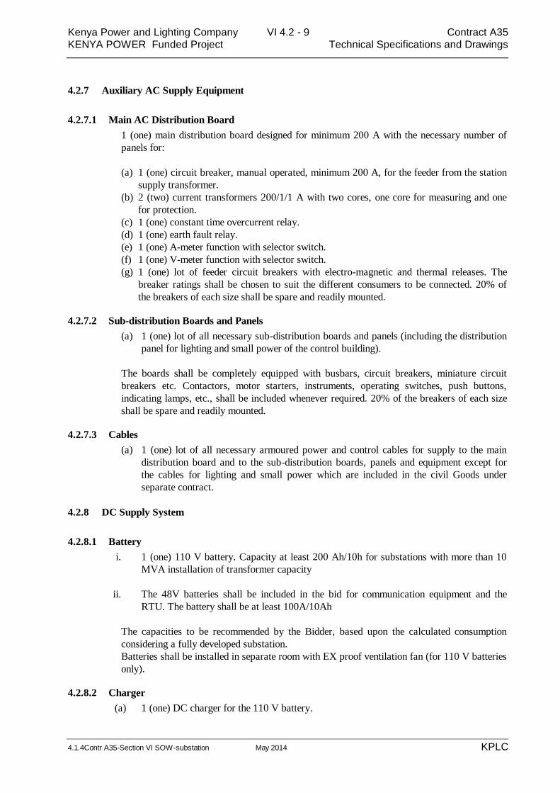
4.2.7 Auxiliary AC Supply Equipment
4.2.7.1 Main AC Distribution Board
1 (one) main distribution board designed for minimum 200 A with the necessary number of
panels for:
(a) 1 (one) circuit breaker, manual operated, minimum 200 A, for the feeder from the station
supply transformer.
(b) 2 (two) current transformers 200/1/1 A with two cores, one core for measuring and one
for protection.
(c) 1 (one) constant time overcurrent relay.
(d) 1 (one) earth fault relay.
(e) 1 (one) A-meter function with selector switch.
(f) 1 (one) V-meter function with selector switch.
(g) 1 (one) lot of feeder circuit breakers with electro-magnetic and thermal releases. The
breaker ratings shall be chosen to suit the different consumers to be connected. 20% of
the breakers of each size shall be spare and readily mounted.
4.2.7.2 Sub-distribution Boards and Panels
(a) 1 (one) lot of all necessary sub-distribution boards and panels (including the distribution
panel for lighting and small power of the control building).
The boards shall be completely equipped with busbars, circuit breakers, miniature circuit
breakers etc. Contactors, motor starters, instruments, operating switches, push buttons,
indicating lamps, etc., shall be included whenever required. 20% of the breakers of each size
shall be spare and readily mounted.
4.2.7.3 Cables
(a) 1 (one) lot of all necessary armoured power and control cables for supply to the main
distribution board and to the sub-distribution boards, panels and equipment except for
the cables for lighting and small power which are included in the civil Goods under
separate contract.
4.2.8 DC Supply System
4.2.8.1 Battery
i. 1 (one) 110 V battery. Capacity at least 200 Ah/10h for substations with more than 10
MVA installation of transformer capacity
ii. The 48V batteries shall be included in the bid for communication equipment and the
RTU. The battery shall be at least 100A/10Ah
The capacities to be recommended by the Bidder, based upon the calculated consumption
considering a fully developed substation.
Batteries shall be installed in separate room with EX proof ventilation fan (for 110 V batteries
only).
4.2.8.2 Charger
(a) 1 (one) DC charger for the 110 V battery.

Kenya Power and Lighting Company VI 4.2 - 10 Contract A35
KENYA POWER Funded Project Technical Specifications and Drawings
4.1.4Contr A35-Section VI SOW-substation May 2014 KPLC
(b) 1 (one) DC charger for the 48 V Battery.
The chargers shall be complete with instruments, breakers on AC and DC side, and
protection.
4.2.8.3 Switchboard
1 (one) switchboard 110 V DC.
The board shall have:
(a) 1 (one) circuit breaker with magnetic and thermal release for the feeder from earache
charger and battery.
(b) 1 (one) A-meter with shunt for each battery.
(c) 1 (one) V-meter with selector switch for the voltage between the poles and between poles
and earth for each battery.
(d) 1 (one) set of contacts on the front for banana jacks for the battery voltage and earth.
(e) 1 (one) battery monitoring devices with alarm contacts.
(f) 1 (one) lot of all necessary circuit breakers and miniature circuit breakers for the outgoing
feeders and circuits.
20% of the breakers of any size shall be spare and readily mounted.
4.2.8.4 Battery Conductors and Fuses
(a) 1 (one) set of conductors for the battery in the battery room.
(b) 2 (two) single pole fuse boxes with main fuses for the battery, placed on the wall outside
of the battery room, and two fuses for the battery monitoring device.
4.2.8.5 Sub-distribution Boards and Panels
(a) 1 (one) lot of all necessary sub-distribution boards and panels.
The boards shall be completely equipped with busbars, miniature circuit breakers, fuses, etc.
Contactors, motor starters, instruments, operating switches, push buttons, indicating lamps,
under-voltage relays with alarm contact, etc., shall be included whenever needed.
4.2.8.6 Cables
(a) 1 (one) lot of all necessary DC power supply cables, including wiring to the apparatus in
the switchyard.
4.2.9 Earthing System
An earthing network shall be installed comprising the following:
(a) 1 (one) lot of underground earthing system covering the platform and control building
with risers
(b) 1 (one) complete set of "above-floor" earthing system for the control building, as
applicable, with connections to the risers from the under-ground system.

Kenya Power and Lighting Company VI 4.2 - 11 Contract A35
KENYA POWER Funded Project Technical Specifications and Drawings
4.1.4Contr A35-Section VI SOW-substation May 2014 KPLC
4.2.10 Ancillary Equipment
4.2.10.1 Station Equipment
(a) 2 (two) self-contained, rechargeable, portable hand-held lights.
(b) 1 (one) audible alarm system with the necessary wiring.
4.2.10.2 Earthing Devices
(a) 1 (one) set of three phase portable earthing devices for 33kv with operating rods suitable
for earthing of the bay conductors and busbars.
(b) 1 (one) set of voltage indicator for 33kV with audible and visual indication for voltage
4.2.10.3 Cable Accessories
(a) 1 (one) lot of all connecting material, cable boxes and material for fixing the cables.
Terminals and terminal labels to the extent that this is not included in other sections.
4.2.10.4 Racks, Conduits, Ducts, etc
(a) 1 (one) lot of all cables, racks and trays to the extent necessary for the proper
distribution of cables.
All the conduits and protection tubes, wherever cables may deteriorate or where cable laying
may otherwise present difficulties.
4.2.11 Civil Works
4.2.11.1 Switchgear buildings
Switchgear building has been constructed.
Control Panels and medium voltage indoor switchgears of different Voltage levels shall be
installed in separate rooms
4.2.11.2 Cable Trenches
Cable trenches shall be constructed as specified in particular specifications and in scope of
work.
4.2.12 Training in control (SAS), Telecommunication and protection system
The training includes travel for the 4 (four) KPLC engineers as well as all course material and
other expenses shall be catered by the Contractor. The training shall be held at the
manufacturer's place. The training shall cover design, application, testing, commissioning and
maintenance of the relevant digital control and protection systems. The training course shall
have a minimum of 2 (two) weeks duration for SAS and Protection and one week for
communication. The cost of per diem and accommodation shall be met by KPLC.

Kenya Power and Lighting Company VI 4.2 - 12 Contract A35
KENYA POWER Funded Project Technical Specifications and Drawings
4.1.4Contr A35-Section VI SOW-substation May 2014 KPLC
4.2.13 Factory Acceptance Test
The Contractor shall arrange for 2 participants from KPLC and the Project Manager to
witness tests of major equipment listed below in the manufacturer’s plant. All routine tests
shall be carried out in the presence of the Employer’s representatives. The representatives
shall approve shipment of the equipment if they are satisfied that the requirements of the
specification are fully met
The Contractor shall arrange and meet the full cost of the air tickets and local transportation
33kV GIS switch gears disconnectors,earth switch, CTs, VTs and CBs
Protection and control system
Power cables
SAS
Telecommunications Equipment
FAT shall be carried out as prescribed in the particular technical specifications of the
equipment. The cost of per diem and accommodation shall be met by KPLC.
4.2.14 Test Equipment (TS –001)
Lap top computers: Two units set up with comprehensive software. The pc shall be
supplied with all the necessary accessories and ports and loaded with latest operating
system. The Lap top must be able to run all the relay and equipment software’s
supplied under the contract. The lap top specifications shall be approved by the
project manager. The Test equipment for Telecommunications shall be as described
in 4.1.6
4.2.15 Final documentation
As built drawings: 5 paper copies delivered in binders
3 CD-ROM copy (all drawings in auto cad)
1 set of transparencies
Operation and maintenance manuals: 2 copies per equipment
4.2.16 Site Offices and site facilities(LS-010, -011)
At the location where the Contractor will establish his main site administration:
At the location where the Contractor will establish his main site administration, an
office for site supervisors from the Project Manager with basic office furniture,
internet, telephone and access/use of fax and copier shall be provided by the
contractor for the implementation period
The contractor shall provide mobile phone for coordination of activities with project
manager and KES 10,000(ten thousand) monthly.
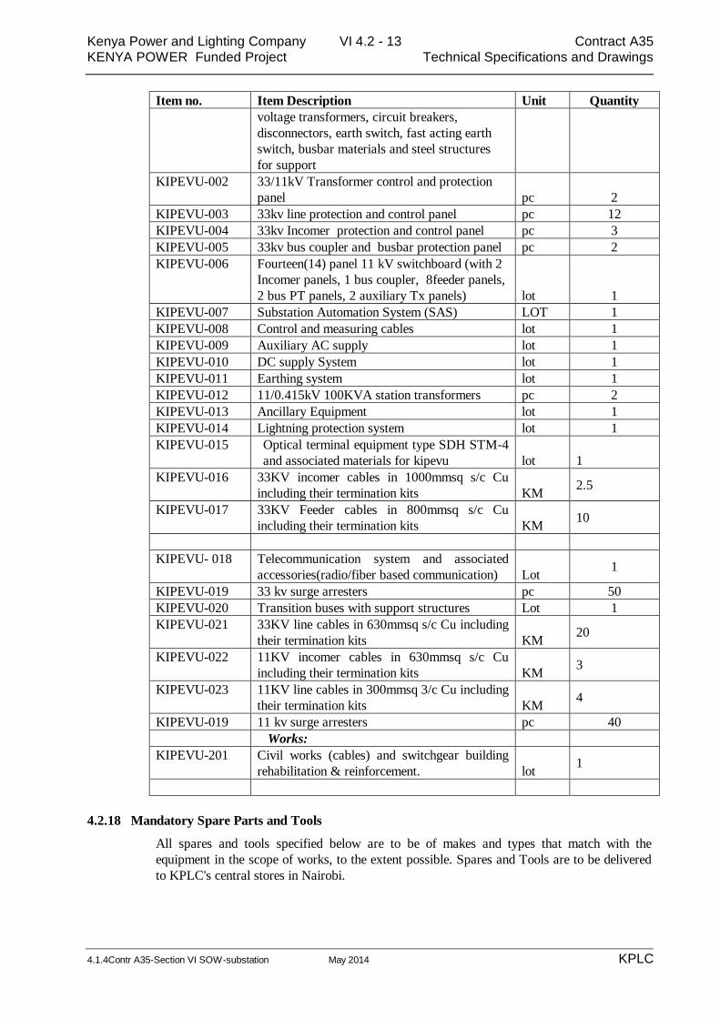
4.2.17 KIPEVU
Kipevu: New substation,
Item no. Item Description Unit Quantity
KIPEVU, 33KV GIS S/S
KIPEVU-001 Nineteen(19) bay Gas insulated 33KV
switchgear ( forteen(14) 33KV outgoing lines
and three(3) 33KV transformers incomers and
two(2) bus coupler ) double busbar
configuration. With current transformers, Lot 1
Kenya Power and Lighting Company VI 4.2 - 13 Contract A35
KENYA POWER Funded Project Technical Specifications and Drawings
4.1.4Contr A35-Section VI SOW-substation May 2014 KPLC
Item no. Item Description Unit Quantity
voltage transformers, circuit breakers,
disconnectors, earth switch, fast acting earth
switch, busbar materials and steel structures
for support
KIPEVU-002 33/11kV Transformer control and protection
panel pc 2
KIPEVU-003 33kv line protection and control panel pc 12
KIPEVU-004 33kv Incomer protection and control panel pc 3
KIPEVU-005 33kv bus coupler and busbar protection panel pc 2
KIPEVU-006 Fourteen(14) panel 11 kV switchboard (with 2
Incomer panels, 1 bus coupler, 8feeder panels,
2 bus PT panels, 2 auxiliary Tx panels) lot 1
KIPEVU-007 Substation Automation System (SAS) LOT 1
KIPEVU-008 Control and measuring cables lot 1
KIPEVU-009 Auxiliary AC supply lot 1
KIPEVU-010 DC supply System lot 1
KIPEVU-011 Earthing system lot 1
KIPEVU-012 11/0.415kV 100KVA station transformers pc 2
KIPEVU-013 Ancillary Equipment lot 1
KIPEVU-014 Lightning protection system lot 1
KIPEVU-015 Optical terminal equipment type SDH STM-4
and associated materials for kipevu lot 1
KIPEVU-016 33KV incomer cables in 1000mmsq s/c Cu
including their termination kits KM 2.5
KIPEVU-017 33KV Feeder cables in 800mmsq s/c Cu
including their termination kits KM 10
KIPEVU- 018 Telecommunication system and associated
accessories(radio/fiber based communication) Lot 1
KIPEVU-019 33 kv surge arresters pc 50
KIPEVU-020 Transition buses with support structures Lot 1
KIPEVU-021 33KV line cables in 630mmsq s/c Cu including
their termination kits KM 20
KIPEVU-022 11KV incomer cables in 630mmsq s/c Cu
including their termination kits KM 3
KIPEVU-023 11KV line cables in 300mmsq 3/c Cu including
their termination kits KM 4
KIPEVU-019 11 kv surge arresters pc 40
Works:
KIPEVU-201 Civil works (cables) and switchgear building
rehabilitation & reinforcement. lot 1
4.2.18 Mandatory Spare Parts and Tools
All spares and tools specified below are to be of makes and types that match with the
equipment in the scope of works, to the extent possible. Spares and Tools are to be delivered
to KPLC's central stores in Nairobi.
Kenya Power and Lighting Company VI 4.2 - 14 Contract A35
KENYA POWER Funded Project Technical Specifications and Drawings
4.1.4Contr A35-Section VI SOW-substation May 2014 KPLC
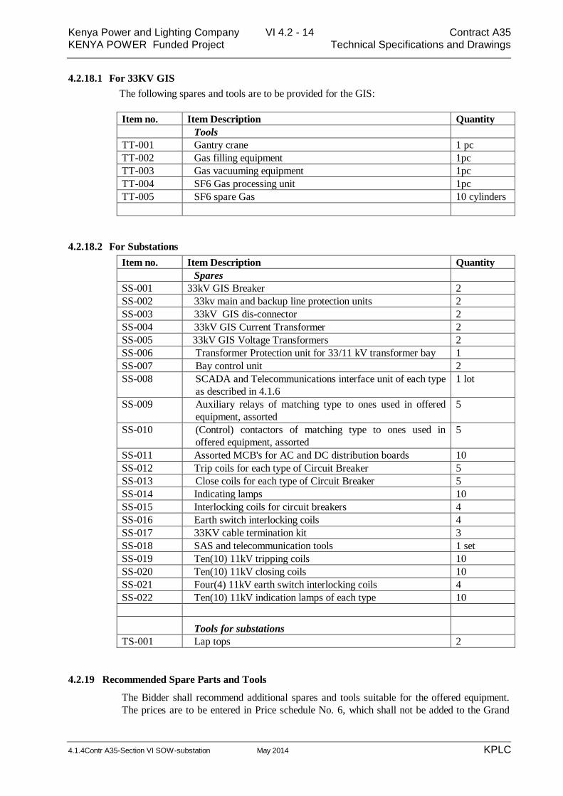
4.2.18.1 For 33KV GIS
The following spares and tools are to be provided for the GIS:
Item no. Item Description Quantity
Tools
TT-001 Gantry crane 1 pc
TT-002 Gas filling equipment 1pc
TT-003 Gas vacuuming equipment 1pc
TT-004 SF6 Gas processing unit 1pc
TT-005 SF6 spare Gas 10 cylinders
4.2.18.2 For Substations
Item no. Item Description Quantity
Spares
SS-001 33kV GIS Breaker 2
SS-002 33kv main and backup line protection units 2
SS-003 33kV GIS dis-connector 2
SS-004 33kV GIS Current Transformer 2
SS-005 33kV GIS Voltage Transformers 2
SS-006 Transformer Protection unit for 33/11 kV transformer bay 1
SS-007 Bay control unit 2
SS-008 SCADA and Telecommunications interface unit of each type
as described in 4.1.6
1 lot
SS-009 Auxiliary relays of matching type to ones used in offered
equipment, assorted
5
SS-010 (Control) contactors of matching type to ones used in
offered equipment, assorted
5
SS-011 Assorted MCB's for AC and DC distribution boards 10
SS-012 Trip coils for each type of Circuit Breaker 5
SS-013 Close coils for each type of Circuit Breaker 5
SS-014 Indicating lamps 10
SS-015 Interlocking coils for circuit breakers 4
SS-016 Earth switch interlocking coils 4
SS-017 33KV cable termination kit 3
SS-018 SAS and telecommunication tools 1 set
SS-019 Ten(10) 11kV tripping coils 10
SS-020 Ten(10) 11kV closing coils 10
SS-021 Four(4) 11kV earth switch interlocking coils 4
SS-022 Ten(10) 11kV indication lamps of each type 10
Tools for substations
TS-001 Lap tops 2
4.2.19 Recommended Spare Parts and Tools
The Bidder shall recommend additional spares and tools suitable for the offered equipment.
The prices are to be entered in Price schedule No. 6, which shall not be added to the Grand

Kenya Power and Lighting Company VI 4.2 - 15 Contract A35
KENYA POWER Funded Project Technical Specifications and Drawings
4.1.4Contr A35-Section VI SOW-substation May 2014 KPLC
Summary Prices. The recommended spares and tools are to be specifically discussed and
agreed on during contract negotiations


![Report on Ichchhapore substation Substation...2014/07/06 · Date:02/02/2018 Report on Ichchhapore substation Substation: SubstationEquipment: 1] PowerTransformer: A](https://img.pdfslide.net/doc/110x75/6082a7423c38c8542368e070/report-on-ichchhapore-substation-substation-20140706-date02022018-report.jpg)