Embed Size (px)
Citation preview
DEMO MANUAL SCP-5X1-EVALZ
Rev. 0
1
DESCRIPTION Demonstration circuit SCP-5X1-EVALZ is a companion hardware tool designed to integrate several voltage rails into a compact, single point terminal in a Signal Chain Power hardware evaluation matrix. It features five input ports and one output port, along with passive filtering op-tions.
Like all boards in the Signal Chain Power series, this board is designed to be easily plugged into other SCP boards to form a complete signal chain power system, enabling fast evaluation of low power signal chains. To evaluate this board, some universal SCP hardware is required, namely:
SCP-INPUT-EVALZ SCP-FILTER-EVALZ SCP-OUTPUT-EVALZ SCP-1X2BKOUT-EVALZ SCP-1X5BKOUT-EVALZ SCP-THRUBRD-EVALZ
To properly evaluate SCP series demo boards, you will need the SCP Configurator companion software. SCP Configurator can help you choose the right board and to-pology for your design.
Design files for this circuit board are available. All registered trademarks and trademarks are property of their respective owners
Table 1. Performance Summary
SYMBOL PARAMETER NOTES MIN TYP MAX UNITS
VIN(MAX) Max Input Voltage 50 V
VOUT(MAX) Max Output Voltage 50 V
IOUT(MAX) Max Output Current 2 A
ILED(MAX) Max Indicator LED Current See Configuration Section 30 mA
BOARD IMAGE
Figure 1. Signal Chain Power 5 × 1 Integration Board
DEMO MANUAL SCP-5X1-EVALZ
Signal Chain Power 5 × 1 Integration Board
DEMO MANUAL SCP-5X1-EVALZ
Rev. 0
2
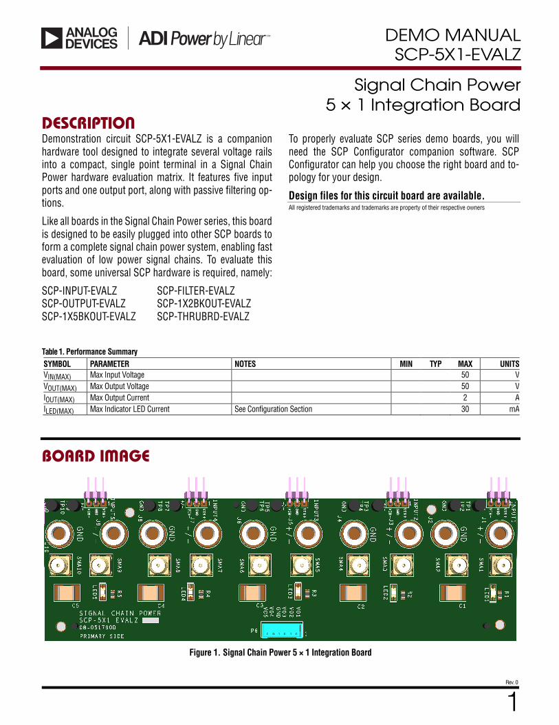
QUICK START PROCEDURE Demonstration circuit SCP-5X1-EVALZ is easy to set up to evaluate the performance of any SCP hardware con-figuration. Refer to Figure 2 and follow these steps:
1. The SCP-5X1-EVALZ ships with a bi-directional LED to indicate applied voltage. To set the limiting resistor, see “Configuration Settings” section, and modify the board accordingly. Be sure to check for open connections or solder shorts after making any modifications.
2. Connect the SCP-INPUT-EVALZ and SCP-OUTPUT-EVALZ boards to the SCP board under evaluation (refer to Figure 1) and connect the input board to a voltage source, VSOURCE. Connect the output board to a volt-meter or dynamic load. Slowly raise the input voltage until the SCP-5X1-EVALZ powers up the device under test into regulation and sweep VSOURCE through the de-sired range of operation.
NOTE: Make sure that the input voltage is always within spec. If using a dynamic load to measure output volt-age, make sure the load is initially set to zero.
3. Check for proper output voltages. The output should be regulated at the programmed value (±5%).
4. Once the proper output voltage is established, power off VSOURCE and similarly test other boards in the SCP system until all elements have been individually verified prior to assembling into the final circuit configuration.
NOTE: When measuring the input or output voltage rip-ple, use the optional SMA connector locations available on the input, output, 1 ´ 5, 1 ´ 2, and 5 ´ 1 breakout boards. Avoid using the test point connections with long scope leads.
Figure 2. Proper Measurement Equipment Setup (Use SMA connectors for Measuring Input or Output Ripple)
DEMO MANUAL SCP-5X1-EVALZ
Rev. 0
3
CONFIGURATION SETTINGS Demonstration circuit SCP-5X1-EVALZ is a companion hardware tool designed to integrate several voltage rails into a compact, single point terminal in a Signal Chain Power hardware evaluation matrix. It features five (5) in-put ports and one (1) output port, along with passive fil-tering options.
INDICATOR LED CURRENT
Table 2. LED Current-Limiting Resistor Selection Table
VIN (V) R1, R2, R3, R4, R5 (Ω) VIN (V) R1, R2, R3, R4, R5 (Ω)
2.5 24.9 23.0 1.05k
3.0 49.9 24.0 1.10k
3.3 9 25.0 1.15k
3.5 75 26.0 1.21k
4.0 100 27.0 1.24k
4.5 124 28.0 1.30k
5.0 150 29.0 1.33k
5.5 174 30.0 1.40k
6.0 200 31.0 1.43k
6.5 226 32.0 1.50k
7.0 249 33.0 1.54k
7.5 274 34.0 1.58k
8.0 301 35.0 1.65k
8.5 324 36.0 1.69k
9.0 348 37.0 1.74k
9.5 374 38.0 1.78k
10.0 402 39.0 1.87k
11.0 453 40.0 1.91k
12.0 499 41.0 1.96k
13.0 549 42.0 2.00k
14.0 604 43.0 2.05k
15.0 649 44.0 2.10k
16.0 698 45.0 2.15k
17.0 750 46.0 2.21k
18.0 806 47.0 2.26k
19.0 845 48.0 2.32k
20.0 909 49.0 2.37k
21.0 953 50.0V 2.43k
22.0 1.00k
OUTPUT CONNECTOR CONFIGURATION
Output connector P6 allows a single-point harness con-nection or PCB attachment to the integration board.
For harness attachment, use the Hirose Electric Co. part DF3-6S-2C with crimp pin DF3-2428SCC.
For attaching integration board to your system board, in-clude part DF3-6S-2DSA (25) in design CAD library.
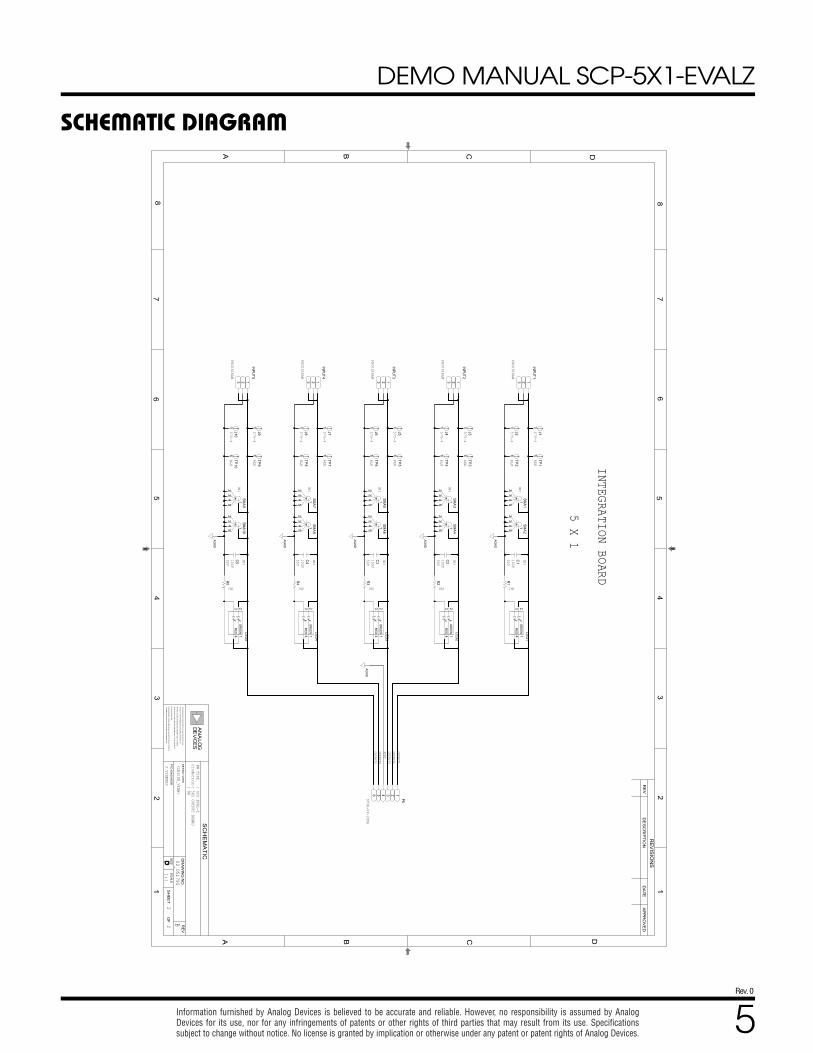
Please reference the schematic page included in this ap-pendix for the pinout connectivity of connector P6.
SIGNAL MEASUREMENT CONFIGURATION
Each channel has two (2) dedicated vertical SMA output connectors for easy connection to test or measurement equipment. Additionally, the banana jacks are spaced at 0.750” for use with BNC (female) to double stacking ba-nana plug type adapters (Pomona model 1269 or equiva-lent).
M
n 1 5
IN MIN AXLED
V 2.00V ;2.40VI
R = ®
- é ùë û=
DEMO MANUAL SCP-5X1-EVALZ
Rev. 0
4
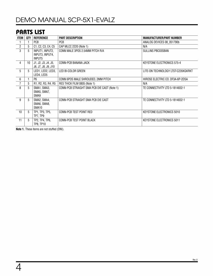
PARTS LIST ITEM QTY REFERENCE PART DESCRIPTION MANUFACTURER/PART NUMBER
1 1 PCB PCB ANALOG DEVICES 08_051790b
2 5 C1, C2, C3, C4, C5 CAP MLCC 2220 (Note 1) N/A
3 5 INPUT1, INPUT2, INPUT3, INPUT4, INPUT5
CONN MALE 3POS 2.54MM PITCH R/A SULLINS PBC03SBAN
4 10 J1, J2, J3, J4, J5, J6, J7, J8, J9, J10
CONN-PCB BANANA JACK KEYSTONE ELECTRONICS 575-4
5 5 LED1, LED2, LED3, LED4, LED5
LED BI-COLOR GREEN LITE-ON TECHNOLOGY LTST-C235KGKRKT
6 1 P6 CONN 6POS MALE SHROUDED, 2MM PITCH HIROSE ELECTRIC CO. DF3A-6P-2DSA
7 5 R1, R2, R3, R4, R5 RES THICK FILM 0805 (Note 1) N/A
8 5 SMA1, SMA3, SMA5, SMA7, SMA9
CONN-PCB STRAIGHT SMA PCB DIE CAST (Note 1) TE CONNECTIVITY LTD 5-1814832-1
9 5 SMA2, SMA4, SMA6, SMA8, SMA10
CONN-PCB STRAIGHT SMA PCB DIE CAST TE CONNECTIVITY LTD 5-1814832-1
10 5 TP1, TP3, TP5, TP7, TP9
CONN-PCB TEST POINT RED KEYSTONE ELECTRONICS 5010
11 5 TP2, TP4, TP6, TP8, TP10
CONN-PCB TEST POINT BLACK KEYSTONE ELECTRONICS 5011
Note 1. These items are not stuffed (DNI).
DEMO MANUAL SCP-5X1-EVALZ
Rev. 0
5 Information furnished by Analog Devices is believed to be accurate and reliable. However, no responsibility is assumed by Analog Devices for its use, nor for any infringements of patents or other rights of third parties that may result from its use. Specifications subject to change without notice. No license is granted by implication or otherwise under any patent or patent rights of Analog Devices.
SCHEMATIC DIAGRAM
INTEGRATION BOARD
5 X 1
22
<DESIGN_VIEW>
: NAProduct(s): 5X1 OUTPUT BOARDHW TYPE : SCP EVAL-Z
1:1
B02_051790
J VIERNES
50V
575-
4
10UF
50V
10UF
PBC0
3SBAN
DNI
50V
50V
10UF
DNI
50V
10UF
DNI
DNI
RED
575-
4
DNI
DNI
575-
4
DNI
10UF
DNI
575-
4
DNIDNI
PBC0
3SBAN
575-
4BLK
RED
BLK
PBC0
3SBAN
PBC0
3SBAN
575-
4BLK
RED
575-
4
575-
4
575-
4
BLK
RED
BLK
PBC0
3SBAN
575-
4RED
DNI
DNIDNI
DNI
DNI
DF3
A-6
P-2DS
A
INPUT5J9
TP7
C4
SMA5
C2 C1
SMA4
TP4
SMA2
R1
SMA7
LED4
TP8
J5
SMA1
INPUT4
J10
J8
TP10
TP9
INPUT3
INPUT2
J7 J6TP6
TP5
J4 J3 J2
TP3
TP2
INPUT1J1
TP1
R5
SMA9
SMA10
SMA8
C5
R4
LED5
SMA6
C3
R3
SMA3
R2
LED2
LED1
P6
LED3
OUTPUT2
AGNDOUTPUT3
OUTPUT4OUTPUT5
OUTPUT1
43
43
25
1
2
5
4
1
2
1
2
123 123
1 1 1
1 1 1
123 123
1 1 1
1 1 1
1 1 1
1 1
123
11
3
154
2
1
2345
35
4 115
2
2314
2314
153
24
45 1
23
34 1
1
54
33
54 1
2
2314
2314
2356
2314
RED
GREEN
RED
GREEN
RED
GREEN
AGND
AGND
AGND
AGND
RED
GREEN
RED
GREEN
AGND
AGND
D
THIS
DR
AW
ING
IS TH
E P
RO
PER
TY
OF AN
ALO
G D
EVIC
ES
INC
.
IN P
ART
, OR
US
ED
IN FU
RN
ISH
ING
INFO
RM
AT
ION
TO
OTH
ER
S,
OR
FOR
ANY
OT
HER
PUR
PO
SE D
ETR
IME
NTA
L TO
TH
E INTE
RES
TS
TH
E EQU
IPM
ENT
SH
OW
N HER
EO
N M
AY B
E PR
OTE
CTE
D B
Y PATE
NT
S
AC
IT IS NO
T TO
BE RE
PR
OD
UC
ED O
R C
OP
IED, IN
WH
OLE
OR
DR
AW
ING
NO
.
2
SCALE
DDD SIZE
D
RE
V
SH
EE
T
1 1
A
23
4
35
8
D
7
67
8
A B CC D
5
4
APPROVED
B
6
DESCRIPTIO
N
REVISIONS
OF
OLGE
OW
NED
OR
CO
NTR
OL
LED
BY O
WN
ED
AN
ALO
G D
EVIC
ES.
EANV
OF
AN
ALO
G D
EV
ICES
.
SCHEMATIC
S
PTD
EN
GIN
EE
R
DE
SIG
N V
IEW
REV
DATE
DEMO MANUAL SCP-5X1-EVALZ
Rev. 0
6 11/20 www.analog.com
© ANALOG DEVICES INC. 2020
ESD Caution ESD (electrostatic discharge) sensitive device. Charged devices and circuit boards can discharge without detection. Although this product features patented or proprietary protection circuitry, damage may occur on devices subjected to high energy ESD. Therefore, proper ESD precautions should be taken to avoid performance degradation or loss of functionality.
Legal Terms and Conditions By using the evaluation board discussed herein (together with any tools, components documentation or support materials, the “Evaluation Board”), you are agreeing to be bound by the terms and conditions set forth below (“Agreement”) unless you have purchased the Evaluation Board, in which case the Analog Devices Standard Terms and Conditions of Sale shall govern. Do not use the Evaluation Board until you have read and agreed to the Agreement. Your use of the Evaluation Board shall signify your acceptance of the Agreement. This Agreement is made by and between you (“Customer”) and Analog Devices, Inc. (“ADI”), with its principal place of business at One Technology Way, Norwood, MA 02062, USA. Subject to the terms and conditions of the Agreement, ADI hereby grants to Customer a free, limited, personal, temporary, non-exclusive, non-sublicensable, non-transferable license to use the Evaluation Board FOR EVALUATION PURPOSES ONLY. Customer understands and agrees that the Evaluation Board is provided for the sole and exclusive purpose referenced above, and agrees not to use the Evaluation Board for any other purpose. Furthermore, the license granted is expressly made subject to the following additional limitations: Customer shall not (i) rent, lease, display, sell, transfer, assign, sublicense, or distribute the Evaluation Board; and (ii) permit any Third Party to access the Evaluation Board. As used herein, the term “Third Party” includes any entity other than ADI, Customer, their employees, affiliates and in-house consultants. The Evaluation Board is NOT sold to Customer; all rights not expressly granted herein, including ownership of the Evaluation Board, are reserved by ADI. CONFIDENTIALITY. This Agreement and the Evaluation Board shall all be considered the confidential and proprietary information of ADI. Customer may not disclose or transfer any portion of the Evaluation Board to any other party for any reason. Upon discontinuation of use of the Evaluation Board or termination of this Agreement, Customer agrees to promptly return the Evaluation Board to ADI. ADDITIONAL RESTRICTIONS. Customer may not disassemble, decompile or reverse engineer chips on the Evaluation Board. Customer shall inform ADI of any occurred damages or any modifications or alterations it makes to the Evaluation Board, including but not limited to soldering or any other activity that affects the material content of the Evaluation Board. Modifications to the Evaluation Board must comply with applicable law, including but not limited to the RoHS Directive. TERMINATION. ADI may terminate this Agreement at any time upon giving written notice to Customer. Customer agrees to return to ADI the Evaluation Board at that time. LIMITATION OF LIABILITY. THE EVALUATION BOARD PROVIDED HEREUNDER IS PROVIDED “AS IS” AND ADI MAKES NO WARRANTIES OR REPRESENTATIONS OF ANY KIND WITH RESPECT TO IT. ADI SPECIFICALLY DISCLAIMS ANY REPRESENTATIONS, ENDORSEMENTS, GUARANTEES, OR WARRANTIES, EXPRESS OR IMPLIED, RELATED TO THE EVALUATION BOARD INCLUDING, BUT NOT LIMITED TO, THE IMPLIED WARRANTY OF MERCHANTABILITY, TITLE, FITNESS FOR A PARTICULAR PURPOSE OR NONINFRINGEMENT OF INTELLECTUAL PROPERTY RIGHTS. IN NO EVENT WILL ADI AND ITS LICENSORS BE LIABLE FOR ANY INCIDENTAL, SPECIAL, INDIRECT, OR CONSEQUENTIAL DAMAGES RESULTING FROM CUSTOMER’S POSSESSION OR USE OF THE EVALUATION BOARD, INCLUDING BUT NOT LIMITED TO LOST PROFITS, DELAY COSTS, LABOR COSTS OR LOSS OF GOODWILL. ADI’S TOTAL LIABILITY FROM ANY AND ALL CAUSES SHALL BE LIMITED TO THE AMOUNT OF ONE HUNDRED US DOLLARS ($100.00). EXPORT. Customer agrees that it will not directly or indirectly export the Evaluation Board to another country, and that it will comply with all applicable United States federal laws and regulations relating to exports. GOVERNING LAW. This Agreement shall be governed by and construed in accordance with the substantive laws of the Commonwealth of Massachusetts (excluding conflict of law rules). Any legal action regarding this Agreement will be heard in the state or federal courts having jurisdiction in Suffolk County, Massachusetts, and Customer hereby submits to the personal jurisdiction and venue of such courts. The United Nations Convention on Contracts for the International Sale of Goods shall not apply to this Agreement and is expressly disclaimed.