Embed Size (px)
Citation preview

SCREAM
Speech Controlled Responsive Electronics and Mechanics
Angelo Farfan, Heather Lawrence, Brett Silver
Group 21
Sponsored by the Boeing Company
1.0 Executive Summary…………………………………………………………………...1 2.0 Project Description…………………………………………………………………….2
2.1 Project Motivation and Goals…………………………………………………2 2.2 Objectives………………………………………….………………………….4 2.3 Project Requirements and Specifications ……………………………………..5
2.3.1 User Interface………………………………………………………..5 2.3.1.1 Microphone………………………………………………..5 2.3.1.2 Push Buttons………………………………………………6 2.3.1.3 LCD Display………………………………………………6 2.3.1.4 LED Lights………………………………………………...6
2.3.2 Power Supply Specifications………………………………………..6 2.3.2.1 AC/DC Converter Power Supply………………………….8
2.3.3 Single Supply Operational Amplifier (LM2904) Specifications……9 2.3.3.1 Bipolar NPN Switching Transistor (P2N2222A)…....…..11
2.3.4 Servo Motor Specifications………………………………………...12 2.3.4.1 NPN Darlington Transistor (TIP120) ……………………14 2.3.4.2 Normally Open Mode Fail Secure Electric Deadbolt ……15
2.3.5 Relay Control Unit specifications………………………………….15 2.3.6 Microcontroller Specifications……………………………………..18
2.3.6.1 Microprocessor…………………………………………..18 2.3.6.2 Microcontroller…………………………………………..18 2.3.6.3 Digital Signal Processor (DSP) …………………………19 2.3.6.4 Family ……………………………………………………19 2.3.6.5 Splitting the Workload…………………………………...19
2.3.7 Wireless Transceiver Specifications……………………………….19 2.3.8 Microphone Specifications………………………………………...20
2.3.8.1 Motorola Hint…………………………………….………22 2.3.8.2 Motorola Whisper………………………..………………22 2.3.8.3 Motorola Silver II………………………..………………22 2.3.8.4 Motorola Boom…………………………..………………22 2.3.8.5 Plantronics Voyager Legend…………………..…………23 2.3.8.6 Plantronics Marque2 M165………………………………23 2.3.8.7 Plantronics M55……………………………………….…23
2.3.9 Speech Recognition Circuit Specifications………………………...23 2.3.9.1 Speech Recognition IC (HM2007 IC)…………………...24 2.3.9.2 64KB External SRAM (HM6264B)……………………..24 2.3.9.3 Octal Latch IC (74HC573)……………………………….25 3.0 Research…..………………………………………………………………………….26 3.1 Existing Home Automation Systems (HAS) ………………………………..26
3.2 Technologies Applicable to a HAS…………………………………………..27 3.2.1 ZigBee……………………………………………………………...27 3.2.2 x10………………………………………………………………….28 3.2.3 Z-Wave…………………………………………………………….29 3.2.4 EnOcean……………………………………………………………30 3.2.5 INSTEON………………………………………………………….30

3.2.6 Bluetooth…………………………………………………………...30 3.2.7 IPv6 over Low power Wireless Personal Area Networks (6LoWPAN)……………………………...………………………………31 3.2.8 Wi-Fi, Wi-Fi Direct, Wi-Fi Peer-to-peer (P2P) ……………………31
3.3 Speech Recognition Overview……………………………………………….32 3.4 Components Needed to Implement SCREAM………………………………34
3.4.1 Input Module……………………………………………………….34 3.4.2 Access Point or Master Module……………………………………34 3.4.3 Light Control Module……………………………………………...34 3.4.4 Door Control Module………………………………………………35
3.5 Possible Architectures and Related Diagrams……………………………….36 3.5.1 Microcontroller…………………………………………………….36
3.5.1.1 MSP430 + Zigbee………………………………………..36 3.5.1.2 CC3200…………………………………………………..36 3.5.1.3 MSP430 + Sub 1GHz……………………………………37 3.5.1.4 ODROID-C1……………………………………………..37
3.5.2 Speech Recognition………………………………………………..37 3.5.2.1 Android…………………………………………………..37 3.5.2.2 HM2007………………………………………………….38 3.5.2.3 Windows…………………………………………………38
3.6 Servo Control System……………………………………………………….38 3.6.1 Servo Motor Control………………………………………………39 4.0 Hardware and Software Design Details……………………………………………..40
4.1 Power Supplies………………………………………………………………40 4.2 Door Control Unit …………………………………………………………...41 4.3 Relay Control Unit…………………………………………………………..42 4.4 Main Module Microcontroller-ODROID-C1………………………………..44 4.5 Door and Light Module Microcontroller - CC3200…………………………45
4.5.1 Power Modes………………………………………………………46 4.5.2 Power Requirements……………………………………………….47 4.5.3 Clocks……………………………………………………………...47 4.5.4 Peripherals………………………………………………………….48
4.5.4.1 Universal Asynchronous Receiver/Transmitter (UART)..48 4.5.4.2 Serial Peripheral Interface (SPI) ………………………...48
4.5.5 Memory…………………………………………………………….48 4.5.6 Cortex Processor Boot Sequence…………………………………..48
4.5.7 Using the CC3200’s Transceiver………………………………..…49 4.5.7.1 Networking………………………………………………50
4.6 Microphone…………………………………………………………………..51 4.7 Speech Recognition………………………………………………………….51 4.8 Design Constraints and Standards…………………………………………...56
5.0 Design Summary of Hardware and Software………………………………………..57 6.0 Prototype Construction and Coding………………………………………………….63
6.1 Parts Acquisition……………………………………………………………..63 6.2 Bill of Materials………………………………….…………………………..64
6.2.1 Headset……………………………………………………………..65 6.2.2 Main Unit………………………………………………..…………65 6.2.3 Door Unit…………………………………………………..………65 6.2.4 Power Control Unit…………………………………………...……66
6.3 PCB Vendor and Assembly………………………………………………….67 6.3.1 Design……………………………………………………………...67 6.3.2 Fabrication…………………………………………………………67
6.4 Final Coding Plan ……………………………………………………………69 7.0 Prototype Testing………………………………………………….…………………71
7.1 Hardware Test Environment…………………………………………………71 7.2 Unit Testing…………………………………………….……………………71
7.2.1 Door Control Unit………………………………………………….71 7.2.2 Speech Recognition Unit…………………………..………………72 7.2.3 Relay Control Unit…………………………………………………73 7.2.4 Wireless Transceiver Unit…………………….……………………73
7.2.4.1 Wireshark………………………………...………………73 7.2.4.2 Ubiqua with SmartRF Packet Sniffer ……………………75
7.3 Software Test Environment …………………………………………………76 7.3.1 Code Composer Studio (CCS) ………………………….…………76 7.3.2 Energia……………………………………………………..………76 7.3.3 Additional Software………………………………..………………76
7.4 Software Testing……………………………………………………………..77 7.5 Integrated System Testing ……………………………………………………81
7.5.1 Main Module and Headset…………………………………………81 7.5.2 Main Module and Door Module……………...……………………82 7.5.3 Main Module and Light Module…………………………...………82 7.5.4 Overall System Test………………………..………………………83
7.6 Presentation Environment ……………………………………………………84 8.0 Administrative Content………………………………………………………………84
8.1 Project Milestones ……………………………………………………………84 8.2 Project Budget and Finance Discussions…………….………………………85
8.2.1 Budget……………………………………………………...………85 8.2.2 Financial Discussions………………………………………………87
9.0 Project Summary and Conclusions………………………………………..…………88 10.0 Extending the Design……………………………………………………………….89
10.1 User Interface and App Development………………………………………89 10.2 Multiple Users………………………………………………………………89 10.3 Vocal Confirmation……………………………………………...…………89 10.4 Email, Text Alerts, and Remote Manipulation………..……………………89 10.5 Microphone Repeaters…………………………...…………………………90 10.6 Television Integration………………………………………………………90
A Copyright Permissions B Datasheets C References

D Figures and Tables Index

1
1.0 Executive Summary A speech recognition system simplifies a user’s interaction with a home automation system (HAS). Speech recognition applications can be classified into three broad groups: isolated word recognition systems where each word is spoken with pauses before and after, small vocabulary command and control applications, and large vocabulary continuous speech systems. Generally, a smart home system uses the mixture of the second and third cases. The main feature of a smart home is the ability to remotely command the functions of the home via its appliances. For example, controlling the amount of light in a room by a light switch. This is the command and control function. Most command and control applications have a small vocabulary size that reflects the operations required to control the equipment. For example, “television off” would turn the television off. However, more complex commands can be managed through a known set of alternatives, such as days of the week, percentages, or times of the day. As the number of alternative wordings increases, the task of listing all possible combinations and associating them with a given set of actions become unmanageable and so a grammar syntax is required that specifies, in a more abstract way, the words and phrases along with their permissible combinations. Minimizing the vocabulary used to control devices also allows the SCREAM system to minimize its size and cost. Unlike many HAS technologies, SCREAM runs on a wireless network secured by WPA2, controls an electric deadbolt, and provides a signal to manipulate power to electronic devices without using a core visual interface like a tablet. Vocal control from a wireless device allows the user the freedom to have their hands free while controlling their home and wired control provides better word accuracy. After speaking, the SCREAM system is to recognize speech commands, interpret them, and control the appropriate device. SCREAM is less expensive than other systems because there is no GUI, which removes the need for an expensive LCD display, and the number of electronic control units is scalable. This modularity allows a homeowner to expand or contract the number of units to fit the needs of their home. The system runs on low power to ensure that, although the system provides these features, it does not add significantly to a utility bill. Due to the popularity of home automation technologies it is necessary to keep security in mind to prevent unwanted entities from gaining access to the premises. Lastly, the system is easy enough to set up and use for the average person with minimal computer knowledge. The concept of using speech recognition in smart homes can be related to the voice recognition system used in the Joint Strike Fighter (JSF) cockpit developed by Boeing. The system incorporates speech recognition technology specifically designed and optimized for ultra high accuracy in a noisy cockpit environment. The device and related software allows pilots to avoid some manual tasks so that they can remain better focused on their flight environment. Speech recognition technology enhances the pilot’s aircraft management capabilities. Speech recognition systems can be used for multiple purposes. This concept can be expanded to homeowners. A HAS can improve the lifestyle and performance of its users while they are executing multiple tasks at home.

2
2.0 Project Description 2.1 Project Motivation and Goals
The formal idea of a home automation system (HAS) originated during the World's Fairs of the 1930s and has been a topic for many science fiction writers. For example, H.G. Wells wrote about automatic doors in The Sleeper Awakes published in 1899. Utopia, as theorized by science fiction writers and political ideologists alike, was associated with the idea of mitigated work through the use of machines and many automation methods aim to reduce the amount of work required to perform normal, often considered menial, tasks around the home. As case in point, wireless remotes could be used for vessels and vehicles to keep a person from having to physically be present to manipulate the device, an idea that Nikola Tesla patented in 1898. Automation is already a common facet in a first-world home as seen in washing machines to clean clothes, dishwashers to wash dishes, water heaters to remove the need to manually heat water for bathing, and thermostats to automate the temperature but these technologies are only a fraction of the devices that can be automated. One of the most famous homes, the home of Bill Gates, expounds on the possibilities that lie in home automation. Each person is pinned with an electronic tracking chip and as a person traverses the home lights turn on ahead of the chip and turn off behind it. The chip maintains data on everything a person does and makes adjustments as it learns that person's preferences, including musical tastes and television channels. When two people pinned with such chips enter a room the system attempts to compromise between the preferences of both. A "smart house," or a home that is equipped with lighting, heating, and electronic devices that can be controlled remotely as coined by the American Association of Housebuilders in 1984, began as a wired electrical system intended to provide power to multiple outlets, intended for a television and lighting, and a doorbell. 'Remotely' used to refer to another room located in the same domicile, but now the term 'remotely' has extended to include any location where an Internet-connected tablet or cell phone can reach. The boom of home automation is closely linked to the ability to control it from a tablet or touch screen device. Smart homes now contain any of the following automations: kitchen appliance and lighting, lawn watering and care, pet feeding, security systems, camera systems, audio and entertainment systems, window coverings, and utility usage to include both water and electric. Utility conservation is becoming more essential to saving both money and the environment. The average U.S. home uses 1,000 kilowatt-hours (kwh) of electricity per month - the equivalent of 79 gallons of gas. Vampire power, like clock displays and LEDs, can add an additional 10 percent to a power bill and 75 percent of the electricity used to power home electronics is generally consumed when the device is turned off or in an idle state. Saving even an infinitesimal amount of energy per home can be monumental in conserving energy when every home implements that knowledge. For

3
example, if every U.S. home replaced a single light bulb with an energy efficient light bulb the amount of energy that would be saved could light an additional 3 million homes for a year. Home automation, when faced with the rising costs of energy and the dwindling reserves of freshwater, could save families hundreds in utility costs per year and help preserve the environment. A HAS should save the homeowner on their electric bill. Often times if a user leaves a room for a few minutes, they do not want to walk to the light switch to turn it off. This problem can be further compounded when multiple light switches are on and are not located next to each other. Home automation can be used to motivate an individual to turn off lights that are not in use because they do not have to be physically present at the switch, but preferably a light should turn off automatically. Many first world nations, the United Stated included, have an aging population. Home automation technologies can solve a unique problem presented by the elderly and otherwise disabled. Health care costs, including nursing home costs, could be reduced as a person reaches end of life by extending the time a person can remain in their place of residence without, or with minimal, outside assistance. For a monthly subscription, companies, like ADT, Front Point Security, and AT&T are willing to provide 24/7 home monitoring for smoke, carbon monoxide, or glass breakage using sensors installed in key locations. There are also medical alert devices that a person can use when they have an accident, which calls an emergency number for them. For persons with limited mobility voice activated light control is used to help turn lights on and off and chair lifts can be installed to aid in traversing between floors. For the hard of hearing or hearing impaired, overhead lights or onboard LEDs can flash to indicate when a phone is ringing. Interactive voice response (IVR), like Siri, can be used to wake a person daily with the date, when medication needs to be taken, when medical appointments are, and even general house tasks that need to be done like taking out the garbage or recycling on the appropriate day. A smart refrigerator can be used to indicate when a particular food is low in supply and a smart oven can turn itself off if it reaches a certain temperature or is left on for too long. These technologies can help maintain independent living for longer, reducing the cost of nursing home or hospice care. A HAS should be easy to configure, run, and use regardless of visual capabilities. The cost of installing and using a home automation system has often hindered otherwise interested parties from using one. The aforementioned monthly subscription involves little to no effort to install or maintain on behalf of the user. For AT&T a basic energy package requires 200 dollars upfront for installation and a five-dollar monthly fee. Automation for the garage door is $50, a push button door lock is $100, and a touchscreen door lock is $150 with a $50 upfront installation fee and a five-dollar monthly fee. ADT’s Pulse program provides a basic home security service for a monthly service subscription of $47.99 with a 36-month contract and does not include video or home management. Video and home management are included with a more expensive subscription that entirely relies on a broadband connection; in the event that Internet or power is lost, those features are lost as well. Front Point Security also offers a subscription service for a minimum of $35 per month that includes intrusion protection, life safety, and fire and water protection. ‘Crash and Smash Protection’, or

4
reimbursement in the event of a successful burglary, remote access and control, text alerts, and light control can be added for an additional seven dollars. The highest tier of plans includes live video streaming, motion activated video recording, night vision capabilities, automated door locks, and energy management control for a total of $50 per month. Monthly subscriptions often come with high installation costs and a long minimum required contract. In order to motivate a user to install and use a HAS, the long term cost should be minimized. To achieve this, both the installation cost and the cost to maintain the system should be kept low. Home automation is still possible regardless of these obstacles. A personal home automation network can be controlled by a homeowner’s voice. The system would run on a secure network, be able to control door locks, and provide power to electronic devices. Replacing the tablet with a wireless Bluetooth earpiece would allow the user the freedom to have their hands free while still maintaining control of their home. While wearing the wireless headset and speaking, the SCREAM system is to recognize speech commands, interpret them, and control the appropriate device. SCREAM is much less expensive than other systems because there is no GUI and the number of electronic control units is scalable. Lastly, the system is easy enough to set up and use for the average person.
2.2 Objectives
SCREAM allows users to vocally control their HAS. There are not as many HAS systems that use vocal control available on the market which means that SCREAM would have more value due to scarcity. Vocal control allows the user to have their hands free and that benefits those who do not want to control their systems on a touch-based interface or those who are unable to use a touch-based interface. Vocal controls are handled by the HM2007 chip, which performs speech recognition independently or as a slave to a host processor. The chip recognizes several words lasting a second each, which reduces the vocabulary the user can control the system with and keeps the cost of the embedded system low. An embedded system is easier to manufacture and troubleshoot as most of the requirements the system needs are handled on hardware. With a single microcontroller as the center node the overall size of SCREAM was small. Each device that is SCREAM enabled is also small due to its embedded nature. The embedded system is more robust with no software to install, as everything the circuit needs is always be present on board. The size makes the system more attractive because it takes up less space and the onboard software makes the system easier to use. SCREAM uses little power to operate. The system can go into idle when not in use so the system needs less power to operate. It controls, at a minimum, access to a door with the use of a transmitter/receiver unit to an electric deadbolt and switches lights on and off at a user’s vocal or local command. This means that both functions must have appropriate vocal controls available on the chip and these commands activate each system accordingly.

5
2.3 Project Requirements and Specifications
SCREAM is easy to make space for and move around. Therefore, all SCREAM components are light enough to lift even if a user has issues with mobility and it is small enough that it is unnoticeable when it is implemented in a home. A user is able to operate the SCREAM system with some leeway and freedom without having to stand next to the unit in order to vocally control the modules. This mobility is at the user’s discretion. There are a minimum amount of words that the system identifies in order to control the modules in the house. There are enough words, for example, to control the television, the lights, and the door in this implementation. The system is able to accurately identify the words used to reduce user frustration. In order to reduce the amount of maintenance that SCREAM would need to operate, the system efficiently uses power to help conserve battery life. This would reduces the amount of time the user needs to change and charge batteries. Finally, for the module that operates the door, an electric deadbolt must be able to be actuated to lock and unlock a door. A summation of these requirements are detailed in Table 1. 1 Remote stations can communicate to the base station up to 10 meters away 2 Speech recognition chip identifies up to 40 words 3 Speech recognition chip operates with 95% word accuracy 4 Mechanical door opener operates for 24 hours before batteries need replacement 5 Home stations dimensions is below 20 cm by 20 cm by 10 cm 6 Remote electrical stations dimensions is below 10 cm by 10 cm by 10 cm 7 Remote mechanical stations dimensions is below 20 cm by 20 cm by 20 cm 8 Home stations weight is below 1 kg 9 Remote electrical stations weight is below 500g 10 Remote mechanical stations weight is below 2 kg 11 LCD display must be easy to read and provide clear user feedback 12 Low latency between voice command and actuation Table 1 - Project Specifications 2.3.1 User Interface
A user interfaces with the device through the following methods. SCREAM receives inputs in the form of voice commands through the microphone. Additional inputs are provided through the use of a keypad and a rotary encoder, which provide a means for the user to train the speech recognition circuit during first time use. The device provides the user with feedback in the form of a single LCD display and multiple LED lights.
2.3.1.1 Microphone A microphone acts as the primary means of entering information to the system and after

6
the initial user setup the microphone can act as the only input source. A headset with a microphone is provided for demonstration purposes but the user can determine which type of microphone can be used - wired or wireless. Replacement would require that the new microphone have an adapter that fits in the same port. During the first time setup the user uses the microphone to train the system to remember certain voice commands. These recordings are held in the systems memory and can be re-recorded at any time. For the user to be able to maintain full control of the system they are required to be wearing or within range of the microphone in order for it to receive voice commands. If using a wireless headset, it is required for the user to regularly recharge the microphones battery. Any time the user is not home or is not using the system, the microphone is placed in its charging station.
2.3.1.2 Push Buttons The main station’s housing contains a keypad that corresponds directly to the acceptable voice commands. The user is required to use the buttons during the system’s initial setup but they can retrain them at any time should they choose. The push buttons are used to train each of the commands individually. To train a command the user holds down one of the buttons that corresponds to a single household appliance and speaks the command they want to use later to activate the device into the microphone. The message is stored within the device and is used for identify voice commands later.
2.3.1.3 LCD Display A Liquid Crystal Display is embedded into the main station’s housing. It is used as the primary source of feedback to the user and assists in debugging. The LCD is sufficiently large that it displays a message stating the machine’s current state and error messages that are useful to the user. In order to properly display all numbers and letters SCREAM uses a 20 by 40 segment display. The display also allows the user to adjust its contrast. This allows the display to be easily legible in a wide range of ambient lighting conditions.
2.3.1.4 LED Lights Light Emitting Diodes are used in both the main stations and the outlying client stations. The main station contains lights that indicate the various states the system is in. When the unit is powered on, the LED designated for power is lit. There is also a LED that flashes when an audio sample is being recorded. Lastly, next to the push button that corresponds to each of the client stations is an LED that indicates whether each device is turned on or off. This allows the user to visually see which stations are in use without having the check them all individually. LEDs are also used on the client stations. A single light is used to indicate whether the device is functioning and an additional light indicates if the device is providing power or not. 2.3.2 Power Supply Specifications
It is important that the power supply meets the requirements needed for this system to

7
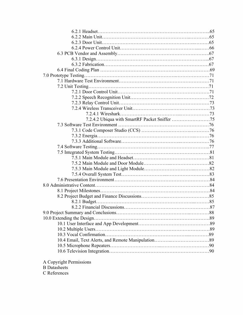
operate. It is common to meet the desired performance specifications and then try to minimize the power consumption. The minimal power required to obtain these specifications are then considered and integrated into good designs. SCREAM uses different types of power supplies for each specific part of the HAS. The main communication module uses an AC/DC converter to supply 10W of power to the ODROID-C1. The ODROID-C1 supplies the 0.6W of power through one of its I/O pins to the speech recognition circuit (HM2007). The AC/DC converter helps avoid the unnecessary use of batteries. This means that the speech recognition IC is not at risk to lose power and lose communication with the transceivers implemented to control the home appliances. Each of the CC3200 launchpads used for the control units of the HAS gets its required power from 2 AA batteries. During active mode, the CC3200 uses pin 2 to supply 3 V to a determined unit depending on the user’s command. The electric PCB uses a 9V battery as a power supply for the TMP relay. The electric PCB controls the current flow from the 9V battery to the TMP relay depending of the high or low signal that is received from pin 2 of the CC3200. The TMP relay tab contacts are connected to the power supply coming from the wall outlet. The tab contacts control the power source coming from a wall outlet, which normally supplies around 110 to 120 AC volts (Equivalent AC current 15 to 20 amps) at 60 Hz. The door PCB performs a similar function to control the current flow to the electric deadbolt. However, the door PCB is capable to control a higher amount of current than the electric PCB. A servo motor was intended to be used to actuate a door deadbolt, but the electric deadbolt was used instead. The servo was replaced because it could not provide the necessary force to actuate the door deadbolt. The electric deadbolt provides the necessary force to lock/unlock the door and requires a low amount of power to operate. The electric deadbolt requires 12 W (12VDC 1A) of power, which is provided by a Li-ion rechargeable battery. The input of the door PCB is connected to the 12V Li-ion rechargeable battery and the output is connected to the electric deadbolt, which supplies the necessary power to the electric deadbolt when the door needs to be locked. The LM2904 op amp was intended to be implemented to amplify the DC signal coming from one of the GPIO pins from the CC3200. However, low power transistors were used instead to control the current supply to the TMP relay and the electric deadbolt. Table 2 shows the power supply specifications for each element that was implemented in the project. The highlighted units in the table were not implemented in the final design of SCREAM.
8
Device Required Supply
Voltage Required Current Power supply HM2007 IC(SRC) 5 V 300 mA ODROID-C1 I/O pin CC3200 Launchpad 3 V 59 mA 2 AA batteries OP AMP (LM2904) 6 V 0.1 mA N/A Servo Motor 6 V 7 mA N/A TMP relay 9 V 89.1 mA 9V battery ODROID-C1 5 V 2 A AC/DC charger Electric Deadbolt 12 V 1 A 12V rechargeable battery Electric PCB 3 V 10.75 mA CC3200 pin 2 Door PCB 3 V 10.75 mA CC3200 pin 2
Table 2 - Power Supply Specifications 2.3.2.1 AC/DC Converter Power Supply In recent years, AC/DC converters have been increasingly used in the industrial, commercial, and military environment. This increment is due to the advantages that these devices can offer, which are high efficiency, compact sizes, and moderate weight. Based on these facts the AC to DC converter is the best choice to implement the integral part for the power supply unit of SCREAM. The AC/DC converter is responsible for taking the regular AC voltage supply of 110/120 ACV coming from the wall outlet, and providing a constant DC output voltage of 5 DCV. The output voltage remains constant which means it is regulated whether the load current changes or there are fluctuations in the input AC voltage. AC/DC converters are composed of a transformer, a full wave rectifier, a filter, and regulator. The transformer contains two huge copper coils, one between the two terminals of the input power supply and other between the two terminals of the output. For this specific conversion case, a step down transformer is used, which converts high voltage to low voltage. The rectifier converts the AC voltage output of the transformer to a DC voltage. It reverses the polarity of one half of the period of the AC signal making both parts to have the same polarity. The output from the rectification process is DC. however is not constant. To fix this issue a capacitive filtering is needed to smoothen the output. Using a simple low pass filter at the output of the rectifier helps give a smoother output. The final stage is using a voltage regulator to eliminate any minimal fluctuations. A simple zener diode based regulator is perfect to take care of this issue because zener diodes have a tendency to have a fixed voltage between its two terminals when reversed biased. When the input voltage changes, the existing current through the Zener diode also changes inversely keeping the output constant. For the simplicity to implement the AC/DC converter, a mobile phone device charger is used to perform the AC to DC conversion task. The charger supplies 5 VDC to the

9
ODROID-C1. The ODROID-C1 can cycle its input current between 0.5 A to 2 A, which means that any input current on that range is enough to power up the unit. Once the unit is powered up, the ODROID-C1 is capable to supply the required power through one of its I/O pins to the speech recognition circuit (HM2007). The ODROID-C1 supplies 1.5W(5 VDC 300 mA) of power to the SRC. Table 3 gives the spec values for the AC/DC power adapter charger for the ODROID-C1.
Item Specification Input Voltage 100 to 240 ACV Input Frequency 50 to 60 Hz Output Voltage 5 DCV Output Current 2 A
Table 3 - AC/DC Power Adapter Specifications
2.3.3 Single Supply Operational Amplifier (LM2904) Specifications
The LM2904 op amp was intended to amplify the low signal coming from pin 2, which is one of the GPIO pins from the CC3200. The op amp was supposed to take the output from pin 2, amplify the low signal and then supply its output to either relay or electrical deadbolt. However, the op amps require an external power supply in order to operate, which leads to each unit to consume more power. In addition, to accomplish the purpose to supply the require power to each unit, the final design was going to be more complex increasing the number of needed elements, which will considerably increase the size of the design. The P2N222A BJT transistor and the TIP120 Darlington transistor were used instead of the LM2904 op amps. Both transistors were implemented to the final design for the electric and door units with the purpose to control the TMP relay and electric deadbolt without the need to amplify signal and to reduce the required amount of power used in the system. Sections 2.3.3.1 and 2.3.4.1 give a more detailed explanation of how the P2N2222A and TIP120 operate in the HAS. Single supply applications have increased as a result of the popularity of portable equipment. Most portable systems operate with a single battery. Small size batteries that work perfectly with small electronic designs sometimes do not provide the enough voltage supply to power up this specific device. For this type of circumstance a single supply op amp comes to play the role to amplify the small DC voltage signal, and provide the amplified signal to the device. SCREAM uses a single supply op amp to amplify the small DC signals coming from the output of the transceiver MCU chips. The transceiver MCUs can only provide an output of 2.4 VDC, which does not meet the spec of 6 VDC require to set the relay or the servo in active mode. Since the relay units and servo require having a positive voltage supply, a non-inverting amplifier circuit is implemented to amplify and supply this necessary voltage. This non-inverting amplifier is based on having an input voltage (MCU output

10
voltage) connected to the non-inverting terminal and have to two resistors connected to the inverting terminal (One resistor across the inverting terminal and ground and the other resistor across the inverting terminal and the output). The resistors play a big role on this amplification process because in order to attain the required voltage gain of 2.5 to amplify a 2.4 VDC to 6 VDC depends on these resistors values. Picking the right op amp to implement a desired function is not an easy task. There is a wide variety of op amps with different specs and functions that might not work to respect to the design of the power supply for the servo motor and relays. In addition, there are some other factors that need to be considered like the availability of the device, the size, and the price. Table 4 shows the comparison of the op amps that could be used for the design of the power supply.
Item TLC27L7 LM358 LM158 LM2904 Single supply voltage range 3V/16V 3 V/32 V 3 V/32 V 3 V/26 V Dual supplies ±1.5V/±8V ±1.5V/±16V ±1.5V/±16V ±1.5 V/±13 V Input offset voltage 1.5 mV 2 mV 1mV 3 mV Input offset current 300 pA 5 nA 2 nA 2 nA High Level Output Voltage 4.2 V 28 V 28 V 24 V Low Level Output Voltage 50 mV 5 V 5 V 5 V CMRR(Common-mode rejection ratio) 95 dB 85 dB 85 dB 80 dB Output current 30 mA 20 mA 20 mA 20 mA Supply current 0.015 mA 1.2 mA 0.5 mA 0.1 mA Large Signal Voltage Gain 150 V/mV 100 V/mV 100 V/mV 100 V/mV Output Current 60 mA 40 mA 40 mA 40 mA Cost $0.88 $0.95 $2.13 $0.89
Table 4 - Comparison of Single Supply Op Amplifiers

11
Item MC33174 MCP602 LM3900 OP291 Single supply voltage range 3V/44V 2.7 V/6 V 4.5 V/32 V 2.7 V/12 V Dual supplies ±1.5V/±22V ------------- ±2.2V/±16V ------------- Input offset voltage 2 mV 2 mV 1mV 1 mV Input offset current 5 nA 1 pA ------------- 11 nA High Level Output Voltage ------------ ------------ 29.5 V 3 V Low Level Output Voltage ------------ ------------- 0.2 V 10 mV CMRR(Common-mode rejection ratio) 90 dB 90 dB 85 dB 90 dB Output current ------------- ----------- 20 mA 20 mA Supply current ------------- ------------ 6.2 mA -------------- Large Signal Voltage Gain 500 V/mV ------------- 2.8 V/mV -------------- Output Current ------------ ------------- ------------ -------------- Cost $3.95 $1.00 $4.49 $4.00
Table 4 - Comparison of Single Supply Op Amplifiers (Continued)
Making this comparison between all of these selected op amps helped to pick the most efficient and suitable device that to accomplish the desired performance and functionality for the power supply amplification. After comparing all of these devices, LM2904 is the best choice in respect to the desired specifications and reasonable cost. 2.3.3.1 Bipolar NPN Switching Transistor (P2N2222A) The P2N2222A transistor is used in the relay control unit (RCU) PCB to control the current flowing from the 9V battery to the high power TMP relay. The P2N2222A is used as a current control switch, which means the collector and the emitter are the switch terminals and the base is the switch handle. In other words, the small base current can be made to control a much larger current between the collector and emitter. The purpose of the switching application of the transistor only works when it operates either in cutoff or saturation mode in the system. The cutoff mode happens when the CC3200 does not send a high level signal or the system is inactive, which means that the base-emitter and base-collector junctions are not forward bias and the effective resistance between the collector and emitter is big, making the transistor act as an opened-circuit. The saturation mode happens when the CC3200 sends a high level signal through pin 2, which makes the base-emitter and base-collector junctions to be forward bias. In addition, during saturation mode the transistor sets the effective resistance between the collector and emitter to be really small and sets the collector current to be at its maximum value acting like a short circuit, which allows the necessary amount of current to flow to the relay. The base of the P2N2222A is connected to a 270 Ω resistor, which is in charge to control the amount of current flowing from the CC3200 to the base of the transistor. The

12
amount current flowing through the collector depends on two factors, which are the amount of current flowing through the base and the current gain of the transistor. The table 5 shows the specifications for the P2N2222A to operate in the system. In addition, the table includes the specific values of the base-emitter voltage (Vbe), collector-emitter voltage (Vce), collector current and current gain during saturation mode.
Item Specification Base-emitter voltage (Vbe) 0.6 V Collector-emitter voltage (Vce) 0.3 V Current gain 100 Base-emitter voltage (Vbe) saturation mode 0.85 V Collector-emitter voltage (Vce) saturation mode 0.1 V Current gain saturation mode 10 Collector current saturation mode 90 mA Maximum collector current 500 mA
Table 5 - Electrical Specifications for P2N2222A transistor 2.3.4 Servo Motor Specifications
A low power DC servo motor was intended to be part of the final design for the door control unit of SCREAM, but an electric deadbolt was used instead. The servo was not used in the door control unit because it could not apply enough force to actuate the deadbolt from the door. Another negative factor was the way the servo was going to be attached to the door, which requires screwing holes through the door making the installation of the system more complicated. The electric deadbolt is low power consumption, easy to install, and suitable for any kind of door. Section 2.3.4.2 gives a more detailed explanation how the electric deadbolt is implemented in the door control unit of SCREAM. Servo motors are used in many applications, they are small in size and are very energy efficient. These features are great to operate remote-controlled or radio-controlled systems. SCREAM uses a generic high torque servo motor to implement a simple rotation open/close function for an automated door of a house. The servo circuitry is built right inside the motor unit and has a positionable shaft, which usually is fitted with a gear (as shown Figure 2). The motor is controlled with an electric signal, which determines the amount of movement of the shaft. When the shaft of the motor is at the desired position, power supplied to the motor is stopped. If not, the motor is turned in the appropriate direction. The desired position is sent via electrical pulses from the wireless MCU chip through the signal wire. The motor's speed is proportional to the difference between its actual position and desired

13
position. So if the motor is near the desired position, it turns slowly, otherwise it turns quickly.
In addition, the implemented servo motor for this project uses a connector that has three colored wires, which are black for ground, red for power and white for the signal line. The servo motor is controlled by pulses on the signal line that are referenced to the ground line, which is the return path both for servo power and the control signal. The pulse width corresponds to the position of the servo. For this specific servo the pulse width is in the range from 0.7 to 2.3 ms corresponding to the servo’s “neutral” point. This neutral point is not necessarily the midpoint of the servo’s maximum available range. Making the pulse shorter makes the servo go one way; making the pulse longer makes the servo go the other way.
The tables 6-8 show the specifications that are required in order to perform the desired task, which in this case is locking/unlocking the door when the user interfaces with the speech recognition circuit. The mechanical specifications help with interfacing the servo motor with the door’s deadbolt lock. The servo was going to be attached to the door using a metal frame according to its dimensions given in the table. In addition, the electrical and control specifications describe the voltage required to power on the servo motor, the amount of torque force that was going to be distributed it in order to unlock/lock the door, and the speed of the motor gear with respect to the voltage supply.
Item Specification Size A:40.8mm B:20.1mm C:38mm D:49.5mm Weight 40g ±0.2(1.41oz) Gear type Plastic Gear Limit angle 200°±5° Motor Metal brush motor Connector wire 300mm ±5 mm Horn type Plastic
Table 6 - Mechanical Specifications for the Servos
Operating voltage range 4.8 V 6 V Idle current (at stopped) 5 mA 7 mA No load speed 0.18 sec/60° 0.16 sec/60° Rating current (at no load) 160 mA 190 mA Peak stall torque 69.56 oz.in 83.47 oz.in Stall current 980 mA 1100 mA
Table 7 - Electrical Specifications for the Servos
14
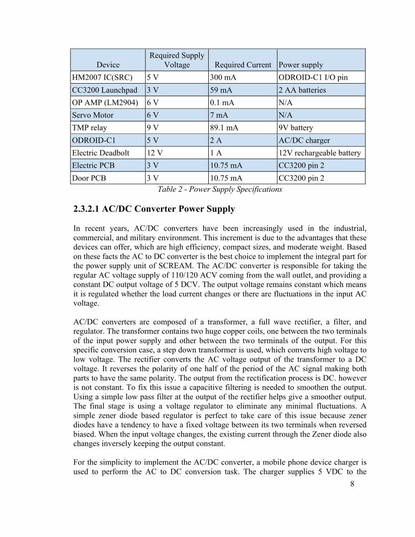
Item Specification Command Signal Pulse width modification Amplifier type Analog comparator Pulse width range 0.7 – 2.3 ms Neutral position 1.5 ms Running degree 180 degrees Rotating direction Counterclockwise Table 8 - Control Specifications for the Servos
2.3.4.1 NPN Darlington Transistor (TIP120)
The TIP120 Darlington transistor is used in the door control unit (DCU) PCB to control the current flowing from the 12V Li-ion rechargeable battery to the electric deadbolt. Similarly to the P2N2222A, the TIP120 is used as a current control switch, which means the collector and the emitter are the switch terminals and the base is the switch handle. In other words, the small base current can be made to control a much larger current between the collector and emitter. The purpose of the switching application of the transistor only works when it operates either in cutoff or saturation mode in the system. The cutoff mode happens when the CC3200 does not send a high level signal or the system is inactive, which means that the base-emitter and base-collector junctions are not forward bias and the effective resistance between the collector and emitter is big, making the transistor act as an opened-circuit. The saturation mode happens when the CC3200 sends a high level signal through pin 2, which makes the base-emitter and base-collector junctions to be forward bias. In addition, during saturation mode the transistor sets the effective resistance between the collector and emitter to be really small and sets the collector current to be at its maximum value acting like a short circuit, which allows the necessary amount of current to flow to the electric deadbolt. The base of the TIP120 is connected to a 390� resistor, which is in charge to control the amount of current flowing from the CC3200 to the base of the transistor. The amount current flowing through the collector depends on two factors, which are the amount of current flowing through the base and the current gain of the transistor. The following table shows the specifications for the TIP120 to operate in the system. In addition, the table includes the specific values of the base-emitter voltage (Vbe), collector-emitter voltage (Vce), collector current, and current gain during saturation mode.

15
Item Specification Base-emitter voltage (Vbe) 2.5 V Collector-emitter voltage(Vce) 3 V Current gain 1000 Base-emitter voltage(Vbe) saturation mode 1.5 V Collector-emitter voltage(Vce) saturation mode 0.75 V Current gain saturation mode 250 Collector current saturation mode 1A Maximum collector current 4A
Table 9 - Electrical Specifications for TIP120 Darlington transistor 2.3.4.2 Normally Open Mode Fail Secure Electric Deadbolt The normally open (NO) mode fail secure electric deadbolt is used to perform the lock/unlock function for the door module. The electric deadbolt operates at 12 W (12 VDC 1 A). The electric deadbolt consists of the main body that is attached to the door and the magnetic base that is attached to the door frame. The main body dimension is 28x200x39 mm and the magnetic base is 25x90x25mm. The two main components are in contact when the door is closed. The electric deadbolt operates when the solenoid of the main base is energized, a current passing through the solenoid creates a magnetic flux that causes the magnetic base to interface with the main base, creating an unlocking/locking action.
The electric deadbolt uses a timer to control the unlocked position while the door is opened, and the main base and magnetic base are separated. The timer can be set to 0, 3 or 6 seconds. The solenoid of the electric deadbolt has two wires that are connected to a terminal block of the DCU board. A 12V 3800 mAh rechargeable battery is connected to a power jack that is connected to the DCU board supplying the power required of 12 W to make the electric deadbolt to actuate when the main module sends a command. 2.3.5 Relay Control Unit specifications
Relays are implemented to perform another important task, which is controlling the power supply coming from the wall outlet to the specific home appliance. Each relay unit receives a signal from the wireless receiver MCU chip according to the user’s commands. Depending on this signal the relay makes the pole (or switch) close or open, which allows or blocks the power supply from the outlet to the device.
There is a broad selection of relay units to be considered in order to implement this type of wireless control for home appliances. One important factor that needs to be considered before choosing the right relay is if the unit would be capable of holding up the voltage supply from the outlet (110 to 120 AC volts) and amount of current (15 to 20 amps).

16
Another couple factors to be considered are the size (Relay dimension need to be as small as possible) and the price of the relay. Table 10 shows a comparison of the relay units that could be implemented to the design of the power supply control unit used in SCREAM to control the on/off function of the home appliances.
Item T90 G5NB G6B G2R-1ZA Type Power Relay Power Relay Power Relay Power Relay DC Coil Voltage 6V 5 V 5 V 5V Maximum AC voltage 277 VAC 250 VAC 380 VAC 380 VAC Rated Voltage 277 VAC 250 VAC 250 VAC 250 VAC
Relay Construction Non-Latching N/A Single winding latching
Double winding latching
Maximum DC Voltage Relay N/A 24 VDC 24 VDC 48 VDC AC Coil Voltage N/A N/A N/A 12 VAC Coil Current 150 mA 40 mA 40 mA 167 mA Coil Resistance 40 ohm 125 ohm 125 ohm 30 ohm Contact Arrangement SPDT SPST SPST SPDT Maximum Current Rating 30 A 5 A 8 A 16 A
Pin count 6 4 6 5 Maximum Pick Up Voltage 4.5 VDC N/A N/A N/A Weight 20 g 4 g 4.6 g 17 g Minimum Dropout Voltage 0.6 VDC N/A N/A N/A Contact Form 1 Form C SPST SPST SPDT Operating Temperature -55 to 85°C -40 to 70°C -25 to 70°C -40 to 70°C Operating Time 15 ms 10 ms 10 ms 15 ms
Dimension 30.5 x 24.13 x 17.27 mm
20.5 x 15.3 x 7.2 mm
20 x 10 x 10mm
29 x 25.5 x 13.5 mm
Cost $2.62 $1.92 $5.14 $3.58 Table 10 - Comparison for Relay Units
According to these requirements and specifications, the best choice was to use an electromagnetic power relay (T90 series). This specific relay is a 1 Form C relay, which it can be characterized as SPDT (Single Pole Double Throw). SPDT Single Pole Double Throw Relays have three connections. These three connections are Common, Normally Open, and Normally Closed.
The T90 electromagnetic power relay was intended to be used in the final design for the relay control unit, but a Panasonic JT-N TMP high power switching relay was used instead. The T90 power relay could not be implemented because there was a power

17
related issue to the final design of the PCB for the light module. The original design had the T90 power relay contacts attached to the PCB. The contacts of the T90 power relay were supposed to be connected to a high amount of power coming from the wall outlet. In order to handle that much power the thickness of the PCB has to be at least 3 oz and trace thickness in the board has to be 471 mils. According to these factors, the price increased considerably to get the PCBs manufactured. The Panasonic TMP relay has tab connectors on the top surface, which allows it to connect the contacts of the relay to the wall outlet power connector by using jumper wires. Using the jumper wires helped to complete the connection of the unit without using the PCB to connect the contacts of the relay to the wall outlet connector. Using this relay decreased the amount of work and reduced the price to get the PBCs manufactured.
The Panasonic TMP relay is a 1 Form C relay, which it can be characterized as SPDT (Single Pole Double Throw). SPDT Single Pole Double Throw Relays have three connections. These three connections are Common, Normally Open, and Normally Closed. When the relay is off, the common is connected to the normally closed connection of the relay. When the relay coil is energized (9 VDC is applied), the Common swings over to the normally open connection of the relay. Single Pole Double Throw relays offer the advantage to have a normally open and a normally closed contact set in one relay. The moveable contact transfers continuity from one stationary contact to the other when the coil is energized or de-energized. Voltage isolation is then between opposing stationary contact and the moveable contact.
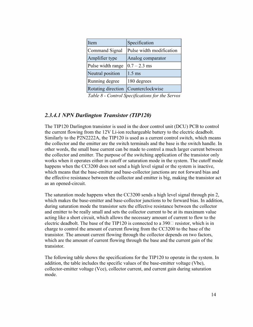
The TMP relay is able to hold up the desired power source coming from the wall outlet and make the proper switch on time, allowing the required amount of power flow to the device. The package design helps the assembly process save space that was used on the PCB. In addition, the price of this relay is moderate and affordable, which helps to economize and to decrease the budget expenses. Table 11 gives the specification for the Panasonic TMP relay.
18
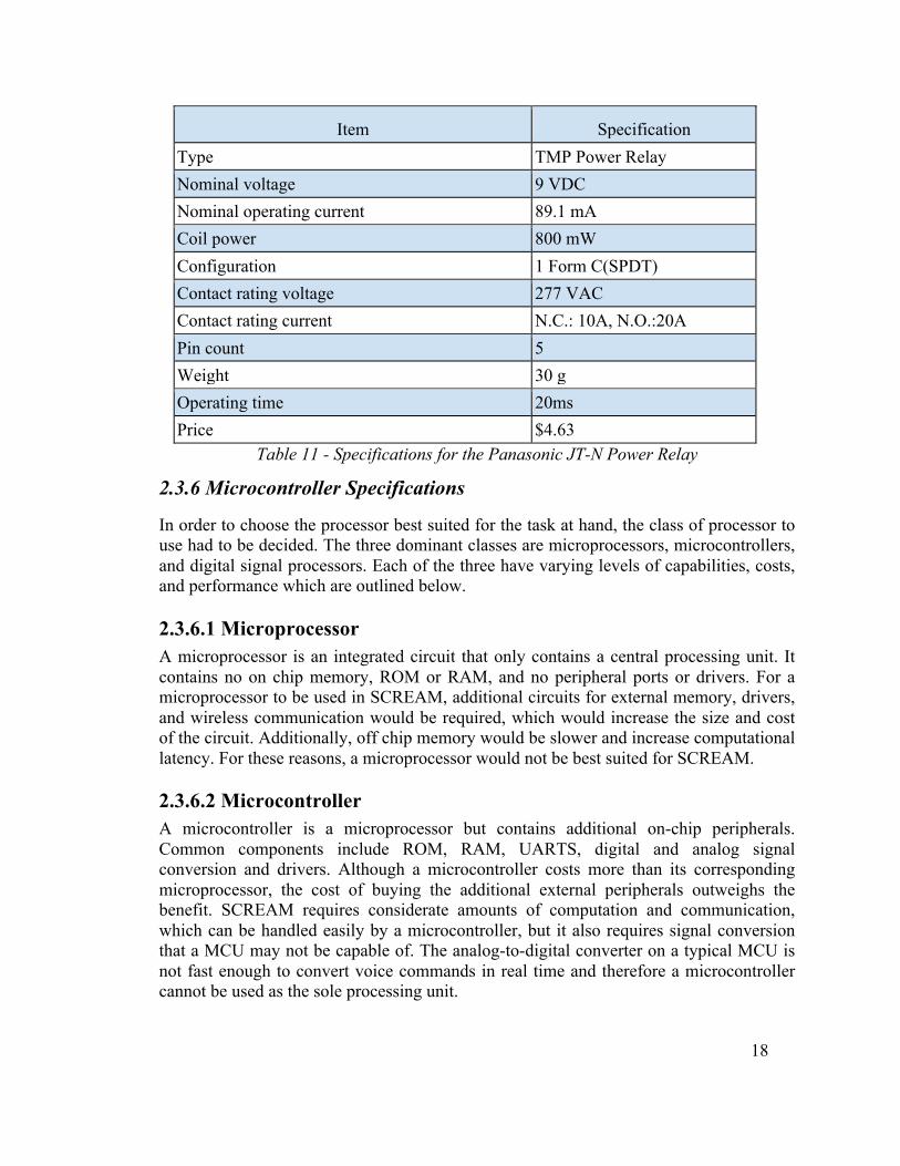
Item Specification Type TMP Power Relay Nominal voltage 9 VDC Nominal operating current 89.1 mA Coil power 800 mW Configuration 1 Form C(SPDT) Contact rating voltage 277 VAC Contact rating current N.C.: 10A, N.O.:20A Pin count 5 Weight 30 g Operating time 20ms Price $4.63
Table 11 - Specifications for the Panasonic JT-N Power Relay
2.3.6 Microcontroller Specifications
In order to choose the processor best suited for the task at hand, the class of processor to use had to be decided. The three dominant classes are microprocessors, microcontrollers, and digital signal processors. Each of the three have varying levels of capabilities, costs, and performance which are outlined below.
2.3.6.1 Microprocessor A microprocessor is an integrated circuit that only contains a central processing unit. It contains no on chip memory, ROM or RAM, and no peripheral ports or drivers. For a microprocessor to be used in SCREAM, additional circuits for external memory, drivers, and wireless communication would be required, which would increase the size and cost of the circuit. Additionally, off chip memory would be slower and increase computational latency. For these reasons, a microprocessor would not be best suited for SCREAM.
2.3.6.2 Microcontroller A microcontroller is a microprocessor but contains additional on-chip peripherals. Common components include ROM, RAM, UARTS, digital and analog signal conversion and drivers. Although a microcontroller costs more than its corresponding microprocessor, the cost of buying the additional external peripherals outweighs the benefit. SCREAM requires considerate amounts of computation and communication, which can be handled easily by a microcontroller, but it also requires signal conversion that a MCU may not be capable of. The analog-to-digital converter on a typical MCU is not fast enough to convert voice commands in real time and therefore a microcontroller cannot be used as the sole processing unit.

19
2.3.6.3 Digital Signal Processor (DSP) A digital signal processor shares many of the capabilities that a microcontroller has but it has the added benefit of being able to easily implement many signal processing algorithms. Additional hardware allows for common processing operations to be completed in a relatively low number of clock cycles. Due to the speech processing required by SCREAM a digital signal processor would be an ideal candidate for the main processing unit. The additional processors required to control the power relays do not require the ability to processes large quantities of signals so a DSP would not be required and a microcontroller is used instead.
2.3.6.4 Family There are three prevailing companies in the field of processor development and manufacturing. Intel, AMD, and ARM each have an array of strengths and weakness, but they ultimately differ on three fields: performance, power, and cost. Intel’s processors are considered by most people to have the highest level or performance for all around usage. However, this is at the expense of cost and power consumption, both of which are a major concern for an embedded system. AMD, considered to be Intel’s main competitor in the field of personal computing, offers a cost efficient alternative at only a small decrease in performance. The last manufacturer, ARM has recently become a major player in the field of mobile and embedded processing. They offer a lost cost and power efficient solution that is ideal for SCREAM. ARM processors have lower performance, in metrics of clock speeds and throughput, but are sufficient for the project’s needs.
2.3.6.5 Splitting the Workload There are three main jobs the main processor is the system is responsible for: voice recognition, signal processing, and wireless communication. These three tasks are very different in nature and therefore it is not likely to find a single processor that is ideal for each task. For this reason the team has decided to split the job between two separate circuits. There is DSP to handle voice recognition and a microcontroller to handle the signal processing and communication. The integrated circuit responsible for voice recognition works with its own external memory and when necessary this circuit sends data to the microcontroller. The microcontroller is responsible for interoperating this data and wirelessly communicating with remote microcontrollers that control the power relays. 2.3.7 Wireless Transceiver Specifications
The SCREAM system's main unit needs to be able to relay data to and from devices at the user's request. The user needs to know if the command did not work and needs to be reissued. SCREAM creates this necessary user feedback via LEDs on the main unit. In order to turn this LED on the main unit needs to both transmit and receive data from SCREAM enabled devices on the network that also need to be able to send and receive data from the main unit. This is possible through a transceiver. The main unit is expected to control the slave units that allow the user to control devices. The slave units should

20
then respond with a signal, regardless of whether or not the action was completed. This back and forth relaying of signals wirelessly describes a half-duplex requirement where the receiver is silenced while transmitting and the transmitter is silenced when receiving. This prevents damage to the other side of the transceiver. Half duplex is cheaper (as full duplex units are more expensive to manufacture) to implement and adds a trivial limitation to the system. It is impossible for the main unit to receive data while transmitting and vice versa. Transceivers, regardless of top-level protocol, are generally made using radio frequency (RF) communications. For embedded applications it is possible to use optical communication or infrared communication to transmit wirelessly, but both require line-of-sight which would not allow SCREAM to work as intended. Effective RF design is notoriously complex due to the sensitivity of radio circuitry and the necessity of proper antenna layout. In addition, it can be very difficult to achieve operation at the appropriate FCC designated frequency. Therefore, using a premade RF module is optimal due to the time constraints associated with the development of SCREAM. It is common for IC manufacturers to place RF modules on the same chip as a processor dedicated to a specific communications protocol resulting in a complete system on a chip (SoC). Thus, the transceiver can be grouped with the processor in its own unit. Texas Instruments makes SoC implementations for both ZigBee and Wi-Fi that are already IEEE 802.15.4 compliant. The host microcontroller, however, needs additional units to process the vocal commands. 2.3.8 Microphone Specifications
Microphones are acoustic-to-electric transducers that convert air pressure variation into electrical signals. For SCREAM, there needs to be an input mechanism that relays a user's commands into an electrical signal for use by the main device. A dynamic microphone works on the principle of electromagnetic induction. Sound is converted to electrical energy via a permanent magnet attached to a diaphragm. The diaphragm moves with the changes of air pressure variation. The magnet vibrates through a conductive coil that lies within the magnet's magnetic field. A varying current proportional to the air pressure variation is produced in the coil. A common problem with this type of microphone is that the diaphragm does not respond linearly to all audio frequencies. Higher quality dynamic microphones often have different diaphragms, each responsible for responding to a certain frequency, that produce separate currents and are combined into one signal later. Dynamic microphones are relatively inexpensive to manufacture and are resistant to moisture and feedback. A condenser microphone uses the idea of capacitance to convert acoustical energy to electrical energy. The diaphragm is made of a light material that vibrates and acts as one plate of a capacitor. The two plates have a voltage across them, which is applied by an external power source such as a battery or phantom power. Vibration causes the distance to change between the two plates that change the capacitance. When the plates are closer together the capacitance increases and a charge current if formed. When the plates move
21
apart the capacitance decreases and a discharge current occurs. This type of microphone generates a stronger signal than that from a dynamic microphone. Condenser microphones produce a flatter frequency response than dynamic microphones but are also prone to distortion at high sound levels, which could be a problem if used for SCREAM. A similar type of condenser microphone, the electret condenser microphone, replaces the phantom power needed by the capacitor with a polarized ferroelectric material that requires no polarizing voltage and is thus easier to manufacture. However, they often have a preamplifier integrated into the circuit which still requires external power. Monophonic versions of this microphone use a 3.5 mm plug that carries power to the preamplifier instead of providing a stereo signal. This specialized type of condenser microphone is often used for cellphones, computers, PDAs, headsets, and lavaliers due to decent signal response and low cost. This type of microphone is ideal for SCREAM. Frequency responses of a microphone are often mapped on the polar plane and called polar patterns. For the purposes of SCREAM, an omnidirectional polar pattern, or a pattern that is equally responsive for all 360 degrees, could be used as it is equally responsive no matter where the microphone is placed, however it could also pick up room noise. Likewise, bidirectional, hypercardioid, supercardioid, and shotgun microphones should be avoided because of the risk of external noise pickup. Subcardioid or cardioid polar patterns are optimal for SCREAM as respond the most to the direction they are pointed and shield sound from other directions. A pop filter or a windscreen could be helpful in eliminating peaks in vocal transmissions. When speaking, the 's', 't', and 'p' sounds can be over pronounced and can cause distortion in the 4000 to 10000 hertz range. This may have an impact on vocal interpretation by the HM2007 chip. Pop filters are nylon coverings that are held by a wireframe on the outside of the microphone. If distortion is present during testing when using vocal commands like 'TV' or 'light' a makeshift pop filter or windscreen can be improvised by sewing a small nylon or foam covering over the end of the microphone if the microphone purchased does not already come with one. In order for the microphone to reach most of the areas across modern American households the microphone must be wireless and must be able to transmit clearly across the domicile. Thirty feet is enough to encompass nine hundred square feet; this is large enough for most apartments and small households but is not enough to encompass larger manses. This puts a limitation on the SCREAM system, but could be expanded upon in later versions using a repeater. Two common microphone manufacturers, Motorola and Plantronics, offer wireless microphones using the Bluetooth 2.1 and later protocols and offer headsets that transmit 33 feet or more which is ideal for the requirements of the system. The microphone needs to either come paired with a USB dongle that the main unit can read the electrical data from or needs to be able to pair with a separate dongle that the main unit can understand. There are many makers of Bluetooth enabled headsets but two of the primary developers are Motorola and Plantronics.

22
2.3.8.1 Motorola Hint This headset is unique in that it comes with an infrared proximity detector which turns the unit on once it is within a certain distance of a heat source, in this adaptation the unit turns on once seated inside the human ear. Once in the charging case the unit automatically turns off. It allows 3.3 hours of talk time, which is a bit low for headsets of this class, but has a standby time of 33 hours, which makes this unit a bit more attractive. It supports up to Bluetooth 3.0, which is above the preference of Bluetooth 2.1 for security purposes. This unit does not come with a dongle, so the dongle would have to be purchased separately. It supports noise reduction and echo cancellation, which would be helpful to clean up the audio signal for the HM 2007 and perhaps increase its vocal recognition. This unit excels at talk range with 150 feet of range between the unit and the receiving station that would increase the range of SCREAM considerably. The disadvantage of this unit, however, is the extreme cost of $150 retail that is more than double the original budget of the headset component.
2.3.8.2 Motorola Whisper This wireless microphone also uses Bluetooth 3.0 and provides noise reduction and echo cancellation. This headset, however, provides volume adjustment for the user and an increased talk time of six hours. Improved from the Motorola Hint, the Whisper allows the user 300 feet of roaming instead of 150 feet. It also has an increased standby time of six days. Unfortunately, this headset is also $150 retail, which makes it undesirable for SCREAM. This headset sits in front of ear like a boom microphone. This unit does not come with a dongle, so the dongle would have to be purchased separately.
2.3.8.3 Motorola Silver II This headset is also Bluetooth 3.0 compliant and offers noise reduction and echo cancellation. Both the talk time and the standby time are increased from previous units. Talk time is increased to 14 hours with a charging case and standby time is increased to 12 days. It sits behind the ear, similar to many earbud headphone models. This headset is a bit more affordable at $130 retail, but again, is too pricey for the desired outcomes of SCREAM. This unit does not come with a dongle, so the dongle would have to be purchased separately.
2.3.8.4 Motorola Boom This unit pairs using NFC that would require the user to physically tap the unit to the Bluetooth dongle. This also infers that the dongle chosen would require NFC abilities. Noise reduction, volume adjustment, and echo cancellation are standard features. Audio prompts are available that notify the user of battery levels. The Boom headset has a rapid charge feature that allows the user to talk for 2.5 hours for only 15 minutes of charging. On a full charge the unit allows six hours of talk time and eight days in standby mode. It sits in the ear and hooks over the ear. At $60 retail and 300 feet of roaming, this microphone could be used for SCREAM. This unit does not come with a dongle, so the dongle would have to be purchased separately.

23
2.3.8.5 Plantronics Voyager Legend The Voyager Legend headset allows a user to pair with two devices instead of just one that would allow the user to speak with the master module and answer calls from another paired device like a mobile phone. Like many Motorola product lines, it offers noise cancellation using active digital signal processing. Plantronics does not list the roaming distance on this model, so it is difficult to rank this device in comparison to Motorola devices. This unit offers moisture protection and voice control to answer or ignore calls and does not come with a dongle, so the dongle would have to be purchased separately. The battery power on this unit allows for 7 hours of talk time and 11 days in standby mode, which is comparable to Motorola. At $100 it is a little over the budgeted amount for SCREAM
2.3.8.6 Plantronics Marque2 M165 The Marque2 M165 is priced within SCREAM's budget at $60 and also allows for voice commands to answer and ignore calls. It also provides for noise cancelling and power saving features but does not come with a dongle, so the dongle would have to be purchased separately. In addition, it offers a "DeepSleep" mode extends the battery life up to 180 days, which is well beyond any headset examined thus far. Talk time on this device is about standard, however, at 7 hours. Plantronics does not list the roaming distance on this model, so it is difficult to rank this device in comparison to Motorola devices.
2.3.8.7 Plantronics M55 The M55 is the most desirable model among the Plantronics devices. It responds to voice commands and offers a power saving mode. The roaming distance is a standard 33 feet. The battery lasts 11 hours for active talk time, on standby the battery life is increased to 16 days, and on the "DeepSleep" mode the time is increased to 150 days. It is shaped like a standard boom microphone that fits in front of the ear. The cost of the M55 is $50 retail, which makes it desirable in terms of SCREAM’s budgetary concerns but it does not come with a dongle, so the dongle would also have to be considered. 2.3.9 Speech Recognition Circuit Specifications
The speech recognition circuit is the most significant part of the project. This device must be able to take voice commands from a user and then send that signal wireless to the selected MCU chips. The speech recognition circuit is composed of the speech recognition IC (HM2007), an external 64KB SRAM (HM6264B IC) needed to store data, a 3 volt battery that backs up the memory of the external SRAM when the system is off because SRAM is volatile, octal latch IC (74HC573), which in charge to transfer the 8 bit output from the speech recognition IC to the 8 KB external SRAM, and 4x3 keypad that was implemented to help training the board or to store each command that needs to be performed when the user interfaces with the circuit.

24
2.3.9.1 Speech Recognition IC (HM2007 IC) The HM2007 IC is the main component of the speech recognition circuit. The HM2007 is a single chip CMOS voice recognition LSI circuit with the on chip analog front end, voice analysis, recognition process, and system control functions. The chip can recognize 40 words with the max length time of 0.9 sec per word or 20 words with the max length time of 1.92 sec per word. Also, the HM2007 is a low consumption power IC, it only requires a single 5 volt power supply in order to operate. A voice recognition system using the HM2007 IC can be composed of an external microphone, a keyboard, 64K SRAM and some other components. Table 12 gives a more detailed description about the electrical characteristics of the HM2007 IC. The specifications shown in the table present a clear idea about the necessary amount of power needed to activate the HM2007 and the response time of the system. These factors are important to implement the final design of the power supply for SCREAM.
Item Specification Supply Voltage 5 VDC Response Time 300 ms Operating Current 6 mA Output Drive Current 1.5 mA Output Sink Current 1.5 mA Input Leakage Current 0.1 µA Input Current (Pull down) 200 µA Output Data Enable Width 280 ns Output Data Holding Time 480 ns Memory Enable Width 560 ns Address Setup Time (to Memory Enable) 280 ns Memory Enable to Data (Reading Starting) 280 ns Memory Write (Write signal) 560 ns
Table 12 - Speech Recognition IC (HM2007)
2.3.9.2 64KB External SRAM (HM6264B)
The HM6264B IC is used as the 64 KB external SRAM for the HM2007 IC. The HM6264B supports the HM2007 to store the trained words that are used at the recognition phase. The HM6264B is a 64k-bit static RAM organized by 8-kword × 8-bit. This device realizes higher performance and low power consumption by 1.5 µm CMOS process technology. Some beneficial features of using the HM6264B are the high speed

25
process, low power consumption, completely static memory, so no clock or timing strobe required, and capability to achieve a battery backup operation. Table 13 gives a more detailed description about the electrical characteristics of the SRAM HM6264B. The specifications shown in the table present a clearer idea of the power needed to activate the external SRAM. HM62624B is soldered to the PBC and connected to the speech recognition IC to contribute with an extended storage data space. These characteristics have great significance on the final design for the power supply for the speech recognition unit.
Item Specification Supply Voltage 5 V Access Time 85/100 ns (max) Operating Power Supply Current 7 mA Input Pulse Levels 0.8 to 2.4 V Average Operating Power Supply Current 30 mA Standby Power Supply Current 3 mA Power Dissipation 1 W Output Low Voltage 0.4 V Output High Voltage 2.4 V Input High Voltage 2.2 V Input Low Voltage 0.8 V Read Cycle Time 100 ns
Table 13 - 64 KB External SRAM (HM6264B IC)
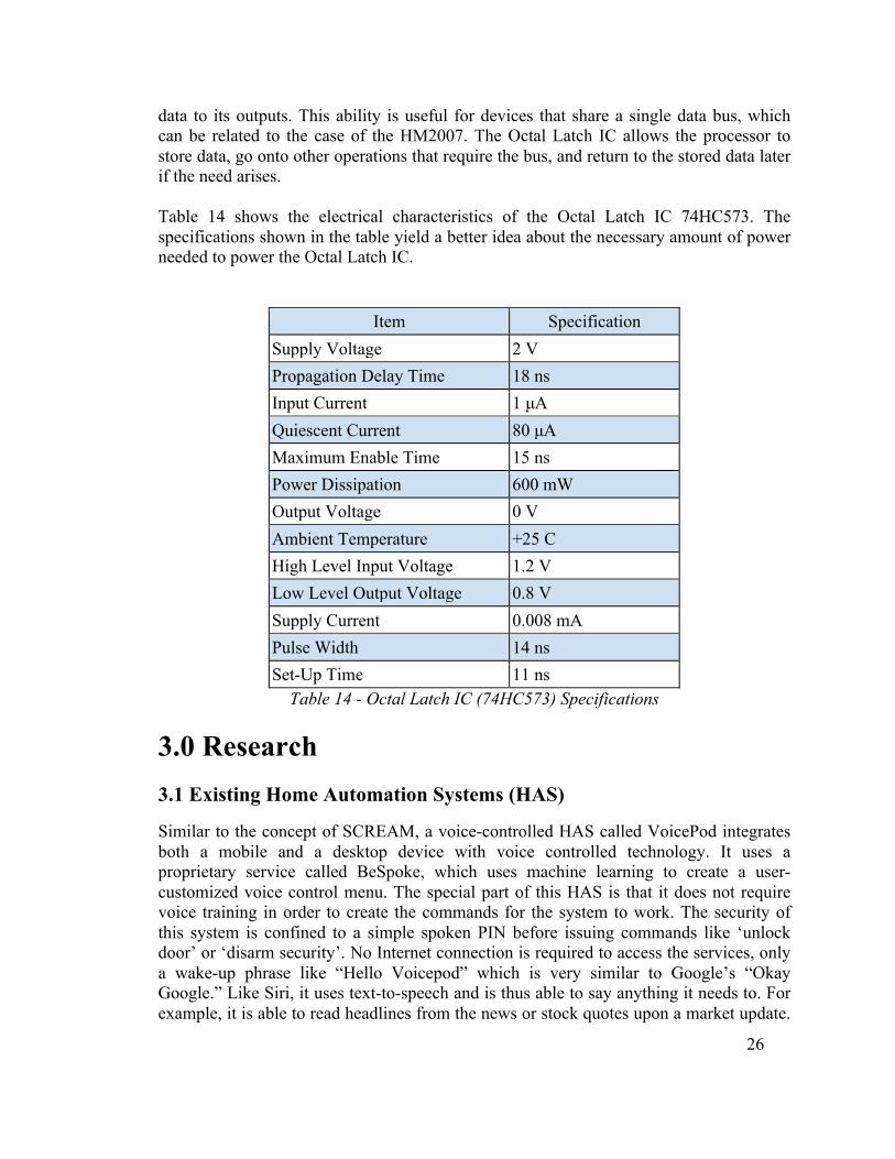
2.3.9.3 Octal Latch IC (74HC573) The Octal Latch IC (74HC573) is high-speed octal D-type latch that is based on advanced silicon-gate P-well CMOS technology. This device possess the high noise immunity and low power consumption of standard CMOS integrated circuits, as well as the ability to drive 15 LS-TTL loads. Due to the large output drive capability and the 3-STATE feature, these devices are ideally suited for interfacing with bus lines in a bus-organized system. When the LATCH ENABLE (LE) input is HIGH, the Q outputs follow the D inputs. When the LATCH ENABLE goes LOW, data at the D inputs are retained at the outputs until LATCH ENABLE returns HIGH again. When a HIGH logic level is applied to the OUTPUT CONTROL OC input, all outputs go to a HIGH impedance state, regardless of what signals are present at the other inputs and the state of the storage elements. The Octal Latch IC must be able to hold onto the data at its inputs before transmitting the
26
data to its outputs. This ability is useful for devices that share a single data bus, which can be related to the case of the HM2007. The Octal Latch IC allows the processor to store data, go onto other operations that require the bus, and return to the stored data later if the need arises. Table 14 shows the electrical characteristics of the Octal Latch IC 74HC573. The specifications shown in the table yield a better idea about the necessary amount of power needed to power the Octal Latch IC.
Item Specification Supply Voltage 2 V Propagation Delay Time 18 ns Input Current 1 µA Quiescent Current 80 µA Maximum Enable Time 15 ns Power Dissipation 600 mW Output Voltage 0 V Ambient Temperature +25 C High Level Input Voltage 1.2 V Low Level Output Voltage 0.8 V Supply Current 0.008 mA Pulse Width 14 ns Set-Up Time 11 ns
Table 14 - Octal Latch IC (74HC573) Specifications
3.0 Research 3.1 Existing Home Automation Systems (HAS)
Similar to the concept of SCREAM, a voice-controlled HAS called VoicePod integrates both a mobile and a desktop device with voice controlled technology. It uses a proprietary service called BeSpoke, which uses machine learning to create a user-customized voice control menu. The special part of this HAS is that it does not require voice training in order to create the commands for the system to work. The security of this system is confined to a simple spoken PIN before issuing commands like ‘unlock door’ or ‘disarm security’. No Internet connection is required to access the services, only a wake-up phrase like “Hello Voicepod” which is very similar to Google’s “Okay Google.” Like Siri, it uses text-to-speech and is thus able to say anything it needs to. For example, it is able to read headlines from the news or stock quotes upon a market update.

27
Installation of this HAS needs a professional touch – one of the ways the SCREAM system is different. VoicePod has two different system setups, one using ZigBee and one using Wi-Fi. The ZigBee version offers fewer features due to the limited bandwidth of the ZigBee protocol but is able to re-adjust the signal to adapt to changing home conditions and because it works between frequency bands it is resilient to interference and it is thus not prone to dead spots like Wi-Fi. Another voice-controlled HAS technology, CastleOS, debuted on the market in 2012. It established its niche by offering a wide range of interoperability with integrated support of x10, INSTEON, Z-Wave, UPB, WeMo, LightwaveRF, Nest, Sonos, Ecobee, and others without any additional setup. It also implements voice control by using a Microsoft Kinect microphone. Its key features center around a mobile user interface, available on any phone operating system, that is easily changeable and focuses on reducing energy consumption through monitoring and event scheduling. The interface also allows for an adjustment of irrigation by the amount of rainfall expected by an independent weather service. The Jasper Project is another voice-controlled HAS that is modeled after J.A.R.V.I.S made popular in the Ironman movies. Jasper uses also uses speech-to-text and text-to-speech using Pocketsphinx and eSpeak in order to understand voice commands and speak to the user, respectively. It uses a Raspberry Pi as a controller and a wireless module to allow both Ethernet and wireless communications. Jasper integrates Spotify to enable home theater automation and Facebook so that users can check Facebook updates. The software portion of Jasper is modular in nature, allowing developers to create their own voice commands using an open source developer API, Phonetisaurus, and CMUCLMTK. The Jasper Project uses cheap parts that, when used together, form a powerful voice controlled HAS. HAL, or Home Automated Living, uses a PC or home server to control a home. Unlike other voice control technologies, however, HAL requires a user to use a phone, press the # key, and then issue a voice command. Unlike CastleOS, HAL provides a response when the command has been completed or was unable to be completed. The user interface is confined to a web application with an instant messaging option. HAL allows for ‘room scenes’ or a set of room configurations that saved and accessed with user key phrases. It also provides morning wake up calls, music suggestions, stock market notifications, and caller ID. The company is more open about user projects than the previous technologies as it welcomes users to provide their personal project details to share with its other users. Recent wireless technologies have caused smart houses, green buildings, and other associated home automation systems to fully realize their potential. 3.2 Technologies Applicable to a HAS
3.2.1 ZigBee
ZigBee, based on an 802.15 standard, uses AES 128 symmetric encryption keys which are important for maintaining physical access security. ZigBee defines a security toolbox

28
for key generation and distribution that can support multiple modes for residential, commercial, and even industrial applications. Conceived in 1998 but standardized in 2003 by IEEE, ZigBee is a freely (for non-commercial purposes) available standard typically used in low power, low latency, and low data rate (less than 250 kbit/sec) applications that require secure networking. It is designed to be simpler and less expensive than Bluetooth or Wi-Fi. Lastly, the ZigBee standard uses a mesh network to route traffic, which would be beneficial if a household has several ZigBee enabled devices. The mesh network is also a way to minimize the 10 meter line-of-sight limitation. If there are multiple devices in multiple rooms, a device in one room would use the mesh network to transmit a signal through other ZigBee devices until the signal reaches the destination. ZigBee operates in the 2.4 Ghz band for most countries worldwide, but for Australia and the United States, Zigbee operates at 915 Mhz. Unfortunately, it shares this band with Bluetooth, Wi-Fi, and other radios. It operates mostly in the physical and media access control layer, but includes a network layer, application layer, ZigBee device objects (ZDOs), and application objects. The network layer is responsible for routing, broadcasting requests, and processing received messages. The application later is the layer responsible for key establishment and propagating changes to a device across a network. ZDOs are responsible for keeping track of device roles, device security, and managing network requests. Application objects allow for customization.
There are three types of ZigBee devices. The ZigBee Coordinator (ZC) is the root of the network tree. It can bridge to other networks. It acts as the Trust Center for security keys and is generally the first device on the network. The ZigBee Router (ZR) is both a host for a running application as well as an intermediate router for other devices on the mesh network. The ZigBee End Device (ZED) is similar to a network node but it cannot relay data from other devices. ZEDs also have the longest battery life due to an increased amount of time in an idle state and can communicate with either a ZC or a ZR. ZigBee devices, as they work in a mesh network, are subject to similar security concerns as ad hoc networks. Trust is assumed in the initial installation and processing of the keys and applications that use the same ZigBee transceiver are assumed to be trustworthy. Any layer within the ZigBee stack is responsible to maintaining its own security and access control within the layer. If used for the purposes of SCREAM, preinstalled keys would be preferred to establishing keys on the fly. This imposes a limitation of an inability to add new trusted devices to the preexisting network, but increases security by mitigating the chance of attack that could happen when adding a new device to the network and establishing trust. Simulating a ZigBee implementation is possible on network simulators like NS2, OPNET, and NetSim. 3.2.2 x10
X10 is a more mature standard developed in 1975. The benefit to using this standard is how inexpensive the components are due to how long the standard has been available. The protocol uses household electrical wiring to transmit data between x10 enabled devices. Data is encoded onto a 120 kHz carrier and a single bit is represented by a one

29
ms burst of 120 kHz transmitted during the zero crossing of the 60 Hz AC waveform. To meet the spirit of SCREAM, however, the radio transmission delineation of the x10 protocol would be more ideal to allow the use of wireless switches. The x10 radio protocol operates at a frequency of 310 Mhz in the United States. A radio receiver then provides a bridge to translate the radio packets into the normal electrical wiring based packets. But even normal packets are transmitted at an agonizingly slow data rate of 20 bits/sec or about 0.75 seconds to transmit a device address and a device command. This is a serious data rate transmission constraint and would limit the features that SCREAM is trying to implement and in order to use x10 the protocol those features would have to be limited to merely turning on or off a device. The dimming of lights can be performed, but due to the speed of the protocol the lights would dim in stages, which would be both noticeable and annoying. In addition, x10 is susceptible to external noise from devices requiring an additional noise-filtering component to prevent spurious on or off signals. As far as security is concerned, not only does the protocol lack support for encryption but also interference is likely if an RF to power line device is used near the system. 3.2.3 Z-Wave
A newer technology that is reflected in its wider range of capabilities, Z-Wave is a proprietary wireless standard that was purchased by Sigma Designs in 2008. As such, it is not an open standard which has resulted in a relative scarcity of Z-Wave IC manufacturers when compared to ZigBee. Z-Wave transmits small packets up to 100 kbit/sec and operates at 908.42 MHz in the United States. This allows it to avoid the crowded 2.4 GHz ISM band and as such it avoids interference with Bluetooth and Wi-Fi but it can still compete with some types of cordless phones. Despite its proprietary nature, Z-Wave does have a community for hobbyists interested in HASs, like Open-zwave, which could be beneficial to implementing SCREAM. Z-wave networks are limited to 232 nodes – which is more than enough for most residential HASs. A Z-Wave network consists of two types of nodes, a controller node and a slave node, and similar to ZigBee, it also allows data packets to travel up to 4 hops between nodes on the network (also mitigating the line-of-sight limitation) and can interface with GPIO, SPI, UART, and PWM on the Sigma Designs ZM3102 module. As an improvement on the ZigBee standard, Z-wave has an increased transmission range of 30 meters, up from 10 meters on ZigBee, between nodes. Key pairing needs to occur when each node is in its final intended location. The Z-wave protocol also includes some security features. For example, it includes a way to use standard 128-AES encryption for pairing. But like most wireless technologies using packets (like ZigBee) it is possible to sniff encryption keys when initializing the devices and it is possible to inject packets. Both ZigBee and Z-wave are searchable through Shodan, an Internet of Things search engine, and have security exploits that have been presented to the public.

30
3.2.4 EnOcean
EnOcean is primarily intended for professional building automation systems, vice HASs, but it is flexible enough to be applied to residential purposes as well. It is also a relatively new protocol developed in 2012. EnOcean modules are intended to perform without batteries as they are designed for energy-scavenging systems. It also uses small packets to transmit data at 125 kbits/sec by transmitting RF energy to symbolize a 1 and transmitting nothing for a 0. The protocol transmits at a distance of 30 meters like Z-Wave, but it does not have the open source communities that Z-Wave and ZigBee have. Security is not addressed by this protocol, so any security contributions would have to implemented separately. 3.2.5 INSTEON
INSTEON is a unique blend of some of the features of x10 and newer mesh networking technologies like ZigBee and Z-Wave. It is like x10 in that data is transmitted over a physical layer that utilizes a home’s existing electrical wiring but can also be transmitted wirelessly via RF technology. Every INSTEON device is a peer on a peer-to-peer network and autonomously transmits, receives, and repeats messages and thus does not require a controlling device. The protocol also has some error detection and correction similar to the Transmission Control Protocol (TCP). Adding a device to an INSTEON network requires “Tap-and-Tap” linking where a user locally manipulates the device to form a device-to-device control link where each device has its own unique ID. Like EnOcean, security is more of an afterthought than a core feature. 3.2.6 Bluetooth
Bluetooth is a twenty-year-old communication standard operating in the popular 2.4 to 2.486 GHz Industrial, Scientific, and Medical (ISM) band. It was standardized as IEEE 802.15.1 but the standard is now considered outdated. The protocol divides packets across a set number of channels. For Bluetooth there are 79 channels. For Bluetooth 4.0 there are 40 channels. It uses Frequency-hopping spread spectrum (FHSS) to transmit radio signals by switching across the 79 (original Bluetooth) or 40 channels (newer versions of Bluetooth) using a pseudorandom sequence known by the transmitter and receiver. A Bluetooth network consists of a master device and up to seven slave devices, but roles between devices can be switched. Switching communication to slave devices is done in a round robin fashion. The original version of Bluetooth allows for data transmission rates of up to 80 kbits/sec, but newer versions improve on this speed. It offers modest error correction using forward error correction. Security is implemented in the pairing, or bonding, process between two devices. The two devices share a link key that is stored by both devices. Communication only occurs between bonded devices when the link key can be cryptographically authenticated. Legacy pairing is available for Bluetooth 2.0 and prior devices. Legacy pairing is where each device must share a PIN code and communication can only occur when two devices have the same PIN code. Bluetooth headsets are limited input devices that have a

31
hardcoded 4-digit PIN. Encryption is not required and can be turned off for these devices. Secure Simple Pairing (SSP) is available for Bluetooth 2.1 and later devices. SSP is similar to public key cryptography and can prevent man in the middle attacks. To maximize security protection, Bluetooth 2.1 and later should be used. It is very similar to Wi-Fi but Bluetooth was intended to connect portable devices. Due to the popularity of Bluetooth devices, particularly Bluetooth headsets, SCREAM would likely benefit from using a Bluetooth headset with a USB dongle due to the decreased cost. The microcontroller would need to have a method of receiving voice commands via the Bluetooth dongle and would need to route them to the voice control chip. Due to the hard-coded nature of the PIN, the headset would be easier to pair but also easier to exploit. It is also possible to use a third party device, such as an iHome Bluetooth connector that allows an Android phone to connect to it. This has an audio out that can be plugged into the main module. 3.2.7 IPv6 Low power Wireless Personal Area Networks (6LoWPAN)
A relatively new protocol created in 2011, 6LoWPAN is intended to apply the Internet Protocol (IP) to the smallest, lowest-power, and most limited processing power Internet of Things (IoT) devices. It was formalized under RFC 6282 and defines an adaptation between the 802.15.4 link layer and a TCP/IP stack using IPv6. It operates using mesh network topologies, similar to ZigBee and Zwave, but there is no standard organization or alliance of organizations that certifies 6LoWPAN compliant devices, therefore different 6LoWPAN devices may or may not be interoperable on a local network. There are two security modes defined in the standard: Access Control List and Secure mode. This protocol is likely too recent to have a large open source community or maker community, which would likely be troublesome during prototyping. 3.2.8 Wi-Fi, Wi-Fi Direct, Wi-Fi Peer-to-peer (P2P)
Wi-Fi is a wireless technology developed in 1997 with the release of the first version of the 802.11 protocol. It operates in the crowded 2.4 Ghz ISM band and is the standard protocol for a large spectrum of devices such as PCs, video game consoles, smartphones, and tablets which could present a problem in terms of possible sources of interference. Wi-Fi offers a range of 66 feet indoors at speeds of at least 1 Mbit/sec but offers a higher power consumption, which could present a problem to maintaining battery life. This protocol requires the use of an access point (AP) that has an Internet connection. Typically, APs default to open mode that does not provide any encryption. Wi-Fi has a few provisions for security, including some archaic methods that should not be used because they are no longer considered secure (Wired Equivalent Privacy or WEP and Wi-Fi Protected Setup). Wi-Fi Protected Access II (WPA2) uses Counter Mode Cipher Block Chaining Message Authentication Code Protocol (CCMP), an enhanced data cryptographic encapsulation using Advanced Encryption Standard (AES), and is considered secure as long as a strong password is used. Wi-Fi Direct does not require a wireless access point in order to operate but does not

32
sacrifice the speeds that normal Wi-Fi is capable of. A Wi-Fi Direct device has a software access point, or Soft AP, embedded into it. That is, no router is required because Wi-Fi Direct establishes an ad-hoc network where devices can communicate via a one-on-one connection or a group of devices can connect simultaneously. This part of the Wi-Fi standard, certified by the Wi-Fi Alliance, ensures that no Internet connection is required to connect devices utilizing Wi-Fi Direct. It also allows WPA2 connections, so there is no sacrifice of security to use it. Pairing can be done by pressing buttons, using a PIN code, using a QR code, or using a near field connection (NFC) to sync connections between devices. It can also be done via a Bluetooth signal, which may make it possible to pair the hands-free microphone to the SCREAM MCU without having to add an additional Bluetooth receiver. It is also possible to know what kinds of devices are available on the network without adding any additional components. Wi-Fi Direct is compatible with Android devices (since Android 4.0 Ice Cream Sandwich), iPhone5s (via iOS7), and BlackBerry (via OS BB 10.2.1) which could more easily allow a mobile component to be added to the system in later designs. Lastly, more than 6000 devices are Wi-Fi Direct certified and the protocol is forecast to ship in 80 percent of all Wi-Fi enabled devices in 2019. Using this standard makes SCREAM very interconnectable with other Wi-Fi enabled devices. 3.3 Speech Recognition Overview
Speech recognition is a normal part of many American lives whether it be interfacing with an automated help desk, dictating to a computer or smartphone, or controlling the actions of a computer or smartphone vocally. Speech recognition systems fall into two categories, small vocabulary intended for many different users or a large vocabulary intended for few users. Small vocabulary systems are limited to a small number of inputs and commands that are predetermined, like a basic menu option or choosing a number from that menu. Small vocabulary systems can understand a larger number of users regardless of accents, due to the smaller amount of the words used. Larger vocabulary systems, however, are intended for use by a smaller group of people due to the lower accuracy rate. The lower accuracy rate comes from the decreased amount of recognition that comes with using larger phrases. There are discrete voice recognition systems that process words with a small pause between each word, but most prefer a continuous speech system that recognizes speech that occurs continuously or flowingly because it sounds conversational in nature. Acoustical vibrations in the air caused by speech are sent to an analog-to-digital converter that translates the analog signal to a digital signal. This is done by sampling the acoustic wave at precise and frequent intervals, known as the Nyquist frequency. Unwanted noise is removed by the use of filters. Unwanted noise could be background noise, which would come through as a low rumble, and can be filtered through the use of a low pass filter around 50 Hz or a high pass filter around 15000 Hz. These filters remove frequencies that are not often found within the normal speaking range. The wave could also be normalized for volume. If perhaps the speaker was yelling or the user bumped into an object that caused a peak in the audio waveform, the speech processor would have difficulty recognizing the word intended. Normalizing the level of sound would increase

33
the accuracy of the processor. It is imperative that the user, during voice training the SCREAM system, be aware of their surroundings. They must speak in a quiet environment and speak in a normal tone of voice. Otherwise, the voice recognition system has significantly reduced accuracy when recognizing words. The wave would then be sped up or slowed down in order to match the template of commands saved in the processor. A user could speak faster or slower than what was saved in memory, so changing the speed of the wave could rectify this. The wave is then separated into very small segments in order to match known phonemes in the appropriate language. A phoneme is a representation of the sounds made to conjugate expressions in the language of choice. Phonemes are examined with regards to the phonemes around them. The processor examines a contextual phoneme plot and runs it through a complex statistical model, comparing the phonemes to a library of known words, phrases, and sentences. Once a hit is found, software using this processor could then interpret what command the user was trying to use and act accordingly. Recent speech recognition systems use statistical modeling systems, like the Hidden Markov Model and neural networks, in order to predict what words the acoustical waves represented. These systems are intended to find the word represented regardless of accent, homonym, or enunciation. For SCREAM, however, a vocal network of 60,000 words requires too much computational power to be acceptable for the embedded world. Speech recognition is classified into two categories, speaker dependent and speaker independent. Speaker dependent systems are trained by the individual who is using the system. These systems are capable of achieving a high command count and better than 95% accuracy for word recognition. The drawback to this approach is that the system only responds accurately only to the individual who trained the system. This is the most common approach employed in software for personal computers. Speaker independent is a system trained to respond to a word regardless of who speaks. Therefore the system must respond to a large variety of speech patterns, inflections and enunciations of the target word. The command word count is usually lower than the speaker dependent however high accuracy can still be maintained within processing limits. Industrial requirements more often need speaker independent voice systems, such as the AT&T system used in the telephone systems. Speech recognition systems have another constraint concerning the style of speech they can recognize. They are three styles of speech: isolated, connected and continuous. Isolated speech recognition systems can just handle words that are spoken separately. This is the most common speech recognition system available today. The user must pause between each word or command spoken. The speech recognition circuit is set up to identify isolated words of 0.96-second lengths. Connected is a halfway point between isolated word and continuous speech recognition. Allows users to speak multiple words. Continuous is the natural conversational speech we are use to in everyday life. It is extremely difficult for a recognizer to sift through the text, as the words tend to merge together. Continuous speech recognition systems are on the market and are under continual development.

34
3.4 Components Needed to Implement SCREAM
3.4.1 Input Module
In order for SCREAM to control devices, the commands to the system must be received. A user controls the system vocally using a microphone. The microphone can be a headset or a wireless Bluetooth device provided that the device is able to connect to the audio port located on the master module. Of the devices researched for the SCREAM system, the Plantronics M55 was the most appealing for a headset. It provides the needed amount of roaming, talk time, standby time, and is below the budgeted amount for the headset. 3.4.2 Access Point or Master Module
The main module is made up of an ODROID-C1 that integrates with the custom speech recognition circuit. The ODROID-C1 has a Wi-Fi dongle installed that provides SCREAM with a wireless transceiver to communicate with the other SCREAM modules. A printed circuit board holds the speech recognition unit. This unit is connected to the ODROID-C1’s GPIO via wiring and this allows the speech recognition chip to process vocal commands and relay them to the ODROID. The ODROID relays commands to outlying units via the wireless dongle. 3.4.3 Light Control Module
A CC3200 is used to receive commands from the access point. A TMP power relay implements the on/off function for the light module, which performs this task at the behest of the ODROID’s wireless dongle. The contacts of the power relay are connected to CC3200, the wall outlet power source, and the light. When a user speaks a command the access point transmits this command wirelessly to the transceiver on the CC3200. Once the command is received, the CC3200 emits a high electrical signal to the relay. The high electrical signal activates the relay and makes the switch of the poles. After the switch is made, the relay allows the power from the outlet wall go through it. The power coming from the outlet wall going through the relay contact turns on the light until the user speaks the command to turn off the light. The off command makes the transceiver send a low electrical signal, which makes the relay poles to switch back to its original position blocking the power source for the outlet. This is diagrammed visually in figure 1.
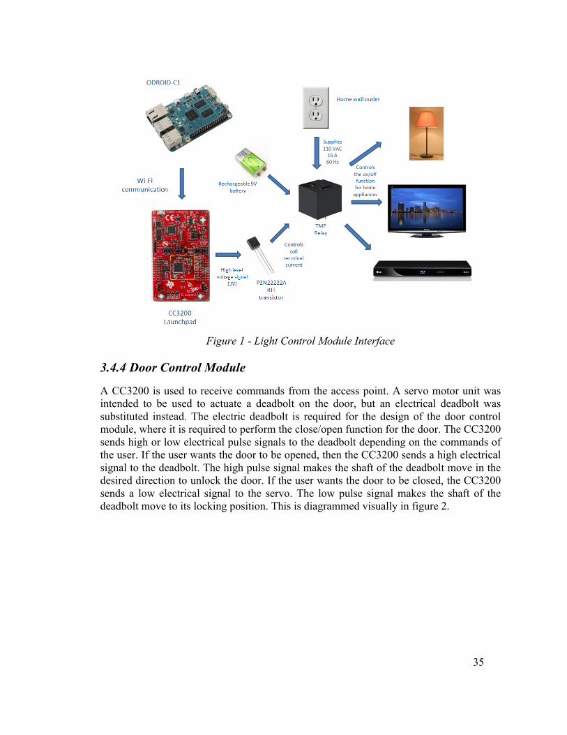
35
Figure 1 - Light Control Module Interface
3.4.4 Door Control Module
A CC3200 is used to receive commands from the access point. A servo motor unit was intended to be used to actuate a deadbolt on the door, but an electrical deadbolt was substituted instead. The electric deadbolt is required for the design of the door control module, where it is required to perform the close/open function for the door. The CC3200 sends high or low electrical pulse signals to the deadbolt depending on the commands of the user. If the user wants the door to be opened, then the CC3200 sends a high electrical signal to the deadbolt. The high pulse signal makes the shaft of the deadbolt move in the desired direction to unlock the door. If the user wants the door to be closed, the CC3200 sends a low electrical signal to the servo. The low pulse signal makes the shaft of the deadbolt move to its locking position. This is diagrammed visually in figure 2.

36
Figure 2 - Door Control Module Interface
3.5 Possible Architectures and Related Diagrams
3.5.1 Microcontroller
3.5.1.1 MSP430 + Zigbee The initial design of SCREAM used a MSP430 to process data in conjunction with a Zigbee module that would handle the wireless communication. The processor would communicate to the Zigbee module through the Universal Asynchronous Receiver Transmitter (UART). The limitations of the design included a low range on the wireless communication subsystem. Additionally having a processor and an external communication circuit would take up more hardware space then having a single chip that could handle both processing and communication.
3.5.1.2 CC3200 The CC3200 is a product made by Texas Instruments that combines a microcontroller and a Wi-Fi communication system into a single chip. It has an ARM Cortex-M4 MCU with on-chip wireless Internet and security protocols. Running at 80MHz and having on-

37
chip RAM and ROM make the CC3200 an ideal candidate for the project. Using Wi-Fi allows communication to remote chips in a wider area throughout the household and having all of these capabilities on a single chip reduces the space requirements.
3.5.1.3 MSP430 + Sub 1GHz Another communication option available while using the same MSP430 microcontroller is to use a communication booster pack. Texas Instruments makes a CC110L RF Booster Pack which can be easily added on to a development board. The boosterpack operates in the 902 - 928 MHz ISM bands and can be controlled using their software application, the AIR BoosterStack. Each of the extension kits are transceivers so they can both send and receive data. Using frequency attenuation can enable a single transmitter to operate with multiple receivers. Booster packs do require the use of some GPIO pins, but there would still be adequate pins available.
3.5.1.4 ODROID-C1 The ODROID-C1, developed by Hardkernel, is a Raspberry Pi derivative built with an ARM Cortex-A5 Quad-core CPU and Mali450MP2 GPU. Although the RAM is the same, 1 GB, the ODROID’s RAM is clocked at twice the speed. It consumes less power at 0.5A versus 0.8A. There is also Android support for the ODROID-C1 which is not available on the Raspberry Pi platform. It performs much better at moving data between a USB drive to the network thanks to its Gigabit Ethernet. Arch Linux is available on this platform through an ARM distribution. Arch Linux is a lightweight customizable Linux distribution that would allow this board to be configured as an access point. Wi-Fi is available through the use of a separate dongle attached to one of the ODROID’s four USB 2.0 ports. Linux drivers must be installed in order for this functionality to occur. There are other, more advanced, versions of the ODROID. Due to cost and need, however, these boards provide more processing power than is necessary, are more expensive, and use more power than the base unit. The ODROID has a 5 V, 2 A power input and uses discrete DC-DC converters and an NCP372 for power protection. It provides 5, 3.3, and 1.8 volt outputs, has 19 available GPIO pins as well as several specialized ones, which are all available on a 20x2 pin header. Adequate GPIO pins are available for the purposes of SCREAM. GPIO experimentation is made easier with the availability of a GPIO breakout board. 3.5.2 Speech Recognition
3.5.2.1 Android The Android Software Developers Kit has built in libraries and an API designed for speech recognition. The use of this kit in an embedded environment would involve the use of an open source operating system that would likely be a Linux platform. The addition of an operating system introduces a new set of challenges. They are slower than a system running without one and require overhead during power up and data transfers. Additionally, the speech recognition would still not happen on chip. Android SDK uses

38
servers owned by Google to process the data and therefore would require access to Wi-Fi. Third party servers can have unpredictable congestion and this latency is undesirable for real time speech recognition. An alternative approach would be to use the speech recognition that is built into Android smartphones. This has similar drawbacks as the aforementioned design but would allow SCREAM to run without an OS. A problem with this option would be the additional hardware that would be required, as the user would have to own or buy and an Android phone to use this product. Application development on the Android platform would also result in additional costs for licensing.
3.5.2.2 HM2007 The HM2007 is a single chip CMOS voice recognition LSI circuit with on chip analog voice analysis and recognition. Using the standard 64K SRAM a maximum of 40 words each up to 0.96 seconds in length can be trained. Alternatively 20 words up to 1.92 seconds in length can be configured. Using an external microphone and keyboard, the microprocessor can store the voice data of these commands that can later be recognized as matching words. There circuit has a response time less than 300 ms and can operate with a single 5 V power supply. It supports two control modes, manual and CPU. SCREAM would use CPU mode in conjunction with a microprocessor that would handle processing and relaying the communication to the remote stations.
3.5.2.3 Windows All Windows operating systems after Vista have preinstalled voice recognition software. It supports over a dozen languages that would increase the potential market for SCREAM. The software allows the user to train the software to their style of speaking which helps solve the problem of words not being recognized due to accents. It is also equipped with means to compensate for different microphone configurations and room acoustics. The drawback of using Windows OS is that it would not allow the product to be a self-contained embedded system and would rely on the use of an additional computer to operate. This would increase the cost due to the additional processing and memory requirements to run and maintain a Windows platform and the size of SCREAM would increase to enclose all the additional system components. 3.6 Servo Control System
Servo control systems are the most important and widely used forms of control systems. Any piece of equipment that has rotating parts contains one or more servo control systems. A servo system mainly consists of three basic components, which are a controlled device, an output sensor, and feedback system. This servo system is an automatic closed loop control system. Instead of controlling a device by applying a variable input signal, the device is controlled by a feedback signal generated by comparing output signal and reference input signal. The servo system takes a command signal, which is issued from the user’s interface panel and comes into the servo’s positioning controller. The positioning controller is the device,

39
which stores information about various jobs or tasks. It has been programmed to activate the motor/load (change speed/position). The signal then passes into the servo control or amplifier section. The servo control takes this low power level signal and increases, or amplifies, the power up to the appropriate levels to actually result in movement of the servo motor/load. These low power level signals must be amplified. Higher voltage levels are needed to rotate the servo motor at appropriate higher speeds and higher current levels are required to provide torque to move heavier loads. This power is supplied to the servo control (amplifier) from the power supply, which simply converts AC power into the required DC level. It also supplies any low level voltage required for operation of integrated circuits. As power is applied onto the servo motor, the load begins to move and the speed and position changes. As the load moves, another device moves. This other device is either a tachometer, a resolver or an encoder (providing a signal which is sent back to the controller). This feedback signal is performing the positioning controller whether the motor is doing the proper job. The positioning controller looks at this feedback signal and determines if the load is being moved properly by the servo motor; and, if not, then the controller makes appropriate corrections. For example, assume the command signal was to drive the load at 1000 rpm. For some reason it is actually rotating at 900 rpm. The feedback signal informs the controller that the speed is 900 rpm. The controller then compares the command signal (desired speed) of 1000 rpm and the feedback signal (actual speed) of 900 rpm and notes an error. The controller then outputs a signal to apply more voltage onto the servo motor to increase speed until the feedback signal equals the command signal, i.e. there is no error. Therefore, a servo involves several devices. It is a system of devices for controlling some load. The load, which is regulated, can be controlled in any manner, position, direction, and speed. The speed or position is controlled in relation to a reference (command signal), as long as the proper feedback device (error detection device) is used. The feedback and command signals are compared, and the corrections made. Thus, the definition of a servo system is that it consists of several devices, which control or regulate speed/position of a load. 3.6.1 Servo Motor Control
A servo motor is basically a DC motor along with some other special purpose components that make a DC motor a servo. A servo unit contains a small DC motor, a potentiometer, gear arrangement and an intelligent circuitry. The intelligent circuitry along with the potentiometer makes the servo to rotate according to the user commands. A small DC motor rotates with high speed, but the torque generated by its rotation is not enough to move even a light load. This is where the gear system inside a servomechanism comes into play. The gear mechanism takes the high input speed of the motor and at the output there is an output speed, which is slower than original input speed, but more
40
practical and widely applicable. At the initial position of the servo motor shaft, the position of the potentiometer knob is such that there is no electrical signal generated at the output port of the potentiometer. This output port of the potentiometer is connected with one of the input terminals of the error detector amplifier. Now an electrical signal is given to another input terminal of the error detector amplifier. The difference between these two signals, one from the potentiometer and another from an external source, is amplified in the error detector amplifier and feeds the DC motor. This amplified error signal acts as the input power of the DC motor and the motor starts rotating in desired direction. As the motor shaft progresses the potentiometer knob also rotates as it is coupled with motor shaft with help of gear arrangement. As the position of the potentiometer knob changes there is an electrical signal produced at the potentiometer port. As the angular position of the potentiometer knob progresses the output or feedback signal increases. After the desired angular position of motor shaft the potentiometer knob reaches at such position the electrical signal generated in the potentiometer becomes same as the external electrical signal given from the amplifier. In this condition, there are no output signals from the amplifier to the motor input as there is no difference between the external applied signal and the signal generated at the potentiometer. As the input signal to the motor is nil at that position, the motor stops rotating.
4.0 Hardware and Software Design Details 4.1 Power Supplies
The design of the power supply for each subsystem of SCREAM consists of using an AC/DC converter mobile charger, 9V batteries, AA batteries and a 12V Li-ion rechargeable battery. The main power supply of SCREAM is the AC/DC converter, which is in charge to supply the required 5 VDC to the ODROID-C1. For the AC/DC converter, an AC/DC wall power charger adapter for an Android tablet was used as the main power supply for the ODROID-C1. For the purpose of simplicity of the power supply design, the wall charger adapter device is the best choice due to its cost, availability and electrical characteristics.. The wall charger adapter always gives the required constant DC voltage, which means that the user does not have to worry about having the system to shut off for a lack of voltage discarding the idea of constantly changing batteries The SRC (HM2007) requires a total power amount of 1.5W in order to operate. The ODROID-C1 supplies 5VDC through one of its I/O pins to the SRC. Each of the CC3200 launchpads uses two AA batteries as power supplies. The two double AA batteries supply 3VDC to the CC3200, which will set the output voltage from the GPIO pins to be the same as the input. This is not a sufficient amount of voltage that is needed in order to activate the TMP relays and the electric deadbolt. One solution was using op amps to amplify the signal, but power switching transistors were used instead.

41
The P2N2222A transistor is used to control the current flow from the 9V battery. The 9V battery is used to set the TMP relay to active mode when is needed. Similarly, the TIP120 Darlington transistor is used with the same purpose to control the current flowing from a 12V 3800mAh Li-ion rechargeable battery. The Electric deadbolt requires 12W of power in order to actuate the bolt. The rechargeable battery has a high amperage capacity of 3800mAh, which is enough power to unlock the deadbolt for multiple times. The rechargeable battery can last for at least 3 hours and 50 minutes of continuous operation. 4.2 Door Control Unit
The CC3200 in the door control unit processes received signals and when necessary applies or removes voltage from GPIO pin 2. This I/O pin is also connected to an onboard LED so a change in status can be noticed even if no electrical device is connected. When a valid command is received, voltage across pins 2 and 20 is applied/removed and a logic level signal is sent to the door control unit (DCU) board. The DCU board is responsible to control the unlock/lock function for the door module. The board size is 2.43x1.49 inch and the PCB is a 2-layer design. The board consists of using a TIP120 NPN Darlington transistor, a 1N4005 rectifier diode, a 390 Ω resistor, a 2.1 mm inside diameter (ID)/5.5mm outside diameter (OD) power jack connector, a two position 3.5 mm pitch terminal block, and a three pin female header power connector. This is diagrammed visually in figure 3.
Figure 3 - Door Unit Diagram
42
The CC3200’s pins 2 and 20 connect to the female header power connector on the DCU board. The female header power connector supplies the high-level voltage signal through the 390 Ω resistor that is connected to the base of the TIP120. A rechargeable 12V battery connects to the collector of the TIP120 with the task to supply 12VDC to the normally open (NO) mode fail-secure electric deadbolt. The 390 Ω resistor is connected to the base to limit the amount of current flowing to the base by 1/250 of the collector current. During saturation mode, the TIP120 operates with a base-emitter junction voltage of 1.5VDC (Vbe(sat)), a collector-emitter voltage (Vce(sat)) of 0.6VDC and the minimum current gain of 250. The CC3200 GPIO supplies the sufficient amount of voltage to the transistor to set into saturation mode. When the CC3200 sends a high level signal, the transistor is in saturation state. During this state the transistor acts as a closed-circuit allowing the current to flow through the solenoid of the electric bolt assembly. When the user does not use system or the CC3200 sends a low signal, the transistor is in cut-off state. During this state the transistor acts as open-circuit interrupting the current flow through the solenoid of the electric bolt assembly. The electric deadbolt consists of the main body that is attached to the door and the magnetic base that is attached to the door frame. The main body dimension is 28 x 200 x39mm and the magnetic base is 25 x 90 x 25mm. The two components are in contact when the door is closed. When the solenoid of the main base is energized, a current passing through the solenoid creates a magnetic flux that causes the magnetic base to interface with the main base, creating an unlocking/locking action. The electric deadbolt uses a timer to control the unlocked position while the door is opened, and the main base and magnetic base are separated. The timer can be set to 0, 3 or 6 seconds. The solenoid of the electric deadbolt has two wires that are connected to the terminal block of the DCU board. One connection of the terminal block is connected to the 2.1mm (ID)/5.5mm (OD) power jack connector. The power jack connector is used in the DCU board as an input connector for the rechargeable 12V battery. The second connection of the terminal block is connected to the collector connection of the TIP120. The rechargeable battery can supply a capacity of 3800mAh, which is plenty enough power to unlock the deadbolt for a few seconds multiple times. 4.3 Relay Control Unit
The CC3200 in the relay control unit processes received signals and when necessary applies or removes voltage from GPIO pin 2. This IO pin is also connected to an onboard LED so a change in status can be noticed even if no electrical device is connected. The CC3200 launchpad operates with two AA batteries, which allows the processor to send a high level signal of 3V and 10.75 mA through pin 2. Pins 2 and pin 20 (GND pin) are applied to send a high/low level voltage signal to the relay control unit (RCU) printed circuit board (PCB). The board size is 3.94x2.03 inch and the PCB is a 2-layer design. The board houses a high power switching TMP relay SPDT type, a P2N2222A bipolar

43
NPN switching transistor, a rectifier diode 1N4005, a 270 ohm resistor, a three pin female header power connector, and rechargeable 9 Volt Lithium Polymer Battery. This is diagrammed visually in figure 4.
Figure 4 - Light Module Diagram
The CC3200 GPIO (pin 2) and GND (pin 20) pins connect to the female header power connector on the RCU board. The female header power connector supplies the high level voltage signal through the 270 ohm resistor that is connected to the base of the P2N2222A. A rechargeable 9V battery connects to the collector of the P2N2222A with the task to supply 9VDC to the relay. The 270 Ω resistor is connected to the base to limit the amount of current flowing to the base by 1/10 of the collector current. The P2N2222A transistor operates in two states, which are cutoff and saturation. Using the two states, the transistor may be used as a current control switch. The collector and emitter are the switch terminals and the base is the switch handle. In other words, the small base current can be made to control a much larger current between the collector and emitter. The saturation state happens when the base-emitter and base-collector junctions are forward bias. In addition, the effective resistance between collector and emitter in saturation state is small, making the transistor to act as a closed- circuit. During saturation mode, the P2N2222A operates with a base-emitter junction voltage of 0.85VDC (Vbe (sat)), a collector-emitter voltage (Vce (sat)) of 0.1VDC and the minimum current gain of 10. The CC3200 GPIO supplies the sufficient amount of voltage to the transistor to set the two junctions to be forward bias. When the CC3200 sends a high level signal, the transistor is in saturation state. During this state the transistor acts as a closed-circuit allowing the current to flow to the coil of the relay. When the user does not use system or

44
the CC3200 sends a low signal, the transistor is in cut-off state. During this state the transistor acts as open-circuit interrupting the current flow to the coil of the relay. The high power switching TMP relay is implemented in the system to control the on/off function of the home appliances. The relay is capable to control a maximum switching capacity of 5540W (20A 277VAC) using the normally open (NO) terminal. The relay requires 800 mW (9VDC 89.1mA) of power in order to be functional. The TMP relay is equipped with a drive terminal (coil terminal) on one side, and a load terminal (tab terminal) on the reverse side. The coil terminal uses two bottom pins of the relay and they are directly attached to the RCU board. One pin is connected to the positive terminal of the 9V battery and the other is connected to the collector connection of the P2N2222A transistor. During the switching process the coil of the relay acts as an inductor storing a significant amount of current that could create a high voltage spike and can damage the electronic parts in the unit. The IN4005 rectifier diode is connected across the coil terminal pins. The IN4005 handles the coil current and protects the unit from a high output voltage peak coming from the relay when the system turns off. In addition, there are three tab terminals, which are common (COM), normally closed (NC) and normally open (NO). These tab terminals are located on the topside of the relay. The COM tab terminal is connected to one of the AC wire connections from a power adapter cable. The power adapter cable is used to connect the unit to the AC power coming from a wall outlet. The COM tab transfer the AC power to the NO tab when the relay is on operation mode. The NO tab is wired to a terminal tab connection that is located on the back of power entry connector. The power entry connector is used to connect the relay control unit to any home appliance. 4.4 Main Module Microcontroller - ODROID-C1 The ODROID-C1 was configured using Arch Linux as a software AP. Upon startup, the ODROID-C1 establishes itself as a wireless AP using hostapd, dnsmasq, and iptables on the Arch Linux platform. Hostapd configures the wireless access point, iptables performs traffic routing, and dnsmasq deals with DNS routing and provides DHCP leases. The IP address for the ODROID-C1 uses the reserved address space of 192.168.1.0/24, allowing for up to 100 devices to connect to the AP. Bourne Again Shell (BASH) scripting has been used to automate the setup of these services on startup. Figure 5 below shows the ODROID’s position in the initial version of the enclosure.
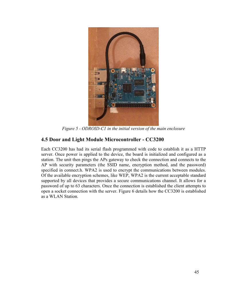
45
Figure 5 - ODROID-C1 in the initial version of the main enclosure
4.5 Door and Light Module Microcontroller - CC3200
Each CC3200 has had its serial flash programmed with code to establish it as a HTTP server. Once power is applied to the device, the board is initialized and configured as a station. The unit then pings the APs gateway to check the connection and connects to the AP with security parameters (the SSID name, encryption method, and the password) specified in connect.h. WPA2 is used to encrypt the communications between modules. Of the available encryption schemes, like WEP, WPA2 is the current acceptable standard supported by all devices that provides a secure communications channel. It allows for a password of up to 63 characters. Once the connection is established the client attempts to open a socket connection with the server. Figure 6 details how the CC3200 is established as a WLAN Station.
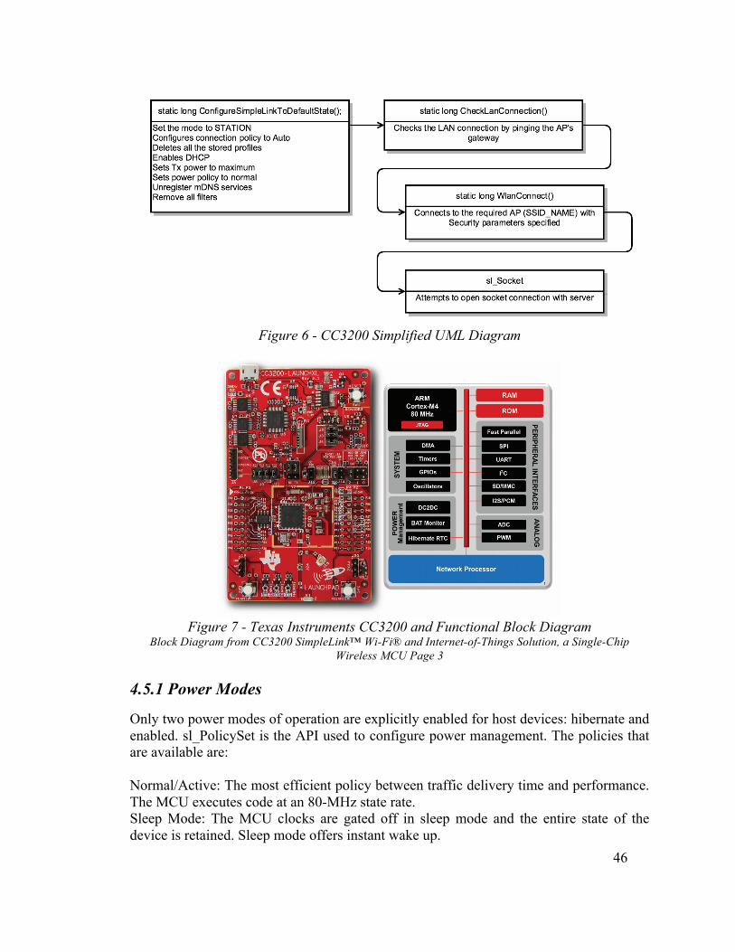
46
Figure 6 - CC3200 Simplified UML Diagram
Figure 7 - Texas Instruments CC3200 and Functional Block Diagram
Block Diagram from CC3200 SimpleLink™ Wi-Fi® and Internet-of-Things Solution, a Single-Chip Wireless MCU Page 3
4.5.1 Power Modes
Only two power modes of operation are explicitly enabled for host devices: hibernate and enabled. sl_PolicySet is the API used to configure power management. The policies that are available are: Normal/Active: The most efficient policy between traffic delivery time and performance. The MCU executes code at an 80-MHz state rate. Sleep Mode: The MCU clocks are gated off in sleep mode and the entire state of the device is retained. Sleep mode offers instant wake up.
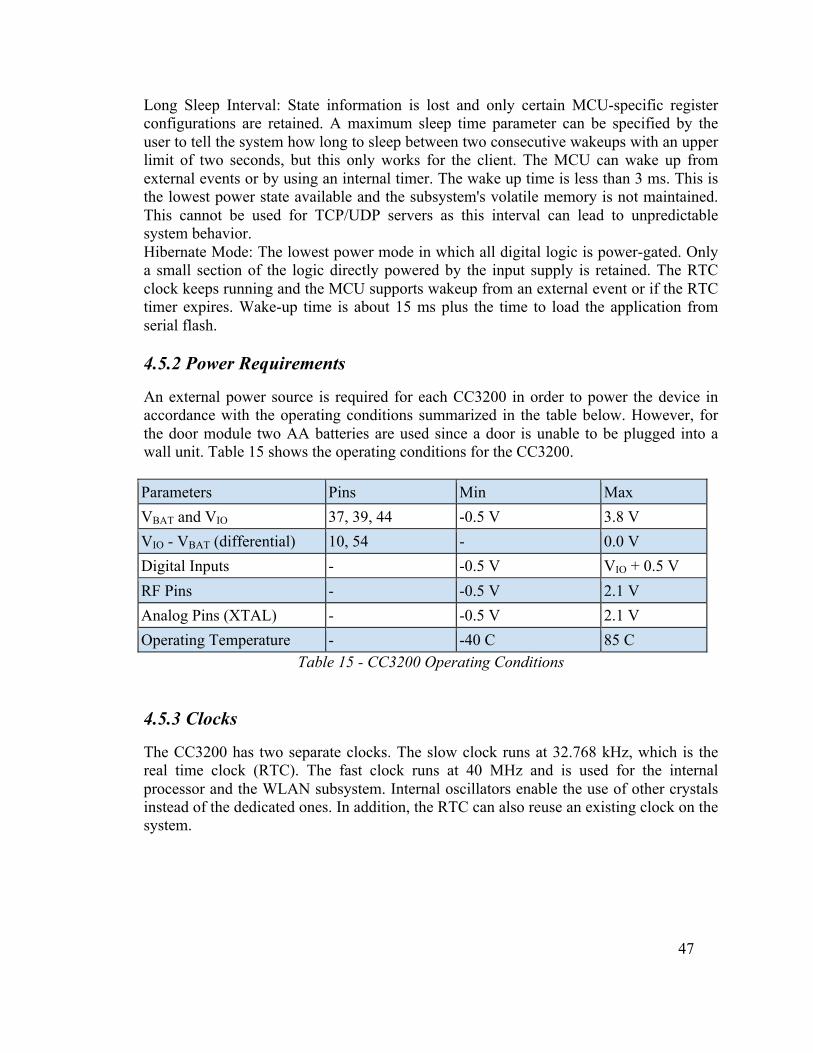
47
Long Sleep Interval: State information is lost and only certain MCU-specific register configurations are retained. A maximum sleep time parameter can be specified by the user to tell the system how long to sleep between two consecutive wakeups with an upper limit of two seconds, but this only works for the client. The MCU can wake up from external events or by using an internal timer. The wake up time is less than 3 ms. This is the lowest power state available and the subsystem's volatile memory is not maintained. This cannot be used for TCP/UDP servers as this interval can lead to unpredictable system behavior. Hibernate Mode: The lowest power mode in which all digital logic is power-gated. Only a small section of the logic directly powered by the input supply is retained. The RTC clock keeps running and the MCU supports wakeup from an external event or if the RTC timer expires. Wake-up time is about 15 ms plus the time to load the application from serial flash. 4.5.2 Power Requirements
An external power source is required for each CC3200 in order to power the device in accordance with the operating conditions summarized in the table below. However, for the door module two AA batteries are used since a door is unable to be plugged into a wall unit. Table 15 shows the operating conditions for the CC3200. Parameters Pins Min Max VBAT and VIO 37, 39, 44 -0.5 V 3.8 V VIO - VBAT (differential) 10, 54 - 0.0 V Digital Inputs - -0.5 V VIO + 0.5 V RF Pins - -0.5 V 2.1 V Analog Pins (XTAL) - -0.5 V 2.1 V Operating Temperature - -40 C 85 C
Table 15 - CC3200 Operating Conditions
4.5.3 Clocks
The CC3200 has two separate clocks. The slow clock runs at 32.768 kHz, which is the real time clock (RTC). The fast clock runs at 40 MHz and is used for the internal processor and the WLAN subsystem. Internal oscillators enable the use of other crystals instead of the dedicated ones. In addition, the RTC can also reuse an existing clock on the system.
48
4.5.4 Peripherals
4.5.4.1 Universal Asynchronous Receiver/Transmitter (UART) Two UARTs are available on the CC3200. Each UART has a programmable baud-rate generator that allows speeds up to 3 Mbps. There are separate transmit and receive FIFOs (of a programmable length) to reduce the strain on the CPU interrupt. The UART has standard line break generation and detection, and standard asynchronous communication bits for start, stop, and parity. The serial interface is fully programmable, allowing for 5 to 8 data bits, an even, odd, or no parity bit generation and detection, and 1 or 2 stop bits. Regardless if there is an OS behind the driver, it supports a simple OS wrapper, sync objects, locked objects, and logic within the driver in the case that the system is not running an OS (like SCREAM).
4.5.4.2 Serial Peripheral Interface (SPI) The CC3200 includes one SPI module that can be configured as a master or slave device. It only supports the use of 4-wire SPI. It can use 8-, 16-, or 32-bit word length in Default mode 0 (CPOL=0, CPHA=0). The SPI clock can be configured up to 20 Mbps. An additional IRQ line is required for asynchronous operations, but should not be required for the purposes of the project. 4.5.5 Memory
The CC3200 device stores a proprietary file system on the SFLASH that contains the service pack file, system files, configuration files, certificate files, web page files, and user files. A format command is available through the API that allows users to access the total size allocated for the file system. The starting address is always located at the beginning of the SFLASH and cannot be changed. The file system API works in plain text but the encryption and decryption subsystems are invisible to users. Encrypted files can be accessed through the file system. Regular files are stored in blocks of 4 KB and use a minimum of 4 KB flash space. Encrypted files take up double the space at a minimum of 8 KB. The maximum file size is 16 MB, which should be plenty of space for SCREAM provided that the code is programmed efficiently. Application programs are downloaded and executed from on-chip SRAM. The SRAM must be used for both code and data. The ROM is available at address 0x0000_0000 and programmed with the bootloader and the peripheral device library. The bootloader is used as an initial program loader when the serial flash memory is empty and the library performs peripheral initialization and control functions. These can be controlled using the DriverLib software provided by TI. 4.5.6 Cortex Processor Boot Sequence
1. After power-on-reset the processor starts execution. 2. The processor jumps to the first few lines of code in the ROM to determine if the

49
current boot is the initialization boot or the second MCU boot. That determination is based on the status of the device-init flag in a secure register. The registers in the secure region are accessible only in the device-init mode. 3. If the current boot is the first boot, the processor executes the device-init code from ROM. 4. At the end of the boot, the processor clears the Device-Init flag and changes the master ID of the processor and the DMA. These registers are part of the secure region. 5. The processor resets itself, initiating a second boot. 6. During the second boot, the processor rereads the Device-Init flag, the bit is cleared, and the processor obtains a different master ID. 7. After executing FFL and the unsecure boot code, the processor jumps to the developer code (application). 8. For the rest of the operation (until the next power cycle), the Cortex mode is designated the MCU. During this phase, access to the secure region is restricted. 4.5.7 Using the CC3200’s Transceiver
The SimpleLink Host driver to run the MCU as an Access Point (AP) requires less than 7KB of flash memory and 700B of RAM for a TCP client application. The driver can run 8, 16, or 32-bit, at any clock speed because there is no time dependency, and can use either big or little endian. To enable the bus interface in the CC3200 SPI is used, for the CC3100, SPI or UART can be used. To enable the Wi-Fi subsystem in the CC3200 the microcontroller must be used, for the CC3100, the external host processor. Unfortunately, the software and programming additional interfaces that use this software have to be ANSI C89 compliant to ensure compatibility. Sockets are formed using the Berkeley socket API. The host driver supports asynchronous event handling because networking commands, like WLAN connection establishment, may take time to process. If this happens, the host gets an Command Complete response followed by an asynchronous event. Asynchronous events signal that the command that took an extended amount of time has finished and signals a process return. Commands between the host driver and the device work as depicted in the following Figure 8.
Figure 8 - Communication Procedure for CC3200 Network Processor Subsystem
Icons made by Freepik from www.flaticon.com is licensed under CC 3.0 Security options for the subsystem are open security, WEP with a 5 to 13 character ASCII password, and WPA with a 8 to 63 character password. For SCREAM, WPA2 is used and not WEP due to the increased security associated with WPA2.
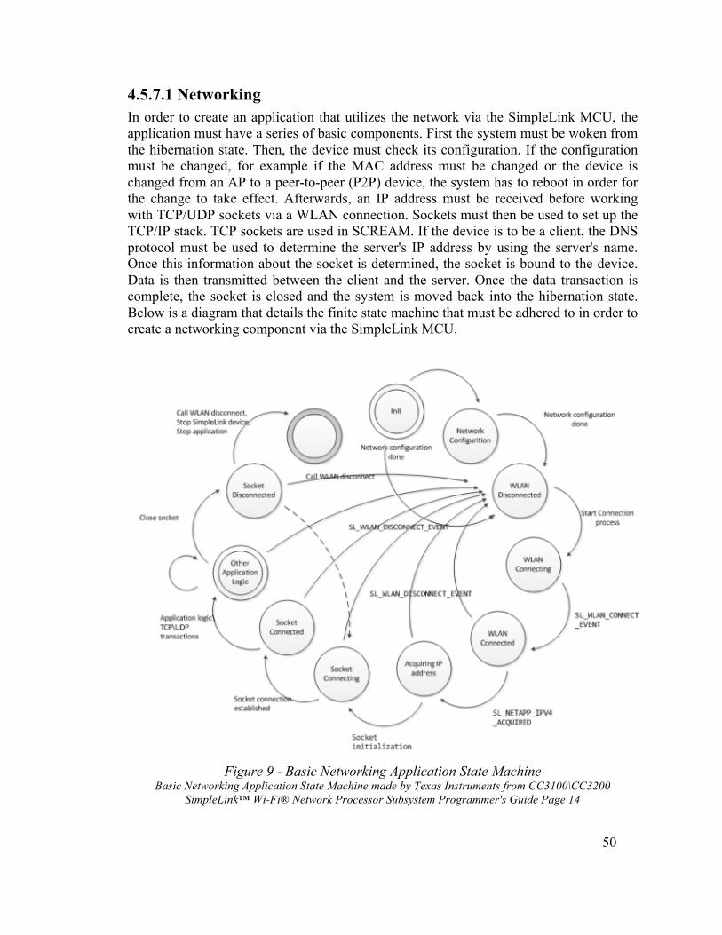
50
4.5.7.1 Networking In order to create an application that utilizes the network via the SimpleLink MCU, the application must have a series of basic components. First the system must be woken from the hibernation state. Then, the device must check its configuration. If the configuration must be changed, for example if the MAC address must be changed or the device is changed from an AP to a peer-to-peer (P2P) device, the system has to reboot in order for the change to take effect. Afterwards, an IP address must be received before working with TCP/UDP sockets via a WLAN connection. Sockets must then be used to set up the TCP/IP stack. TCP sockets are used in SCREAM. If the device is to be a client, the DNS protocol must be used to determine the server's IP address by using the server's name. Once this information about the socket is determined, the socket is bound to the device. Data is then transmitted between the client and the server. Once the data transaction is complete, the socket is closed and the system is moved back into the hibernation state. Below is a diagram that details the finite state machine that must be adhered to in order to create a networking component via the SimpleLink MCU.
Figure 9 - Basic Networking Application State Machine
Basic Networking Application State Machine made by Texas Instruments from CC3100\CC3200 SimpleLink™ Wi-Fi® Network Processor Subsystem Programmer's Guide Page 14

51
4.6 Microphone
The M55 can be a unit that SCREAM can utilize as a headset, but recall that any microphone that can fit the audio port can be used. It has a roaming distance of 33 feet and a battery life that lasts 11 hours for active talk time, on standby the battery life is increased to 16 days, and on the "DeepSleep" mode the time is increased to 150 days which is above the minimum required specification for battery life. The headset provides for noise reduction and echo cancellation that can allow acoustic data to be more easily processed by the speech recognition unit. The cost of the M55 is $50 retail which allows another $20 to purchase a generic Bluetooth 2.1 or above dongle. The first time the headset is turned on it automatically goes into discoverable, or pairing, mode. The indicator light on the headset should flash red-white on the device while in this mode. While charging the light is solid red until it is fully charged. Two hours is required for a full charge. While at very low battery life the indicator light gives three red flashes while powering on. If the headset is out of range from the paired device, DeepSleep mode is available after 90 minutes. To exit this mode, the Call button should be tapped. This unit gives voice alerts to various statuses, but the 'Lost Connection', 'Pairing', 'Pairing Successful', and 'Pairing Incomplete' alerts should be the most useful while troubleshooting the device. 4.7 Speech Recognition
The embedded speech recognition subsystem uses the HM2007 single chip LSI circuit. It features front-end voice analysis, a recognition process and a series of control functions. It uses an external microphone 35mm port as its analog input and uses push button switches and external SRAM to store and recall voice patterns. The chip can be configured to run in manual mode which functions independently of additional control logic or in CPU mode where a microprocessor maintains control. Additionally the memory allows the use of variable length recordings for situational optimization. The integrated circuits diagram and pin descriptions are available in Datasheet: Speech Recognition IC(HM2007) for reference. However the pins needed for operation are described in Table 16 below.

52
Symbol Function S1 Output buffer/Status register selection pin S2 Internal register content placed on K bus S3 K bus content placed in input buffer RDY Low signal when HM2007 is ready for voice input K1-K4 Bidirectional data bus between HM2007 and microcontroller (K bus) WLEN Word length selection pin CPUM CPU mode selection pin WAIT Voice processing skip DEN Data enable signal SA0-SA12 External memory address bus (SA bus) ME Memory enable pin MR/MW Memory read/write select pin D0-D7 External memory data bus (D bus)
Table 16 - Description of HM 2007 Pinout The board was configured and tested in manual mode to insure the proper function of the integrated circuit and peripheral components. To set the board to manual mode the pin CPUM was connected to GND. A diagram outlining the IC, external memory, LCD display and corresponding drivers, and the keyboard are shown below in figure 10.
Figure 10 - HM 2007 IC
Reprinted from Speech Recognition Tutorial with permission of Imagesco Scientific Instruments
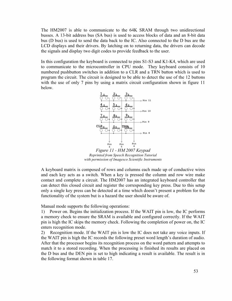
53
The HM2007 is able to communicate to the 64K SRAM through two unidirectional busses. A 13-bit address bus (SA bus) is used to access blocks of data and an 8-bit data bus (D bus) is used to send the data back to the IC. Also connected to the D bus are the LCD displays and their drivers. By latching on to returning data, the drivers can decode the signals and display two digit codes to provide feedback to the user. In this configuration the keyboard is connected to pins S1-S3 and K1-K4, which are used to communicate to the microcontroller in CPU mode. They keyboard consists of 10 numbered pushbutton switches in addition to a CLR and a TRN button which is used to program the circuit. The circuit is designed to be able to detect the use of the 12 buttons with the use of only 7 pins by using a matrix circuit configuration shown in figure 11 below.
Figure 11 - HM 2007 Keypad
Reprinted from Speech Recognition Tutorial with permission of Imagesco Scientific Instruments
A keyboard matrix is composed of rows and columns each made up of conductive wires and each key acts as a switch. When a key is pressed the column and row wire make contact and complete a circuit. The HM2007 has an integrated keyboard controller that can detect this closed circuit and register the corresponding key press. Due to this setup only a single key press can be detected at a time which doesn’t present a problem for the functionality of the system but is a hazard the user should be aware of. Manual mode supports the following operations: 1) Power on. Begins the initialization process. If the WAIT pin is low, the IC performs a memory check to ensure the SRAM is available and configured correctly. If the WAIT pin is high the IC skips the memory check. Following the completion of power on, the IC enters recognition mode. 2) Recognition mode. If the WAIT pin is low the IC does not take any voice inputs. If the WAIT pin is high the IC records the following preset word length’s duration of audio. After that the processor begins its recognition process on the word pattern and attempts to match it to a stored recording. When the processing is finished its results are placed on the D bus and the DEN pin is set to high indicating a result is available. The result is in the following format shown in table 17.

54
D7 D6 D5 D4 D3 D2 D1 D0 Description 0 0 0 0 0 0 0 0 Power ON A B Word AB 0 1 0 1 0 1 0 1 Voice too long 0 1 1 0 0 1 1 0 Voice too short 0 1 1 1 0 1 1 1 No Match
Table 17 - Recognition Mode Format 3) Training mode. To train a pattern the user first has to select which voice pattern number they want to train. To do this they select a two-digit number using the push buttons. Acceptable inputs are number 1-20 if using 0.98 second long recordings or 1-40 if using 1.96-second recordings. Following the two-digit input, the user presses the TRN button. If the WAIT pin is set to low no recording is taken, only when the WAIT pin is set to high does the recording begin. 4) Clear pattern mode. The user enters a two-digit number in the same manner as in training mode. Following the number input, the user presses the CLR button. At this point if the pattern number is valid, the recording is cleared from memory. 5) Clear all patterns. If the number “99” is entered into the keyboard and the CLR is subsequently pressed, the HM2007 clears all voice patterns from memory. This concludes the functions available during manual operation mode. The same operations are available for use during CPU mode with slight modifications and there are additional functions available. To set the IC to CPU mode the CPUM pin must be connected to Vcc. The HM 2007 has three four bit internal registers. A read only status buffer which is used to reflect the IC’s operating state, a read only output buffer register which is used to send results to a microcontroller and a write only input buffer register which is used to receive commands from the microcontroller. The status register uses only its lower two bits to reflect its operating state. The four possible states are outlined in table 18. An external device can poll the K bus to see its state by setting the S2 pin high and the S1 and S3 pins low.
ST3 ST2 ST1 ST0 Operating State X X 0 1 Ready for voice input X X 1 0 Ready for command X X 1 1 First nibble of data is ready X X 0 0 Second nibble of data is ready
Table 18 - Possible States While the HM2007 is in its “Ready for command” state the microprocessor can control its actions. To send the unit a command, the S3 pin must be set high and the S1 and S2
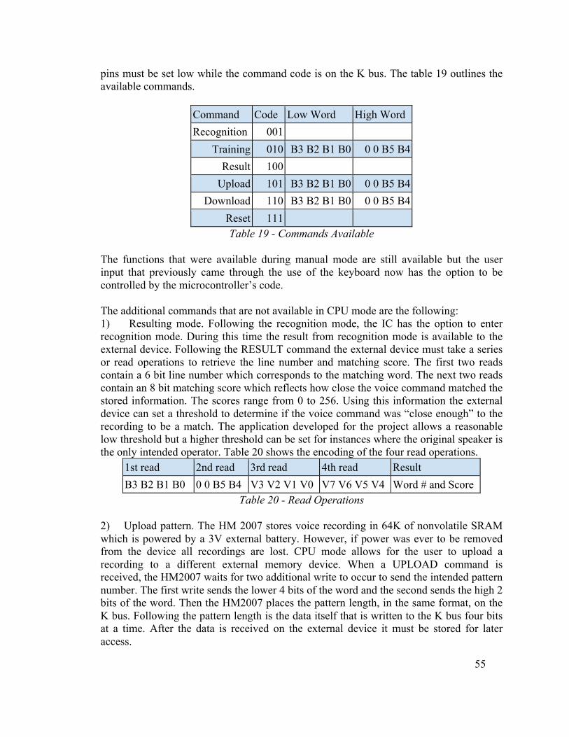
55
pins must be set low while the command code is on the K bus. The table 19 outlines the available commands.
Command Code Low Word High Word Recognition 001
Training 010 B3 B2 B1 B0 0 0 B5 B4 Result 100
Upload 101 B3 B2 B1 B0 0 0 B5 B4 Download 110 B3 B2 B1 B0 0 0 B5 B4
Reset 111 Table 19 - Commands Available
The functions that were available during manual mode are still available but the user input that previously came through the use of the keyboard now has the option to be controlled by the microcontroller’s code. The additional commands that are not available in CPU mode are the following: 1) Resulting mode. Following the recognition mode, the IC has the option to enter recognition mode. During this time the result from recognition mode is available to the external device. Following the RESULT command the external device must take a series or read operations to retrieve the line number and matching score. The first two reads contain a 6 bit line number which corresponds to the matching word. The next two reads contain an 8 bit matching score which reflects how close the voice command matched the stored information. The scores range from 0 to 256. Using this information the external device can set a threshold to determine if the voice command was “close enough” to the recording to be a match. The application developed for the project allows a reasonable low threshold but a higher threshold can be set for instances where the original speaker is the only intended operator. Table 20 shows the encoding of the four read operations.
1st read 2nd read 3rd read 4th read Result B3 B2 B1 B0 0 0 B5 B4 V3 V2 V1 V0 V7 V6 V5 V4 Word # and Score
Table 20 - Read Operations 2) Upload pattern. The HM 2007 stores voice recording in 64K of nonvolatile SRAM which is powered by a 3V external battery. However, if power was ever to be removed from the device all recordings are lost. CPU mode allows for the user to upload a recording to a different external memory device. When a UPLOAD command is received, the HM2007 waits for two additional write to occur to send the intended pattern number. The first write sends the lower 4 bits of the word and the second sends the high 2 bits of the word. Then the HM2007 places the pattern length, in the same format, on the K bus. Following the pattern length is the data itself that is written to the K bus four bits at a time. After the data is received on the external device it must be stored for later access.
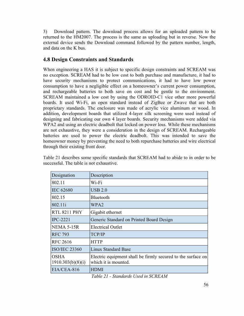
56
3) Download pattern. The download process allows for an uploaded pattern to be returned to the HM2007. The process is the same as uploading but in reverse. Now the external device sends the Download command followed by the pattern number, length, and data on the K bus. 4.8 Design Constraints and Standards
When engineering a HAS it is subject to specific design constraints and SCREAM was no exception. SCREAM had to be low cost to both purchase and manufacture, it had to have security mechanisms to protect communications, it had to have low power consumption to have a negligible effect on a homeowner’s current power consumption, and rechargeable batteries to both save on cost and be gentle to the environment. SCREAM maintained a low cost by using the ODROID-C1 vice other more powerful boards. It used Wi-Fi, an open standard instead of ZigBee or Zwave that are both proprietary standards. The enclosure was made of acrylic vice aluminum or wood. In addition, development boards that utilized 4-layer silk screening were used instead of designing and fabricating our own 4 layer boards. Security mechanisms were added via WPA2 and using an electric deadbolt that locked on power loss. While these mechanisms are not exhaustive, they were a consideration in the design of SCREAM. Rechargeable batteries are used to power the electric deadbolt. This was intended to save the homeowner money by preventing the need to both repurchase batteries and wire electrical through their existing front door. Table 21 describes some specific standards that SCREAM had to abide to in order to be successful. The table is not exhaustive.
Designation Description 802.11 Wi-Fi IEC 62680 USB 2.0 802.15 Bluetooth 802.11i WPA2 RTL 8211 PHY Gigabit ethernet IPC-2221 Generic Standard on Printed Board Design NEMA 5-15R Electrical Outlet RFC 793 TCP/IP RFC 2616 HTTP ISO/IEC 23360 Linux Standard Base OSHA 1910.303(b)(8)(i)
Electric equipment shall be firmly secured to the surface on which it is mounted.
EIA/CEA-816 HDMI Table 21 - Standards Used in SCREAM
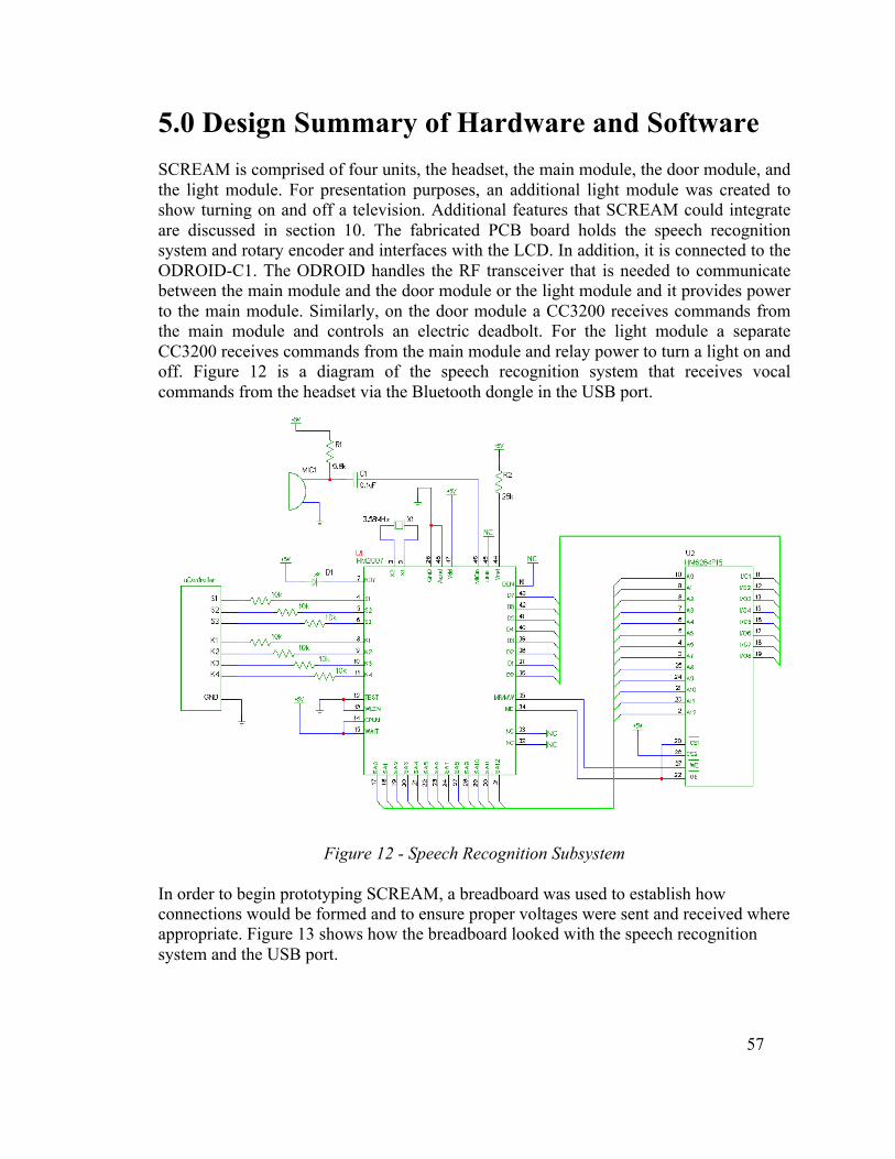
57
5.0 Design Summary of Hardware and Software SCREAM is comprised of four units, the headset, the main module, the door module, and the light module. For presentation purposes, an additional light module was created to show turning on and off a television. Additional features that SCREAM could integrate are discussed in section 10. The fabricated PCB board holds the speech recognition system and rotary encoder and interfaces with the LCD. In addition, it is connected to the ODROID-C1. The ODROID handles the RF transceiver that is needed to communicate between the main module and the door module or the light module and it provides power to the main module. Similarly, on the door module a CC3200 receives commands from the main module and controls an electric deadbolt. For the light module a separate CC3200 receives commands from the main module and relay power to turn a light on and off. Figure 12 is a diagram of the speech recognition system that receives vocal commands from the headset via the Bluetooth dongle in the USB port.
Figure 12 - Speech Recognition Subsystem
In order to begin prototyping SCREAM, a breadboard was used to establish how connections would be formed and to ensure proper voltages were sent and received where appropriate. Figure 13 shows how the breadboard looked with the speech recognition system and the USB port.
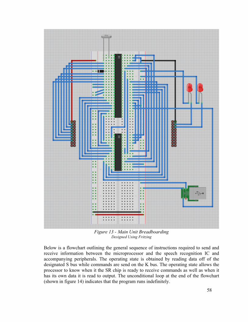
58
Figure 13 - Main Unit Breadboarding
Designed Using Fritzing
Below is a flowchart outlining the general sequence of instructions required to send and receive information between the microprocessor and the speech recognition IC and accompanying peripherals. The operating state is obtained by reading data off of the designated S bus while commands are send on the K bus. The operating state allows the processor to know when it the SR chip is ready to receive commands as well as when it has its own data it is read to output. The unconditional loop at the end of the flowchart (shown in figure 14) indicates that the program runs indefinitely.

59
Figure 14 - Polling Block Diagram
Reprinted from Speech Recognition Tutorial with permission of Imagesco Scientific Instruments
The following three flowcharts outline the specific list of steps to complete a successful recognition, training, and resulting sequence. Due to the difference in clock speeds between the Speech Recognition IC and the TI processor the sequence of steps cannot occur synchronously. To solve this problem, the SR IC uses a status register to reflect its current operating state. So, if the processor reads the register at a high clock rate it can react to the change is state quickly enough to take the appropriate actions. The K bus, which is used for data, similarly has to compensate for the difference in clock rates. Since data is read within a given period following the change in state, the data has to be held on the bus for the specified duration.
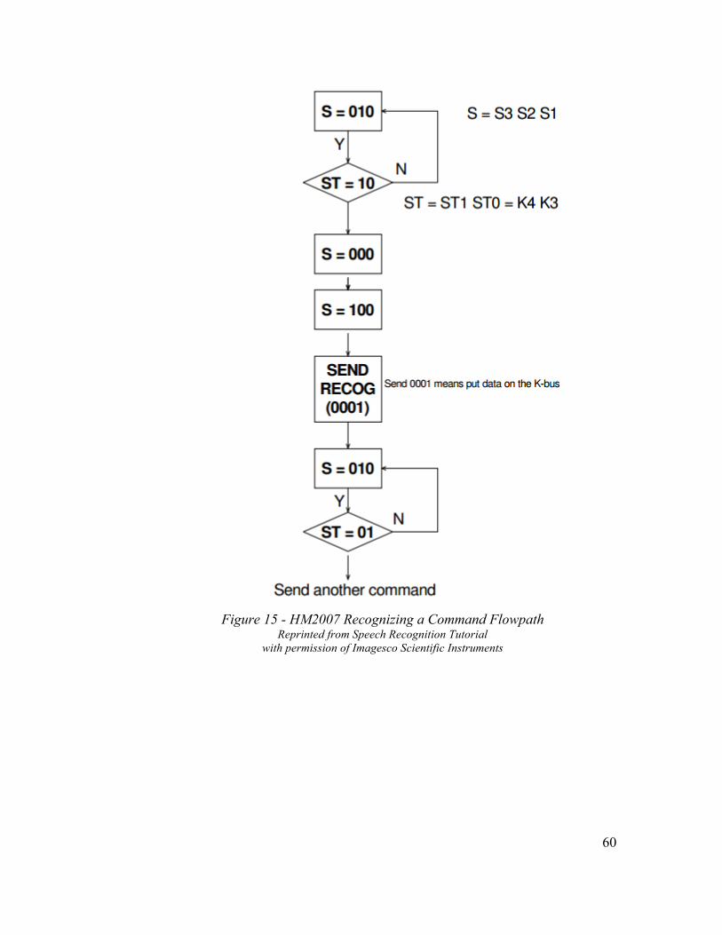
60
Figure 15 - HM2007 Recognizing a Command Flowpath
Reprinted from Speech Recognition Tutorial with permission of Imagesco Scientific Instruments

61
Figure 16 - HM2007 Training a Command Flowpath
Reprinted from Speech Recognition Tutorial with permission of Imagesco Scientific Instruments

62
Figure 17 - HM2007 Result Command Flowpath

63
6.0 Prototype Construction and Coding 6.1 Parts Acquisition
The required parts for SCREAM were acquired based on the requirements and specification values that were needed to construct a prototype for the speech recognition system. Table 18 shows a list of the components needed to to build the prototype for SCREAM. Aside from the electric deadbolt, the components listed in the table were in stock from the selected suppliers, and thus there was no problems acquiring these parts. The deadbolt, however, was not available inside the United States and required international shipping from Hong Kong. In replicating SCREAM it must be noted that shipping from this location was listed as taking 5-15 days and actually took 14 days to arrive.
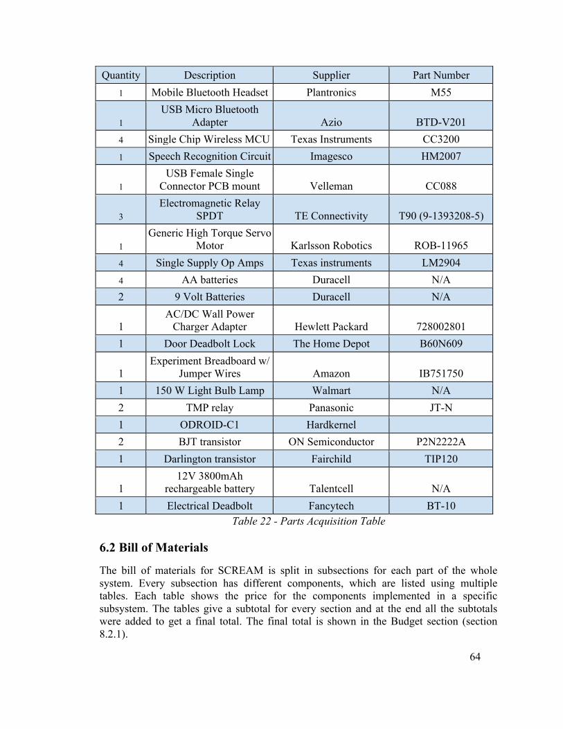
64
Quantity Description Supplier Part Number 1 Mobile Bluetooth Headset Plantronics M55
1 USB Micro Bluetooth
Adapter Azio BTD-V201 4 Single Chip Wireless MCU Texas Instruments CC3200 1 Speech Recognition Circuit Imagesco HM2007
1 USB Female Single
Connector PCB mount Velleman CC088
3 Electromagnetic Relay
SPDT TE Connectivity T90 (9-1393208-5)
1 Generic High Torque Servo
Motor Karlsson Robotics ROB-11965 4 Single Supply Op Amps Texas instruments LM2904 4 AA batteries Duracell N/A 2 9 Volt Batteries Duracell N/A
1 AC/DC Wall Power
Charger Adapter Hewlett Packard 728002801 1 Door Deadbolt Lock The Home Depot B60N609
1 Experiment Breadboard w/
Jumper Wires Amazon IB751750 1 150 W Light Bulb Lamp Walmart N/A 2 TMP relay Panasonic JT-N 1 ODROID-C1 Hardkernel 2 BJT transistor ON Semiconductor P2N2222A 1 Darlington transistor Fairchild TIP120
1 12V 3800mAh
rechargeable battery Talentcell N/A 1 Electrical Deadbolt Fancytech BT-10
Table 22 - Parts Acquisition Table
6.2 Bill of Materials
The bill of materials for SCREAM is split in subsections for each part of the whole system. Every subsection has different components, which are listed using multiple tables. Each table shows the price for the components implemented in a specific subsystem. The tables give a subtotal for every section and at the end all the subtotals were added to get a final total. The final total is shown in the Budget section (section 8.2.1).

65
6.2.1 Headset
Qty Description Supplier Part Number Unit Price Total Price
1 Mobile Bluetooth
Headset Plantronics M55 $38.03 $38.03
1 USB Micro Bluetooth
Adapter Azio BTD-V201 $12.99 $12.99 Total $51.02
Table 23 - BOM for the Headset 6.2.2 Main Unit
Qty Description Supplier Part Number Unit Price Total Price
1 Speech Recognition
Circuit Imagesco HM2007 $179.95 $175.95
1 USB Female Single
Connector PCB mount Velleman CC088
$0.96 $0.96
1 AC/DC Wall Power
Charger Adapter Hewlett Packard 728002801 $5.98 $5.98
1 Experiment Breadboard
w/ Jumper Wires Amazon IB751750 $14.49 $14.49 1 ODROID-C1 Hardkernel N/A $37.95 $37.95 Total $235.33
Table 24 - BOM for the Main Unit 6.2.3 Door Unit
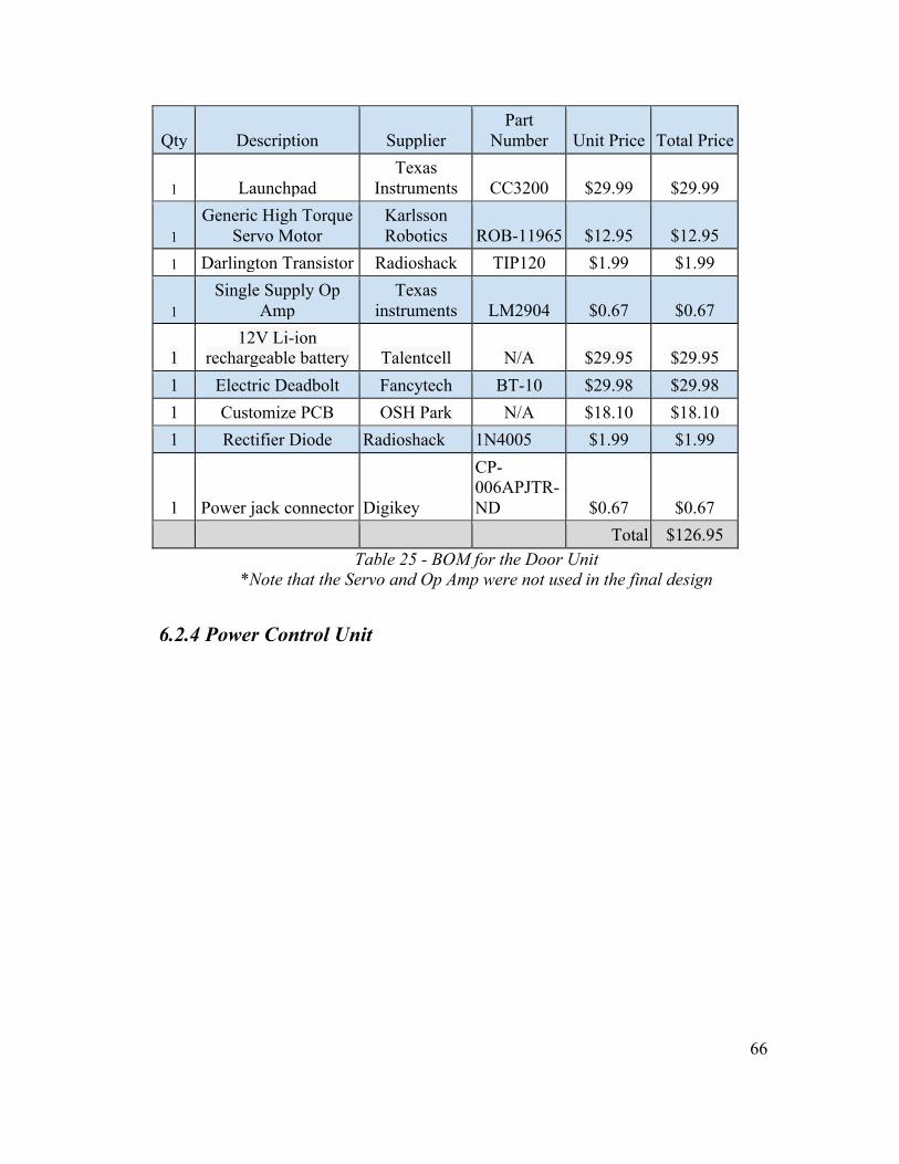
66
Qty Description Supplier Part
Number Unit Price Total Price
1 Launchpad Texas
Instruments CC3200 $29.99 $29.99
1 Generic High Torque
Servo Motor Karlsson Robotics ROB-11965
$12.95 $12.95
1 Darlington Transistor Radioshack TIP120 $1.99 $1.99
1 Single Supply Op
Amp Texas
instruments LM2904 $0.67 $0.67
1 12V Li-ion
rechargeable battery Talentcell N/A $29.95 $29.95 1 Electric Deadbolt Fancytech BT-10 $29.98 $29.98 1 Customize PCB OSH Park N/A $18.10 $18.10 1 Rectifier Diode Radioshack 1N4005 $1.99 $1.99
1 Power jack connector Digikey
CP-006APJTR-ND $0.67 $0.67
Total $126.95 Table 25 - BOM for the Door Unit
*Note that the Servo and Op Amp were not used in the final design
6.2.4 Power Control Unit

67
Qty Description Supplier Part
Number Unit Price Total Price
2 Launchpad Texas
Instruments CC3200 $29.99 $59.98
2 Electromagnetic Relay
SPDT TE Connectivity T90 (9-
1393208-5)
$2.62 $5.24 2 9V batteries Duracell N/A $7.50 $14.99
3 Single Supply Op
Amp Texas
instruments LM2904 $0.67 $2.01 2 BJT transistor Radioshack P2N2222A $1.99 $3.98
1 150 W Light Bulb
Lamp Walmart N/A $6.17 $6.17 2 Power Cord adapter Home depot N/A $5.50 $11.00 2 TMP relay Panasonic JT-N $4.34 $8.68 2 Rectifier Diode Radioshack 1N4005 $1.99 $3.98 2 Customize PCB OSH Park N/A $39.95 $39.95 Total 155.98
Table 26 - BOM for the Power Control Unit *Note that the Op Amp and electromagnetic relay were not used in the final design
6.3 PCB Vendor and Assembly
6.3.1 Design Following the successful software and hardware tests of the SCREAM modules using the development board, the design transitioned to a printed circuit board. The components necessary for the speech recognition circuit, the microcontroller, and all peripherals are embedded on a single circuit board. A board layout capable of housing SCREAM was created using KiCAD and Eagle design suites. FreeAutoRouter was used to make all traces. Design files were uploaded to the manufacturer.
6.3.2 Fabrication OshPark fabricated each of SCREAM’s three different PCBs. They manufacture three copies of each board for $5 per square inch for two layer designs. They have reliable quality and low lead times that are desirable for SCREAM. Figure 18 below shows the board layout for the PCB used in the main module. Figures 19 and 20 show the layouts of the light module and door module respectively. An additional option that was explored was the creation of a Printed Circuit Board
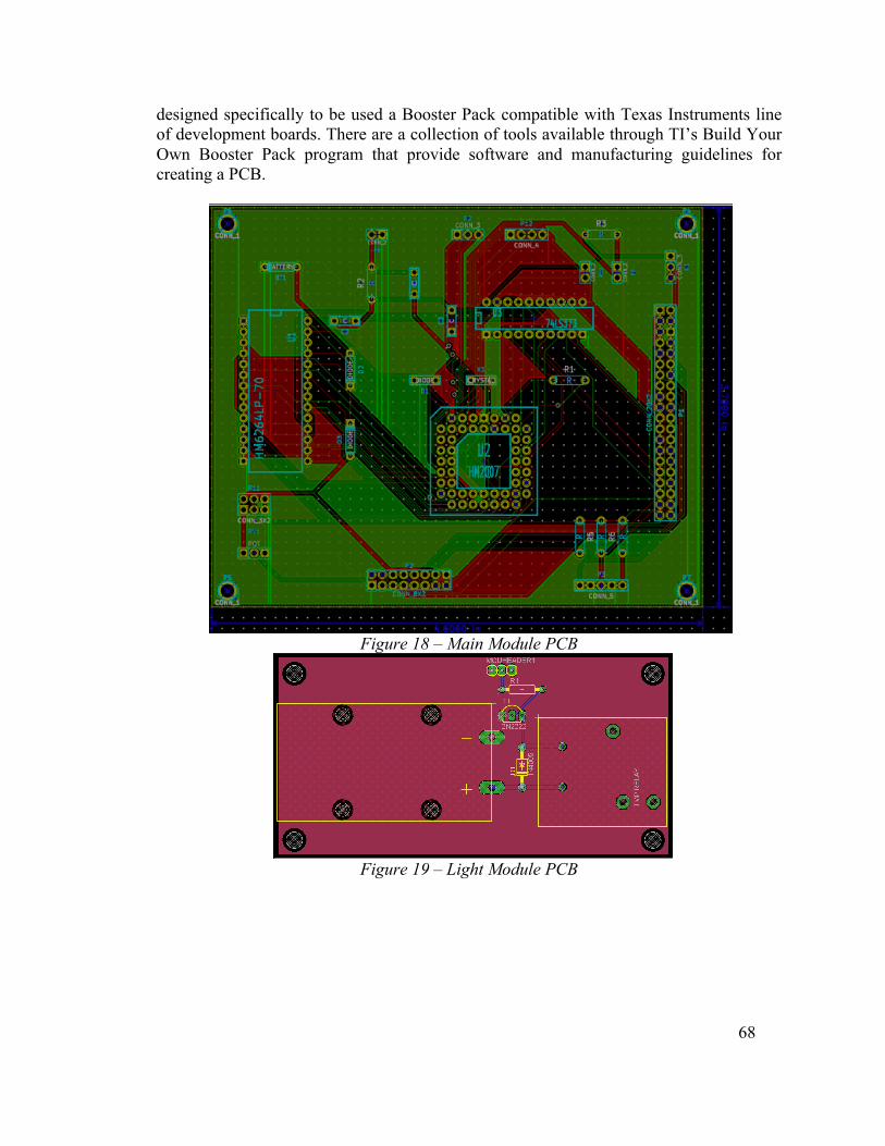
68
designed specifically to be used a Booster Pack compatible with Texas Instruments line of development boards. There are a collection of tools available through TI’s Build Your Own Booster Pack program that provide software and manufacturing guidelines for creating a PCB.
Figure 18 – Main Module PCB
Figure 19 – Light Module PCB

69
Figure 20 – Door Module PCB
6.4 Final Coding Plan
Setup of the ODROID as a software AP required the download, installation, and configuration of specific services. Upon startup, the ODROID-C1 establishes itself as a wireless AP using hostapd, dnsmasq, and iptables on the Arch Linux platform. Hostapd configures the wireless access point, iptables performs traffic routing, and dnsmasq deals with DNS routing and provides DHCP leases. The IP address for the ODROID-C1 uses the reserved address space of 192.168.1.0/24, allowing for up to 100 devices to connect to the AP. Bourne Again Shell (BASH) scripting has been used to automate the setup of these services on startup. Figure XX diagrams the steps to establish the ODROID as a software AP.
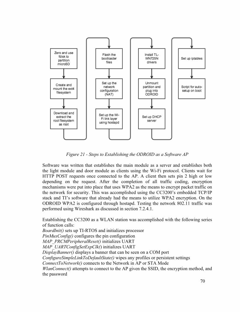
70
Figure 21 - Steps to Establishing the ODROID as a Software AP Software was written that establishes the main module as a server and establishes both the light module and door module as clients using the Wi-Fi protocol. Clients wait for HTTP POST requests once connected to the AP. A client then sets pin 2 high or low depending on the request. After the completion of all traffic coding, encryption mechanisms were put into place that uses WPA2 as the means to encrypt packet traffic on the network for security. This was accomplished using the CC3200’s embedded TCP/IP stack and TI’s software that already had the means to utilize WPA2 encryption. On the ODROID WPA2 is configured through hostapd. Testing the network 802.11 traffic was performed using Wireshark as discussed in section 7.2.4.1. Establishing the CC3200 as a WLAN station was accomplished with the following series of function calls: BoardInit() sets up TI-RTOS and initializes processor PinMuxConfig() configures the pin configuration MAP_PRCMPeripheralReset() initializes UART MAP_UARTConfigSetExpClk() initializes UART DisplayBanner() displays a banner that can be seen on a COM port ConfigureSimpleLinkToDefaultState() wipes any profiles or persistent settings ConnectToNetwork() connects to the Network in AP or STA Mode WlanConnect() attempts to connect to the AP given the SSID, the encryption method, and the password
71
CheckLanConnection() pings the AP gateway sl_Socket() establishes a socket connection SimpleLinkHttpServerCallback() establishes the method through which POST requests change the LED status Wireless socket communication occurs between the ODROID-C1 and the CC3200 when the SRC sends a signal to the outlying modules. Bash scripting is used to identify which module to send the signal to based on a unique MAC address. A C program is used to run both the speech recognition circuit and send commands to outlying modules. Specifically, a curl command sends a POST request to the HTTP server: curl --data "SL_P_ULD=LED1_ON" http://$1/led_demo.html The server accepts the request and manipulates the status of pin 2 that is connected to the green LED. The code used to control the LCD is based on the HD44780 display drivers. Commands are sent from GPIO pins on the ODROID to four parallel data pins on the display. Additional pins are used to control register select, read/write, and enable on the display. When writing consecutive commands to the display with no stalls, information became misinterpreted. To solve the issue, a busy flag provided by the display was polled between each write to ensure no timing issues occurred. All coding was tested for unit functionality of each component needed in the final design before the final code was created. There were a series of tests outlined in section 7.4 Software Testing that were performed. The code for each of these tasks was written in Code Composer Studio and C and tested using the development boards. Following the successful completion of each unit test, additional software was used to facilitate real time code testing and debugging. Print to terminal statements were used to debug code on the CC3200 as viewed with the TeraTerm terminal program. Terminal was used to log in and troubleshoot the ODROID once established as an AP.
7.0 Prototype Testing 7.1 Hardware Test Environment
Hardware testing was performed in the Senior Design Laboratory. At a minimum for the hardware testing a multimeter and oscilloscope had to be available to ensure that components were receiving the required voltage and current and that logic devices were receiving the correct signals at the appropriate intervals. 7.2 Unit Testing
7.2.1 Door Control Unit
The door control unit consisted of an electrical deadbolt to perform the lock/unlock function, a CC3200 to allow communication between this unit and the main module, a

72
12V rechargeable battery to supply power to the deadbolt, and a Darlington transistor to control the current flow from the battery to the electrical deadbolt. Before prototyping, all these parts were tested to check to successful operation. The electric deadbolt was tested by placing the magnetic piece close to the main base of the deadbolt and connecting the two contacts of its solenoid to the 12V rechargeable battery. Once this step is done, the electric actuates its bolt. After the electric deadbolt functionality was checked, the rest of the circuit was assembled using a breadboard. The CC3200 was connected to the 270 Ω resistor, which controls the amount of current that flows to the transistor. Using the digital multimeter, the current was measured before the transistor was connected with the resistor. Then the transistor was tested in saturation mode. The CC3200 sent a high signal to the circuit in order to set the transistor in saturation. A good way to check if the transistor is in saturation is by using the multimeter to measure the base-emitter junction voltage and collector-emitter voltage, and compare those values with ones shown on the datasheet for the TIP120 Darlington transistor. When all the elements of the door control unit were operating the way they were supposed to, then a simulation was run using Energia that controls the output of a specific GPIO pin from the CC3200. Running this simulation helped to check if the system can control the actuation of the electric deadbolt. 7.2.2 Speech Recognition Unit
The speech recognition unit had to be tested in a quiet environment where it can assimilate the voice of the user. The speech recognition circuit is continually listening when it is turned on. An easy way to test the speech recognition unit is to repeat a trained word into the wireless headset and check if the number of the word displayed on the digital display is the right output for that specific word. For instance, if the word “test” was trained as word number 25, then the number 25 should be displayed on the digital display when the user says the word “test” into the wireless headset. In addition, the speech recognition unit gave error codes that were displayed on the screen to let the user know if there was a failure in the input word. The speech recognition unit displayed the following error codes if there was an error in the voice input: 55 = word too long 66 = word too short 77 = word no match
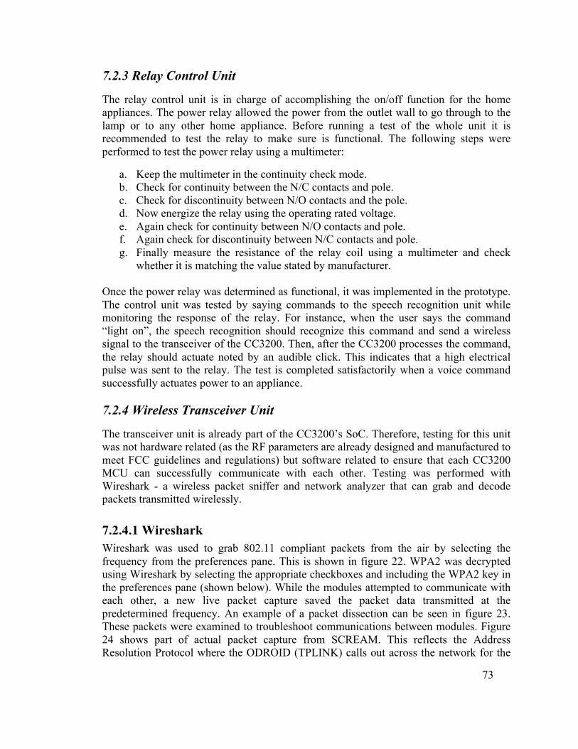
73
7.2.3 Relay Control Unit
The relay control unit is in charge of accomplishing the on/off function for the home appliances. The power relay allowed the power from the outlet wall to go through to the lamp or to any other home appliance. Before running a test of the whole unit it is recommended to test the relay to make sure is functional. The following steps were performed to test the power relay using a multimeter:
a. Keep the multimeter in the continuity check mode. b. Check for continuity between the N/C contacts and pole. c. Check for discontinuity between N/O contacts and the pole. d. Now energize the relay using the operating rated voltage. e. Again check for continuity between N/O contacts and pole. f. Again check for discontinuity between N/C contacts and pole. g. Finally measure the resistance of the relay coil using a multimeter and check
whether it is matching the value stated by manufacturer. Once the power relay was determined as functional, it was implemented in the prototype. The control unit was tested by saying commands to the speech recognition unit while monitoring the response of the relay. For instance, when the user says the command “light on”, the speech recognition should recognize this command and send a wireless signal to the transceiver of the CC3200. Then, after the CC3200 processes the command, the relay should actuate noted by an audible click. This indicates that a high electrical pulse was sent to the relay. The test is completed satisfactorily when a voice command successfully actuates power to an appliance. 7.2.4 Wireless Transceiver Unit
The transceiver unit is already part of the CC3200’s SoC. Therefore, testing for this unit was not hardware related (as the RF parameters are already designed and manufactured to meet FCC guidelines and regulations) but software related to ensure that each CC3200 MCU can successfully communicate with each other. Testing was performed with Wireshark - a wireless packet sniffer and network analyzer that can grab and decode packets transmitted wirelessly.
7.2.4.1 Wireshark Wireshark was used to grab 802.11 compliant packets from the air by selecting the frequency from the preferences pane. This is shown in figure 22. WPA2 was decrypted using Wireshark by selecting the appropriate checkboxes and including the WPA2 key in the preferences pane (shown below). While the modules attempted to communicate with each other, a new live packet capture saved the packet data transmitted at the predetermined frequency. An example of a packet dissection can be seen in figure 23. These packets were examined to troubleshoot communications between modules. Figure 24 shows part of actual packet capture from SCREAM. This reflects the Address Resolution Protocol where the ODROID (TPLINK) calls out across the network for the
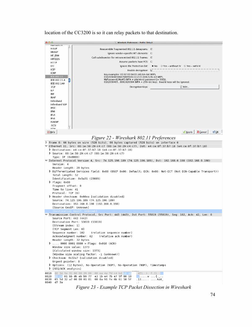
74
location of the CC3200 is so it can relay packets to that destination.
Figure 22 - Wireshark 802.11 Preferences
Figure 23 - Example TCP Packet Dissection in Wireshark
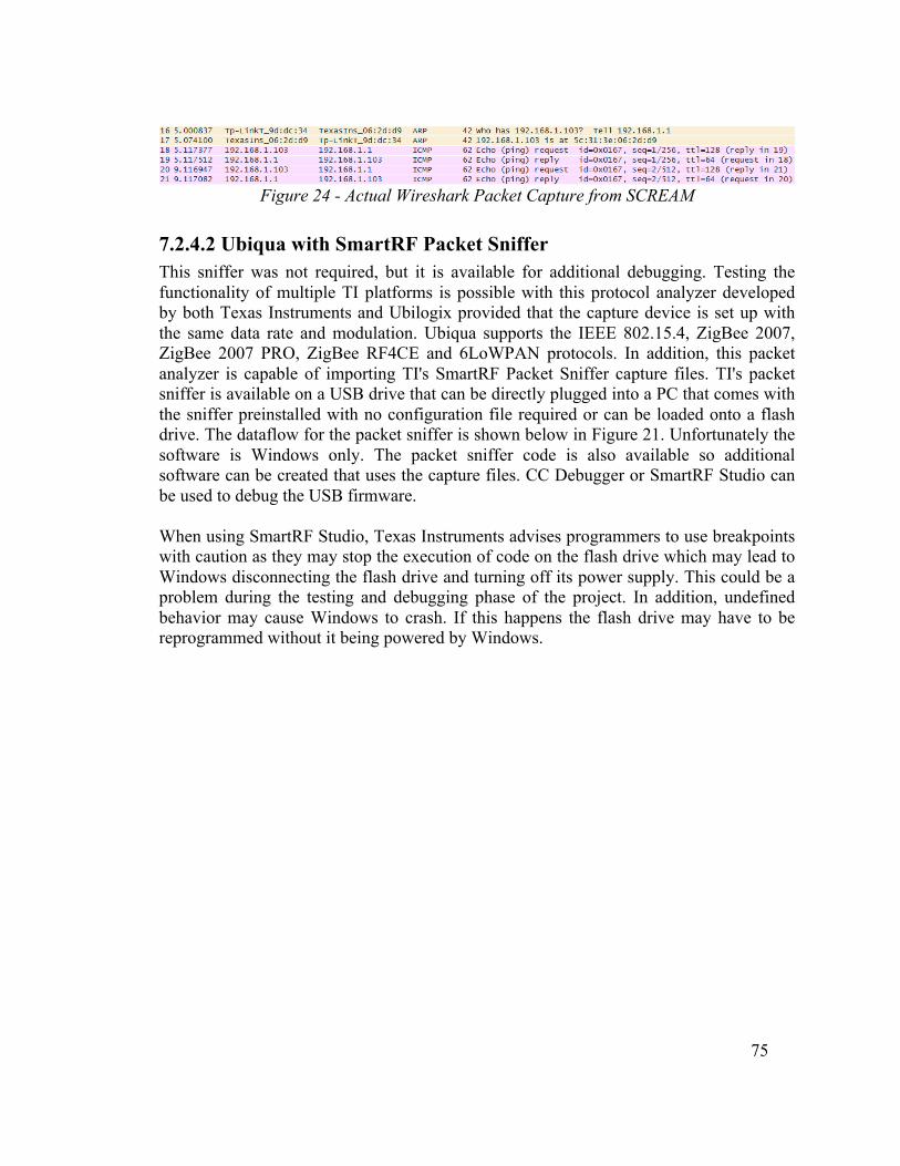
75
Figure 24 - Actual Wireshark Packet Capture from SCREAM
7.2.4.2 Ubiqua with SmartRF Packet Sniffer This sniffer was not required, but it is available for additional debugging. Testing the functionality of multiple TI platforms is possible with this protocol analyzer developed by both Texas Instruments and Ubilogix provided that the capture device is set up with the same data rate and modulation. Ubiqua supports the IEEE 802.15.4, ZigBee 2007, ZigBee 2007 PRO, ZigBee RF4CE and 6LoWPAN protocols. In addition, this packet analyzer is capable of importing TI's SmartRF Packet Sniffer capture files. TI's packet sniffer is available on a USB drive that can be directly plugged into a PC that comes with the sniffer preinstalled with no configuration file required or can be loaded onto a flash drive. The dataflow for the packet sniffer is shown below in Figure 21. Unfortunately the software is Windows only. The packet sniffer code is also available so additional software can be created that uses the capture files. CC Debugger or SmartRF Studio can be used to debug the USB firmware. When using SmartRF Studio, Texas Instruments advises programmers to use breakpoints with caution as they may stop the execution of code on the flash drive which may lead to Windows disconnecting the flash drive and turning off its power supply. This could be a problem during the testing and debugging phase of the project. In addition, undefined behavior may cause Windows to crash. If this happens the flash drive may have to be reprogrammed without it being powered by Windows.
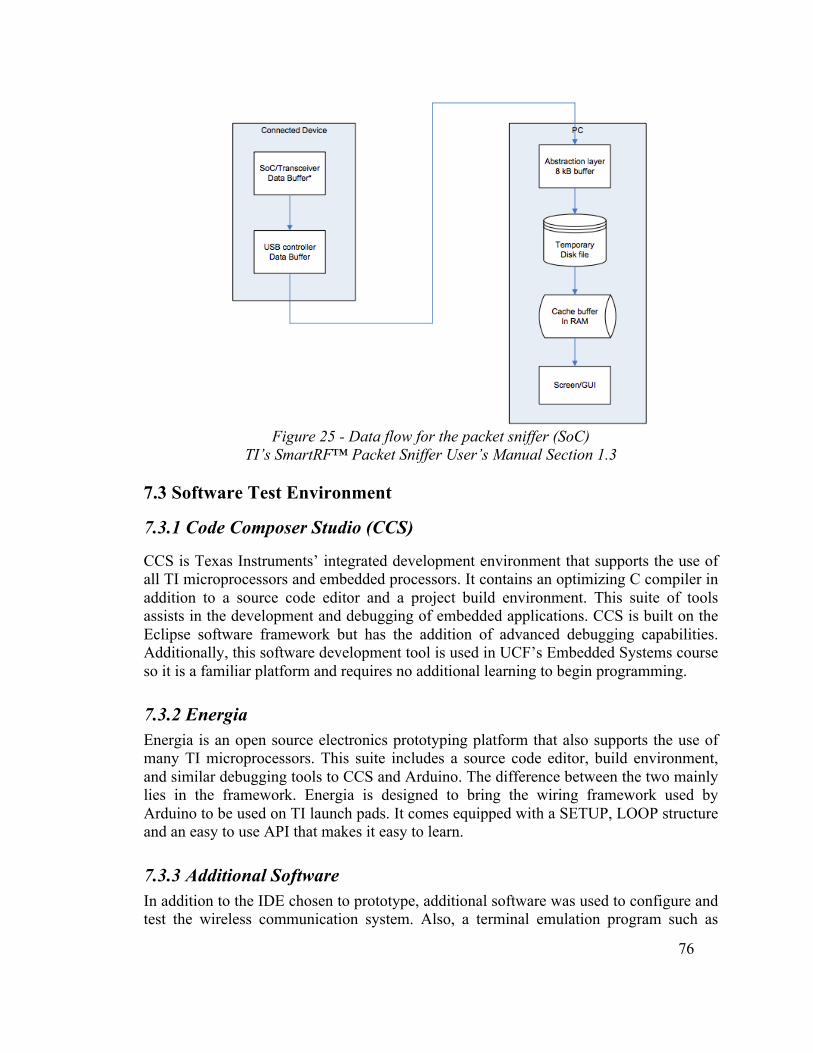
76
Figure 25 - Data flow for the packet sniffer (SoC)
TI’s SmartRF™ Packet Sniffer User’s Manual Section 1.3 7.3 Software Test Environment
7.3.1 Code Composer Studio (CCS)
CCS is Texas Instruments’ integrated development environment that supports the use of all TI microprocessors and embedded processors. It contains an optimizing C compiler in addition to a source code editor and a project build environment. This suite of tools assists in the development and debugging of embedded applications. CCS is built on the Eclipse software framework but has the addition of advanced debugging capabilities. Additionally, this software development tool is used in UCF’s Embedded Systems course so it is a familiar platform and requires no additional learning to begin programming.
7.3.2 Energia
Energia is an open source electronics prototyping platform that also supports the use of many TI microprocessors. This suite includes a source code editor, build environment, and similar debugging tools to CCS and Arduino. The difference between the two mainly lies in the framework. Energia is designed to bring the wiring framework used by Arduino to be used on TI launch pads. It comes equipped with a SETUP, LOOP structure and an easy to use API that makes it easy to learn.
7.3.3 Additional Software
In addition to the IDE chosen to prototype, additional software was used to configure and test the wireless communication system. Also, a terminal emulation program such as
77
TeraTerm (recommended by TI), Hyperterminal, or Putty was used to test data transfers over the network. Wireshark was used to sniff wireless packet traffic and helped troubleshoot problems that arose with using Wi-Fi and establishing the ODROID as an access point. An operational version of Uniflash is absolutely essential is troubleshooting the CC3200 as it will not maintain programming on its SFLASH without this utility. Uniflash is TI’s proprietary flasher available at no cost and subject to export controls. Certain pins must be jumped on the board in order to flash the board (refer to the wiki for more information). After flashing, power must be removed from the board, the jumper removed, and power cycle the board to check if the programming of the SFLASH was completely successfully. This must be done in this order as TI has experienced a static buildup on the board resulting in unpredictable and often fatal board behavior. Example Uniflash configurations are available through the CC3200 SDK. Flashing the CC3200s for SCREAM could only be accomplished through the use of these example configurations, replacing the main.bin file for the newly compiled .bin file in the CCS workspace. 7.4 Software Testing
There was a series of software tests that were performed throughout all stages of system integration. The first tests used the ODROID to ensure successful operation of the main module and subsequent tests were done using each additional peripheral. The list of test stages is outlined in table 27.
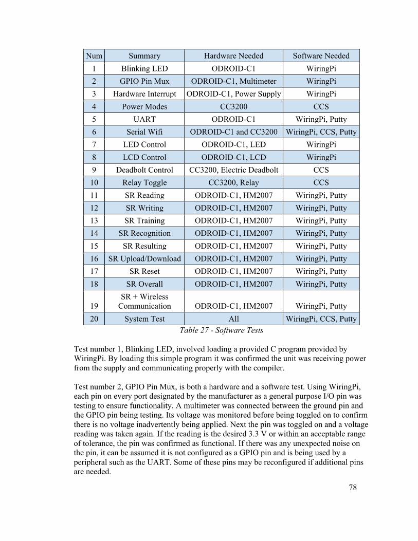
78
Num Summary Hardware Needed Software Needed 1 Blinking LED ODROID-C1 WiringPi 2 GPIO Pin Mux ODROID-C1, Multimeter WiringPi 3 Hardware Interrupt ODROID-C1, Power Supply WiringPi 4 Power Modes CC3200 CCS 5 UART ODROID-C1 WiringPi, Putty 6 Serial Wifi ODROID-C1 and CC3200 WiringPi, CCS, Putty 7 LED Control ODROID-C1, LED WiringPi 8 LCD Control ODROID-C1, LCD WiringPi 9 Deadbolt Control CC3200, Electric Deadbolt CCS 10 Relay Toggle CC3200, Relay CCS 11 SR Reading ODROID-C1, HM2007 WiringPi, Putty 12 SR Writing ODROID-C1, HM2007 WiringPi, Putty 13 SR Training ODROID-C1, HM2007 WiringPi, Putty 14 SR Recognition ODROID-C1, HM2007 WiringPi, Putty 15 SR Resulting ODROID-C1, HM2007 WiringPi, Putty 16 SR Upload/Download ODROID-C1, HM2007 WiringPi, Putty 17 SR Reset ODROID-C1, HM2007 WiringPi, Putty 18 SR Overall ODROID-C1, HM2007 WiringPi, Putty
19 SR + Wireless
Communication ODROID-C1, HM2007 WiringPi, Putty 20 System Test All WiringPi, CCS, Putty
Table 27 - Software Tests
Test number 1, Blinking LED, involved loading a provided C program provided by WiringPi. By loading this simple program it was confirmed the unit was receiving power from the supply and communicating properly with the compiler. Test number 2, GPIO Pin Mux, is both a hardware and a software test. Using WiringPi, each pin on every port designated by the manufacturer as a general purpose I/O pin was testing to ensure functionality. A multimeter was connected between the ground pin and the GPIO pin being testing. Its voltage was monitored before being toggled on to confirm there is no voltage inadvertently being applied. Next the pin was toggled on and a voltage reading was taken again. If the reading is the desired 3.3 V or within an acceptable range of tolerance, the pin was confirmed as functional. If there was any unexpected noise on the pin, it can be assumed it is not configured as a GPIO pin and is being used by a peripheral such as the UART. Some of these pins may be reconfigured if additional pins are needed.

79
Test number 3, Hardware Interrupt, tested the usage of external interrupts. The manufacturer diagrams designate a number of pins as having the capability of interrupts. To test these pins a simple program was written to confirm their use. An interrupt function was triggered that changed the state of the processor and toggled one of the embedded LEDs. To test the interrupt an external power supply set to 3.3V was applied to the pin. If the LED is toggled, the interrupt is functional. Test number 4, Power Modes, tested the use of the four MCU power modes and the three Network Subsystem power modes. Table 28 describes the device power modes:
MCU Power Mode
Network Sub-system
Disabled LPDS Active Hibernate Hibernate N/A N/A LPDS LPDS LPDS Active Sleep Active Active Active Active Active Active Active
Table 28 - Device Power Modes Each of the power modes active subsystems was tested. To ensure minimum power consumption during operation, the lowest possible power mode that provides the necessary functionality was used. Test number 5, UART, tested the use of the using real time keyboard input. Although the end user does not have access to the UART, it enabled additional real time software tests to be performed. There is a sample UART program available in WiringPi that was modified based on the project’s requirements. Test number 6, Serial Wi-Fi, was the first test performed that uses the wireless communication ability of the ODROID-C1. A program was written that tests the socket connection between the ODROID and the CC3200. The server program sent a test UDP packet to the client program. Once this test was complete the central module had the ability to communicate with a remote module. Test number 7, LED Control, tested the use of external LEDs. Individual LEDS were connected to GPIO pins and toggled on and off. This test ensured that proper power could be supplied to the LEDs so that they could reach the proper light level. Test number 8, LCD Control, tested the use of the two 7 segment LCD displays and their controllers. A program was written that tests the processor’s ability to write data to the LCD display using the controllers.

80
Test number 9, Deadbolt Control, tested the microcontroller’s ability to drive the electric deadbolt. The door module unit was breadboarded and the electric deadbolt was connected to the CC3200. This test determined that the CC3200 was capable of driving the electric deadbolt on a GPIO. Test number 10, Relay Toggle, connected the relay circuit to the GPIO pins on the development board. The pins were toggled on and off and the relay was monitored to ensure it is reacting appropriately. Test number 11, SR Reading, attached the HM2007’s S bus to the GPIO pins. Their status was polled by the CC3200’s software to detect the SR circuit’s operating state. Each of the four operating states was entered to ensure the processor could detect them all. Test number 12, SR Writing, attached the HM2007’s K bus to the GPIO pins. This test ensured the HM2007 is able to receive input from the processor. Both of the Reading and Writing functions described above were used to test the other Speech Recognition functions. Test number 13, SR Training, tested the processor’s ability to communicate to the HM2007 that it wants to train a command. It provided the SR circuit with the line number to be trained. Test number 14, SR Recognition, tested the processor’s ability to communicate to the HM2007 that it wants to listen for a user command. At this point the SR circuit entered recognition mode for 1.92 seconds while it listens to input from the microphone. After the recognition period ends, the circuit entered resulting mode to process it. Test number 15, SR Resulting, returned information to the processor on the K bus. It returned the line number of the word if it is recognized or an error code if it was either not recognized or invalid. Test number 16, SR Upload/Download, tested the ability to upload and download stored recordings from the HM2007’s memory to the processor’s memory. The sequence of commands sent between the two units includes the command code, line number, and data. This process is further explained in Section 4.7 Hardware Design Details - Speech Recognition. Test number 17, SR Reset, gave the user the ability to reset the SR circuit. When the reset command is received, the HM2007 erased all stored data in memory and power cycle. Test number 18, SR Overall, tested the performance of all of the speech recognition features. The programmer was able to issue text command to the processor using the UART interface. All of the functions were thoroughly tested to confirm compatibility.

81
Test number 19, SR + Wireless Communication, extended the speech recognition program to allow for wireless communication capabilities. The ODROID-C1 acted as the central processor and a CC3200 acted as a remote processor. After an ON or OFF command is received, the central processor sent a wireless signal to the remote processor which used an embedded LED to indicate its state. Test number 20, System Test, extended the speech recognition and wireless communication program to incorporate the relays and door unit. It had the same functionally as test 19 but controlled the other subsystems instead of the embedded LEDs. Following the analysis of the results from Test number 11, it was determined that the HM2007 being used in our SR circuit had a design flaw. As a result, the decision was made to replace the planned software writing ability of the processor was a hardware keyboard.
7.5 Integrated System Testing
Integrated testing occurred in order to test the system prior to presenting it. The main module is the most important facet of SCREAM as it relays commands to and from the individual modules. Therefore, integrated testing occurred with the access point and an outlying module one at a time to ensure that each facet of SCREAM works as intended prior to testing the entire system as a whole. 7.5.1 Main Module and Headset
The first integrated test occurred between the main module and the wireless headset. An external power source was required for the main module, and the headset should be fully charged for this test. The test began from a shutdown state and power was applied to the main module and a headset was attached to the audio port. At this point a user attempted to vocally train the main unit. Each of the remote modules are assigned two training channels, one for the module on command and the second to turn it off. The two channels are consecutive lines and are according to the module number. For example channels 1 and 2 were used to turn on and off module 1, similarly channels 3 and 4 controlled module 2. Training the module is performed by using the rotary encoder until the desired channel number is displayed on the LCD display. Next, press the button labeled TRAIN, which allows the system to record the next 1.92 seconds of audio. After the recording is stored the system blinks an LED to the user to indicate it was successful. Commands are given to the module to test if the module successfully receives and processes commands. Mock commands for SCREAM can be given; such as to turn off the lights, with no expectation of the commands to be successful as this is only part of the full SCREAM system. The test was successful at 10 feet, so the user moved to 20 feet, still line of sight, and the test was run again. Following the completion of the test at 20

82
feet, the test was run a third time at 30 feet. At 30 feet there was noticeable attenuation between the time the command was issued and when a module responded. The test was considered successful when the following conditions were met: the main unit was successfully trained, commands can be relayed up to 30 feet away, the main unit processed commands and relayed them with the appropriate module. 7.5.2 Main Module and Door Module
Only once the integrated testing between the main module and the headset is complete could the test between the main module and the door module begin. An external power source was required for the main module and the batteries for the door module should be fully charged. The test was run again from a cold system. The main module was trained. The headset was still used to relay commands from a set distance of 5 feet away from the main module. Each of the remote modules was assigned two training channels, one was for the module on command and the second was to turn it off. The two channels were consecutive lines and were ordered according to the module number. For example channels 1 and 2 were used to turn on and off module 1, similarly channels 3 and 4 controlled module 2. The user trained the module by using the rotary encoder until the desired channel number was displayed on the LCD display. Next, press the button labeled TRAIN, which allows the system to record the next 1.92 seconds of audio. After the recording is stored the system blinks an LED to the user to indicate it was successful. The commands ‘LOCK DOOR’ and ‘UNLOCK DOOR’ are spoken into the headset and received by the main module. The main module then processed and relays these commands to the door module. The door module receives and processes these commands and provides power to the deadbolt which then locks or unlocks the door as appropriate. The test was considered successful because the following conditions were met: the main unit was successfully trained, the main unit processed commands and relayed them with the appropriate module, the door module received and processed commands and appropriately manipulated the deadbolt, the deadbolt successfully locked and unlocked the door on command. 7.5.3 Main Module and Light Module
Only once sections 7.5.1 and 7.5.2 are complete can the test between the main module and the light module begin. An external power source was required for the main module and the batteries for the door module should be fully charged. The test was run again from a cold system. The main module was trained. The headset was still used to relay commands from a set distance of 5 feet away from the main module. Each of the remote modules was assigned two training channels, one was for the module on command and the second was to turn it off. The two channels were consecutive lines and were ordered according to the module number. For example channels 1 and 2 were
83
used to turn on and off module 1, similarly channels 3 and 4 controlled module 2. The user trained the module by using the rotary encoder until the desired channel number was displayed on the LCD display. Next, press the button labeled TRAIN, which allows the system to record the next 1.92 seconds of audio. After the recording is stored the system blinks an LED to the user to indicate it was successful. The commands ‘LIGHT ON’ and ‘LIGHT OFF’ were spoken into the headset and received by the main module. The main module then processed and relayed these commands to the light module. The light module received and processed these commands and provided power to the light as appropriate. The test was considered successful because the following conditions were met: the main unit was successfully trained, the main unit processed commands and relayed them with the appropriate module, the light module received and processed commands and appropriately provided power to the light. 7.5.4 Overall System Test
All test sections indicated before this point must be complete prior to the beginning of the overall integrated system test. An external power source was required for the main module and the batteries for the door module should be fully charged. The test was run again from a cold system. The main module was trained. The headset was still used to relay commands from a set distance of 10 feet away from the main module. Each of the remote modules was assigned two training channels, one was for the module on command and the second was to turn it off. The two channels were consecutive lines and were ordered according to the module number. For example channels 1 and 2 were used to turn on and off module 1, similarly channels 3 and 4 controlled module 2. The user trained the module by using the rotary encoder until the desired channel number was displayed on the LCD display. Next, press the button labeled TRAIN, which allows the system to record the next 1.92 seconds of audio. After the recording is stored the system blinks an LED to the user to indicate it was successful. Commands were given to the module to test if the module successfully received and processed commands. The aforementioned commands were used, in no particular order, to ensure that the main module received commands, processed them, and relayed them to the appropriate module correctly. If the test is successful at 10 feet, the user then moved to 20 feet, still line of sight, and the test was run again. Following the completion of the test at 20 feet, the test was run a third time at 30 feet. The test was considered successful because the following conditions were met: the main unit was successfully trained, commands could be relayed up to 30 feet away, the main unit processed commands and relayed them to the appropriate module, the corresponding module received the commands, processed them, and the appropriate action was taken by that module.

84
7.6 Presentation Environment
The presentation environment was expected to be the final environment used to show SCREAM’s functionality in its entirety. A table supported all modules like portrayed in figure 23. Prior to presenting, the system was already vocally trained and a list of words that have been trained were recorded. The modules were placed on the farthest possible ends of the table and were setup in those locations. Setup included pairing the subordinate modules to the access point in a stationary position and ensuring line of sight was available between the modules and the access point. The light module and access point needed an external power source. The door module needed fresh batteries. Presentation involved a user speaking a command into the headset. The access point received the command, processed the command, and relayed it to the appropriate module. That module then performed the action assigned. At least four commands must be issued, locking and unlocking the door and turning the light on and off. The test was a success because the door module successfully locked and unlocked the door and the light module successfully turned the light on and off.
Figure 26 - Presentation Environment Layout
8.0 Administrative Content 8.1 Project Milestones
A list of major milestones was compiled to keep the project from suffering from schedule creep. The milestones should be used as guidelines to completing both the research paper

85
and the prototype on time. It is extremely important to finish as much of the research as possible by the middle of October in order to begin designing the prototype. Much of the paper can be completed in tandem to reduce the workload towards the end of the first semester. The design stage of the project must be finished by the end of October to allow time to finish the final proposal paper and begin parts acquisition. Prototyping is intended to be completed by the first week in February and must be finished to allow time for testing, scheduled to be finished before the second week in March. Please see Appendix D for a detailed timeline. 8.2 Project Budget and Finance Discussions
8.2.1 Budget
SCREAM is intended to service a niche in the HAS market where customers may be intimidated by the cost needed to implement or maintain a HAS. Therefore, the budget for SCREAM is modest and intended to reduce cost wherever possible. Table 17 below delineates the budget for each component with a contingency built in to safeguard against unforeseen costs. Five hundred is the target budget amount in order to keep SCREAM affordable but in the initial budget outline The Boeing Company funded $528. Many HASs already available on the market cost more than SCREAM, either via subscription where the cost is broken up over time or upfront in sheer cost of components and installation. Additional units of SCREAM would be cheaper due to the increased costs associated with prototyping. The first table, the original budget, shows the original cost breakdown that was assumed to be needed to acquisition the parts needed for SCREAM. Notice that most values are rounded up to the nearest whole dollar and tax and shipping are not included. Rounding up to the nearest whole dollar and adding the contingency field were ways to ensure that getting parts for SCREAM would not go over budget. The second table, the complete projected budget, is a more complete price estimation of what exact parts were needed and the prices are not rounded.
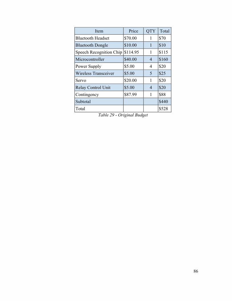
86
Item Price QTY Total Bluetooth Headset $70.00 1 $70 Bluetooth Dongle $10.00 1 $10 Speech Recognition Chip $114.95 1 $115 Microcontroller $40.00 4 $160 Power Supply $5.00 4 $20 Wireless Transceiver $5.00 5 $25 Servo $20.00 1 $20 Relay Control Unit $5.00 4 $20 Contingency $87.99 1 $88 Subtotal $440 Total $528
Table 29 - Original Budget

87
Qty Description Supplier Part Number Unit Price
Total Price
1 Mobile Bluetooth Headset Plantronics M55 $38.03 $38.03 1 USB Micro Bluetooth Adapter Azio BTD-V201 $12.99 $12.99 1 Speech Recognition Circuit Imagesco HM2007 $179.95 $179.95
1 USB Female Single Connector
PCB mount Velleman CC088 $0.96 $0.96
1 AC/DC Wall Power Charger
Adapter Hewlett Packard 728002801 $5.98 $5.98
1 Experiment Breadboard w/
Jumper Wires Amazon IB751750 $14.49 $14.49
1 Single Chip Wireless MCU Texas
Instruments CC3200 $18.08 $18.08
1 Generic High Torque Servo
Motor Karlsson Robotics ROB-11965 $12.95 $12.95
1 Lithium 3.6 V battery Saft LS14250 $4.00 $4.00
1 Single Supply Op Amp Texas
Instruments LM2904 $0.67 $0.67 1 6 Volt Battery Duracell 28A $4.79 $4.79
1 Door Deadbolt Lock The Home
Depot B60N609 $29.98 $29.98
3 Single Chip Wireless MCU Texas
Instruments CC3200 $18.08 $54.04
3 Electromagnetic Relay SPDT TE
Connectivity T90 9-
1393208-5 $2.62 $7.86 3 Lithium 3.6 V battery Saft LS14250 $4.00 $12.00
3 Single Supply Op Amp Texas
Instruments LM2904 $0.67 $2.01 3 6 Volt Battery Duracell 28A $4.79 $14.37 1 150 W Light Bulb Lamp Walmart N/A $6.17 $6.17 Total $419.32
Table 30 - Complete Projected Budget 8.2.2 Financial Discussions
After the project was completed to entirety, the total cost of production could be evaluated. Excluding tax, shipping and handling, the final budget for each module is as follows: main module - $192.36, door module - $110.02, electronic module - $64.12. If the product were to be mass-produced, buying in bulk and using a smaller board design

88
could optimize manufacturing cost.
9.0 Project Summary and Conclusions SCREAM is a HAS intended to fill an unfulfilled market space in current market offerings. By providing a way to wirelessly and vocally control enabled devices, SCREAM is empowering its users to be both energy conscious and more independent despite physical or mental limitations. SCREAM is a robust HAS that can enable many to use a HAS when they might have previously been intimidated by the cost or the technical knowledge required to install and use one. SCREAM uses an embedded architecture and SoC technologies allow the system to be cheaper, smaller, and easier to use. It is cheaper because the system is cheaper to manufacture. That is, the system requires a commonly used headset with few limitations in order to send commands. It does not use a proprietary protocol to package data so there are plenty of IC manufacturers that make the parts required for SCREAM to function and no scarcity of parts. A premade RF module is used which reduces the cost and time of development. Many of the parts for the servos and relays come from eastern manufacturers where the labor cost is lower and so the cost of SCREAM is lower. There is no recurring subscription to renew each year or pay each month. SCREAM is smaller because many of the systems SCREAM needs to run are coupled together resulting in the system using less space. For example, the transmitter and receiver are coupled together in a transceiver and the transceiver is only half duplex and not full duplex (which is more expensive) because the system does not need it. The transceiver and the processor that handles protocol manipulation are present on the same chip. SCREAM uses an embedded platform requiring no PC or server to use. The system is easier to use because it is used vocally with little system manipulation required to voice train the speech recognition chip. There is no GUI to be confused by, no overarching operating system to configure or troubleshoot or update, no additional wiring, and maintenance the system requires is minimal. Maintenance is confined to changing the vocal commands as required and charging batteries. There are few moving parts with the exception of the servos to operate the door lock. SCREAM uses a Bluetooth headset to allow a user to vocally control devices with minimal physical interaction. The headset is easy to procure because of the popularity of smart phone devices and the necessity of hands free driving techniques. The headset is easy to pair with the Bluetooth dongle. The dongle is also easy to procure due to the rise in popularity of enabling PCs to use Bluetooth devices with programs like Skype. The headset is Bluetooth 2.1 or later compliant which allows some increased security when using the system and acts as a preventative measure for unwanted intruders. The user speaks into the headset that is relayed to a fabricated board that houses a speech recognition system. The speech recognition system is easy to train, and stores trained vocal commands. Once it receives a command the system processes the audio to try to

89
compare it with the files it stored during training. Once it identifies a command with one already stored it communicates with the ODROID-C1. The ODROID-C1 communicates via Wi-Fi to a corresponding module, either to manipulate the door or to manipulate a lamp. WPA2 was used to encrypt the data traffic flowing between modules and also acted as a preventative measure for unwanted intruders. The door module and the light module received commands from the main module and either a relay or a deadbolt acted accordingly. Although there are many ways that SCREAM could be improved upon, SCREAM acted as a HAS that is easy to install, cheap to manufacture, and easy to use and maintain.
10.0 Extending the Design 10.1 User Interface and App Development
Currently the user interface is limited to only accepting voice commands. Most modern home automation systems rely on the use of a touch screen display, typically in the form of a tablet or smartphone. A feature that could be added to SCREAM would be the added tactile use through a cellphone. Android, a popular open source mobile operating system is a common platform for app development due to its Android Open Source Project (AOSP) source code being available for modification. 10.2 Multiple Users
Currently SCREAM is limited to control via a single wireless microphone. While sufficient for some situations, others living in multiple person households may desire additional microphones so each person in the house could operate the system. The addition of having multiple analog inputs would require additional hardware responsible for multiplexing the signals through a single medium. 10.3 Vocal Confirmation
SCREAM only reports feedback to the user in the form of the LCD display and LED lights. By converting the wireless audio receiver into a transceiver, it could extend the design capabilities to allow for tones to be played back to the user to confirm their commands were recognized and completed or if there was an error and they need to repeat the command. Additionally the use of Text-to-Speech hardware could be implemented to allow for more accurate feedback. 10.4 Email, Text Alerts, and Remote Manipulation
SCREAM has the ability to monitor which appliances are turned on and also if doors are left unlocked. A current trend in home automation is the use of text and email alerts to remind the homeowner when the door is left unlocked to help prevent unauthorized entry and also when appliances are left on when no one is home. Since the product is already connected using Wi-Fi the ability to send an email to the user would be within its
90
capabilities. Some HASs allow the user to manipulate modules in the home remotely but this is not currently supported in SCREAM. For example, while the homeowner is away from the domicile they can watch live camera feeds of their home and turn lights on and off from a phone application. This could be implemented through the use of a home server or other computer that could provide the additional computational power required to implement this feature. 10.5 Microphone Repeaters
As designed, SCREAM uses a microphone that uses a Bluetooth enabled headset that pairs with a unit on the main device. This limits the overall range of the system to the range specified by the headset and due to the Bluetooth protocol, the user must be within line of sight of the main unit. Unfortunately, every home is not less than nine hundred square feet. In order to increase the range either the system can integrate Bluetooth repeaters around the domicile to increase the signal strength or a special mesh network protocol, like ZigBee, enabled microphone could be created. A mesh network protocol enabled microphone can become part of the mesh network and thus signals that the device needs routed could hop through other mesh network protocol enabled devices (for a maximum of 4 hops) in order to reach the main unit. 10.6 Television Integration
As currently designed, SCREAM can be used to turn a television on and off much like a light can be turned on and off through the removal of electrical power. Televisions today, however, are far more complex than this. Many other features can be changed including channels, brightness, volume, inputs, etcetera. SCREAM does not currently include this functionality but could be changed to include it. Several other HASs, like VoicePod and Jasper include this functionality, indicating that this can be added. To include this it would require more words available to use when vocally training the unit that would require more resources like memory and processing power. Additional code would have to be added to a new television unit that would be able to control functions like changing the channels or inputs.

91
A Copyright Permissions

92

93

94

95
B Datasheets Generic High Torque Servo Motor http://dlnmh9ip6v2uc.cloudfront.net/datasheets/Robotics/FS5106B%20specs.pdf Speech Recognition IC(HM2007) http://www.imagesco.com/speech/HM2007.pdf Wireless chip MCU(CC32000) http://www.ti.com/lit/ds/symlink/cc3200.pdf General Purpose Power Relay(T90 series) http://www.onlinecomponents.com/datasheet/913932085.aspx?p=10517136 LM2904 Dual Operational Amplifier http://www.ti.com/lit/ds/symlink/lm2904.pdf
96
C References "12 Energy Efficiency Fun Facts to Include in Your Next Communication." Energy Efficient Behavior
Blog. Class 5 Energy, 2014. Web. 12 Sept. 2014. "43R Servo(360 Degree Rotation) Specification." SpringRC. Spring Model Electronics Co., LTD, n.d.
Web. 12Oct.2014. <http://allelcdn.upshotcommerce.com//mas_assets/theme/allelectronics/spec/DCS-108.pdf>.
"9-1393208-5." 9-1393208-5 TE Connectivity / AMP Brand. Onlinecomponents.com, n.d. Web. 15 Oct. 2014.
Arthi, J. E., and M. Jagadeeswari. "Control of Electrical Appliances through Voice Commands." Journal of Electrical and Electronics Engineering 9.1 (2014): n. pag. Web.
Brown, Eric. "12 Linux-Based Home Automation Systems for Under $300." Linux.com. Linux Foundation, 12 Aug. 2014. Web. 12 Nov. 2014.
Carter, Bruce. A Single-Supply Op-Amp Circuit Collection. Publication no. SLOA058. Dallas: Texas Instruments Incorporated, 2000. Print.
"CATALOG." High Voltage Relay Selections. GIGAVAC, 12 Mar. 2013. Web. 15 Oct. 2014. "Code Composer Studio™ V6.0 for MSP430™ (Rev. AF)." User's Guide (n.d.): n. pag. Texas Instruments
Incorporated, Sept. 2014. Web. 13 Oct. 2014. Devi, Usha Y. "Wireless Home Automation System Using ZigBee." International Journal of Scientific &
Engineering Research 3.8 (2012): n. pag. Web. Dua, Sanchit. "PC And Speech Recognition Based Electrical Device Control." International Journal of
Advanced Computer Science and Applications 1.1 (2010): n. pag. Web. Edmonds, Molly, and Nathan Chandler. "How Smart Homes Work." HowStuffWorks. N.p., n.d. Web. 25
Sept. 2014. "EnOcean." EnOcean Wireless Standard. EnOcean GmbH, 2014. Web. 2 Oct. 2014. Fairchild Semiconductor. MM74HC573 3-STATE Octal D-Type Latch. Rep. N.p.: JAMECO Electronics,
2000. Print. "FAQ." VoicePod®. HouseLogix, Inc., n.d. Web. 1 Oct. 2014. "G5V-1." Low Signal Relay (n.d.): n. pag. Ultra-miniature, Highly Sensitive SPDT Relay for Signal
Circuits. OMRON Corporation. Web. 20 Oct. 2014. <http://www.omron.com/ecb/products/pdf/en-g5v_1.pdf>.
Garcia, Adolfo. SINGLE-SUPPLY AMPLIFIERS. N.p.: n.p., n.d. Print. "Guide_CC3200LaunchPad." Energia, n.d. Web. 12 Oct. 2014. "HAL." HAL. Home Automated Living, 2001. Web. 1 Oct. 2014. "HM2007 Speech Recognition." HMC, n.d. Web. 10 Oct. 2014. HM6264B Series. Rep. HITACHI, 5 Sept. 1995. Web. 22 Oct. 2014.
<http://www.ec66.com/market/sheet/HM6264b.pdf>. "IEEE Standard for Local and Metropolitan Area Networks— Part 15.4: Low-Rate Wireless Personal Area
Networks (LR-WPANs)." The Institute of Electrical and Electronics Engineers, Inc. (2011): n. pag. Print.
Jan. "Electrical Characteristics of Servos and Introduction to the Servo Control Interface." Pololu Blog. Pololu, 03 Feb. 2011. Web. 12 Nov. 2014.
Krishna, Bala Y. "ZIGBEE BASED VOICE CONTROL SYSTEM FOR SMART HOMES." Computer Technology & Applications 3.1 (n.d.): 163-68. Web.
Mancini, Ron. "Chapter 4." Single Supply Op Amps. Dallas: Texas Instruments Incorporated, n.d. 1-22. Print.
Mancini, Ron. Single-supply Op Amp Design. Tech. no. SLYT198. Dallas: Texas Instruments Incorporated, 1999. Print. Analog Applications Journal.
Marsh, Charlie, and Shubhro Saha. "Jasper Project." The Jasper Project. N.p., n.d. Web. 2 Oct. 2014. "NTE ELECTRONICS R70-5D1-5 SIGNAL RELAY SPDT 5VDC, 1A, THROUGH HOLE." R70-5D1-
5. Premier Farnell Plc, 2014. Web. 12 Oct. 2014. <http://www.newark.com/nte-electronics/r70-5d1-5/signal-relay-spdt-5vdc-1a-through/dp/02H7505?mckv=s1they5SH%7Cpcrid%7C53816222181%7Cplid%7C&CMP=KNC-

97
GPLA>. "An Open-source Interface to Z-Wave Networks." Adding Security Devices to OZW. Google Housing
Project, 29 July 2014. Web. 2 Oct. 2014. Ramya, V., and B. Palaniappan. "Embedded Home Automation for Visually Impaired." International
Journal of Computer Applications 41.18 (2012): 32-39. Web. Reed, Frances. "How Servo Motors Work." How Servo Motors Work. Jameco, 2002. Web. 12 Oct. 2014. Riley, Lewis A. "DC/AC Circuit Reference." Operational Amplifier Circuits. N.p., 19 Jan. 2004. Web. 18
Oct. 2014. Rogers, Peter M. "ADT Pulse Cost and Review: How Does Pulse Really Work?" Home Security Blog.
Front Point Security, 06 Jan. 2012. Web. 12 Nov. 2014. Ruzaij, Mohammed, and S. Poonguzhali. Design and Implementation of Low Cost Intelligent Wheelchair.
Tech. no. ICRTIT-2012. Chennai: College of Engineering Guindy, 2012. Print. SAWICZ, DARREN. Hobby Servo. N.p., 2002. Web. 12 Oct. 2014.
<https://www.princeton.edu/~mae412/TEXT/NTRAK2002/292-302.pdf>. Seidman, Seth, Wolfgang Kainz, Paul Ruggera, and Gonzalo Mendoza. "Abstract." National Center for
Biotechnology Information. U.S. National Library of Medicine, 16 Sept. 2011. Web. 3 Oct. 2014. "Servo Motor Guide." Motion Control Made Easy. Anaheim Automation, Inc., 2011. Web. 16 Oct. 2014. Sheldon, Ryan. "National Control Devices: Introduction to Computer Control: Relays and Computer
Controlled Switching." Introduction to Computer Control: Relays and Computer Controlled Switching. National Control Devices LLC, 2008. Web. 13 Oct. 2014.
"Signal Relays." Future Lighting Solutions. Future Electronics, n.d. Web. 13 Oct. 2014. Smith. "Hacking and Attacking Automated Homes." Network World, 25 June 2013. Web. 1 Oct. 2014. "Specification of Product 6V 6kg.cm Analog Servo." (n.d.): n. pag. FeetechRc ModelCo.ltd. Web. 12 Oct.
2014. <http://dlnmh9ip6v2uc.cloudfront.net/datasheets/Robotics/FS5106B%20specs.pdf>. "SR-06/SR-07 Speech Recognition Kit Construction Manual & User Guide." Images SI Inc., n.d. Web. 14
Oct. 2014. <http://www.imagesco.com/speech/SR-07.pdf>. "T90 Series." TE Connectivity. Digi-Key Corporation, 1995. Web. 22 Oct. 2014. Thakur, Dhawan S. "Voice Recognition Wireless Home Automation System Based On Zigbee." IOSR
Journal of Electronics and Communication Engineering 6.1 (2013): 65-75. Web. "Voice Recognition Board HM2007 – How to Control a Motor Using Voice Commands." ALS Electro
Blog. ALS Electro, 31 Jan. 2014. Web. 24 Oct. 2014. "What Is a Smart Home?" SmartHomeUSA. N.p., n.d. Web. 29 Sept. 2014. "World's First Whole Home Voice Control." CastleOS. CastleOS Software, LLC, 2012. Web. 1 Oct. 2014.
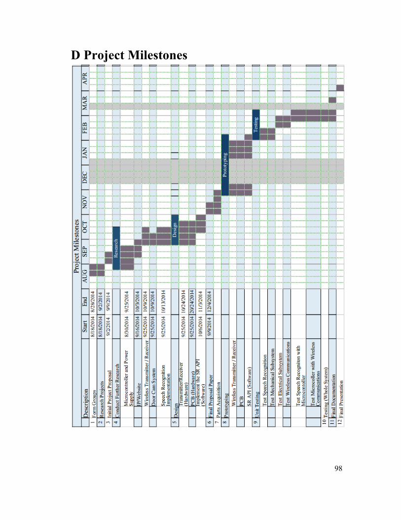
98
D Project Milestones

99
E Figures and Tables Index Table 1 - Project Specifications 5 Table 2 - Power Supply Specifications 8 Table 3 - AC/DC Power Adapter Specifications 9 Table 4 - Comparison of Single Supply Op Amplifiers 10-11 Table 5 - Electrical Specifications for P2N2222A transistor 12 Table 6 - Mechanical Specifications for the Servos 13 Table 7 - Electrical Specifications for the Servos 13 Table 8 - Control Specifications for the Servos 14 Table 9 - Electrical Specifications for TIP120 Darlington transistor 15 Table 10 - Comparison for Relay Units 16 Table 11 - Specifications for the Panasonic JT-N Power Relay 18 Table 12 - Speech Recognition IC (HM2007) 24 Table 13 - 64 KB External SRAM (HM6264B IC) 25 Table 14 - Octal Latch IC (74HC573) Specifications 26 Figure 1 - Light Control Module Interface 35 Figure 2 - Door Control Module Interface 36 Figure 3 - Door Unit Diagram 41 Figure 4 - Light Module Diagram 43 Figure 5 - ODROID-C1 in the initial version of the main enclosure 45 Figure 6 - CC3200 Simplified UML Diagram 46 Figure 7 - Texas Instruments CC3200 and Functional Block Diagram 46 Table 15 - CC3200 Operating Conditions 47 Figure 8 - Communication Procedure for CC3200 Network Processor Subsystem 49 Figure 9 - Basic Networking Application State Machine 50 Table 16 - Description of HM 2007 Pinout 52 Figure 10 - HM 2007 IC 52 Figure 11 - HM 2007 Keypad 53 Table 17 - Recognition Mode Format 54 Table 18 - Possible States 54 Table 19 - Commands Available 55 Table 20 - Read Operations 55 Table 21 - Standards Used in SCREAM 56 Figure 12 - Speech Recognition Subsystem 57 Figure 13 - Main Unit Breadboarding 58 Figure 14 - Polling Block Diagram 59 Figure 15 - HM2007 Recognizing a Command Flowpath 60 Figure 16 - HM2007 Training a Command Flowpath 61 Figure 17 - HM2007 Result Command Flowpath 62 Table 22 - Parts Acquisition Table 64 Table 23 - BOM for the Headset 64 Table 24 - BOM for the Main Unit 64 Table 25 - BOM for the Door Unit 66 Table 26 - BOM for the Power Control Unit 67

100
Figure 18 – Main Module PCB 68 Figure 19 – Light Module PCB 68 Figure 20 – Door Module PCB 69 Figure 21 - Steps to Establishing the ODROID as a Software AP 70 Figure 22 - Wireshark 802.11 Preferences 74 Figure 23 - Example TCP Packet Dissection in Wireshark 74 Figure 24 - Actual Wireshark Packet Capture from SCREAM 75 Figure 25 - Dataflow for the packet sniffer (SoC) 76 Table 27 - Software Tests 78 Table 28 - Device Power Modes 79 Figure 26 - Presentation Environment Layout 84 Table 29 - Original Budget 86 Table 30 - Complete Projected Budget 87