Embed Size (px)
Citation preview
Contents lists available at ScienceDirect
Applied Energy
journal homepage: www.elsevier.com/locate/apenergy
Screen-printed radial structure micro radioisotope thermoelectric generator
Zicheng Yuana, Xiaobin Tanga,b,⁎, Zhiheng Xua, Junqin Lia, Wang Chena, Kai Liua, Yunpeng Liua,b,Zhengrong Zhanga
a Department of Nuclear Science and Engineering, Nanjing University of Aeronautics and Astronautics, Nanjing 211106, Chinab Jiangsu Key Laboratory of Material and Technology for Energy Conversion, Nanjing 211106, China
H I G H L I G H T S
• The prototype of the micro radio-isotope thermoelectric generator wasfabricated by screen printing.
• The matching scheme of the thermo-electric leg material is compared.
• Three types of radioactive isotopeswere considered for experiments.
• 5 pairs of thermoelectric legs has anVoc of 68.41mV, Isc of 328.96 μA andan Pmax of 5.81 μW.
G R A P H I C A L A B S T R A C T
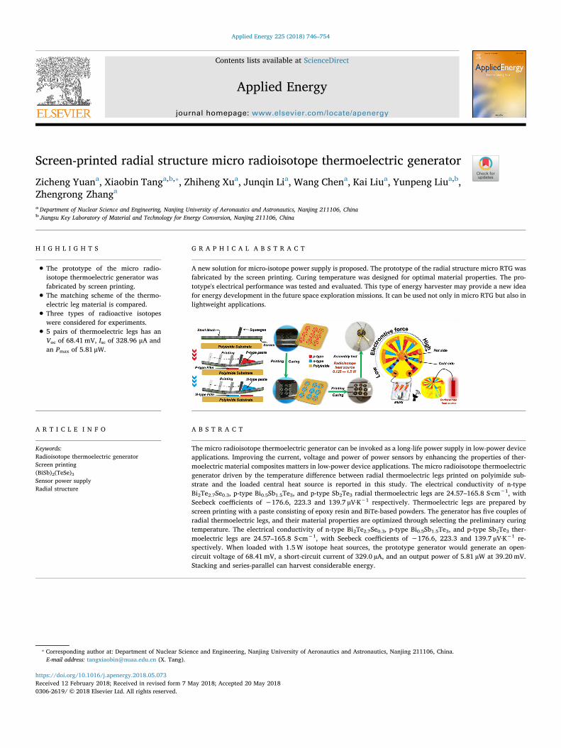
A new solution for micro-isotope power supply is proposed. The prototype of the radial structure micro RTG wasfabricated by the screen printing. Curing temperature was designed for optimal material properties. The pro-totype's electrical performance was tested and evaluated. This type of energy harvester may provide a new ideafor energy development in the future space exploration missions. It can be used not only in micro RTG but also inlightweight applications.
A R T I C L E I N F O
Keywords:Radioisotope thermoelectric generatorScreen printing(BiSb)2(TeSe)3Sensor power supplyRadial structure
A B S T R A C T
The micro radioisotope thermoelectric generator can be invoked as a long-life power supply in low-power deviceapplications. Improving the current, voltage and power of power sensors by enhancing the properties of ther-moelectric material composites matters in low-power device applications. The micro radioisotope thermoelectricgenerator driven by the temperature difference between radial thermoelectric legs printed on polyimide sub-strate and the loaded central heat source is reported in this study. The electrical conductivity of n-typeBi2Te2.7Se0.3, p-type Bi0.5Sb1.5Te3, and p-type Sb2Te3 radial thermoelectric legs are 24.57–165.8 S·cm−1, withSeebeck coefficients of −176.6, 223.3 and 139.7 µV·K−1 respectively. Thermoelectric legs are prepared byscreen printing with a paste consisting of epoxy resin and BiTe-based powders. The generator has five couples ofradial thermoelectric legs, and their material properties are optimized through selecting the preliminary curingtemperature. The electrical conductivity of n-type Bi2Te2.7Se0.3, p-type Bi0.5Sb1.5Te3, and p-type Sb2Te3 ther-moelectric legs are 24.57–165.8 S·cm−1, with Seebeck coefficients of −176.6, 223.3 and 139.7 µV·K−1 re-spectively. When loaded with 1.5W isotope heat sources, the prototype generator would generate an open-circuit voltage of 68.41mV, a short-circuit current of 329.0 µA, and an output power of 5.81 µW at 39.20mV.Stacking and series-parallel can harvest considerable energy.
https://doi.org/10.1016/j.apenergy.2018.05.073Received 12 February 2018; Received in revised form 7 May 2018; Accepted 20 May 2018
⁎ Corresponding author at: Department of Nuclear Science and Engineering, Nanjing University of Aeronautics and Astronautics, Nanjing 211106, China.E-mail address: [email protected] (X. Tang).
Applied Energy 225 (2018) 746–754
0306-2619/ © 2018 Elsevier Ltd. All rights reserved.
T
1. Introduction
The radioisotope thermoelectric generator (RTG) converting radio-isotope heat into electric power by thermoelectric (TE) materialwithout moving parts has numerous advantages, such as high relia-bility, long lifetime, and minimal environmental impact [1–4]. Theincreasing number of small spacecraft and studies on potential scientificapplications indicates the need for RTG application at low power levels.Micro RTGs (MRTGs) mainly lend themselves to small, long-life powerdevices. Moreover, MRTG can provide stable long-term power outputfor low-power sensing devices when carrying out deep space missions[5]. The application range of miniature scientific instruments, for ex-ample, the small long-life meteorological/seismological stations dis-tributed across planetary surfaces, subsurface probes, deep space micro-spacecrafts and sub-satellites, is very likely to extend due to such powersupply [4]. However, the minor temperature difference, low efficiencyand insufficient reliability of the miniaturized RTG currently limit itsapplication in space missions. As regard to the output performanceproblem of RTG, a novel micro RTG is designed to improve the aboveshortcomings in this paper.
TE modules in RTG can convert the energy between heat energy andelectric energy directly, diversely applied in harvesting and sensingenergy at the same time [6,7]. The optimization of structure and ma-terial is important to the properties of thermoelectric devices [8].Whalen et al. have used 11 pairs of 215 µm-thick Bi2Te3 in the design ofa wheel spoke thermocouple, and optimized the thermopile throughcutting the thermoelectric material by four equal parts. [9]. Menonet al. have stacked 15p–n radial TE couples in series, and further ob-tained the voltage and power increasing in linear along with TE[10,11]. The application of block and thick-film devices with thisstructure has been reported in previous work. The number of elementsand power in a given area needs to be balanced [12,13]. Semiconductoralloy materials based on Bi2Te3 have the brittleness characteristics[14]. In particular, the devices of long-life micro radioisotope of TEGsbased on printed thick film BiTe requires a high degree of mechanicalstability and flexibility. Physical cutting methods can no longer meetthe thin film requirements for fabricating devices with radial structures.Thus methods of molding the thick film TE material need to bechanged. As for the 2D additive manufacturing method, the screenprinting has the advantages of low cost, rapid prototyping and massmanufacturing. Son and Cho et al. have applied the screen printingmethod to produce high-performance thermoelectric generator by usingall-inorganic and hybrid viscoelastic inks in recent years [15–17]. Alarge number of thermocouples can be manufactured rapidly by screenprinting, able to provide high electric power, which is indeed a devel-oped and appropriate program [18,19]. RTG's reliability is similar tothe requirements on flexibility and output performance of a wearablethermoelectric device [20–22]. Polymer thermoelectric composite
materials are very attractive owing to its low cost, flexibility and highpower density [23]. Madan et al. have reported a flexible thermo-electric generator of polymer thermoelectric composite, used in flexibleand high output practical wireless sensor networks [24]. Gima et al.have reported 50-couple screen printed Bi2Te3/Bi0.5Sb1.5Te3-epoxyannular thermoelectric generators, used in ultra-low-power sensors,with the average power of 0.068 nW at a 20 K temperature gradient,26nA and 2.6mV [25]. In this study, we have investigated the TEproperties of MRTG composite materials. In addition, a new manu-facturing process is optimized, and the properties of the compositesemiconductor material are explored. Furthermore, a prototype withfive pairs of TE legs, diameter of 1.5 cm, and an area of 1.77 cm2 isprepared. It is tested by loading a radioisotope heat source. The outputperformance of the MRTG is further evaluated.
Moreover, it will improve the energy conversion efficiency by fab-ricating planar array and space stack thermoelectric devices. Thus, thethermoelectric device technology deserves to be promoted because ofthe simple heat treatment process, equipment manufacturing process,heat treatment conditions, and the whole process posing no harm to theenvironment. The use of new thermoelectric device manufacturingtechnology is not limited to micro RTG. Various lightweight devices,such as low-cost flexible wearable generators, solar thermal generatorsand pipe powering wireless sensors are also welcomed [20,26].
2. Materials and methods
2.1. Bi2Te3–epoxy TE paste synthesis
TE bulk ingots are prepared as TE powder (i.e., p-type Bi0.5Sb1.5Te3,Sb2Te3 and n-type Bi2Te2.7Se0.3) through airflow milling. The powderneeds to be sieved through a 325 mesh screen before use. The polymerbinder is an epoxy system formulated by the polypropylene glycol di-glycidyl ether epoxy resin (Sigma-Aldrich) and the methylhexahy-drophthalic anhydride (Sigma-Aldrich). Among them, the equivalentweight ratio of epoxy and hardener is 1:0.85. Furthermore, use the 1-Cyanoethyl-2-ethyl-4-methylimidazole (0.5 wt%; Shikoku Chemicals)as the catalyst in the system.
The TE powder occupies 45–50 vol% of and paste (Fig. S1). Add thebutyl acetate (Sigma-Aldrich) to the resin blend to reduce the viscosityof the ink as a nonreactive diluent. Furthermore, the low percentages oforganic solvents are used to extend the shelf life of the epoxy system soas to adjust the viscosity for printing, and the epoxy system is selectedin this work owing to its low viscosity and extended pot life. Use theplanetary mixer to mix the powder and solvent cement uniformly. Mixthe turbid liquid system at 1000 rpm for 3min, being held for 1min,and mix it again at 1800 rpm for 3min.
Nomenclature
σ electrical conductivity (S·m−1)n carrier concentration (cm−3)e quantity of electric chargeμ carrier mobility (cm2·V−1·s−1)S seebeck coefficient (μV·K−1)kB Boltzmann constanth Planck's constant
∗m effective mass of the carrierT absolute temperature (K)PF power fator (W·m−1·K−2)α seebeck coefficient (μV·K−1)
VΔ voltage difference (V)Vc cold-side voltage (V)
Vh hot-side voltage (V)TΔ temperature difference (K)
Th temperature of hot end (K)Tc temperature of cold end (K)Voc open-circuit voltage (V)Isc short-circuit current (A)N the number of thermoelectric legsαp p-type Seebeck coefficient (μV·K−1)αn n-type Seebeck coefficient (μV·K−1)Pth radioisotope thermal power (W)Pmax maximum output power (W)Rint internal resistance (Ω)Rload load resistance (Ω)TE thermoelectric
Z. Yuan et al. Applied Energy 225 (2018) 746–754
747
2.2. Device structure fabrication by screen printing
The steel mesh aperture is 200 mesh. The square samples are formedthrough successively curing the printed p-type, n-type, and electrode onthe polyimide film substrate at 90 °C for 2 h. Then, cure the squaresamples at various temperatures (i.e., 150 °C, 200 °C, 250 °C, 300 °C,and 350 °C) for 6 h in N2 atmosphere tube furnace to prevent oxidation.Further, print the shape of thermoelectric legs onto a fixed transparentsubstrate for printing visual alignment. TE legs used for device fabri-cation need to be cured twice. Moreover, fix the polyimide film sub-strate used for visual alignment before printing TE legs on a plate withpreprinted patterns. Then, cure the p-type TE legs at 90 °C for 2 h and300 °C for 6 h after being printed. After that, cut the samples used fordevice fabrication into round slices, and punch a hole at the center.Finally, the TE legs are cured at 90 °C for 2 h, and then 300 °C for 6 h.
The procedure usually involves printing, drying, printing, andcuring. However, the thermoelectric legs from the second printing isincomplete owing to the stickiness of paste, which causes strong re-sistance and even the non-conductivity [25]. Curing is thus divided intotwo steps: materials are cured after the first printing; materials do notadhere to the screen after the second printing, thereby the internalresistance of the generator is reduced.
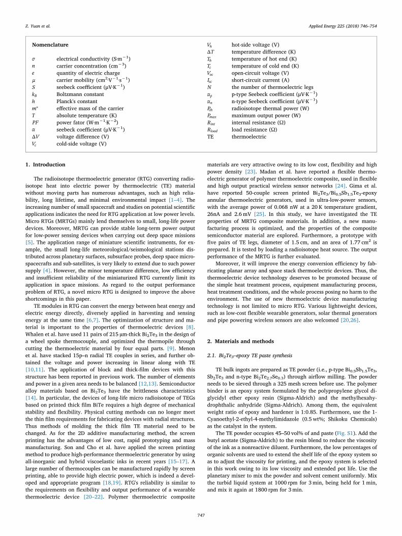
As shown in Fig. 1c, the prototype device comprises several ther-mocouples, among which, one thermocouple includes one n-type legand one p-type leg. This radial distribution structure enables thermalenergy to flux from the center of the heat source in a radial pattern, andthermal flux to flow from inside to outside through the thermocouples.Red and blue elements in the figure represent p-type and n-type TEsemiconductors respectively, and the temperature difference causeshole carriers and electron carriers in the semiconductor to diffuseoutside (cold side) from the center (hot end). The potential vectorpresents from inside to outside in p-type, which is opposite to that in n-type.
2.3. Radioisotope heat source
By the power density and mission time, the output of three typicalradioisotope heat sources is compared. According to the parameters ofthe isotope material, as listed in Table 1 [27], the heat source thermalpower could be calculated, then the simulation thermal power value ofthe surrogate heat source is obtained. The heat source power cannotexceed the power limit arising from the volume and power density.Thus, setting the thermal power as 0.125, 0.25, 0.5, 0.75, 1, and 1.5Wmay act as a reference for heat sources with different variety or purityin the experiment 2.3.
2.4. Characterization of TE thick film performance
Seebeck coefficient measurements of the printed TE films are con-ducted using a custom testing device. The Seebeck coefficient is de-termined according to the voltage difference (ΔV) and temperaturedifference (ΔT) curves obtained through using a multimeter (Agilent34970A Data Acquisition with 34901A 20 Channel Multiplexer,Agilent; Fig. S2). Electrical conductivity, carrier concentration, andmobility are obtained by using a Hall measurement system (HT-50,HONOR TOP). The magnetic flux density is 0.5 T, and the electricalcurrent is 15mA. X-ray diffraction (XRD) patterns are obtained throughusing a Cu Kα X-ray source at 40 kV and 40mA. Morphologies of thematerials are imaged through using a Quanta 650 FEG scanning elec-tron microscope (SEM; Thermo Fisher Scientific, USA) operating at15 kV. During SEM measurements, EDS (X-act SDD detector, OxfordInstruments, UK) data are obtained so as to analyze the chemical ele-ments.
The square standard samples (70 µm×20mm×20mm (Fig. 2a))are used to test the electrical conductivity and conduct the Seebeckcoefficient measurements.
2.5. Measurement of MRTG application
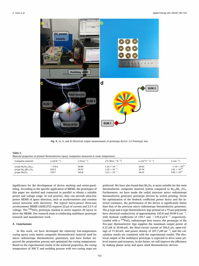
The heat source rod is loaded vertically into the hole, which is at thecenter of the radial TE leg samples. The lower part of the heat sourcebar is covered with foamed plastic to reduce heat loss. A resistive joulethermal surrogate is used in the MRTG to simulate a radioactive fuelpellet for experimental research (see Fig. 6). The power for the heatsource rods is provided by a programmable linear DC power supply(DP832A, RIGOL Technologies Inc.). The power range of 0–1.5W re-presents the three heat source columns, with the corresponding ruleshown in Table 2. J-type thermocouples are placed on the hot and coldsides of the prototype so as to monitor ΔT across the device. The MRTG
Fig. 1. Formation of TE thick films (a and b) and concept of MRTG (c).
Table 1Comparison of crucial radioisotope heat source material properties.
Parameters 238PuO290SrTiO3
241AmO2
Half-life of isotope (T1/2, year) 87.7 28.9 432.7Specific activity (Ci/g) 15 133 3.43Power per activity (µW/Ci) 32000.0 6665.92 32362.0Density (g/cm3) 11.5 5.11 13.67Initial volumetric power density (W/cm3) 5.52 4.54 1.52Heat source thermal power (W) 1.564 1.287 0.431
Z. Yuan et al. Applied Energy 225 (2018) 746–754
748
is connected to a parameter analyzer (Keithley 4200-SCS). I–V char-acteristics are measured using software KTEI (Keithley Test Environ-ment Interactive).
3. Result and discussion
3.1. Material properties of screen-printed TE thick films
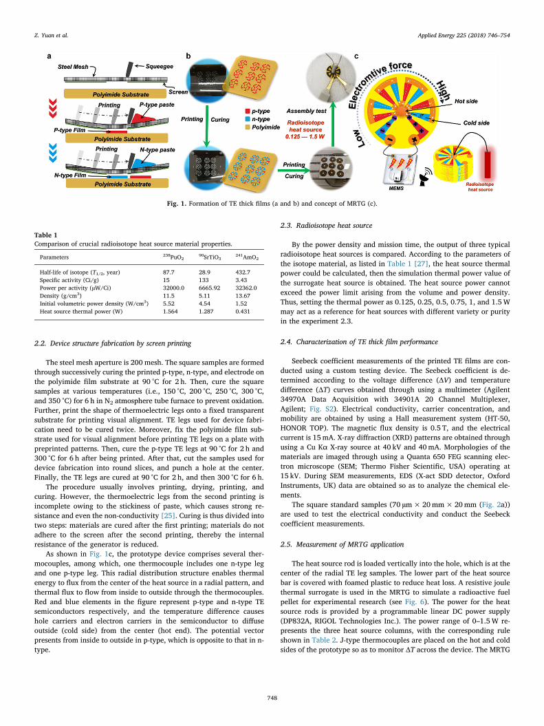
Fig. 2b-d shows the XRD spectra of the n-type Bi2Te2.7Se0.3, p-typeBi0.5Sb1.5Te3, and p-type Sb2Te3 samples, prepared by increasing thecuring temperature from 150 °C to 300 °C. The XRD peaks of the sam-ples can be indexed to the corresponding JCPDF crystal samples (i.e.,JCPDF Nos. 50-0954, 49-1713, and 71-0393). Element types and con-tent are consistent with TE powder and epoxy resin (Fig. S3).
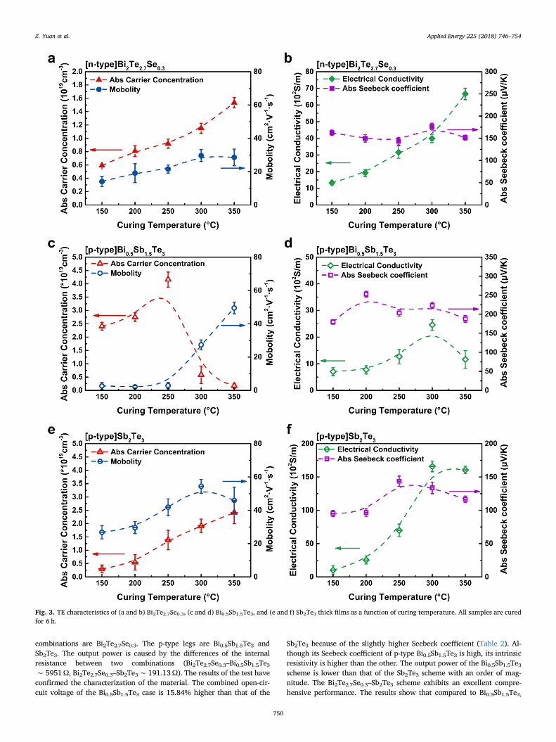
Fig. 3 shows the function relationship of curing temperature and theTE properties of composite films measured at room temperature. Thefigure shows the carrier concentration of the three TE composite films.The carrier concentration of Bi2Te2.7Se0.3 and Sb2Te3 increases alongwith the increased temperature, and the opposite for Bi0.5Sb1.5Te3 afterthe temperature is more than 250 °C. The Seebeck coefficient of a si-milar metal-doped degenerate semiconductor may be affected by thecarrier concentration. Thus these properties will affect the TE proper-ties of the material.
=σ neμ (1)
= ⎛⎝
⎞⎠
∗Sπ keh
m T πn
83 3
B2 2
2
2/3
(2)
The relationship between Seebeck coefficient and power factor areshown in TE characteristics of (a and b) Bi2Te2.7Se0.3, (c and d)Bi0.5Sb1.5Te3, and (e and f) Sb2Te3 thick films as a function of curingtemperature. All samples are cured for 6 h. Fig. 3b, d, and f, and theirvalues are obtained according to the following equation:
= −V V VΔ ,c h (3)
= −T T TΔ ,h c (4)
= = →α VT
VT
dd
lim ΔΔ
,TΔ 0 (5)
=PF α σ.2 (6)
The conductivity will be determined by the carrier concentrationand mobility along with the change in curing temperature [28–30].Hall effect tests reflect that mobility increases more slowly than carrierconcentration. In the low-temperature curing process, the contributionof carrier concentration to conductivity is significant. The variation ofthe Seebeck coefficient is different from that of high-temperature sin-tering, and a trend of monotonic decrease with the carrier concentra-tion is not observed. These resin composite TE materials may have lostthe performance of degenerate semiconductors. Because Bi0.5Sb1.5Te3has a high melting point and low electrical conductivity, the con-ductivity of the composite material system is lower than that of theothers though its Seebeck voltage is higher than that of the other(Fig. 4a). Property variation of Sb2Te3 in this study is consistent withthat in similar research [31,32]. In fact, the samples cured with tem-perature above 300 °C have a high fragmentation rate after incineratingthe cured epoxy resin. Given the power factor (Fig. 4b), p-type Sb2Te3and n-type Bi2Te2.7Se0.3 at 300 °C should be the preferred solution.
The slope of the ΔT–ΔV function (Fig. 4a) represented the values ofthe Seebeck coefficients of n-type Bi2Te2.7Se0.3, p-type Bi0.5Sb1.5Te3,and p-type Sb2Te3 (cured at 300 °C) of −176.6, 223.3, and139.7 µV K−1, respectively. The square standard samples(70 µm×20mm×20mm) are cured at 300 °C for 6 h after beingcured at 90 °C.
3.2. TE legs case of MRTG
A comparison of the experimental output performance of two com-binations is shown in Fig. 5. The n-type TE legs amid the two
Fig. 2. (a) TE paste printed in various shapes with radial TE legs and square samples. X-ray diffraction (XRD) patterns of screen-printed (b) n-type Bi2Te2.7Se0.3, (c) p-type Bi0.5Sb1.5Te3, and (d) p-type Sb2Te3 samples with different curing temperatures. Insets show that the XRD pattern is indexed to the corresponding JCPDF.
Z. Yuan et al. Applied Energy 225 (2018) 746–754
749
combinations are Bi2Te2.7Se0.3. The p-type legs are Bi0.5Sb1.5Te3 andSb2Te3. The output power is caused by the differences of the internalresistance between two combinations (Bi2Te2.7Se0.3–Bi0.5Sb1.5Te3∼ 5951Ω, Bi2Te2.7Se0.3–Sb2Te3∼ 191.13Ω). The results of the test haveconfirmed the characterization of the material. The combined open-cir-cuit voltage of the Bi0.5Sb1.5Te3 case is 15.84% higher than that of the
Sb2Te3 because of the slightly higher Seebeck coefficient (Table 2). Al-though its Seebeck coefficient of p-type Bi0.5Sb1.5Te3 is high, its intrinsicresistivity is higher than the other. The output power of the Bi0.5Sb1.5Te3scheme is lower than that of the Sb2Te3 scheme with an order of mag-nitude. The Bi2Te2.7Se0.3–Sb2Te3 scheme exhibits an excellent compre-hensive performance. The results show that compared to Bi0.5Sb1.5Te3,
Fig. 3. TE characteristics of (a and b) Bi2Te2.7Se0.3, (c and d) Bi0.5Sb1.5Te3, and (e and f) Sb2Te3 thick films as a function of curing temperature. All samples are curedfor 6 h.
Z. Yuan et al. Applied Energy 225 (2018) 746–754
750
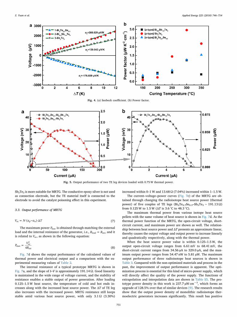
Sb2Te3 is more suitable for MRTG. The conductive epoxy silver is not usedas connection electrode, but the TE material itself is connected to theelectrode to avoid the catalyst poisoning effect in this experiment.
3.3. Output performance of MRTG
= −V N α α T·( )·Δp noc (7)
The maximum power Pmax is obtained through matching the externalload and the internal resistance of the generator, i.e., =R Rload int, and itis related to Voc, as shown in the following equation:
=PVR4max
oc2
int (8)
Fig. 7d shows the output performance of the calculated values ofthermal power and electrical output and a comparison with the ex-perimental measuring values of Table 2.
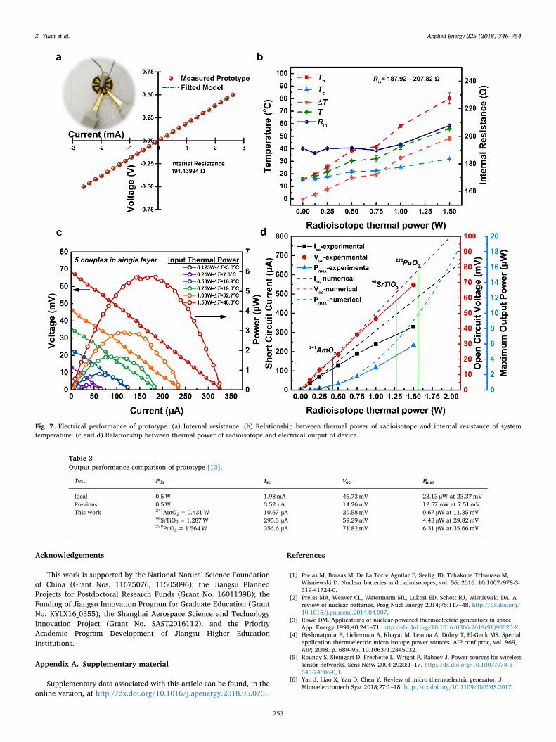
The internal resistance of a typical prototype MRTG is shown inFig. 7a, and the slope of I–V is approximately 191.14Ω. Good linearityis maintained in the wide range of voltage current, and the stability ofresistance enables a stable output of power generation. After loading0.125–1.5W heat source, the temperature of cold and hot ends in-creases along with the increased heat source power. The ΔT of TE legalso increases with the increased power. MRTG resistance still keepsstable amid various heat source power, with only 3.1Ω (3.30%)
increased within 0–1W and 13.68Ω (7.04%) increased within 1–1.5W.The current–voltage–power curves (Fig. 7c) of the MRTG are ob-
tained through changing the radioisotope heat source power (thermalpower) of five couples of TE legs (Bi2Te2.7Se0.3–Sb2Te3∼ 191.13Ω)from 0.125W to 1.5W (ΔT is 3.6 °C to 48.3 °C).
The maximum thermal power from various isotope heat sourcepellets with the same volume of heat source is shown in Fig. 7d. As thethermal power function of the MRTG, the open-circuit voltage, short-circuit current, and maximum power are shown as well. The relation-ship between heat source power and ΔT presents an approximate linear,thereby causes the output voltage and output power to increase linearlyand quadratically respectively, along with the thermal power.
When the heat source power value is within 0.125–1.5W, theoutput open-circuit voltage ranges from 6.61mV to 68.41mV, theshort-circuit current ranges from 34.56 µA to 329.0 µA, and the max-imum output power ranges from 54.47 nW to 5.81 µW. The maximumoutput performance of three radioisotope heat sources is shown inTable 3. Compared with the non-optimized materials and process in thepast, the improvement of output performance is apparent. The opti-mization process is essential for this kind of micro-power supply, whichwill directly affect the quality of the power supply. The functions ofextrapolation and interpolation data are shown in Table S5. The pro-totype power density in this work is 237.7 µW cm−3, which forms anupgrade of 128.5% over that of similar devices [9]. The research resultsshow that the output power density of monolithic radioisotope ther-moelectric generators increases significantly. This result has positive
Fig. 4. (a) Seebeck coefficient. (b) Power factor.
Fig. 5. Output performance of two TE leg devices loaded with 0.75W thermal power.
Z. Yuan et al. Applied Energy 225 (2018) 746–754
751
significance for the development of device stacking and series-paral-leling. According to the specific application of MEMS, the prototypes ofthis paper are stacked and connected in parallel to obtain a suitablepower and voltage range. In real practice, they can provide ultra-lowpower MEMS of space detectors, such as accelerometers and wirelesssensor networks with electricity. The typical micro-power three-axisaccelerometer MEMS (ADXL372) requires 22 µA of current and 2.5 V ofvoltage. The 238PuO2 prototype stacked in series requires 36 layers todrive the MEMS. Our research team is conducting multilayer prototyperesearch and manufacture work.
4. Conclusions
In this work, we have developed the relatively low-temperaturecuring epoxy resin matrix composite thermoelectric material used formicro radioisotope thermoelectric generators, and have further im-proved the preparation process and optimized the curing temperature.Based on the experimental results of the material properties, the curingtemperature of 300 °C and molding process with two curing steps are
preferred. We have also found that Sb2Te3 is more suitable for the resinthermoelectric composite material system compared to Bi0.5Sb1.5Te3.Furthermore, we have made the radial structure micro radioisotopethermoelectric generator prototype devices by screen printing. Giventhe optimization of the Seebeck coefficient power factor and the in-ternal resistance, the performance of the device is significantly betterthan that of the previous micro radioisotope thermoelectric generator.The p-type and n-type thermoelectric legs printed on a 75 µm polyimidehave electrical conductivity of approximately 165.8 and 39.89 S cm−1,with Seebeck coefficients of 139.7 and −176.6 µV K−1 respectively.Loaded with a 238PuO2 radioisotope heat source, the prototype of thefive-pair thermoelectric legs supplies the maximum output power of6.31 µW at 35.66mV, the short-circuit current of 356.6 µA, open-vol-tage of 71.82mV, and power density of 237.7 µW cm−3, and the cal-culation results are consistent with the experimental results. The elec-trical output of the multilayer prototype is expected to drive some µA-level sensors and actuators. In the future, we will improve the efficiencyby making planar array and space stack thermoelectric devices.
Fig. 6. (a, b, and d) Electrical output measurement of prototype device. (c) Prototype size.
Table 2Material properties of printed thermoelectric/epoxy composites measured at room temperature.
Composite material α (µV·K−1) σ (S·cm−1) α2σ (W·m−1·K−2) μ (cm2·V−1·s−1) n (cm−3)
n-type Bi2Te2.7Se0.3 −176.6 39.89 1.24× 10⁻⁴ 29.63 −1.15×10¹⁹
p-type Bi0.5Sb1.5Te3 223.3 24.57 1.23× 10⁻⁴ 27.34 1.91× 10¹⁹
p-type Sb2Te3 139.7 165.8 3.21× 10⁻⁴ 54.41 5.85× 10¹⁸
Z. Yuan et al. Applied Energy 225 (2018) 746–754
752
Acknowledgements
This work is supported by the National Natural Science Foundationof China (Grant Nos. 11675076, 11505096); the Jiangsu PlannedProjects for Postdoctoral Research Funds (Grant No. 1601139B); theFunding of Jiangsu Innovation Program for Graduate Education (GrantNo. KYLX16_0355); the Shanghai Aerospace Science and TechnologyInnovation Project (Grant No. SAST2016112); and the PriorityAcademic Program Development of Jiangsu Higher EducationInstitutions.
Appendix A. Supplementary material
Supplementary data associated with this article can be found, in theonline version, at http://dx.doi.org/10.1016/j.apenergy.2018.05.073.
References
[1] Prelas M, Boraas M, De La Torre Aguilar F, Seelig JD, Tchakoua Tchouaso M,Wisniewski D. Nuclear batteries and radioisotopes, vol. 56; 2016. 10.1007/978-3-319-41724-0.
[2] Prelas MA, Weaver CL, Watermann ML, Lukosi ED, Schott RJ, Wisniewski DA. Areview of nuclear batteries. Prog Nucl Energy 2014;75:117–48. http://dx.doi.org/10.1016/j.pnucene.2014.04.007.
[3] Rowe DM. Applications of nuclear-powered thermoelectric generators in space.Appl Energy 1991;40:241–71. http://dx.doi.org/10.1016/0306-2619(91)90020-X.
[4] Heshmatpour B, Lieberman A, Khayat M, Leanna A, Dobry T, El-Genk MS. Specialapplication thermoelectric micro isotope power sources. AIP conf proc, vol. 969,AIP; 2008. p. 689–95. 10.1063/1.2845032.
[5] Roundy S, Steingart D, Frechette L, Wright P, Rabaey J. Power sources for wirelesssensor networks. Sens Netw 2004;2920:1–17. http://dx.doi.org/10.1007/978-3-540-24606-0_1.
[6] Yan J, Liao X, Yan D, Chen Y. Review of micro thermoelectric generator. JMicroelectromech Syst 2018;27:1–18. http://dx.doi.org/10.1109/JMEMS.2017.
Fig. 7. Electrical performance of prototype. (a) Internal resistance. (b) Relationship between thermal power of radioisotope and internal resistance of systemtemperature. (c and d) Relationship between thermal power of radioisotope and electrical output of device.
Table 3Output performance comparison of prototype [13].
Test Pth Isc Voc Pmax
Ideal 0.5W 1.98mA 46.73mV 23.13 µW at 23.37mVPrevious 0.5W 3.52 µA 14.26mV 12.57 nW at 7.51mVThis work 241AmO2=0.431W 10.67 µA 20.58mV 0.67 µW at 11.35mV
90SrTiO3= 1.287W 295.3 µA 59.29mV 4.43 µW at 29.82mV238PuO2= 1.564W 356.6 µA 71.82mV 6.31 µW at 35.66mV
Z. Yuan et al. Applied Energy 225 (2018) 746–754
753
2782748.[7] Wang Y, Shi Y, Mei D, Chen Z. Wearable thermoelectric generator to harvest body
heat for powering a miniaturized accelerometer. Appl Energy 2018;215:690–8.http://dx.doi.org/10.1016/j.apenergy.2018.02.062.
[8] Kim CS, Lee GS, Choi H, Kim YJ, Yang HM, Lim SH, et al. Structural design of aflexible thermoelectric power generator for wearable applications. Appl Energy2018;214:131–8. http://dx.doi.org/10.1016/j.apenergy.2018.01.074.
[9] Whalen SA, Apblett CA, Aselage TL. Improving power density and efficiency ofminiature radioisotopic thermoelectric generators. J Power Sour 2008;180:657–63.http://dx.doi.org/10.1016/j.jpowsour.2008.01.080.
[10] Menon AK, Meek O, Eng AJ, Yee SK. Radial thermoelectric generator fabricatedfrom n- and p-type conducting polymers. J Appl Polym Sci 2017;134. http://dx.doi.org/10.1002/app.44060.
[11] Menon AK, Yee SK. Design of a polymer thermoelectric generator using radial ar-chitecture. J Appl Phys 2016;119. http://dx.doi.org/10.1063/1.4941101.
[12] Liu K, Liu Y, Xu Z, Zhang Z, Yuan Z, Guo X, et al. Experimental prototype andsimulation optimization of micro-radial milliwatt-power radioisotope thermo-electric generator. Appl Therm Eng 2017;125:425–31. http://dx.doi.org/10.1016/j.applthermaleng.2017.07.022.
[13] Yuan Z, Tang X, Liu Y, Xu Z, Liu K, Zhang Z, et al. A stacked and miniaturizedradioisotope thermoelectric generator by screen printing. Sens Actuators A Phys2017;267:496–504. http://dx.doi.org/10.1016/j.sna.2017.10.055.
[14] Russo V, Bailini A, Zamboni M, Passoni M, Conti C, Casari CS, et al. Raman spec-troscopy of Bi-Te thin films. J Raman Spectrosc 2008;39:205–10. http://dx.doi.org/10.1002/jrs.1874.
[15] Kim SJ, We JH, Cho BJ. [15] A wearable thermoelectric generator fabricated on aglass fabric. Energy Environ Sci 2014;7:1959. http://dx.doi.org/10.1039/c4ee00242c.
[16] We JH, Kim SJ, Cho BJ. Hybrid composite of screen-printed inorganic thermo-electric film and organic conducting polymer for flexible thermoelectric powergenerator. Energy 2014;73:506–12. http://dx.doi.org/10.1016/j.energy.2014.06.047.
[17] Kim F, Kwon B, Eom Y, Lee JE, Park S, Jo S, et al. 3D printing of shape-conformablethermoelectric materials using all-inorganic Bi2Te3-based inks. Nat Energy 2018.http://dx.doi.org/10.1038/s41560-017-0071-2.
[18] Park SH, Jo S, Kwon B, Kim F, Ban HW, Lee JE, et al. High-performance shape-engineerable thermoelectric painting. Nat Commun 2016;7. http://dx.doi.org/10.1038/ncomms13403.
[19] Varghese T, Hollar C, Richardson J, Kempf N, Han C, Gamarachchi P, et al. High-performance and flexible thermoelectric films by screen printing solution-processednanoplate crystals. Sci Rep 2016;6. http://dx.doi.org/10.1038/srep33135.
[20] Jung YS, Jeong DH, Kang SB, Kim F, Jeong MH, Lee KS, et al. Wearable solar
thermoelectric generator driven by unprecedentedly high temperature difference.Nano Energy 2017;40:663–72. http://dx.doi.org/10.1016/j.nanoen.2017.08.061.
[21] Hyland M, Hunter H, Liu J, Veety E, Vashaee D. Wearable thermoelectric generatorsfor human body heat harvesting. Appl Energy 2016;182:518–24. http://dx.doi.org/10.1016/j.apenergy.2016.08.150.
[22] Lu Z, Zhang H, Mao C, Li CM. Silk fabric-based wearable thermoelectric generatorfor energy harvesting from the human body. Appl Energy 2016;164:57–63. http://dx.doi.org/10.1016/j.apenergy.2015.11.038.
[23] Siddique ARM, Mahmud S, Van Heyst B. A review of the state of the science onwearable thermoelectric power generators (TEGs) and their existing challenges.Renew Sustain Energy Rev 2017;73:730–44. http://dx.doi.org/10.1016/j.rser.2017.01.177.
[24] Madan D, Wang Z, Wright PK, Evans JW. Printed flexible thermoelectric generatorsfor use on low levels of waste heat. Appl Energy 2015;156:587–92. http://dx.doi.org/10.1016/j.apenergy.2015.07.066.
[25] Gima ZT, Gururangan K, Evans J, Wright P. Annular screen printed thermoelectricgenerators for ultra-low-power sensor applications. J Phys: Conf Ser 2016;773.http://dx.doi.org/10.1088/1742-6596/773/1/012115.
[26] Iezzi B, Ankireddy K, Twiddy J, Losego MD, Jur JS. Printed, metallic thermoelectricgenerators integrated with pipe insulation for powering wireless sensors. ApplEnergy 2017;208:758–65. http://dx.doi.org/10.1016/j.apenergy.2017.09.073.
[27] Cheon SJ, Hong SG, Lee JH, Nam YS. Design and performance analysis of a 500-Wheat source for radioisotope thermophotovoltaic converters. Int J Energy Res2017:1–13. http://dx.doi.org/10.1002/er.3889.
[28] Madan D, Wang Z, Chen A, Wright PK, Evans JW. High-performance dispenserprinted MA p-type Bi0.5Sb 1.5Te3 flexible thermoelectric generators for poweringwireless sensor networks. ACS Appl Mater Interf 2013;5:11872–6. http://dx.doi.org/10.1021/am403568t.
[29] Madan D, Wang Z, Chen A, Juang RC, Keist J, Wright PK, et al. Enhanced perfor-mance of dispenser printed MA n-type Bi2Te3composite thermoelectric generators.ACS Appl Mater Interf 2012;4:6117–24. http://dx.doi.org/10.1021/am301759a.
[30] Choi H, Kim SJ, Kim Y, We JH, Oh M-W, Cho BJ. Enhanced thermoelectric prop-erties of screen-printed Bi0.5Sb1.5Te3 and Bi2Te2.7Se0.3 thick films using a postannealing process with mechanical pressure. J Mater Chem C 2017. http://dx.doi.org/10.1039/C7TC01797A.
[31] Cao Z, Tudor MJ, Torah RN, Beeby SP. Screen printable flexible BiTe-SbTe-basedcomposite thermoelectric materials on textiles for wearable applications. IEEETrans Electron Dev 2016;63:4024–30. http://dx.doi.org/10.1109/TED.2016.2603071.
[32] Madan D, Chen A, Wright PK, Evans JW. Dispenser printed composite thermo-electric thick films for thermoelectric generator applications. J Appl Phys 2011;109.http://dx.doi.org/10.1063/1.3544501.
Z. Yuan et al. Applied Energy 225 (2018) 746–754
754