Embed Size (px)
Citation preview
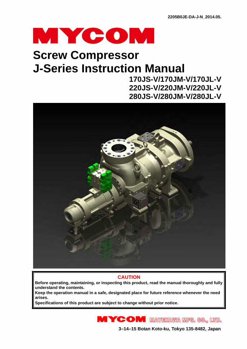
2205B0JE-DA-J-N_2014.05.
3–14–15 Botan Koto-ku, Tokyo 135-8482, Japan
Screw Compressor J-Series Instruction Manual
170JS-V/170JM-V/170JL-V 220JS-V/220JM-V/220JL-V 280JS-V/280JM-V/280JL-V
CAUTION Before operating, maintaining, or inspecting this product, read the manual thoroughly and fully understand the contents. Keep the operation manual in a safe, designated place for future reference whenever the need arises. Specifications of this product are subject to change without prior notice.
2205B0JE-DA-J-N_2014.05. Preface
Screw Compressor J-series
i
Preface Thank you for purchasing this J-series/screw compressor (hereinafter indicated as "this product").
This instruction manual (hereinafter indicated as "this manual") describes safety information, operational and maintenance procedures in detail for safe and effective use of this product、and applies to the following types. 170JS, 170JM, 170JL, 220JS, 220JM, 220JL, 280JS, 280JM, 280JL Before installing or using this product, make sure you read this manual.
Keep this manual in a safe place near the product for quick reference.
Revision History Instruction manual name Document No. First edition issue date
J-Series Instruction manual 2205B0JE-DA-J-N_2014.05. 2009.10.01
Revision No.
Issuance Date
Contents of revisions Created/
approved by:
17J0001 2010.03.15 Corrected editing error of Vi Position Sensor. Kobayashi
17J0002 2012.01.31 Addition of 220J/280J-series Kobayashi / Muta
03 2014.03.27 Revision by lubricating method change, other Muta/ Hirao
04 2014.04.25Replaced Figure 2-1, changed the unit of motor rotation speed to SI-unit
Ikehara / Muta
05 2014.05.21Corrected the description shortage of oil filter requirements at Section 3.2.5.3
Ikehara/ Kubota
2205B0JE-DA-J-N_2014.05. Warranty and Disclaimer
Screw Compressor J-series
ii
Warranty and Disclaimer
Warranty Clauses If malfunctions or damages occur under proper usage and conditions following documents such as specifications or instruction manual of this product, or, if MAYEKAWA judges that malfunctions or damages are related to design or manufacture of the product, and if the malfunctions or damages are within the warranty period, we will repair or replace the product without any charges.
The warranty period is “12 months from factory shipment of this product”. If use of this product is governed by any other contracts, they will be given priority.
Disclaimer Clauses (Exclusion of Warranty Clauses) Please note that we disclaim any responsibility for damage or malfunction to this product, as described in the following items.
Malfunction or damage of this product caused by natural disaster, or other accidental forces (such as windstorm, intense rainfall, flood, tidal wave, earthquake, land subsidence, thunderbolt, fire, etc.).
Malfunction, damage, or defect to this product due to abnormal or improper use (such as storing this product outdoors or in locations subject to high temperatures and high humidity, unexpected inspections, tests, operations, and excessive repetition of start-up/stoppage of the product.).
Malfunction or damage caused by devices or equipment not provided by MAYEKAWA including operation control methods of those devices.
Malfunction or damage caused by refrigerants, gases, or lubricants not approved for this product.
Malfunction or damage caused by maintenance or inspection not recommended by MAYEKAWA.
Malfunction or damage caused by parts that are not MAYEKAWA genuine.
Malfunction or damage caused by remodeling the product without the approval of MAYEKAWA.
Direct or indirect production warranty or all other related warranties that arose due to malfunction or damage of this product.
2205B0JE-DA-J-N_2014.05. Important Information
Screw Compressor J-series
iii
Important Information
Intended Use of This Product This product is a general-purpose screw compressor intended for refrigeration and cold storage.
Do not use the product for any purposes for which it was not intended or which depart from the specifications. For specifications of this product, refer to “2.3 Compressor Specifications”.
The maintenance items described in this manual should be performed safely and closely following procedures.
Important Information for Safe Use of This Product Although MAYEKAWA has paid a lot of attention to safety measures for this product, all hazards including potential hazards caused by human errors, or due to environmental conditions can not be anticipated.
There are guidelines that must be observed for operating this product. However, the warnings in this manual and safety labels on the product are not all inclusive. When operating this product, pay extreme caution on personnel safety as well as on items described in this manual.
Important rules for safety work with the product that apply to all workers including managers and supervisors are listed below.
Before using this product, carefully read and fully understand the contents written in this manual and pay attention to safety.
Operation, maintenance, and inspection of this product should be performed by qualified personnel educated about the fundamentals of the product and trained about hazards involved and measures to avoid danger.
Do not allow any person other than those educated on the fundamental expertise of the product and trained about hazards involved and measures to avoid dangers to approach the product while it is operating or during maintenance.
Observe all related federal/national and local codes and regulations.
To prevent accidents, do not carry out any operation or maintenance other than those described in this manual, or use the product for any unapproved purpose.
Replace the parts with the genuine parts.
Not only workers but also managers should actively participate safety and health activities in the workplace to prevent accidents.
When closing or opening valves during work, apply lockout/tagout without failure, to prevent the valves from closing or opening accidentally during the work.
[Lockout] To lock with a key in order to keep people, except the workers involved, from operating the product.
“Lockout” means disconnecting or keeping disconnected machines and devices by locking their energy (power) sources. Lockout is not just simply turning off the power switches to stop the supply of power, but includes immobilizing them with a key or similar device to keep any blocked switches from being operated.
Lockout devices are devices such as keys, covers, and latches, to immobilize switches, valves, opening and closing levers, etc., with a state of being locked.
[Tagout] To prevent any inappropriate work by hanging tag plates indicating “work in progress”.
“Tagout” means to clearly indicate, by hanging tag plates, that a device is in lockout and that operation of the device is prohibited. Tag plates forbidding operation, starting, opening, etc. are warnings clearly stating to not operate energy (power) sources, and are not for stopping blocking devices.
2205B0JE-DA-J-N_2014.05. Important Information
Screw Compressor J-series
iv
Observe the following precautions when performing maintenance work on electrical control.
Electrical maintenance of the product must be performed by certified/qualified personnel and only those educated about the electrical control of the product.
Before servicing or inspecting the electrical equipments or devices, turn "OFF" the motor main power and control power, and perform lockout/tagout to prevent the power from being turned on during work.
Even when the motor main power and control power are turned "OFF", this product may be turned on if the power is supplied from outside the refrigeration system, cold storage, and air conditioning unit. Make sure the power supply on the power source side is shut off, and perform lockout/tagout to prevent the product from being turned on during work.
About This Manual This product may be modified without prior notice. Therefore, the appearance of actual
machine may differ from the descriptions in this manual. If you have any questions contact your sales offices or service centers.
This manual is in English. If any other language is required it is the customers responsibility to prepare a manual for safety education and operation instructions.
This manual is copyrighted. Drawings and technical references including this manual shall not, in whole or part, be copied, photocopied, or reproduced into any electronic medium or machine-readable form without prior permission from MAYEKAWA.
Photographs or drawings included in this manual may differ from the appearance of actual product.
If this manual is lost or damaged, immediately place a purchase order to your local sales office or service center for a new manual. Using the product without the manual may result in safety issues.
If you resell the product, never fail to attach this manual to the product.
Construction of This Manual Tit le of section and
chapter Descript ion details
Preface Describes the outline of this manual and how to read the manual.
Warranty and Disclaimer Describes clauses and coverage of warranty. Exemption of warranty clauses is described as disclaimer.
Important Information Describes important information related to this product and this manual.
1. Safety Describes safety information for the worker, safety rules for this product, and management details regarding work safety required for handling the product.
2. Structure and Specifications of the Compressor
Describes the main components of this product, functional information, specifications, and operating limits.
3. Installation Describes installation procedure of this product. 4. Compressor and Package Operation
Describes precautions for operating this product.
5. Maintenance and Inspection Describes sections and period for inspecting, disassembly and assembly of the product.
6. Troubleshooting Describes troubleshooting methods for the product in case problems occur during operation of the product.
7. Related Documents Describes documents such as illustrated parts breakdown and parts list.
Appendix Describes tips for design, manufacturing, and installation of the compressor package.
Contact Information Describes contact information for our local sales offices or service centers, which are for ordering genuine parts.
2205B0JE-DA-J-N_2014.05. Table of Contents
Screw Compressor J-series
v
Table of Contents
Preface .................................................................................................................... ⅰ
Revision History ..................................................................................................... ⅰ
Warranty and Disclaimer ....................................................................................... ⅱ
Important Information ............................................................................................ ⅲ
Intended Use of This Product ........................................................................................... ⅲ
Important Information for Safe Use of This Product .......................................................... ⅲ
About This Manual ............................................................................................................. ⅳ
Construction of This Manual .............................................................................................. ⅳ
Table of Contents ................................................................................................... ⅴ
1 Safety 1.1 Observation/Prevention .............................................................................. 1-1
1.1.1 Observance (Do's) ............................................................................................ 1-1
1.1.1.1 Do's on Operation ........................................................................................ 1-1 1.1.1.2 Do's on Maintenance ................................................................................... 1-1 1.1.1.3 Do's on Lockout/Tagout after Shutting off the Power .................................. 1-2 1.1.1.4 Do's about Personal Protective Gear .......................................................... 1-2 1.1.1.5 Do's about Handling of Hazardous and Toxic Substances .......................... 1-2 1.1.1.6 Do's about Handling Emergency Situation .................................................. 1-2 1.1.1.7 Do's about Waste Oil, Fluid, and Materials ................................................. 1-2 1.1.1.8 Other Do's .................................................................................................... 1-3
1.1.2 Prohibition (Don'ts) ........................................................................................... 1-3
1.2 Warnings ....................................................................................................... 1-4 1.2.1 Types and Meanings of Warnings .................................................................... 1-4
1.2.2 Safety labels ..................................................................................................... 1-4
1.3 Residual Risks ............................................................................................. 1-7
1.4 Safety Devices ............................................................................................ 1-10 1.4.1 Emergency Stop Button .................................................................................. 1-10
1.4.2 Breakers of Main Motor Power and Control Power (Use of Lockout/Tagout Devices) ................................................................... 1-10
1.4.3 Compressor Protection Devices ..................................................................... 1-11
2 Structure and Specifications of the Compressor 2.1 Features of the J-Series Screw Compressor ............................................. 2-1
2.2 Model Designation of the Compressor ...................................................... 2-1
2.3 Compressor Specifications ........................................................................ 2-2 2.3.1 Specifications .................................................................................................... 2-2
2.3.2 Operation Limits ................................................................................................ 2-5
2.3.3 Outer Dimensions ............................................................................................. 2-7
2.4 Structure of the Compressor .................................................................... 2-14 2.4.1 Sectional View ................................................................................................ 2-15

2205B0JE-DA-J-N_2014.05. Table of Contents
Screw Compressor J-series
vi
2.5 Mechanisms ............................................................................................... 2-24 2.5.1 Basics of the Screw Compressor ................................................................... 2-24
2.5.2 Suction Process .............................................................................................. 2-25
2.5.3 Compression Process .................................................................................... 2-25
2.5.4 Discharge Process .......................................................................................... 2-25
2.6 Oil Flow ....................................................................................................... 2-26
2.7 Capacity Control Characteristics ............................................................. 2-27
2.8 Variable Vi Control ..................................................................................... 2-28 2.8.1 Vi (Internal Volume Ratio) .............................................................................. 2-28
2.8.2 Reasons for Adjusting Vi According to Operating Conditions ........................ 2-29
2.8.3 Details of Variable Vi Mechanism ................................................................... 2-29
2.8.3.1 Automatic Variable Vi Mode ...................................................................... 2-29 2.8.3.2 Fixed Vi Mode ............................................................................................ 2-30
2.8.4 Vi Position Sensor .......................................................................................... 2-30
2.9 Solenoid Valve ........................................................................................... 2-31 2.9.1 170J/220J-series ............................................................................................ 2-31
2.9.2 Explosion Proof for 170j/220J-series, Also 280J-series ................................. 2-33
3 Installation 3.1 Precautions for Installation ......................................................................... 3-1
3.2 Installation Work .......................................................................................... 3-2 3.2.1 Unpacking ......................................................................................................... 3-2
3.2.2 Storage ............................................................................................................. 3-2
3.2.3 Transfer ............................................................................................................ 3-2
3.2.4 Preparation for Installation ................................................................................ 3-3
3.2.5 Installation ......................................................................................................... 3-4
3.2.5.1 Installation .................................................................................................... 3-4 3.2.5.2 Piping ........................................................................................................... 3-5 3.2.5.3 Equipment and Devices for Protection of the Compressor ......................... 3-6
3.2.6 Pressure Test (Leak Test) ................................................................................ 3-7
3.2.7 Lubricant(Refrigerant Oil) Charge .................................................................... 3-7
3.2.7.1 Initial Charge of Lubricant............................................................................ 3-7 3.2.7.2 Additional Charge of Lubricant Procedure .................................................. 3-8
3.2.8 Charging of Refrigerant .................................................................................... 3-8
3.2.9 Check after Installation ..................................................................................... 3-8
3.3 Documents Related to Installation ............................................................. 3-9
4 Compressor and Package Operation 4.1 Adjustment before Test Operation ............................................................. 4-1
4.1.1 Adjustment of Unloader Slide Valve and Variable Vi Slide Valve .................... 4-1
4.2 Lubricant (Refrigerant Oil) .......................................................................... 4-2 4.2.1 Precautions for Selecting the Lubricant ............................................................ 4-2
4.2.2 Recommended Lubricant ................................................................................. 4-2
4.2.3 Change of Lubricant Brand ............................................................................... 4-4
4.2.4 Precautions for Handling Lubricant .................................................................. 4-4
4.2.4.1 Precautions for Handling Polyalkylene Glycol (PAG) .................................. 4-4
2205B0JE-DA-J-N_2014.05. Table of Contents
Screw Compressor J-series
vii
4.2.4.2 Precautions for Handling Polyolester (POE) Oil .......................................... 4-5
4.3 Precautions for Operation ........................................................................... 4-6 4.3.1 Prevention of Liquid Return (Liquid Backflow) Operation................................. 4-6
4.3.2 Purging of Non-condensable Gases................................................................. 4-6
4.4 Action for Stopping the Compressor for Long Period of Time ............... 4-7
5 Maintenance and Inspection 5.1 Precautions for Maintenance and Inspection ............................................ 5-1
5.2 Maintenance List .......................................................................................... 5-2 5.2.1 Daily Management ............................................................................................ 5-2
5.2.2 Periodical Inspection......................................................................................... 5-5
5.2.3 Guidelines for Compressor Overhaul Frequency ............................................. 5-6
5.2.4 Replacement Parts of the Compressor in Overhauling .................................... 5-7
5.3 Management of Lubricant ......................................................................... 5-18 5.3.1 Lubricant Management Standard ................................................................... 5-18
5.3.2 Replacement Interval for Lubricant ................................................................. 5-19
5.3.2.1 First system startup ................................................................................... 5-19 5.3.2.2 During normal operation ............................................................................ 5-19
5.4 Disassembly and Assembly of the Compressor ..................................... 5-20 5.4.1 Tools for Disassembly and Work Place .......................................................... 5-20
5.4.2 Replacement Parts ......................................................................................... 5-20
5.4.3 Recovering the Refrigerant ............................................................................. 5-20
5.4.4 Removing the Compressor ............................................................................. 5-21
5.4.5 Removing Oil from Inside the Compressor .................................................... 5-22
5.4.6 Common Work Items ...................................................................................... 5-23
5.4.7 Vi Position Sensor .......................................................................................... 5-25
5.4.7.1 Common Precautions for Removal/Installation ......................................... 5-26 5.4.7.2 Precautions for Removal ........................................................................... 5-26 5.4.7.3 Precautions for Installation ........................................................................ 5-26
5.4.8 Seal Cover ...................................................................................................... 5-27
5.4.8.1 Common Precautions for Removal/Installation ......................................... 5-29 5.4.8.2 Precautions for Removal ........................................................................... 5-29 5.4.8.3 Precautions for Installation ........................................................................ 5-30
5.4.9 Bearing Cover ................................................................................................. 5-31 5.4.9.1 Common Precautions for Removal/Installation ......................................... 5-32 5.4.9.2 Precautions for Removal ........................................................................... 5-32 5.4.9.3 Precautions for Installation ........................................................................ 5-33
5.4.10 Unloader Indicator/Capacity Control Solenoid Valve ..................................... 5-34
5.4.10.1 Precautions for Removal ........................................................................... 5-35 5.4.10.2 Precautions for Installation ........................................................................ 5-35
5.4.11 Unloader Cover ............................................................................................... 5-36
5.4.11.1 Common Precautions for Removal/Installation ......................................... 5-38 5.4.11.2 Precautions for Removal ........................................................................... 5-38 5.4.11.3 Precautions for Installation ........................................................................ 5-39
5.4.12 Unloader Cylinder ........................................................................................... 5-42
5.4.12.1 Common Precautions for Removal/Installation ......................................... 5-43 5.4.12.2 Precautions for Removal ........................................................................... 5-43
2205B0JE-DA-J-N_2014.05. Table of Contents
Screw Compressor J-series
viii
5.4.12.3 Precautions for Installation ........................................................................ 5-44
5.4.13 Vi Cylinder ...................................................................................................... 5-45
5.4.13.1 Common Precautions for Removal/Installation ......................................... 5-47 5.4.13.2 Precautions for Removal ........................................................................... 5-47 5.4.13.3 Precautions for Installation ........................................................................ 5-47
5.4.14 Balance Piston Cover ..................................................................................... 5-48
5.4.14.1 Common Precautions for Removal/Installation ......................................... 5-49 5.4.14.2 Precautions for Removal ........................................................................... 5-49 5.4.14.3 Precautions for Installation ........................................................................ 5-49
5.4.15 Suction Cover ................................................................................................. 5-50
5.4.15.1 Common Precautions for Removal/Installation ......................................... 5-52 5.4.15.2 Preparation for Suction Adapter Removal ................................................. 5-52 5.4.15.3 Precautions for Removal ........................................................................... 5-52 5.4.15.4 Precautions for Installation ........................................................................ 5-53
5.4.16 Thrust Bearings .............................................................................................. 5-54 5.4.16.1 Precautions for Removal ........................................................................... 5-56 5.4.16.2 Precautions for Installation ........................................................................ 5-56
5.4.17 Separation of Suction Cover and Main Rotor Casing ..................................... 5-58 5.4.17.1 Common Precautions for Removal/Installation ......................................... 5-59 5.4.17.2 Precautions for Removal ........................................................................... 5-59 5.4.17.3 Precautions for Installation ........................................................................ 5-59
5.4.18 Suction Cover ................................................................................................. 5-60
5.4.18.1 Common Precautions for Removal/Installation ......................................... 5-60 5.4.18.2 Precautions for Removal ........................................................................... 5-61 5.4.18.3 Precautions for Installation ........................................................................ 5-61
5.4.19 Rotors ............................................................................................................. 5-62
5.4.19.1 Common Precautions for Removal/Installation ......................................... 5-63 5.4.19.2 Precautions for Removal ........................................................................... 5-63 5.4.19.3 Precautions for Installation ........................................................................ 5-64
5.4.20 Separation of Bearing Head and Main Rotor Casing ..................................... 5-65
5.4.20.1 Precautions for Removal ........................................................................... 5-66 5.4.20.2 Lifting of Bearing Head .............................................................................. 5-66 5.4.20.3 Lifting of Main Rotor Casing ...................................................................... 5-66 5.4.20.4 Precautions for Installation ........................................................................ 5-65
5.4.21 Bearing Head .................................................................................................. 5-67
5.4.21.1 Common Precautions for Removal/Installation ......................................... 5-67 5.4.21.2 Precautions for Removal ........................................................................... 5-68 5.4.21.3 Precautions for Installation ........................................................................ 5-68
5.4.22 Suction Adapter (except for 280J) .................................................................. 5-69
5.4.22.1 Common Precautions for Removal/Installation ......................................... 5-70 5.4.22.2 Precautions for Removal ........................................................................... 5-71 5.4.22.3 Precautions for Installation ........................................................................ 5-71
5.4.23 Unloader Slide Valve Guide ........................................................................... 5-72
5.4.24 Adjustment of End Clearance ......................................................................... 5-73
5.4.25 Inspection for Runout Male Rotor Shaft ......................................................... 5-75
5.4.26 Inspection for Runout of Seal Cover Mount Face (Bearing Cover) ................ 5-75
6 Troubleshooting Table 6.1 Troubleshooting .............................................................................................. 6-1
2205B0JE-DA-J-N_2014.05. Table of Contents
Screw Compressor J-series
ix
7 Related Documents 7.1 Development View and Configuration Table of the Parts ........................ 7-1
7.2 List of Tightening Torques for Bolts and Nuts ........................................ 7-22
7.3 List of Tools for Disassembly ................................................................... 7-27
7.4 Design Modification Notification (follow-up) ........................................... 7-28
Appendix 1 Tips for Design, Manufacturing, and Installation of the Compressor Package
Appendix 1.1 Precautions for Design of the Compressor Package ........................................... Appendix 1-1
Appendix 1.2 Tips for Compressor Package Manufacturing .......... Appendix 1-6
Appendix 1.3 Tips for Compressor Package Installation ............... Appendix 1-6
Contact Information
2205B0JE-DA-J-N_2014.05. 1 Safety
Screw Compressor J-series 1.1 Observation/Prevention
1-1
1 Safety
1.1 Observation/Prevention
1.1.1 Observance (Do's)
1.1.1.1 Do's on Operation
Always use the specified controller (CP4) designed for this product.
This controller protects the compressor utilizing sensor output values.
Make sure that all necessary safety devices are installed and the control values for machine protection are set correctly.
Regularly inspect the safety devices and the controller's protective functions. Ensure that they operate properly.
If the safety devices and the controller's protective functions do not work properly or the machine operates abnormally, stop operation immediately and report the incident to your supervisor. Do not restart the machine until the supervisor determines the machine safety and provides proper instructions for restart.
If the machine stops due to unknown reasons, immediately inform your supervisor. Do not restart the machine until the supervisor determines the machine safety and provides the proper instructions for restart.
Some types of refrigerants generate bad smell or toxic gases and cause oxygen deficiency. Make sure to ventilate the working area.
Some refrigerants and refrigerant oils may be corrosive, decomposable, or toxic. Make sure to obtain the Safety Data Sheets (SDS) of the refrigerants and refrigerant oils and follow their instructions.
When stopping the compressor for a long time, turn "OFF" the main motor, heater, and control power. Close the suction and discharge side shut-off valves.
1.1.1.2 Do's on Maintenance
When performing work with at least two or more persons, thoroughly confirm the work procedure and clearly understand each others work before commencement.
Always turn OFF and lockout /tagout the main motor, control and other devices before troubleshooting, setup, cleaning, maintenance, or inspection of the compressor. Also, make sure that those powers are NOT turned on accidentally during work.
Always confirm that the pressure inside the package (refrigerating/cold storage/ air conditioning) is atmospheric before troubleshooting, setup, cleaning, maintenance or inspection of the compressor.
Before troubleshooting, setup, cleaning, servicing or inspection of the compressor, apply lockout/tagout or other equivalent measures to the liquid supply stop valves and valves in the upstream and downstream of any opening so that the valves do not open accidentally during the work.
Some types of refrigerants generate bad smell or toxic gases and cause oxygen deficiency. Make sure to ventilate the air during work.
Some refrigerants and refrigerant oils may be corrosive, decomposable, or toxic. Make sure to obtain the Safety Data Sheets (SDS) of the refrigerants and refrigerant oils and follow their instructions.
After working on the machine, always store the tools used at the specified places and make sure that no tools are left in or around the machine.

2205B0JE-DA-J-N_2014.05. 1 Safety
Screw Compressor J-series 1.1 Observation/Prevention
1-2
1.1.1.3 Do's on Lockout/Tagout after Shutting off the Power
Prepare lockout/tagout devices for the main breakers of the main motor and control power.
By applying lockout/tagout after shutting off the power, you can prevent any other personnel from activating the machine (power) inadvertently and protect safety of the personnel working inside the power supply equipment and the package.
If there are any possibilities of danger during work (especially during cleaning, maintenance, inspection, or troubleshooting), turn "OFF" the main motor and control power, and perform lockout/tagout.
Before entering the package for troubleshooting, setup, cleaning, or maintenance/inspection, always apply lockout/tagout to the main motor and control power personally.
Shut off the power and perform lockout/tagout before entering the package. Clearly notify the workers of the necessity of lockout/tagout.
It is assumed that workers do not perform lockout/tagout of the main motor and control power before starting work because it is troublesome, and only turn "OFF" the main motor and control power.
It is assumed that workers only turn off main motor and control power and do not lockout/tagout the main motor and control power, because they think it is not important.
After checking that all the work is finished, the worker who applied lockout/tagout must release them.
1.1.1.4 Do's about Personal Protective Gear
Prepare and use protective gear complying with the area’s safety standards.
Check the function of each protective gear before use.
Wear appropriate work cloth and avoid loose clothing.
Do not wear any neckties or jewelry that can get entangled in the moving or rotating parts. A helmet is recommended to protect your head and hair.
Do not have anything in your pocket to prevent objects from falling into the machine.
1.1.1.5 Do's about Handling of Hazardous and Toxic Substances
Obtain Safety Data Sheets (SDS) from manufacturers of hazardous and toxic substances.
Check the SDS and follow the handling instructions recommended by the manufacturers to handle and store those substances.
1.1.1.6 Do's about Handling Emergency Situation
Develop an emergency action procedure in accordance with the legal regulations and post it at a safe place.
1.1.1.7 Do's about Waste Oil, Fluid, and Materials
Disposal of refrigerant and waste oil from the compressor are subject to a number of regulations for environmental protection purposes. Follow the local, state or federal acts and regulations as well as your company's rules, when disposing of such waste oil, fluid and materials.

2205B0JE-DA-J-N_2014.05. 1 Safety
Screw Compressor J-series 1.1 Observation/Prevention
1-3
1.1.1.8 Other Do's
Keep the floor around the refrigerating, cold storage, and air conditioning packages clean and provide a safety aisle.
Use only the safety aisle to move around the equipment. Keep the safety aisle free from any tools and cleaning fluid.
If water or oil is spilled on the compressor or the floor, immediately wipe it off to prevent workers from injury caused by slipping.
1.1.2 Prohibition (Don'ts) Do not remove or relocate any safety devices, including electrical interfaces.
Do not disable any safety devices by short-circuiting or bypassing without any permission.
Do not leave the compressor unsafe and unattended, by removing the safety cover or some other safety measures.
Do not touch, clean, or lubricate any part of the compressor especially moving parts when the compressor is operating.
Do not touch relays or electric systems such as terminal block with bare hands when turning on the power.
2205B0JE-DA-J-N_2014.05. 1 Safety
Screw Compressor J-series 1.2 Warnings
1-4
1.2 Warnings To alert workers about possible dangers, the following two measures are always provided with the compressor.
Warnings described in this manual
Safety labels affixed on the compressor
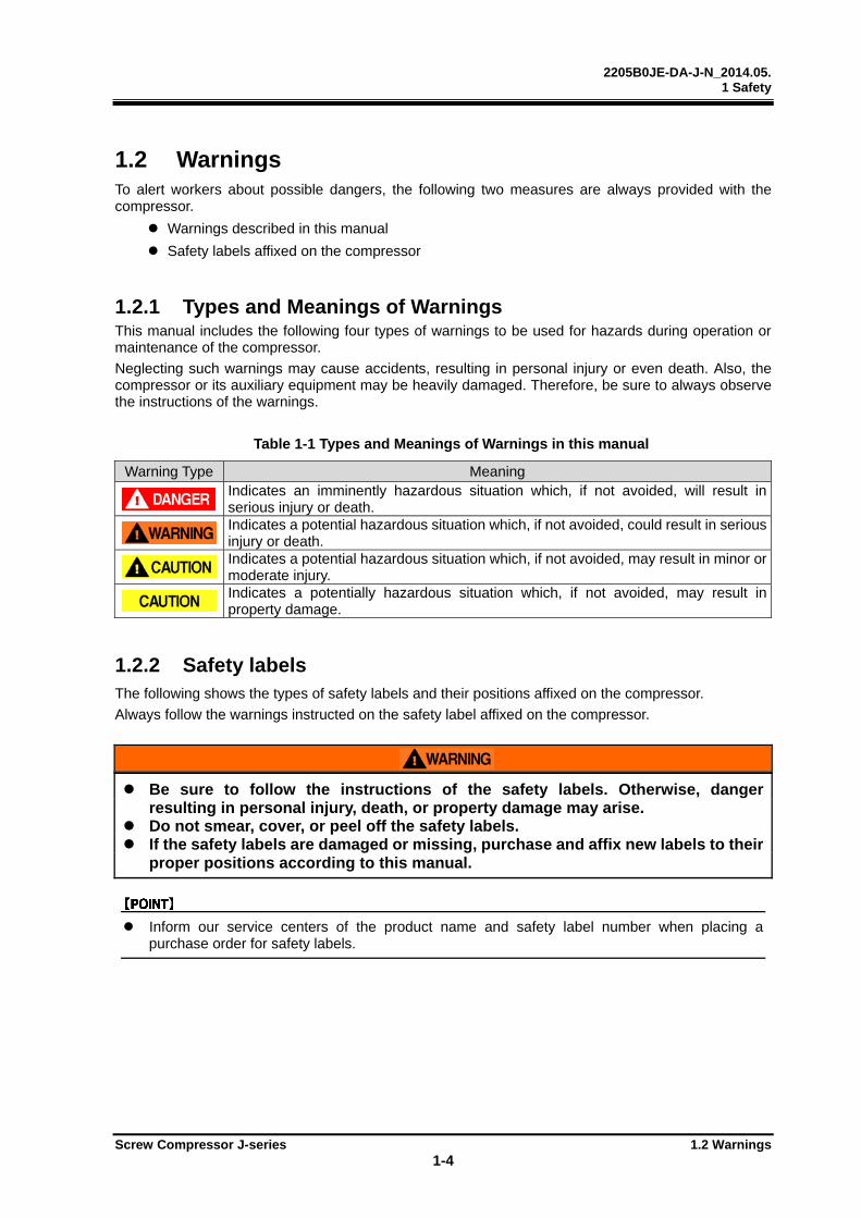
1.2.1 Types and Meanings of Warnings This manual includes the following four types of warnings to be used for hazards during operation or maintenance of the compressor.
Neglecting such warnings may cause accidents, resulting in personal injury or even death. Also, the compressor or its auxiliary equipment may be heavily damaged. Therefore, be sure to always observe the instructions of the warnings.
Table 1-1 Types and Meanings of Warnings in this manual
Warning Type Meaning
Indicates an imminently hazardous situation which, if not avoided, will result in serious injury or death.
Indicates a potential hazardous situation which, if not avoided, could result in serious injury or death.
Indicates a potential hazardous situation which, if not avoided, may result in minor or moderate injury.
Indicates a potentially hazardous situation which, if not avoided, may result in property damage.
1.2.2 Safety labels The following shows the types of safety labels and their positions affixed on the compressor.
Always follow the warnings instructed on the safety label affixed on the compressor.
Be sure to follow the instructions of the safety labels. Otherwise, danger resulting in personal injury, death, or property damage may arise.
Do not smear, cover, or peel off the safety labels. If the safety labels are damaged or missing, purchase and affix new labels to their
proper positions according to this manual.
Inform our service centers of the product name and safety label number when placing a purchase order for safety labels.
2205B0JE-DA-J-N_2014.05. 1 Safety
Screw Compressor J-series 1.2 Warnings
1-5
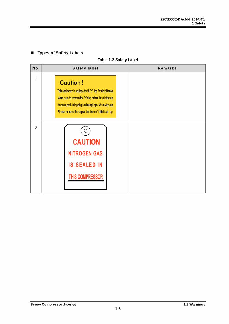
Types of Safety Labels
Table 1-2 Safety Label
No. Safety label Remarks
1
2
2205B0JE-DA-J-N_2014.05. 1 Safety
Screw Compressor J-series 1.2 Warnings
1-6
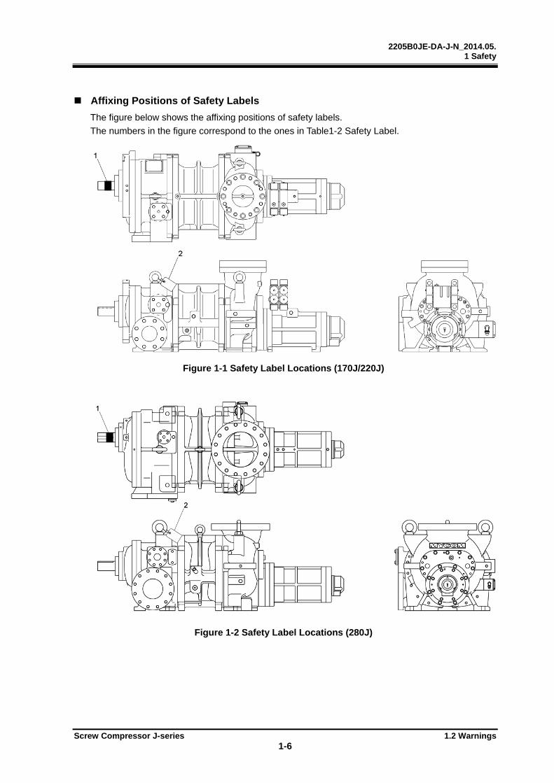
Affixing Positions of Safety Labels
The figure below shows the affixing positions of safety labels.
The numbers in the figure correspond to the ones in Table1-2 Safety Label.
Figure 1-1 Safety Label Locations (170J/220J)
Figure 1-2 Safety Label Locations (280J)
2205B0JE-DA-J-N_2014.05. 1 Safety
Screw Compressor J-series 1.3 Residual Risks
1-7
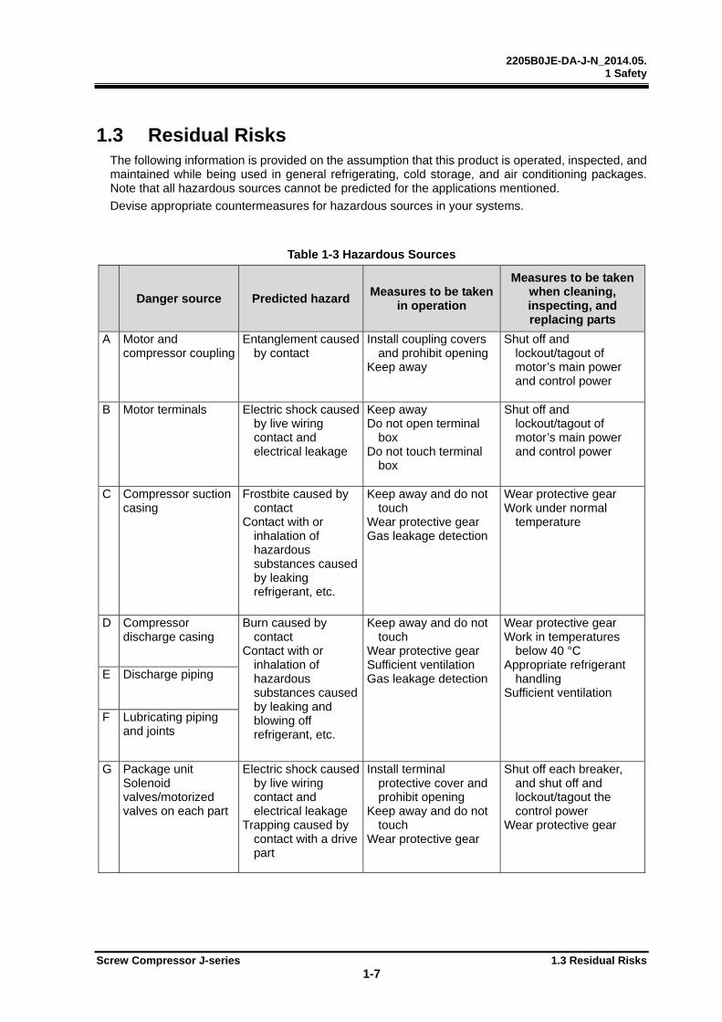
1.3 Residual Risks The following information is provided on the assumption that this product is operated, inspected, and maintained while being used in general refrigerating, cold storage, and air conditioning packages. Note that all hazardous sources cannot be predicted for the applications mentioned.
Devise appropriate countermeasures for hazardous sources in your systems.
Table 1-3 Hazardous Sources
Danger source Predicted hazard Measures to be taken
in operation
Measures to be taken when cleaning, inspecting, and replacing parts
A Motor and compressor coupling
Entanglement caused by contact
Install coupling covers and prohibit opening
Keep away
Shut off and lockout/tagout of motor’s main power and control power
B Motor terminals Electric shock caused
by live wiring contact and electrical leakage
Keep away Do not open terminal
box Do not touch terminal
box
Shut off and lockout/tagout of motor’s main power and control power
C Compressor suction casing
Frostbite caused by contact
Contact with or inhalation of hazardous substances caused by leaking refrigerant, etc.
Keep away and do not touch
Wear protective gear Gas leakage detection
Wear protective gear Work under normal
temperature
D Compressor discharge casing
Burn caused by contact
Contact with or inhalation of hazardous substances caused by leaking and blowing off refrigerant, etc.
Keep away and do not touch
Wear protective gear Sufficient ventilation Gas leakage detection
Wear protective gear Work in temperatures
below 40 °C Appropriate refrigerant
handling Sufficient ventilation
E Discharge piping
F Lubricating piping and joints
G Package unit Solenoid valves/motorized valves on each part
Electric shock caused by live wiring contact and electrical leakage
Trapping caused by contact with a drive part
Install terminal protective cover and prohibit opening
Keep away and do not touch
Wear protective gear
Shut off each breaker, and shut off and lockout/tagout the control power
Wear protective gear

2205B0JE-DA-J-N_2014.05. 1 Safety
Screw Compressor J-series 1.3 Residual Risks
1-8
Danger source Predicted hazard Measures to be taken
in operation
Measures to be taken when cleaning, inspecting, and replacing parts
H Package unit Electric components of each part (oil heater, protective switch, etc.)
Electric shock caused by live wiring contact and electrical leakage
Burn caused by contact
Install terminal protective cover and prohibit opening
Keep away and do not touch
Wear protective gear
Shut off each breaker, and shut off and lockout/tagout the control power
Wear protective gear
I
Package unit Oil drains
Contact with hazard-ous substances caused by leakage and blowoff
Burn caused by contacting with high temperature fluid
Sufficient ventilation Keep away and do not
touch Wear protective gear
Sufficient ventilation Wear protective gear Work in temperatures
below 40 °C
J Noises Hearing disabilities caused by noises
Wear protective gear
—
2205B0JE-DA-J-N_2014.05. 1 Safety
Screw Compressor J-series 1.3 Residual Risks
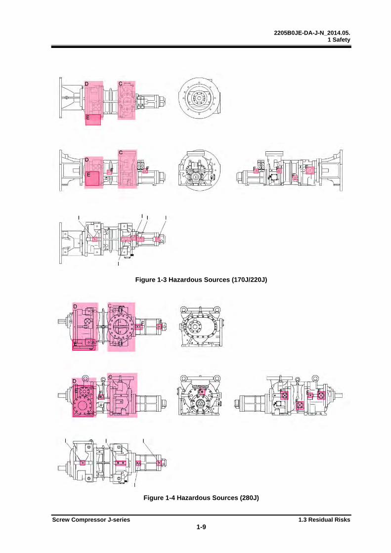
1-9
Figure 1-3 Hazardous Sources (170J/220J)
Figure 1-4 Hazardous Sources (280J)
2205B0JE-DA-J-N_2014.05. 1 Safety
Screw Compressor J-series 1.4 Safety Devices
1-10
1.4 Safety Devices For safe use and protection of the compressor, make sure to attach safety devices to the compressor that comply with the regulations and the following descriptions.
Safety devices must be properly and periodically maintained and inspected. It is important to include maintenance and inspection of safety devices in the periodical maintenance/inspection schedule. Make sure to provide users of the compressor with necessary information on types, attachment positions, functions, inspection method of the safety devices.
Check the safety devices after turning on the power and before operation of the compressor. If they do not operate normally, immediately take measures to replace them.
1.4.1 Emergency Stop Button
Overview/Function/Purpose The emergency stop buttons are used to stop the compressor operation immediately if an emergency occurs to the compressor.
Installation Locations The emergency stop buttons should be installed in the controller on the compressor and in the operating control room
Stop/Reset Methods To activate and reset the emergency stop buttons, refer to the unit instruction manual.
Inspection Method/Cycle The emergency stop buttons must be tested before a test run as well as periodically. For details about the inspection procedure and inspection cycle of the emergency stop buttons, refer to the unit instruction manual.
1.4.2 Breakers for the Main Motor Power and Control Power (with Lockout/Tagout Devices)
Overview/Function/Purpose Turn off the main motor and control power, and if there are any possibilities of danger during work (especially during cleaning, maintenance, inspection, or troubleshooting), lockout/tagout devices must be set up for breakers of the main motor and control powers to prevent injury to workers in case the power is turned on accidentally during work.
Methods of Performing and Releasing Lockout/Tagout In accordance with the regulations created by Occupational Safety & Health Administration (OSHA) and other authorities, make sure to clearly indicate methods of performing and releasing lockout/tagout and provide users of this compressor with the necessary information.
Inspection Method/Cycle For inspection procedures and the inspection cycle of the lockout/tagout devices, refer to the unit instruction manual.

2205B0JE-DA-J-N_2014.05. 1 Safety
Screw Compressor J-series 1.4 Safety Devices
1-11
1.4.3 Compressor Protection Devices
Overview/Function/Purpose To protect the compressor, the following safety functions of the CP4 controller are used.
Protection from High discharge temperature This function stops the compressor when the discharge temperature exceeds the set value.
A temperature sensor is installed in the oil separator.
Protection from High oil temperature This function stops the compressor when the oil temperature exceeds the set value.
A temperature sensor is installed in the package lubrication piping after the oil cooler.
Protection from abnormally High pressure This function stops the compressor when the discharge pressure abnormally rises due to compressor misoperations or stoppage of cooling water supply to the condenser.
This function prevents explosion of the equipment and components.
A pressure sensor is installed in the oil separator.
Protection from abnormally Low suction pressure This function stops the compressor when the suction pressure is below the set value.
A pressure sensor is installed in the suction piping.
Protection from abnormal oil pressure This function stops the compressor when oil supply is not sufficient, the oil filter is clogged, too much refrigerant in oil, or oil supply pressure difference (from suction pressure) is below the set value. This is to protect the compressor from wear and seizure.
A pressure sensor is installed after the oil filter.
Protection from oil filter Differential pressure This function stops the compressor when the differential pressure between discharge and lubrication pressure is below the set value due to clogging of filters or other reasons.
The discharge and the oil pressure sensors are used.
Protection from Low oil level [Case 1 Differential pressure oil supply system]
This function constantly detects the oil level in the oil separator and stops the compressor when the oil level is below the lower limit.
Oil level sensor is installed in the oil separator.
[Case 2 Forced oil supply system]
When the oil level gets lower and the oil pump takes in the refrigerant gas, the differential pressure between before and after the oil pump decreases. When the differential pressure between before and after the oil pump is less than the specified value, the system will stop the compressor operation.
Protection from motor over-current This function controls the unloader of compressor when current exceeds the set value (upper limit). In some cases, it stops the compressor.
The current value is monitored by the CP4 controller.
2205B0JE-DA-J-N_2014.05. 1 Safety
Screw Compressor J-series 1.4 Safety Devices
1-12
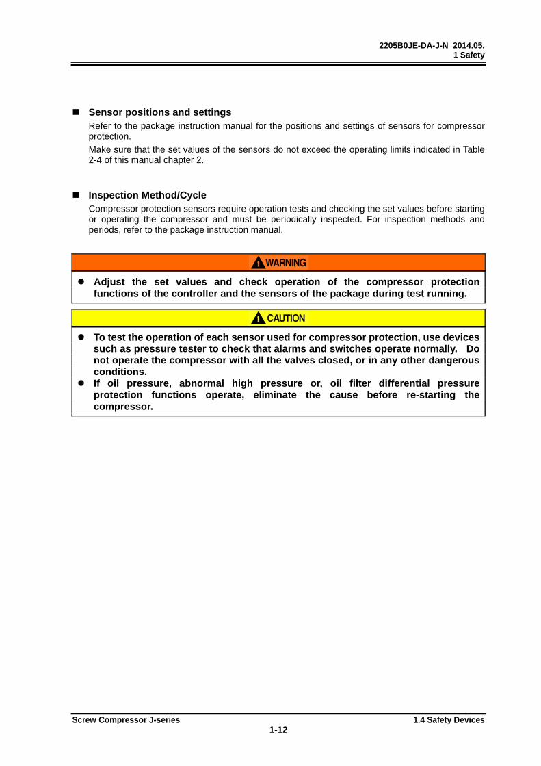
Sensor positions and settings Refer to the package instruction manual for the positions and settings of sensors for compressor protection.
Make sure that the set values of the sensors do not exceed the operating limits indicated in Table 2-4 of this manual chapter 2.
Inspection Method/Cycle Compressor protection sensors require operation tests and checking the set values before starting or operating the compressor and must be periodically inspected. For inspection methods and periods, refer to the package instruction manual.
Adjust the set values and check operation of the compressor protection functions of the controller and the sensors of the package during test running.
To test the operation of each sensor used for compressor protection, use devices such as pressure tester to check that alarms and switches operate normally. Do not operate the compressor with all the valves closed, or in any other dangerous conditions.
If oil pressure, abnormal high pressure or, oil filter differential pressure protection functions operate, eliminate the cause before re-starting the compressor.
2205B0JE-DA-J-N_2014.05. 2 Structure and Specifications of the Compressor
Screw Compressor J-series 2.1 Features of the J-Series Screw Compressor 2-1
2 Structure and Specifications of the Compressor
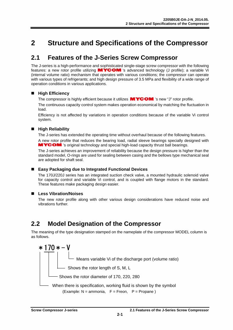
2.1 Features of the J-Series Screw Compressor The J-series is a high-performance and sophisticated single-stage screw compressor with the following features: a new rotor profile utilizing ’s advanced technology (J profile); a variable Vi (internal volume ratio) mechanism that operates with various conditions; the compressor can operate with various types of refrigerants; and high design pressure of 3.5 MPa and flexibility of a wide range of operation conditions in various applications.
High Efficiency The compressor is highly efficient because it utilizes ’s new “J” rotor profile.
The continuous capacity control system makes operation economical by matching the fluctuation in load.
Efficiency is not affected by variations in operation conditions because of the variable Vi control system.
High Reliability The J-series has extended the operating time without overhaul because of the following features.
A new rotor profile that reduces the bearing load, radial sleeve bearings specially designed with ’s original technology and special high-load capacity thrust ball bearings.
The J-series achieves an improvement of reliability because the design pressure is higher than the standard model, O-rings are used for sealing between casing and the bellows type mechanical seal are adopted for shaft seal.
Easy Packaging due to Integrated Functional Devices The 170J/220J series has an integrated suction check valve, a mounted hydraulic solenoid valve for capacity control and variable Vi control, and is coupled with flange motors in the standard. These features make packaging design easier.
Less Vibration/Noises The new rotor profile along with other various design considerations have reduced noise and vibrations further.
2.2 Model Designation of the Compressor The meaning of the type designation stamped on the nameplate of the compressor MODEL column is as follows.
* 170 * - V
Means variable Vi of the discharge port (volume ratio)
Shows the rotor length of S, M, L
Shows the rotor diameter of 170, 220, 280
When there is specification, working fluid is shown by the symbol (Example: N = ammonia, F = Freon, P = Propane )
2205B0JE-DA-J-N_2014.05. 2 Structure and Specifications of the Compressor
Screw Compressor J-series 2.3 Compressor Specifications 2-2
2.3 Compressor Specifications
2.3.1 Specifications
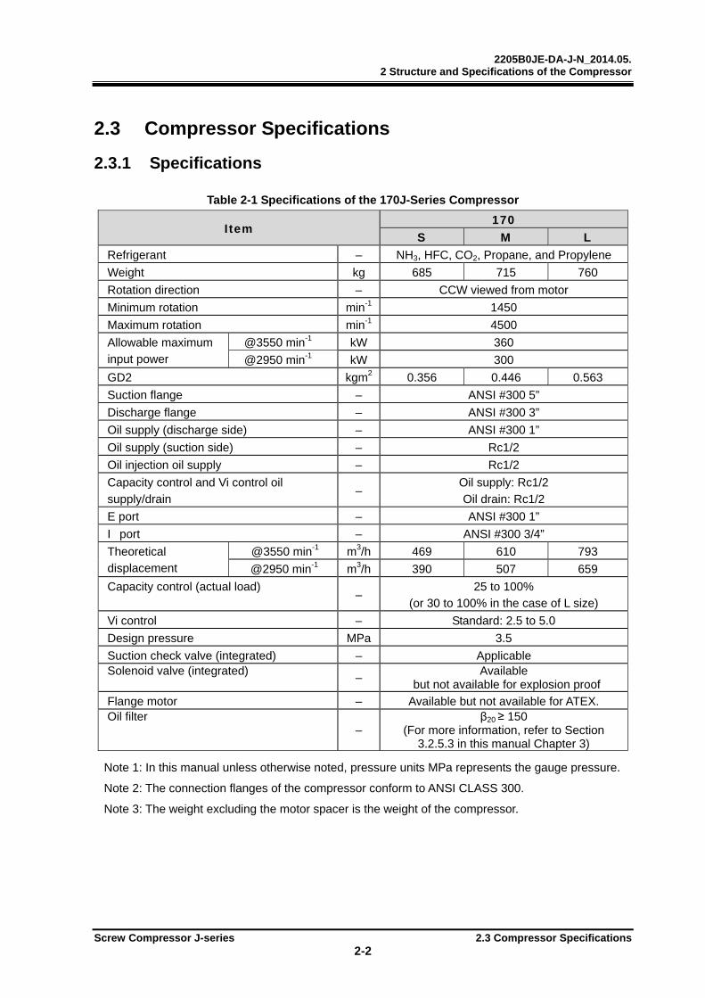
Table 2-1 Specifications of the 170J-Series Compressor
I tem 170
S M L
Refrigerant – NH3, HFC, CO2, Propane, and Propylene
Weight kg 685 715 760
Rotation direction – CCW viewed from motor
Minimum rotation min-1 1450
Maximum rotation min-1 4500
Allowable maximum input power
@3550 min-1 kW 360
@2950 min-1 kW 300
GD2 kgm2 0.356 0.446 0.563
Suction flange – ANSI #300 5”
Discharge flange – ANSI #300 3”
Oil supply (discharge side) – ANSI #300 1”
Oil supply (suction side) – Rc1/2
Oil injection oil supply – Rc1/2
Capacity control and Vi control oil
supply/drain –
Oil supply: Rc1/2
Oil drain: Rc1/2
E port – ANSI #300 1”
I port – ANSI #300 3/4”
Theoretical displacement
@3550 min-1 m3/h 469 610 793
@2950 min-1 m3/h 390 507 659
Capacity control (actual load) –
25 to 100% (or 30 to 100% in the case of L size)
Vi control – Standard: 2.5 to 5.0
Design pressure MPa 3.5
Suction check valve (integrated) – Applicable Solenoid valve (integrated)
– Available
but not available for explosion proof
Flange motor – Available but not available for ATEX. Oil filter
– β20 ≥ 150
(For more information, refer to Section 3.2.5.3 in this manual Chapter 3)
Note 1: In this manual unless otherwise noted, pressure units MPa represents the gauge pressure.
Note 2: The connection flanges of the compressor conform to ANSI CLASS 300.
Note 3: The weight excluding the motor spacer is the weight of the compressor.

2205B0JE-DA-J-N_2014.05. 2 Structure and Specifications of the Compressor
Screw Compressor J-series 2.3 Compressor Specifications 2-3
Table 2-2 Specifications of the 220J-Series Compressor
I tem 220
S M L
Refrigerant – NH3, HFC, CO2, Propane, and Propylene
Weight kg 1255 1315 1385
Rotation direction – CCW viewed from motor
Minimum rotation min-1 1450
Maximum rotation min-1 4500
Allowable maximum input power
@3550 min-1 kW 750
@2950 min-1 kW 625
GD2 kgm2 1.312 1.648 2.082
Suction flange – ANSI #300 8”
Discharge flange – ANSI #300 5”
Oil supply (discharge side) – ANSI #300 1”
Oil supply (suction side) – Rc3/4
Oil injection oil supply – Rc3/4
Capacity control and Vi control oil supply/drain
– Oil supply: Rc1/2 Oil drain: Rc1/2
E port – ANSI #300 1 1/2”
I port – ANSI #300 3/4”
Theoretical displacement
@3550 min-1 m3/h 1030 1340 1741
@2950 min-1 m3/h 856 1114 1447 Capacity control (actual load)
– 25 to 100%
(or 30 to 100% in the case of L size)
Vi control – Standard: 2.5 to 5.0
Design pressure MPa 3.5
Suction check valve (integrated) – Applicable Solenoid valve (integrated)
– Available
but not available for explosion proof
Flange motor – Available but not available for ATEX. Oil filter
– β20 ≥ 150
(For more information, refer to Section 3.2.5.3 in this manual Chapter 3)
Note 1: In this manual unless otherwise noted, pressure units MPa represents the gauge pressure.
Note 2: The connection flanges of the compressor conform to ANSI CLASS 300.
Note 3: The weight excluding the motor spacer is the weight of the compressor.

2205B0JE-DA-J-N_2014.05. 2 Structure and Specifications of the Compressor
Screw Compressor J-series 2.3 Compressor Specifications 2-4
Table 2-3 Specifications of the 280J-Series Compressor
I tem 280
S M L
Refrigerant – NH3, HFC, CO2, Propane, and Propylene
Weight kg 2285 2435 2585
Rotation direction – CCW viewed from motor
Minimum rotation min-1 1450
Maximum rotation min-1 3600
Allowable maximum @3550 min-1 kW 1650
input power @2950 min-1 kW 1375
GD2 kgm2 4.887 6.134 7.765
Suction flange – ANSI #300 12”
Discharge flange – ANSI #300 8”
Oil supply (discharge side) – ANSI #300 1”
Oil supply (suction side) – ANSI #300 3/4”
Oil injection oil supply – ANSI #300 1 1/4” Capacity control and Vi control oil supply/drain
–
Capacity control Increase/Decrease : Rc1/2 on each side
Vi control Increase/Decrease : Rc1/2 on each side
E port – ANSI #300 2 1/2”
I port – ANSI #300 1”
Theoretical
displacement
@3550 min-1 m3/h 2269 2949 3839
@2950 min-1 m3/h 1886 2451 3190 Capacity control (actual load)
– 25 to 100%
(or 30 to 100% in the case of L size)
Vi control – Standard: 2.5 to 5.0
Design pressure MPa 3.5
Suction check valve (integrated) – N/A
Solenoid valve (integrated) – N/A
Flange motor – Non-Available Oil filter
– β20 ≥ 150
(For more information, refer to Section 3.2.5.3 in this manual Chapter 3)
Note 1: In this manual unless otherwise noted, pressure units MPa represents the gauge pressure.
Note 2: The connection flanges of the compressor conform to ANSI CLASS 300.
2205B0JE-DA-J-N_2014.05. 2 Structure and Specifications of the Compressor
Screw Compressor J-series 2.3 Compressor Specifications 2-5
2.3.2 Operation Limits
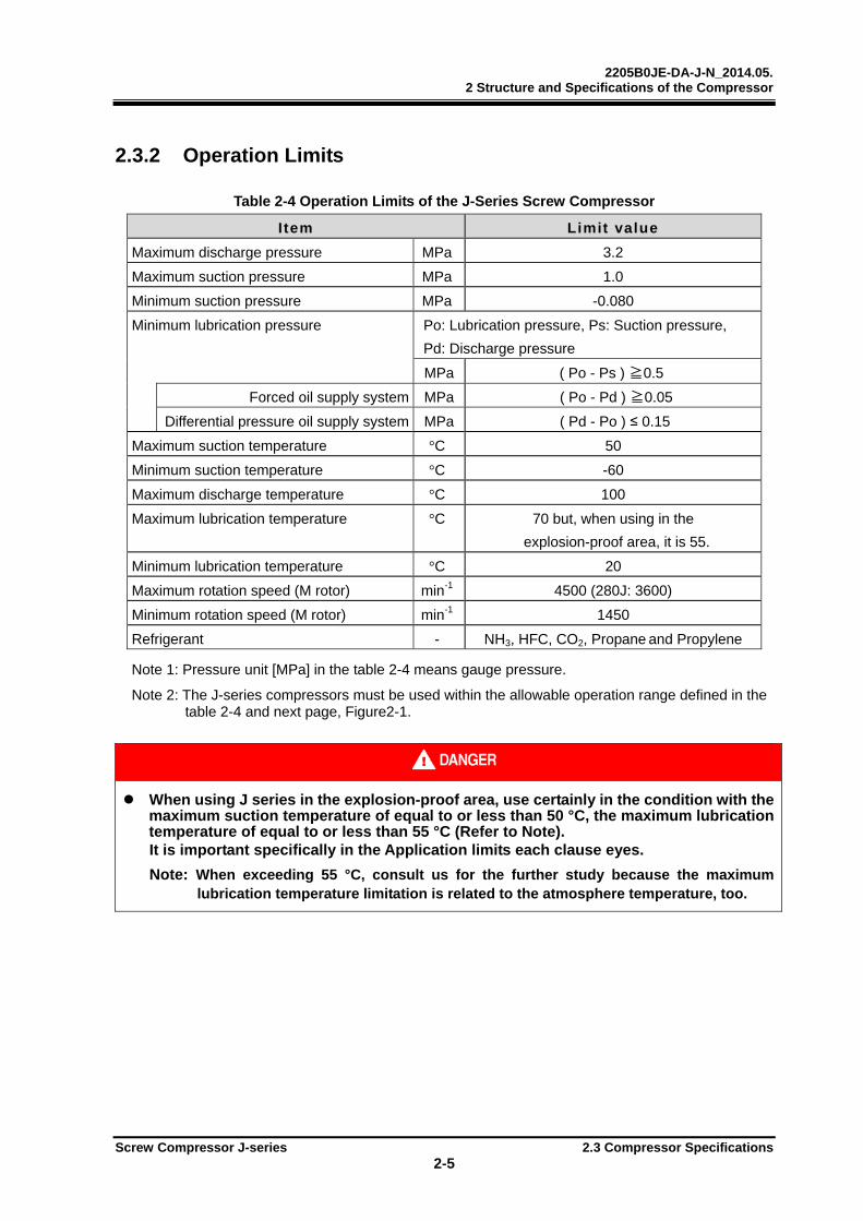
Table 2-4 Operation Limits of the J-Series Screw Compressor
I tem Limit value
Maximum discharge pressure MPa 3.2
Maximum suction pressure MPa 1.0
Minimum suction pressure MPa -0.080
Minimum lubrication pressure Po: Lubrication pressure, Ps: Suction pressure,
Pd: Discharge pressure
MPa ( Po - Ps ) ≧0.5
Forced oil supply system MPa ( Po - Pd ) ≧0.05
Differential pressure oil supply system MPa ( Pd - Po ) ≤ 0.15
Maximum suction temperature °C 50
Minimum suction temperature °C -60
Maximum discharge temperature °C 100
Maximum lubrication temperature °C 70 but, when using in the
explosion-proof area, it is 55.
Minimum lubrication temperature °C 20
Maximum rotation speed (M rotor) min-1 4500 (280J: 3600)
Minimum rotation speed (M rotor) min-1 1450
Refrigerant - NH3, HFC, CO2, Propane and Propylene Note 1: Pressure unit [MPa] in the table 2-4 means gauge pressure.
Note 2: The J-series compressors must be used within the allowable operation range defined in the table 2-4 and next page, Figure2-1.
When using J series in the explosion-proof area, use certainly in the condition with the maximum suction temperature of equal to or less than 50 °C, the maximum lubrication temperature of equal to or less than 55 °C (Refer to Note).
It is important specifically in the Application limits each clause eyes. Note: When exceeding 55 °C, consult us for the further study because the maximum
lubrication temperature limitation is related to the atmosphere temperature, too.
2205B0JE-DA-J-N_2014.05. 2 Structure and Specifications of the Compressor
Screw Compressor J-series 2.3 Compressor Specifications 2-6
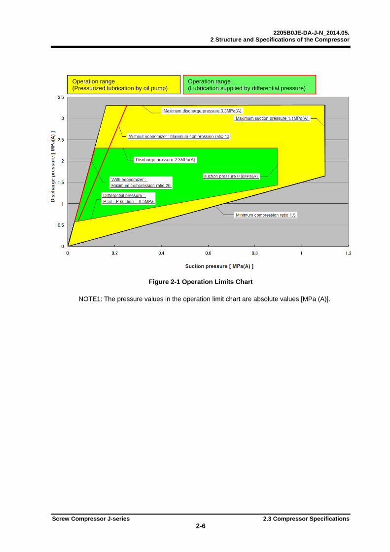
Figure 2-1 Operation Limits Chart
NOTE1: The pressure values in the operation limit chart are absolute values [MPa (A)].
Operation range (Pressurized lubrication by oil pump)
Operation range (Lubrication supplied by differential pressure)
2205B0JE-DA-J-N_2014.05. 2 Structure and Specifications of the Compressor
Screw Compressor J-series 2.3 Compressor Specifications 2-7
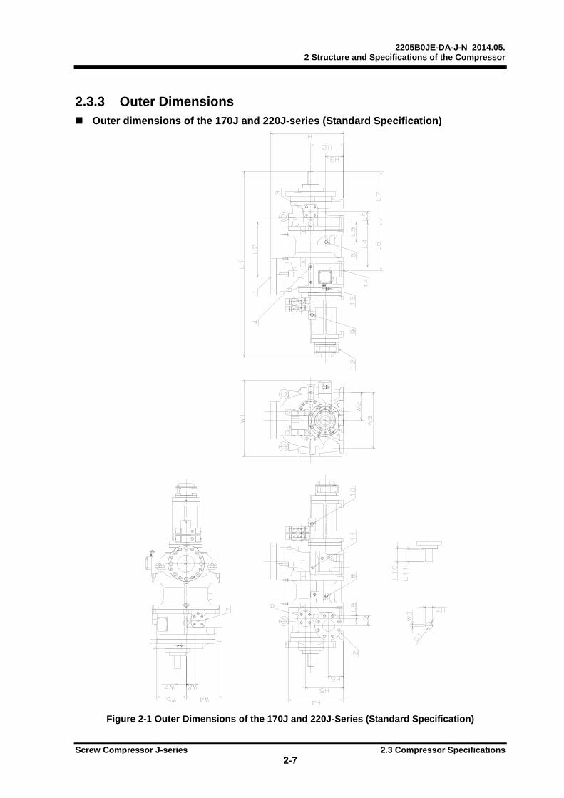
2.3.3 Outer Dimensions Outer dimensions of the 170J and 220J-series (Standard Specification)
Figure 2-1 Outer Dimensions of the 170J and 220J-Series (Standard Specification)
2205B0JE-DA-J-N_2014.05. 2 Structure and Specifications of the Compressor
Screw Compressor J-series 2.3 Compressor Specifications 2-8
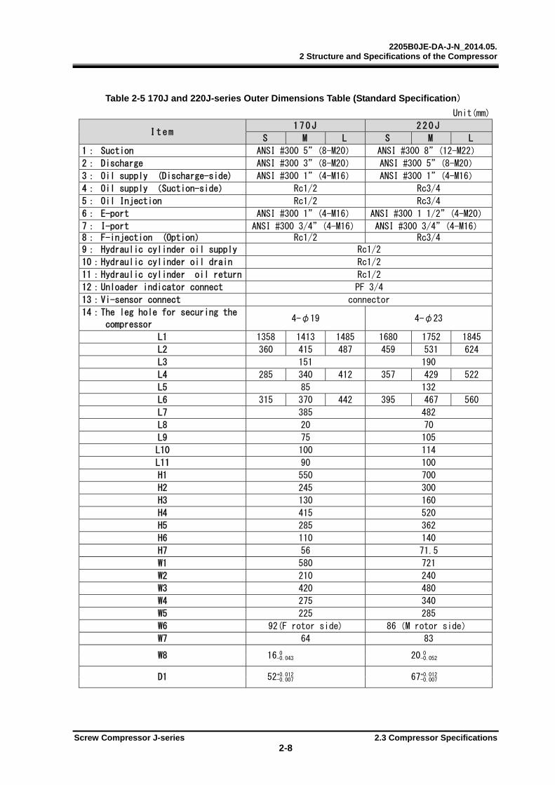
Table 2-5 170J and 220J-series Outer Dimensions Table (Standard Specification)
Unit(mm)
I t e m 1 7 0 J 2 2 0 J
S M L S M L
1: Suction ANSI #300 5”(8-M20) ANSI #300 8”(12-M22)
2: Discharge ANSI #300 3”(8-M20) ANSI #300 5”(8-M20)
3: Oil supply (Discharge-side) ANSI #300 1”(4-M16) ANSI #300 1”(4-M16)
4: Oil supply (Suction-side) Rc1/2 Rc3/4
5: Oil Injection Rc1/2 Rc3/4
6: E-port ANSI #300 1”(4-M16) ANSI #300 1 1/2”(4-M20)
7: I-port ANSI #300 3/4”(4-M16) ANSI #300 3/4”(4-M16) 8: F-injection (Option) Rc1/2 Rc3/4
9: Hydraulic cylinder oil supply Rc1/2
10:Hydraulic cylinder oil drain Rc1/2
11:Hydraulic cylinder oil return Rc1/2
12:Unloader indicator connect PF 3/4
13:Vi-sensor connect connector
14:The leg hole for securing the
compressor 4-φ19 4-φ23
L1 1358 1413 1485 1680 1752 1845
L2 360 415 487 459 531 624
L3 151 190
L4 285 340 412 357 429 522
L5 85 132
L6 315 370 442 395 467 560
L7 385 482
L8 20 70
L9 75 105
L10 100 114
L11 90 100
H1 550 700
H2 245 300
H3 130 160
H4 415 520
H5 285 362
H6 110 140
H7 56 71.5
W1 580 721
W2 210 240
W3 420 480
W4 275 340
W5 225 285
W6 92(F rotor side) 86(M rotor side)
W7 64 83
W8 16 0 20 0 -0.043 -0.052
D1 52+0.012 67+0.012 -0.007 -0.007

2205B0JE-DA-J-N_2014.05. 2 Structure and Specifications of the Compressor
Screw Compressor J-series 2.3 Compressor Specifications 2-9
Outer dimensions of the 170J and 220J-series (Motor Spacer)
Figure 2-3 Outer Dimensions of the 170J and 220J-Series (Motor Spacer)
Table 2-6 170J and 220J-series Outer Dimensions Table (Motor Spacer) Unit: mm
I t e m
1 7 0 J 2 2 0 J
NEMA IEC NEMA IEC
44*D 50*D FF-500 FF-600 44*D 50*D FF-600 FF-740
15 8-M20 8-M16 8-M20 8-M20
16 2-φ19 2-φ23
L12 126 140
L13 221 241 250
H7 245 300
W9 292 314
D2 457.2 450 550 457.2 550 680
D3 508 558.8 500 600 508 558.8 600 740
D4 660 558 810
2205B0JE-DA-J-N_2014.05. 2 Structure and Specifications of the Compressor
Screw Compressor J-series 2.3 Compressor Specifications 2-10
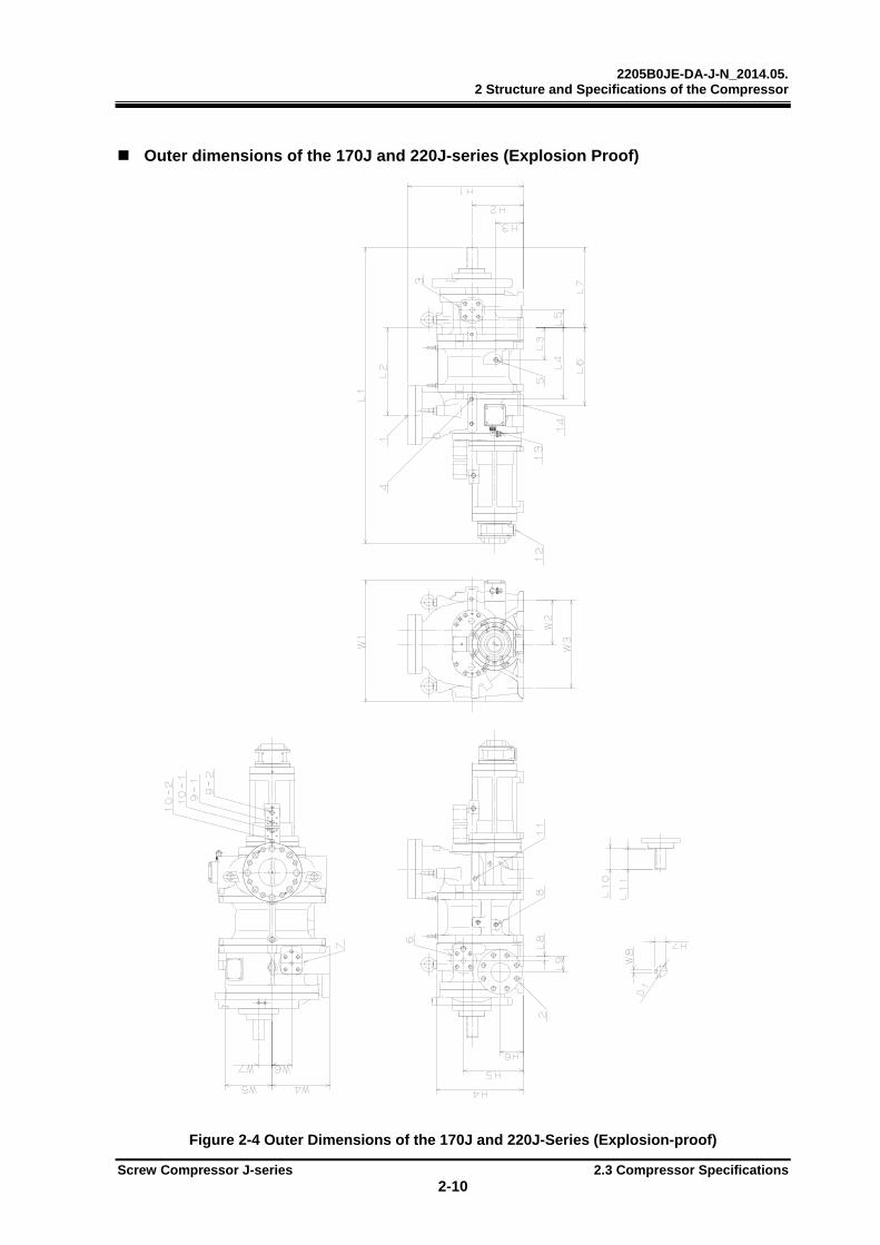
Outer dimensions of the 170J and 220J-series (Explosion Proof)
Figure 2-4 Outer Dimensions of the 170J and 220J-Series (Explosion-proof)

2205B0JE-DA-J-N_2014.05. 2 Structure and Specifications of the Compressor
Screw Compressor J-series 2.3 Compressor Specifications 2-11
Table 2-7 Outer Dimensions of the 170J and 220J-Series (Explosion-proof)
Unit: mm
項 目 170J 2 2 0 J
S M L S M L
1:Suction ANSI #300 5”(8-M20) ANSI #300 8”(12-M22)
2:Discharge ANSI #300 3”(8-M20) ANSI #300 5”(8-M20)
3:Oil supply (Discharge- side) ANSI #300 1”(4-M16) ANSI #300 1”(4-M16)
4:Oil supply (Suction-side) Rc1/2 Rc3/4
5:Oil injection Rc1/2 Rc3/4
6:E-port ANSI #300 1”(4-M16) ANSI #300 1 1/2”(4-M20)
7:I-port ANSI #300 3/4”(4-M16) ANSI #300 3/4”(4-M16)8:F-injection (Option) Rc1/2 Rc3/4
9-1:Capacity control increase Rc1/2
9-2:Capacity control decrease Rc1/2
10-1:Vi control increase(L→H) Rc1/2
10-2:Vi control decrease(H→L) Rc1/2
11:Capacity control oil return Rc1/2
12:Unloader indicator connect PF 3/4
13:Vi-sensor connect connector
14:The leg hole for securing the compressor
4-φ19 4-φ23
L1 1358 1413 1485 1680 1752 1845
L2 360 415 487 459 531 624
L3 151 190
L4 285 340 412 357 429 522
L5 85 132
L6 315 370 442 395 467 560
L7 385 482
L8 20 70
L9 75 105
L10 100 114
L11 90 100
H1 550 700
H2 245 300
H3 130 160
H4 415 520
H5 285 362
H6 110 140
H7 56 71.5
W1 580 721
W2 210 240
W3 420 480
W4 275 340
W5 225 285
W6 92(F rotor side) 86(M rotor side)
W7 64 83
W8 16 0 20 0 -0.043 -0.052
D1 52+0.012 67+0.012 -0.007 -0.007
2205B0JE-DA-J-N_2014.05. 2 Structure and Specifications of the Compressor
Screw Compressor J-series 2.3 Compressor Specifications 2-12
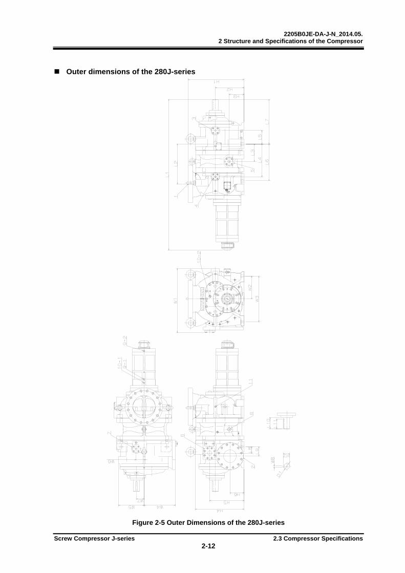
Outer dimensions of the 280J-series
Figure 2-5 Outer Dimensions of the 280J-series

2205B0JE-DA-J-N_2014.05. 2 Structure and Specifications of the Compressor
Screw Compressor J-series 2.3 Compressor Specifications 2-13
Table 2-8 Outer Dimensions of the 280J-series Unit: mm
I t e m 2 8 0 J
S M L
1:Suction ANSI #300 12”(16-M30)
2:Discharge ANSI #300 8”(12-M22)
3:Oil supply (Discharge-side) ANSI #300 1”(4-M16)
4:Oil supply (Suction-side) ANSI #300 3/4”(4-M16)
5:Oil injection ANSI #300 1 1/4”(4-M16)
6:E-port ANSI #300 2 1/2”(8-M20)
7:I-port ANSI #300 1”(4-M16) 8:F-injection (Option) Rc1 1/4
9-1:Capacity control increase Rc1/2
9-2:Capacity control decrease Rc1/2
10-1:Vi control increase(L→H) Rc1/2
10-2:Vi control decrease(H→L) Rc1/2
11:Capacity control oil return Rc1/2
12:Unloader indicator connect PF 3/4
13:Vi-sensor connect connector
14:The leg hole for securing the compressor
4-φ33
L1 2112 2205 2328
L2 562 655 778
L3 247
L4 460 553 676
L5 186
L6 517 610 733
L7 624
L8 90
L9 130
L10 158
L11 140
H1 780
H2 400
H3 205
H4 680
H5 481
H6 195
H7 90
W1 896
W2 320
W3 640
W4 440
W5 355
W6 112(M rotor side)
W7 108
W8 25 0-0.052
D1 85+0.011-0.011
2205B0JE-DA-J-N_2014.05. 2 Structure and Specifications of the Compressor
Screw Compressor J-series 2.4 Structure of the Compressor 2-14
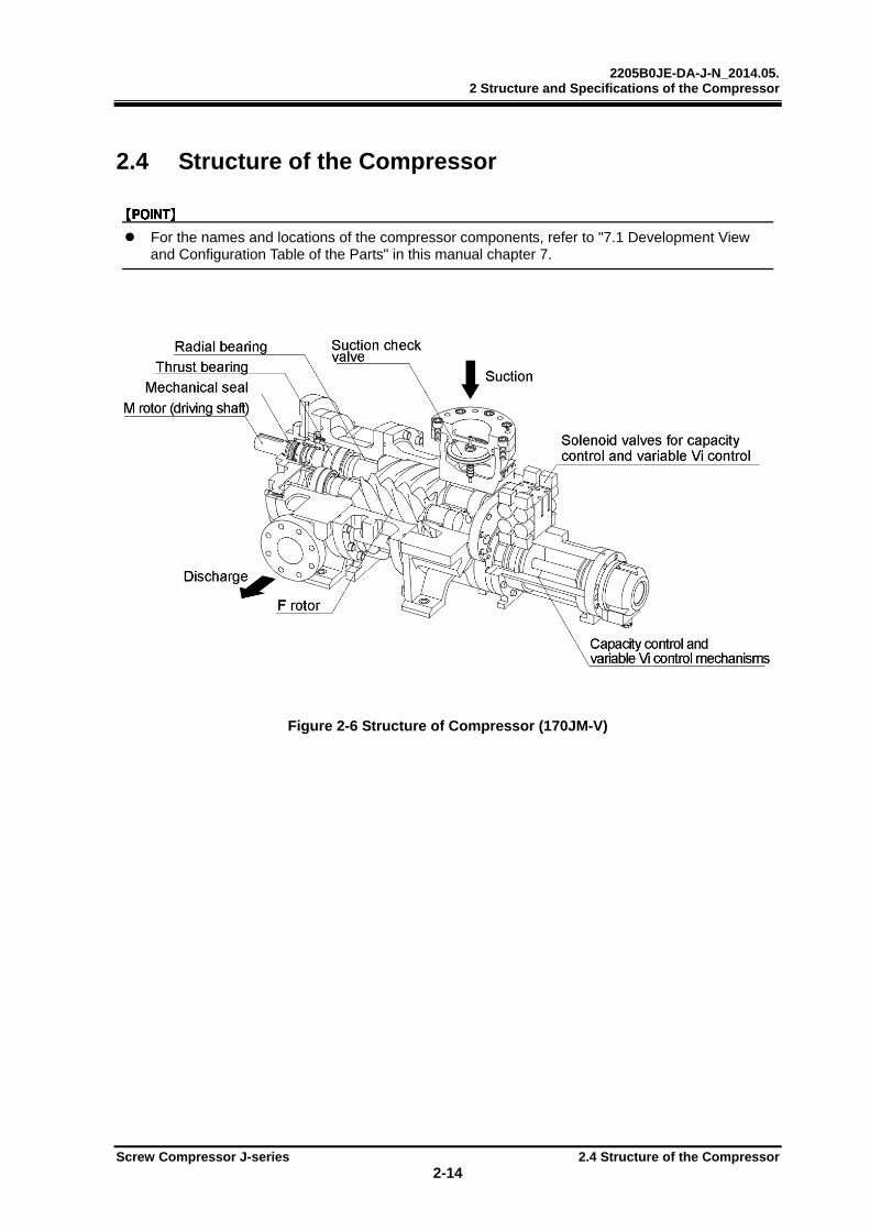
2.4 Structure of the Compressor
For the names and locations of the compressor components, refer to "7.1 Development View and Configuration Table of the Parts" in this manual chapter 7.
Figure 2-6 Structure of Compressor (170JM-V)
2205B0JE-DA-J-N_2014.05. 2 Structure and Specifications of the Compressor
Screw Compressor J-series 2.4 Structure of the Compressor 2-15
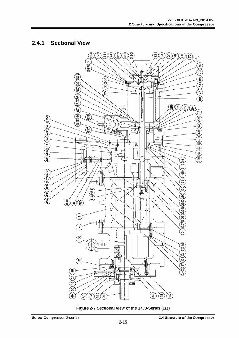
2.4.1 Sectional View
Figure 2-7 Sectional View of the 170J-Series (1/3)
2205B0JE-DA-J-N_2014.05. 2 Structure and Specifications of the Compressor
Screw Compressor J-series 2.4 Structure of the Compressor 2-16
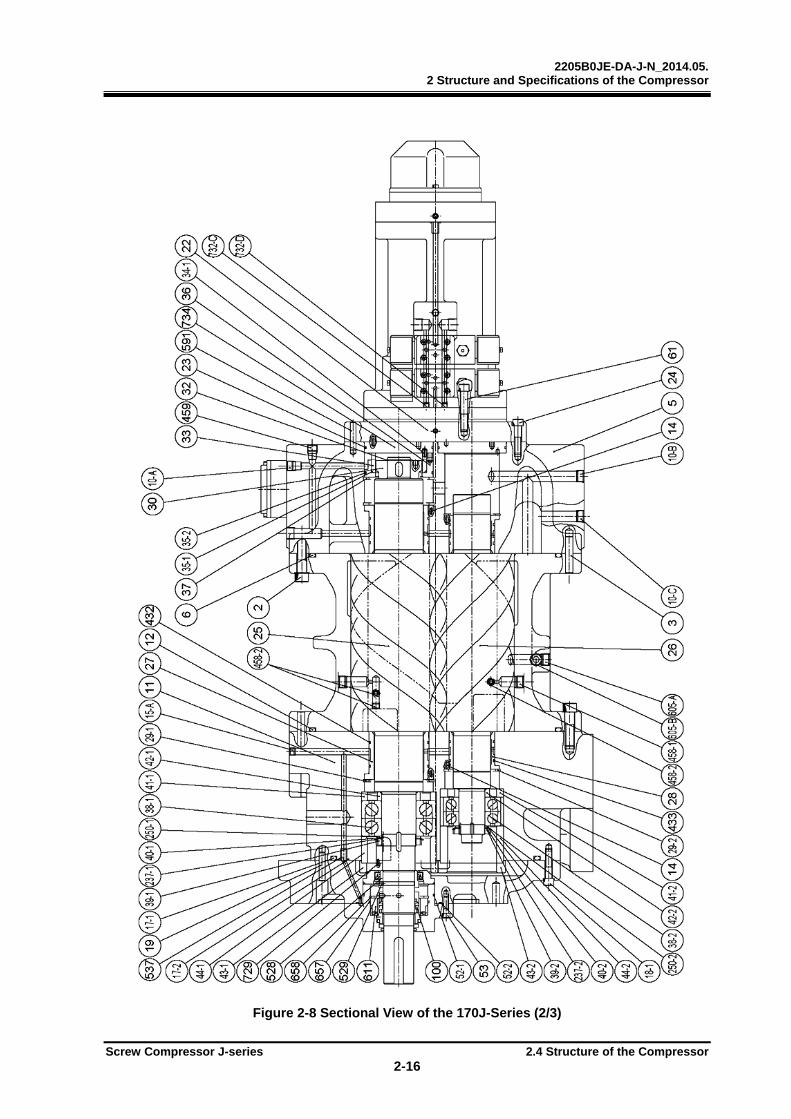
Figure 2-8 Sectional View of the 170J-Series (2/3)

2205B0JE-DA-J-N_2014.05. 2 Structure and Specifications of the Compressor
Screw Compressor J-series 2.4 Structure of the Compressor 2-17
794 ASSY
Figure 2-9 Sectional View of the 170J-Series (3/3)
[ Liquid Injection Port ] [ Economizer Port ]
2205B0JE-DA-J-N_2014.05. 2 Structure and Specifications of the Compressor
Screw Compressor J-series 2.4 Structure of the Compressor 2-18
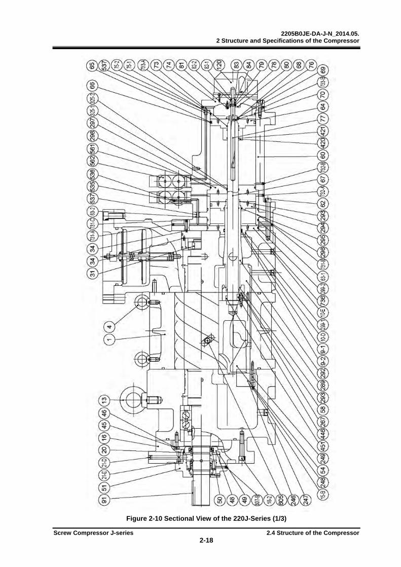
Figure 2-10 Sectional View of the 220J-Series (1/3)
2205B0JE-DA-J-N_2014.05. 2 Structure and Specifications of the Compressor
Screw Compressor J-series 2.4 Structure of the Compressor 2-19
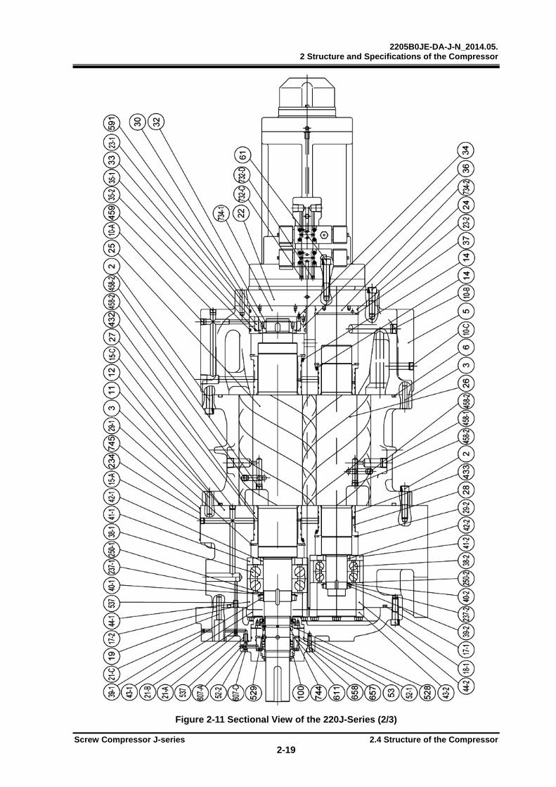
Figure 2-11 Sectional View of the 220J-Series (2/3)

2205B0JE-DA-J-N_2014.05. 2 Structure and Specifications of the Compressor
Screw Compressor J-series 2.4 Structure of the Compressor 2-20
794 ASSY
Figure 2-12 Sectional View of the 220J-Series (3/3)
[ Liquid Injection Port ] [ Economizer Port ]
2205B0JE-DA-J-N_2014.05. 2 Structure and Specifications of the Compressor
Screw Compressor J-series 2.4 Structure of the Compressor 2-21
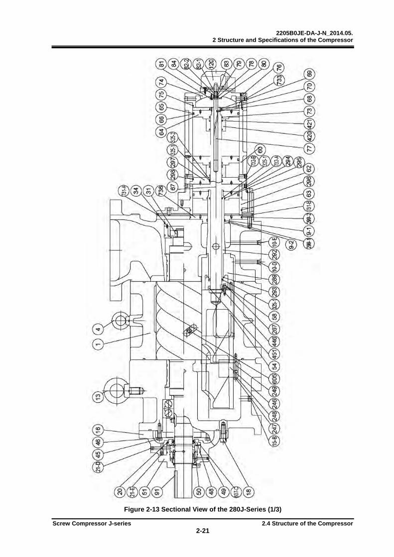
Figure 2-13 Sectional View of the 280J-Series (1/3)

2205B0JE-DA-J-N_2014.05. 2 Structure and Specifications of the Compressor
Screw Compressor J-series 2.4 Structure of the Compressor 2-22
Figure 2-14 Sectional View of the 280J-Series (2/3)

2205B0JE-DA-J-N_2014.05. 2 Structure and Specifications of the Compressor
Screw Compressor J-series 2.4 Structure of the Compressor 2-23
794 ASSY
Figure 2-15 Sectional View of the 280J-Series (3/3)
[ Liquid Injection Port ] [ Economizer Port ]
2205B0JE-DA-J-N_2014.05. 2 Structure and Specifications of the Compressor
Screw Compressor J-series 2.5 Mechanisms 2-24
2.5 Mechanisms
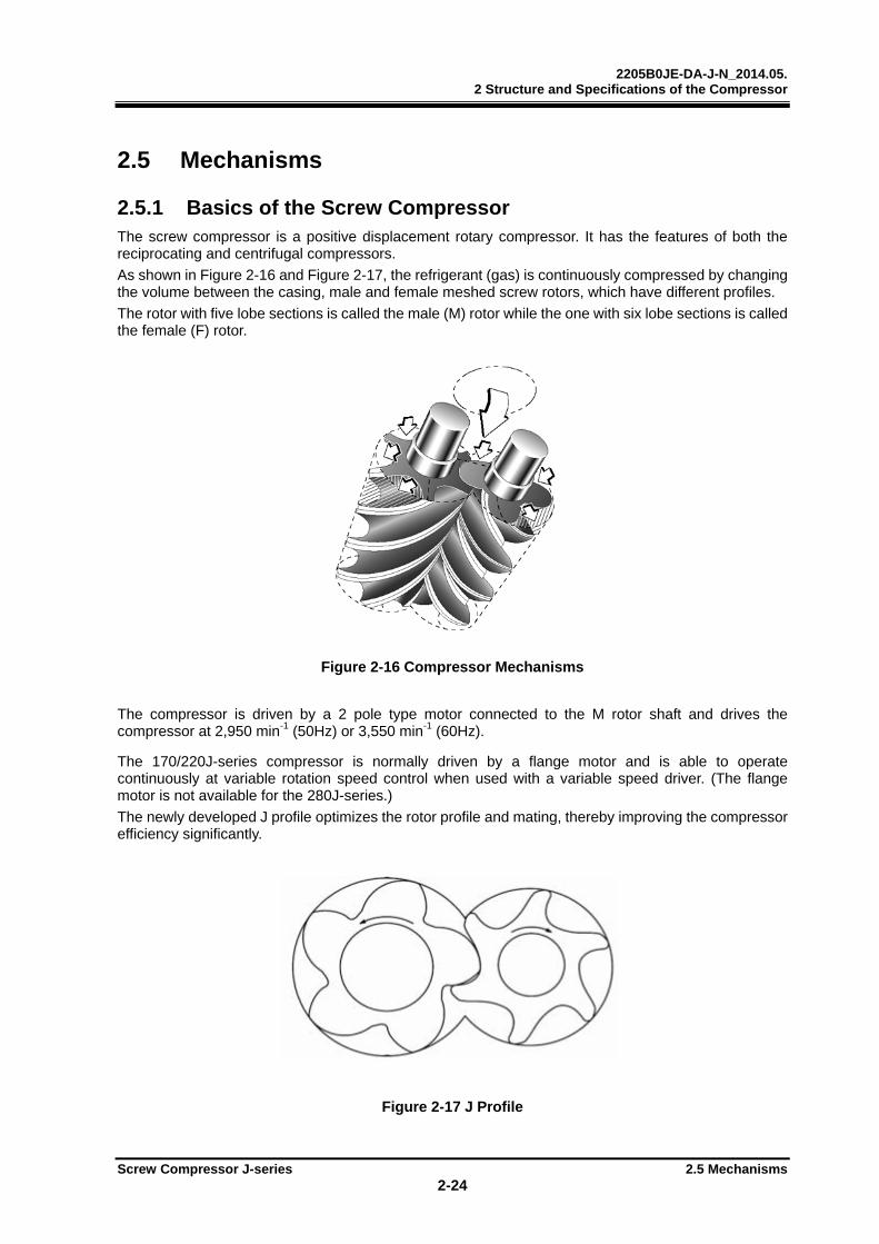
2.5.1 Basics of the Screw Compressor The screw compressor is a positive displacement rotary compressor. It has the features of both the reciprocating and centrifugal compressors.
As shown in Figure 2-16 and Figure 2-17, the refrigerant (gas) is continuously compressed by changing the volume between the casing, male and female meshed screw rotors, which have different profiles.
The rotor with five lobe sections is called the male (M) rotor while the one with six lobe sections is called the female (F) rotor.
Figure 2-16 Compressor Mechanisms
The compressor is driven by a 2 pole type motor connected to the M rotor shaft and drives the compressor at 2,950 min-1 (50Hz) or 3,550 min-1 (60Hz). The 170/220J-series compressor is normally driven by a flange motor and is able to operate continuously at variable rotation speed control when used with a variable speed driver. (The flange motor is not available for the 280J-series.)
The newly developed J profile optimizes the rotor profile and mating, thereby improving the compressor efficiency significantly.
Figure 2-17 J Profile
2205B0JE-DA-J-N_2014.05. 2 Structure and Specifications of the Compressor
Screw Compressor J-series 2.5 Mechanisms 2-25
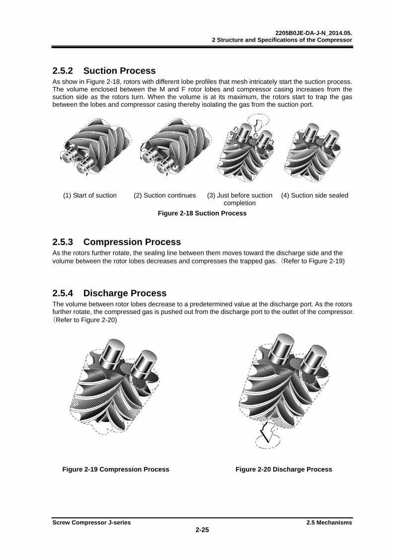
2.5.2 Suction Process As show in Figure 2-18, rotors with different lobe profiles that mesh intricately start the suction process. The volume enclosed between the M and F rotor lobes and compressor casing increases from the suction side as the rotors turn. When the volume is at its maximum, the rotors start to trap the gas between the lobes and compressor casing thereby isolating the gas from the suction port.
(1) Start of suction (2) Suction continues (3) Just before suction completion
(4) Suction side sealed
Figure 2-18 Suction Process
2.5.3 Compression Process As the rotors further rotate, the sealing line between them moves toward the discharge side and the volume between the rotor lobes decreases and compresses the trapped gas. (Refer to Figure 2-19)
2.5.4 Discharge Process The volume between rotor lobes decrease to a predetermined value at the discharge port. As the rotors further rotate, the compressed gas is pushed out from the discharge port to the outlet of the compressor.(Refer to Figure 2-20)
Figure 2-19 Compression Process Figure 2-20 Discharge Process

2205B0JE-DA-J-N_2014.05. 2 Structure and Specifications of the Compressor
Screw Compressor J-series 2.6 Oil Flow 2-26
2.6 Oil Flow
Figure 2-21 Oil Flow (170J/220J-Series)
Figure 2-22 Oil Flow (280J-Series)
2205B0JE-DA-J-N_2014.05. 2 Structure and Specifications of the Compressor
Screw Compressor J-series 2.7 Capacity Control Characteristics 2-27
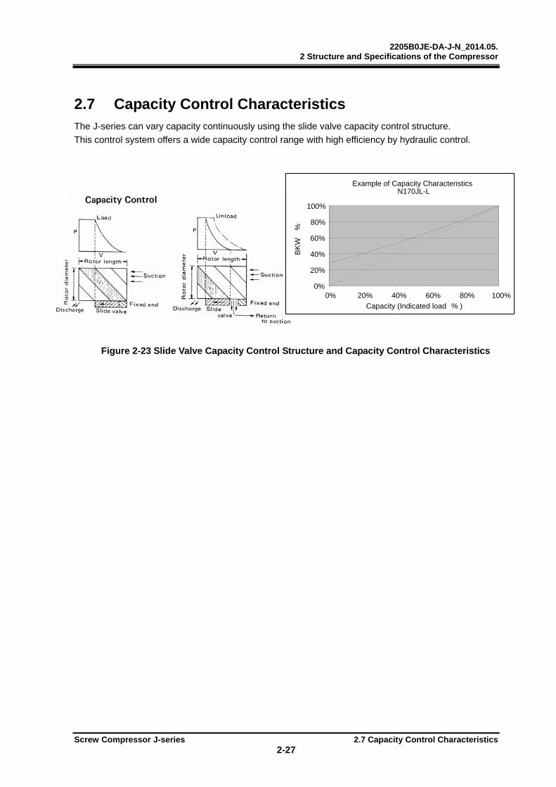
2.7 Capacity Control Characteristics The J-series can vary capacity continuously using the slide valve capacity control structure.
This control system offers a wide capacity control range with high efficiency by hydraulic control.
Figure 2-23 Slide Valve Capacity Control Structure and Capacity Control Characteristics
Example of Capacity CharacteristicsN170JL-L
0%
20%
40%
60%
80%
100%
0% 20% 40% 60% 80% 100%
Capacity (Indicated load % ) B
KW
%
2205B0JE-DA-J-N_2014.05. 2 Structure and Specifications of the Compressor
Screw Compressor J-series 2.8 Variable Vi Control 2-28
2.8 Variable Vi Control
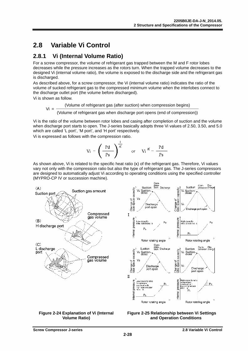
2.8.1 Vi (Internal Volume Ratio) For a screw compressor, the volume of refrigerant gas trapped between the M and F rotor lobes decreases while the pressure increases as the rotors turn. When the trapped volume decreases to the designed Vi (internal volume ratio), the volume is exposed to the discharge side and the refrigerant gas is discharged. As described above, for a screw compressor, the Vi (internal volume ratio) indicates the ratio of the volume of sucked refrigerant gas to the compressed minimum volume when the interlobes connect to the discharge outlet port (the volume before discharged). Vi is shown as follow.
Vi = (Volume of refrigerant gas (after suction) when compression begins)
(Volume of refrigerant gas when discharge port opens (end of compression))
Vi is the ratio of the volume between rotor lobes and casing after completion of suction and the volume when discharge port starts to open. The J-series basically adopts three Vi values of 2.50, 3.50, and 5.0 which are called ‘L port’, ‘M port’, and ‘H port’ respectively. Vi is expressed as follows with the compression ratio.
As shown above, Vi is related to the specific heat ratio (κ) of the refrigerant gas. Therefore, Vi values vary not only with the compression ratio but also the type of refrigerant gas. The J-series compressors are designed to automatically adjust Vi according to operating conditions using the specified controller (MYPRO-CP IV or succession machine).
Figure 2-24 Explanation of Vi (Internal Volume Ratio)
Figure 2-25 Relationship between Vi Settings and Operation Conditions
2205B0JE-DA-J-N_2014.05. 2 Structure and Specifications of the Compressor
Screw Compressor J-series 2.8 Variable Vi Control 2-29
2.8.2 Reasons for Adjusting Vi According to Operating Conditions Operating conditions for the compressor differs with applications. The same compressor may be operated under a variety of pressure conditions such as air conditioning, cold storage and freezing. Also, the discharge pressure may vary depending on the type of condenser or climate conditions. Even in the same application, some conditions may vary. For example, a compressor for air conditioning has different operating conditions for the cooling mode and the heating mode. And a compressor for refrigeration may have different operating conditions depending on the storage room temperature. Compressors are always required to operate with maximum efficiency in these varying operating conditions. For a compressor without a variable Vi mechanism, power is wasted when the fixed Vi does not match the operating conditions (refer to Figure 2-25). For example, if a compressor with a high Vi discharge port (suitable for a high compression ratio) is operated at low compression ratio conditions, the gas between the rotor lobes increases internal pressure to a value higher than the discharge pressure before it is released to the discharge port, this results in extra compression power. On the other hand, if a compressor with a low Vi discharge port is operated at high compression ratio conditions, the gas between the rotor lobes is released to the discharge port before the internal pressure reaches discharge pressure. This results in backflow of the high pressure gas to the discharge side which wastes extra power to push back the backflow gas. These characteristics are inevitable for a fixed Vi screw compressor and become obvious when the discharge port Vi does not match the actual operation conditions. The J-series has a structure that can vary Vi of the discharge port according to operating conditions, therefore, it provides the advantage of operating at a wide range of conditions with high efficiency.
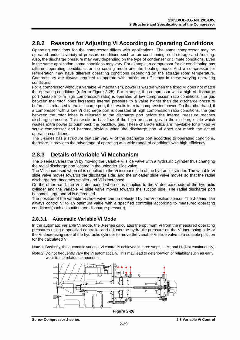
2.8.3 Details of Variable Vi Mechanism The J-series varies the Vi by moving the variable Vi slide valve with a hydraulic cylinder thus changing the radial discharge port located in the unloader slide valve. The Vi is increased when oil is supplied to the Vi increase side of the hydraulic cylinder. The variable Vi slide valve moves towards the discharge side, and the unloader slide valve moves so that the radial discharge port becomes smaller and Vi is increased. On the other hand, the Vi is decreased when oil is supplied to the Vi decrease side of the hydraulic cylinder and the variable Vi slide valve moves towards the suction side. The radial discharge port becomes large and Vi is decreased. The position of the variable Vi slide valve can be detected by the Vi position sensor. The J-series can always control Vi to an optimum value with a specified controller according to measured operating conditions (such as suction and discharge pressure).
2.8.3.1 Automatic Variable Vi Mode In the automatic variable Vi mode, the J-series calculates the optimum Vi from the measured operating pressures using a specified controller and adjusts the hydraulic pressure on the Vi increasing side or the Vi decreasing side of the hydraulic cylinder to move the variable Vi slide valve to a suitable position for the calculated Vi. Note 1: Basically, the automatic variable Vi control is achieved in three steps, L, M, and H.(Not continuously)
Note 2: Do not frequently vary the Vi automatically. This may lead to deterioration of reliability such as early wear to the related components.
Figure 2-26

2205B0JE-DA-J-N_2014.05. 2 Structure and Specifications of the Compressor
Screw Compressor J-series 2.8 Variable Vi Control 2-30
2.8.3.2 Fixed Vi Mode
The J-series also allows for fixed Vi if the operating conditions are stable and the automatic variable Vi control is not necessary.
Note, however, a specified controller is required to adjust the variable Vi slide valve to the desired Vi value. It is able to set Vi to the following three ports: L port (Vi=2.5), M port (Vi=3.5), H port (Vi=5.0).
Note 1: For the J-series, a specified controller is always required.
2.8.4 Vi Position Sensor
Figure 2-27 Vi Sensor Wiring Diagram
Table 2-9 Relationship between Vi and Vi Sensor Output
Port Vi Ratio to ful l stroke (%) Resistance (Ω) Output voltage
rat io (%) L 2.5 0 830 83 M 3.5 56 550 55 H 5.0 100 330 33
Table 2-10 Specifications of the Potentiometer
I tem Specif ications
Total resistance 1kΩ ±20%
Rated power 0.3W/50°C
Insulation resistance 100MΩ or more 500V DC
Withstanding voltage 500V AC for 1 minute
Working temperature range -40—100°C
Figure 2-28 Vi Sensor Dimensions
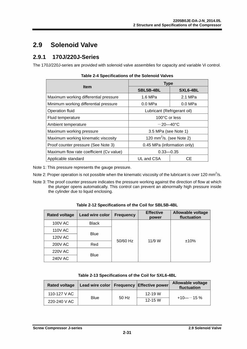
2205B0JE-DA-J-N_2014.05. 2 Structure and Specifications of the Compressor
Screw Compressor J-series 2.9 Solenoid Valve 2-31
2.9 Solenoid Valve
2.9.1 170J/220J-Series The 170J/220J-series are provided with solenoid valve assemblies for capacity and variable Vi control.
Table 2-4 Specifications of the Solenoid Valves
Item Type
SBL5B-4BL SXL6-4BL
Maximum working differential pressure 1.6 MPa 2.1 MPa
Minimum working differential pressure 0.0 MPa 0.0 MPa
Operation fluid Lubricant (Refrigerant oil)
Fluid temperature 100°C or less
Ambient temperature -20—40°C
Maximum working pressure 3.5 MPa (see Note 1)
Maximum working kinematic viscosity 120 mm2/s. (see Note 2)
Proof counter pressure (See Note 3) 0.45 MPa (information only)
Maximum flow rate coefficient (Cv value) 0.33—0.35
Applicable standard UL and CSA CE
Note 1: This pressure represents the gauge pressure.
Note 2: Proper operation is not possible when the kinematic viscosity of the lubricant is over 120 mm2/s.
Note 3: The proof counter pressure indicates the pressure working against the direction of flow at which the plunger opens automatically. This control can prevent an abnormally high pressure inside the cylinder due to liquid enclosing.
Table 2-12 Specifications of the Coil for SBL5B-4BL
Rated voltage Lead wire color FrequencyEffective power
Allowable voltage fluctuation
100V AC Black
50/60 Hz 11/9 W ±10%
110V AC Blue
120V AC
200V AC Red
220V AC Blue
240V AC
Table 2-13 Specifications of the Coil for SXL6-4BL
Rated voltage Lead wire color Frequency Effective powerAllowable voltage
fluctuation
110-127 V AC Blue 50 Hz
12-19 W +10—-15 %
220-240 V AC 12-15 W
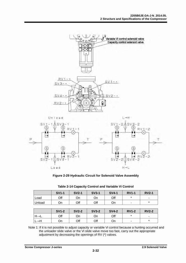
2205B0JE-DA-J-N_2014.05. 2 Structure and Specifications of the Compressor
Screw Compressor J-series 2.9 Solenoid Valve 2-32
Figure 2-29 Hydraulic Circuit for Solenoid Valve Assembly
Table 2-14 Capacity Control and Variable Vi Control
SV1-1 SV2-1 SV3-1 SV4-1 RV1-1 RV2-1
Load Off On On Off * -
Unload On Off Off On - *
SV1-2 SV2-2 SV3-2 SV4-2 RV1-2 RV2-2
H→L Off On On Off * -
L→H On Off Off On - * Note 1: If it is not possible to adjust capacity or variable Vi control because a hunting occurred and
the unloader slide valve or the Vi slide valve move too fast, carry out the appropriate adjustment by decreasing the openings of RV (*) valves.
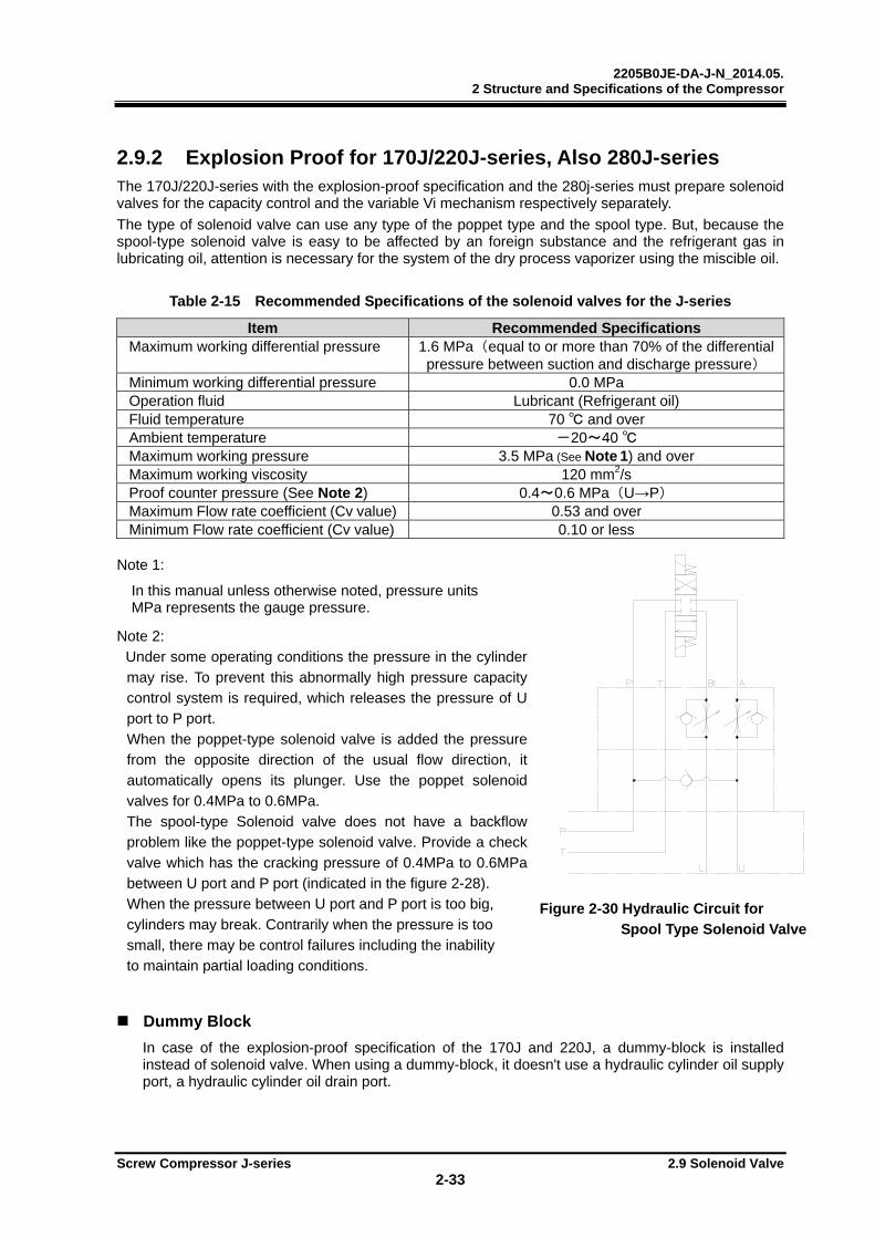
2205B0JE-DA-J-N_2014.05. 2 Structure and Specifications of the Compressor
Screw Compressor J-series 2.9 Solenoid Valve 2-33
2.9.2 Explosion Proof for 170J/220J-series, Also 280J-series The 170J/220J-series with the explosion-proof specification and the 280j-series must prepare solenoid valves for the capacity control and the variable Vi mechanism respectively separately.
The type of solenoid valve can use any type of the poppet type and the spool type. But, because the spool-type solenoid valve is easy to be affected by an foreign substance and the refrigerant gas in lubricating oil, attention is necessary for the system of the dry process vaporizer using the miscible oil.
Table 2-15 Recommended Specifications of the solenoid valves for the J-series
Item Recommended Specifications Maximum working differential pressure 1.6 MPa(equal to or more than 70% of the differential
pressure between suction and discharge pressure) Minimum working differential pressure 0.0 MPa Operation fluid Lubricant (Refrigerant oil) Fluid temperature 70 and over Ambient temperature -20~40 Maximum working pressure 3.5 MPa (See Note 1) and over Maximum working viscosity 120 mm2/s Proof counter pressure (See Note 2) 0.4~0.6 MPa(U→P) Maximum Flow rate coefficient (Cv value) 0.53 and over Minimum Flow rate coefficient (Cv value) 0.10 or less
Note 1:
In this manual unless otherwise noted, pressure units MPa represents the gauge pressure.
Note 2:
Under some operating conditions the pressure in the cylinder
may rise. To prevent this abnormally high pressure capacity control system is required, which releases the pressure of U port to P port.
When the poppet-type solenoid valve is added the pressure from the opposite direction of the usual flow direction, it automatically opens its plunger. Use the poppet solenoid
valves for 0.4MPa to 0.6MPa. The spool-type Solenoid valve does not have a backflow problem like the poppet-type solenoid valve. Provide a check
valve which has the cracking pressure of 0.4MPa to 0.6MPa between U port and P port (indicated in the figure 2-28). When the pressure between U port and P port is too big,
cylinders may break. Contrarily when the pressure is too small, there may be control failures including the inability to maintain partial loading conditions.
Dummy Block
In case of the explosion-proof specification of the 170J and 220J, a dummy-block is installed instead of solenoid valve. When using a dummy-block, it doesn't use a hydraulic cylinder oil supply port, a hydraulic cylinder oil drain port.
Figure 2-30 Hydraulic Circuit for Spool Type Solenoid Valve
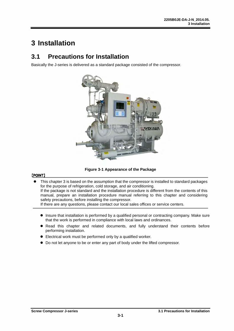
2205B0JE-DA-J-N_2014.05. 3 Installation
Screw Compressor J-series 3.1 Precautions for Installation 3-1
3 Installation
3.1 Precautions for Installation Basically the J-series is delivered as a standard package consisted of the compressor.
Figure 3-1 Appearance of the Package
This chapter 3 is based on the assumption that the compressor is installed to standard packages for the purpose of refrigeration, cold storage, and air conditioning. If the package is not standard and the installation procedure is different from the contents of this manual, prepare an installation procedure manual referring to this chapter and considering safety precautions, before installing the compressor. If there are any questions, please contact our local sales offices or service centers.
Insure that installation is performed by a qualified personal or contracting company. Make sure that the work is performed in compliance with local laws and ordinances.
Read this chapter and related documents, and fully understand their contents before performing installation.
Electrical work must be performed only by a qualified worker.
Do not let anyone to be or enter any part of body under the lifted compressor.

2205B0JE-DA-J-N_2014.05. 3 Installation
Screw Compressor J-series 3.2 Installation Work 3-2
3.2 Installation Work
3.2.1 Unpacking When unpacking the compressor, make sure that the compressor body is not damaged. Check that there are no abnormalities.
If there are abnormalities or deficient parts on the compressor, please contact our local sales offices or service centers immediately.
Unnecessary packaging materials should be discarded according to the laws and ordinances, or your company's rules.
3.2.2 Storage To store the compressor before installation;
Store it indoors.
Seal nitrogen gas in the compressor. (Pressure: approximately 0.15 MPa)
3.2.3 Transfer
Dropping of the lifted compressor may cause death or serious injury to the worker. Do not allow anyone to be under the lifted compressor.
1. To lift the compressor, use lifting equipment with sufficient load for the weight of the compressor and appropriate lifting slings having proof load of more than the weight of compressor.
2. Secure sufficient space for safe lifting.
3. Check the lifting slings before use. Thoroughly check the lifting slings for any problems (such as deformation, knot, wire breakage). Do not start lifting unless the lifting slings are verified that they have no problems. If you cannot make correct evaluation or judgment, entrust an expert to inspect the lifting slings.
4. To lift the compressor, attach the lifting slings to the attached eyebolts using appropriate shackles and hooks. The eyebolts are only used for lifting the compressor. Do not use the eyebolts to lift the compressor with any attached apparatus.
The compressor eyebolts must not be used to lift the package. To lift the package, use the lifting chains on the base periphery or other lifting devices provided on the base.
5. Check the transportation route for any obstacles in consideration of the compressor size.
6. Before lifting, check that the lift hook is located on the vertical line leading from the gravity center of the compressor.
7. Instruct all workers to move from near the work site before lifting.
8. Before lifting the compressor, alert all workers on the site of possible dangers of the lifting process by signal (such as calling at the beginning of the work or making a signal with hand). Remove all nonessential workers from area until lift is complete. Do not lift the compressor unless the signals are completely understood by the all personal working together.
2205B0JE-DA-J-N_2014.05. 3 Installation
Screw Compressor J-series 3.2 Installation Work 3-3
9. Slowly reel up the winch immediately before the compressor is away from the ground.
10. Then, reel up the winch further until the compressor is completely away from the ground and check that the compressor is not inclined. If the compressor is inclined, return the compressor on the ground and correct the inclination by adjusting the lifting slings. Then, restart the lifting operation.
11. Make sure to reel up the compressor slowly. Lifting it too quickly may damage the lifting slings or part of the compressor.
12. After lifting the compressor, check the wire ropes or lift slings. Check that the compressor is held horizontally.
13. When moving the lifted compressor, always use a guiding rope.
14. When moving the compressor, turn away workers from the movement direction and check safety.
15. Do not lift the compressor above any safety passage unless in unavoidable case.
16. Do not put the compressor in a safety passage. Always keep the safety passage free of obstacles.
17. Remove any obstacles before putting down the compressor on the ground. The compressor should not be inclined or unstable.
18. Before putting down the compressor on the ground, announce to the workers around the working area.
19. When lowering the compressor onto two or more blocks, use blocks with the same height so that the compressor is horizontal and stable.
20. Lower the compressor slowly so that it dose not get damaged or collided.
3.2.4 Preparation for Installation
Installation Space Prepare sufficient working space for easy operation, cleaning, maintenance, and inspection.
Illumination Prepare lighting for easy operation, cleaning, maintenance, and inspection.
Ventilation If natural ventilation is insufficient, install ventilation fans according to the regulations.
Piping Refer to "2.3.2 Outer Dimensions" in this manual chapter 2.

2205B0JE-DA-J-N_2014.05. 3 Installation
Screw Compressor J-series 3.2 Installation Work 3-4
3.2.5 Installation
3.2.5.1 Installation
170J/220J-Series The standard 170J/220J-series has a structure coupled with a flange motor. The compressor can only be installed to the motor by connecting with the motor spacer.
For installation of the compressor in the package, the following two cases are assumed: Installing the compressor first (for package manufacturing); Motor and motor spacer are already present on package frame (for compressor maintenance).
The following procedure describes how to install the compressor to the motor spacer for maintenance purposes.
Figure 3-2 Motor Spacer
1. Attach the upper two stud bolts (safety bolts) (M16 × 60) to the bearing cover flange face of the compressor.
2. Lift the compressor horizontally using lifting equipment such as a crane and align the compressor flange to the motor spacer flange by using the stud bolts on the bearing cover as the guide.
3. Insert two hexagon socket head cap screws (M16 × 60) in diagonal positions from the motor spacer side, and tighten them until the flanges are in contact.
4. Apply lubricant (molybdenum disulfide) to the parallel pin (13 dia. × 60) and insert the parallel pin by knocking it with a copper hammer from the motor spacer side.
5. Remove the stud bolts and insert all bolts and tighten them to the specified torque diagonally.
6. Remove the crane used to lift the compressor and check for any gaps between the base of package and the feet of the compressor. If there are any gaps, adjust the compressor height using shims and then fix the compressor to the base with bolts.
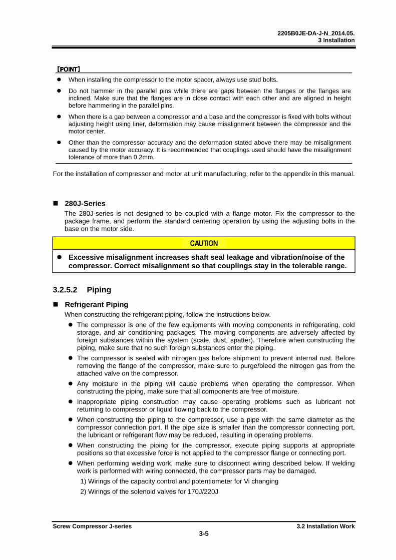
2205B0JE-DA-J-N_2014.05. 3 Installation
Screw Compressor J-series 3.2 Installation Work 3-5
When installing the compressor to the motor spacer, always use stud bolts.
Do not hammer in the parallel pins while there are gaps between the flanges or the flanges are inclined. Make sure that the flanges are in close contact with each other and are aligned in height before hammering in the parallel pins.
When there is a gap between a compressor and a base and the compressor is fixed with bolts without adjusting height using liner, deformation may cause misalignment between the compressor and the motor center.
Other than the compressor accuracy and the deformation stated above there may be misalignment caused by the motor accuracy. It is recommended that couplings used should have the misalignment tolerance of more than 0.2mm.
For the installation of compressor and motor at unit manufacturing, refer to the appendix in this manual.
280J-Series The 280J-series is not designed to be coupled with a flange motor. Fix the compressor to the package frame, and perform the standard centering operation by using the adjusting bolts in the base on the motor side.
Excessive misalignment increases shaft seal leakage and vibration/noise of the compressor. Correct misalignment so that couplings stay in the tolerable range.
3.2.5.2 Piping
Refrigerant Piping When constructing the refrigerant piping, follow the instructions below.
The compressor is one of the few equipments with moving components in refrigerating, cold storage, and air conditioning packages. The moving components are adversely affected by foreign substances within the system (scale, dust, spatter). Therefore when constructing the piping, make sure that no such foreign substances enter the piping.
The compressor is sealed with nitrogen gas before shipment to prevent internal rust. Before removing the flange of the compressor, make sure to purge/bleed the nitrogen gas from the attached valve on the compressor.
Any moisture in the piping will cause problems when operating the compressor. When constructing the piping, make sure that all components are free of moisture.
Inappropriate piping construction may cause operating problems such as lubricant not returning to compressor or liquid flowing back to the compressor.
When constructing the piping to the compressor, use a pipe with the same diameter as the compressor connection port. If the pipe size is smaller than the compressor connecting port, the lubricant or refrigerant flow may be reduced, resulting in operating problems.
When constructing the piping for the compressor, execute piping supports at appropriate positions so that excessive force is not applied to the compressor flange or connecting port.
When performing welding work, make sure to disconnect wiring described below. If welding work is performed with wiring connected, the compressor parts may be damaged.
1) Wirings of the capacity control and potentiometer for Vi changing
2) Wirings of the solenoid valves for 170J/220J
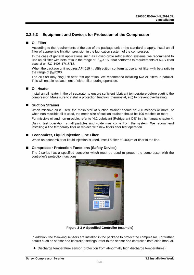
2205B0JE-DA-J-N_2014.05. 3 Installation
Screw Compressor J-series 3.2 Installation Work 3-6
3.2.5.3 Equipment and Devices for Protection of the Compressor
Oil Filter According to the requirements of the use of the package unit or the standard to apply, install an oil filter of appropriate filtration precision in the lubrication system of the compressor.
In the case of general applications such as closed-cycle refrigeration systems, we recommend to use an oil filter with beta ratio in the range of β20 ≥ 150 that conforms to requirements of NAS 1638 class 8 or ISO 4406 17/15/13.
When the package unit requires API 619 4th/5th edition conformity, use an oil filter with beta ratio in the range of β10≥200.
The oil filter may clog just after test operation. We recommend installing two oil filters in parallel. This will enable replacement of either filter during operation.
Oil Heater Install an oil heater in the oil separator to ensure sufficient lubricant temperature before starting the compressor. Make sure to install a protection function (thermostat, etc) to prevent overheating.
Suction Strainer When miscible oil is used, the mesh size of suction strainer should be 200 meshes or more, or when non-miscible oil is used, the mesh size of suction strainer should be 100 meshes or more.
For miscible oil and non-miscible, refer to "4.2 Lubricant (Refrigerant Oil)" in this manual chapter 4.
During test operation, small particles and scale may come from the system. We recommend installing a fine temporally filter or replace with new filters after test operation.
Economizer, Liquid Injection Line Filter When an economizer or liquid injection is used, install a filter of 100μm or finer in the line.
Compressor Protection Functions (Safety Device) The J-series has a specified controller which must be used to protect the compressor with the controller's protection functions.
Figure 3-3 A Specified Controller (example)
In addition, the following sensors are installed in the package to protect the compressor. For further details such as sensor and controller settings, refer to the sensor and controller instruction manual.
Discharge temperature sensor (protection from abnormally high discharge temperatures)
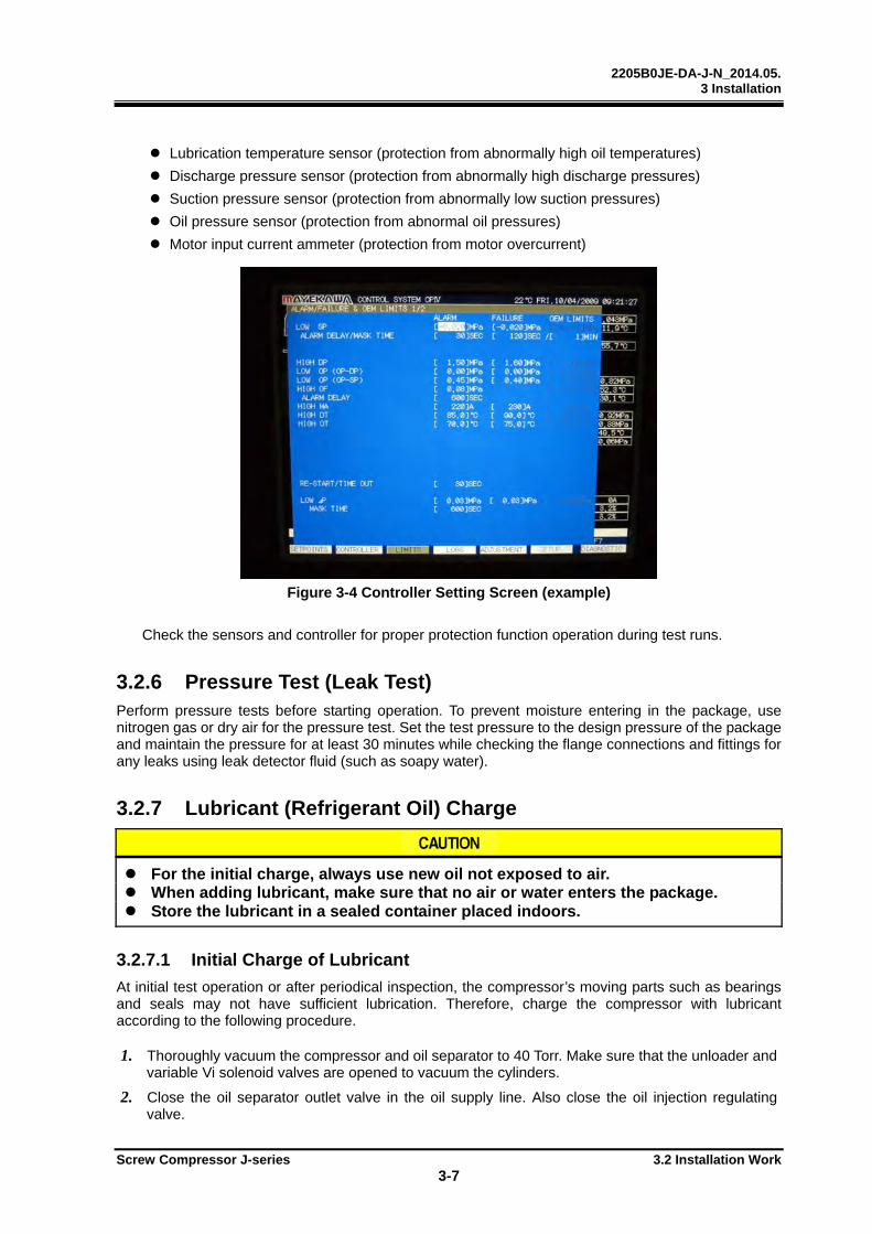
2205B0JE-DA-J-N_2014.05. 3 Installation
Screw Compressor J-series 3.2 Installation Work 3-7
Lubrication temperature sensor (protection from abnormally high oil temperatures)
Discharge pressure sensor (protection from abnormally high discharge pressures)
Suction pressure sensor (protection from abnormally low suction pressures)
Oil pressure sensor (protection from abnormal oil pressures)
Motor input current ammeter (protection from motor overcurrent)
Figure 3-4 Controller Setting Screen (example)
Check the sensors and controller for proper protection function operation during test runs.
3.2.6 Pressure Test (Leak Test) Perform pressure tests before starting operation. To prevent moisture entering in the package, use nitrogen gas or dry air for the pressure test. Set the test pressure to the design pressure of the package and maintain the pressure for at least 30 minutes while checking the flange connections and fittings for any leaks using leak detector fluid (such as soapy water).
3.2.7 Lubricant (Refrigerant Oil) Charge
For the initial charge, always use new oil not exposed to air. When adding lubricant, make sure that no air or water enters the package. Store the lubricant in a sealed container placed indoors.
3.2.7.1 Initial Charge of Lubricant
At initial test operation or after periodical inspection, the compressor’s moving parts such as bearings and seals may not have sufficient lubrication. Therefore, charge the compressor with lubricant according to the following procedure.
1. Thoroughly vacuum the compressor and oil separator to 40 Torr. Make sure that the unloader and variable Vi solenoid valves are opened to vacuum the cylinders.
2. Close the oil separator outlet valve in the oil supply line. Also close the oil injection regulating valve.

2205B0JE-DA-J-N_2014.05. 3 Installation
Screw Compressor J-series 3.2 Installation Work 3-8
3. Charge lubricant from the drain valve on the oil cooler (or on the oil filter) through the compressor to the oil separator.
4. When the oil level reaches to the lower limit of the oil level gauge in the oil separator, stop the charging from the oil supply line. (The approximate amount of refrigerant oil charge is the combined capacity of the oil cooler and oil filter plus at least 20 liter).
5. Then charge oil to the specified level from the oil charging valve on oil separator.
6. Start the oil pump and check the oil pump discharge pressure to confirm that the lubricant flows. When possible, check if the oil level on the oil separator lowers.
7. Adjust the differential pressure between the oil pump discharge and the suction pressure. (Specified differential pressure: 0.2±0.05 MPa). Refer to "2.3 Compressor Specifications" in this manual chapter 2.
8. After adjusting the differential pressure, run the oil pump for 2 minutes. After checking that the motor main power is off, turn the compressor driving shaft manually. About 10 turns using a coupling.
9. If lubricant flows through the oil supply line normally after the above works, the initial lubricant charge is completed.
After the initial charge of lubricant, make sure that the oil cooler and oil filter are filled with lubricant.
For lubricant to be used, refer to "4.1 Lubricant (Refrigerant Oil)" in this manual chapter 4.
For the amount of initial lubricant charge, refer to the package instruction manual.
3.2.7.2 Additional Charge of Lubricant Procedure
For additional charge of lubricant during operation the procedures of charging defer depending on the systems and operating conditions therefore follow the procedures described in the instruction manual of the unit.
For additional lubricant charge, always use the same brand of oil with the same viscosity grade as that already charged in the package. The use of any other brand or viscosity grade may cause operation problems.
3.2.8 Charging of Refrigerant As with the lubricant charge, charging of the refrigerant must be performed carefully so that no moisture or air enters the system.
For further details on refrigerant charging works, refer to the package or refrigeration unit instruction manual.
3.2.9 Check after Installation Perform the checks after compressor installation according to the check list in the package instruction manual.

2205B0JE-DA-J-N_2014.05. 3 Installation
Screw Compressor J-series 3.3 Documents Related to Installation 3-9
3.3 Documents Related to Installation
Lifting Positions/Gravity Center Positions/Lifted View
Figure 3-5 Center of Gravity and Lifting Points (170J)

2205B0JE-DA-J-N_2014.05. 3 Installation
Screw Compressor J-series 3.3 Documents Related to Installation 3-10
Figure 3-6 Center of Gravity and Lifting Points (220J)
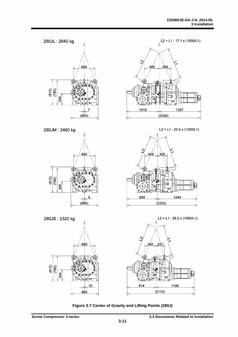
2205B0JE-DA-J-N_2014.05. 3 Installation
Screw Compressor J-series 3.3 Documents Related to Installation 3-11
Figure 3-7 Center of Gravity and Lifting Points (280J)
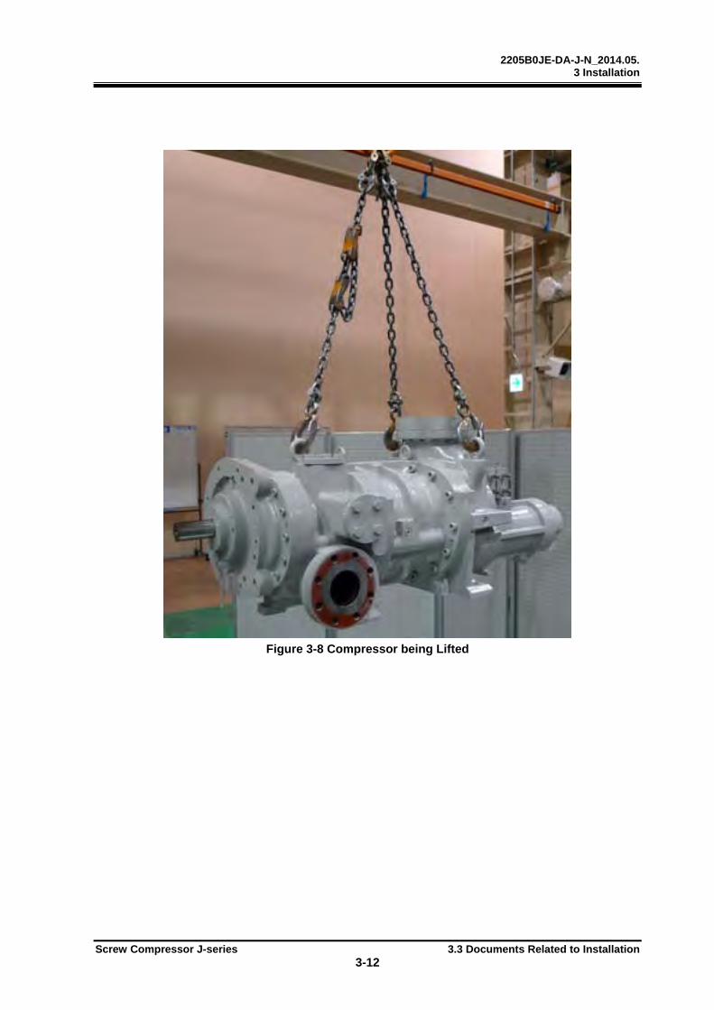
2205B0JE-DA-J-N_2014.05. 3 Installation
Screw Compressor J-series 3.3 Documents Related to Installation 3-12
Figure 3-8 Compressor being Lifted
2205B0JE-DA-J-N_2014.05. 4 Compressor and Package Operation
Screw Compressor J-series 4.1 Adjustment before Test Operation
4-1
4 Compressor and Package Operation
4.1 Adjustment before Test Operation The unloader slide valve and variable Vi valve must be set by the controller before test operation.
4.1.1 Adjustment of Unloader Slide Valve and Variable Vi Slide Valve
Before test operation, make sure to perform a set-up that allows the controller to learn unloader slide valve positions from the 0% to 100%(indicated load) and variable Vi valve positions from the 2.5 to 5.0.
During the setup, make sure to operate the oil pump only. Turn off the main power for the compressor motor.
During the setup, make sure to keep the internal pressure of the compressor less than 1.5 MPa (gauge pressure).
After the setup operation, equalize pressure by opening the suction stop valve slowly in the package. After opening the suction stop valve, make sure that the motor main power is off and then turn the compressor driving shaft manually.
1. Close the suction stop valve of the package.
2. Confirm that the internal compressor pressure is less than 1.5MPa (gauge pressure). If the pressure in the compressor is high, setup work of the Vi slide valve becomes difficult to perform accurately.
3. To check the unloader solenoid valve operation, start the oil pump and adjust the pressure. Set the oil pump discharge pressure 0.2 MPa (+/-0.05 MPa) higher than the oil pump suction pressure.
4. Using the controller manually, press the increase button of the unloader solenoid valve to increase the load of the unloader slide valve and check if the indicator needle moves toward the 100% point.
5. If the indicator needle moves in the increasing direction, the unloader solenoid valve wiring is correct.
6. If the indicator needle moves reversely or does not move, check the unloader solenoid valve wiring.
7. Next, operate the variable Vi slide valve to the L-Port position using the controller and check the variable Vi slide valve moving direction on the controller display.
8. If the variable Vi slide valve moves to the L-Port direction, the variable Vi solenoid valve wiring is correct. If it does not move or moves in the reverse direction, check the wiring.
9. If the unloader slide valve and variable Vi slide valve move in the correct directions respectively, execute the initial set up mode for the unloader slide valve and the variable Vi slide valve by the controller.
10. The oil pump automatically starts and the unloader slide valve and variable Vi slide valve automatically move in increasing direction and decreasing directions to allow operational position check.
With these steps, the initial adjustment for the unloader slide valve and the variable Vi slide valve is completed.
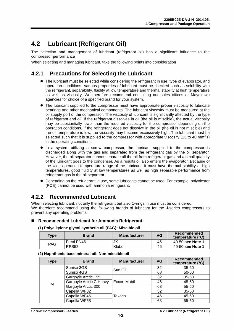
2205B0JE-DA-J-N_2014.05. 4 Compressor and Package Operation
Screw Compressor J-series 4.2 Lubricant (Refrigerant Oil)
4-2
4.2 Lubricant (Refrigerant Oil) The selection and management of lubricant (refrigerant oil) has a significant influence to the compressor performance
When selecting and managing lubricant, take the following points into consideration
4.2.1 Precautions for Selecting the Lubricant The lubricant must be selected while considering the refrigerant in use, type of evaporator, and
operation conditions. Various properties of lubricant must be checked such as solubility with the refrigerant, separability, fluidity at low temperature and thermal stability at high temperature as well as viscosity. We therefore recommend consulting our sales offices or Mayekawa agencies for choice of a specified brand for your system.
The lubricant supplied to the compressor must have appropriate proper viscosity to lubricate bearings and other mechanical components. The lubricant viscosity must be measured at the oil supply port of the compressor. The viscosity of lubricant is significantly affected by the type of refrigerant and oil. If the refrigerant dissolves in oil (the oil is miscible), the actual viscosity may be substantially lower than the required viscosity for the compressor depending on the operation conditions. If the refrigerant does not dissolve in the oil (the oil is not miscible) and the oil temperature is low, the viscosity may become excessively high. The lubricant must be selected such that it is supplied to the compressor with appropriate viscosity (13 to 40 mm2/s) in the operating conditions.
In a system utilizing a screw compressor, the lubricant supplied to the compressor is discharged along with the gas and separated from the refrigerant gas by the oil separator. However, the oil separator cannot separate all the oil from refrigerant gas and a small quantity of the lubricant goes to the condenser. As a results oil also enters the evaporator. Because of the wide operation temperature range of the lubricant, it must have thermal stability at high temperatures, good fluidity at low temperatures as well as high separable performance from refrigerant gas in the oil separator.
Depending on the refrigerant in use, some lubricants cannot be used. For example, polyolester (POE) cannot be used with ammonia refrigerant.
4.2.2 Recommended Lubricant When selecting lubricant, not only the refrigerant but also O-rings in use must be considered. We therefore recommend using the following brands of lubricant for the J-series compressors to prevent any operating problems.
Recommended Lubricant for Ammonia Refrigerant
(1) Polyalkylene glycol synthetic oil (PAG): Miscible oil
Type Brand Manufacturer VG Recommended temperature (°C)
PAG Freol PN46 JX 46 40-50 see Note 1 RPS52 Kluber 46 40-50 see Note 1
(2) Naphthenic base mineral oil: Non-miscible oil
Type Brand Manufacturer VG Recommended temperature (°C)
M
Suniso 3GS Sun Oil
32 35-60 Suniso 4GS 68 50-60 Gargoyle Arctic 155
Exxon Mobil 32 35-60
Gargoyle Arctic C Heavy 46 45-60 Gargoyle Arctic 300 68 55-60 Capella WF32
Texaco 32 35-60
Capella WF46 46 45-60 Capella WF68 68 55-60
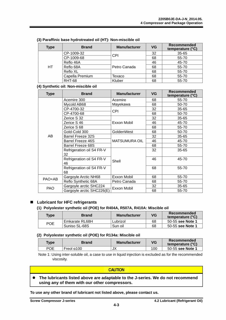
2205B0JE-DA-J-N_2014.05. 4 Compressor and Package Operation
Screw Compressor J-series 4.2 Lubricant (Refrigerant Oil)
4-3
(3) Paraffinic base hydrotreated oil (HT): Non-miscible oil
Type Brand Manufacturer VG Recommended temperature (°C)
HT
CP-1009-32 CPI
32 35-65 CP-1009-68 68 55-70 Reflo 46A
Petro Canada 46 45-70
Reflo 68A 68 55-70 Reflo XL 68 55-70 Capella Premium Texaco 68 55-70 RHT-68 Kluber 68 55-70
(4) Synthetic oil: Non-miscible oil
Type Brand Manufacturer VG Recommended temperature (°C)
AB
Acemire 300 Acemire Mayekawa
68 55-70 Mycold AB68 68 50-70 CP-4700-32
CPI 32 35-65
CP-4700-68 68 50-70 Zerice S 32
Exxon Mobil 32 35-65
Zerice S 46 46 45-70 Zerice S 68 68 55-70 Gold-Cold 300 GoldenWest 68 50-70 Barrel Freeze 32S
MATSUMURA OIL32 35-65
Barrel Freeze 46S 46 45-70 Barrel Freeze 68S 68 55-70 Refrigeration oil S4 FR-V 32
Shell
32 35-65
Refrigeration oil S4 FR-V 46
46 45-70
Refrigeration oil S4 FR-V 68
68 55-70
PAO+AB Gargoyle Arctic NH68 Exxon Mobil 68 55-70 Reflo Synthetic 68A Petro Canada 68 55-70
PAO Gargoyle arctic SHC224
Exxon Mobil 32 35-65
Gargoyle arctic SHC226(E) 68 55-70
Lubricant for HFC refrigerants (1) Polyolester synthetic oil (POE) for R404A, R507A, R410A: Miscible oil
Type Brand Manufacturer VG Recommended temperature (°C)
POE Emkarate RL68H Lubrizol 68 50-55 see Note 1 Suniso SL-68S Sun oil 68 50-55 see Note 1
(2) Polyolester synthetic oil (POE) for R134a: Miscible oil
Type Brand Manufacturer VG Recommended temperature (°C)
POE Freol α100 JX 100 50-55 see Note 1
Note 1: Using inter-soluble oil, a case to use in liquid injection is excluded as for the recommendedviscosity.
The lubricants listed above are adaptable to the J-series. We do not recommend using any of them with our other compressors.
To use any other brand of lubricant not listed above, please contact us.
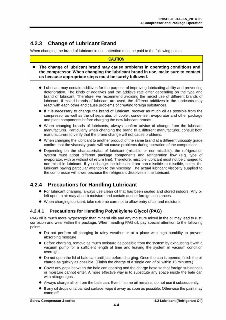
2205B0JE-DA-J-N_2014.05. 4 Compressor and Package Operation
Screw Compressor J-series 4.2 Lubricant (Refrigerant Oil)
4-4
4.2.3 Change of Lubricant Brand When changing the brand of lubricant in use, attention must be paid to the following points.
The change of lubricant brand may cause problems in operating conditions and the compressor. When changing the lubricant brand in use, make sure to contact us because appropriate steps must be surely followed.
Lubricant may contain additives for the purpose of improving lubricating ability and preventing deterioration. The kinds of additives and the additive rate differ depending on the type and brand of lubricant. Therefore, we recommend avoiding the mixed use of different brands of lubricant. If mixed brands of lubricant are used, the different additives in the lubricants may react with each other and cause problems of creating foreign substances.
If it is necessary to change the brand of lubricant, recover as much oil as possible from the compressor as well as the oil separator, oil cooler, condenser, evaporator and other package and plant components before charging the new lubricant brands.
When changing brands of lubricants, always confirm advice of change from the lubricant manufacturer. Particularly when changing the brand to a different manufacturer, consult both manufacturers to verify that the brand change will not cause problems.
When changing the lubricant to another product of the same brand at a different viscosity grade, confirm that the viscosity grade will not cause problems during operation of the compressor.
Depending on the characteristics of lubricant (miscible or non-miscible), the refrigeration system must adopt different package components and refrigeration flow (e.g. type of evaporator, with or without oil return line). Therefore, miscible lubricant must not be changed to non-miscible lubricant. If you change the lubricant from non-miscible to miscible, select the lubricant paying particular attention to the viscosity. The actual lubricant viscosity supplied to the compressor will lower because the refrigerant dissolves in the lubricant.
4.2.4 Precautions for Handling Lubricant For lubricant charging, always use clean oil that has been sealed and stored indoors. Any oil
left open to air may absorb moisture and contain dust or foreign substances.
When charging lubricant, take extreme care not to allow entry of air and moisture.
4.2.4.1 Precautions for Handling Polyalkylene Glycol (PAG)
PAG oil is much more hygroscopic than mineral oils and any moisture mixed in the oil may lead to rust, corrosion and wear within the package. When handling PAG oil, pay special attention to the following points.
Do not perform oil charging in rainy weather or at a place with high humidity to prevent absorbing moisture.
Before charging, remove as much moisture as possible from the system by exhausting it with a vacuum pump for a sufficient length of time and leaving the system in vacuum condition overnight.
Do not open the lid of bale can until just before charging. Once the can is opened, finish the oil charge as quickly as possible. (Finish the charge of a single can of oil within 15 minutes.)
Cover any gaps between the bale can opening and the charge hose so that foreign substances or moisture cannot enter. A more effective way is to substitute any space inside the bale can with nitrogen gas .
Always charge all oil from the bale can. Even if some oil remains, do not use it subsequently.
If any oil drops on a painted surface, wipe it away as soon as possible. Otherwise the paint may come off.
2205B0JE-DA-J-N_2014.05. 4 Compressor and Package Operation
Screw Compressor J-series 4.2 Lubricant (Refrigerant Oil)
4-5
4.2.4.2 Precautions for Handling Polyolester (POE) Oil
This type of oil has high hygroscopicity as polyalkylene glycol, and also exhibits hydrolyzability under high temperature environments. Moisture entry must be avoided. Therefore, special attention must be paid as with PAG when handling POE.
Finish the charging in as short a time as possible after opening the bale can to minimize exposure to air.
Make sure that all oil in a bale can is used in a single charging. Any remaining oil must be stored indoors with the can lid closed tightly. Do not attempt to store it for a long time.
Because POE can hydrolyze, make sure to perform an oil analysis regularly in the package to see if any abnormal conditions are present.

2205B0JE-DA-J-N_2014.05. 4 Compressor and Package Operation
Screw Compressor J-series 4.3 Precautions for Operation
4-6
4.3 Precautions for Operation
4.3.1 Prevention of Liquid Return (Liquid Backflow) Operation Liquid return is a phenomenon where refrigerant liquid (mist) is not completely evaporated within the evaporator and is drawn into the compressor.
Liquid return may cause abnormal vibrations and noises from compressor, foaming of lubricant in the oil separator (too much entry of oil), and poor lubrication of compressor.
To prevent liquid return, appropriately adjust the expansion valve to the evaporator or liquid cooler. In addition, special attention must be paid to the suction pipe line connection way to the system and means of starting up the compressor after a long time of stoppage.
4.3.2 Purging of Non-condensable Gases Any non-condensable gas in the system may cause the compressor discharge pressure to rise higher than the refrigerant saturation pressure that depends on cooling water temperature of condenser. This is caused by the non-condensable gas staying in the condenser which deteriorates the heat exchange performance.
If the vacuum pumping performed upon initial installation or maintenance is insufficient or the suction pressure is lower than the atmospheric pressure to suck air if the suction pipe had a leak, non-condensable gases accumulate in the condenser.
When a considerable amount of non-condensable gases accumulate in the condenser, the compressor load increases and finally the motor overcurrent alarm may occur.
In such a case, purge any non-condensable gas from the condenser.
Some types of refrigerants may have bad smell, toxicity, and/or flammability. In a airtight space such as a machine room, oxygen shortage may occur due to high concentration of the refrigerant gas. Maintain sufficient ventilation while working.
When handling fluorocarbon refrigerants, remember that they are prohibited from being purged into air by law.
1. When the compressor is stopped, allow the cooling water to flow to the condenser and check that there is no difference in water temperature between the inlet and outlet. If any difference is present between the inlet and outlet water temperatures, keep the cooling water flowing until the temperature difference is eliminated.
2. Measure the pressure of the condenser and compare it with the refrigerant saturation pressure depending on the cooling water temperature.
3. If the condenser pressure is higher than the refrigerant saturation pressure by 0.05 MPa or more, purge any non-condensable gases.
2205B0JE-DA-J-N_2014.05. 4 Compressor and Package Operation
Screw Compressor J-series 4.4 Action for Stopping the Compressor for Long Period of Time
4-7
4.4 Action for Stopping the Compressor for Long Period of Time
Before stopping the compressor for a long time, make sure to perform the following steps.
Turn off the main motor power.
Turn off the oil heater power and the control power.
Close the suction stop valve and discharge stop valve.
If an economizer or liquid injection is used, close the stop valve located at the compressor inlet.
If the stoppage period is 1 month or longer, perform the following checks every month.
Measure the package pressure.
Check for refrigerant leak using a leakage detector.
Operate the oil pump for 5 minutes. After that, turn the compressor driving shaft manually. (10 turns or more)
When restarting the compressor after a stoppage period of 1 year or longer, check the package for refrigerant leakage and replace the lubricant. Also check the main motor for insulation resistance.
Supply power to the oil heater for at least 1 hour before operation starts. And before starting the operation, confirm that the refrigerant is not condensed in the package by checking the package temperature and pressure (especially the suction pipe).
2205B0JE-DA-J-N_2014.05. 5 Maintenance and Inspection
Screw Compressor J-series 5.1 Precautions for Maintenance and Inspection
5-1
5 Maintenance and Inspection
5.1 Precautions for Maintenance and Inspection Before starting maintenance/inspection work after completely removing the refrigerant from the
package, make sure that the main motor, control and power for instruments and valves are turned off and the power off switches are protected from any unauthorized access. In addition, attach a tag to each power off switch informing other workers that the switch must not be turned on. (Lockout/tagout)
Also when a manual valve is closed, apply appropriate measures so that it cannot be operated by other workers and attach a tag stating that the device must not be opened.
Before disassembling, inspecting or handling the compressor, fully understand the disassembly/assembly procedure of the compressor. This document does not provide the complete procedures of compressor disassembly and assembly but just instructs the main points in compressor service.
If you need to perform the complete compressor disassembly/assembly work, consult in your region.
When replacing any parts with the compressor, always use the genuine parts. If any unauthentic part is used, unexpected problems may occur.
Do not modify the compressor or any of its parts without prior permission of Mayekawa. It may cause the compressor to be damaged or disabled from maintaining its normal functions.
To disassemble the compressor, it must be removed from the package and placed on a work bench. Before removing the compressor from the package, make sure to remove the refrigerant in the package and confirm that the pressure inside the compressor is atmospheric.
Prior to removing the compressor from the package, check that the high temperature side (discharge side) is cooled down to 40°C or less.
Perform the compressor disassembly on a rigid and flat work bench.
When removing the compressor from the package and placing it on the work bench, follow the instructions in Chapter 3, "3.1 Precautions for Installation" and "3.2.3 Transfer".
Lifting and carrying works for the compressor and package must be performed by a qualified person.
For compressor disassembly/assembly, use specified tools that are properly functioning.
When handling heavy parts, exercise extreme caution and use safe auxiliary tools such as safety bolts.
When carrying a heavy part, use lifting equipment such as crane, or work with one or more workers.
Before working with other workers, make sure that all workers clearly understand the work procedure.
When turning on and off the power supplies, take care to avoid any electric shock hazard.
Any electric works requiring some expert qualifications must be performed by a qualified person.

2205B0JE-DA-J-N_2014.05. 5 Maintenance and Inspection
Screw Compressor J-series 5.2 Maintenance List
5-2
5.2 Maintenance List
5.2.1 Daily Management The controller panel installed to the compressor package in standard displays the following items that monitor the compressor operating conditions.
Suction pressure (MPa)
Discharge pressure (MPa)
Lubrication pressure (MPa)
Oil filter pressure loss (MPa)
Suction temperature (°C)
Discharge temperature (°C)
Oil supply temperature (°C)
Motor current (A)
Indicated load of unloader (%)
Compressor Vi setting (-)
Suction superheat (°C)
Discharge superheat (°C)
Note: Unless otherwise noted, the pressure unit MPa represents the gauge pressure in this manual.
These operation data should be recorded in an operating log book on a daily basis. This practice is significantly effective and helpful in finding out any abnormal condition of the compressor and prevents possible compressor failures.
In particular, it is important to confirm the absence of any abnormality between the temperature and pressure correlations related to the refrigerant evaporation and condensation. It is possible to find any abnormal condition in the compressor or the system quickly by monitoring the evaporation and condensation temperature and pressure.
If any compressor/system failure or operating accident occurs, the operating log book will help the cause to be clear and take appropriate measures promptly.
Figure 5-1 Controller Display Screen (Example)

2205B0JE-DA-J-N_2014.05. 5 Maintenance and Inspection
Screw Compressor J-series 5.2 Maintenance List
5-3
Daily inspection items Based on the operating log, check the following points.
Table 5-1 Daily Inspection Items
Inspection Items Inspection Contents Check Items/Actions
Com
pres
sor Operating hours h Total operating hours Judgment of periodic
maintenance timing Suction pressure
MPa Note 1
Difference from the set value of evaporation temperature equivalent pressure
Contamination on the cooling pipe surface
Temperature, flow rate, etc. of the object to be cooled
Discharge pressure Mpa Difference from cooling water temperature equivalent condensing pressure
Contamination on condenser cooling pipes
Non-condensable gases mixed into the system
Quantity, temperature, etc. of cooling water
Oil supply pressure MPa Difference from discharge pressure
Whether differential pressure is decreasing
Operation with liquid flow-back Whether compressor parts are
worn Oil filter pressure loss MPa Pressure difference between
oil filter inlet and outlet Contamination of lubricant Clogging of oil filter
Suction temperature °C Whether within upper and lower limits
Temperature, flow rate, etc. of the object to be cooled
Degree of superheat for suction
°C Whether degree of superheat is proper
Adjust expansion valve Insufficient refrigerant flow
Discharge temperature
°C Whether within upper limit Non-condensable gases mixed into the system
Oil supply temperature, insufficient oil supply
Compressor failure
Oil supply temperature
°C Whether within upper and lower limits
Contamination on cooling pipes of oil cooler
Capacity control Indicated load
%
Whether operation is normal Damage to solenoid valve coil Improper adjustment of manual
control valve of electromagnetic assembly
Leak from mechanical seal
mL/h Leak per hour Mechanical seal failure
Variable Vi valve position (L, M, H)
Whether port position is appropriate for operating conditions
Damaged solenoid valve coil Position sensor failure
Noise and vibration Abnormal noise/vibration Compressor failure
Oth
ers Motor current A Whether it is higher than the
current at test run Compressor failure Motor failure
Oil level of oil separator
- Oil level Oil loss Replenish oil
Fluid level in the receiver
- Fluid level Replenish refrigerant
Check for refrigerant leak
-
leak or not The machine room and the load side facilities
Note 1 : Unless otherwise noted, the pressure unit MPa represents the gauge pressure in this manual.
Com
pres
sor
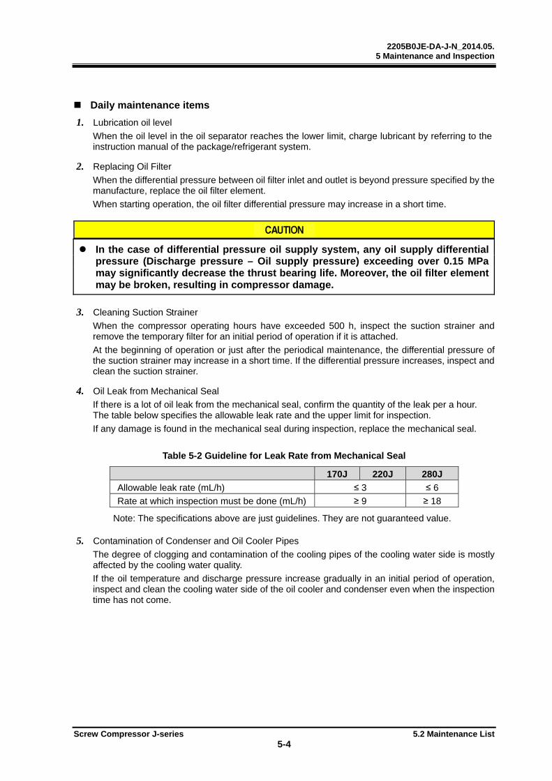
2205B0JE-DA-J-N_2014.05. 5 Maintenance and Inspection
Screw Compressor J-series 5.2 Maintenance List
5-4
Daily maintenance items
1. Lubrication oil level
When the oil level in the oil separator reaches the lower limit, charge lubricant by referring to the instruction manual of the package/refrigerant system.
2. Replacing Oil Filter
When the differential pressure between oil filter inlet and outlet is beyond pressure specified by the manufacture, replace the oil filter element.
When starting operation, the oil filter differential pressure may increase in a short time.
In the case of differential pressure oil supply system, any oil supply differential pressure (Discharge pressure – Oil supply pressure) exceeding over 0.15 MPa may significantly decrease the thrust bearing life. Moreover, the oil filter element may be broken, resulting in compressor damage.
3. Cleaning Suction Strainer
When the compressor operating hours have exceeded 500 h, inspect the suction strainer and remove the temporary filter for an initial period of operation if it is attached.
At the beginning of operation or just after the periodical maintenance, the differential pressure of the suction strainer may increase in a short time. If the differential pressure increases, inspect and clean the suction strainer.
4. Oil Leak from Mechanical Seal
If there is a lot of oil leak from the mechanical seal, confirm the quantity of the leak per a hour. The table below specifies the allowable leak rate and the upper limit for inspection.
If any damage is found in the mechanical seal during inspection, replace the mechanical seal.
Table 5-2 Guideline for Leak Rate from Mechanical Seal
170J 220J 280J
Allowable leak rate (mL/h) ≤ 3 ≤ 6
Rate at which inspection must be done (mL/h) ≥ 9 ≥ 18 Note: The specifications above are just guidelines. They are not guaranteed value.
5. Contamination of Condenser and Oil Cooler Pipes
The degree of clogging and contamination of the cooling pipes of the cooling water side is mostly affected by the cooling water quality.
If the oil temperature and discharge pressure increase gradually in an initial period of operation, inspect and clean the cooling water side of the oil cooler and condenser even when the inspection time has not come.
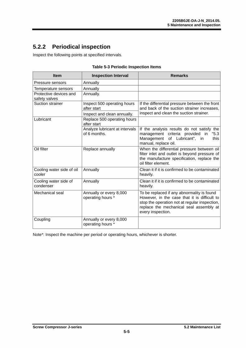
2205B0JE-DA-J-N_2014.05. 5 Maintenance and Inspection
Screw Compressor J-series 5.2 Maintenance List
5-5
5.2.2 Periodical inspection Inspect the following points at specified intervals.
Table 5-3 Periodic Inspection Items
Item Inspection Interval Remarks
Pressure sensors Annually
Temperature sensors Annually Protective devices and safety valves
Annually.
Suction strainer Inspect 500 operating hours after start
If the differential pressure between the front and back of the suction strainer increases, inspect and clean the suction strainer. Inspect and clean annually.
Lubricant Replace 500 operating hours after start
Analyze lubricant at intervals of 6 months.
If the analysis results do not satisfy the management criteria provided in "5.3 Management of Lubricant", in this manual, replace oil.
Oil filter Replace annually When the differential pressure between oil filter inlet and outlet is beyond pressure of the manufacture specification, replace the oil filter element.
Cooling water side of oil cooler
Annually Clean it if it is confirmed to be contaminated heavily.
Cooling water side of condenser
Annually Clean it if it is confirmed to be contaminated heavily.
Mechanical seal Annually or every 8,000 operating hours *
To be replaced if any abnormality is found However, in the case that it is difficult to stop the operation not at regular inspection, replace the mechanical seal assembly at every inspection.
Coupling Annually or every 8,000 operating hours *
Note*: Inspect the machine per period or operating hours, whichever is shorter.
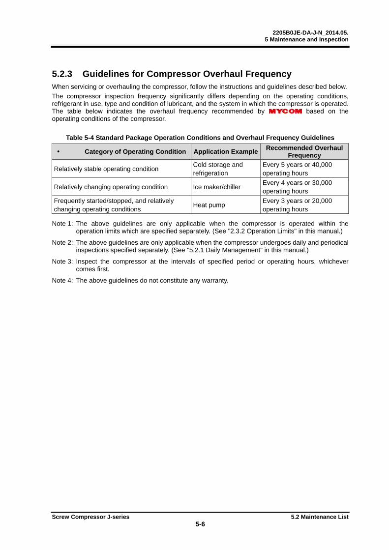
2205B0JE-DA-J-N_2014.05. 5 Maintenance and Inspection
Screw Compressor J-series 5.2 Maintenance List
5-6
5.2.3 Guidelines for Compressor Overhaul Frequency When servicing or overhauling the compressor, follow the instructions and guidelines described below.
The compressor inspection frequency significantly differs depending on the operating conditions, refrigerant in use, type and condition of lubricant, and the system in which the compressor is operated. The table below indicates the overhaul frequency recommended by based on the operating conditions of the compressor.
Table 5-4 Standard Package Operation Conditions and Overhaul Frequency Guidelines
Category of Operating Condition Application ExampleRecommended Overhaul
Frequency
Relatively stable operating condition Cold storage and refrigeration
Every 5 years or 40,000 operating hours
Relatively changing operating condition Ice maker/chiller Every 4 years or 30,000 operating hours
Frequently started/stopped, and relatively changing operating conditions
Heat pump Every 3 years or 20,000 operating hours
Note 1: The above guidelines are only applicable when the compressor is operated within the
operation limits which are specified separately. (See "2.3.2 Operation Limits" in this manual.)
Note 2: The above guidelines are only applicable when the compressor undergoes daily and periodical inspections specified separately. (See "5.2.1 Daily Management" in this manual.)
Note 3: Inspect the compressor at the intervals of specified period or operating hours, whichever comes first.
Note 4: The above guidelines do not constitute any warranty.
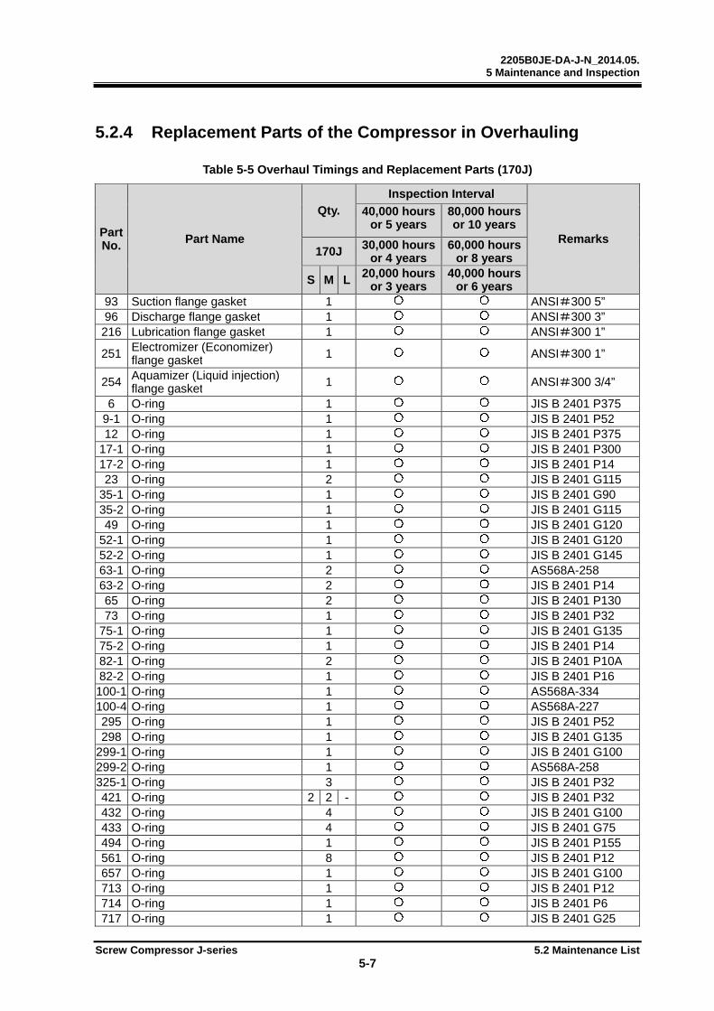
2205B0JE-DA-J-N_2014.05. 5 Maintenance and Inspection
Screw Compressor J-series 5.2 Maintenance List
5-7
5.2.4 Replacement Parts of the Compressor in Overhauling
Table 5-5 Overhaul Timings and Replacement Parts (170J)
Part No. Part Name
Qty.
Inspection Interval
Remarks
40,000 hoursor 5 years
80,000 hours or 10 years
170J 30,000 hoursor 4 years
60,000 hours or 8 years
S M L 20,000 hoursor 3 years
40,000 hours or 6 years
93 Suction flange gasket 1 ANSI#300 5”96 Discharge flange gasket 1 ANSI#300 3”216 Lubrication flange gasket 1 ANSI#300 1”
251 Electromizer (Economizer) flange gasket 1 ANSI#300 1”
254 Aquamizer (Liquid injection) flange gasket 1 ANSI#300 3/4”
6 O-ring 1 JIS B 2401 P3759-1 O-ring 1 JIS B 2401 P5212 O-ring 1 JIS B 2401 P375
17-1 O-ring 1 JIS B 2401 P30017-2 O-ring 1 JIS B 2401 P1423 O-ring 2 JIS B 2401 G115
35-1 O-ring 1 JIS B 2401 G9035-2 O-ring 1 JIS B 2401 G115 49 O-ring 1 JIS B 2401 G120
52-1 O-ring 1 JIS B 2401 G12052-2 O-ring 1 JIS B 2401 G14563-1 O-ring 2 AS568A-25863-2 O-ring 2 JIS B 2401 P1465 O-ring 2 JIS B 2401 P13073 O-ring 1 JIS B 2401 P32
75-1 O-ring 1 JIS B 2401 G13575-2 O-ring 1 JIS B 2401 P1482-1 O-ring 2 JIS B 2401 P10A82-2 O-ring 1 JIS B 2401 P16100-1 O-ring 1 AS568A-334100-4 O-ring 1 AS568A-227295 O-ring 1 JIS B 2401 P52298 O-ring 1 JIS B 2401 G135
299-1 O-ring 1 JIS B 2401 G100299-2 O-ring 1 AS568A-258325-1 O-ring 3 JIS B 2401 P32421 O-ring 2 2 - JIS B 2401 P32432 O-ring 4 JIS B 2401 G100433 O-ring 4 JIS B 2401 G75494 O-ring 1 JIS B 2401 P155561 O-ring 8 JIS B 2401 P12657 O-ring 1 JIS B 2401 G100713 O-ring 1 JIS B 2401 P12714 O-ring 1 JIS B 2401 P6717 O-ring 1 JIS B 2401 G25

2205B0JE-DA-J-N_2014.05. 5 Maintenance and Inspection
Screw Compressor J-series 5.2 Maintenance List
5-8
Part No. Part Name
Qty.
Inspection Interval
Remarks
40,000 hoursor 5 years
80,000 hours or 10 years
170J 30,000 hoursor 4 years
60,000 hours or 8 years
S M L 20,000 hoursor 3 years
40,000 hours or 6 years
744 O-ring 1 JIS B 2401 G559-2 Back-up ring for O-ring 2 SUN-2BP 52
325-2 Back-up ring for O-ring 2 SUN-2BP 3266 Teflon cap seal 2 SUNR-BE-13050 Oil seal 1 SA1J 65 85 12100 Mechanical seal assembly 1 38-1 Thrust bearing assembly, M 1 7312BEAXT7DF38-2 Thrust bearing assembly, F 1 7309BEAXT7DF40-1 Lock washer 1 AW12 40-2 Lock washer 1 AW09
46 Conical spring washer 12 Hexagon socket head cap screw M8
237-1 Torsional slip washer 1 237-2 Torsional slip washer 1 293 Spiral retaining ring 2 FRSN-45 489 Valve sheet 1 485 Spring, check valve 1 711 Spring 1
27 Bearing for M rotor 2 Reusable if not damaged.
28 Bearing for F rotor 2 Reusable if not damaged.
481 Check valve slider 1 Reusable if not damaged.
486 Locknut 1 FU nut FU04SSReusable if not damaged.
487 Plain washer 1
JIS B 1256, small dia. M20 Reusable if not damaged.
491 Check valve stem 1 Reusable if not damaged.
528 Sleeve, oil seal 1 Reusable if not damaged.
712 Vi position sensor rod 1 Reusable if not damaged.
30 Balance piston 1 To be replaced if there is any damage.
33 Balance piston sleeve 1 To be replaced if there is any damage.
29-1 Retaining ring C type - Internal 2
JIS B 2804 H120To be replaced if there is any damage.
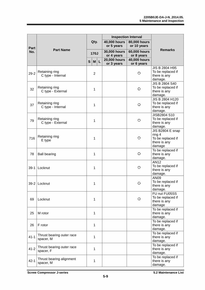
2205B0JE-DA-J-N_2014.05. 5 Maintenance and Inspection
Screw Compressor J-series 5.2 Maintenance List
5-9
Part No. Part Name
Qty.
Inspection Interval
Remarks
40,000 hoursor 5 years
80,000 hours or 10 years
170J 30,000 hoursor 4 years
60,000 hours or 8 years
S M L 20,000 hoursor 3 years
40,000 hours or 6 years
29-2 Retaining ring C type - Internal 2
JIS B 2804 H95To be replaced if there is any damage.
32 Retaining ring C type - External 1
JIS B 2804 S40To be replaced if there is any damage.
37 Retaining ring C type - Internal 1
JIS B 2804 H120To be replaced if there is any damage.
79 Retaining ring C type - External 1
JISB2804 S10To be replaced if there is any damage.
716 Retaining ring E type 1
JIS B2804 E snap ring 4 To be replaced if there is any damage
78 Ball bearing 1 To be replaced if there is any damage.
39-1 Locknut 1
AN12 To be replaced if there is any damage.
39-2 Locknut 1
AN09 To be replaced if there is any damage.
69 Locknut 1
FU nut FU05SSTo be replaced if there is any damage
25 M rotor 1 To be replaced if there is any damage.
26 F rotor 1 To be replaced if there is any damage.
41-1 Thrust bearing outer race spacer, M 1
To be replaced if there is any damage.
41-2 Thrust bearing outer race spacer, F 1
To be replaced if there is any damage.
42-1 Thrust bearing alignment spacer, M 1
To be replaced if there is any damage.
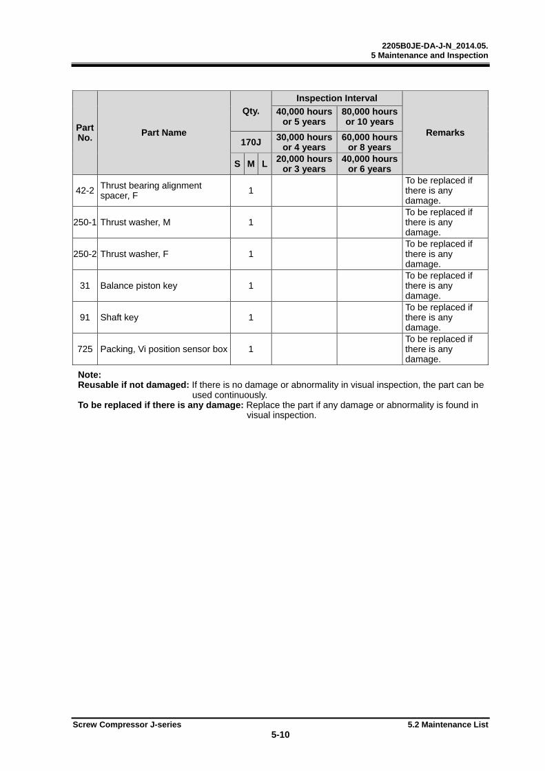
2205B0JE-DA-J-N_2014.05. 5 Maintenance and Inspection
Screw Compressor J-series 5.2 Maintenance List
5-10
Part No. Part Name
Qty.
Inspection Interval
Remarks
40,000 hoursor 5 years
80,000 hours or 10 years
170J 30,000 hoursor 4 years
60,000 hours or 8 years
S M L 20,000 hoursor 3 years
40,000 hours or 6 years
42-2 Thrust bearing alignment spacer, F 1
To be replaced if there is any damage.
250-1 Thrust washer, M 1 To be replaced if there is any damage.
250-2 Thrust washer, F 1 To be replaced if there is any damage.
31 Balance piston key 1 To be replaced if there is any damage.
91 Shaft key 1 To be replaced if there is any damage.
725 Packing, Vi position sensor box 1 To be replaced if there is any damage.
Note: Reusable if not damaged: If there is no damage or abnormality in visual inspection, the part can be
used continuously. To be replaced if there is any damage: Replace the part if any damage or abnormality is found in
visual inspection.

2205B0JE-DA-J-N_2014.05. 5 Maintenance and Inspection
Screw Compressor J-series 5.2 Maintenance List
5-11
Table 5-6 Overhaul Timings and Replacement Parts (220J)
Part No. Part Name
Qty.
Inspection Interval
Remarks
40,000 hoursor 5 years
80,000 hours or 10 years
220J 30,000 hoursor 4 years
60,000 hours or 8 years
S M L 20,000 hoursor 3 years
40,000 hours or 6 years
93 Suction flange gasket 1 ANSI#300 8”96 Discharge flange gasket 1 ANSI#300 5”216 Oil supply flange gasket 1 ANSI#300 1”
251 Electromizer (Economizer) flange gasket 1 ANSI#300 1 1/2”
254 Aquamizer (Liquid injection) flange gasket 1 ANSI#300 3/4”
6 O-ring 1 JIS B 2401 P4509-1 O-ring 1 JIS B 2401 P6512 O-ring 1 JIS B 2401 P450
17-1 O-ring 1 JIS B 2401 P37517-2 O-ring 1 JIS B 2401 P1423-1 O-ring 1 JIS B 2401 G15023-2 O-ring 1 JIS B 2401 G11535-1 O-ring 1 JIS B 2401 P12035-2 O-ring 1 JIS B 2401 G150 49 O-ring 1 JIS B 2401 G145
52-1 O-ring 1 JIS B 2401 G14552-2 O-ring 1 JIS B 2401 P1463-1 O-ring 2 JIS B 2401 G20063-2 O-ring 2 JIS B 2401 P1465 O-ring 2 JIS B 2401 P17073 O-ring 1 JIS B 2401 P44
75-1 O-ring 1 JIS B 2401 G17575-2 O-ring 1 JIS B 2401 P1482-1 O-ring 2 JIS B 2401 P10A82-2 O-ring 1 JIS B 2401 P16100-1 O-ring 1 AS568A-340100-4 O-ring 1 AS568A-148295 O-ring 1 JIS B 2401 P65298 O-ring 1 JIS B 2401 G175
299-1 O-ring 1 JIS B 2401 G100299-2 O-ring 1 JIS B 2401 G200325-1 O-ring 3 JIS B 2401 P44421 O-ring 2 2 - JIS B 2401 P44432 O-ring 4 JIS B 2401 G130433 O-ring 4 JIS B 2401 G100494 O-ring 1 JIS B 2401 P220561 O-ring 8 JIS B 2401 P12657 O-ring 1 JIS B 2401 G120713 O-ring 1 JIS B 2401 P12714 O-ring 1 JIS B 2401 P6717 O-ring 1 JIS B 2401 G25
728-4 O-ring 1 JIS B 2401 G45
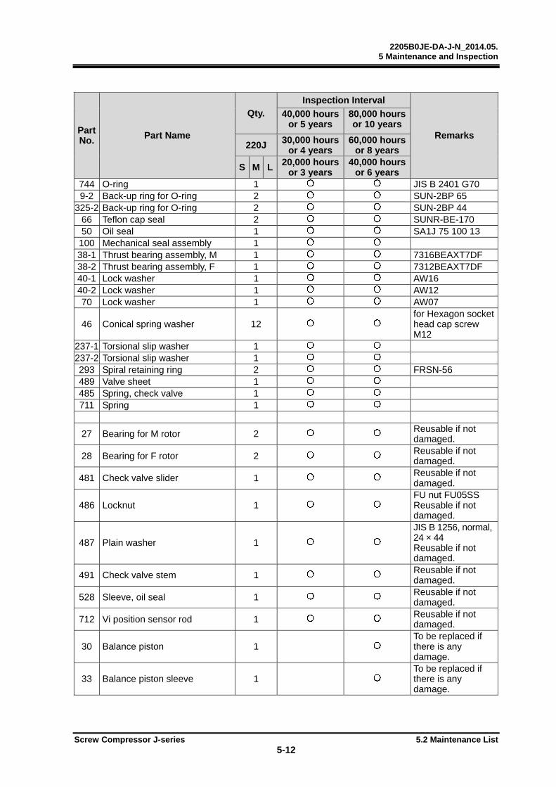
2205B0JE-DA-J-N_2014.05. 5 Maintenance and Inspection
Screw Compressor J-series 5.2 Maintenance List
5-12
Part No. Part Name
Qty.
Inspection Interval
Remarks
40,000 hoursor 5 years
80,000 hours or 10 years
220J 30,000 hoursor 4 years
60,000 hours or 8 years
S M L 20,000 hoursor 3 years
40,000 hours or 6 years
744 O-ring 1 JIS B 2401 G709-2 Back-up ring for O-ring 2 SUN-2BP 65
325-2 Back-up ring for O-ring 2 SUN-2BP 4466 Teflon cap seal 2 SUNR-BE-17050 Oil seal 1 SA1J 75 100 13100 Mechanical seal assembly 1 38-1 Thrust bearing assembly, M 1 7316BEAXT7DF38-2 Thrust bearing assembly, F 1 7312BEAXT7DF40-1 Lock washer 1 AW16 40-2 Lock washer 1 AW12 70 Lock washer 1 AW07
46 Conical spring washer 12 for Hexagon socket head cap screw M12
237-1 Torsional slip washer 1 237-2 Torsional slip washer 1 293 Spiral retaining ring 2 FRSN-56 489 Valve sheet 1 485 Spring, check valve 1 711 Spring 1
27 Bearing for M rotor 2 Reusable if not damaged.
28 Bearing for F rotor 2 Reusable if not damaged.
481 Check valve slider 1 Reusable if not damaged.
486 Locknut 1 FU nut FU05SSReusable if not damaged.
487 Plain washer 1
JIS B 1256, normal, 24 × 44 Reusable if not damaged.
491 Check valve stem 1 Reusable if not damaged.
528 Sleeve, oil seal 1 Reusable if not damaged.
712 Vi position sensor rod 1 Reusable if not damaged.
30 Balance piston 1 To be replaced if there is any damage.
33 Balance piston sleeve 1 To be replaced if there is any damage.
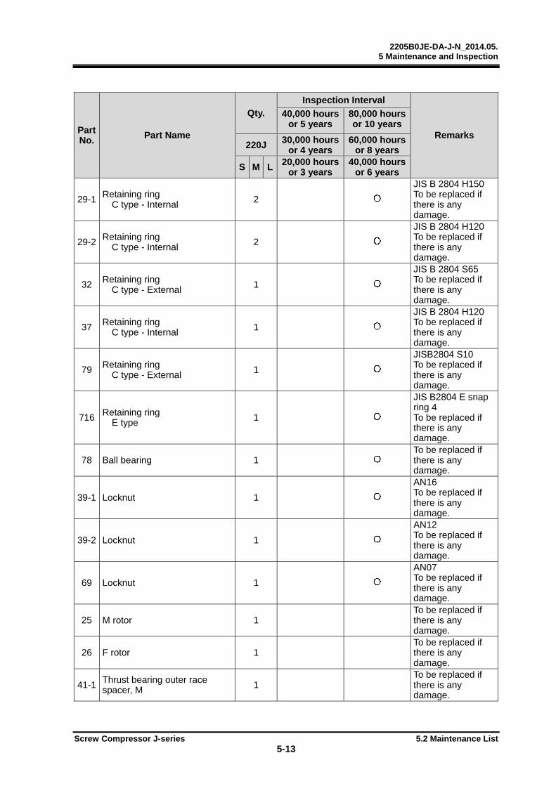
2205B0JE-DA-J-N_2014.05. 5 Maintenance and Inspection
Screw Compressor J-series 5.2 Maintenance List
5-13
Part No. Part Name
Qty.
Inspection Interval
Remarks
40,000 hoursor 5 years
80,000 hours or 10 years
220J 30,000 hoursor 4 years
60,000 hours or 8 years
S M L 20,000 hoursor 3 years
40,000 hours or 6 years
29-1 Retaining ring C type - Internal 2
JIS B 2804 H150To be replaced if there is any damage.
29-2 Retaining ring C type - Internal 2
JIS B 2804 H120To be replaced if there is any damage.
32 Retaining ring C type - External 1
JIS B 2804 S65To be replaced if there is any damage.
37 Retaining ring C type - Internal 1
JIS B 2804 H120To be replaced if there is any damage.
79 Retaining ring C type - External 1
JISB2804 S10To be replaced if there is any damage.
716 Retaining ring E type 1
JIS B2804 E snap ring 4 To be replaced if there is any damage.
78 Ball bearing 1 To be replaced if there is any damage.
39-1 Locknut 1
AN16 To be replaced if there is any damage.
39-2 Locknut 1
AN12 To be replaced if there is any damage.
69 Locknut 1
AN07 To be replaced if there is any damage.
25 M rotor 1 To be replaced if there is any damage.
26 F rotor 1 To be replaced if there is any damage.
41-1 Thrust bearing outer race spacer, M 1
To be replaced if there is any damage.
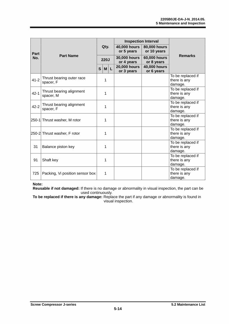
2205B0JE-DA-J-N_2014.05. 5 Maintenance and Inspection
Screw Compressor J-series 5.2 Maintenance List
5-14
Part No. Part Name
Qty.
Inspection Interval
Remarks
40,000 hoursor 5 years
80,000 hours or 10 years
220J 30,000 hoursor 4 years
60,000 hours or 8 years
S M L 20,000 hoursor 3 years
40,000 hours or 6 years
41-2 Thrust bearing outer race spacer, F 1
To be replaced if there is any damage.
42-1 Thrust bearing alignment spacer, M 1
To be replaced if there is any damage.
42-2 Thrust bearing alignment spacer, F 1
To be replaced if there is any damage.
250-1 Thrust washer, M rotor 1 To be replaced if there is any damage.
250-2 Thrust washer, F rotor 1 To be replaced if there is any damage.
31 Balance piston key 1 To be replaced if there is any damage.
91 Shaft key 1 To be replaced if there is any damage.
725 Packing, Vi position sensor box 1 To be replaced if there is any damage.
Note: Reusable if not damaged: If there is no damage or abnormality in visual inspection, the part can be
used continuously. To be replaced if there is any damage: Replace the part if any damage or abnormality is found in
visual inspection.
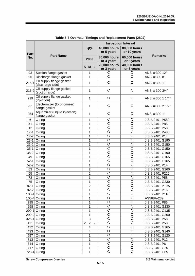
2205B0JE-DA-J-N_2014.05. 5 Maintenance and Inspection
Screw Compressor J-series 5.2 Maintenance List
5-15
Table 5-7 Overhaul Timings and Replacement Parts (280J)
Part No. Part Name
Qty.
Inspection Interval
Remarks
40,000 hoursor 5 years
80,000 hours or 10 years
280J 30,000 hoursor 4 years
60,000 hours or 8 years
S M L 20,000 hoursor 3 years
40,000 hours or 6 years
93 Suction flange gasket 1 ANSI#300 12”96 Discharge flange gasket 1 ANSI#300 8”
216-1 Oil supply flange gasket (discharge side) 1 ANSI#300 1”
216-2 Oil supply flange gasket (suction side) 1 ANSI#300 3/4”
219 Oil supply flange gasket (injection) 1 ANSI#300 1 1/4”
251 Electromizer (Economizer) flange gasket 1 ANSI#300 2 1/2”
254 Aquamizer (Liquid injection) flange gasket 1 ANSI#300 1”
6 O-ring 1 JIS B 2401 P5809-1 O-ring 1 JIS B 2401 P8512 O-ring 1 JIS B 2401 P580
17-1 O-ring 1 JIS B 2401 P48017-2 O-ring 1 JIS B 2401 P1423-1 O-ring 1 JIS B 2401 G19023-2 O-ring 1 JIS B 2401 G15035-1 O-ring 1 JIS B 2401 G15035-2 O-ring 1 JIS B 2401 G190 49 O-ring 1 JIS B 2401 G165
52-1 O-ring 1 JIS B 2401 G16552-2 O-ring 1 JIS B 2401 P1463 O-ring 2 JIS B 2401 G26065 O-ring 2 JIS B 2401 P22573 O-ring 1 JIS B 2401 P5875 O-ring 1 JIS B 2401 G230
82-1 O-ring 2 JIS B 2401 P10A82-2 O-ring 1 JIS B 2401 P16100-1 O-ring 1 JIS B 2401 P110100-4 O-ring 1 AS568A-239295 O-ring 1 JIS B 2401 P85298 O-ring 1 JIS B 2401 G230
299-1 O-ring 1 JIS B 2401 G135299-2 O-ring 1 JIS B 2401 G260325-1 O-ring 3 JIS B 2401 P58421 O-ring 2 2 - JIS B 2401 P58432 O-ring 4 JIS B 2401 G165433 O-ring 4 JIS B 2401 G140657 O-ring 1 JIS B 2401 G120713 O-ring 1 JIS B 2401 P12714 O-ring 1 JIS B 2401 P6717 O-ring 1 JIS B 2401 G25
728-4 O-ring 1 JIS B 2401 G65
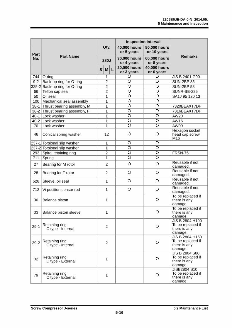
2205B0JE-DA-J-N_2014.05. 5 Maintenance and Inspection
Screw Compressor J-series 5.2 Maintenance List
5-16
Part No. Part Name
Qty.
Inspection Interval
Remarks
40,000 hoursor 5 years
80,000 hours or 10 years
280J 30,000 hoursor 4 years
60,000 hours or 8 years
S M L 20,000 hoursor 3 years
40,000 hours or 6 years
744 O-ring 1 JIS B 2401 G909-2 Back-up ring for O-ring 2 SUN-2BP 85
325-2 Back-up ring for O-ring 2 SUN-2BP 5866 Teflon cap seal 2 SUNR-BE-22550 Oil seal 1 SA1J 95 120 13100 Mechanical seal assembly 1 38-1 Thrust bearing assembly, M 1 7320BEAXT7DF38-2 Thrust bearing assembly, F 1 7316BEAXT7DF40-1 Lock washer 1 AW20 40-2 Lock washer 1 AW16 70 Lock washer 1 AW09
46 Conical spring washer 12 Hexagon socket head cap screw M16
237-1 Torsional slip washer 1 237-2 Torsional slip washer 1 293 Spiral retaining ring 2 FRSN-75 711 Spring 1
27 Bearing for M rotor 2 Reusable if not damaged.
28 Bearing for F rotor 2 Reusable if not damaged.
528 Sleeve, oil seal 1 Reusable if not damaged.
712 Vi position sensor rod 1 Reusable if not damaged.
30 Balance piston 1 To be replaced if there is any damage.
33 Balance piston sleeve 1 To be replaced if there is any damage.
29-1 Retaining ring C type - Internal 2
JIS B 2804 H190To be replaced if there is any damage.
29-2 Retaining ring C type - Internal 2
JIS B 2804 H150To be replaced if there is any damage.
32 Retaining ring C type - External 1
JIS B 2804 S80To be replaced if there is any damage.
79 Retaining ring C type - External 1
JISB2804 S10To be replaced if there is any damage .
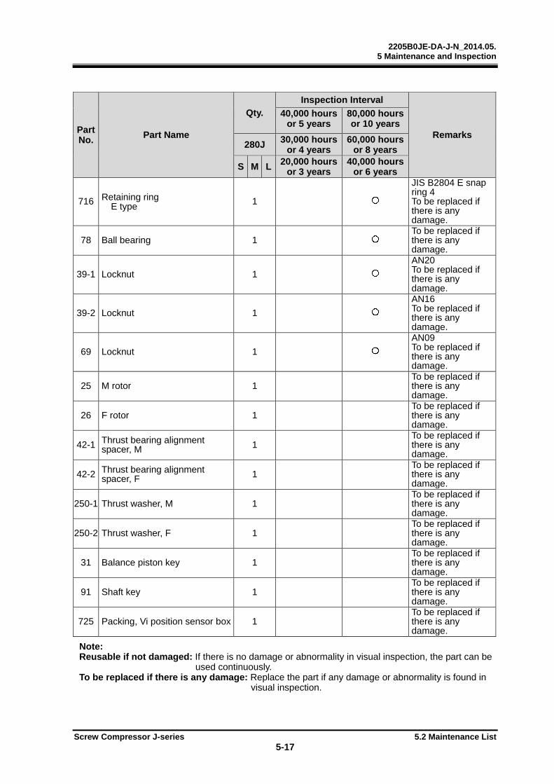
2205B0JE-DA-J-N_2014.05. 5 Maintenance and Inspection
Screw Compressor J-series 5.2 Maintenance List
5-17
Part No. Part Name
Qty.
Inspection Interval
Remarks
40,000 hoursor 5 years
80,000 hours or 10 years
280J 30,000 hoursor 4 years
60,000 hours or 8 years
S M L 20,000 hoursor 3 years
40,000 hours or 6 years
716 Retaining ring E type 1
JIS B2804 E snap ring 4 To be replaced if there is any damage.
78 Ball bearing 1 To be replaced if there is any damage.
39-1 Locknut 1 AN20 To be replaced if there is any damage.
39-2 Locknut 1 AN16 To be replaced if there is any damage.
69 Locknut 1 AN09 To be replaced if there is any damage.
25 M rotor 1 To be replaced if there is any damage.
26 F rotor 1 To be replaced if there is any damage.
42-1 Thrust bearing alignment spacer, M 1
To be replaced if there is any damage.
42-2 Thrust bearing alignment spacer, F 1
To be replaced if there is any damage.
250-1 Thrust washer, M 1 To be replaced if there is any damage.
250-2 Thrust washer, F 1 To be replaced if there is any damage.
31 Balance piston key 1 To be replaced if there is any damage.
91 Shaft key 1 To be replaced if there is any damage.
725 Packing, Vi position sensor box 1 To be replaced if there is any damage.
Note: Reusable if not damaged: If there is no damage or abnormality in visual inspection, the part can be
used continuously. To be replaced if there is any damage: Replace the part if any damage or abnormality is found in
visual inspection.

2205B0JE-DA-J-N_2014.05. 5 Maintenance and Inspection
Screw Compressor J-series 5.3 Management of Lubricant
5-18
5.3 Management of Lubricant
5.3.1 Lubricant Management Standard The lubricant, to which the management standard is applied, is classified as follows: (1) Synthetic oil: Polyalkylene Glycol (PAG)
(2) Mineral oil: Naphthenic base, Paraffinic base
Synthetic oil: Alkyl benzene (AB), Polyalphaolefin (PAO)
(3) Synthetic oil: Polyolester (POE)
We recommend analyzing oil by sampling at intervals of 6 months.
If the oil does not satisfy the management standards below, replace the oil. (This does not apply to water contents in PAG oil)
The evaluation items and standards are as follows. The management standards may be changed without notice.
Table 5-8 Synthetic oil (PAG)
Item Management Standards (a) Color ASTM color standard: 4.0 or less (b) Total acid number 0.1 mg•KOH/g or less (c) Kinematic viscosity Amount of change must be within ±10% from that of the new oil. (d) Water content 2000 ppm or less Note 1 (e) Contamination level Contamination measured by gravimetric analysis (millipore filter value) is
15 mg/100 mL or less.
Table 5-9 Mineral oil, synthetic oil (AB, PAO)
Item Management Standards (a) Color ASTM color standard: 6.0 or less (b) Total acid number 0.3 mg•KOH/g or less (c) Kinematic viscosity Amount of change must be within ±15% from that of the new oil. (d) Water content 100 ppm or less Note 1 (e) Contamination level Contamination measured by gravimetric analysis (millipore filter value) is
15 mg/100 mL or less.
Table 5-10 Synthetic Oil (POE)
Item Management Standards (a) Color ASTM color standard: 4.0 or less (b) Total acid number 0.2 mg•KOH/g or less (c) Kinematic viscosity Amount of change must be within ±10% relative to the new oil. (d) Water content 200 ppm or less (e) Contamination level Contamination measured by gravimetric analysis (millipore filter value) is
15 mg/100 mL or less. Note 1: Lubricant miscible with ammonia has high hygroscopicity and may contain water during
sampling. In addition, ammonia dissolved in the lubricant may be detected as water when it is analyzed, thereby preventing correct measurement of water content. Therefore, the management standards above should be construed as guidelines.

2205B0JE-DA-J-N_2014.05. 5 Maintenance and Inspection
Screw Compressor J-series 5.3 Management of Lubricant
5-19
5.3.2 Replacement Interval for Lubricant
5.3.2.1 First system startup
When the system is started up for the first time, the lubricant may get contaminated or deteriorate due to scale inside the piping and vessels. For the first system start up, replace the lubricant 500 hours after operation.
If the results do not meet the management standards for each oil type detailed in tables 5-8 to 5-10, replace the lubricant.
5.3.2.2 During normal operation
Lubricant gradually degrades when used for a long term.
Though, the degradation rate differs depending on the operating conditions, oil type, and any foreign substances or water in the oil.
Sample and analyze the lubricant every 6 months and if the results do not meet the management criteria for each oil type detailed in tables 5-8 to 5-10, replace the lubricant. However, if the oil filter is clogging frequently or the oil becomes black and opaque, replace the oil after confirming and eliminating the cause.
2205B0JE-DA-J-N_2014.05. 5 Maintenance and Inspection
Screw Compressor J-series 5.4 Disassembly and Assembly of the Compressor
5-20
5.4 Disassembly and Assembly of the Compressor This chapter describes that the text in parentheses after the part name indicates size, length, etc. Also, these texts indicate size, length, etc in the order of the model shown in the upper left of the illustrated parts breakdown.
5.4.1 Tools for Disassembly and Work Place
For compressor disassembly/assembly work, use specified tools that are properly functioning. Using tools that are worn or damaged or that are inappropriate for the work, can result in injury.
Prepare tools to be required for the work referring to “7.4 Tools for Disassembly.” It is also recommended to prepare general hand tools, green silicon carbide grinding stone, emery paper(#80-#100), emery paper(over #800), parts cleaning oil, lubrication oil, a lubricator, an oil can for oil sump, waste cloth and so on. When removing the compressor from the installation flame and doing an overhaul, prepare a large surface plate as the work bench. To safely perform bolts and plugs removal used in the lower side of the compressor, an exclusive frame for placing the compressor is required. Refer to the article 5.4.5 in this chapter. Perform the work in a dry place with as little sand and dust as possible, with a sufficiently wide space around there.
5.4.2 Replacement Parts Prepare genuine replacement parts referring to "5.2.4 Replacement Parts of the compressor in overhauling" in this chapter and "7.1 Development View and Configuration Table " in this manual Chapter 7.
Because O-rings and gaskets which are removed for the inspection are easy to be damaged, replace all with new ones. When purchasing any part, inform its (a) model, (b) serial number, (c) part name, (d) code No. and (e) necessary number to our sales offices or service centers. Especially when the (b) serial number of the compressor is not identified, it will be difficult to decide the required parts because we can not specify the design and manufacturing specifications.
5.4.3 Recovering the Refrigerant After stopping the compressor package unit, internal pressure is high. Before disassembling the compressor it is necessary to lower the internal pressure to atmospheric pressure. The following methods are available. If there is another compressor package unit connected by bypass piping (or which can be
temporarily installed), operate the other compressor and lower the pressure through the bypass piping.
Operate the refrigerating unit, close the fluid supply master valve, and collect the liquefied gas in the receiver.
By using a refrigerant recovery machine, recover the liquefied refrigerant in the receiver.
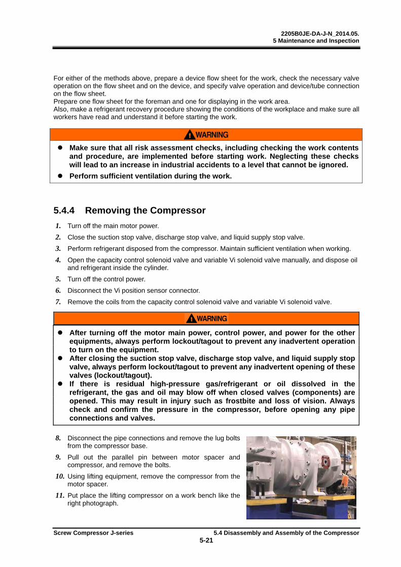
2205B0JE-DA-J-N_2014.05. 5 Maintenance and Inspection
Screw Compressor J-series 5.4 Disassembly and Assembly of the Compressor
5-21
For either of the methods above, prepare a device flow sheet for the work, check the necessary valve operation on the flow sheet and on the device, and specify valve operation and device/tube connection on the flow sheet. Prepare one flow sheet for the foreman and one for displaying in the work area. Also, make a refrigerant recovery procedure showing the conditions of the workplace and make sure all workers have read and understand it before starting the work.
Make sure that all risk assessment checks, including checking the work contents and procedure, are implemented before starting work. Neglecting these checks will lead to an increase in industrial accidents to a level that cannot be ignored.
Perform sufficient ventilation during the work.
5.4.4 Removing the Compressor
1. Turn off the main motor power.
2. Close the suction stop valve, discharge stop valve, and liquid supply stop valve.
3. Perform refrigerant disposed from the compressor. Maintain sufficient ventilation when working.
4. Open the capacity control solenoid valve and variable Vi solenoid valve manually, and dispose oil and refrigerant inside the cylinder.
5. Turn off the control power.
6. Disconnect the Vi position sensor connector.
7. Remove the coils from the capacity control solenoid valve and variable Vi solenoid valve.
After turning off the motor main power, control power, and power for the other equipments, always perform lockout/tagout to prevent any inadvertent operation to turn on the equipment.
After closing the suction stop valve, discharge stop valve, and liquid supply stop valve, always perform lockout/tagout to prevent any inadvertent opening of these valves (lockout/tagout).
If there is residual high-pressure gas/refrigerant or oil dissolved in the refrigerant, the gas and oil may blow off when closed valves (components) are opened. This may result in injury such as frostbite and loss of vision. Always check and confirm the pressure in the compressor, before opening any pipe connections and valves.
8. Disconnect the pipe connections and remove the lug bolts from the compressor base.
9. Pull out the parallel pin between motor spacer and compressor, and remove the bolts.
10. Using lifting equipment, remove the compressor from the motor spacer.
11. Put place the lifting compressor on a work bench like the right photograph.
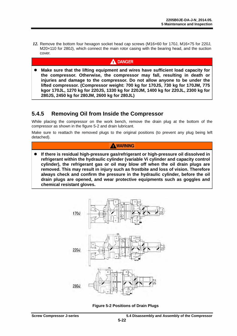
2205B0JE-DA-J-N_2014.05. 5 Maintenance and Inspection
Screw Compressor J-series 5.4 Disassembly and Assembly of the Compressor
5-22
12. Remove the bottom four hexagon socket head cap screws (M16×60 for 170J, M16×75 for 220J, M20×110 for 280J), which connect the main rotor casing with the bearing head, and the suction cover.
Make sure that the lifting equipment and wires have sufficient load capacity for the compressor. Otherwise, the compressor may fall, resulting in death or injuries and damage to the compressor. Do not allow anyone to be under the lifted compressor. (Compressor weight: 700 kg for 170JS, 730 kg for 170JM, 775 kgor 170JL, 1270 kg for 220JS, 1330 kg for 220JM, 1400 kg for 220JL, 2300 kg for 280JS, 2450 kg for 280JM, 2600 kg for 280JL)
5.4.5 Removing Oil from Inside the Compressor While placing the compressor on the work bench, remove the drain plug at the bottom of the compressor as shown in the figure 5-2 and drain lubricant.
Make sure to reattach the removed plugs to the original positions (to prevent any plug being leftdetached).
If there is residual high-pressure gas/refrigerant or high-pressure oil dissolved in refrigerant within the hydraulic cylinder (variable Vi cylinder and capacity control cylinder), the refrigerant gas or oil may blow off when the oil drain plugs are removed. This may result in injury such as frostbite and loss of vision. Therefore always check and confirm the pressure in the hydraulic cylinder, before the oil drain plugs are opened, and wear protective equipments such as goggles and chemical resistant gloves.
Figure 5-2 Positions of Drain Plugs
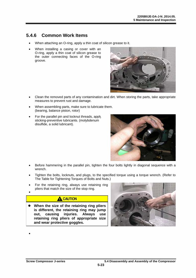
2205B0JE-DA-J-N_2014.05. 5 Maintenance and Inspection
Screw Compressor J-series 5.4 Disassembly and Assembly of the Compressor
5-23
5.4.6 Common Work Items
When attaching an O-ring, apply a thin coat of silicon grease to it.
When installing a casing or cover with anO-ring, apply a thin coat of silicon grease tothe outer connecting faces of the O-ring groove.
Clean the removed parts of any contamination and dirt. When storing the parts, take appropriatemeasures to prevent rust and damage.
When assembling parts, make sure to lubricate them. (bearing, balance piston, rotor)
For the parallel pin and locknut threads, applysticking-preventive lubricants. (molybdenum disulfide, a solid lubricant).
Before hammering in the parallel pin, tighten the four bolts lightly in diagonal sequence with awrench.
Tighten the bolts, locknuts, and plugs, to the specified torque using a torque wrench. (Refer to The Table for Tightening Torques of Bolts and Nuts.)
For the retaining ring, always use retaining ringpliers that match the size of the stop ring.
When the size of the retaining ring pliers is different, the retaining ring may jump out, causing injuries. Always use retaining ring pliers of appropriate size and wear protective goggles.
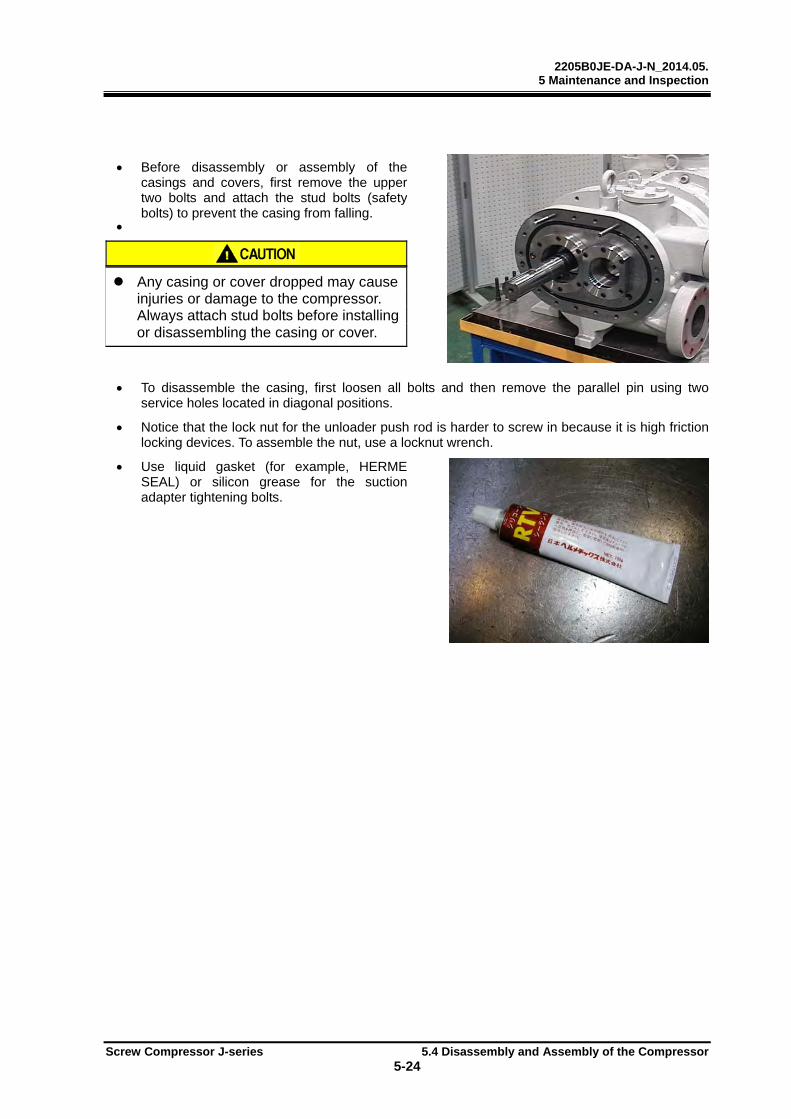
2205B0JE-DA-J-N_2014.05. 5 Maintenance and Inspection
Screw Compressor J-series 5.4 Disassembly and Assembly of the Compressor
5-24
Before disassembly or assembly of thecasings and covers, first remove the uppertwo bolts and attach the stud bolts (safety bolts) to prevent the casing from falling.
Any casing or cover dropped may cause injuries or damage to the compressor. Always attach stud bolts before installing or disassembling the casing or cover.
To disassemble the casing, first loosen all bolts and then remove the parallel pin using two service holes located in diagonal positions.
Notice that the lock nut for the unloader push rod is harder to screw in because it is high frictionlocking devices. To assemble the nut, use a locknut wrench.
Use liquid gasket (for example, HERMESEAL) or silicon grease for the suctionadapter tightening bolts.
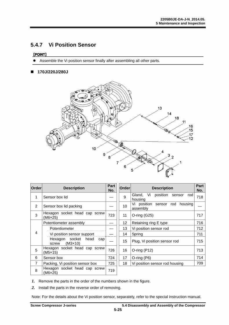
2205B0JE-DA-J-N_2014.05. 5 Maintenance and Inspection
Screw Compressor J-series 5.4 Disassembly and Assembly of the Compressor
5-25
5.4.7 Vi Position Sensor
Assemble the Vi position sensor finally after assembling all other parts.
170J/220J/280J
Order Description Part No.
Order Description Part No.
1 Sensor box lid — 9 Gland, Vi position sensor rod housing
718
2 Sensor box lid packing — 10 Vi position sensor rod housing assembly
—
3 Hexagon socket head cap screw (M6×25)
723 11 O-ring (G25) 717
4
Potentiometer assembly — 12 Retaining ring E type 716
Potentiometer — 13 Vi position sensor rod 712
Vi position sensor support — 14 Spring 711Hexagon socket head cap screw (M3×10)
— 15 Plug, Vi position sensor rod 715
5 Hexagon socket head cap screw (M5×15)
726 16 O-ring (P12) 713
6 Sensor box 724 17 O-ring (P6) 714
7 Packing, Vi position sensor box 725 18 Vi position sensor rod housing 709
8 Hexagon socket head cap screw (M6×25)
719
1. Remove the parts in the order of the numbers shown in the figure.
2. Install the parts in the reverse order of removing.
Note: For the details about the Vi position sensor, separately, refer to the special instruction manual.
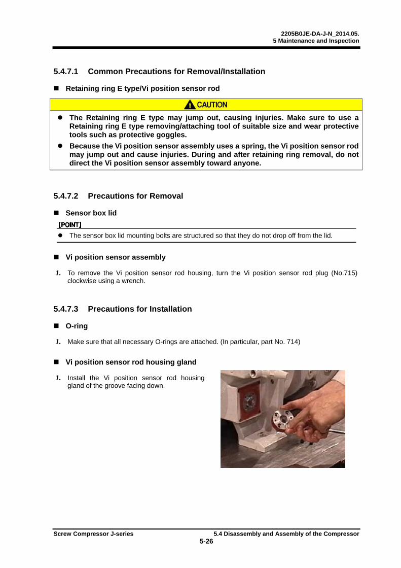
2205B0JE-DA-J-N_2014.05. 5 Maintenance and Inspection
Screw Compressor J-series 5.4 Disassembly and Assembly of the Compressor
5-26
5.4.7.1 Common Precautions for Removal/Installation
Retaining ring E type/Vi position sensor rod
The Retaining ring E type may jump out, causing injuries. Make sure to use a Retaining ring E type removing/attaching tool of suitable size and wear protective tools such as protective goggles.
Because the Vi position sensor assembly uses a spring, the Vi position sensor rod may jump out and cause injuries. During and after retaining ring removal, do not direct the Vi position sensor assembly toward anyone.
5.4.7.2 Precautions for Removal
Sensor box lid
The sensor box lid mounting bolts are structured so that they do not drop off from the lid.
Vi position sensor assembly
1. To remove the Vi position sensor rod housing, turn the Vi position sensor rod plug (No.715) clockwise using a wrench.
5.4.7.3 Precautions for Installation
O-ring
1. Make sure that all necessary O-rings are attached. (In particular, part No. 714)
Vi position sensor rod housing gland
1. Install the Vi position sensor rod housing gland of the groove facing down.

2205B0JE-DA-J-N_2014.05. 5 Maintenance and Inspection
Screw Compressor J-series 5.4 Disassembly and Assembly of the Compressor
5-27
5.4.8 Seal Cover
170J
Order Description Part No.
Order Description Part No.
1 Shaft key 91 8 O-ring (G100) 657
2 Hexagon socket head cap screw (M8×30)
539
Mechanical seal assembly Mating ring
100100-2
3 Seal cover assembly —
4 O-ring (G145) 52-210
Mechanical seal assembly
O-ring 100
100-15 O-ring (G120) 52-1
6 Retaining ring C type internal
(H100) 658 11 Seal cover 51
7 Sleeve, shower flushing 611
1. Remove the parts in the order of numbers shown in the figure.
2. Install the parts in the reverse order of removing.

2205B0JE-DA-J-N_2014.05. 5 Maintenance and Inspection
Screw Compressor J-series 5.4 Disassembly and Assembly of the Compressor
5-28
220J/280J
Order Description Part No.
Order Description Part No.
1 Shaft key 91 7 O-ring (G120/G140) 657
2 Hexagon socket head cap screw (M10×35/ M12×40)
538
Mechanical seal assembly Mating ring
100100-2
3 Seal cover assembly —
4 O-ring (G145/G165) 52-1
9 Mechanical seal assembly O-ring
100100-15
Retaining ring C type internal (H120/ H140)
658
6 Sleeve, shower flushing 611 10 Shaft seal cover 51
1. Remove the parts in the order of numbers shown in the figure.
2. Install the parts in the reverse order of removing.
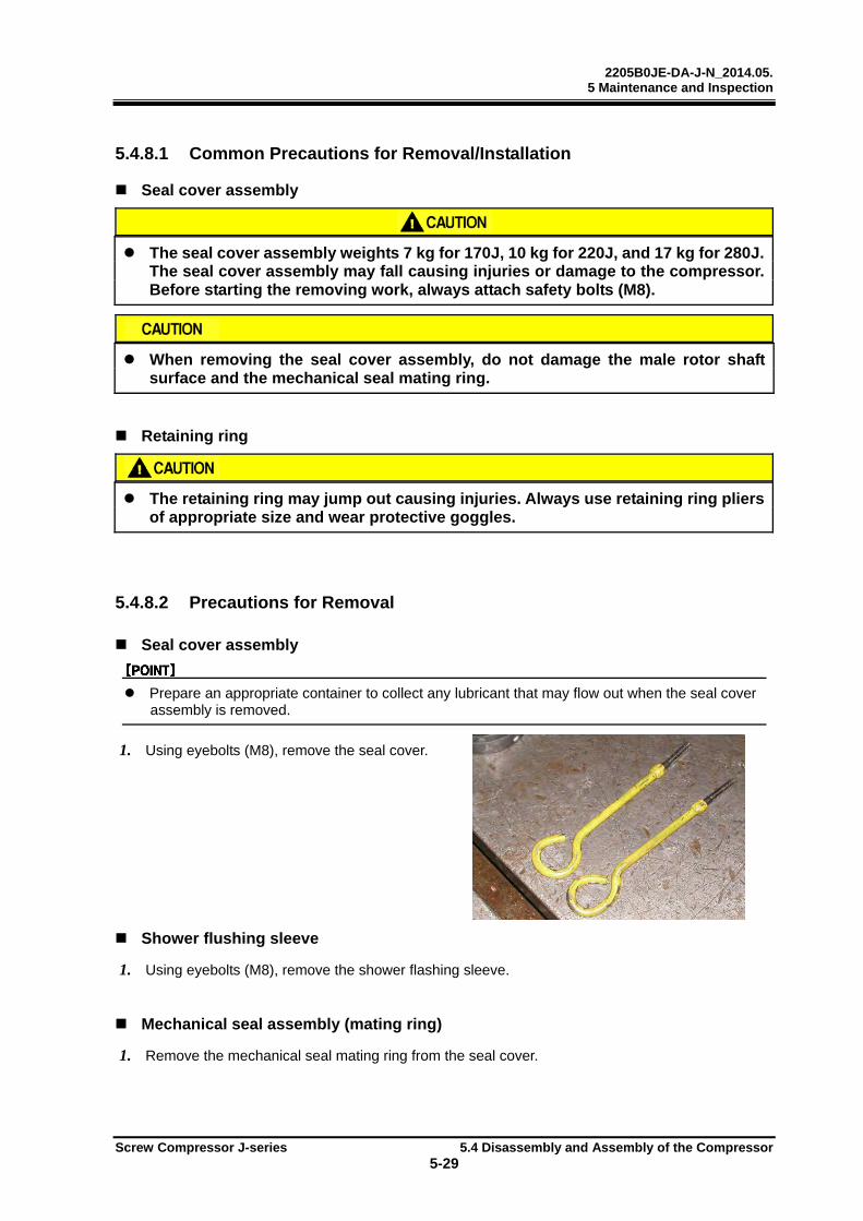
2205B0JE-DA-J-N_2014.05. 5 Maintenance and Inspection
Screw Compressor J-series 5.4 Disassembly and Assembly of the Compressor
5-29
5.4.8.1 Common Precautions for Removal/Installation
Seal cover assembly
The seal cover assembly weights 7 kg for 170J, 10 kg for 220J, and 17 kg for 280J. The seal cover assembly may fall causing injuries or damage to the compressor. Before starting the removing work, always attach safety bolts (M8).
When removing the seal cover assembly, do not damage the male rotor shaft surface and the mechanical seal mating ring.
Retaining ring
The retaining ring may jump out causing injuries. Always use retaining ring pliers of appropriate size and wear protective goggles.
5.4.8.2 Precautions for Removal
Seal cover assembly
Prepare an appropriate container to collect any lubricant that may flow out when the seal cover assembly is removed.
1. Using eyebolts (M8), remove the seal cover.
Shower flushing sleeve
1. Using eyebolts (M8), remove the shower flashing sleeve.
Mechanical seal assembly (mating ring)
1. Remove the mechanical seal mating ring from the seal cover.
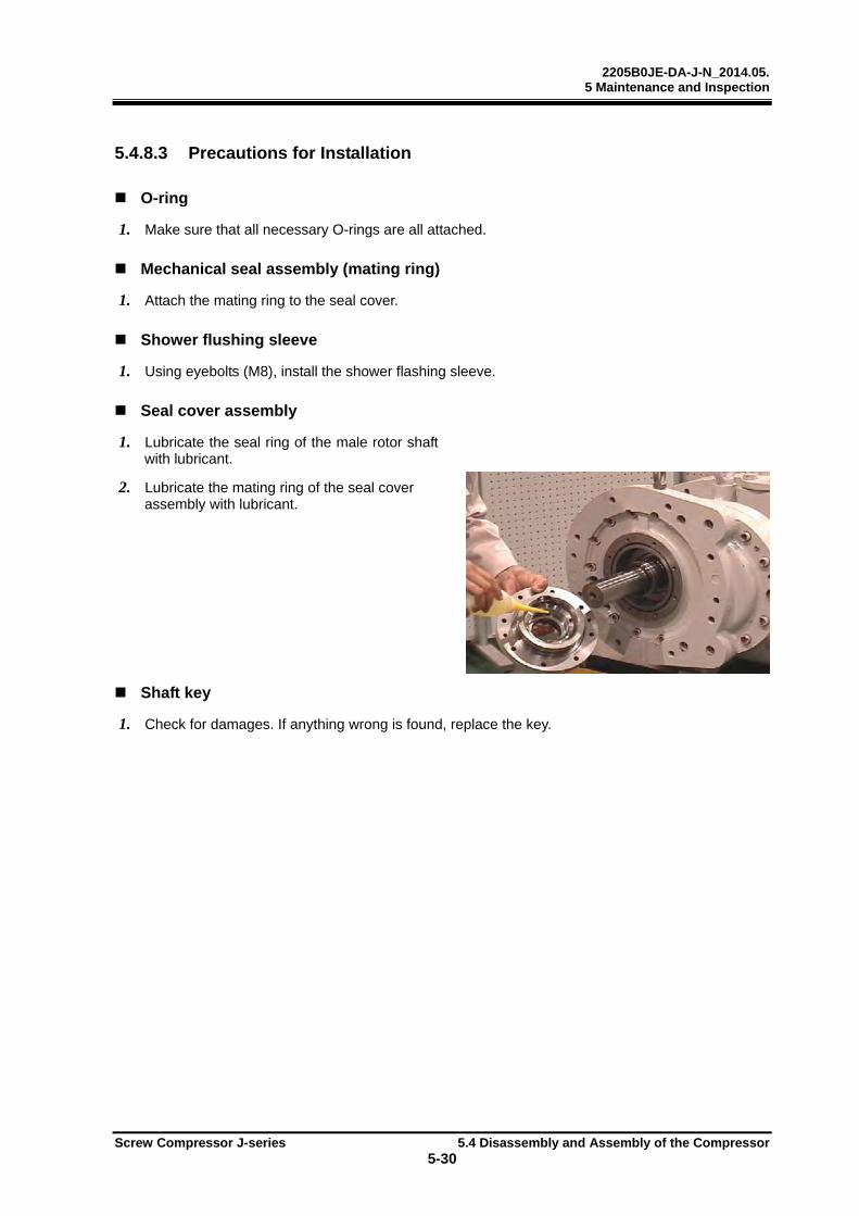
2205B0JE-DA-J-N_2014.05. 5 Maintenance and Inspection
Screw Compressor J-series 5.4 Disassembly and Assembly of the Compressor
5-30
5.4.8.3 Precautions for Installation
O-ring
1. Make sure that all necessary O-rings are all attached.
Mechanical seal assembly (mating ring)
1. Attach the mating ring to the seal cover.
Shower flushing sleeve
1. Using eyebolts (M8), install the shower flashing sleeve.
Seal cover assembly
1. Lubricate the seal ring of the male rotor shaft with lubricant.
2. Lubricate the mating ring of the seal cover assembly with lubricant.
Shaft key
1. Check for damages. If anything wrong is found, replace the key.

2205B0JE-DA-J-N_2014.05. 5 Maintenance and Inspection
Screw Compressor J-series 5.4 Disassembly and Assembly of the Compressor
5-31
5.4.9 Bearing Cover
170J/220J/280J
Order Description Part No.
Order Description Part No.
1 Mechanical seal assembly 100 9 Oil seal 50
Hexagon socket set screw 100-5 10 Retainer for oil seal 48
2 Mechanical seal assembly 100 11
Spring pin (3 dia.×8/3 dia.×10/3 dia.×10)
20
O-ring 100-4
12
Hexagon socket head cap screw (280J: M20×50)
18
3 Mechanical seal assembly 100
Hexagon socket head cap screw (M12×50/M16×60)
18-1
Rotating ring 100-3Hexagon socket head cap screw (M12×70/M16×90)
18-2
4 O-ring (G120/G145/G165) 49 13 Bearing cover 16
5 O-ring (G55/G70/G90) 744 14 Parallel pin (10 dia. ×55/13 dia. ×65/16 dia. ×70)
19
6 Hexagon socket set screw (M6×8) 529 15 O-ring (P300/P375/P480) 17-1
7 Sleeve, oil seal 528 16 O-ring (P14) 17-2
8 Retainer for oil seal — Bush, P14 type O-ring 537
1. Remove the parts in the order of the numbers shown in the figure.
2. Install the parts in the reverse order of removing.

2205B0JE-DA-J-N_2014.05. 5 Maintenance and Inspection
Screw Compressor J-series 5.4 Disassembly and Assembly of the Compressor
5-32
5.4.9.1 Common Precautions for Removal/Installation
Bearing cover
If the lifting equipment and lifting slings in use do not have sufficient loading capacity, the bearing cover may fall causing injuries and damage to the compressor. Before starting the lifting work, always check that the lifting equipment and lifting slings have sufficient loading capacity. Do not allow anyone to be under the lifted bearing cover. (Bearing cover weight: 47 kg for 170J, 74 kg for 220J, 82 kg for 280J)
Do not damage the male rotor shaft surface, when removing/installing the bearing cover.
5.4.9.2 Precautions for Removal
Mechanical seal assembly (rotating ring)
Loosen the hexagon socket set screw for at least more than 5 turns and remove mechanical seal assembly from the male rotor shaft. If the hexagon socket set screw is not turned and loosened for 5 turns or more, the male rotor shaft surface may be damaged.
Oil seal sleeve/retainer for oil seal
Loosen the hexagon socket set screw for at least more than 2 turns and remove the oil seal sleeve from male rotor shaft. If the hexagon socket set screw is not turned and loosened for 2 turns or more, the male rotor shaft surface may be damaged.
1. Loosen the hexagon socket set screw for oil seal sleeve at least 2 turns or more.
2. Attach eyebolts (M8) to the retainer for an oil seal, remove the retainer and oil seal sleeve as an assembly.
3. Using a flat screwdriver and a hammer, remove the oil seal from the retainer.
The spring pin (3 dia. x 8/3 dia. x 10) attached to the bearing cover may not be pulled out during a regular service.

2205B0JE-DA-J-N_2014.05. 5 Maintenance and Inspection
Screw Compressor J-series 5.4 Disassembly and Assembly of the Compressor
5-33
Bearing cover
1. Remove the two upper hexagon socket head cap screws (M12×50, M12×70, and M20×70) and attach safety bolts.
2. Remove the rest of the hexagon socket head cap screws (M12×70, M12×50, and M20×70).
3. To pull out the parallel pins, insert hexagon socket head cap screws (M12 and M20) into the service holes and tighten the hexagon socket head cap screws so that the gap between the bearing cover and the bearing head expands in parallel.
Even though screwing the forcing bolts evenly, when the gap between bearing cover and bearing head does not open parallel and parallel pins are fixed unevenly, use a plastic hammer to adjust the gap evenly.
If the parallel pins are not pulled out, use a slide hammer.
4. Using the lifting equipment, remove the bearing cover.
5.4.9.3 Precautions for Installation
O-ring (P300/P375/P480)
1. After disassembly, replace the existing O-rings with new ones.
Oil seal
1. With the lip of the oil seal facing down, set the oil seal on the retainer for oil seal.
2. Using an appropriate tool such as a plastic block, insert the oil seal fully into the retainer for oil seal by tapping.
Oil seal sleeve/oil seal/retainer for oil seal
1. Lubricate the oil seal sleeve with lubricant.
2. Insert the oil seal sleeve into the retainer for oil seal.
3. Attach eyebolts (M8) to the retainer for oil seal and install both the retainer and the oil seal sleeve as an assembly into the bearing cover.
4. When installing the retainer for oil seal assembly into the bearing cover, face the cutout of retainer upward and align the cutout of retainer to the spring pin on the bearing cover.
Mechanical seal assembly
1. Install the mechanical seal ring by aligning the hexagon socket set screw positions and the drilled holes of the male rotor shaft.
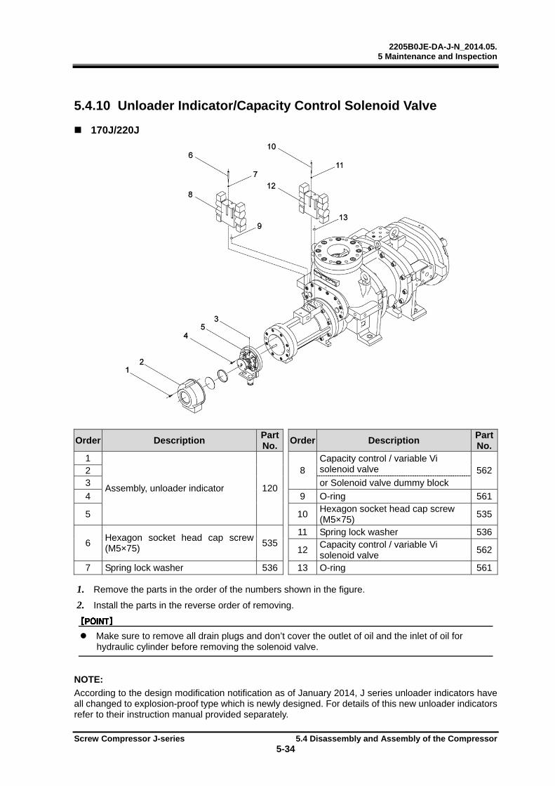
2205B0JE-DA-J-N_2014.05. 5 Maintenance and Inspection
Screw Compressor J-series 5.4 Disassembly and Assembly of the Compressor
5-34
5.4.10 Unloader Indicator/Capacity Control Solenoid Valve
170J/220J
Order Description Part No.
Order Description Part No.
1
Assembly, unloader indicator 120
8 Capacity control / variable Vi solenoid valve 5622
3 or Solenoid valve dummy block
4 9 O-ring 561
5 10 Hexagon socket head cap screw (M5×75)
535
6 Hexagon socket head cap screw (M5×75)
53511 Spring lock washer 536
12 Capacity control / variable Vi solenoid valve
562
7 Spring lock washer 536 13 O-ring 561
1. Remove the parts in the order of the numbers shown in the figure.
2. Install the parts in the reverse order of removing.
Make sure to remove all drain plugs and don’t cover the outlet of oil and the inlet of oil for hydraulic cylinder before removing the solenoid valve.
NOTE:
According to the design modification notification as of January 2014, J series unloader indicators have all changed to explosion-proof type which is newly designed. For details of this new unloader indicators refer to their instruction manual provided separately.
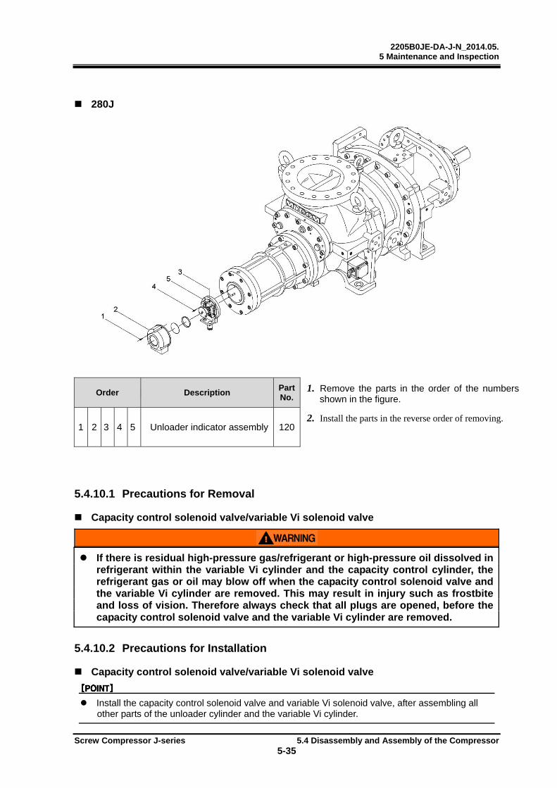
2205B0JE-DA-J-N_2014.05. 5 Maintenance and Inspection
Screw Compressor J-series 5.4 Disassembly and Assembly of the Compressor
5-35
280J
Order Description PartNo.
1. Remove the parts in the order of the numbers shown in the figure.
1 2 3 4 5 Unloader indicator assembly 1202. Install the parts in the reverse order of removing.
5.4.10.1 Precautions for Removal
Capacity control solenoid valve/variable Vi solenoid valve
If there is residual high-pressure gas/refrigerant or high-pressure oil dissolved in refrigerant within the variable Vi cylinder and the capacity control cylinder, the refrigerant gas or oil may blow off when the capacity control solenoid valve and the variable Vi cylinder are removed. This may result in injury such as frostbite and loss of vision. Therefore always check that all plugs are opened, before the capacity control solenoid valve and the variable Vi cylinder are removed.
5.4.10.2 Precautions for Installation
Capacity control solenoid valve/variable Vi solenoid valve
Install the capacity control solenoid valve and variable Vi solenoid valve, after assembling all other parts of the unloader cylinder and the variable Vi cylinder.
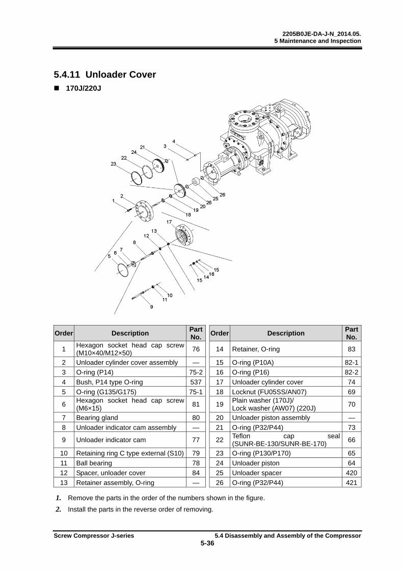
2205B0JE-DA-J-N_2014.05. 5 Maintenance and Inspection
Screw Compressor J-series 5.4 Disassembly and Assembly of the Compressor
5-36
5.4.11 Unloader Cover 170J/220J
Order Description Part No.
Order Description Part No.
1 Hexagon socket head cap screw (M10×40/M12×50)
76 14 Retainer, O-ring 83
2 Unloader cylinder cover assembly — 15 O-ring (P10A) 82-1
3 O-ring (P14) 75-2 16 O-ring (P16) 82-2
4 Bush, P14 type O-ring 537 17 Unloader cylinder cover 74
5 O-ring (G135/G175) 75-1 18 Locknut (FU05SS/AN07) 69
6 Hexagon socket head cap screw (M6×15)
81 19 Plain washer (170J)/ Lock washer (AW07) (220J)
70
7 Bearing gland 80 20 Unloader piston assembly —
8 Unloader indicator cam assembly — 21 O-ring (P32/P44) 73
9 Unloader indicator cam 77 22 Teflon cap seal (SUNR-BE-130/SUNR-BE-170)
66
10 Retaining ring C type external (S10) 79 23 O-ring (P130/P170) 65
11 Ball bearing 78 24 Unloader piston 64
12 Spacer, unloader cover 84 25 Unloader spacer 420
13 Retainer assembly, O-ring — 26 O-ring (P32/P44) 421
1. Remove the parts in the order of the numbers shown in the figure.
2. Install the parts in the reverse order of removing.

2205B0JE-DA-J-N_2014.05. 5 Maintenance and Inspection
Screw Compressor J-series 5.4 Disassembly and Assembly of the Compressor
5-37
280J
Order Description Part No.
Order Description Part No.
1 Hexagon socket head cap screw (M16×60)
76 13 O-ring (P10A) 82-1
2 Unloader cylinder cover assembly — 14 O-ring (P16) 82-2
3 O-ring (G230) (280J) 75 15 Unloader cylinder cover 74
4 Hexagon socket head cap screw (M6×15)
81 16 Locknut (AN09) 69
5 Bearing gland 80 17 Lock washer (AW09) 70
6 Unloader indicator cam assembly — 18 Unloader piston assembly —
7 Unloader indicator cam 77 19 Unloader piston 64
8 Retaining ring C type external (S10) 79 20 O-ring (P225) 65
9 Ball bearing 78 21 Teflon cap seal (SUNR-BE-225) 66
10 Spacer, unloader cover 84 22 O-ring (P58) 73
11 Retainer assembly, O-ring — 23 Unloader spacer 420
12 Retainer, O-ring 83 24 O-ring (P58) 421
1. Remove the parts in the order of the numbers shown in the figure.
2. Install the parts in the reverse order of removing.

2205B0JE-DA-J-N_2014.05. 5 Maintenance and Inspection
Screw Compressor J-series 5.4 Disassembly and Assembly of the Compressor
5-38
5.4.11.1 Common Precautions for Removal/Installation
Unloader cylinder cover assembly
Pull out /Install the unloader cylinder cover assembly horizontally. The unloader indicator cam may be damaged if handled inappropriately.
Retaining ring
The retaining ring may jump out, causing injuries. Always use retaining ring pliers of appropriate size and wear protective goggles.
Unloader piston
The 170JS, 170JM, 220JS, 220JM, 280JS, and 280JM have an unloader spacer installed at the back of unloader piston. Therefore, remove the unloader spacer form the unloader push rod after removing the unloader piston, when disassembling the 170JS, 170JM, 220JS, 220JM, 280JS, and 280JM.
Therefore, install the unloader spacer to the unloader push rod before installing the unloader piston, when assembling the 170JS, 170JM, 220JS, 220JM, 280JS, and 280JM.
5.4.11.2 Precautions for Removal
Unloader cylinder cover assembly
The unloader indicator cam is assembled in the unloader cylinder cover assembly. The unloader indicator cam is fitted on the internal surface of the unloader slide valve push rod and rotated by the pin of the push rod as guide.
1. Insert hexagon socket head cap screws (M10, for 170J) or eye bolts (M8, for 220J/280J) in the service holes and tighten the screws evenly to expand the gap between the flange faces of unloader cylinder and unloader cylinder cover.
2. Hold the hexagon socket head cap screws (M10, for 170J) or eye bolts (M8, for 220J/280J), pull out the unloader cylinder cover horizontally and remove.
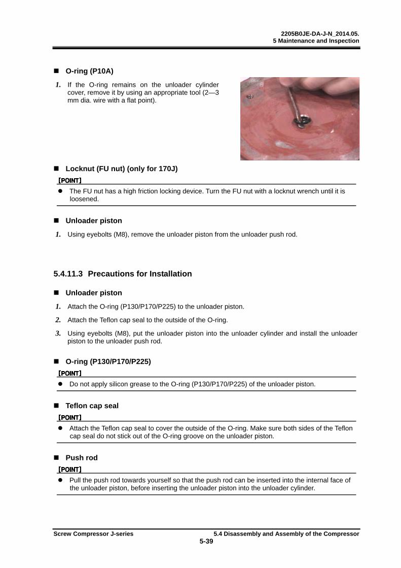
2205B0JE-DA-J-N_2014.05. 5 Maintenance and Inspection
Screw Compressor J-series 5.4 Disassembly and Assembly of the Compressor
5-39
O-ring (P10A)
1. If the O-ring remains on the unloader cylinder cover, remove it by using an appropriate tool (2—3 mm dia. wire with a flat point).
Locknut (FU nut) (only for 170J)
The FU nut has a high friction locking device. Turn the FU nut with a locknut wrench until it is loosened.
Unloader piston
1. Using eyebolts (M8), remove the unloader piston from the unloader push rod.
5.4.11.3 Precautions for Installation
Unloader piston
1. Attach the O-ring (P130/P170/P225) to the unloader piston.
2. Attach the Teflon cap seal to the outside of the O-ring.
3. Using eyebolts (M8), put the unloader piston into the unloader cylinder and install the unloader piston to the unloader push rod.
O-ring (P130/P170/P225)
Do not apply silicon grease to the O-ring (P130/P170/P225) of the unloader piston.
Teflon cap seal
Attach the Teflon cap seal to cover the outside of the O-ring. Make sure both sides of the Teflon cap seal do not stick out of the O-ring groove on the unloader piston.
Push rod
Pull the push rod towards yourself so that the push rod can be inserted into the internal face of the unloader piston, before inserting the unloader piston into the unloader cylinder.

2205B0JE-DA-J-N_2014.05. 5 Maintenance and Inspection
Screw Compressor J-series 5.4 Disassembly and Assembly of the Compressor
5-40
O-ring (P10A)
1. Assemble the O-ring (P10A) to the inside of the O-ring retainer in advance.
O-ring retainer
1. Attach two O-rings (P10A) to the inner face of the O-ring retainer and one O-ring (P16) to the outer face, and install the O-ring retainer to the unloader cylinder cover.
Unloader cylinder cover spacer
1. Install the unloader cylinder cover spacer to the unloader cylinder cover with the flat face to the atmosphere side.
Unloader indicator cam assembly
1. Install the ball bearing to the cam shaft, with the surface with stamped letters (mfg codes) of the ball bearing facing the suction cover side.
2. Attach the retaining ring C type external (S10).
3. Install the unloader indicator cam with the ball bearing to the unloader cover.
Bearing gland
1. Install the bearing gland so that it contacts the ball bearing of the unloader indicator cam.
Locknut (FU nut) (only for 170J)
The FU nut has a high friction locking device. Turn the FU nut with a locknut wrench when tightening the FU nut.

2205B0JE-DA-J-N_2014.05. 5 Maintenance and Inspection
Screw Compressor J-series 5.4 Disassembly and Assembly of the Compressor
5-41
Unloader cylinder cover assembly
1. The unloader indicator cam groove opening must face upwards, when installing into the unloader slide valve push rod pin.
2. Install the unloader assembly to the unloader cylinder with the diagonal service holes of the unloader cover horizontal, and with one of the three tap holes for unloader indicator assembly above the horizontal service holes.
3. Check that the cam rotates smoothly by moving the unloader cover assembly back and forth horizontally.

2205B0JE-DA-J-N_2014.05. 5 Maintenance and Inspection
Screw Compressor J-series 5.4 Disassembly and Assembly of the Compressor
5-42
5.4.12 Unloader Cylinder
170J/220J/280J
Order Description Part No.
Order Description Part No.
1 Hexagon socket head cap screw (M12×70/M16×90/M20×110)
61 4 O-ring (G135/G175/G230) 298
Hexagon socket head cap screw (M12×110/ M16×140/ M20×170)
62 5 Back-up ring for O-ring (SUN-2BP 32/ SUN-2BP 44/ SUN-2BP 58)
325-2
2 Unloader cylinder assembly — 6 O-ring (P32/P44/P58) 325-1
3 Partition plate, unloader cylinder 297 7 Unloader cylinder 60
1. Remove the parts in the order of the numbers shown in the figure.
2. Install the parts in the reverse order of removing.
2205B0JE-DA-J-N_2014.05. 5 Maintenance and Inspection
Screw Compressor J-series 5.4 Disassembly and Assembly of the Compressor
5-43
5.4.12.1 Common Precautions for Removal/Installation
Unloader cylinder assembly
If the lifting equipment and lifting slings in use do not have sufficient loading capacity, the unloader cylinder assembly may fall causing injuries and damage to the compressor. Before starting the lifting work, always check that the lifting equipment and lifting slings have sufficient loading capacity. Do not allow anyone to be under the lifted unloader cylinder assembly. (Unloader cylinder assembly weight: 30 kg for 170J, 60 kg for 220J, 90 kg for 280J)
5.4.12.2 Precautions for Removal
Unloader cylinder assembly
1. Remove the plastic caps from the eyebolt holes and service holes.
2. Attach eyebolt (M12) in eyebolt hole.
3. Remove the two upper hexagon socket head cap screws (M12×70/M16×90/M20×110) and attach stud bolts for safety.
4. Remove the hexagon socket head cap screws (M12×110/ M16×140/ M20×170).
5. Insert the hexagon socket head cap screws (M12) into the service holes and tighten the hexagon socket head cap screws evenly.
6. After the fitted part of the unloader cylinder and balance piston cover is separated, pull the unloader cylinder assembly horizontally towards yourself to remove the unloader cylinder assembly from the unloader slide valve push rod.
7. Lift and carry the unloader cylinder with lifting equipment by using the attached eyebolt (M12) on the unloader cylinder.
Push the unloader slide valve push rod into the inner part of unloader cylinder using eyebolts (M8) attached to the unloader piston, before removing the unloader cylinder.
Pull the unloader cylinder straight and horizontally not to damage the unloader slide valve push rod.
Unloader cylinder partition plate
1. Using eyebolts (M8), remove the unloader cylinder partition plate.
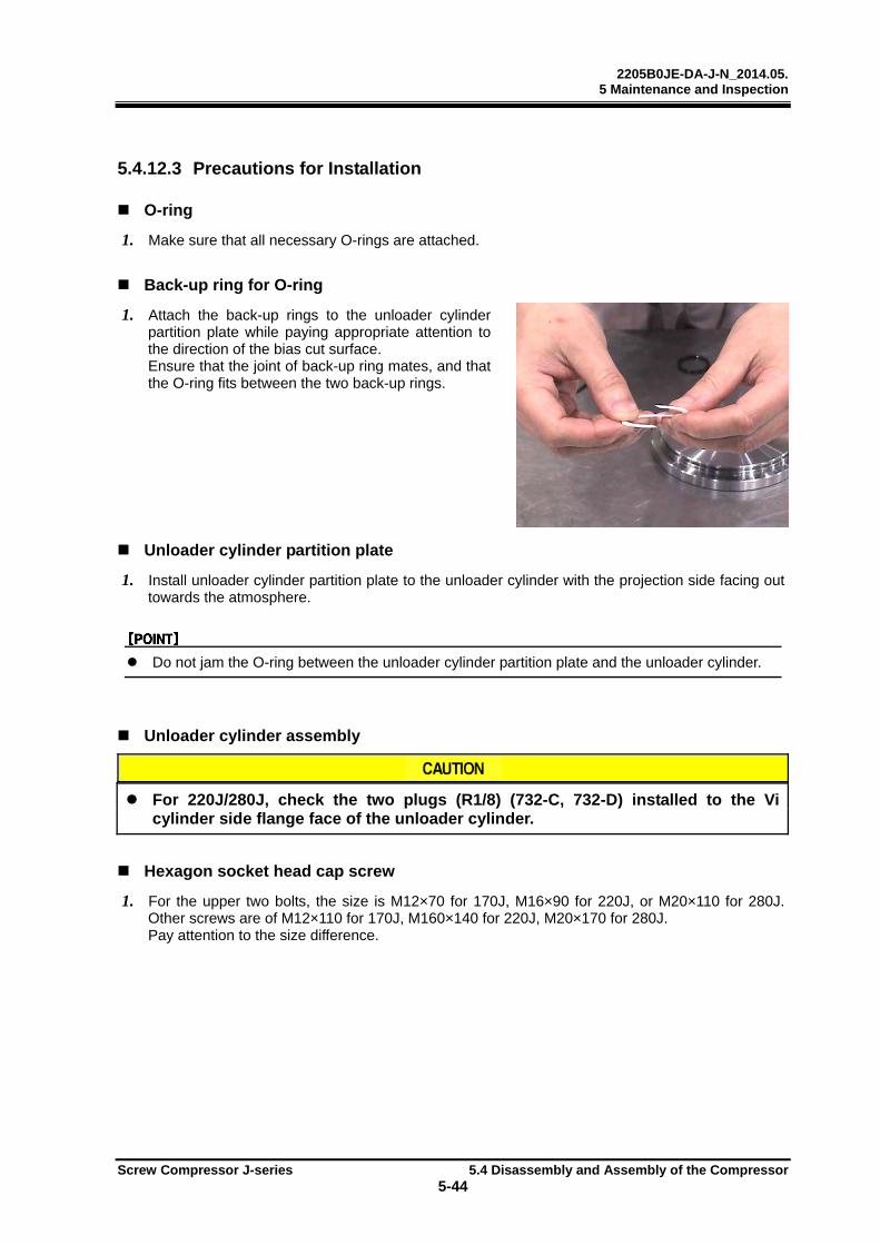
2205B0JE-DA-J-N_2014.05. 5 Maintenance and Inspection
Screw Compressor J-series 5.4 Disassembly and Assembly of the Compressor
5-44
5.4.12.3 Precautions for Installation
O-ring
1. Make sure that all necessary O-rings are attached.
Back-up ring for O-ring
1. Attach the back-up rings to the unloader cylinder partition plate while paying appropriate attention to the direction of the bias cut surface. Ensure that the joint of back-up ring mates, and that the O-ring fits between the two back-up rings.
Unloader cylinder partition plate
1. Install unloader cylinder partition plate to the unloader cylinder with the projection side facing out towards the atmosphere.
Do not jam the O-ring between the unloader cylinder partition plate and the unloader cylinder.
Unloader cylinder assembly
For 220J/280J, check the two plugs (R1/8) (732-C, 732-D) installed to the Vi cylinder side flange face of the unloader cylinder.
Hexagon socket head cap screw
1. For the upper two bolts, the size is M12×70 for 170J, M16×90 for 220J, or M20×110 for 280J. Other screws are of M12×110 for 170J, M160×140 for 220J, M20×170 for 280J. Pay attention to the size difference.
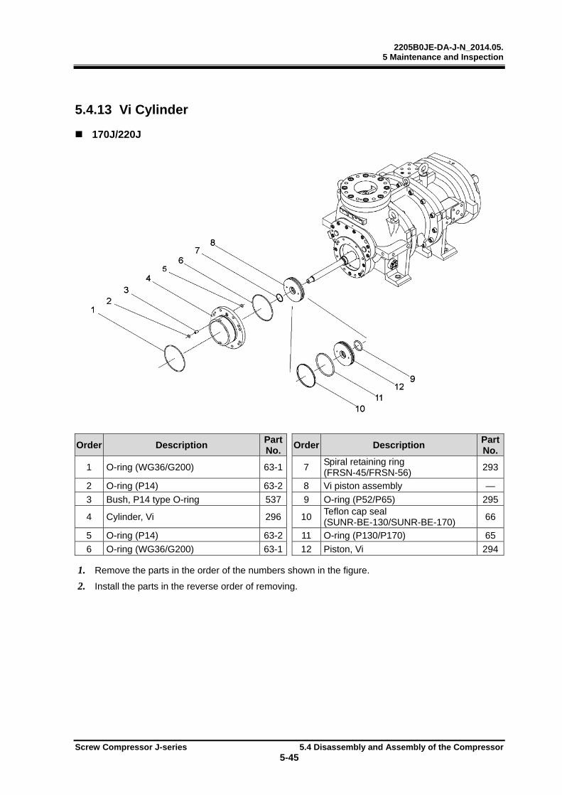
2205B0JE-DA-J-N_2014.05. 5 Maintenance and Inspection
Screw Compressor J-series 5.4 Disassembly and Assembly of the Compressor
5-45
5.4.13 Vi Cylinder
170J/220J
Order Description Part No.
Order Description Part No.
1 O-ring (WG36/G200) 63-1 7 Spiral retaining ring (FRSN-45/FRSN-56)
293
2 O-ring (P14) 63-2 8 Vi piston assembly —
3 Bush, P14 type O-ring 537 9 O-ring (P52/P65) 295
4 Cylinder, Vi 296 10 Teflon cap seal (SUNR-BE-130/SUNR-BE-170)
66
5 O-ring (P14) 63-2 11 O-ring (P130/P170) 65
6 O-ring (WG36/G200) 63-1 12 Piston, Vi 294
1. Remove the parts in the order of the numbers shown in the figure.
2. Install the parts in the reverse order of removing.

2205B0JE-DA-J-N_2014.05. 5 Maintenance and Inspection
Screw Compressor J-series 5.4 Disassembly and Assembly of the Compressor
5-46
280J
Order Description Part No.
Order Description Part No.
1 O-ring (G260) 63 6 O-ring (P85) 295
2 Cylinder, Vi 296 7 Piston, Vi 294
3 O-ring (G260) 63 8 O-ring (P225) 65
4 Spiral retaining ring (FRSN-75) 293 9 Teflon cap seal (SUNR-BE-225) 66
5 Vi piston assembly — — — —
1. Remove the parts in the order of the numbers shown in the figure.
2. Install the parts in the reverse order of removing.
2205B0JE-DA-J-N_2014.05. 5 Maintenance and Inspection
Screw Compressor J-series 5.4 Disassembly and Assembly of the Compressor
5-47
5.4.13.1 Common Precautions for Removal/Installation
Spiral retaining ring
Do not extend the spiral retaining ring excessively in the circumferential direction.
It may cause injuries if extended excessively in the circumferential direction.
5.4.13.2 Precautions for Removal
Vi cylinder
1. Attach the hexagon socket head cap screws (M12 for 170J, M8 for 220J/280J) into the service holes of the Vi cylinder and tighten them evenly to separate the Vi cylinder from the balance piston cover in parallel.
2. After the O-ring part of the Vi cylinder is pulled out, remove the Vi cylinder from the Vi piston by holding the hexagon socket head cap screws (M12 for 170J, M8 for 220J/280J) used as service bolts.
Spiral retaining ring
Do not attempt to extend the spiral retaining ring excessively in the axis direction. The ring will be distorted and can’t reuse it.
Vi piston assembly
1. Using eyebolts, remove the Vi piston assembly from the Vi push rod.
5.4.13.3 Precautions for Installation
Spiral retaining ring
If the spiral retaining ring is distorted, replace it with new one.
O-ring (P130/P170/P225)
Do not apply silicon grease to the O-ring (P130/P170/P225) of the Vi piston.
Teflon cap seal
Attach the Teflon cap seal to cover the outside of the O-ring. Make sure both sides of the Teflon cap seal do not stick out of the O-ring groove on the unloader piston.
Vi cylinder
1. Lubricate the inner face of Vi cylinder with lubricant.
2. Install the Vi cylinder to the Vi piston and push the Vi cylinder into the balance piston cover.
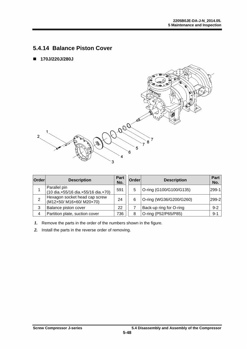
2205B0JE-DA-J-N_2014.05. 5 Maintenance and Inspection
Screw Compressor J-series 5.4 Disassembly and Assembly of the Compressor
5-48
5.4.14 Balance Piston Cover
170J/220J/280J
Order Description Part No.
Order Description Part No.
1 Parallel pin (10 dia.×55/16 dia.×55/16 dia.×70)
591 5 O-ring (G100/G100/G135) 299-1
2 Hexagon socket head cap screw (M12×50/ M16×60/ M20×70)
24 6 O-ring (WG36/G200/G260) 299-2
3 Balance piston cover 22 7 Back-up ring for O-ring 9-2
4 Partition plate, suction cover 736 8 O-ring (P52/P65/P85) 9-1
1. Remove the parts in the order of the numbers shown in the figure.
2. Install the parts in the reverse order of removing.
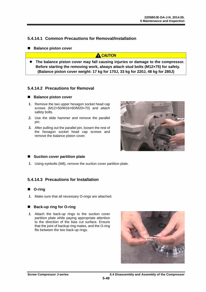
2205B0JE-DA-J-N_2014.05. 5 Maintenance and Inspection
Screw Compressor J-series 5.4 Disassembly and Assembly of the Compressor
5-49
5.4.14.1 Common Precautions for Removal/Installation
Balance piston cover
The balance piston cover may fall causing injuries or damage to the compressor.
Before starting the removing work, always attach stud bolts (M12×75) for safety. (Balance piston cover weight: 17 kg for 170J, 33 kg for 220J, 48 kg for 280J)
5.4.14.2 Precautions for Removal
Balance piston cover
1. Remove the two upper hexagon socket head cap screws (M12×50/M16×60/M20×70) and attach safety bolts.
2. Use the slide hammer and remove the parallel pin.
3. After pulling out the parallel pin, loosen the rest of the hexagon socket head cap screws and remove the balance piston cover.
Suction cover partition plate
1. Using eyebolts (M8), remove the suction cover partition plate.
5.4.14.3 Precautions for Installation
O-ring
1. Make sure that all necessary O-rings are attached.
Back-up ring for O-ring
1. Attach the back-up rings to the suction cover partition plate while paying appropriate attention to the direction of the bias cut surface. Ensure that the joint of backup ring mates, and the O-ring fits between the two back-up rings.
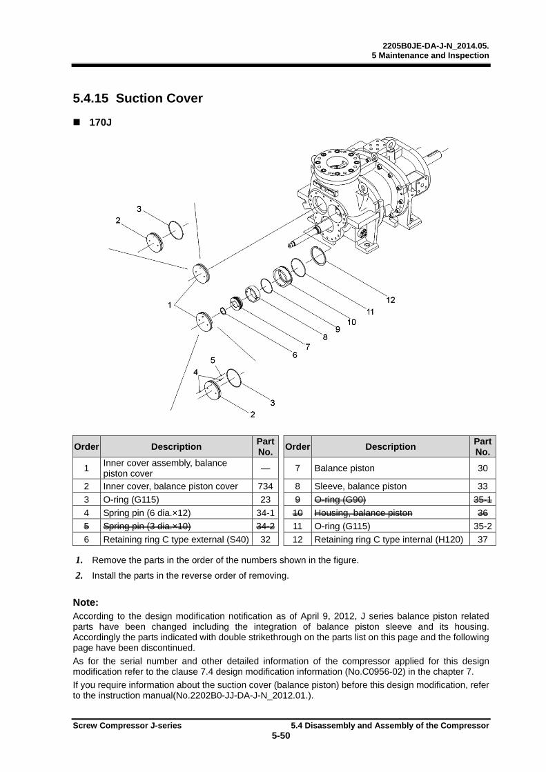
2205B0JE-DA-J-N_2014.05. 5 Maintenance and Inspection
Screw Compressor J-series 5.4 Disassembly and Assembly of the Compressor
5-50
5.4.15 Suction Cover
170J
Order Description Part No.
Order Description Part No.
1 Inner cover assembly, balance piston cover
— 7 Balance piston 30
2 Inner cover, balance piston cover 734 8 Sleeve, balance piston 33
3 O-ring (G115) 23 9 O-ring (G90) 35-1
4 Spring pin (6 dia.×12) 34-1 10 Housing, balance piston 36
5 Spring pin (3 dia.×10) 34-2 11 O-ring (G115) 35-2
6 Retaining ring C type external (S40) 32 12 Retaining ring C type internal (H120) 37
1. Remove the parts in the order of the numbers shown in the figure.
2. Install the parts in the reverse order of removing.
Note: According to the design modification notification as of April 9, 2012, J series balance piston related parts have been changed including the integration of balance piston sleeve and its housing. Accordingly the parts indicated with double strikethrough on the parts list on this page and the following page have been discontinued.
As for the serial number and other detailed information of the compressor applied for this design modification refer to the clause 7.4 design modification information (No.C0956-02) in the chapter 7.
If you require information about the suction cover (balance piston) before this design modification, refer to the instruction manual(No.2202B0-JJ-DA-J-N_2012.01.).

2205B0JE-DA-J-N_2014.05. 5 Maintenance and Inspection
Screw Compressor J-series 5.4 Disassembly and Assembly of the Compressor
5-51
220J/280J
Order Description Part No.
Order Description Part No.
1 Inner cover M assembly, balance piston cover
— 9 Sleeve, balance piston 33
2 Inner cover M, balance piston cover 734-1 10 O-ring (P120/G150) 35-1
3 O-ring (G150/G190) 23-1 11 Housing, balance piston 36
4 Spring pin (6 dia.×12) 34 12 O-ring (G150/G190) 35-2
5 Spring pin (6 dia.×12) 34 13 Inner cover F assembly, balance piston cover
—
6 Spring pin (6 dia.×12) 34 14 Inner cover F, balance piston cover 734-2
7 Retaining ring C type external
(S65/S80) 32 15 O-ring (G115/G150) 23-2
8 Balance piston 30 16 Retaining ring C type internal (H120/None)
37
1. Remove the parts in the order of the numbers shown in the figure.
2. Install the parts in the reverse order of removing.
2205B0JE-DA-J-N_2014.05. 5 Maintenance and Inspection
Screw Compressor J-series 5.4 Disassembly and Assembly of the Compressor
5-52
5.4.15.1 Common Precautions for Removal/Installation
Retaining ring
The retaining ring may jump out, causing injuries. Always use retaining ring pliers
of appropriate size and wear protective goggles.
5.4.15.2 Preparation for Suction Adapter Removal
1. Loosen the hexagon socket head cap screw (No. 493: M20×50 for 170J, M22×60 for 220J) while the suction cover and the main rotor casing are assembled, because it is difficult to hold by hand the suction cover separately while loosening the hexagon socket head cap screw.
Preparation for suction adapter removal is not required for 280J.
5.4.15.3 Precautions for Removal
Balance piston cover inner cover
1. Using eyebolts (M8), remove the balance piston cover inner cover.
For 170J, the balance piston cover inner covers on the male rotor side and the female rotor side are the same. But that on the male rotor side is attached with the spring pins. It is not necessary to remove these spring pins from the balance piston cover inner cover.
Balance piston
1. Using eyebolts (M8), remove the balance piston with the balance piston sleeve.
Balance piston sleeve
1. Using eyebolts (M8), remove the balance piston sleeve.
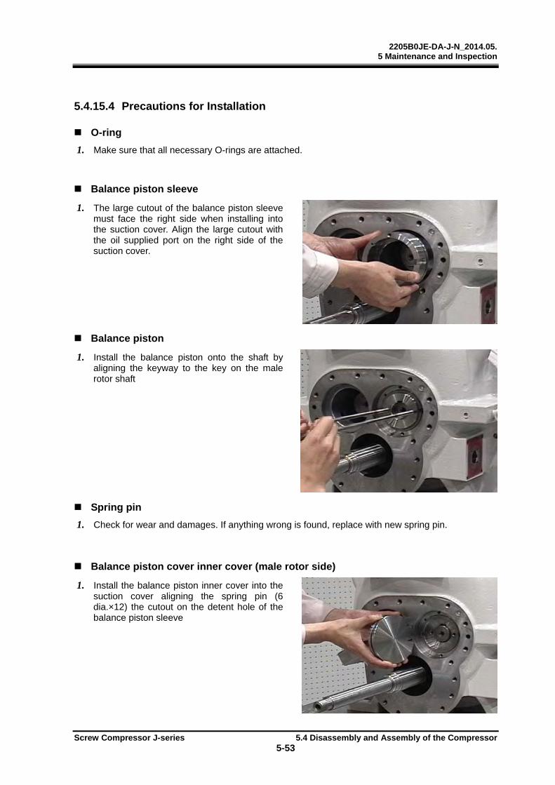
2205B0JE-DA-J-N_2014.05. 5 Maintenance and Inspection
Screw Compressor J-series 5.4 Disassembly and Assembly of the Compressor
5-53
5.4.15.4 Precautions for Installation
O-ring
1. Make sure that all necessary O-rings are attached.
Balance piston sleeve
1. The large cutout of the balance piston sleeve must face the right side when installing into the suction cover. Align the large cutout with the oil supplied port on the right side of the suction cover.
Balance piston
1. Install the balance piston onto the shaft by aligning the keyway to the key on the male rotor shaft
Spring pin
1. Check for wear and damages. If anything wrong is found, replace with new spring pin.
Balance piston cover inner cover (male rotor side)
1. Install the balance piston inner cover into the suction cover aligning the spring pin (6 dia.×12) the cutout on the detent hole of the balance piston sleeve
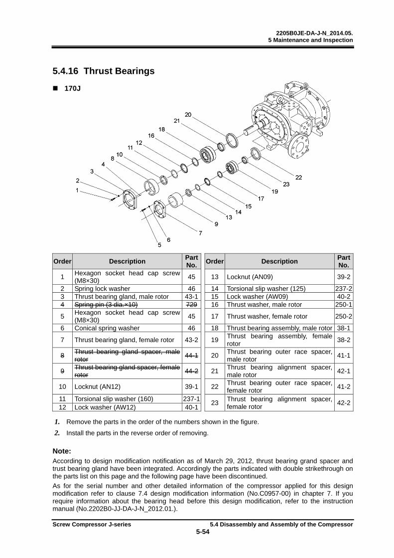
2205B0JE-DA-J-N_2014.05. 5 Maintenance and Inspection
Screw Compressor J-series 5.4 Disassembly and Assembly of the Compressor
5-54
5.4.16 Thrust Bearings
170J
Order Description Part No.
Order Description Part No.
1 Hexagon socket head cap screw (M8×30)
45 13 Locknut (AN09) 39-2
2 Spring lock washer 46 14 Torsional slip washer (125) 237-23 Thrust bearing gland, male rotor 43-1 15 Lock washer (AW09) 40-24 Spring pin (3 dia.×10) 729 16 Thrust washer, male rotor 250-1
5 Hexagon socket head cap screw (M8×30)
45 17 Thrust washer, female rotor 250-2
6 Conical spring washer 46 18 Thrust bearing assembly, male rotor 38-1
7 Thrust bearing gland, female rotor 43-2 19 Thrust bearing assembly, female rotor
38-2
8 Thrust bearing gland spacer, male rotor
44-1 20 Thrust bearing outer race spacer, male rotor
41-1
9 Thrust bearing gland spacer, female rotor
44-2 21 Thrust bearing alignment spacer, male rotor
42-1
10 Locknut (AN12) 39-1 22 Thrust bearing outer race spacer, female rotor
41-2
11 Torsional slip washer (160) 237-123
Thrust bearing alignment spacer, female rotor
42-212 Lock washer (AW12) 40-1
1. Remove the parts in the order of the numbers shown in the figure.
2. Install the parts in the reverse order of removing.
Note: According to design modification notification as of March 29, 2012, thrust bearing grand spacer and trust bearing gland have been integrated. Accordingly the parts indicated with double strikethrough on the parts list on this page and the following page have been discontinued.
As for the serial number and other detailed information of the compressor applied for this design modification refer to clause 7.4 design modification information (No.C0957-00) in chapter 7. If you require information about the bearing head before this design modification, refer to the instruction manual (No.2202B0-JJ-DA-J-N_2012.01.).
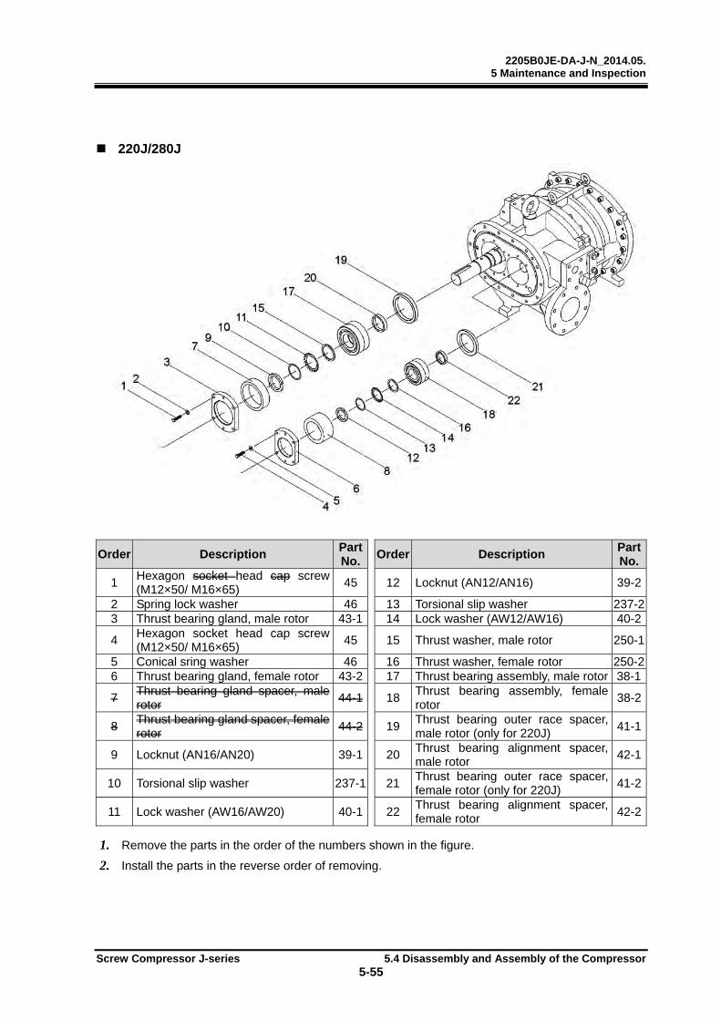
2205B0JE-DA-J-N_2014.05. 5 Maintenance and Inspection
Screw Compressor J-series 5.4 Disassembly and Assembly of the Compressor
5-55
220J/280J
Order Description Part No.
Order Description Part No.
1 Hexagon socket head cap screw (M12×50/ M16×65)
45 12 Locknut (AN12/AN16) 39-2
2 Spring lock washer 46 13 Torsional slip washer 237-23 Thrust bearing gland, male rotor 43-1 14 Lock washer (AW12/AW16) 40-2
4 Hexagon socket head cap screw (M12×50/ M16×65)
45 15 Thrust washer, male rotor 250-1
5 Conical sring washer 46 16 Thrust washer, female rotor 250-26 Thrust bearing gland, female rotor 43-2 17 Thrust bearing assembly, male rotor 38-1
7 Thrust bearing gland spacer, male rotor
44-1 18 Thrust bearing assembly, female rotor
38-2
8 Thrust bearing gland spacer, female rotor
44-2 19 Thrust bearing outer race spacer, male rotor (only for 220J)
41-1
9 Locknut (AN16/AN20) 39-1 20 Thrust bearing alignment spacer, male rotor
42-1
10 Torsional slip washer 237-1 21 Thrust bearing outer race spacer, female rotor (only for 220J)
41-2
11 Lock washer (AW16/AW20) 40-1 22 Thrust bearing alignment spacer, female rotor
42-2
1. Remove the parts in the order of the numbers shown in the figure.
2. Install the parts in the reverse order of removing.
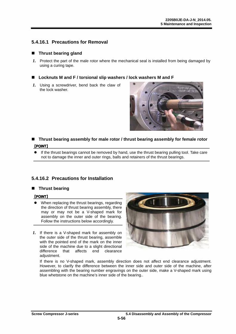
2205B0JE-DA-J-N_2014.05. 5 Maintenance and Inspection
Screw Compressor J-series 5.4 Disassembly and Assembly of the Compressor
5-56
5.4.16.1 Precautions for Removal
Thrust bearing gland
1. Protect the part of the male rotor where the mechanical seal is installed from being damaged by using a curing tape.
Locknuts M and F / torsional slip washers / lock washers M and F
1. Using a screwdriver, bend back the claw of the lock washer.
Thrust bearing assembly for male rotor / thrust bearing assembly for female rotor
If the thrust bearings cannot be removed by hand, use the thrust bearing pulling tool. Take care not to damage the inner and outer rings, balls and retainers of the thrust bearings.
5.4.16.2 Precautions for Installation
Thrust bearing
When replacing the thrust bearings, regarding the direction of thrust bearing assembly, there may or may not be a V-shaped mark for assembly on the outer side of the bearing. Follow the instructions below accordingly.
1. If there is a V-shaped mark for assembly on the outer side of the thrust bearing, assemble with the pointed end of the mark on the inner side of the machine due to a slight directional difference that affects end clearance adjustment.
If there is no V-shaped mark, assembly direction does not affect end clearance adjustment. However, to clarify the difference between the inner side and outer side of the machine, afterassembling with the bearing number engravings on the outer side, make a V-shaped mark using blue whetstone on the machine’s inner side of the bearing..
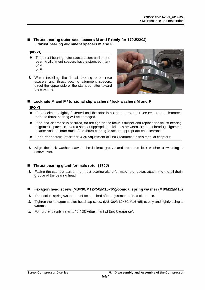
2205B0JE-DA-J-N_2014.05. 5 Maintenance and Inspection
Screw Compressor J-series 5.4 Disassembly and Assembly of the Compressor
5-57
Thrust bearing outer race spacers M and F (only for 170J/220J) / thrust bearing alignment spacers M and F
The thrust bearing outer race spacers and thrust bearing alignment spacers have a stamped mark of M or F.
1. When installing the thrust bearing outer race spacers and thrust bearing alignment spacers, direct the upper side of the stamped letter toward the machine.
Locknuts M and F / torsional slip washers / lock washers M and F
If the locknut is tightly fastened and the rotor is not able to rotate, it secures no end clearance and the thrust bearing will be damaged.
If no end clearance is secured, do not tighten the locknut further and replace the thrust bearing alignment spacer or insert a shim of appropriate thickness between the thrust bearing alignment spacer and the inner race of the thrust bearing to secure appropriate end clearance.
For further details, refer to “5.4.20 Adjustment of End Clearance” in this manual chapter 5.
1. Align the lock washer claw to the locknut groove and bend the lock washer claw using a screwdriver.
Thrust bearing gland for male rotor (170J)
1. Facing the cast out part of the thrust bearing gland for male rotor down, attach it to the oil drain groove of the bearing head.
Hexagon head screw (M8×30/M12×50/M16×65)/conical spring washer (M8/M12/M16)
1. The conical spring washer must be attached after adjustment of end clearance.
2. Tighten the hexagon socket head cap screw (M8×30/M12×50/M16×65) evenly and lightly using a wrench.
3. For further details, refer to "5.4.20 Adjustment of End Clearance".
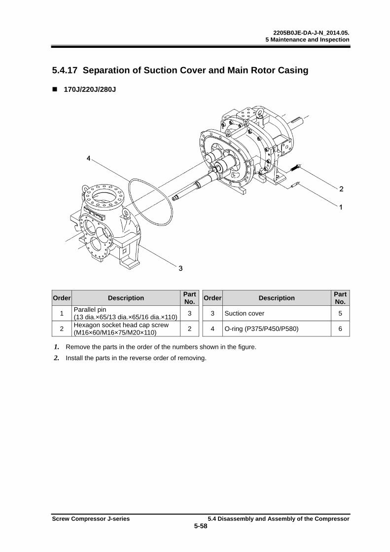
2205B0JE-DA-J-N_2014.05. 5 Maintenance and Inspection
Screw Compressor J-series 5.4 Disassembly and Assembly of the Compressor
5-58
5.4.17 Separation of Suction Cover and Main Rotor Casing
170J/220J/280J
Order Description Part No.
Order Description Part No.
1 Parallel pin (13 dia.×65/13 dia.×65/16 dia.×110)
3 3 Suction cover 5
2 Hexagon socket head cap screw (M16×60/M16×75/M20×110)
2 4 O-ring (P375/P450/P580) 6
1. Remove the parts in the order of the numbers shown in the figure.
2. Install the parts in the reverse order of removing.
2205B0JE-DA-J-N_2014.05. 5 Maintenance and Inspection
Screw Compressor J-series 5.4 Disassembly and Assembly of the Compressor
5-59
5.4.17.1 Common precautions for Removal/Installation
Suction cover
If the lifting equipment and lifting slings in use do not have sufficient loading
capacity, the suction cover may fall causing injuries and damage to the compressor. Before starting the lifting work, always check that the lifting equipment and lifting slings have sufficient loading capacity. Do not allow anyone to be under the suction cover. (Suction cover weight: 142 kg for 170J, 270kg for 220J, 280kg for 280J)
5.4.17.2 Precautions for Removal
Suction cover
1. Using appropriate tools, remove the parallel pin.
2. Insert bolts into the service holes, tighten the bolts, and separate the suction cover and the main rotor casing flange face evenly.
3. Pull out the suction cover being careful not to damage the push rod.
Before separating the suction cover from the main rotor casing, loosen the suction adapter fixing bolts (M20×50 for 170J, M22×60 for 220J) on the suction cover.
When separating the suction cover from the main rotor casing, do not remove the suction cover with the rotors.
If it is difficult to separate the suction cover from the main rotor casing, lift the main rotor casing slightly using a crowbar while removing the suction cover.
5.4.17.3 Precautions for Installation
O-ring (P375/P450/P580)
1. After disassembly, replace the existing O-rings with new ones.
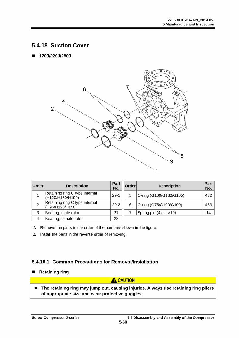
2205B0JE-DA-J-N_2014.05. 5 Maintenance and Inspection
Screw Compressor J-series 5.4 Disassembly and Assembly of the Compressor
5-60
5.4.18 Suction Cover
170J/220J/280J
Order Description Part No.
Order Description Part No.
1 Retaining ring C type internal (H120/H150/H190)
29-1 5 O-ring (G100/G130/G165) 432
2 Retaining ring C type internal (H95/H120/H150)
29-2 6 O-ring (G75/G100/G100) 433
3 Bearing, male rotor 27 7 Spring pin (4 dia.×10) 14
4 Bearing, female rotor 28
1. Remove the parts in the order of the numbers shown in the figure.
2. Install the parts in the reverse order of removing.
5.4.18.1 Common Precautions for Removal/Installation
Retaining ring
The retaining ring may jump out, causing injuries. Always use retaining ring pliers
of appropriate size and wear protective goggles.
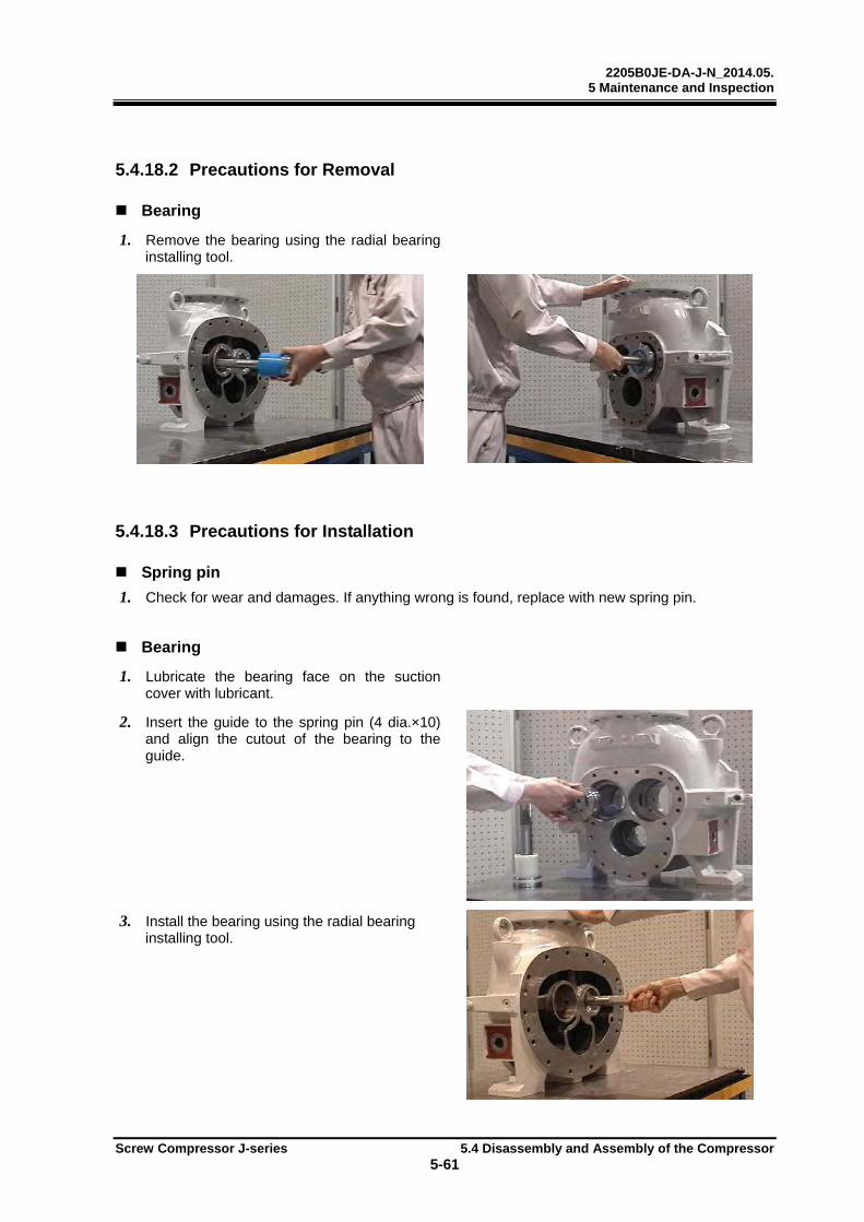
2205B0JE-DA-J-N_2014.05. 5 Maintenance and Inspection
Screw Compressor J-series 5.4 Disassembly and Assembly of the Compressor
5-61
5.4.18.2 Precautions for Removal
Bearing
1. Remove the bearing using the radial bearing installing tool.
5.4.18.3 Precautions for Installation
Spring pin
1. Check for wear and damages. If anything wrong is found, replace with new spring pin.
Bearing
1. Lubricate the bearing face on the suction cover with lubricant.
2. Insert the guide to the spring pin (4 dia.×10) and align the cutout of the bearing to the guide.
3. Install the bearing using the radial bearing installing tool.

2205B0JE-DA-J-N_2014.05. 5 Maintenance and Inspection
Screw Compressor J-series 5.4 Disassembly and Assembly of the Compressor
5-62
5.4.19 Rotors
170J/220J/280J
Order Description Part No.
Order Description Part No.
1 Key for balance piston 31 8 Push rod, Vi 292
2 Male rotor 25 9 Hexagon socket head cap screw (M8×30/M8×35/M10×40)
58
3 Female rotor 26 10 Spring lock washer (M8/M8/M10) 267
4 Unloader slide valve assembly and slide valve assembly, Vi
— 11 Gland, push rod for unloader slide valve
451
5 O-ring (P32) 325-1 12 Unloader push rod 67
6 Spiral retaining ring 293 13 Grooved pin 446
7 Slide valve, Vi 289 14 Unloader slide valve 54
1. Remove the parts in the order of the numbers shown in the figure.
2. Install the parts in the reverse order of removing.
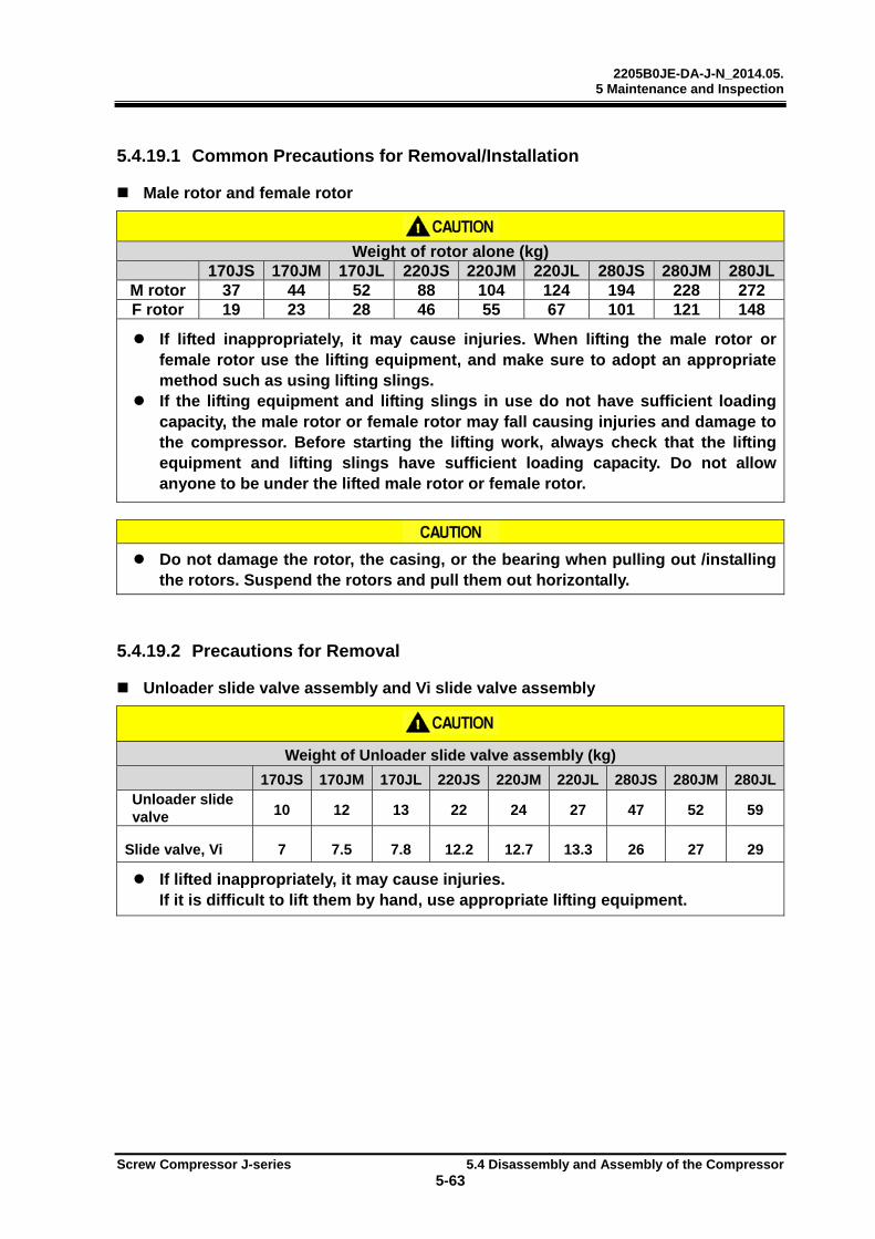
2205B0JE-DA-J-N_2014.05. 5 Maintenance and Inspection
Screw Compressor J-series 5.4 Disassembly and Assembly of the Compressor
5-63
5.4.19.1 Common Precautions for Removal/Installation
Male rotor and female rotor
Weight of rotor alone (kg)
170JS 170JM 170JL 220JS 220JM 220JL 280JS 280JM 280JLM rotor 37 44 52 88 104 124 194 228 272 F rotor 19 23 28 46 55 67 101 121 148
If lifted inappropriately, it may cause injuries. When lifting the male rotor or
female rotor use the lifting equipment, and make sure to adopt an appropriate method such as using lifting slings.
If the lifting equipment and lifting slings in use do not have sufficient loading capacity, the male rotor or female rotor may fall causing injuries and damage to the compressor. Before starting the lifting work, always check that the lifting equipment and lifting slings have sufficient loading capacity. Do not allow anyone to be under the lifted male rotor or female rotor.
Do not damage the rotor, the casing, or the bearing when pulling out /installing
the rotors. Suspend the rotors and pull them out horizontally.
5.4.19.2 Precautions for Removal
Unloader slide valve assembly and Vi slide valve assembly
Weight of Unloader slide valve assembly (kg)
170JS 170JM 170JL 220JS 220JM 220JL 280JS 280JM 280JL Unloader slide valve 10 12 13 22 24 27 47 52 59
Slide valve, Vi 7 7.5 7.8 12.2 12.7 13.3 26 27 29 If lifted inappropriately, it may cause injuries.
If it is difficult to lift them by hand, use appropriate lifting equipment.

2205B0JE-DA-J-N_2014.05. 5 Maintenance and Inspection
Screw Compressor J-series 5.4 Disassembly and Assembly of the Compressor
5-64
5.4.19.3 Precautions for Installation
Unloader push rod
1. Install the unloader push rod (Part No. 67) into the unloader slide valve (Part No. 54) with the grooved pin (Part No. 446) facing upward.
Push rod gland for unloader slide valve
1. When installing the push rod gland for unloader slide valve (No. 451) into the unloader slide valve (No. 54), align the cutout of the push rod gland with the grooved pin (No. 446) in the unloader slide valve push rod.
Male rotor and female rotor
1. Inspect the rotors for dents or scratches.
2. Using lifting slings, lift the female rotor horizontally and maintain the horizontal equilibrium.
3. Install the female rotor into the main rotor casing.
4. Using lifting slings, lift the male rotor horizontally and maintaining the horizontal equilibrium.
5. Engage the male rotor to the female rotor and push them into the main rotor casing.
The male rotor and female rotor can be engaged at any orientation.
Key for balance piston
1. Check for wear and damages. If anything wrong is found, replace the key.
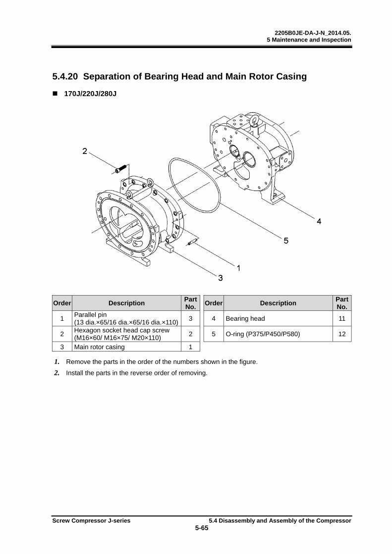
2205B0JE-DA-J-N_2014.05. 5 Maintenance and Inspection
Screw Compressor J-series 5.4 Disassembly and Assembly of the Compressor
5-65
5.4.20 Separation of Bearing Head and Main Rotor Casing
170J/220J/280J
Order Description Part No.
Order Description Part No.
1 Parallel pin (13 dia.×65/16 dia.×65/16 dia.×110)
3 4 Bearing head 11
2 Hexagon socket head cap screw (M16×60/ M16×75/ M20×110)
2 5 O-ring (P375/P450/P580) 12
3 Main rotor casing 1
1. Remove the parts in the order of the numbers shown in the figure.
2. Install the parts in the reverse order of removing.
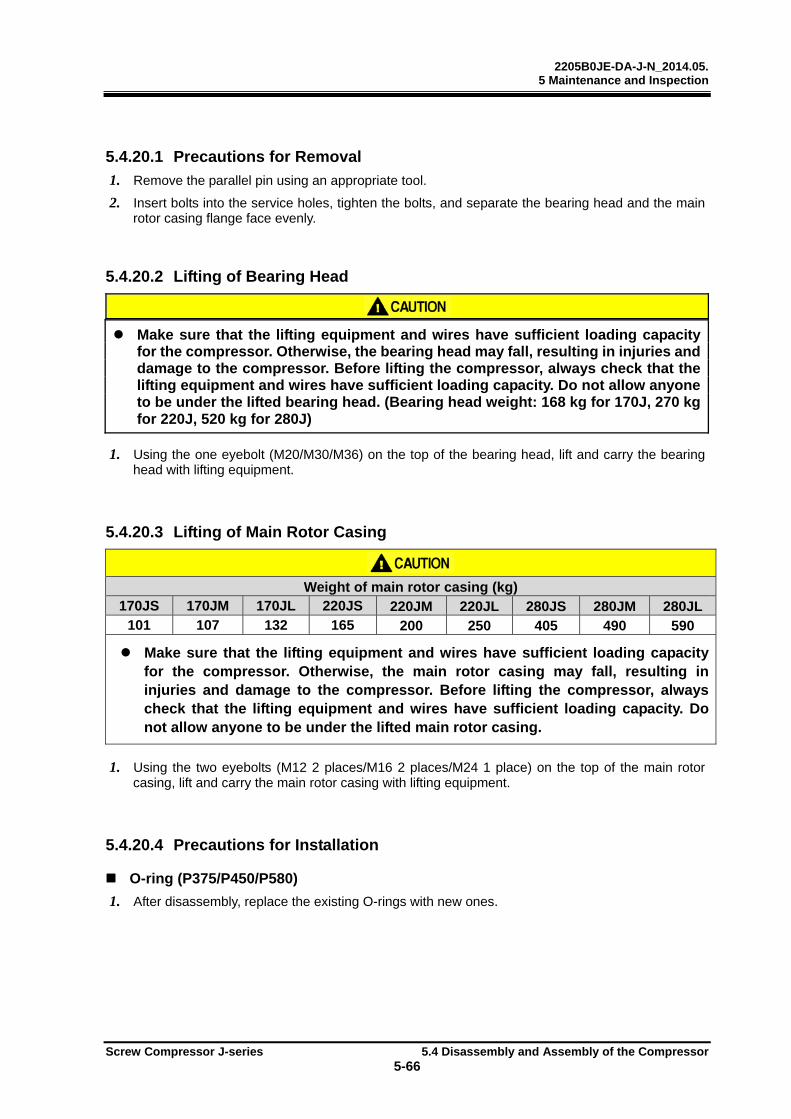
2205B0JE-DA-J-N_2014.05. 5 Maintenance and Inspection
Screw Compressor J-series 5.4 Disassembly and Assembly of the Compressor
5-66
5.4.20.1 Precautions for Removal
1. Remove the parallel pin using an appropriate tool.
2. Insert bolts into the service holes, tighten the bolts, and separate the bearing head and the main rotor casing flange face evenly.
5.4.20.2 Lifting of Bearing Head
Make sure that the lifting equipment and wires have sufficient loading capacity for the compressor. Otherwise, the bearing head may fall, resulting in injuries and damage to the compressor. Before lifting the compressor, always check that the lifting equipment and wires have sufficient loading capacity. Do not allow anyone to be under the lifted bearing head. (Bearing head weight: 168 kg for 170J, 270 kg for 220J, 520 kg for 280J)
1. Using the one eyebolt (M20/M30/M36) on the top of the bearing head, lift and carry the bearing head with lifting equipment.
5.4.20.3 Lifting of Main Rotor Casing
Weight of main rotor casing (kg) 170JS 170JM 170JL 220JS 220JM 220JL 280JS 280JM 280JL
101 107 132 165 200 250 405 490 590 Make sure that the lifting equipment and wires have sufficient loading capacity
for the compressor. Otherwise, the main rotor casing may fall, resulting in injuries and damage to the compressor. Before lifting the compressor, always check that the lifting equipment and wires have sufficient loading capacity. Do not allow anyone to be under the lifted main rotor casing.
1. Using the two eyebolts (M12 2 places/M16 2 places/M24 1 place) on the top of the main rotor casing, lift and carry the main rotor casing with lifting equipment.
5.4.20.4 Precautions for Installation
O-ring (P375/P450/P580)
1. After disassembly, replace the existing O-rings with new ones.
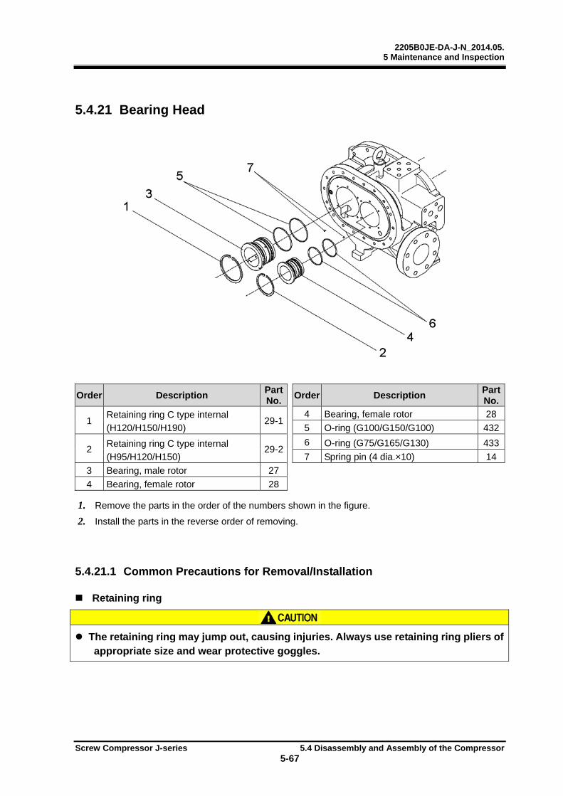
2205B0JE-DA-J-N_2014.05. 5 Maintenance and Inspection
Screw Compressor J-series 5.4 Disassembly and Assembly of the Compressor
5-67
5.4.21 Bearing Head
Order Description Part No.
Order Description Part No.
1 Retaining ring C type internal (H120/H150/H190)
29-14 Bearing, female rotor 28
5 O-ring (G100/G150/G100) 432
2 Retaining ring C type internal (H95/H120/H150)
29-26 O-ring (G75/G165/G130) 433
7 Spring pin (4 dia.×10) 14
3 Bearing, male rotor 27
4 Bearing, female rotor 28
1. Remove the parts in the order of the numbers shown in the figure.
2. Install the parts in the reverse order of removing.
5.4.21.1 Common Precautions for Removal/Installation
Retaining ring
The retaining ring may jump out, causing injuries. Always use retaining ring pliers of
appropriate size and wear protective goggles.

2205B0JE-DA-J-N_2014.05. 5 Maintenance and Inspection
Screw Compressor J-series 5.4 Disassembly and Assembly of the Compressor
5-68
5.4.21.2 Precautions for Removal
Bearing
1. Remove the bearing using the radial bearing installing tool.
5.4.21.3 Precautions for Installation
Spring pin
1. Check for wear and damages. If anything wrong is found, replace with new spring pin.
Bearing
1. Lubricate the bearing face of the bearing head with lubricant.
2. Insert the guide to the spring pin (4 dia.×10) and align the cutout of the bearing to the guide.
3. Install the bearing using the radial bearing installing tool.
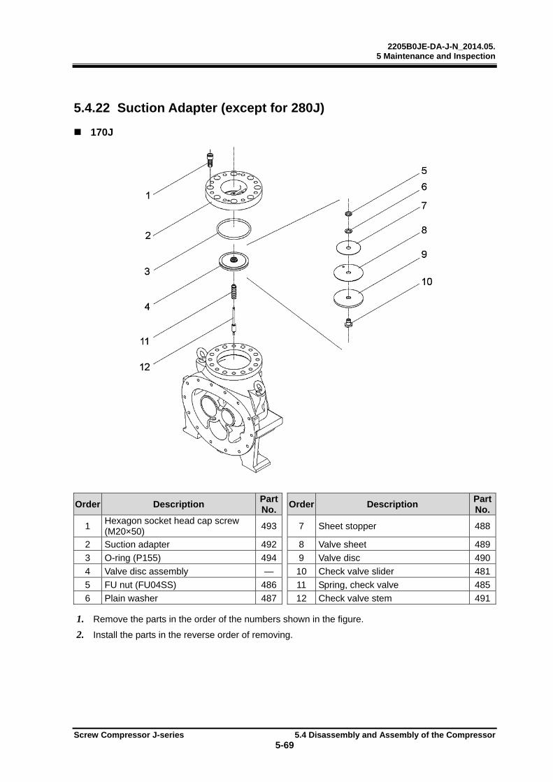
2205B0JE-DA-J-N_2014.05. 5 Maintenance and Inspection
Screw Compressor J-series 5.4 Disassembly and Assembly of the Compressor
5-69
5.4.22 Suction Adapter (except for 280J)
170J
Order Description Part No.
Order Description Part No.
1 Hexagon socket head cap screw (M20×50)
493 7 Sheet stopper 488
2 Suction adapter 492 8 Valve sheet 489
3 O-ring (P155) 494 9 Valve disc 490
4 Valve disc assembly — 10 Check valve slider 481
5 FU nut (FU04SS) 486 11 Spring, check valve 485
6 Plain washer 487 12 Check valve stem 491
1. Remove the parts in the order of the numbers shown in the figure.
2. Install the parts in the reverse order of removing.
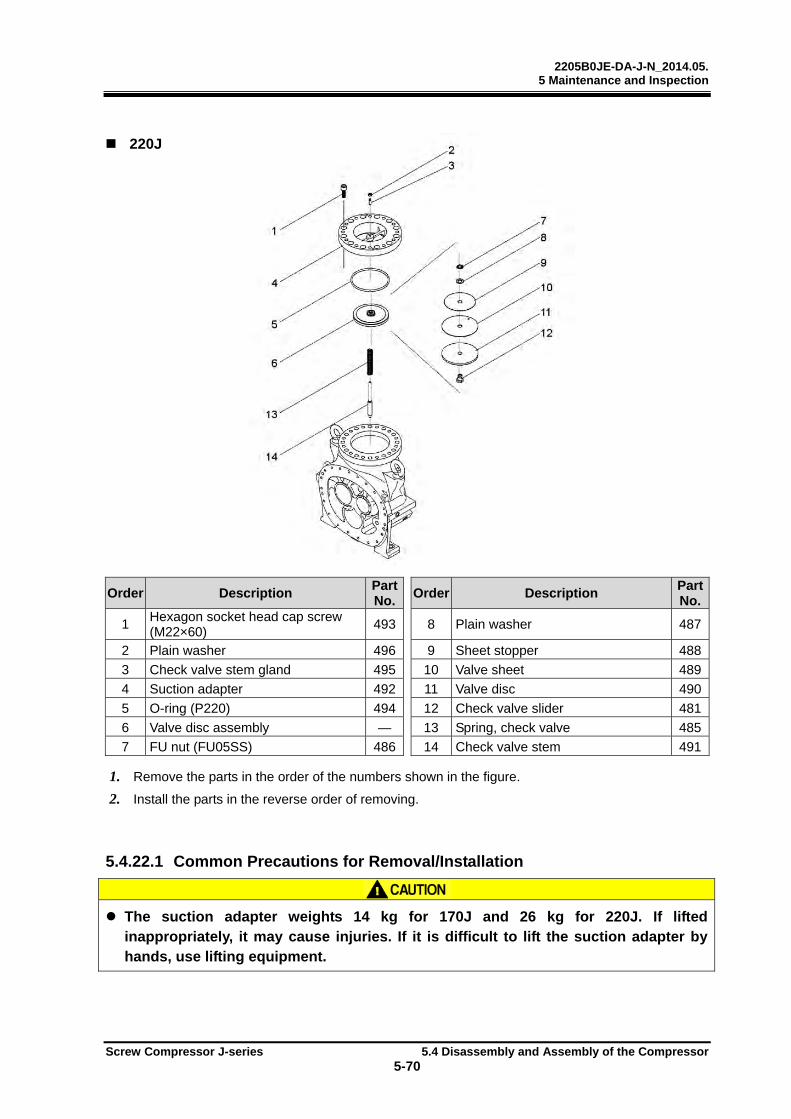
2205B0JE-DA-J-N_2014.05. 5 Maintenance and Inspection
Screw Compressor J-series 5.4 Disassembly and Assembly of the Compressor
5-70
220J
Order Description Part No.
Order Description Part No.
1 Hexagon socket head cap screw (M22×60)
493 8 Plain washer 487
2 Plain washer 496 9 Sheet stopper 488
3 Check valve stem gland 495 10 Valve sheet 489
4 Suction adapter 492 11 Valve disc 490
5 O-ring (P220) 494 12 Check valve slider 481
6 Valve disc assembly — 13 Spring, check valve 485
7 FU nut (FU05SS) 486 14 Check valve stem 491
1. Remove the parts in the order of the numbers shown in the figure.
2. Install the parts in the reverse order of removing.
5.4.22.1 Common Precautions for Removal/Installation
The suction adapter weights 14 kg for 170J and 26 kg for 220J. If lifted
inappropriately, it may cause injuries. If it is difficult to lift the suction adapter by hands, use lifting equipment.
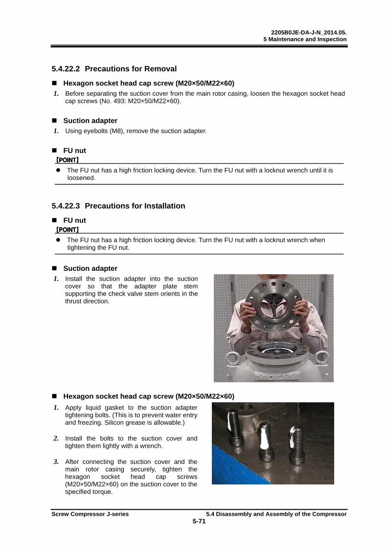
2205B0JE-DA-J-N_2014.05. 5 Maintenance and Inspection
Screw Compressor J-series 5.4 Disassembly and Assembly of the Compressor
5-71
5.4.22.2 Precautions for Removal
Hexagon socket head cap screw (M20×50/M22×60)
1. Before separating the suction cover from the main rotor casing, loosen the hexagon socket head cap screws (No. 493: M20×50/M22×60).
Suction adapter
1. Using eyebolts (M8), remove the suction adapter.
FU nut
The FU nut has a high friction locking device. Turn the FU nut with a locknut wrench until it is loosened.
5.4.22.3 Precautions for Installation
FU nut
The FU nut has a high friction locking device. Turn the FU nut with a locknut wrench when tightening the FU nut.
Suction adapter
1. Install the suction adapter into the suction cover so that the adapter plate stem supporting the check valve stem orients in the thrust direction.
Hexagon socket head cap screw (M20×50/M22×60)
1. Apply liquid gasket to the suction adapter tightening bolts. (This is to prevent water entry and freezing. Silicon grease is allowable.)
2. Install the bolts to the suction cover and tighten them lightly with a wrench.
3. After connecting the suction cover and the main rotor casing securely, tighten the hexagon socket head cap screws (M20×50/M22×60) on the suction cover to the specified torque.

2205B0JE-DA-J-N_2014.05. 5 Maintenance and Inspection
Screw Compressor J-series 5.4 Disassembly and Assembly of the Compressor
5-72
5.4.23 Unloader Slide Valve Guide
Order Description Part No.
Order Description Part No.
1 Parallel pin (8 dia.×60/8 dia.×80/13 dia.×100)
249 3 Spring lock washer 248
2 Hexagon socket head cap screw (M8×70/M8×90/M10×110)
247 4 Guide, unloader slide valve 246
1. Remove the parts in the order of the numbers shown in the figure.
2. Install the parts in the reverse order of removing.
For periodic inspection, do not remove the unloader slide valve guide.
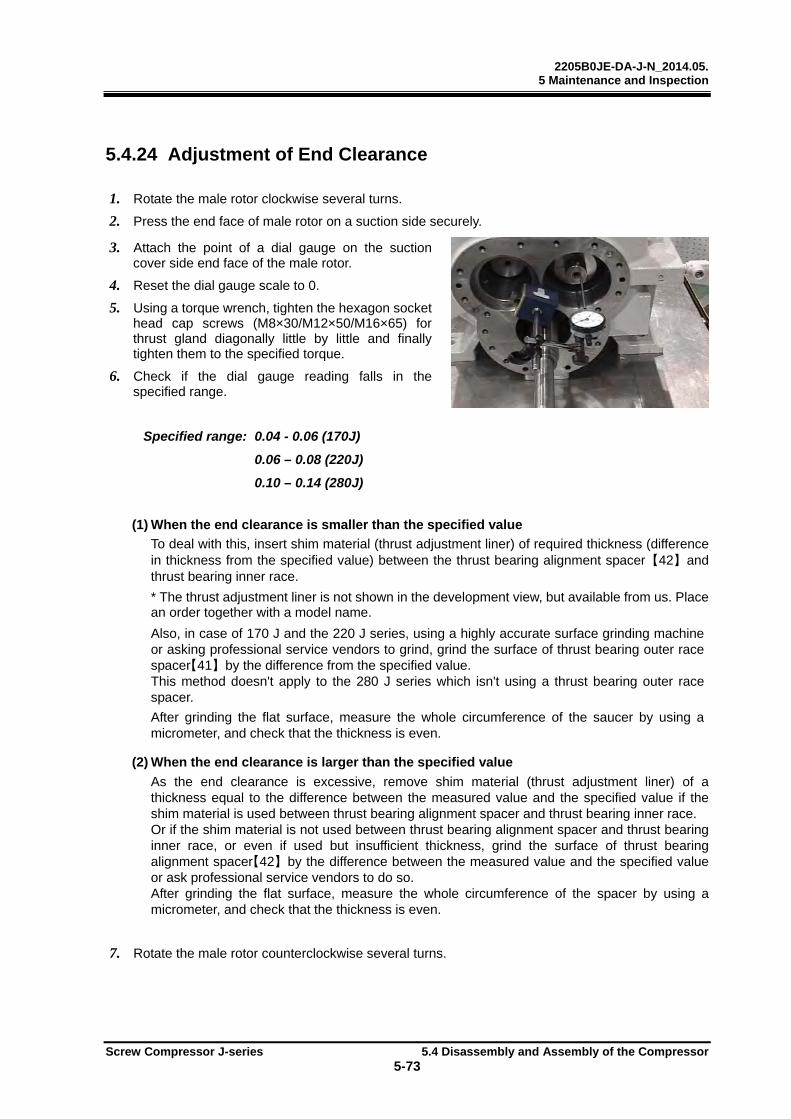
2205B0JE-DA-J-N_2014.05. 5 Maintenance and Inspection
Screw Compressor J-series 5.4 Disassembly and Assembly of the Compressor
5-73
5.4.24 Adjustment of End Clearance
1. Rotate the male rotor clockwise several turns.
2. Press the end face of male rotor on a suction side securely.
3. Attach the point of a dial gauge on the suction cover side end face of the male rotor.
4. Reset the dial gauge scale to 0.
5. Using a torque wrench, tighten the hexagon socket head cap screws (M8×30/M12×50/M16×65) for thrust gland diagonally little by little and finally tighten them to the specified torque.
6. Check if the dial gauge reading falls in the specified range.
Specified range: 0.04 - 0.06 (170J)
0.06 – 0.08 (220J)
0.10 – 0.14 (280J)
(1) When the end clearance is smaller than the specified value To deal with this, insert shim material (thrust adjustment liner) of required thickness (difference in thickness from the specified value) between the thrust bearing alignment spacer 【42】 and thrust bearing inner race. * The thrust adjustment liner is not shown in the development view, but available from us. Place an order together with a model name. Also, in case of 170 J and the 220 J series, using a highly accurate surface grinding machine or asking professional service vendors to grind, grind the surface of thrust bearing outer race spacer【41】 by the difference from the specified value. This method doesn't apply to the 280 J series which isn't using a thrust bearing outer race spacer. After grinding the flat surface, measure the whole circumference of the saucer by using a micrometer, and check that the thickness is even.
(2) When the end clearance is larger than the specified value As the end clearance is excessive, remove shim material (thrust adjustment liner) of a thickness equal to the difference between the measured value and the specified value if the shim material is used between thrust bearing alignment spacer and thrust bearing inner race. Or if the shim material is not used between thrust bearing alignment spacer and thrust bearing inner race, or even if used but insufficient thickness, grind the surface of thrust bearing alignment spacer【42】 by the difference between the measured value and the specified value or ask professional service vendors to do so. After grinding the flat surface, measure the whole circumference of the spacer by using a micrometer, and check that the thickness is even.
7. Rotate the male rotor counterclockwise several turns.
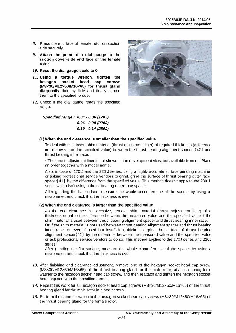
2205B0JE-DA-J-N_2014.05. 5 Maintenance and Inspection
Screw Compressor J-series 5.4 Disassembly and Assembly of the Compressor
5-74
8. Press the end face of female rotor on suction side securely.
9. Attach the point of a dial gauge to the suction cover-side end face of the female rotor.
10. Reset the dial gauge scale to 0.
11. Using a torque wrench, tighten the hexagon socket head cap screws (M8×30/M12×50/M16×65) for thrust gland diagonally little by little and finally tighten them to the specified torque.
12. Check if the dial gauge reads the specified range.
Specified range : 0.04 - 0.06 (170J)
0.06 - 0.08 (220J)
0.10 - 0.14 (280J)
(1) When the end clearance is smaller than the specified value To deal with this, insert shim material (thrust adjustment liner) of required thickness (difference in thickness from the specified value) between the thrust bearing alignment spacer 【42】 and thrust bearing inner race. * The thrust adjustment liner is not shown in the development view, but available from us. Place an order together with a model name. Also, in case of 170 J and the 220 J series, using a highly accurate surface grinding machine or asking professional service vendors to grind, grind the surface of thrust bearing outer race spacer【41】 by the difference from the specified value. This method doesn't apply to the 280 J series which isn't using a thrust bearing outer race spacer. After grinding the flat surface, measure the whole circumference of the saucer by using a micrometer, and check that the thickness is even.
(2) When the end clearance is larger than the specified value As the end clearance is excessive, remove shim material (thrust adjustment liner) of a thickness equal to the difference between the measured value and the specified value if the shim material is used between thrust bearing alignment spacer and thrust bearing inner race. Or if the shim material is not used between thrust bearing alignment spacer and thrust bearing inner race, or even if used but insufficient thickness, grind the surface of thrust bearing alignment spacer【42】 by the difference between the measured value and the specified value or ask professional service vendors to do so. This method applies to the 170J series and 220J series. After grinding the flat surface, measure the whole circumference of the spacer by using a micrometer, and check that the thickness is even.
13. After finishing end clearance adjustment, remove one of the hexagon socket head cap screw (M8×30/M12×50/M16×65) of the thrust bearing gland for the male rotor, attach a spring lock washer to the hexagon socket head cap screw, and then reattach and tighten the hexagon socket head cap screw to the specified torque.
14. Repeat this work for all hexagon socket head cap screws (M8×30/M12×50/M16×65) of the thrust bearing gland for the male rotor in a star pattern.
15. Perform the same operation to the hexagon socket head cap screws (M8×30/M12×50/M16×65) of the thrust bearing gland for the female rotor.
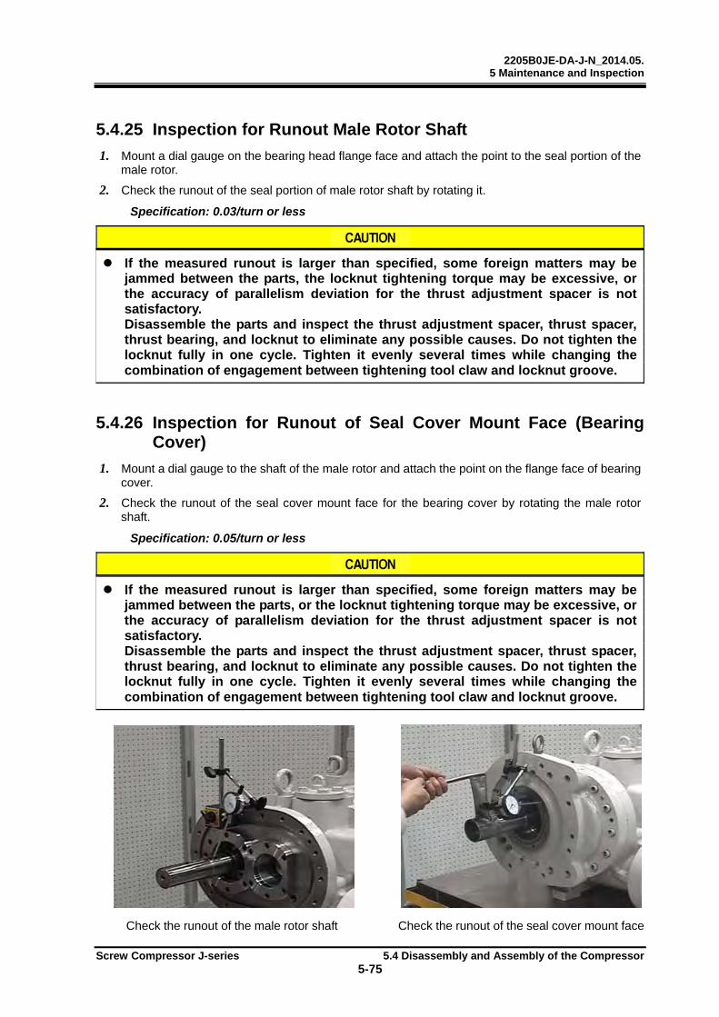
2205B0JE-DA-J-N_2014.05. 5 Maintenance and Inspection
Screw Compressor J-series 5.4 Disassembly and Assembly of the Compressor
5-75
5.4.25 Inspection for Runout Male Rotor Shaft
1. Mount a dial gauge on the bearing head flange face and attach the point to the seal portion of the male rotor.
2. Check the runout of the seal portion of male rotor shaft by rotating it.
Specification: 0.03/turn or less
If the measured runout is larger than specified, some foreign matters may be jammed between the parts, the locknut tightening torque may be excessive, or the accuracy of parallelism deviation for the thrust adjustment spacer is not satisfactory. Disassemble the parts and inspect the thrust adjustment spacer, thrust spacer, thrust bearing, and locknut to eliminate any possible causes. Do not tighten the locknut fully in one cycle. Tighten it evenly several times while changing the combination of engagement between tightening tool claw and locknut groove.
5.4.26 Inspection for Runout of Seal Cover Mount Face (Bearing Cover)
1. Mount a dial gauge to the shaft of the male rotor and attach the point on the flange face of bearing cover.
2. Check the runout of the seal cover mount face for the bearing cover by rotating the male rotor shaft.
Specification: 0.05/turn or less
If the measured runout is larger than specified, some foreign matters may be jammed between the parts, or the locknut tightening torque may be excessive, or the accuracy of parallelism deviation for the thrust adjustment spacer is not satisfactory. Disassemble the parts and inspect the thrust adjustment spacer, thrust spacer, thrust bearing, and locknut to eliminate any possible causes. Do not tighten the locknut fully in one cycle. Tighten it evenly several times while changing the combination of engagement between tightening tool claw and locknut groove.
Check the runout of the male rotor shaft Check the runout of the seal cover mount face
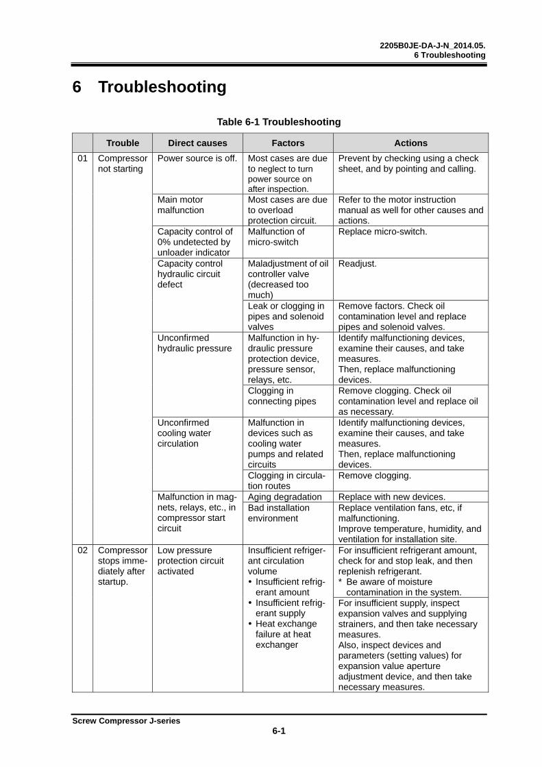
2205B0JE-DA-J-N_2014.05. 6 Troubleshooting
Screw Compressor J-series 6-1
6 Troubleshooting
Table 6-1 Troubleshooting
Trouble Direct causes Factors Actions
01 Compressor not starting
Power source is off. Most cases are due to neglect to turn power source on after inspection.
Prevent by checking using a check sheet, and by pointing and calling.
Main motor malfunction
Most cases are due to overload protection circuit.
Refer to the motor instruction manual as well for other causes and actions.
Capacity control of 0% undetected by unloader indicator
Malfunction of micro-switch
Replace micro-switch.
Capacity control hydraulic circuit defect
Maladjustment of oil controller valve (decreased too much)
Readjust.
Leak or clogging in pipes and solenoid valves
Remove factors. Check oil contamination level and replace pipes and solenoid valves.
Unconfirmed hydraulic pressure
Malfunction in hy-draulic pressure protection device, pressure sensor, relays, etc.
Identify malfunctioning devices, examine their causes, and take measures. Then, replace malfunctioning devices.
Clogging in connecting pipes
Remove clogging. Check oil contamination level and replace oil as necessary.
Unconfirmed cooling water circulation
Malfunction in devices such as cooling water pumps and related circuits
Identify malfunctioning devices, examine their causes, and take measures. Then, replace malfunctioning devices.
Clogging in circula-tion routes
Remove clogging.
Malfunction in mag-nets, relays, etc., in compressor start circuit
Aging degradation Replace with new devices. Bad installation environment
Replace ventilation fans, etc, if malfunctioning. Improve temperature, humidity, and ventilation for installation site.
02
Compressor stops imme-diately after startup.
Low pressure protection circuit activated
Insufficient refriger-ant circulation volume Insufficient refrig-
erant amount Insufficient refrig-
erant supply Heat exchange
failure at heat exchanger
For insufficient refrigerant amount, check for and stop leak, and then replenish refrigerant. * Be aware of moisture
contamination in the system. For insufficient supply, inspect expansion valves and supplying strainers, and then take necessary measures. Also, inspect devices and parameters (setting values) for expansion value aperture adjustment device, and then take necessary measures.
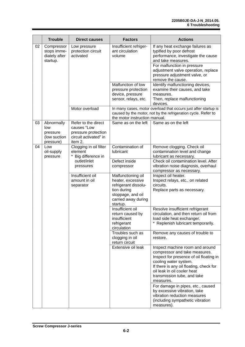
2205B0JE-DA-J-N_2014.05. 6 Troubleshooting
Screw Compressor J-series 6-2
Trouble Direct causes Factors Actions
02 Compressor stops imme-diately after startup.
Low pressure protection circuit activated
Insufficient refriger-ant circulation volume
If any heat exchange failures as typified by poor defrost performance, investigate the cause and take measures. For malfunction in pressure adjustment valve operation, replace pressure adjustment valve, or remove the cause.
Malfunction of low pressure protection device, pressure sensor, relays, etc.
Identify malfunctioning devices, examine their causes, and take measures. Then, replace malfunctioning devices.
Motor overload In many cases, motor overload that occurs just after startup is caused by the motor, not by the refrigeration cycle. Refer to the motor instruction manual.
03 Abnormally low pressure (low suction pressure)
Refer to the direct causes “Low pressure protection circuit activated” in item 2.
Same as on the left
Same as on the left
04
Low oil-supply pressure
Clogging in oil filter element * Big difference in
outlet/inlet pressures
Contamination of lubricant
Remove clogging. Check oil contamination level and change lubricant as necessary.
Defect inside compressor
Check oil contamination level. After vibration noise diagnosis, overhaul compressor as necessary.
Insufficient oil amount in oil separator
Malfunctioning oil heater, excessive refrigerant dissolu-tion during stoppage, and oil carried away during startup.
Inspect oil heater. Inspect relays, etc., on related circuits. Replace parts as necessary.
Insufficient oil return caused by insufficient refrigerant circulation
Resolve insufficient refrigerant circulation, and then return oil from load side heat exchanger. * Replenish lubricant temporarily.
Troubles such as clogging in oil return circuit
Remove any causes of trouble to restore.
Extensive oil leak
Inspect machine room and around compressor and take measures. Inspect for presence of oil floating in cooling water system. If there is any oil floating, check for oil leak in oil cooler heat transmission tube, and take measures. For damage in pipes, etc., caused by excessive vibration, take vibration reduction measures (including sympathetic vibration measures).

2205B0JE-DA-J-N_2014.05. 6 Troubleshooting
Screw Compressor J-series 6-3
Trouble Direct causes Factors Actions
04
Low oil-supply pressure
Defect in hydraulic pressure detection feature.
Malfunction in hydraulic pressure protection device, pressure sensor, relays, etc.
Identify malfunctioning devices, examine their causes, and take measures. Then, replace malfunctioning devices.
Clogging in connecting pipes
Remove clogging. Check oil contamination level and replace oil as necessary.
05
Abnormally high pressure (abnormal discharge pressure)
Heat exchange failure at condenser (heat exchanger)
Contaminated and blocked heat trans-mission tubes, fins, etc.
Clean and wash them. Use solvent to clean depending on contamination.
Malfunction of fan motor, thermo-switch, water spray bars, cooling water pumps, etc. (including waterfall)
Identify malfunctioning devices, examine their causes, and take measures. Then, replace malfunctioning devices.
Flow volume adjustment fault for cooling water, brine, etc.
If valve is manually adjusted, readjust it. If an automatic control valve (including wax valve) is used, examine its cause and take measures.
Other insufficient circulation volume problems of cooling water, etc.
Inspect for clogging and contamination of circulation route filters, and take measures. Inspect for leak in circulation routes, and take measures. Inspect water supply routes and construction, and take measures. If frozen, improve by insulation or heating.
Poor performance in heat exchanger
If the trouble is caused by change in operating conditions, re-examine the conditions to improve. If the trouble is caused by change in installation environment, improve the environment if possible. For both cases, if it is difficult to improve, add more heat exchangers or increase their sizes.
Uncondensed gas in the system
Leak on low pressure side * Cases of erosion
of compressor’s suction thermometer protection pipe have also been confirmed.
Inspect for leak, and take necessary measures. Then, air purge the heat exchanger.
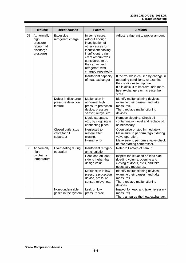
2205B0JE-DA-J-N_2014.05. 6 Troubleshooting
Screw Compressor J-series 6-4
Trouble Direct causes Factors Actions
05
Abnormally high pressure (abnormal discharge pressure)
Excessive refrigerant charge
In some cases, without enough investigation of other causes for insufficient cooling, insufficient refrig-erant amount was considered to be the cause, and refrigerant was charged repeatedly.
Adjust refrigerant to proper amount.
Insufficient capacity of heat exchanger
If the trouble is caused by change in operating conditions, re-examine the conditions to improve. If it is difficult to improve, add more heat exchangers or increase their sizes.
Defect in discharge pressure detection feature
Malfunction in abnormal high pressure protection device, pressure sensor, relays, etc.
Identify malfunctioning devices, examine their causes, and take measures. Then, replace malfunctioning devices.
Liquid stoppage, etc., by clogging in connecting pipes
Remove clogging. Check oil contamination level and replace oil as necessary.
Closed outlet stop valve for oil separator
Neglected to restore after closing. Human error
Open valve or stop immediately. Make sure to perform tagout during valve operation. Make sure to perform a valve check before starting compressor.
06 Abnormally high discharge temperature
Overheating during operation
Insufficient refriger-ant circulation
Refer to Factors of item 02.
Heat load on load side is higher than design value.
Inspect the situation on load side (loading volume, opening and closing of doors, etc.), and take necessary measures.
Malfunction in low pressure protection device, pressure sensor, relays, etc.
Identify malfunctioning devices, examine their causes, and take measures. Then, replace malfunctioning devices.
Non-condensable gases in the system
Leak on low pressure side
Inspect for leak, and take necessary measures. Then, air purge the heat exchanger.

2205B0JE-DA-J-N_2014.05. 6 Troubleshooting
Screw Compressor J-series 6-5
Trouble Direct causes Factors Actions
06 Abnormally high discharge temperature
High supply oil temperature
Heat exchange fault in oil cooler
For water-cooling types, refer to “Heat exchange failure at condenser (heat exchanger)” in item 05. For liquid cooling type, inspect liquid supply expansion valve, temperature sensor, related relays, wiring, terminals, etc., and take measures.
Failure in oil temperature increase protection feature
Inspect temperature protection device, temperature sensor, related relays, wiring, terminals, etc., and take measures.
Defect in discharge temperature detection and protection features
Malfunction in temperature protec-tion device, temperature sensor, relays, etc.
Identify malfunctioning devices, examine their causes, and take measures. Then, replace malfunctioning devices.
Insufficient supply oil
Refer to item 04, “Low hydraulic pressure (low oil-supply pres-sure)”.
Same as on the left
07
Leak from mechanical seal
Initial leak after replacement until sliding surfaces fit together
This happens because of the specific operating conditions of the compressor and unsteadiness in bearing pressure condition of processed sliding surfaces following replacement.
For initial leak, amount of leak might increase temporarily. However, it will gradually decrease, so check that the amount of leak does not increase continuously. Period of initial leak might differ according to design and operating conditions. 200 hours can be a rough guide.
Damaged sliding surfaces due to excessive heat of sliding surfaces
Most cases are due to excessive repetition of startup/stoppage. * For a standard
device, more than 4 times per hour is considered too many.
If heat load is below the device’s design conditions, re-examine operating conditions. Set the control settings to fewer startup/stoppage times. For capacity control malfunctions, see item 10, “Capacity control malfunction”.
A lot of refrigerant mixed into the lubricant, resulting in decreased viscosity.
For liquid backflow operation, remove the causes. For malfunction of oil heater and other devices on control circuit, replace them.
Overheat operation Refer to Factor “Insufficient refrigerant circulation volume” in item 02.
High supply oil temperature
Refer to the Direct cause “High supply oil temperature” in item 06.
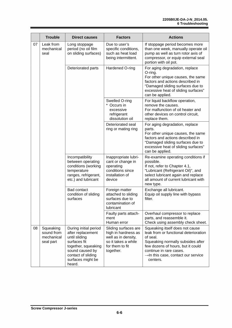
2205B0JE-DA-J-N_2014.05. 6 Troubleshooting
Screw Compressor J-series 6-6
Trouble Direct causes Factors Actions
07
Leak from mechanical seal
Long stoppage period (no oil film on sliding surfaces)
Due to user’s specific conditions, such as heat load being intermittent.
If stoppage period becomes more than one week, manually operate oil pump as well as turn rotor axis of compressor, or equip external seal portion with oil pot.
Deteriorated parts
Hardened O-ring For aging degradation, replace O-ring. For other unique causes, the same factors and actions described in “Damaged sliding surfaces due to excessive heat of sliding surfaces” can be applied.
Swelled O-ring * Occurs in
excessive refrigerant dissolution oil
For liquid backflow operation, remove the causes. For malfunction of oil heater and other devices on control circuit, replace them.
Deteriorated seal ring or mating ring
For aging degradation, replace parts. For other unique causes, the same factors and actions described in “Damaged sliding surfaces due to excessive heat of sliding surfaces” can be applied.
Incompatibility between operating conditions (working temperature ranges, refrigerant, etc.) and lubricant
Inappropriate lubri-cant or change in operating conditions since installation of device
Re-examine operating conditions if possible. If not, refer to Chapter 4.1, “Lubricant (Refrigerant Oil)”, and select lubricant again and replace all amount of current lubricant with new type.
Bad contact condition of sliding surfaces
Foreign matter attached to sliding surfaces due to contamination of lubricant
Exchange all lubricant. Equip oil supply line with bypass filter.
Faulty parts attach-ment Human error
Overhaul compressor to replace parts, and reassemble it. Check using assembly check sheet.
08 Squeaking sound from mechanical seal part
During initial period after replacement until sliding surfaces fit together, squeaking sound caused by contact of sliding surfaces might be heard.
Sliding surfaces are high in hardness as well as in density, so it takes a while for them to fit together.
Squeaking itself does not cause leak from or functional deterioration of seal. Squeaking normally subsides after few dozens of hours, but it could continue in rare cases. →In this case, contact our service
centers.
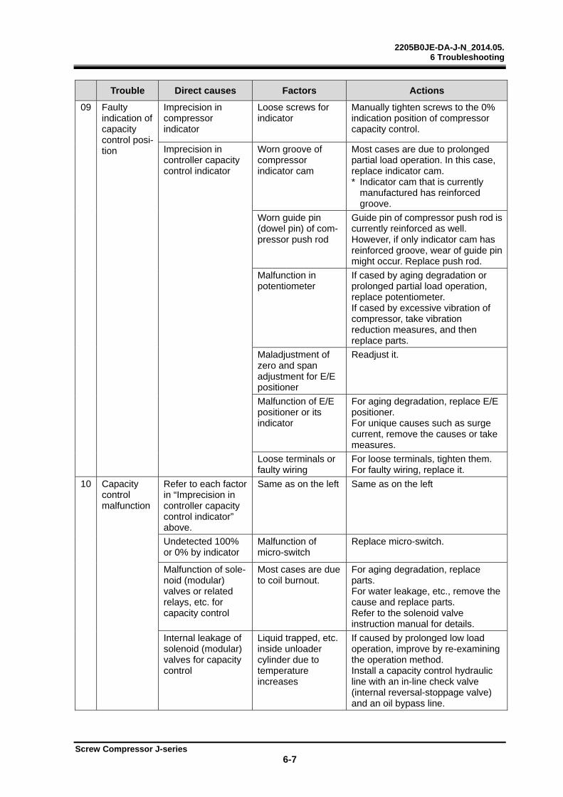
2205B0JE-DA-J-N_2014.05. 6 Troubleshooting
Screw Compressor J-series 6-7
Trouble Direct causes Factors Actions
09 Faulty indication of capacity control posi-tion
Imprecision in compressor indicator
Loose screws for indicator
Manually tighten screws to the 0% indication position of compressor capacity control.
Imprecision in controller capacity control indicator
Worn groove of compressor indicator cam
Most cases are due to prolonged partial load operation. In this case, replace indicator cam. * Indicator cam that is currently
manufactured has reinforced groove.
Worn guide pin (dowel pin) of com-pressor push rod
Guide pin of compressor push rod is currently reinforced as well. However, if only indicator cam has reinforced groove, wear of guide pin might occur. Replace push rod.
Malfunction in potentiometer
If cased by aging degradation or prolonged partial load operation, replace potentiometer. If cased by excessive vibration of compressor, take vibration reduction measures, and then replace parts.
Maladjustment of zero and span adjustment for E/E positioner
Readjust it.
Malfunction of E/E positioner or its indicator
For aging degradation, replace E/E positioner. For unique causes such as surge current, remove the causes or take measures.
Loose terminals or faulty wiring
For loose terminals, tighten them. For faulty wiring, replace it.
10
Capacity control malfunction
Refer to each factor in “Imprecision in controller capacity control indicator” above.
Same as on the left Same as on the left
Undetected 100% or 0% by indicator
Malfunction of micro-switch
Replace micro-switch.
Malfunction of sole-noid (modular) valves or related relays, etc. for capacity control
Most cases are due to coil burnout.
For aging degradation, replace parts. For water leakage, etc., remove the cause and replace parts. Refer to the solenoid valve instruction manual for details.
Internal leakage of solenoid (modular) valves for capacity control
Liquid trapped, etc. inside unloader cylinder due to temperature increases
If caused by prolonged low load operation, improve by re-examining the operation method. Install a capacity control hydraulic line with an in-line check valve (internal reversal-stoppage valve) and an oil bypass line.
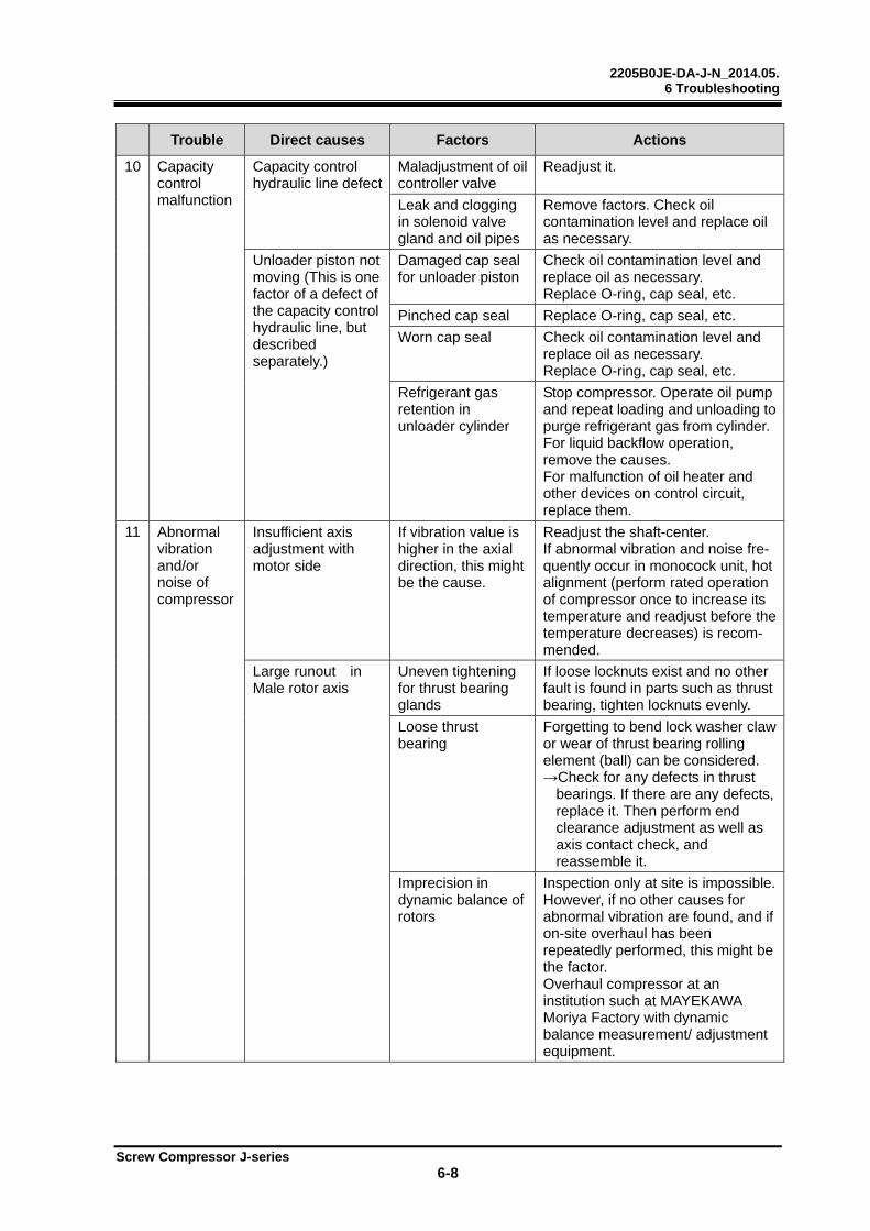
2205B0JE-DA-J-N_2014.05. 6 Troubleshooting
Screw Compressor J-series 6-8
Trouble Direct causes Factors Actions
10 Capacity control malfunction
Capacity control hydraulic line defect
Maladjustment of oil controller valve
Readjust it.
Leak and clogging in solenoid valve gland and oil pipes
Remove factors. Check oil contamination level and replace oil as necessary.
Unloader piston not moving (This is one factor of a defect of the capacity control hydraulic line, but described separately.)
Damaged cap seal for unloader piston
Check oil contamination level and replace oil as necessary. Replace O-ring, cap seal, etc.
Pinched cap seal Replace O-ring, cap seal, etc.
Worn cap seal Check oil contamination level and replace oil as necessary. Replace O-ring, cap seal, etc.
Refrigerant gas retention in unloader cylinder
Stop compressor. Operate oil pump and repeat loading and unloading to purge refrigerant gas from cylinder. For liquid backflow operation, remove the causes. For malfunction of oil heater and other devices on control circuit, replace them.
11
Abnormal vibration and/or noise of compressor
Insufficient axis adjustment with motor side
If vibration value is higher in the axial direction, this might be the cause.
Readjust the shaft-center. If abnormal vibration and noise fre-quently occur in monocock unit, hot alignment (perform rated operation of compressor once to increase its temperature and readjust before the temperature decreases) is recom-mended.
Large runout in Male rotor axis
Uneven tightening for thrust bearing glands
If loose locknuts exist and no other fault is found in parts such as thrust bearing, tighten locknuts evenly.
Loose thrust bearing
Forgetting to bend lock washer claw or wear of thrust bearing rolling element (ball) can be considered. →Check for any defects in thrust
bearings. If there are any defects, replace it. Then perform end clearance adjustment as well as axis contact check, and reassemble it.
Imprecision in dynamic balance of rotors
Inspection only at site is impossible. However, if no other causes for abnormal vibration are found, and if on-site overhaul has been repeatedly performed, this might be the factor. Overhaul compressor at an institution such at MAYEKAWA Moriya Factory with dynamic balance measurement/ adjustment equipment.
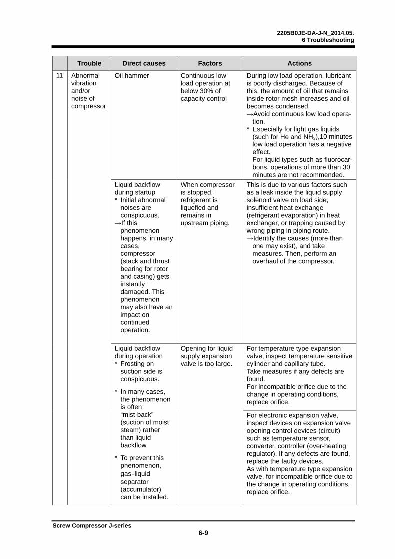
2205B0JE-DA-J-N_2014.05. 6 Troubleshooting
Screw Compressor J-series 6-9
Trouble Direct causes Factors Actions
11
Abnormal vibration and/or noise of compressor
Oil hammer Continuous low load operation at below 30% of capacity control
During low load operation, lubricant is poorly discharged. Because of this, the amount of oil that remains inside rotor mesh increases and oil becomes condensed. →Avoid continuous low load opera-
tion. * Especially for light gas liquids
(such for He and NH3),10 minutes low load operation has a negative effect.
For liquid types such as fluorocar-bons, operations of more than 30 minutes are not recommended.
Liquid backflow during startup * Initial abnormal
noises are conspicuous.
→If this phenomenon happens, in many cases, compressor (stack and thrust bearing for rotor and casing) gets instantly damaged. This phenomenon may also have an impact on continued operation.
When compressor is stopped, refrigerant is liquefied and remains in upstream piping.
This is due to various factors such as a leak inside the liquid supply solenoid valve on load side, insufficient heat exchange (refrigerant evaporation) in heat exchanger, or trapping caused by wrong piping in piping route. →Identify the causes (more than
one may exist), and take measures. Then, perform an overhaul of the compressor.
Liquid backflow during operation * Frosting on
suction side is conspicuous.
* In many cases, the phenomenon is often “mist-back” (suction of moist steam) rather than liquid backflow.
* To prevent this phenomenon, gas‐liquid separator (accumulator) can be installed.
Opening for liquid supply expansion valve is too large.
For temperature type expansion valve, inspect temperature sensitive cylinder and capillary tube. Take measures if any defects are found. For incompatible orifice due to the change in operating conditions, replace orifice.
For electronic expansion valve, inspect devices on expansion valve opening control devices (circuit) such as temperature sensor, converter, controller (over-heating regulator). If any defects are found, replace the faulty devices. As with temperature type expansion valve, for incompatible orifice due to the change in operating conditions, replace orifice.
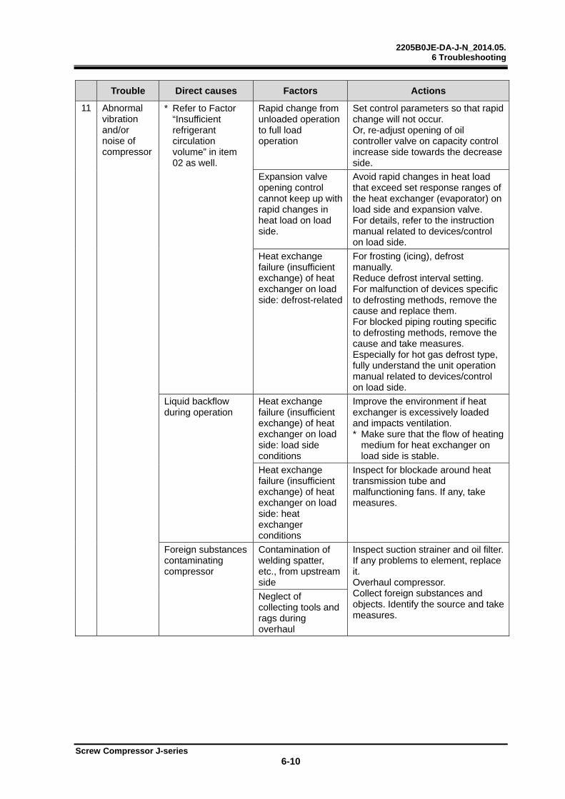
2205B0JE-DA-J-N_2014.05. 6 Troubleshooting
Screw Compressor J-series 6-10
Trouble Direct causes Factors Actions
11
Abnormal vibration and/or noise of compressor
* Refer to Factor “Insufficient refrigerant circulation volume” in item 02 as well.
Rapid change from unloaded operation to full load operation
Set control parameters so that rapid change will not occur. Or, re-adjust opening of oil controller valve on capacity control increase side towards the decrease side.
Expansion valve opening control cannot keep up with rapid changes in heat load on load side.
Avoid rapid changes in heat load that exceed set response ranges of the heat exchanger (evaporator) on load side and expansion valve. For details, refer to the instruction manual related to devices/control on load side.
Heat exchange failure (insufficient exchange) of heat exchanger on load side: defrost-related
For frosting (icing), defrost manually. Reduce defrost interval setting. For malfunction of devices specific to defrosting methods, remove the cause and replace them. For blocked piping routing specific to defrosting methods, remove the cause and take measures. Especially for hot gas defrost type, fully understand the unit operation manual related to devices/control on load side.
Liquid backflow during operation
Heat exchange failure (insufficient exchange) of heat exchanger on load side: load side conditions
Improve the environment if heat exchanger is excessively loaded and impacts ventilation. * Make sure that the flow of heating
medium for heat exchanger on load side is stable.
Heat exchange failure (insufficient exchange) of heat exchanger on load side: heat exchanger conditions
Inspect for blockade around heat transmission tube and malfunctioning fans. If any, take measures.
Foreign substances contaminating compressor
Contamination of welding spatter, etc., from upstream side
Inspect suction strainer and oil filter. If any problems to element, replace it. Overhaul compressor. Collect foreign substances and objects. Identify the source and take measures.
Neglect of collecting tools and rags during overhaul
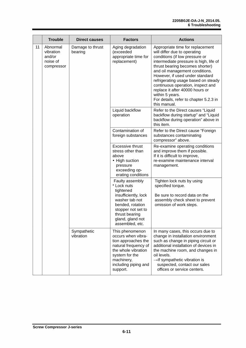
2205B0JE-DA-J-N_2014.05. 6 Troubleshooting
Screw Compressor J-series 6-11
Trouble Direct causes Factors Actions
11
Abnormal vibration and/or noise of compressor
Damage to thrust bearing
Aging degradation (exceeded appropriate time for replacement)
Appropriate time for replacement will differ due to operating conditions (if low pressure or intermediate pressure is high, life of thrust bearing becomes shorter) and oil management conditions. However, if used under standard refrigerating usage based on steady continuous operation, inspect and replace it after 40000 hours or within 5 years. For details, refer to chapter 5.2.3 in this manual.
Liquid backflow operation
Refer to the Direct causes “Liquid backflow during startup” and “Liquid backflow during operation” above in this item.
Contamination of foreign substances
Refer to the Direct cause “Foreign substances contaminating compressor” above.
Excessive thrust stress other than above High suction
pressure exceeding op-erating conditions
Re-examine operating conditions and improve them if possible. If it is difficult to improve, re-examine maintenance interval management.
Faulty assembly * Lock nuts
tightened insufficiently, lock washer tab not bended, rotation stopper not set to thrust bearing gland, gland not assembled, etc.
Tighten lock nuts by using specified torque. Be sure to record data on the assembly check sheet to prevent omission of work steps.
Sympathetic vibration
This phenomenon occurs when vibra-tion approaches the natural frequency of the whole vibration system for the machinery, including piping and support.
In many cases, this occurs due to change in installation environment such as change in piping circuit or additional installation of devices in the machine room, and changes in oil levels. →If sympathetic vibration is
suspected, contact our sales offices or service centers.
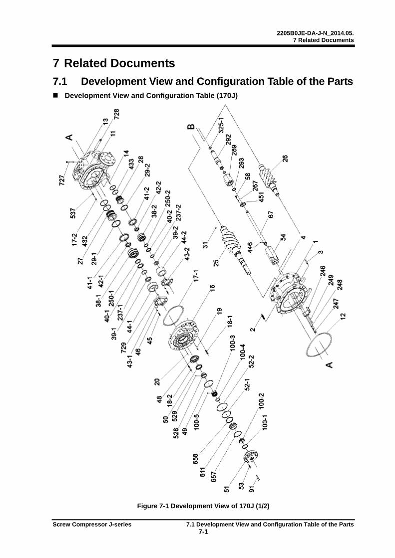
2205B0JE-DA-J-N_2014.05. 7 Related Documents
Screw Compressor J-series 7.1 Development View and Configuration Table of the Parts 7-1
7 Related Documents
7.1 Development View and Configuration Table of the Parts Development View and Configuration Table (170J)
Figure 7-1 Development View of 170J (1/2)
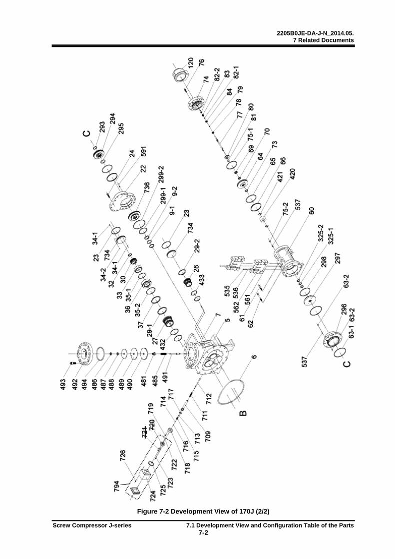
2205B0JE-DA-J-N_2014.05. 7 Related Documents
Screw Compressor J-series 7.1 Development View and Configuration Table of the Parts 7-2
Figure 7-2 Development View of 170J (2/2)
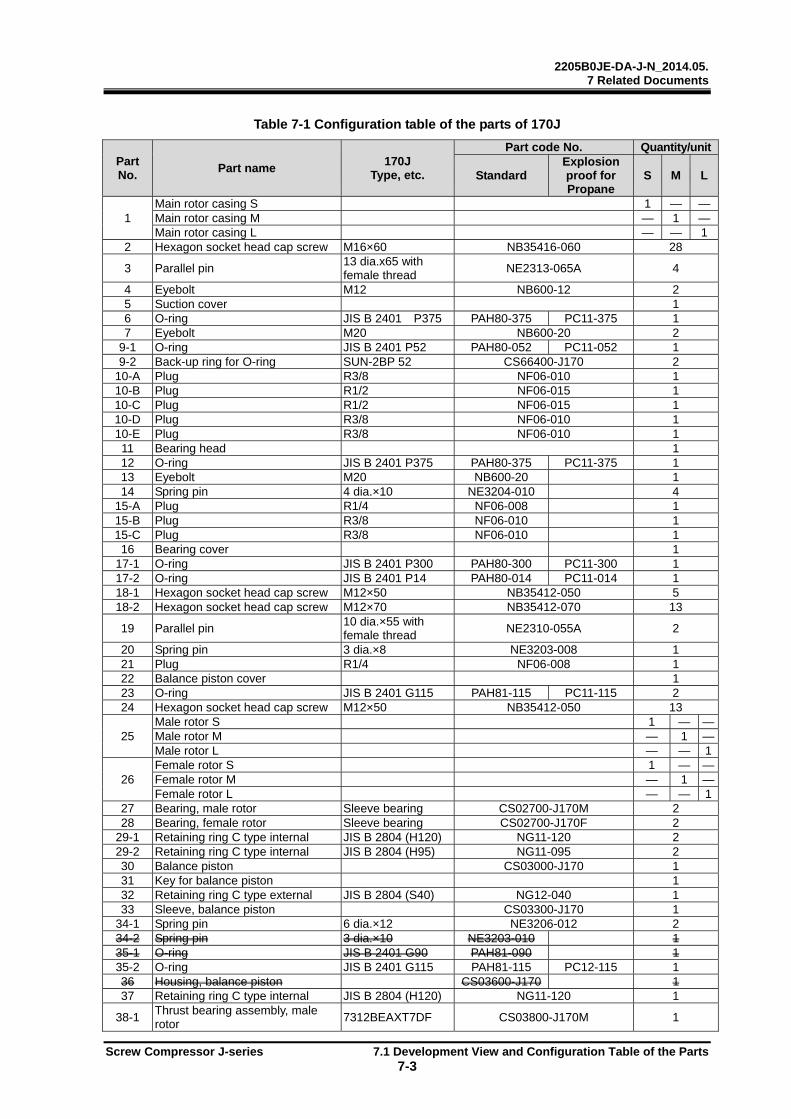
2205B0JE-DA-J-N_2014.05. 7 Related Documents
Screw Compressor J-series 7.1 Development View and Configuration Table of the Parts 7-3
Table 7-1 Configuration table of the parts of 170J
Part No.
Part name 170J
Type, etc.
Part code No. Quantity/unit
Standard Explosion proof for Propane
S M L
1 Main rotor casing S 1 — —Main rotor casing M — 1 —Main rotor casing L — — 1
2 Hexagon socket head cap screw M16×60 NB35416-060 28
3 Parallel pin 13 dia.x65 with female thread
NE2313-065A 4
4 Eyebolt M12 NB600-12 2 5 Suction cover 1 6 O-ring JIS B 2401 P375 PAH80-375 PC11-375 1 7 Eyebolt M20 NB600-20 2
9-1 O-ring JIS B 2401 P52 PAH80-052 PC11-052 1 9-2 Back-up ring for O-ring SUN-2BP 52 CS66400-J170 2
10-A Plug R3/8 NF06-010 1 10-B Plug R1/2 NF06-015 1 10-C Plug R1/2 NF06-015 1 10-D Plug R3/8 NF06-010 1 10-E Plug R3/8 NF06-010 1 11 Bearing head 1 12 O-ring JIS B 2401 P375 PAH80-375 PC11-375 1 13 Eyebolt M20 NB600-20 1 14 Spring pin 4 dia.×10 NE3204-010 4
15-A Plug R1/4 NF06-008 1 15-B Plug R3/8 NF06-010 1 15-C Plug R3/8 NF06-010 1 16 Bearing cover 1
17-1 O-ring JIS B 2401 P300 PAH80-300 PC11-300 1 17-2 O-ring JIS B 2401 P14 PAH80-014 PC11-014 1 18-1 Hexagon socket head cap screw M12×50 NB35412-050 5 18-2 Hexagon socket head cap screw M12×70 NB35412-070 13
19 Parallel pin 10 dia.×55 with female thread
NE2310-055A 2
20 Spring pin 3 dia.×8 NE3203-008 1 21 Plug R1/4 NF06-008 1 22 Balance piston cover 1 23 O-ring JIS B 2401 G115 PAH81-115 PC11-115 2 24 Hexagon socket head cap screw M12×50 NB35412-050 13
25 Male rotor S 1 — —Male rotor M — 1 —Male rotor L — — 1
26 Female rotor S 1 — —Female rotor M — 1 —Female rotor L — — 1
27 Bearing, male rotor Sleeve bearing CS02700-J170M 2 28 Bearing, female rotor Sleeve bearing CS02700-J170F 2
29-1 Retaining ring C type internal JIS B 2804 (H120) NG11-120 2 29-2 Retaining ring C type internal JIS B 2804 (H95) NG11-095 2 30 Balance piston CS03000-J170 1 31 Key for balance piston 1 32 Retaining ring C type external JIS B 2804 (S40) NG12-040 1 33 Sleeve, balance piston CS03300-J170 1
34-1 Spring pin 6 dia.×12 NE3206-012 2 34-2 Spring pin 3 dia.×10 NE3203-010 1 35-1 O-ring JIS B 2401 G90 PAH81-090 1 35-2 O-ring JIS B 2401 G115 PAH81-115 PC12-115 1 36 Housing, balance piston CS03600-J170 1 37 Retaining ring C type internal JIS B 2804 (H120) NG11-120 1
38-1 Thrust bearing assembly, male rotor
7312BEAXT7DF CS03800-J170M 1

2205B0JE-DA-J-N_2014.05. 7 Related Documents
Screw Compressor J-series 7.1 Development View and Configuration Table of the Parts 7-4
Part No.
Part name 170J
Type, etc.
Part code No. Quantity/unit
Standard Explosion proof for Propane
S M L
38-2 Thrust bearing assembly, female rotor
7309BEAXT7DF CS03800-J170F 1
39-1 Locknut AN12 NG31-012 1 39-2 Locknut AN09 NG31-009 1 40-1 Lock washer AW12 NG32-012 1 40-2 Lock washer AW09 NG32-009 1
41-1 Thrust bearing outer race spacer, male rotor
CS04100-J170M 1
41-2 Thrust bearing outer race spacer, female rotor
CS04100-J170F 1
42-1 Thrust bearing alignment spacer, male rotor
CS04200-J170M 1
42-2 Thrust bearing alignment spacer, female rotor
CS04200-J170F 1
43-1 Thrust bearing gland, male rotor CS04300-J170M 1 43-2 Thrust bearing gland, female rotor CS04300-J170F 1
44-1 Thrust bearing gland spacer, male rotor
CS04400-J170M 1
44-2 Thrust bearing gland spacer, female rotor
CS04400-J170F 1
45 Hexagon head screw M8×30 NB35408-030 12
46 Conical spring washer Hexagon head screw M8
ND330-08 12
48 Retainer for oil seal CS04800-J170 1 49 O-ring JIS B 2401 G120 PAH81-120 PC12-120 1 50 Oil seal SA1J 65 85 12 CS05010-200VD 1 51 Seal cover 1
52-1 O-ring JIS B 2401 G120 PAH81-120 PC12-120 1 52-2 O-ring JIS B 2401 G145 PAH81-145 PC12-145 1 53 Hexagon socket head cap screw M8×30 NB35408-030 8
54 Unloader slide valve S 1 — —Unloader slide valve M — 1 —Unloader slide valve L — — 1
58 Hexagon socket head cap screw M8×30 NB35408-030 6 60 Unloader cylinder 1 61 Hexagon socket head cap screw M12×70 NB35412-070 2 62 Hexagon socket head cap screw M12×110 NB35412-110 6
63-1 O-ring AS568A-258 PAH82-258 PC62-036 2 63-2 O-ring JIS B2401 P14 PAH80-014 PC11-014 2 64 Unloader piston CS06400-J170 1 65 O-ring JIS B2401 P130 PAH80-130 PC11-130 2 66 Teflon cap seal SUNR-BE-130 CS06600-J170 2 67 Push rod, unloader slide valve CS06700-J170 1 68 Guide pin PH01NG 3×8 BK CS06809-03 1 69 Locknut FU nut FU05SS NG42-05 1
70 Plain washer Small, product grade A, 24×39
1
73 O-ring JIS B2401 P32 PAH80-032 PC11-032 1 74 Unloader cylinder cover 1
75-1 O-ring JIS B2401 G135 PAH81-135 PC12-135 1 75-2 O-ring JIS B2401 P14 PAH80-014 PC11-014 1 76 Hexagon socket head cap screw M10×40 NB35410-040 8
77 Unloader indicator cam S CS07700-J170S 1 — —Unloader indicator cam M CS07700-J170M — 1 —Unloader indicator cam L CS07700-J170L — — 1
78 Ball bearing #6000 CS07800-200 1 79 Retaining ring C type external JISB2804 (S10) NG12-010 1 80 Bearing gland CS08000-200 1 81 Hexagon socket head cap screw M6×15 NB35406-015 3
82-1 O-ring JIS B2401 P10A PAH80-010A PC11-010A 2

2205B0JE-DA-J-N_2014.05. 7 Related Documents
Screw Compressor J-series 7.1 Development View and Configuration Table of the Parts 7-5
Part No.
Part name 170J
Type, etc.
Part code No. Quantity/unit
Standard Explosion proof for Propane
S M L
82-2 O-ring JIS B2401 P16 PAH80-016 PC11-016 1 83 Retainer, O-ring CS08300-170J 1 84 Spacer, unloader cylinder cover CS08400-J170 1 91 Shaft key CS09100-J170 1
100 Mechanical seal assembly (including 100-1 to 100-5)
CS10002-J170 1
100-1 O-ring AS568A-334 PAH82-334 PC61-037 1 100-2 Mating ring 1 100-3 Rotating ring 1 100-4 O-ring AS568A-227 PAH82-227 PC61-005 1 100-5 Hexagon socket set screw M8×9 1 120 Assembly, unloader indicator 1 137 Dial plate, unloader indicator CS13700-J170 1 234 Name plate 1
237-1 Torsional slip washer M CS23700-160 1 237-2 Torsional slip washer F CS23700-125 1 246 Guide, unloader slide valve 1 247 Hexagon socket head cap screw M8×70 NB35408-070 4
248 Spring lock washer Hexagon socket head cap screw M8
ND330-08 4
249 Parallel pin 8 dia.×60 NE2008-060 2 250-1 Thrust washer, male rotor CS25000-160 1 250-2 Thrust washer, female rotor CS25000-125 1
267 Spring lock washer Hexagon socket head cap screw M8
ND330-08 6
289 Slide valve S, Vi 1 — —Slide valve M, Vi — 1 —Slide valve L, Vi — — 1
292 Push rod S, Vi 1 — —Push rod M, Vi — 1 —Push rod L, Vi — — 1
293 Spiral retaining ring FRSN-45 NGFR-45 2 294 Piston, Vi CS29400-J170 1 295 O-ring JIS B2401 P52 PAH80-052 PC11-052 1 296 Cylinder, Vi 1 297 Partition plate, unloader cylinder CS29700-J170 1 298 O-ring JIS B2401 G135 PAH81-135 PC12-135 1
299-1 O-ring JIS B2401 G100 PAH81-100 PC12-100 1 299-2 O-ring AS568A-258 PAH82-258 PC62-036 1 325-1 O-ring JIS B2401 P32 PAH80-032 PC11-032 3 325-2 Back-up ring for O-ring SUN-2BP 32 PBP21-032 2 396-1 Liner M for thrust adjustment 160*** (Service part) 396-2 Liner F for thrust adjustment 125*** (Service part)
420 Unloader spacer S CS42000-J170S 1 — —Unloader spacer M CS42000-J170M — 1 —
421 O-ring JIS B2401 P32 PAH80-032 PC11-032 2 —432 O-ring JIS B2401 G100 PAH81-100 PC12-100 4 433 O-ring JIS B2401 G75 PAH81-075 PC12-075 4 446 Grooved pin PY01ND 5×10 BK 1
451 Push rod gland for unloader slide valve
CS45100-J170 1
458-1 Plug R1/2 NF06-015 1 458-2 Plug R1/4 NF06-008 4 459 Plug R3/8 NF06-010 1 481 Check valve slider CS48100-J170 1
485 Spring, check valve O.D 23, wire diameter 1.8 Free length 95
CS48500-J170 1
486 Locknut FU nut FU04SS NG42-04 1

2205B0JE-DA-J-N_2014.05. 7 Related Documents
Screw Compressor J-series 7.1 Development View and Configuration Table of the Parts 7-6
Part No.
Part name 170J
Type, etc.
Part code No. Quantity/unit
Standard Explosion proof for Propane
S M L
487 Plain washer JIS B 1256, small dia. M20
1
488 Sheet stopper CS48800-J170 1 489 Valve sheet CS48900-J170 1 490 Valve disc CS49000-J170 1 491 Check valve stem CS49100-J170 1 492 Suction adapter 1 493 Hexagon socket head cap screw M20×50 NB35420-050 8 494 O-ring JIS B2401 P155 PAH80-155 PC11-155 1 528 Sleeve, oil seal 1 529 Hexagon socket set screw M6×8 NA83606-008 2 535 Hexagon socket head cap screw M5×75 NB35405-075 8
536 Spring lock washer Hexagon socket head cap screw M5
ND330-05 8
537 Bush, P14 type O-ring CS53700-J170 3 561 O-ring JISB2401 P12 PAH80-012 PC11-012 8
562 Capacity control / variable Vi solenoid valve
SBL5B-4BL (UL,CSA)
KK425-1/-2/-3 - 2 SXL6-4BL (CE) -
Dummy block, solenoid valve with bushing -
591 Parallel pin 10 dia.×55 with female thread
NE2310-055A 2
605-A Plug R1/2 NF06-015 1 605-B Plug R1/2 NF06-015 1 607-A Plug R1/8 NF06-004 1 607-B Plug R1/8 NF06-004 1 611 Sleeve, shower flashing CS61100-J170 1 657 O-ring JIS B2401 G100 PAH81-100 PC12-100 1 658 Retaining ring C type internal JIS B2804 (H100) NG11-100 1 709 Vi position sensor rod housing CS70900-J170 1
711 Spring O.D 13, wire diameter 1.6 Free length 100
CS71100-J170 1
712 Vi position sensor rod CS71200-J170 1 713 O-ring JIS B2401 P12 PAH80-012 PC11-012 1 714 O-ring JIS B2401 P6 PAH80-006 PC11-006 1 715 Plug, Vi position sensor rod CS71500-J170 1
716 Retaining ring E type JIS B2804 E snap ring 4
NG13-004 1
717 O-ring JIS B2401 G25 PAH81-025 PC12-025 1
718 Gland, Vi position sensor rod housing
CS71800-J170 1
719 Hexagon socket head cap screw M6×25 NB35406-025 4 720 Vi position sensor support CS72000-J170 1
721 Potentiometer Midori Precisions LP-10FB
CS12907-J1701 1
722 Hexagon socket head cap screw M3×10 NB35403-010 2 723 Hexagon socket head cap screw M6×25 NB35406-025 2 724 Vi position sensor box 1 725 Packing, Sensor box 1 726 Hexagon socket head cap screw M5×15 NB35405-015 4 794 Vi position sensor assembly 1 727 I plug CS72700-J170 1 728 E plug CS72800-J170 1 729 Spring pin 3 dia.×10 NE3203-010 2
731-A Plug R1/8 NF06-004 1 731-B Plug R1/8 NF06-004 1 732-A Plug R1/8 NF06-004 1 732-B Plug R1/8 NF06-004 1
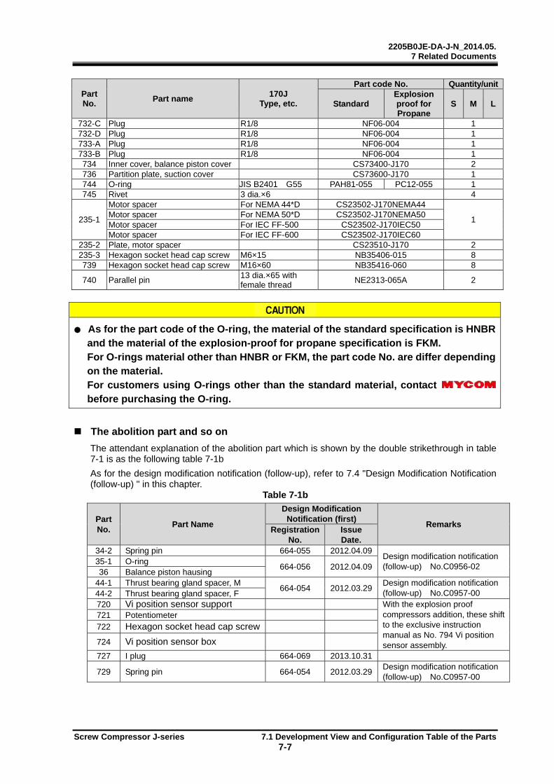
2205B0JE-DA-J-N_2014.05. 7 Related Documents
Screw Compressor J-series 7.1 Development View and Configuration Table of the Parts 7-7
Part No.
Part name 170J
Type, etc.
Part code No. Quantity/unit
Standard Explosion proof for Propane
S M L
732-C Plug R1/8 NF06-004 1 732-D Plug R1/8 NF06-004 1 733-A Plug R1/8 NF06-004 1 733-B Plug R1/8 NF06-004 1 734 Inner cover, balance piston cover CS73400-J170 2 736 Partition plate, suction cover CS73600-J170 1 744 O-ring JIS B2401 G55 PAH81-055 PC12-055 1745 Rivet 3 dia.×6 4
235-1
Motor spacer For NEMA 44*D CS23502-J170NEMA44
1 Motor spacer For NEMA 50*D CS23502-J170NEMA50 Motor spacer For IEC FF-500 CS23502-J170IEC50 Motor spacer For IEC FF-600 CS23502-J170IEC60
235-2 Plate, motor spacer CS23510-J170 2 235-3 Hexagon socket head cap screw M6×15 NB35406-015 8 739 Hexagon socket head cap screw M16×60 NB35416-060 8
740 Parallel pin 13 dia.×65 with female thread
NE2313-065A 2
As for the part code of the O-ring, the material of the standard specification is HNBR and the material of the explosion-proof for propane specification is FKM. For O-rings material other than HNBR or FKM, the part code No. are differ depending on the material. For customers using O-rings other than the standard material, contact before purchasing the O-ring.
The abolition part and so on
The attendant explanation of the abolition part which is shown by the double strikethrough in table 7-1 is as the following table 7-1b As for the design modification notification (follow-up), refer to 7.4 "Design Modification Notification (follow-up) " in this chapter. Table 7-1b
Part No.
Part Name
Design Modification Notification (first)
Remarks Registration
No. Issue Date.
34-2 Spring pin 664-055 2012.04.09Design modification notification (follow-up) No.C0956-02
35-1 O-ring 664-056 2012.04.09
36 Balance piston hausing 44-1 Thrust bearing gland spacer, M
664-054 2012.03.29Design modification notification (follow-up) No.C0957-00 44-2 Thrust bearing gland spacer, F
720 Vi position sensor support With the explosion proof compressors addition, these shift to the exclusive instruction manual as No. 794 Vi position sensor assembly.
721 Potentiometer 722 Hexagon socket head cap screw
724 Vi position sensor box
727 I plug 664-069 2013.10.31
729 Spring pin 664-054 2012.03.29Design modification notification (follow-up) No.C0957-00
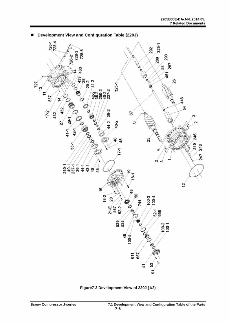
2205B0JE-DA-J-N_2014.05. 7 Related Documents
Screw Compressor J-series 7.1 Development View and Configuration Table of the Parts 7-8
Development View and Configuration Table (220J)
Figure7-3 Development View of 220J (1/2)
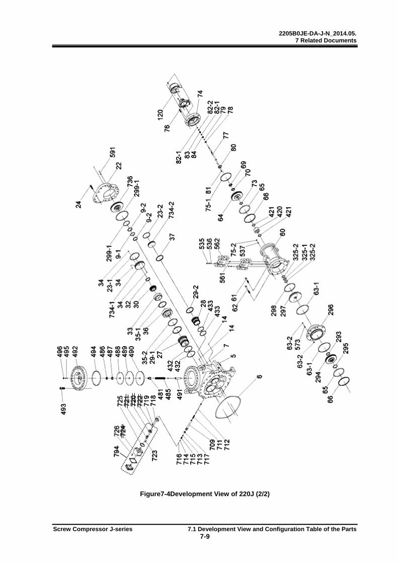
2205B0JE-DA-J-N_2014.05. 7 Related Documents
Screw Compressor J-series 7.1 Development View and Configuration Table of the Parts 7-9
Figure7-4Development View of 220J (2/2)
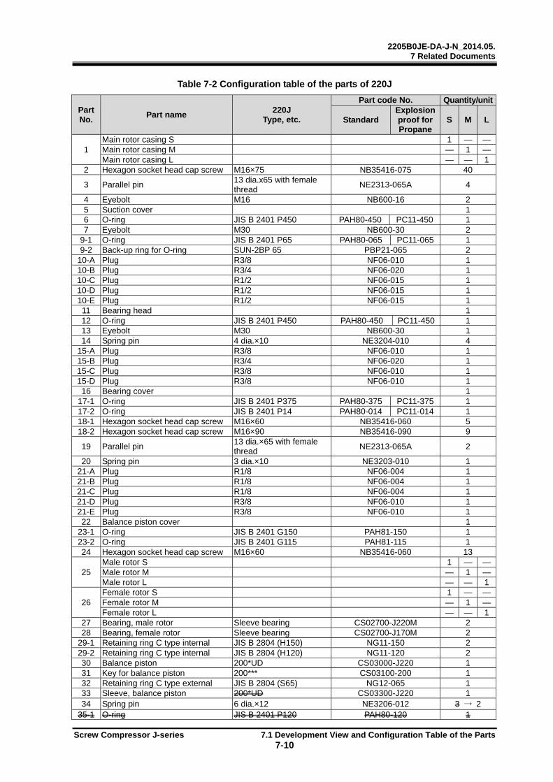
2205B0JE-DA-J-N_2014.05. 7 Related Documents
Screw Compressor J-series 7.1 Development View and Configuration Table of the Parts 7-10
Table 7-2 Configuration table of the parts of 220J
Part No.
Part name 220J
Type, etc.
Part code No. Quantity/unit
Standard Explosion proof for Propane
S M L
1 Main rotor casing S 1 — —Main rotor casing M — 1 —Main rotor casing L — — 1
2 Hexagon socket head cap screw M16×75 NB35416-075 40
3 Parallel pin 13 dia.x65 with female thread
NE2313-065A 4
4 Eyebolt M16 NB600-16 2 5 Suction cover 1 6 O-ring JIS B 2401 P450 PAH80-450 PC11-450 1 7 Eyebolt M30 NB600-30 2
9-1 O-ring JIS B 2401 P65 PAH80-065 PC11-065 1 9-2 Back-up ring for O-ring SUN-2BP 65 PBP21-065 2
10-A Plug R3/8 NF06-010 1 10-B Plug R3/4 NF06-020 1 10-C Plug R1/2 NF06-015 1 10-D Plug R1/2 NF06-015 1 10-E Plug R1/2 NF06-015 1 11 Bearing head 1 12 O-ring JIS B 2401 P450 PAH80-450 PC11-450 1 13 Eyebolt M30 NB600-30 1 14 Spring pin 4 dia.×10 NE3204-010 4
15-A Plug R3/8 NF06-010 1 15-B Plug R3/4 NF06-020 1 15-C Plug R3/8 NF06-010 1 15-D Plug R3/8 NF06-010 1 16 Bearing cover 1
17-1 O-ring JIS B 2401 P375 PAH80-375 PC11-375 1 17-2 O-ring JIS B 2401 P14 PAH80-014 PC11-014 1 18-1 Hexagon socket head cap screw M16×60 NB35416-060 5 18-2 Hexagon socket head cap screw M16×90 NB35416-090 9
19 Parallel pin 13 dia.×65 with female thread
NE2313-065A 2
20 Spring pin 3 dia.×10 NE3203-010 1 21-A Plug R1/8 NF06-004 1 21-B Plug R1/8 NF06-004 1 21-C Plug R1/8 NF06-004 1 21-D Plug R3/8 NF06-010 1 21-E Plug R3/8 NF06-010 1 22 Balance piston cover 1
23-1 O-ring JIS B 2401 G150 PAH81-150 1 23-2 O-ring JIS B 2401 G115 PAH81-115 1 24 Hexagon socket head cap screw M16×60 NB35416-060 13
25 Male rotor S 1 — —Male rotor M — 1 —Male rotor L — — 1
26 Female rotor S 1 — —Female rotor M — 1 —Female rotor L — — 1
27 Bearing, male rotor Sleeve bearing CS02700-J220M 2 28 Bearing, female rotor Sleeve bearing CS02700-J170M 2
29-1 Retaining ring C type internal JIS B 2804 (H150) NG11-150 2 29-2 Retaining ring C type internal JIS B 2804 (H120) NG11-120 2 30 Balance piston 200*UD CS03000-J220 1 31 Key for balance piston 200*** CS03100-200 1 32 Retaining ring C type external JIS B 2804 (S65) NG12-065 1 33 Sleeve, balance piston 200*UD CS03300-J220 1 34 Spring pin 6 dia.×12 NE3206-012 3 → 2
35-1 O-ring JIS B 2401 P120 PAH80-120 1

2205B0JE-DA-J-N_2014.05. 7 Related Documents
Screw Compressor J-series 7.1 Development View and Configuration Table of the Parts 7-11
Part No.
Part name 220J
Type, etc.
Part code No. Quantity/unit
Standard Explosion proof for Propane
S M L
35-2 O-ring JIS B 2401 G150 PAH81-150 PC12-150 1 36 Housing, balance piston CS03600-J220 1 37 Retaining ring C type internal JIS B 2804 (H120) NG11-120 1
38-1 Thrust bearing assembly, male rotor
7316BEAXT7DF CS03800-J220M 1
38-2 Thrust bearing assembly, female rotor
7312BEAXT7DF CS03800-J170M 1
39-1 Locknut AN16 NG31-016 1 39-2 Locknut AN12 NG31-012 1 40-1 Lock washer AW16 NG32-016 1 40-2 Lock washer AW12 NG32-012 1
41-1 Thrust bearing outer race spacer, male rotor
CS04100-J220M 1
41-2 Thrust bearing outer race spacer, female rotor
CS04100-J220F 1
42-1 Thrust bearing alignment spacer, male rotor
CS04200-J220M 1
42-2 Thrust bearing alignment spacer, female rotor
Spacer, alignment male rotor for 170J*
CS04200-J170M 1
43-1 Thrust bearing gland, male rotor CS04300-J220M 1 43-2 Thrust bearing gland, female rotor CS04300-J220F 1 44-1 Thrust bearing gland spacer, male rotor CS04400-J220M 1 44-2 Thrust bearing gland spacer, female rotor CS04400-J220F 1 45 Hexagon head screw M12×50 NB111012-050 12
46 Conical spring washer Hexagon head screw M12
ND320-012 12
48 Retainer for oil seal CS04800-J220 1 49 O-ring JIS B 2401 G145 PAH81-145 PC12-145 1 50 Oil seal SA1J 75 100 13 CS05010-250VD 1 51 Seal cover 1
52-1 O-ring JIS B 2401 G145 PAH81-145 PC12-145 1 52-2 O-ring JIS B 2401 P14 PAH80-014 PC11-014 1 53 Hexagon socket head cap screw M10×35 NB35410-035 8
54 Unloader slide valve S 1 — —Unloader slide valve M — 1 —Unloader slide valve L — — 1
58 Hexagon socket head cap screw M8×35 NB35408-035 9 60 Unloader cylinder 1 61 Hexagon socket head cap screw M16×90 NB35416-090 2 62 Hexagon socket head cap screw M16×140 NB35416-140 6
63-1 O-ring JIS B2401 G200 PAH81-200 PC12-200 2 63-2 O-ring JIS B2401 P14 PAH80-014 PC11-014 2 64 Unloader piston CS06400-J220 1 65 O-ring JIS B2401 P170 PAH80-170 PC11-170 2 66 Teflon cap seal SUNR-BE-170 CS06600-J220 2 67 Push rod, unloader slide valve CS06700-J220 1 68 Guide pin PH01NG 5×12 BK NE2505-012 1 69 Locknut AN07 NG31-007 1 70 Lock washer AW07 NG32-007 1 73 O-ring JIS B2401 P44 PAH80-044 PC11-044 1 74 Unloader cylinder cover 1
75-1 O-ring JIS B2401 G175 PAH81-175 PC12-175 1 75-2 O-ring JIS B2401 P14 PAH80-014 PC11-014 1 76 Hexagon socket head cap screw M12×50 NB35412-050 8
77 Unloader indicator cam S CS07700-J220S 1 — —Unloader indicator cam M CS07700-J220M — 1 —Unloader indicator cam L CS07700-J220L — — 1
78 Ball bearing #6000 CS07800-200 1 79 Retaining ring C type external JISB2804 (S10) NG12-010 1 80 Bearing gland CS08000-200 1
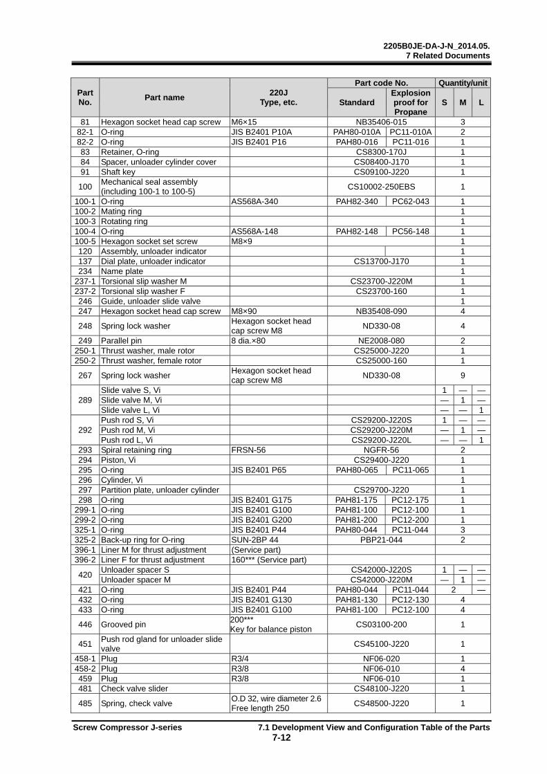
2205B0JE-DA-J-N_2014.05. 7 Related Documents
Screw Compressor J-series 7.1 Development View and Configuration Table of the Parts 7-12
Part No.
Part name 220J
Type, etc.
Part code No. Quantity/unit
Standard Explosion proof for Propane
S M L
81 Hexagon socket head cap screw M6×15 NB35406-015 3 82-1 O-ring JIS B2401 P10A PAH80-010A PC11-010A 2 82-2 O-ring JIS B2401 P16 PAH80-016 PC11-016 1 83 Retainer, O-ring CS8300-170J 1 84 Spacer, unloader cylinder cover CS08400-J170 1 91 Shaft key CS09100-J220 1
100 Mechanical seal assembly (including 100-1 to 100-5)
CS10002-250EBS 1
100-1 O-ring AS568A-340 PAH82-340 PC62-043 1 100-2 Mating ring 1 100-3 Rotating ring 1 100-4 O-ring AS568A-148 PAH82-148 PC56-148 1 100-5 Hexagon socket set screw M8×9 1 120 Assembly, unloader indicator 1 137 Dial plate, unloader indicator CS13700-J170 1 234 Name plate 1
237-1 Torsional slip washer M CS23700-J220M 1 237-2 Torsional slip washer F CS23700-160 1 246 Guide, unloader slide valve 1 247 Hexagon socket head cap screw M8×90 NB35408-090 4
248 Spring lock washer Hexagon socket head cap screw M8
ND330-08 4
249 Parallel pin 8 dia.×80 NE2008-080 2 250-1 Thrust washer, male rotor CS25000-J220 1 250-2 Thrust washer, female rotor CS25000-160 1
267 Spring lock washer Hexagon socket head cap screw M8
ND330-08 9
289 Slide valve S, Vi 1 — —Slide valve M, Vi — 1 —Slide valve L, Vi — — 1
292 Push rod S, Vi CS29200-J220S 1 — —Push rod M, Vi CS29200-J220M — 1 —Push rod L, Vi CS29200-J220L — — 1
293 Spiral retaining ring FRSN-56 NGFR-56 2 294 Piston, Vi CS29400-J220 1 295 O-ring JIS B2401 P65 PAH80-065 PC11-065 1 296 Cylinder, Vi 1 297 Partition plate, unloader cylinder CS29700-J220 1 298 O-ring JIS B2401 G175 PAH81-175 PC12-175 1
299-1 O-ring JIS B2401 G100 PAH81-100 PC12-100 1 299-2 O-ring JIS B2401 G200 PAH81-200 PC12-200 1 325-1 O-ring JIS B2401 P44 PAH80-044 PC11-044 3 325-2 Back-up ring for O-ring SUN-2BP 44 PBP21-044 2 396-1 Liner M for thrust adjustment (Service part) 396-2 Liner F for thrust adjustment 160*** (Service part)
420 Unloader spacer S CS42000-J220S 1 — —Unloader spacer M CS42000-J220M — 1 —
421 O-ring JIS B2401 P44 PAH80-044 PC11-044 2 —432 O-ring JIS B2401 G130 PAH81-130 PC12-130 4 433 O-ring JIS B2401 G100 PAH81-100 PC12-100 4
446 Grooved pin 200*** Key for balance piston
CS03100-200 1
451 Push rod gland for unloader slide valve
CS45100-J220 1
458-1 Plug R3/4 NF06-020 1 458-2 Plug R3/8 NF06-010 4 459 Plug R3/8 NF06-010 1 481 Check valve slider CS48100-J220 1
485 Spring, check valve O.D 32, wire diameter 2.6Free length 250
CS48500-J220 1

2205B0JE-DA-J-N_2014.05. 7 Related Documents
Screw Compressor J-series 7.1 Development View and Configuration Table of the Parts 7-13
Part No.
Part name 220J
Type, etc.
Part code No. Quantity/unit
Standard Explosion proof for Propane
S M L
486 Locknut FU nut FU05SS NG42-05 1
487 Plain washer JIS B 1256, normal, product grade C, M24
ND110-24 1
488 Sheet stopper CS48800-J220 1 489 Valve sheet CS48900-J220 1 490 Valve disc CS49000-J220 1 491 Check valve stem CS49100-J220 1 492 Suction adapter 1 493 Hexagon socket head cap screw M22×60 NB35422-060 12 494 O-ring JIS B2401 P220 PAH80-220 PC11-220 1 495 Check valve stem gland CS49500-J220 1 496 Plain washer JIS B1256, normal M12 1 497 Hexagon nut M12 NC30-12 1 528 Sleeve, oil seal 250*** CS52800-250VD 1 529 Hexagon socket set screw M6×8 NA83606-008 2 535 Hexagon socket head cap screw M5×75 NB35405-075 8
536 Spring lock washer Hexagon socket head cap screw M5
ND330-05 8
537 Bush, P14 type O-ring CS53700-J170 4 561 O-ring JISB2401 P12 PAH80-012 PC11-012 8
562 Capacity control / variable Vi solenoid valve
SBL5B-4BL (UL,CSA) KK425-1/2/3 - 2 SXL6-4BL (CE) -
Dummy block, solenoid valve with bushing -
591 Parallel pin 16 dia.×55 with female thread
NE2313-065A 2
605 Plug R1/2 NF06-015 1 607-A Plug R1/8 NF06-004 1 607-B Plug R1/8 NF06-004 1 607-C Plug R1/8 NF06-004 1
611 Sleeve, shower flashing CS61100-J220 1 657 O-ring JIS B2401 G120 PAH81-120 PC12-120 1 658 Retaining ring C type internal JIS B2804 (H120) NG11-120 1 709 Vi position sensor rod housing CS70900-J220 1
711 Spring O.D 13, wire diameter 1.6Free length 100
CS71100-J170 1
712 Vi position sensor rod CS71200-J220 1 713 O-ring JIS B2401 P12 PAH80-012 PC11-012 1 714 O-ring JIS B2401 P6 PAH80-006 PC11-006 1 715 Plug, Vi position sensor rod CS71500-J170 1 716 Retaining ring E type JIS B2804 E snap ring 4 NG13-004 1 717 O-ring JIS B2401 G25 PAH81-025 PC12-025 1
718 Gland, Vi position sensor rod housing
CS71800-J170 1
719 Hexagon socket head cap screw M6×25 NB35406-025 4 720 Vi position sensor support CS72000-J170 1
721 Potentiometer Midori Precisions LP-10FB
CS12907-J1701 1
722 Hexagon socket head cap screw M3×10 NB35403-010 2 723 Hexagon socket head cap screw M6×25 NB35406-025 2 724 Vi position sensor box 1 725 Packing, Sensor box 1 726 Hexagon socket head cap screw M5×15 NB35405-015 4 794 Vi position sensor assembly 1 727 I plug CS72700-J170 1
728-1 E plug CS72810-J220 1 728-2 E plug gland CS72820-J220 1 728-3 E plug flange CS72830-J220 1 728-4 O-ring JIS B2401 G45 PAH81-045 PC12-045 1 728-5 Hexagon head screw M16×45 NB111016-045 2
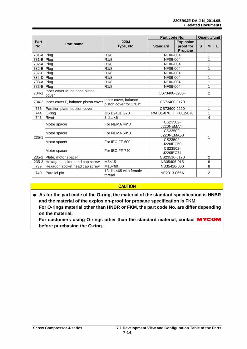
2205B0JE-DA-J-N_2014.05. 7 Related Documents
Screw Compressor J-series 7.1 Development View and Configuration Table of the Parts 7-14
Part No.
Part name 220J
Type, etc.
Part code No. Quantity/unit
Standard Explosion proof for Propane
S M L
731-A Plug R1/8 NF06-004 1 731-B Plug R1/8 NF06-004 1 732-A Plug R1/8 NF06-004 1 732-B Plug R1/8 NF06-004 1 732-C Plug R1/8 NF06-004 1 732-D Plug R1/8 NF06-004 1 733-A Plug R1/8 NF06-004 1 733-B Plug R1/8 NF06-004 1
734-1 Inner cover M, balance piston cover
CS73400-J280F 2
734-2 Inner cover F, balance piston coverInner cover, balance piston cover for 170J*
CS73400-J170 1
736 Partition plate, suction cover CS73600-J220 1 744 O-ring JIS B2401 G70 PAH81-070 PC12-070 1 745 Rivet 3 dia.×6 4
235-1
Motor spacer For NEMA 44*D CS23502-
J220NEMA44
1 Motor spacer For NEMA 50*D
CS23502- J220NEMA50
Motor spacer For IEC FF-600 CS23502- J220IEC60
Motor spacer For IEC FF-740 CS23502- J220IEC74
235-2 Plate, motor spacer CS23510-J170 2 235-3 Hexagon socket head cap screw M6×15 NB35406-015 8 739 Hexagon socket head cap screw M16×60 NB35416-060 8
740 Parallel pin 13 dia.×65 with female thread
NE2313-065A 2
As for the part code of the O-ring, the material of the standard specification is HNBR and the material of the explosion-proof for propane specification is FKM. For O-rings material other than HNBR or FKM, the part code No. are differ depending on the material. For customers using O-rings other than the standard material, contact before purchasing the O-ring.
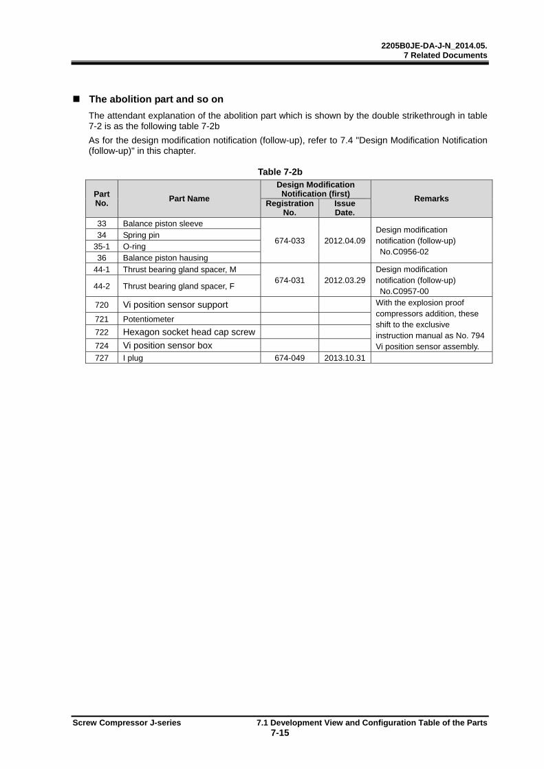
2205B0JE-DA-J-N_2014.05. 7 Related Documents
Screw Compressor J-series 7.1 Development View and Configuration Table of the Parts 7-15
The abolition part and so on
The attendant explanation of the abolition part which is shown by the double strikethrough in table 7-2 is as the following table 7-2b As for the design modification notification (follow-up), refer to 7.4 "Design Modification Notification (follow-up)" in this chapter. Table 7-2b
Part No. Part Name
Design Modification Notification (first)
Remarks Registration
No. Issue Date.
33 Balance piston sleeve
674-033 2012.04.09Design modification notification (follow-up) No.C0956-02
34 Spring pin 35-1 O-ring 36 Balance piston hausing
44-1 Thrust bearing gland spacer, M 674-031 2012.03.29
Design modification notification (follow-up) No.C0957-00
44-2 Thrust bearing gland spacer, F
720 Vi position sensor support With the explosion proof compressors addition, these shift to the exclusive instruction manual as No. 794 Vi position sensor assembly.
721 Potentiometer
722 Hexagon socket head cap screw
724 Vi position sensor box
727 I plug 674-049 2013.10.31

2205B0JE-DA-J-N_2014.05. 7 Related Documents
Screw Compressor J-series 7.1 Development View and Configuration Table of the Parts 7-16
Development View and Configuration Table (280J)
Figure7-5 Development View of 280J (1/2)

2205B0JE-DA-J-N_2014.05. 7 Related Documents
Screw Compressor J-series 7.1 Development View and Configuration Table of the Parts 7-17
Figure7-6Development View of 280J (2/2)
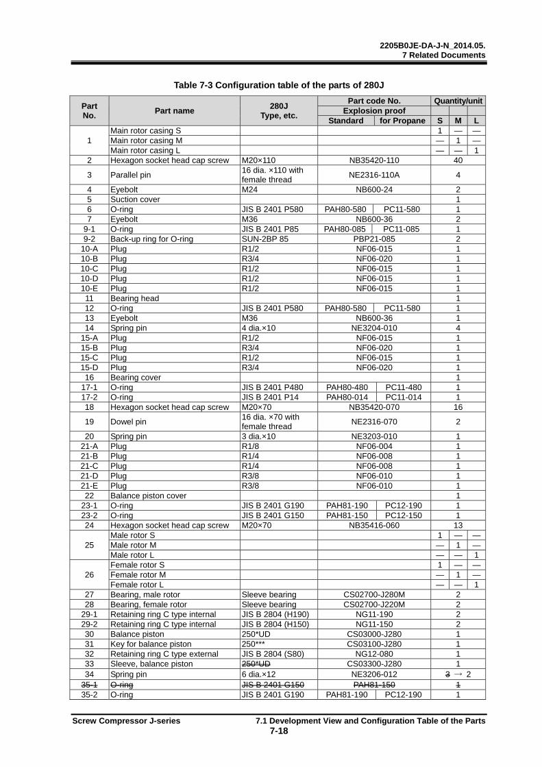
2205B0JE-DA-J-N_2014.05. 7 Related Documents
Screw Compressor J-series 7.1 Development View and Configuration Table of the Parts 7-18
Table 7-3 Configuration table of the parts of 280J
Part No.
Part name 280J
Type, etc.
Part code No. Quantity/unitExplosion proof
Standard for Propane S M L
1 Main rotor casing S 1 — —Main rotor casing M — 1 —Main rotor casing L — — 1
2 Hexagon socket head cap screw M20×110 NB35420-110 40
3 Parallel pin 16 dia. ×110 with female thread
NE2316-110A 4
4 Eyebolt M24 NB600-24 2 5 Suction cover 1 6 O-ring JIS B 2401 P580 PAH80-580 PC11-580 1 7 Eyebolt M36 NB600-36 2
9-1 O-ring JIS B 2401 P85 PAH80-085 PC11-085 1 9-2 Back-up ring for O-ring SUN-2BP 85 PBP21-085 2
10-A Plug R1/2 NF06-015 1 10-B Plug R3/4 NF06-020 1 10-C Plug R1/2 NF06-015 1 10-D Plug R1/2 NF06-015 1 10-E Plug R1/2 NF06-015 1 11 Bearing head 1 12 O-ring JIS B 2401 P580 PAH80-580 PC11-580 1 13 Eyebolt M36 NB600-36 1 14 Spring pin 4 dia.×10 NE3204-010 4
15-A Plug R1/2 NF06-015 1 15-B Plug R3/4 NF06-020 1 15-C Plug R1/2 NF06-015 1 15-D Plug R3/4 NF06-020 1 16 Bearing cover 1
17-1 O-ring JIS B 2401 P480 PAH80-480 PC11-480 1 17-2 O-ring JIS B 2401 P14 PAH80-014 PC11-014 1 18 Hexagon socket head cap screw M20×70 NB35420-070 16
19 Dowel pin 16 dia. ×70 with female thread
NE2316-070 2
20 Spring pin 3 dia.×10 NE3203-010 1 21-A Plug R1/8 NF06-004 1 21-B Plug R1/4 NF06-008 1 21-C Plug R1/4 NF06-008 1 21-D Plug R3/8 NF06-010 1 21-E Plug R3/8 NF06-010 1 22 Balance piston cover 1
23-1 O-ring JIS B 2401 G190 PAH81-190 PC12-190 1 23-2 O-ring JIS B 2401 G150 PAH81-150 PC12-150 1 24 Hexagon socket head cap screw M20×70 NB35416-060 13
25 Male rotor S 1 — —Male rotor M — 1 —Male rotor L — — 1
26 Female rotor S 1 — —Female rotor M — 1 —Female rotor L — — 1
27 Bearing, male rotor Sleeve bearing CS02700-J280M 2 28 Bearing, female rotor Sleeve bearing CS02700-J220M 2
29-1 Retaining ring C type internal JIS B 2804 (H190) NG11-190 2 29-2 Retaining ring C type internal JIS B 2804 (H150) NG11-150 2 30 Balance piston 250*UD CS03000-J280 1 31 Key for balance piston 250*** CS03100-J280 1 32 Retaining ring C type external JIS B 2804 (S80) NG12-080 1 33 Sleeve, balance piston 250*UD CS03300-J280 1 34 Spring pin 6 dia.×12 NE3206-012 3 → 2
35-1 O-ring JIS B 2401 G150 PAH81-150 1 35-2 O-ring JIS B 2401 G190 PAH81-190 PC12-190 1

2205B0JE-DA-J-N_2014.05. 7 Related Documents
Screw Compressor J-series 7.1 Development View and Configuration Table of the Parts 7-19
Part No.
Part name 280J
Type, etc.
Part code No. Quantity/unitExplosion proof
Standard for Propane S M L36 Housing, balance piston CS03600-J280 1
38-1 Thrust bearing assembly, male rotor
7320BEAXT7DF CS03800-J280M 1
38-2 Thrust bearing assembly, female rotor
7316BEAXT7DF CS03800-J220M 1
39-1 Locknut AN20 NG31-020 1 39-2 Locknut AN16 NG31-016 1 40-1 Lock washer AW20 NG32-020 1 40-2 Lock washer AW16 NG32-016 1
42-1 Thrust bearing alignment spacer, male rotor
CS04200-J280M 1
42-2 Thrust bearing alignment spacer, female rotor
CS04200-J220M 1
43-1 Thrust bearing gland, male rotor CS04300-J280M 1 43-2 Thrust bearing gland, female rotor CS04300-J280F 1 44-1 Thrust bearing gland spacer, male rotor CS04400-J280M 1 44-2 Thrust bearing gland spacer, female rotor CS04400-J280F 1 45 Hexagon head screw M16×65 NB111016-065 12
46 Conical spring washer Hexagon head screw M16
ND320-016 12
48 Retainer for oil seal CS04800-J280 1 49 O-ring JIS B 2401 G165 PAH81-165 PC12-165 1 50 Oil seal SA1J 95 120 13 CS05010-320VD 1 51 Seal cover 1
52-1 O-ring JIS B 2401 G165 PAH81-165 PC12-165 1 52-2 O-ring JIS B 2401 P14 PAH80-014 PC11-014 1 53 Hexagon socket head cap screw M12×40 NB35412-040 8
54 Unloader slide valve S 1 — —Unloader slide valve M — 1 —Unloader slide valve L — — 1
58 Hexagon socket head cap screw M10×40 NB35410-040 9 60 Unloader cylinder 1 61 Hexagon socket head cap screw M20×110 NB35420-110 2 62 Hexagon socket head cap screw M20×170 NB35420-170 6 63 O-ring JIS B2401 G260 PAH81-260 PC12-260 2 64 Unloader piston CS06400-J280 1 65 O-ring JIS B2401 P225 PAH80-225 PC11-225 2 66 Teflon cap seal SUNR-BE-225 CS06600-J280 2 67 Push rod, unloader slide valve CS06700-J280 1
68 Guide pin PH01NG 6×16 BK
NE2506-016 1
69 Locknut AN09 NG31-009 1 70 Lock washer AW09 NG32-009 1 73 O-ring JIS B2401 P58 PAH80-058 PC11-058 1 74 Unloader cylinder cover 1 75 O-ring JIS B2401 G230 PAH81-230 PC12-230 1 76 Hexagon socket head cap screw M16×60 NB35416-060 8
77 Unloader indicator cam S CS07700-J280S 1 — —Unloader indicator cam M CS07700-J280M — 1 —Unloader indicator cam L CS07700-J280L — — 1
78 Ball bearing #6000 CS07800-200 1 79 Retaining ring C type external JISB2804 (S10) NG12-010 1 80 Bearing gland CS08000-200 1 81 Hexagon socket head cap screw M6×15 NB35406-015 3
82-1 O-ring JIS B2401 P10A PAH80-010A PC11-010A 2 82-2 O-ring JIS B2401 P16 PAH80-016 PC11-016 1 83 Retainer, O-ring CS08300-J170 1 84 Spacer, unloader cylinder cover CS08400-J170 1 91 Shaft key CS09100-J280 1
100 Mechanical seal assembly (including 100-1 to 100-5)
CS10002-320EBS 1
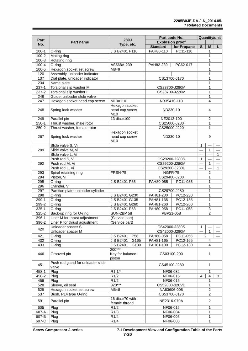
2205B0JE-DA-J-N_2014.05. 7 Related Documents
Screw Compressor J-series 7.1 Development View and Configuration Table of the Parts 7-20
Part No.
Part name 280J
Type, etc.
Part code No. Quantity/unitExplosion proof
Standard for Propane S M L100-1 O-ring JIS B2401 P110 PAH80-110 PC11-110 1 100-2 Mating ring 1 100-3 Rotating ring 1 100-4 O-ring AS568A-239 PAH82-239 PC62-017 1 100-5 Hexagon socket set screw M8×9 1 120 Assembly, unloader indicator 1 137 Dial plate, unloader indicator CS13700-J170 1 234 Name plate 1
237-1 Torsional slip washer M CS23700-J280M 1 237-2 Torsional slip washer F CS23700-J220M 1 246 Guide, unloader slide valve 1 247 Hexagon socket head cap screw M10×110 NB35410-110 4
248 Spring lock washer Hexagon socket head cap screw M10
ND330-10 4
249 Parallel pin 13 dia.×100 NE2013-100 2 250-1 Thrust washer, male rotor CS25000-J280 1 250-2 Thrust washer, female rotor CS25000-J220 1
267 Spring lock washer Hexagon socket head cap screw M10
ND330-10 9
289 Slide valve S, Vi 1 — —Slide valve M, Vi — 1 —Slide valve L, Vi — — 1
292 Push rod S, Vi CS29200-J280S 1 — —Push rod M, Vi CS29200-J280M — 1 —Push rod L, Vi CS29200-J280L — — 1
293 Spiral retaining ring FRSN-75 NGFR-75 2 294 Piston, Vi CS29400-J280 1 295 O-ring JIS B2401 P85 PAH80-085 PC11-085 1 296 Cylinder, Vi 1 297 Partition plate, unloader cylinder CS29700-J280 1 298 O-ring JIS B2401 G230 PAH81-230 PC12-230 1
299-1 O-ring JIS B2401 G135 PAH81-135 PC12-135 1 299-2 O-ring JIS B2401 G260 PAH81-260 PC12-260 1 325-1 O-ring JIS B2401 P58 PAH80-058 PC11-058 3 325-2 Back-up ring for O-ring SUN-2BP 58 PBP21-058 2 396-1 Liner M for thrust adjustment (Service part) 396-2 Liner F for thrust adjustment (Service part)
420 Unloader spacer S CS42000-J280S 1 — —Unloader spacer M CS42000-J280M — 1 —
421 O-ring JIS B2401 P58 PAH80-058 PC11-058 2 —432 O-ring JIS B2401 G165 PAH81-165 PC12-165 4 433 O-ring JIS B2401 G130 PAH81-130 PC12-130 4
446 Grooved pin 200*** Key for balance piston
CS03100-200 1
451 Push rod gland for unloader slide valve
CS45100-J280 1
458-1 Plug R1 1/4 NF06-032 1 458-2 Plug R1/2 NF06-015 4 4 3459 Plug R1/2 NF06-015 1 528 Sleeve, oil seal 320*** CS52800-320VD 1 529 Hexagon socket set screw M6×8 NA83606-008 2 537 Bush, P14 type O-ring CS53700-J170 2
591 Parallel pin 16 dia.×70 with female thread
NE2316-070A 2
605 Plug R1/2 NF06-015 1 607-A Plug R1/8 NF06-004 1 607-B Plug R1/4 NF06-008 1 607-C Plug R1/4 NF06-008 1

2205B0JE-DA-J-N_2014.05. 7 Related Documents
Screw Compressor J-series 7.1 Development View and Configuration Table of the Parts 7-21
Part No.
Part name 280J
Type, etc.
Part code No. Quantity/unitExplosion proof
Standard for Propane S M L611 Sleeve, shower flashing 1 657 O-ring JIS B2401 G140 PAH81-140 PC12-140 1 658 Retaining ring JIS B2804 H140 NG11-140 1 709 Vi position sensor rod housing CS70900-J280 1
711 Spring O.D 13, wire diameter 1.6 Free length 100
CS71100-J170 1
712 Vi position sensor rod CS71200-J280 1 713 O-ring JIS B2401 P12 PAH80-012 PC11-140 1 714 O-ring JIS B2401 P6 PAH80-006 PC11-006 1 715 Plug, Vi position sensor rod CS71500-J170 1
716 Retaining ring JIS B2804 E snap ring 4
NG13-004 1
717 O-ring JIS B2401 G25 PAH81-025 PC12-025 1
718 Gland, Vi position sensor rod housing
CS71800-J170 1
719 Hexagon socket head cap screw M6×25 NB35406-025 4 720 Vi position sensor support CS72000-J170 1
721 Potentiometer Midori Precisions LP-10FB
CS12907-J1701 1
722 Hexagon socket head cap screw M3×10 NB35403-010 2 723 Hexagon socket head cap screw M6×25 NB35406-025 2 724 Vi position sensor box 1 725 Packing, Sensor box 1 726 Hexagon socket head cap screw M5×15 NB35405-015 4 794 Vi position sensor assembly 1 727 I plug 170J* E plug CS72700-J170 1
728-1 E plug CS72810-J280 1 728-2 E plug gland CS72820-J280 1 728-3 E plug flange CS72830-J280 1 728-4 O-ring JIS B2401 G65 PAH81-065 PC12-065 1 728-5 Hexagon head screw M16×45 NB111016-045 2 731-A Plug R1/4 NF06-008 1 731-B Plug R1/4 NF06-008 1 731-C Plug R1/8 NF06-004 1 732-A Plug R1/2 NF06-015 1 732-B Plug R1/2 NF06-015 1 733 Plug R1/2 NF06-015 1
734-1 Inner cover M, balance piston cover
CS73400-J280M 1
734-2 Inner cover F, balance piston coverInner cover, balance piston cover for 220J*
CS73400-J280F 1
736 Partition plate, suction cover CS73600-J280 1 744 O-ring JIS B2401 G90 PAH81-090 PC12-090 1 745 Rivet 3 dia.×6 4
As for the part code of the O-ring, the material of the explosion-proof for standard specification is HNBR and the material of the explosion-proof for propane specification is FKM. For O-rings material other than HNBR or FKM, the part code No. are differ depending on the material. For customers using O-rings other than the standard material, contact before purchasing the O-ring.
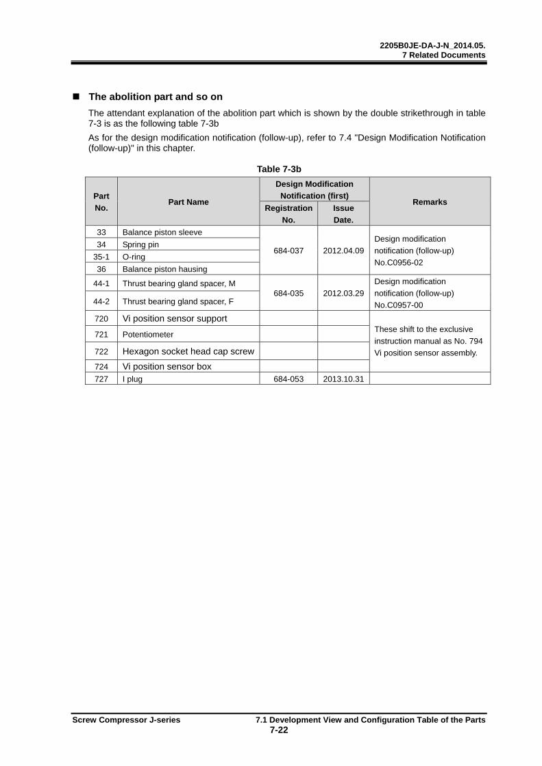
2205B0JE-DA-J-N_2014.05. 7 Related Documents
Screw Compressor J-series 7.1 Development View and Configuration Table of the Parts 7-22
The abolition part and so on
The attendant explanation of the abolition part which is shown by the double strikethrough in table 7-3 is as the following table 7-3b As for the design modification notification (follow-up), refer to 7.4 "Design Modification Notification (follow-up)" in this chapter. Table 7-3b
Part
No. Part Name
Design Modification
Notification (first) Remarks
Registration
No.
Issue
Date.
33 Balance piston sleeve
684-037 2012.04.09
Design modification
notification (follow-up)
No.C0956-02
34 Spring pin
35-1 O-ring
36 Balance piston hausing
44-1 Thrust bearing gland spacer, M 684-035 2012.03.29
Design modification
notification (follow-up)
No.C0957-00 44-2 Thrust bearing gland spacer, F
720 Vi position sensor support
These shift to the exclusive
instruction manual as No. 794
Vi position sensor assembly.
721 Potentiometer
722 Hexagon socket head cap screw
724 Vi position sensor box
727 I plug 684-053 2013.10.31
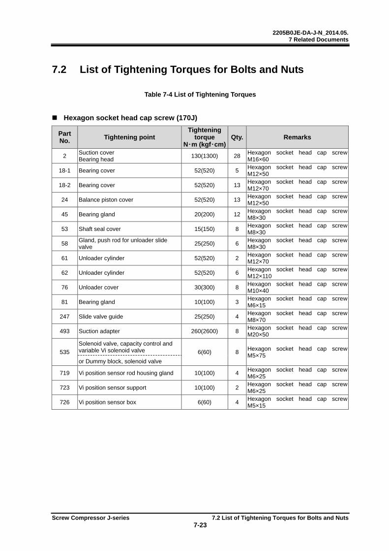
2205B0JE-DA-J-N_2014.05. 7 Related Documents
Screw Compressor J-series 7.2 List of Tightening Torques for Bolts and Nuts 7-23
7.2 List of Tightening Torques for Bolts and Nuts
Table 7-4 List of Tightening Torques
Hexagon socket head cap screw (170J)
Part No. Tightening point
Tightening torque
N・m (kgf・cm)Qty. Remarks
2 Suction cover Bearing head
130(1300) 28Hexagon socket head cap screw M16×60
18-1 Bearing cover 52(520) 5 Hexagon socket head cap screw M12×50
18-2 Bearing cover 52(520) 13Hexagon socket head cap screw M12×70
24 Balance piston cover 52(520) 13Hexagon socket head cap screw M12×50
45 Bearing gland 20(200) 12Hexagon socket head cap screw M8×30
53 Shaft seal cover 15(150) 8 Hexagon socket head cap screw M8×30
58 Gland, push rod for unloader slide valve
25(250) 6 Hexagon socket head cap screw M8×30
61 Unloader cylinder 52(520) 2 Hexagon socket head cap screw M12×70
62 Unloader cylinder 52(520) 6 Hexagon socket head cap screw M12×110
76 Unloader cover 30(300) 8 Hexagon socket head cap screw M10×40
81 Bearing gland 10(100) 3 Hexagon socket head cap screw M6×15
247 Slide valve guide 25(250) 4 Hexagon socket head cap screw M8×70
493 Suction adapter 260(2600) 8 Hexagon socket head cap screw M20×50
535
Solenoid valve, capacity control and variable Vi solenoid valve 6(60) 8
Hexagon socket head cap screw M5×75
or Dummy block, solenoid valve
719 Vi position sensor rod housing gland 10(100) 4 Hexagon socket head cap screw M6×25
723 Vi position sensor support 10(100) 2 Hexagon socket head cap screw M6×25
726 Vi position sensor box 6(60) 4 Hexagon socket head cap screw M5×15

2205B0JE-DA-J-N_2014.05. 7 Related Documents
Screw Compressor J-series 7.2 List of Tightening Torques for Bolts and Nuts 7-24
Hexagon socket head cap screw /Hexagon head screw (220J)
Part No.
Tightening point Tightening
torque N・m (kgf・cm)
Qty. Remarks
2 Suction cover Bearing head
130(1300) 40Hexagon socket head cap screw M16×75
18-1 Bearing cover 130(1300) 5 Hexagon socket head cap screw M16×60
18-2 Bearing cover 130(1300) 9 Hexagon socket head cap screw M16×90
24 Balance piston cover 130(1300) 13Hexagon socket head cap screw M16×60
45 Bearing gland 50(500) 12 Hexagon head screw M12×50
53 Shaft seal cover 30(300) 8 Hexagon socket head cap screw M10×35
58 Gland, push rod for unloader slide valve
25(250) 9 Hexagon socket head cap screw M8×35
61 Unloader cylinder 130(1300) 2 Hexagon socket head cap screw M16×90
62 Unloader cylinder 130(1300) 6 Hexagon socket head cap screw M16×140
76 Unloader cover 52(520) 8 Hexagon socket head cap screw M12×50
81 Bearing gland 10(100) 3 Hexagon socket head cap screw M6×15
247 Slide valve guide 25(250) 4 Hexagon socket head cap screw M8×90
493 Suction adapter 360(3600) 8 Hexagon socket head cap screw M22×60
535
Solenoid valve, capacity control / variable Vi solenoid valve 6(60) 8
Hexagon socket head cap screw M5×75
or Dummy block, solenoid valve
719 Vi position sensor rod housing gland 10(100) 4 Hexagon socket head cap screw M6×25
723 Vi position sensor support 10(100) 2 Hexagon socket head cap screw M6×25
726 Vi position sensor box 6(60) 4 Hexagon socket head cap screw M5×15
728-5 E plug flange 110(1100) 2 Hexagon head screw M16×45

2205B0JE-DA-J-N_2014.05. 7 Related Documents
Screw Compressor J-series 7.2 List of Tightening Torques for Bolts and Nuts 7-25
Hexagon socket head cap screw /Hexagon head screw (280J)
Part No.
Tightening point Tightening
torque N・m (kgf・cm)
Qty. Remarks
2 Suction cover Bearing head
260(2600) 40Hexagon socket head cap screw M20×110
18 Bearing cover 260(2600) 16Hexagon socket head cap screw M20×70
24 Balance piston cover 260(2600) 13Hexagon socket head cap screw M20×70
45 Bearing gland 60(600) 12 Hexagon head screw M16×65
53 Shaft seal cover 52(520) 8 Hexagon socket head cap screw M12×40
58 Gland, push rod for unloader slide valve
50(500) 9 Hexagon socket head cap screw M10×40
61 Unloader cylinder 260(2600) 2 Hexagon socket head cap screw M20×110
62 Unloader cylinder 260(2600) 6 Hexagon socket head cap screw M20×170
76 Unloader cover 130(1300) 8 Hexagon socket head cap screw M16×60
81 Bearing gland 10(100) 3 Hexagon socket head cap screw M6×15
247 Slide valve guide 50(500) 4 Hexagon socket head cap screw M10×110
719 Vi position sensor rod housing gland 10(100) 4 Hexagon socket head cap screw M6×25
723 Vi position sensor support 10(100) 2 Hexagon socket head cap screw M6×25
726 Vi position sensor box 6(60) 4 Hexagon socket head cap screw M5×15
728-5 E plug flange 110(1100) 2 Hexagon head screw M16×45
Hexagon socket
Connection flange taper screw plug
Tightening point
Tightening torque
N・m (kgf・cm) Qty. Remarks
Size
Tighteningtorque
N・m (kgf・cm)
ANSI#300 3/4” 110(1100) 4 Hexagon head screw M16×45 R1/8 15(150)
ANSI#300 1” 110(1100) 4 Hexagon head screw M16×45 R1/4 25(250)
ANSI#300 1 1/4” 110(1100) 4 Hexagon head screw M16×45 R3/8 50(500)
ANSI#300 1 1/2” 140(1400) 4 Hexagon head screw M20×55 R1/2 60(600)
ANSI#300 2 1/2” 140(1400) 8 Hexagon head screw M20×65 R3/4 140(1400)
ANSI#300 3” 140(1400) 8 Hexagon head screw M20×65 R1 180(1800)
ANSI#300 5” 140(1400) 8 Hexagon head screw M20×65 R1 1/4 220(2200)
ANSI#300 8” 240(2400) 12 Hexagon head screw M22×80 R1 1/2 240(2400)
ANSI#300 12” 300(3000) 16 Hexagon head screw M30×100
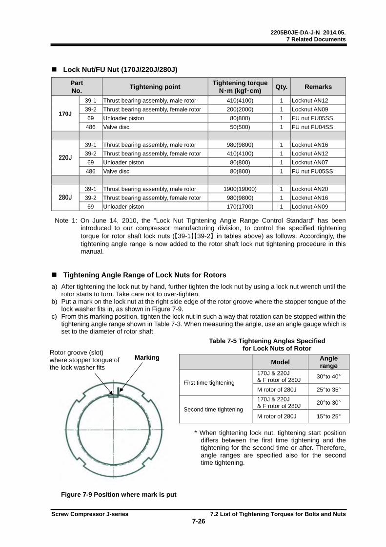
2205B0JE-DA-J-N_2014.05. 7 Related Documents
Screw Compressor J-series 7.2 List of Tightening Torques for Bolts and Nuts 7-26
Lock Nut/FU Nut (170J/220J/280J)
Part No.
Tightening point Tightening torque
N・m (kgf・cm) Qty. Remarks
170J
39-1 Thrust bearing assembly, male rotor 410(4100) 1 Locknut AN12
39-2 Thrust bearing assembly, female rotor 200(2000) 1 Locknut AN09
69 Unloader piston 80(800) 1 FU nut FU05SS
486 Valve disc 50(500) 1 FU nut FU04SS
220J
39-1 Thrust bearing assembly, male rotor 980(9800) 1 Locknut AN16
39-2 Thrust bearing assembly, female rotor 410(4100) 1 Locknut AN12
69 Unloader piston 80(800) 1 Locknut AN07
486 Valve disc 80(800) 1 FU nut FU05SS
280J
39-1 Thrust bearing assembly, male rotor 1900(19000) 1 Locknut AN20
39-2 Thrust bearing assembly, female rotor 980(9800) 1 Locknut AN16
69 Unloader piston 170(1700) 1 Locknut AN09 Note 1: On June 14, 2010, the "Lock Nut Tightening Angle Range Control Standard" has been
introduced to our compressor manufacturing division, to control the specified tightening torque for rotor shaft lock nuts (【39-1】【39-2】 in tables above) as follows. Accordingly, the tightening angle range is now added to the rotor shaft lock nut tightening procedure in this manual.
Tightening Angle Range of Lock Nuts for Rotors
a) After tightening the lock nut by hand, further tighten the lock nut by using a lock nut wrench until the rotor starts to turn. Take care not to over-tighten.
b) Put a mark on the lock nut at the right side edge of the rotor groove where the stopper tongue of the lock washer fits in, as shown in Figure 7-9.
c) From this marking position, tighten the lock nut in such a way that rotation can be stopped within the tightening angle range shown in Table 7-3. When measuring the angle, use an angle gauge which is set to the diameter of rotor shaft.
Table 7-5 Tightening Angles Specified for Lock Nuts of Rotor
* When tightening lock nut, tightening start position differs between the first time tightening and the tightening for the second time or after. Therefore, angle ranges are specified also for the second time tightening.
Figure 7-9 Position where mark is put
Model
Angle range
First time tightening
170J & 220J & F rotor of 280J
30°to 40°
M rotor of 280J 25°to 35°
Second time tightening
170J & 220J & F rotor of 280J
20°to 30°
M rotor of 280J 15°to 25°
Marking Rotor groove (slot) where stopper tongue of the lock washer fits
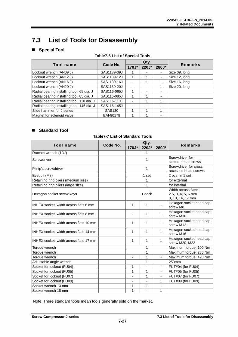
2205B0JE-DA-J-N_2014.05. 7 Related Documents
Screw Compressor J-series 7.3 List of Tools for Disassembly 7-27
7.3 List of Tools for Disassembly
Special Tool Table7-6 List of Special Tools
Tool name Code No. Qty.
Remarks 170J* 220J* 280J*
Locknut wrench (AN09 J) SAS1139-09J 1 - - Size 09, long Locknut wrench (AN12 J) SAS1139-12J 1 1 - Size 12, long Locknut wrench (AN16 J) SAS1139-16J - 1 1 Size 16, long Locknut wrench (AN20 J) SAS1139-20J - - 1 Size 20, long Radial bearing installing tool, 65 dia. J SAS116-065J 1 - - Radial bearing installing tool, 85 dia. J SAS116-085J 1 1 - Radial bearing installing tool, 110 dia. J SAS116-110J - 1 1 Radial bearing installing tool, 145 dia. J SAS116-145J - - 1 Slide hammer for J series SAS130 1 1 1 Magnet for solenoid valve EAI-90178 1 1 -
Standard Tool Table7-7 List of Standard Tools
Tool name Code No. Qty.
Remarks 170J* 220J* 280J*
Ratchet wrench (1/4") 1
Screwdriver 1 Screwdriver for slotted-head screws
Philip's screwdriver 1 Screwdriver for cross recessed head screws
Eyebolt (M8) 1 set 2 pcs. in 1 set Retaining ring pliers (medium size) 1 for external Retaining ring pliers (large size) 1 for internal
Hexagon socket screw keys 1 each Width across flats: 2.5, 3, 4, 5, 6 mm 8, 10, 14, 17 mm
INHEX socket, width across flats 6 mm 1 1 - Hexagon socket head cap screw M8
INHEX socket, width across flats 8 mm - 1 1 Hexagon socket head cap screw M10
INHEX socket, width across flats 10 mm 1 1 1 Hexagon socket head cap screw M12
INHEX socket, width across flats 14 mm 1 1 1 Hexagon socket head cap screw M16
INHEX socket, width across flats 17 mm 1 1 1 Hexagon socket head cap screw M20, M22
Torque wrench 1 Maximum torque: 100 NmTorque wrench 1 Maximum torque: 280 NmTorque wrench - 1 - Maximum torque: 420 NmAdjustable angle wrench 1 250mm Socket for locknut (FU04) 1 - - FUT#04 (for FU04) Socket for locknut (FU05) 1 1 - FUT#05 (for FU05) Socket for locknut (FU07) - 1 - FUT#07 (for FU07) Socket for locknut (FU09) - - 1 FUT#09 (for FU09) Socket wrench 13 mm 1 1 - Socket wrench 18 mm 1 - 1
Note: There standard tools mean tools generally sold on the market.
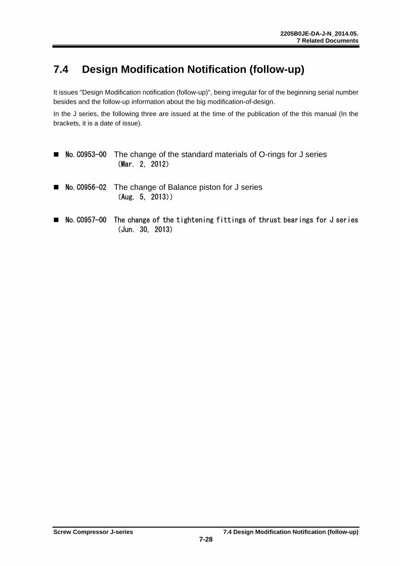
2205B0JE-DA-J-N_2014.05. 7 Related Documents
Screw Compressor J-series 7.4 Design Modification Notification (follow-up) 7-28
7.4 Design Modification Notification (follow-up) It issues "Design Modification notification (follow-up)", being irregular for of the beginning serial number besides and the follow-up information about the big modification-of-design. In the J series, the following three are issued at the time of the publication of the this manual (In the brackets, it is a date of issue).
No.C0953-00 The change of the standard materials of O-rings for J series (Mar. 2, 2012)
No.C0956-02 The change of Balance piston for J series (Aug. 5, 2013))
No.C0957-00 The change of the tightening fittings of thrust bearings for J series
(Jun. 30, 2013)
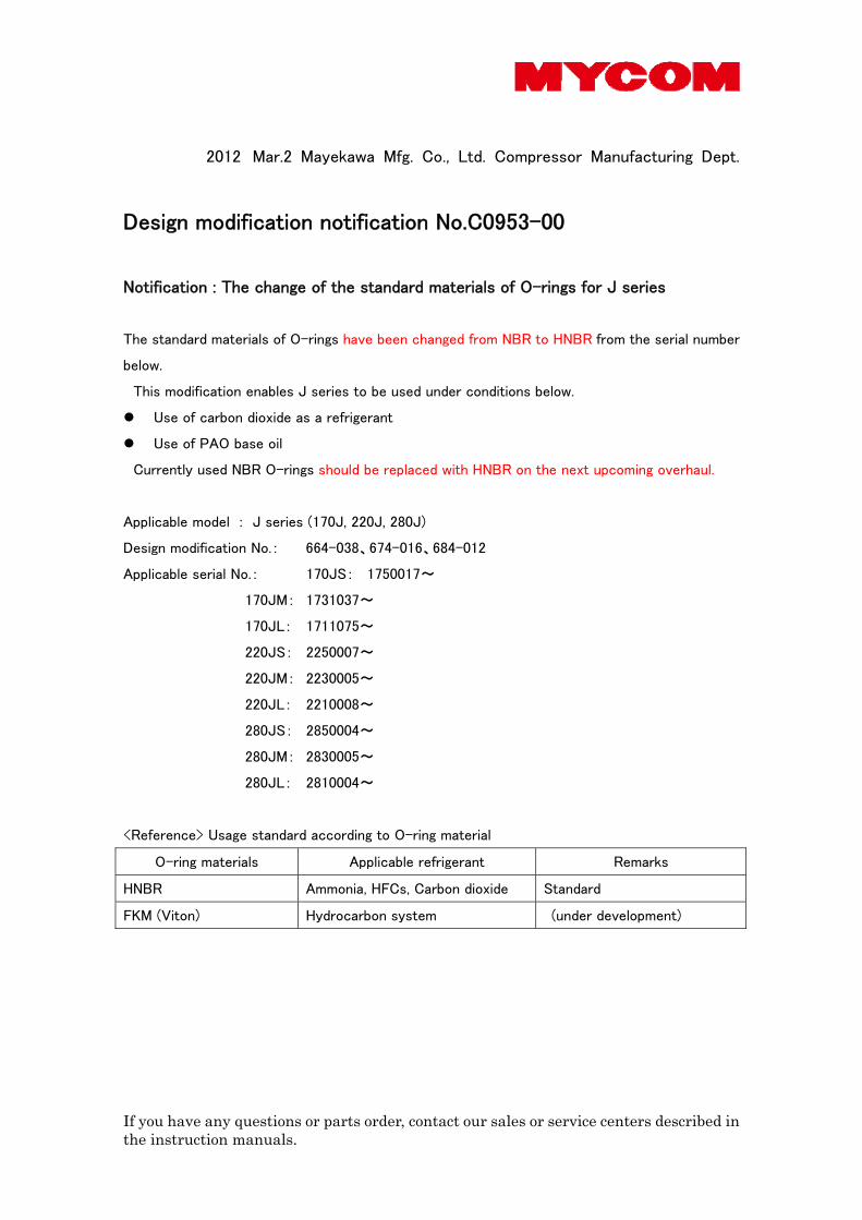
If you have any questions or parts order, contact our sales or service centers described in the instruction manuals.
2012 Mar.2 Mayekawa Mfg. Co., Ltd. Compressor Manufacturing Dept.
Design modification notification No.C0953-00
Notification : The change of the standard materials of O-rings for J series
The standard materials of O-rings have been changed from NBR to HNBR from the serial number
below.
This modification enables J series to be used under conditions below.
Use of carbon dioxide as a refrigerant
Use of PAO base oil
Currently used NBR O-rings should be replaced with HNBR on the next upcoming overhaul.
Applicable model : J series (170J, 220J, 280J)
Design modification No.: 664-038、674-016、684-012
Applicable serial No.: 170JS: 1750017~
170JM: 1731037~
170JL: 1711075~
220JS: 2250007~
220JM: 2230005~
220JL: 2210008~
280JS: 2850004~
280JM: 2830005~
280JL: 2810004~
<Reference> Usage standard according to O-ring material
O-ring materials Applicable refrigerant Remarks
HNBR Ammonia, HFCs, Carbon dioxide Standard
FKM (Viton) Hydrocarbon system (under development)
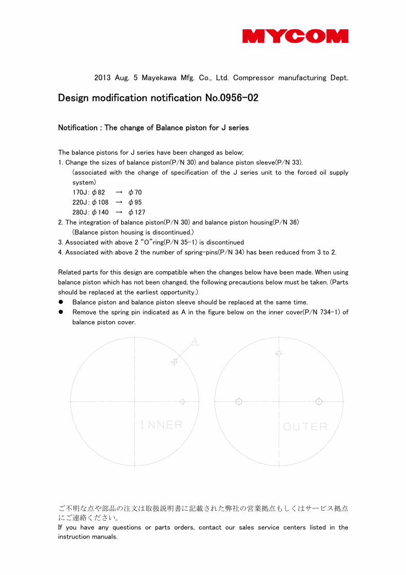
ご不明な点や部品の注文は取扱説明書に記載された弊社の営業拠点もしくはサービス拠点
にご連絡ください。 If you have any questions or parts orders, contact our sales service centers listed in the
instruction manuals.
2013 Aug. 5 Mayekawa Mfg. Co., Ltd. Compressor manufacturing Dept.
Design modification notification No.0956-02
Notification : The change of Balance piston for J series
The balance pistons for J series have been changed as below;
1. Change the sizes of balance piston(P/N 30) and balance piston sleeve(P/N 33).
(associated with the change of specification of the J series unit to the forced oil supply
system)
170J:φ82 → φ70
220J:φ108 → φ95
280J:φ140 → φ127
2. The integration of balance piston(P/N 30) and balance piston housing(P/N 36)
(Balance piston housing is discontinued.)
3. Associated with above 2 “O”ring(P/N 35-1) is discontinued
4. Associated with above 2 the number of spring-pins(P/N 34) has been reduced from 3 to 2.
Related parts for this design are compatible when the changes below have been made. When using
balance piston which has not been changed, the following precautions below must be taken. (Parts
should be replaced at the earliest opportunity.)
Balance piston and balance piston sleeve should be replaced at the same time.
Remove the spring pin indicated as A in the figure below on the inner cover(P/N 734-1) of
balance piston cover.

ご不明な点や部品の注文は取扱説明書に記載された弊社の営業拠点もしくはサービス拠点
にご連絡ください。 If you have any questions or parts orders, contact our sales service centers listed in the
instruction manuals.
Applicable model: J series (170J, 220J, 280J)
Design modification No.: 664-056、664-057、674-033、674-034、684-037、684-038
Applicable serial No.:After the number indicated below modified parts are mounted.
170JS: 1751017
170JM: 1731037
170JL: 1711105
220JS: 2250021*2
220JM: 2230034
220JL: 2210040
280JS: 2850030*2
280JM: 2830022*2
280JL: 2810010*2
However, the serial numbers indicated below have mounted modified balance pistons in advance.
170JS 1751015*1
170JL 1711082、1711087、1711095、1711096、1711097、1711098、1711099
220JM 2230014、2230015、2230016、2230017、2230033*1
280JS 2850023
※ Do not use the compressors with unmodified balance pistons with forced oil supply system.
units.
Before change After change
*1 Addition (1751015, 2230033) 2013 May. 13
*2 Addition (2250021, 2810010, 2810011, 2810012, 2810013, 2810014, 2810015, 2810016,
2830022, 2830023, 2830024, 2850030, 2850031, 2850032) 2013 Aug. 5
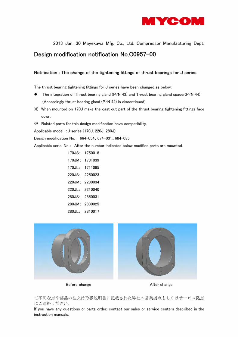
ご不明な点や部品の注文は取扱説明書に記載された弊社の営業拠点もしくはサービス拠点
にご連絡ください。 If you have any questions or parts order, contact our sales or service centers described in the
instruction manuals.
2013 Jan. 30 Mayekawa Mfg. Co., Ltd. Compressor Manufacturing Dept.
Design modification notification No.C0957-00
Notification : The change of the tightening fittings of thrust bearings for J series
The thrust bearing tightening fittings for J series have been changed as below;
The integration of Thrust bearing gland (P/N 43) and Thrust bearing gland spacer(P/N 44)
(Accordingly thrust bearing gland (P/N 44) is discontinued)
※ When mounted on 170J make the cast out part of the thrust bearing tightening fittings face
down.
※ Related parts for this design modification have compatibility.
Applicable model : J series (170J, 220J, 280J)
Design modification No.: 664-054、674-031、684-035
Applicable serial No.: After the number indicated below modified parts are mounted.
170JS: 1750018
170JM: 1731039
170JL: 1711095
220JS: 2250023
220JM: 2230034
220JL: 2210040
280JS: 2850031
280JM: 2830025
280JL: 2810017
Before change After change
2205B0JE-DA-J-N_2014.05.
Screw Compressor J-series Appendix 1.1 Precautions for Design of the Compressor Package Appendix1-1
Appendix 1 Tips for Design, Manufacturing, and Installation of the Compressor Package
The J-series screw compressor is delivered as a package in standard. The appendix describes points to be considered when designing or manufacturing the package or installing the compressor package.
Appendix 1.1 Precautions for Design of the Compressor Package
Working Limits of the Compressor Understand and adhere to the instructions in “2.3 Operation Limits” in this manual chapter 2, so that the package is designed within the specified operating limits.
The following points are important for the compressor to operate within the operating limits.
Regulate the minimum differential pressure for lubrication within the specifications. For life time of thrust bearing, sufficient lubrication.
Ensure appropriate flow rate of the lubricant (appropriate pipe diameter) for lubricating and cooling bearings and seals and discharge gas.
Compressor Protection Function When placing the compressor into a new or an existing system, always use the specified controller to control and protect the compressor.
Set the following control values for compressor protection in consideration of the compressor operating limits.
(1) Protection from abnormal high pressure (2) Protection from abnormal low suction pressure
(3) Protection from low supply oil pressure (4) Protection from high supply oil temperature
(5) Protection from high discharge temperature
(6) Protection from overcurrent
In addition, install safety valves to pressure vessels such as oil separator, condenser, and evaporator.
Operating Control The specified controller (CP4) for the compressor incorporates the following operational controls that allow the package to operate smoothly and safely.
1) Start-up preparation control
The following controls are performed before the compressor is started up.
• The capacity control slide valve of the compressor is checked to see if it is at the minimum load position.
• The compressor is lubricated before start-up.
2) Operating control
In normal operation state, the following operational controls are performed.
• The compressor capacity is controlled according to the load so that the predetermined temperature or pressure is constant.
• The compressor stops automatically when the operating conditions reach the set points.
• Vi is controlled according to the compressor operating conditions.
2205B0JE-DA-J-N_2014.05.
Screw Compressor J-series Appendix 1.1 Precautions for Design of the Compressor Package Appendix1-2
3) Control for compressor stop
The following controls are performed before the compressor is stopped.
• The capacity control slide valve of the compressor is set to the minimum position before it is stopped. (Alternatively, the compressor is stopped with the capacity control slide valve is in the low load position and the capacity control slide valve is set to the 0% position after it is stopped.)
Motor The 170J/220J-series is intended for a flange motor in standard.
It is applied for the following standards and frames.
170J 220J
• NEMA 44*D, 55*D
• IEC FF-500, FF-600
• NEMA 44*D, 50*D
• IEC FF-600, FF-740
Oil Separator The oil separator is required to separate and hold compressor lubricant oil, therefore take the following points into consideration during design.
1) Oil separation performance
Design the oil separator so that the quantity of oil carried away from the oil separator is below
10 ppm. Consider the gravitational sedimentation method and the types of filter to use.
2) Amount of lubricant held
The amount of lubricant held in the oil separator must at least be more than 1.5 times the supply lubricant flow rate per minute.
3) Attachment of oil level gauge
To manage the lubricant level, an oil level gauges that shows both the upper and lower level limit must be provided.
4) Installation of oil heater
An oil heater must be installed at the bottom of the oil separator with appropriate temperature settings to prevent excessive viscosity increase of lubricant, condensation of refrigerant, and refrigerant dissolving in lubricant at start up.
If the package is for use in cold regions or the lubricant dissolves excessively in the refrigerant, the oil separator must be thermally insulated.
5) Sufficient stiffness
If a horizontal type of oil separator with the compressor and motor mounted on top is adopted, the oil separator must be sufficiently rigidly designed.
The oil separator must have sufficient rigid structure so that no misalignment
trouble occurs to the compressor and motor during operation due to the oil separator heat stress or deformation due to pressure.
2205B0JE-DA-J-N_2014.05.
Screw Compressor J-series Appendix 1.1 Precautions for Design of the Compressor Package Appendix1-3
Oil Cooler The oil cooler must have adequate capacity to sufficiently dissipate heat from the oil.
The oil cooler must be designed with minimum pressure loss.
Some of oil cooler types are: 1. water cooling, 2.Thermosyphon, 3. direct expansion.
Large pressure loss may lead to insufficient supply of lubricant. In other cases,
lubrication problems may occur inside the compressor due to the vaporized refrigerant gas from the lubricant (refrigerant gas that may have dissolved (or mixed) in the lubricant.)
Instead of using a shell and tube or plate and frame oil cooler, oil may be cooled by supplying liquid refrigerant to the compressor (liquid injection system). In this case, liquid injection flow rate must be controlled so that the discharge superheat is maintained at an appropriate temperature.
Notice that excessive liquid injection may cause the lubricant in the oil separator
to foam, resulting in excessive oil carried away from oil separator and insufficient lubrication to the compressor components. In other cases, refrigerant solution in lubricant may reduce the lubricant viscosity.
Oil Pipe Installation The J-series requires the following three oil lines: lubrication, oil injection, and unloader/variable Vi system oil lines.
1) Lubrication oil line
For the lubrication system, an inlet port of ANSI #300 1” (common in J-series) is provided on the bearing head and another inlet port of Rc1/2 (170J), Rc3/4 (220J), or ANSI #300 3/4” (280J) is also provided on the suction cover.
Because the J-series uses hydrodynamic bearings, it requires pre-lubrication before start-up. Therefore, a pre-lubrication pump must be installed. Note, the supply lubricant line located upstream of the pre-lubrication pump must be installed with a check valve.
2) Oil injection oil line
For oil injection, an inlet port of Rc1/2 (170J), Rc3/4 (220J), or ANSI #300 1 1/4” (280J) is provided on the male rotor side of the main rotor casing and should be used in normal cases. (In some cases when the discharge temperature is higher than limit temperature, the female rotor side injection port may be used at the same time.)
The oil injection line must be installed with a check valve to prevent reversed flow.
3) Oil line for the Unloader, Vi cylinder
For 170J/220J-series, an Rc1/2 port (interchangeable with NPT1/2) for oil supply to the unloader and Vi cylinder is provided on the male rotor side of the unloader cylinder. The oil outlet port for the unloader and Vi cylinder is an Rc1/2 port on the female rotor side.
For 280J-series, connect between the ports (4 places) with corresponding ports of the solenoid valve.
Make sure that the oil line is connected to the suction line located upstream of the suction flange which is integrated with suction check valve.

2205B0JE-DA-J-N_2014.05.
Screw Compressor J-series Appendix 1.1 Precautions for Design of the Compressor Package Appendix1-4
Oil Pump When using booster to make minimum differential oil pressure (the differential pressure between oil supply pressure and suction pressure) should be more than 0.5MPa, an oil pump which can refill all oil volume should be provided.
Under high pressure conditions; discharge pressure is more than 2.2Mpa or suction pressure is more than 0.8MPa, to make thrust bearing service life longer, an oil pump which can refill all oil volume should be provided.
The oil pump is also required for lubrication before start-up and to move capacity control slide valve and the variable Vi slide valve when the compressor is stopped.
The oil pump must be installed after the oil filter.
Oil Filter To eliminate contaminants in the lubricant, an oil filter (main filter) must be installed in the oil line.
According to the requirements of the use of the package unit or the standard to apply, install an oil filter of appropriate filtration precision in the lubrication system of the compressor.
In the case of general applications such as closed-cycle refrigeration systems, we recommend to use an oil filter with beta ratio in the range of β20 ≥ 150 that conforms to requirements of NAS 1638 class 8 or ISO 4406 17/15/13.
When the package unit requires API 619 4th/5th edition conformity, use an oil filter with beta ratio in the range of β10≥200.
Any contaminants in the lubricant may cause damage to important components
such as bearings and shaft seal.
Economizer Piping To install economizer piping, follow the instructions below.
1) When an economizer is used, the E plug (728) must be removed. Refer to Sectional View 3/3.
2) For 170J-series, remove the blind flange for the economizer (ANSI #300 1") to access the E plug. The E plug head is exposed and a tool (socket, size 18) can be fitted to the head of the E plug. Use a wrench to remove the E plug.
For 220J/280J-series, first remove the E plug flange (728-3). Then remove the E plug gland (728-2) and the E plug in this order by using the eye bolt (M8).
3) For 170J-series, insert a R3/4 hexagon socket headless tapered pipe plug after removing the E plug. The plug must be a metric taper screw plug. (Do not use a NPT plug.) After attaching the R3/4 plug, apply anticorrosive paint to the plug head and the counter bore. Applying grease additionally is more effective for rust proofing.
For 220J/280J-series, reattach the E plug flange and the E plug gland after removing the E plug.
4) To connect the pipe for the economizer port, use ANSI #300 flanges. The flange size is 1B for 170J, 1 1/2B for 220J, and 2 1/2B for 280J.
5) While installing the pipes, take sufficient care not to allow any contamination such as spatters to remain in the piping and enter the compressor.

2205B0JE-DA-J-N_2014.05.
Screw Compressor J-series Appendix 1.1 Precautions for Design of the Compressor Package Appendix1-5
Liquid Injection Piping To install liquid injection piping, follow the instructions below.
1) To connect the pipe for the liquid injection port, use ANSI #300 flanges. The flange size is 3/4B for 170J/220J and 1B for 280J.
2) While installing the pipes, take sufficient care not to allow any contamination such as spatters to remain in the piping and enter the compressor.
Suction Piping For 170J/220J-series, before connecting the suction pipes, apply grease or liquid gasket (such as HERME SEAL) to the counter bores, bolt heads, holes of the hexagon socket head cap screws (493) fastening the suction adapter (492) to prevent rust and freeze up.
Make sure that the suction check valve located below the compressor suction flange is not subjected to excessive force or damaged during installation of the suction pipe.
If no rustproof and freezing-proof coating is applied to the hexagon socket head
cap screws fastening the suction adapter, the suction flange and bolts may be damaged.
Miscellaneous
1) Suction/discharge check valve
The 170J-220J-series integrates a suction check valve.
For the discharge side, a separate discharge check valve must be installed at the outlet of the oil separator.
When two or more compressors are installed with a single oil separator, check
valves must be installed in each discharge pipes between the compressors and the oil separator.
2) Suction strainer
To prevent foreign substances from entering the compressor, a suction gas strainer must be installed in the suction line of the compressor.
Equal to or more than 100 meshes (equal to or more than 200 meshes when using a dry process evaporator ) are recommended for the suction gas strainer.
2205B0JE-DA-J-N_2014.05.
Screw Compressor J-series Appendix 1.2 Tips for Compressor Package Manufacturing Appendix1-6
Appendix 1.2 Tips for Compressor Package Manufacturing
Piping arrangements, Vessel Any foreign substances in the lubricant will affect lubrication of the compressor bearings and mechanical seal, resulting in compressor failures. To prevent such problems, components such as oil separators, oil coolers, oil filters and suction gas strainers must be cleaned to remove all foreign substances. The main pipes must be cleaned by shot blast or pickling before installation. In particular, the lubricant piping from the oil filter to the compressor port and the suction piping after the suction gas strainer to the compressor suction must be thoroughly cleaned.
Appendix 1.3 Tips for Compressor Package Installation
Installation of Compressor and Motor to the package For coupling the 170J/220J-series compressor with the flange motor and fastening them to the compressor base, follow the instructions below.
1. Remove any adhesive matters such as paint from the motor spacer side flange face of the compressor bearing cover using a scraper and brass wire brush, and clean the face with a solvent (such as kerosine). Check the flange face for damage. Rectify any scratches and damage.
2. Clean the compressor side flange face of the motor spacer using a solvent.
3. Place the compressor on a working table. Make sure to prepare sleepers with a height of 120 mm or more to use as the compressor base because the motor side flange diameter is bigger than the compressor side flange diameter.
4. Attach two safety bolts (M16×60) to the upper two bolt holes on the flange face of the bearing cover motor spacer side.
5. Lift the motor spacer with lifting equipment such as a crane and move it horizontally to align with the compressor side flange face of the compressor bearing cover flange face using the safety bolts on the bearing cover as the guides.
6. From the motor spacer side, insert two hexagon socket head cap screws (M16×20) at diagonal positions and lightly tighten them by wrench evenly so that no gap is present between the flange faces.
7. Apply lubricant (for example, molybdenum disulfide) to the parallel pin (13 dia. × 60) and insert it by knocking with a copper hammer from the motor spacer side.
8. Remove the safety bolts and insert the remaining bolts from the motor spacer side, then tighten all bolts to the specified torque in a star pattern.
9. Lift the compressor with motor spacer using lifting equipment such as a crane hooking on the three eyebolts on the compressor, place it on the compressor base of the package, and fix the motor spacer and compressor feet to the compressor base with bolts.
10. Lift the motor using lifting equipment such as a crane, put the spigot of the motor in the recess of motor spacer, and fit the motor flange face and the motor spacer flange face.
11. Insert two bolts at the diagonal positions from the motor side, and tighten them evenly so that no gap is present between the flange faces.
12. Insert the remaining bolts and tighten all bolts to the specified torque.
13. Remove the crane and finally tighten the two bolts on the counter-load side motor feet.
14. If there is any gap between the motor feet and the motor base, adjust the height by inserting shims before tightening the bolts.
2205B0JE-DA-J-N_2014.05.
Screw Compressor J-series Appendix 1.3 Tips for Compressor Package Installation Appendix1-7
With these steps, the coupling of flange motor and compressor and fastening them to the compressor base is finished.
If there is any gap left between the base and the motor feet, the compressor and
motor spacer can be strained, which may lead not only to abnormal noises and vibrations but also damage to the bearing or leak from the mechanical seal.
When the compressor is the 280J-series or when the compressor and the motor are coupled without a motor spacer, the four feet of the compressor and motor must be firmly fastened to the compressor and motor bases.
In this case, the couplings of the motor and the compressor must be aligned. (For detailed procedure, refer to the package instruction manual.)
Suction Gas Line Piping When installing the suction piping to the compressor package, provide pipe supports at appropriate positions so that the compressor suction flange is not subject to excessive loads.
Any excessive loads to the compressor from the piping may cause compressor
casing deformation, resulting in mechanical problems.
Foundation for Compressor Package The compressor package must be mounted on a solid floor or foundation. The package must be firmly fixed to the foundation with anchor bolts after leveling and aligning.
If the package is mounted on a floor or foundation without sufficient
reinforcement, abnormal vibrations may occur from the compressor and/or the package.
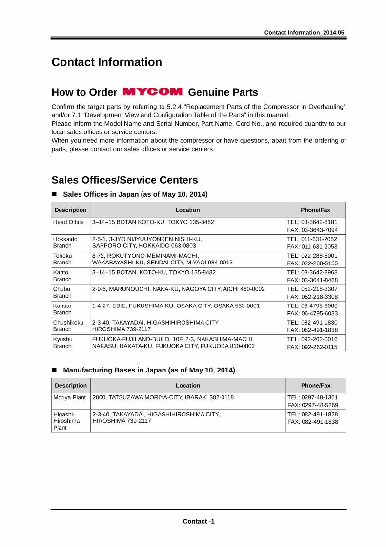
Contact Information_2014.05.
Contact -1
Contact Information
How to Order Genuine Parts Confirm the target parts by referring to 5.2.4 "Replacement Parts of the Compressor in Overhauling" and/or 7.1 "Development View and Configuration Table of the Parts" in this manual. Please inform the Model Name and Serial Number, Part Name, Cord No., and required quantity to our local sales offices or service centers. When you need more information about the compressor or have questions, apart from the ordering of parts, please contact our sales offices or service centers.
Sales Offices/Service Centers Sales Offices in Japan (as of May 10, 2014)
Description Location Phone/Fax
Head Office 3–14–15 BOTAN KOTO-KU, TOKYO 135-8482 TEL: 03-3642-8181 FAX: 03-3643-7094
Hokkaido Branch
2-5-1, 3-JYO NIJYUUYONKEN NISHI-KU, SAPPORO-CITY, HOKKAIDO 063-0803
TEL: 011-631-2052 FAX: 011-631-2053
Tohoku Branch
8-72, ROKUTYONO-MEMINAMI-MACHI, WAKABAYASHI-KU, SENDAI-CITY, MIYAGI 984-0013
TEL: 022-288-5001 FAX: 022-288-5155
Kanto Branch
3–14–15 BOTAN, KOTO-KU, TOKYO 135-8482 TEL: 03-3642-8968 FAX: 03-3641-8468
Chubu Branch
2-9-6, MARUNOUCHI, NAKA-KU, NAGOYA CITY, AICHI 460-0002 TEL: 052-218-3307 FAX: 052-218-3308
Kansai Branch
1-4-27, EBIE, FUKUSHIMA-KU, OSAKA CITY, OSAKA 553-0001 TEL: 06-4795-6000 FAX: 06-4795-6033
Chushikoku Branch
2-3-40, TAKAYADAI, HIGASHIHIROSHIMA CITY, HIROSHIMA 739-2117
TEL: 082-491-1830 FAX: 082-491-1838
Kyushu Branch
FUKUOKA-FUJILAND-BUILD. 10F, 2-3, NAKASHIMA-MACHI, NAKASU, HAKATA-KU, FUKUOKA CITY, FUKUOKA 810-0802
TEL: 092-262-0016 FAX: 092-262-0115
Manufacturing Bases in Japan (as of May 10, 2014)
Description Location Phone/Fax
Moriya Plant 2000, TATSUZAWA MORIYA-CITY, IBARAKI 302-0118 TEL: 0297-48-1361 FAX: 0297-48-5269
Higashi- Hiroshima Plant
2-3-40, TAKAYADAI, HIGASHIHIROSHIMA CITY, HIROSHIMA 739-2117
TEL: 082-491-1828 FAX: 082-491-1838
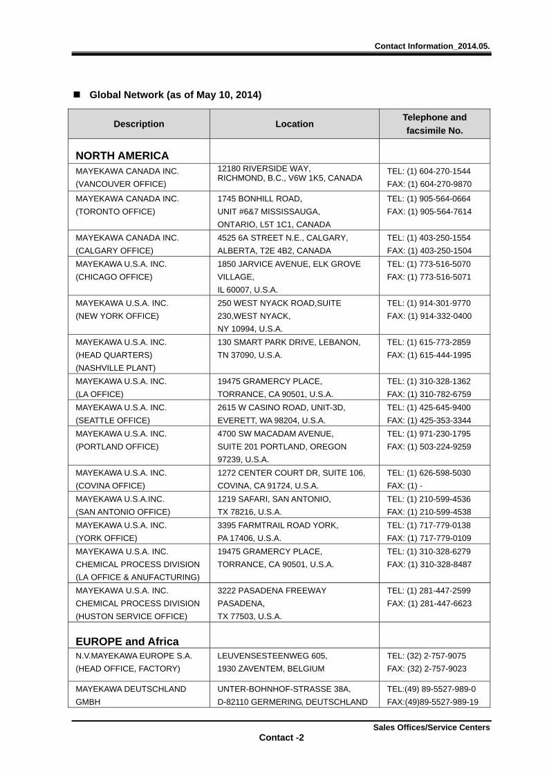
Contact Information_2014.05.
Sales Offices/Service Centers Contact -2
Global Network (as of May 10, 2014)
Description Location Telephone and
facsimile No.
NORTH AMERICA
MAYEKAWA CANADA INC.
(VANCOUVER OFFICE)
12180 RIVERSIDE WAY, RICHMOND, B.C., V6W 1K5, CANADA
TEL: (1) 604-270-1544
FAX: (1) 604-270-9870
MAYEKAWA CANADA INC.
(TORONTO OFFICE)
1745 BONHILL ROAD,
UNIT #6&7 MISSISSAUGA,
ONTARIO, L5T 1C1, CANADA
TEL: (1) 905-564-0664
FAX: (1) 905-564-7614
MAYEKAWA CANADA INC.
(CALGARY OFFICE)
4525 6A STREET N.E., CALGARY,
ALBERTA, T2E 4B2, CANADA
TEL: (1) 403-250-1554
FAX: (1) 403-250-1504
MAYEKAWA U.S.A. INC.
(CHICAGO OFFICE)
1850 JARVICE AVENUE, ELK GROVE
VILLAGE,
IL 60007, U.S.A.
TEL: (1) 773-516-5070
FAX: (1) 773-516-5071
MAYEKAWA U.S.A. INC.
(NEW YORK OFFICE)
250 WEST NYACK ROAD,SUITE
230,WEST NYACK,
NY 10994, U.S.A.
TEL: (1) 914-301-9770
FAX: (1) 914-332-0400
MAYEKAWA U.S.A. INC.
(HEAD QUARTERS)
(NASHVILLE PLANT)
130 SMART PARK DRIVE, LEBANON,
TN 37090, U.S.A.
TEL: (1) 615-773-2859
FAX: (1) 615-444-1995
MAYEKAWA U.S.A. INC.
(LA OFFICE)
19475 GRAMERCY PLACE,
TORRANCE, CA 90501, U.S.A.
TEL: (1) 310-328-1362
FAX: (1) 310-782-6759
MAYEKAWA U.S.A. INC.
(SEATTLE OFFICE)
2615 W CASINO ROAD, UNIT-3D,
EVERETT, WA 98204, U.S.A.
TEL: (1) 425-645-9400
FAX: (1) 425-353-3344
MAYEKAWA U.S.A. INC.
(PORTLAND OFFICE)
4700 SW MACADAM AVENUE,
SUITE 201 PORTLAND, OREGON
97239, U.S.A.
TEL: (1) 971-230-1795
FAX: (1) 503-224-9259
MAYEKAWA U.S.A. INC.
(COVINA OFFICE)
1272 CENTER COURT DR, SUITE 106,
COVINA, CA 91724, U.S.A.
TEL: (1) 626-598-5030
FAX: (1) -
MAYEKAWA U.S.A.INC.
(SAN ANTONIO OFFICE)
1219 SAFARI, SAN ANTONIO,
TX 78216, U.S.A.
TEL: (1) 210-599-4536
FAX: (1) 210-599-4538
MAYEKAWA U.S.A. INC.
(YORK OFFICE)
3395 FARMTRAIL ROAD YORK,
PA 17406, U.S.A.
TEL: (1) 717-779-0138
FAX: (1) 717-779-0109
MAYEKAWA U.S.A. INC.
CHEMICAL PROCESS DIVISION
(LA OFFICE & ANUFACTURING)
19475 GRAMERCY PLACE,
TORRANCE, CA 90501, U.S.A.
TEL: (1) 310-328-6279
FAX: (1) 310-328-8487
MAYEKAWA U.S.A. INC.
CHEMICAL PROCESS DIVISION
(HUSTON SERVICE OFFICE)
3222 PASADENA FREEWAY
PASADENA,
TX 77503, U.S.A.
TEL: (1) 281-447-2599
FAX: (1) 281-447-6623
EUROPE and Africa
N.V.MAYEKAWA EUROPE S.A.
(HEAD OFFICE, FACTORY)
LEUVENSESTEENWEG 605,
1930 ZAVENTEM, BELGIUM
TEL: (32) 2-757-9075
FAX: (32) 2-757-9023
MAYEKAWA DEUTSCHLAND
GMBH
UNTER-BOHNHOF-STRASSE 38A,
D-82110 GERMERING, DEUTSCHLAND
TEL:(49) 89-5527-989-0
FAX:(49)89-5527-989-19

Contact Information_2014.05.
Sales Offices/Service Centers Contact -3
Description Location Telephone and
facsimile No.
MAYEKAWA DEUTSCHLAND
GMBH (HUMBURG OFFICE)
WEIDESTRASSE 122A, 22083
HAMBURG, DEUTSCHLAND
TEL:(49)40-2788-9149-0
FAX:(49)40-2788-9149-9 N.V.MAYEKAWA EUROPE S.A.(UK)
16 OAKHURST GARDENS,
BEXLEYHEATH,
KENT DA7 5JP, UNITED KINGDOM
TEL: (44) 1322-433558
FAX: (44) 1322-433164
MAYEKAWA. S.L. CALLE MONTEVIDEO 5, NAVE 13 POL.
INDUSTRIAL CAMPORROSO 28806
ALCALA DE HENARES, MADRID, SPAIN
TEL: (34) 91-830-0392
FAX: (34) 91-830-0397
MAYEKAWA FRANCAISE SARL 9, RUE MICHAEL FARADAY, 78180
MONTIGNY-LE-BRETONNEUX,
FARNCE
TEL: (33) 1-30-58-26-00
FAX: (33) 1-30-58-19-37
MAYEKAWA MFG. CO., LTD.
MOSCOW LIAISON OFFICE
KOROVY VAL ST., 7, OFFICE 228,
119049, MOSCOW,RUSSIA
TEL: (7) 499-230-01-76
FAX: (7) 499-230-21-12
MAYEKAWA INTERTEC AG ROSENBERGSTRASSE 31, CH-6300
ZUG,
SWITZERLAND
TEL: (41) 41-726-8626
FAX: (41) 41-726-8620
MAYEKAWA INTERTEC AG
- EGYPT
P.O.BOX 341
NEW CAIRO - 5th SETTLEMENT,
NORTH 90th St. THE 47th BUILDING -
4th FLOOR, OFFICE 419, EGYPT
TEL: (20) 22-503-2925
FAX: (20) 22-503-2801
MAYEKAWA MIDDLE EAST
FZCO
P.O.BOX 61349, PBU: RA08-UC05,
JEBEL ALI FREE ZONE, DUBAI, U.A.E.
TEL: (971) 4-888-6363
FAX: (971) 4-888-6373
MAYEKAWA TURKEY SOGUTMA
SANAYI VE TICARET LIMITED
SIRKETI
ISTANBUL DUNYA TICARET MERKEZI
A-2 BLOK KAT 10 No:325 YESILKOY
34149,
ISTANBUL, TURKEY
TEL: (90) 212-4653631
FAX: (90) 212-4653635
N.V. MAYEKAWA EUROPE S.A.
(BULGARIA)
24,KAMEN ANDREEV STR. 1303,
SOFIA,
BULGARIA
TEL: (359) 2-8910130
FAX: (359) 2-8910131
MAYEKAWA ITALIA S.R.L.
(MILANO OFFICE)
VIA RICCARDO LOMBARDI 19/12,
20153 MILANO, ITALY
TEL: (39) 02-4892-9159
FAX: (39) 02-453-1728
MAYEKAWA ITALIA S.R.L.
(BOLOGNA OFFICE)
VIA PRADAZZO 7,40012 CALDERARA
DI RENO,,
BOLOGNA, ITALY
TEL: (39) 051-726-364
FAX: (39) 051-726-804
MAYEKAWA SOUTH AFRICA
(PTY) LTD.
(CAPE TOWN OFFICE)
WEST END, UNIT 3 PRIME PARK,
PRINTERS WAY, MONTAGUE
GARDENS 7441, REPUBLIC OF SOUTH
AFRICA
TEL: (27) 21-551-1434
FAX: (27) 86-546-3618
ASIA PACIFIC
MAYEKAWA AUSTRALIA
PTY.LTD.
UNIT 2, 44 MCCAULEY STREET
MATRAVILLE NSW 2036, AUSTRALIA
TEL: (61) 2-9695-7000
FAX: (61) 2-9695-7001
MAYEKAWA AUSTRALIA PTY.
LTD.(NEW ZEALAND OFFICE)
UNIT 2, 30 TUI STREET, OTAHUHU,
AUCKLAND 2024, NEW ZEALAND
TEL: (64) 9-276-2305
FAX: (64) 9-276-2306

Contact Information_2014.05.
Sales Offices/Service Centers Contact -4
Description Location Telephone and
facsimile No.
MAYEKAWA INDIA PVT.LTD.
(GURGAON OFFICE)
545, 1st FLOOR, SECTOR-20,VILLAGE
DUNDAHERA
GURAGAON-122016, HARYANA, INDIA
TEL: (91) 12-4651-0181
FAX: (91) 12-4651-0188
MAYEKAWA INDIA PVT.LTD.
(CHENNAI FACTORY)
RS No.225/226/238,NAYAPAKKAM
VILLAGE,
PUDDUVALLUR PANCHAYAT,
VALARPURAM POST THIRUVALLUR
DISTRICT,
TAMIL NADU 602105, INDIA
TEL: (91) 92-8258-2508
FAX: -
MAYEKAWA INDIA PVT. LTD.
(KOLKATA OFFICE)
OMER MANSION, ROOM No. 2c, 3RD
FLOOR,
29 A WESTON STREET, KOLKATA,
WEST BENGAL 700012, INDIA
TEL: (91) 33-40038043
FAX: (91) 33-40038044
MAYEKAWA INDIA PVT. LTD.
(JALANDHAR OFFICE)
SHOP NO. 3, OPP. TV TOWER,
NIKODAR ROAD, JALANDHAR, PUNJAB
144201, INDIA
TEL: (91) 9711303865
FAX: —
MAYEKAWA INDIA PVT. LTD.
(AGRA OFFICE)
CS-9 SECOND FLOOR, RASHMI
PALACE, SULTAN GANJ KI PULIA,
KAMLA NAGAR, AGRA, U.P. 282005,
INDIA
TEL: (91) 89-5450-2937
FAX: (91) 97-1130-3865
P.T.MAYEKAWA INDONESIA GRAHA PRATAMA BUILDING, 9TH
FLOOR JL. M.T. HARYONO KAV.15
JAKARTA 12810, INDONESIA
TEL: (62) 21-8370-9484
FAX: (62) 21-8370-9483
P.T.MAYEKAWA INDONESIA
(MEDAN OFFICE)
JL. SUTRISNO No.274 MEDAN-20215,
INDONESIA
TEL: (62) 61-7323627
FAX: (62) 61-7358848
P.T.MAYEKAWA INDONESIA
(SURABAYA OFFICE)
BUMI MANDIARI BUILDING, 7TH
FLOOR SUITE 702B, JL. JEND. BASUKI
RACHMAT No. 129-137,
SURABAYA-INDONESIA
TEL: (62) 31-531-6613
FAX: (62) 31-532-4341
MAYEKAWA (M) SDN. BHD. No.3, JALAN PJU 3/50, SUNWAY
DAMANSARA TECHNOLOGY PARK,
47810 PETALING JAYA, SELANGOR,
MALAYSIA
TEL: (60) 3-78051406
FAX: (60) 3-78051409
MAYEKAWA PHILIPPINES
CORP.
4/F UNIT A AND B SUNTREE TOWER,
13 MERALCO AVENUE, SAN ANTONIO,
ORTIGAS CENTER, PASIG CITY 1605,
PHILIPPINES
TEL: (63) 2-706-0473
FAX: (63) 2-706-0475
MAYEKAWA PHILIPPINES
CORP.
(GENARAL SANTOS OFFICE)
ROOM 4, LEAH DAPROZA BUILDING
FISCAL DAPROZA AVENUE
GENERAL SANTOS CITY 9500,
PHILIPPINES
TEL: (63) 83-552-3282
FAX: (63) 83-301-2698
MAYEKAWA SINGAPORE
PTE.LTD.
6 TAGORE LANE SINGAPORE 787470
TEL: (65) 6451-1565
FAX: (65) 6451-4932
MAYEKAWA (TAIWAN) CO., LTD. No.2-1,XINZHAN RD.,QIANZHEN DIST.,
KAOHSIUNG CITY,80672
TAIWAN , REP.OF CHINA
TEL: (886) 7-821-0886
FAX: (886) 7-821-4688
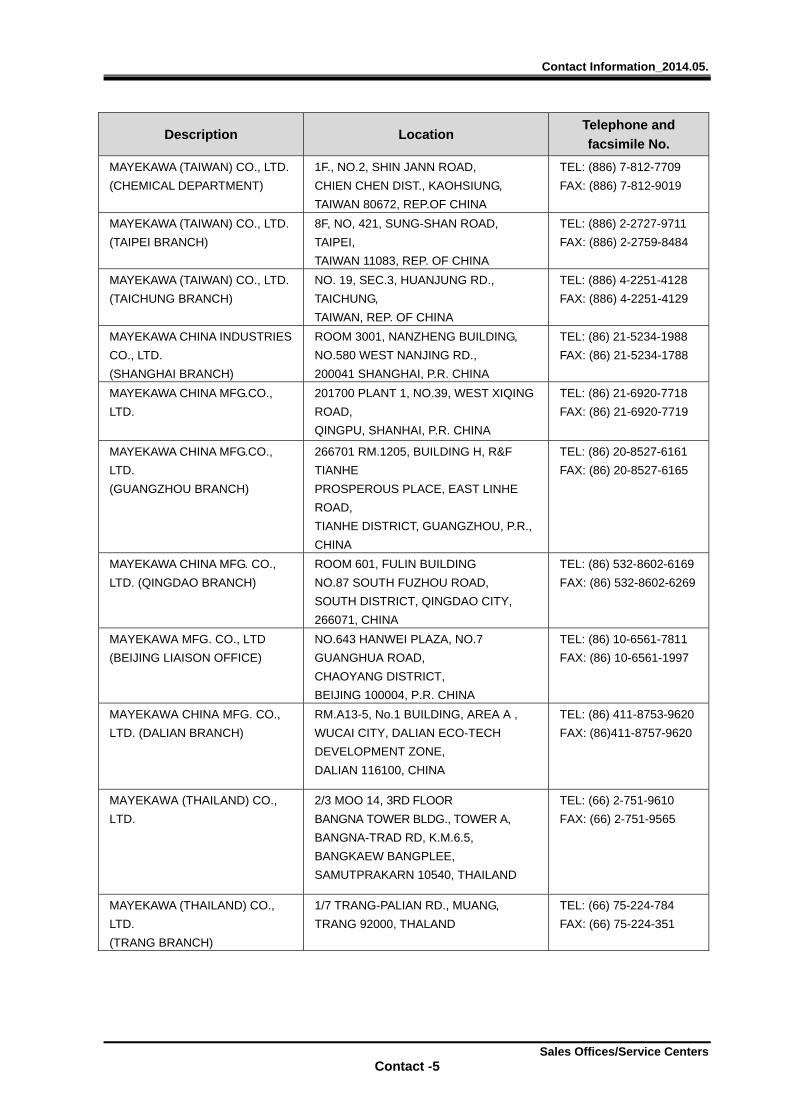
Contact Information_2014.05.
Sales Offices/Service Centers Contact -5
Description Location Telephone and
facsimile No.
MAYEKAWA (TAIWAN) CO., LTD.
(CHEMICAL DEPARTMENT)
1F., NO.2, SHIN JANN ROAD,
CHIEN CHEN DIST., KAOHSIUNG,
TAIWAN 80672, REP.OF CHINA
TEL: (886) 7-812-7709
FAX: (886) 7-812-9019
MAYEKAWA (TAIWAN) CO., LTD.
(TAIPEI BRANCH)
8F, NO, 421, SUNG-SHAN ROAD,
TAIPEI,
TAIWAN 11083, REP. OF CHINA
TEL: (886) 2-2727-9711
FAX: (886) 2-2759-8484
MAYEKAWA (TAIWAN) CO., LTD.
(TAICHUNG BRANCH)
NO. 19, SEC.3, HUANJUNG RD.,
TAICHUNG,
TAIWAN, REP. OF CHINA
TEL: (886) 4-2251-4128
FAX: (886) 4-2251-4129
MAYEKAWA CHINA INDUSTRIES
CO., LTD.
(SHANGHAI BRANCH)
ROOM 3001, NANZHENG BUILDING,
NO.580 WEST NANJING RD.,
200041 SHANGHAI, P.R. CHINA
TEL: (86) 21-5234-1988
FAX: (86) 21-5234-1788
MAYEKAWA CHINA MFG.CO.,
LTD.
201700 PLANT 1, NO.39, WEST XIQING
ROAD,
QINGPU, SHANHAI, P.R. CHINA
TEL: (86) 21-6920-7718
FAX: (86) 21-6920-7719
MAYEKAWA CHINA MFG.CO.,
LTD.
(GUANGZHOU BRANCH)
266701 RM.1205, BUILDING H, R&F
TIANHE
PROSPEROUS PLACE, EAST LINHE
ROAD,
TIANHE DISTRICT, GUANGZHOU, P.R.,
CHINA
TEL: (86) 20-8527-6161
FAX: (86) 20-8527-6165
MAYEKAWA CHINA MFG. CO.,
LTD. (QINGDAO BRANCH)
ROOM 601, FULIN BUILDING
NO.87 SOUTH FUZHOU ROAD,
SOUTH DISTRICT, QINGDAO CITY,
266071, CHINA
TEL: (86) 532-8602-6169
FAX: (86) 532-8602-6269
MAYEKAWA MFG. CO., LTD
(BEIJING LIAISON OFFICE)
NO.643 HANWEI PLAZA, NO.7
GUANGHUA ROAD,
CHAOYANG DISTRICT,
BEIJING 100004, P.R. CHINA
TEL: (86) 10-6561-7811
FAX: (86) 10-6561-1997
MAYEKAWA CHINA MFG. CO.,
LTD. (DALIAN BRANCH)
RM.A13-5, No.1 BUILDING, AREA A ,
WUCAI CITY, DALIAN ECO-TECH
DEVELOPMENT ZONE,
DALIAN 116100, CHINA
TEL: (86) 411-8753-9620
FAX: (86)411-8757-9620
MAYEKAWA (THAILAND) CO.,
LTD.
2/3 MOO 14, 3RD FLOOR
BANGNA TOWER BLDG., TOWER A,
BANGNA-TRAD RD, K.M.6.5,
BANGKAEW BANGPLEE,
SAMUTPRAKARN 10540, THAILAND
TEL: (66) 2-751-9610
FAX: (66) 2-751-9565
MAYEKAWA (THAILAND) CO.,
LTD.
(TRANG BRANCH)
1/7 TRANG-PALIAN RD., MUANG,
TRANG 92000, THALAND
TEL: (66) 75-224-784
FAX: (66) 75-224-351
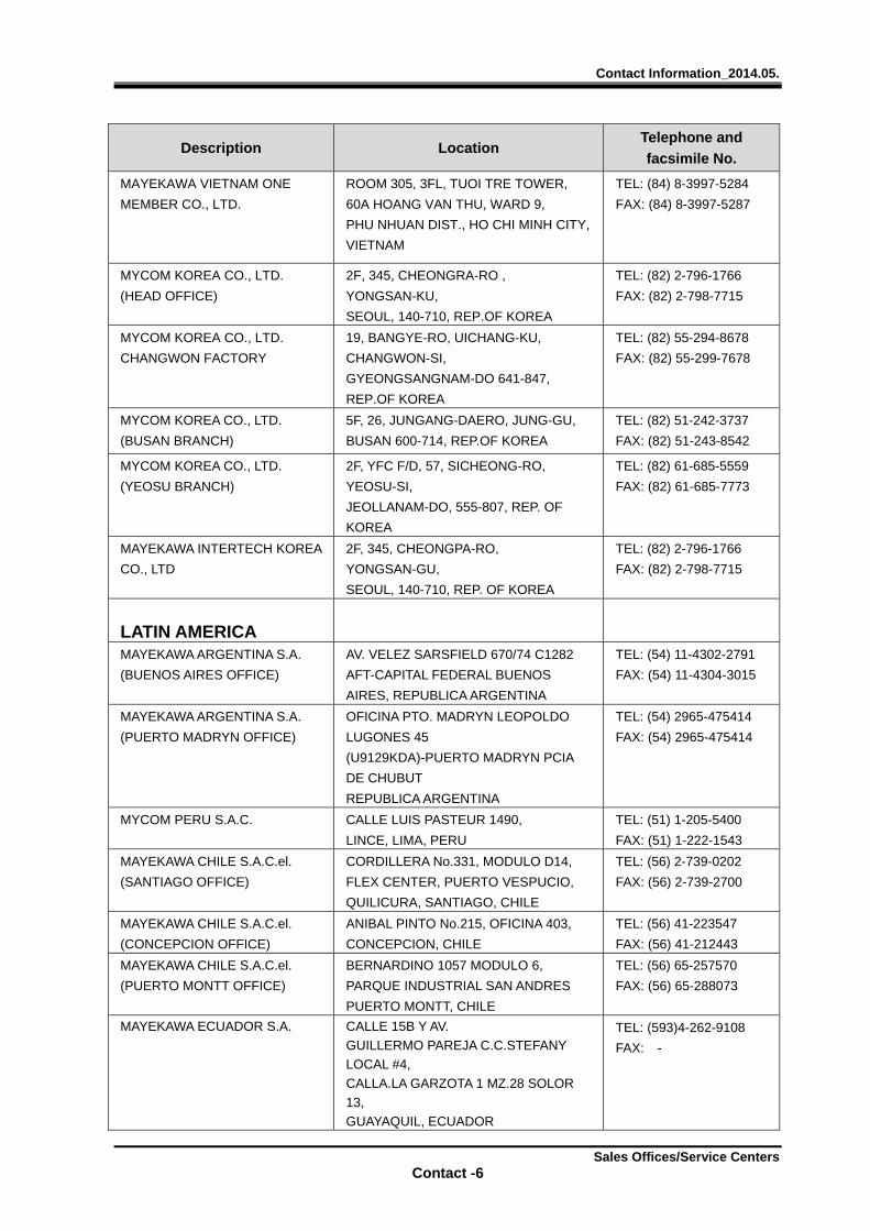
Contact Information_2014.05.
Sales Offices/Service Centers Contact -6
Description Location Telephone and
facsimile No.
MAYEKAWA VIETNAM ONE
MEMBER CO., LTD.
ROOM 305, 3FL, TUOI TRE TOWER,
60A HOANG VAN THU, WARD 9,
PHU NHUAN DIST., HO CHI MINH CITY,
VIETNAM
TEL: (84) 8-3997-5284
FAX: (84) 8-3997-5287
MYCOM KOREA CO., LTD.
(HEAD OFFICE)
2F, 345, CHEONGRA-RO ,
YONGSAN-KU,
SEOUL, 140-710, REP.OF KOREA
TEL: (82) 2-796-1766
FAX: (82) 2-798-7715
MYCOM KOREA CO., LTD.
CHANGWON FACTORY
19, BANGYE-RO, UICHANG-KU,
CHANGWON-SI,
GYEONGSANGNAM-DO 641-847,
REP.OF KOREA
TEL: (82) 55-294-8678
FAX: (82) 55-299-7678
MYCOM KOREA CO., LTD.
(BUSAN BRANCH)
5F, 26, JUNGANG-DAERO, JUNG-GU,
BUSAN 600-714, REP.OF KOREA
TEL: (82) 51-242-3737
FAX: (82) 51-243-8542
MYCOM KOREA CO., LTD.
(YEOSU BRANCH)
2F, YFC F/D, 57, SICHEONG-RO,
YEOSU-SI,
JEOLLANAM-DO, 555-807, REP. OF
KOREA
TEL: (82) 61-685-5559
FAX: (82) 61-685-7773
MAYEKAWA INTERTECH KOREA
CO., LTD
2F, 345, CHEONGPA-RO,
YONGSAN-GU,
SEOUL, 140-710, REP. OF KOREA
TEL: (82) 2-796-1766
FAX: (82) 2-798-7715
LATIN AMERICA
MAYEKAWA ARGENTINA S.A.
(BUENOS AIRES OFFICE)
AV. VELEZ SARSFIELD 670/74 C1282
AFT-CAPITAL FEDERAL BUENOS
AIRES, REPUBLICA ARGENTINA
TEL: (54) 11-4302-2791
FAX: (54) 11-4304-3015
MAYEKAWA ARGENTINA S.A.
(PUERTO MADRYN OFFICE)
OFICINA PTO. MADRYN LEOPOLDO
LUGONES 45
(U9129KDA)-PUERTO MADRYN PCIA
DE CHUBUT
REPUBLICA ARGENTINA
TEL: (54) 2965-475414
FAX: (54) 2965-475414
MYCOM PERU S.A.C. CALLE LUIS PASTEUR 1490,
LINCE, LIMA, PERU
TEL: (51) 1-205-5400
FAX: (51) 1-222-1543
MAYEKAWA CHILE S.A.C.el.
(SANTIAGO OFFICE)
CORDILLERA No.331, MODULO D14,
FLEX CENTER, PUERTO VESPUCIO,
QUILICURA, SANTIAGO, CHILE
TEL: (56) 2-739-0202
FAX: (56) 2-739-2700
MAYEKAWA CHILE S.A.C.el.
(CONCEPCION OFFICE)
ANIBAL PINTO No.215, OFICINA 403,
CONCEPCION, CHILE
TEL: (56) 41-223547
FAX: (56) 41-212443
MAYEKAWA CHILE S.A.C.el.
(PUERTO MONTT OFFICE)
BERNARDINO 1057 MODULO 6,
PARQUE INDUSTRIAL SAN ANDRES
PUERTO MONTT, CHILE
TEL: (56) 65-257570
FAX: (56) 65-288073
MAYEKAWA ECUADOR S.A. CALLE 15B Y AV.
GUILLERMO PAREJA C.C.STEFANY
LOCAL #4,
CALLA.LA GARZOTA 1 MZ.28 SOLOR
13,
GUAYAQUIL, ECUADOR
TEL: (593)4-262-9108
FAX: -
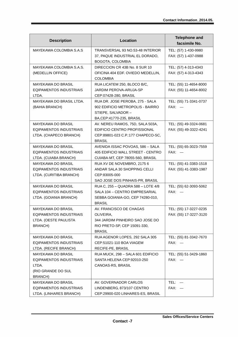
Contact Information_2014.05.
Sales Offices/Service Centers Contact -7
Description Location Telephone and
facsimile No.
MAYEKAWA COLOMBIA S.A.S TRANSVERSAL 93 NO.53-48 INTERIOR
37, PAQUE INDUSTRIAL EL DORADO,
BOGOTA, COLOMBIA
TEL: (57) 1-430-9980
FAX: (57) 1-437-0988
MAYEKAWA COLOMBIA S.A.S.
(MEDELLIN OFFICE)
DIRECCION CR 43B No. 8 SUR 10
OFICINA 404 EDF. OVIEDO MEDELLIN,
COLOMBIA
TEL: (57) 4-313-4343
FAX: (57) 4-313-4343
MAYEKAWA DO BRASIL
EQIPAMENTOS INDUSTRIAIS
LTDA.
RUA LICATEM 250, BLOCO B/C,
JARDIM PEROVA-ARUJA-SP
CEP:07428-280, BRASIL
TEL: (55) 11-4654-8000
FAX: (55) 11-4654-8002
MAYEKAWA DO BRASIL LTDA.
(BAHIA BRANCH)
RUA DR. JOSE PEROBA, 275 - SALA
902 EDIFICIO METROPOLIS - BAIRRO
STIEPE, SALVADOR –
BA,CEP:41770-235, BRASIL
TEL: (55) 71-3341-0737
FAX: —
MAYEKAWA DO BRASIL
EQIPAMENTOS INDUSTRIAIS
LTDA. (CHAPECO BRANCH)
AV. NEREU RAMOS, 75D, SALA 503A,
EDIFICIO CENTRO PROFISSIONAL
CEP:89801-023 C.P.:177 CHAPECO-SC,
BRASIL
TEL: (55) 49-3324-0681
FAX: (55) 49-3322-4241
MAYEKAWA DO BRASIL
EQIPAMENTOS INDUSTRIAIS
LTDA. (CUIABA BRANCH)
AVENIDA ISSAC POVOAS, 586 – SALA
405 EDIFICIO WALL STREET - CENTRO
CUIABA-MT, CEP 78055-560, BRASIL
TEL: (55) 65-3023-7559
FAX: —
MAYEKAWA DO BRASIL
EQIPAMENTOS INDUSTRIAIS
LTDA. (CURITIBA BRANCH)
RUA XV DE NOVEMBRO, 2175 6
ANDAR SALA 30 SHOPPING CELLI
CEP:83005-000
SAO JOSE DOS PINHAIS-PR, BRASIL
TEL: (55) 41-3383-1518
FAX: (55) 41-3383-1987
MAYEKAWA DO BRASIL
EQIPAMENTOS INDUSTRIAIS
LTDA. (GOIANIA BRANCH)
RUA C, 255 – QUADRA 588 – LOTE 4/8
SALA 104 – CENTRO EMPRESARIAL
SEBBA GOIANIA-GO, CEP 74280-010,
BRASIL
TEL: (55) 62-3093-5062
FAX: —
MAYEKAWA DO BRASIL
EQIPAMENTOS INDUSTRIAIS
LTDA. (OESTE PAULISTA
BRANCH)
AV. FRANCISCO DE CHAGAS
OLIVEIRA,
344 JARDIM PINHEIRO SAO JOSE DO
RIO PRETO-SP, CEP 15091-330,
BRASIL
TEL: (55) 17-3227-0235
FAX: (55) 17-3227-3120
MAYEKAWA DO BRASIL
EQIPAMENTOS INDUSTRIAIS
LTDA. (RECIFE BRANCH)
RUA AGENOR LOPES, 292 SALA 305
CEP:51021-110 BOA VIAGEM
RECIFE-PE, BRASIL
TEL: (55) 81-3342-7670
FAX: —
MAYEKAWA DO BRASIL
EQIPAMENTOS INDUSTRIAIS
LTDA.
(RIO GRANDE DO SUL
BRANCH)
RUA MUCK, 298 – SALA 601 EDIFICIO
SANTA HELENA CEP:92010-250
CANOAS-RS, BRASIL
TEL: (55) 51-3429-1860
FAX: —
MAYEKAWA DO BRASIL
EQIPAMENTOS INDUSTRIAIS
LTDA. (LINHARES BRANCH)
AV. GOVERNADOR CARLOS
LINDENBERG, 873/107 CENTRO
CEP:29900-020 LINHARES-ES, BRASIL
TEL: —
FAX: —
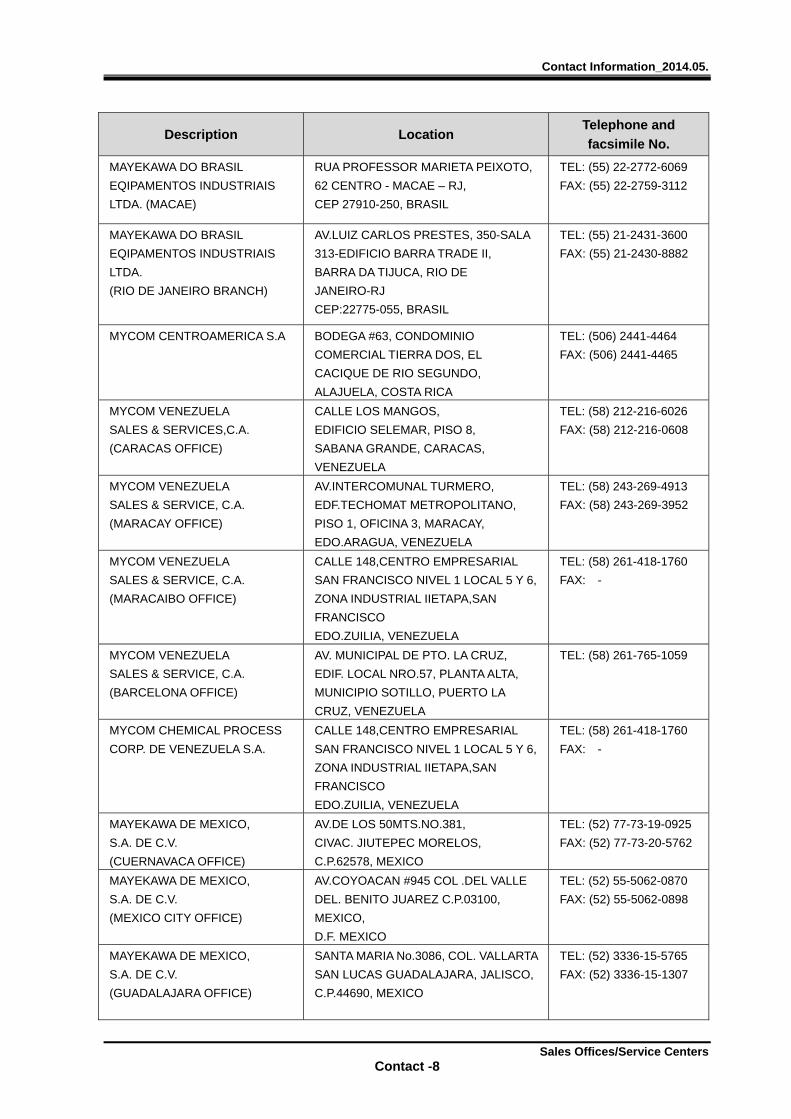
Contact Information_2014.05.
Sales Offices/Service Centers Contact -8
Description Location Telephone and
facsimile No.
MAYEKAWA DO BRASIL
EQIPAMENTOS INDUSTRIAIS
LTDA. (MACAE)
RUA PROFESSOR MARIETA PEIXOTO,
62 CENTRO - MACAE – RJ,
CEP 27910-250, BRASIL
TEL: (55) 22-2772-6069
FAX: (55) 22-2759-3112
MAYEKAWA DO BRASIL
EQIPAMENTOS INDUSTRIAIS
LTDA.
(RIO DE JANEIRO BRANCH)
AV.LUIZ CARLOS PRESTES, 350-SALA
313-EDIFICIO BARRA TRADE II,
BARRA DA TIJUCA, RIO DE
JANEIRO-RJ
CEP:22775-055, BRASIL
TEL: (55) 21-2431-3600
FAX: (55) 21-2430-8882
MYCOM CENTROAMERICA S.A BODEGA #63, CONDOMINIO
COMERCIAL TIERRA DOS, EL
CACIQUE DE RIO SEGUNDO,
ALAJUELA, COSTA RICA
TEL: (506) 2441-4464
FAX: (506) 2441-4465
MYCOM VENEZUELA
SALES & SERVICES,C.A.
(CARACAS OFFICE)
CALLE LOS MANGOS,
EDIFICIO SELEMAR, PISO 8,
SABANA GRANDE, CARACAS,
VENEZUELA
TEL: (58) 212-216-6026
FAX: (58) 212-216-0608
MYCOM VENEZUELA
SALES & SERVICE, C.A.
(MARACAY OFFICE)
AV.INTERCOMUNAL TURMERO,
EDF.TECHOMAT METROPOLITANO,
PISO 1, OFICINA 3, MARACAY,
EDO.ARAGUA, VENEZUELA
TEL: (58) 243-269-4913
FAX: (58) 243-269-3952
MYCOM VENEZUELA
SALES & SERVICE, C.A.
(MARACAIBO OFFICE)
CALLE 148,CENTRO EMPRESARIAL
SAN FRANCISCO NIVEL 1 LOCAL 5 Y 6,
ZONA INDUSTRIAL IIETAPA,SAN
FRANCISCO
EDO.ZUILIA, VENEZUELA
TEL: (58) 261-418-1760
FAX: -
MYCOM VENEZUELA
SALES & SERVICE, C.A.
(BARCELONA OFFICE)
AV. MUNICIPAL DE PTO. LA CRUZ,
EDIF. LOCAL NRO.57, PLANTA ALTA,
MUNICIPIO SOTILLO, PUERTO LA
CRUZ, VENEZUELA
TEL: (58) 261-765-1059
MYCOM CHEMICAL PROCESS
CORP. DE VENEZUELA S.A.
CALLE 148,CENTRO EMPRESARIAL
SAN FRANCISCO NIVEL 1 LOCAL 5 Y 6,
ZONA INDUSTRIAL IIETAPA,SAN
FRANCISCO
EDO.ZUILIA, VENEZUELA
TEL: (58) 261-418-1760
FAX: -
MAYEKAWA DE MEXICO,
S.A. DE C.V.
(CUERNAVACA OFFICE)
AV.DE LOS 50MTS.NO.381,
CIVAC. JIUTEPEC MORELOS,
C.P.62578, MEXICO
TEL: (52) 77-73-19-0925
FAX: (52) 77-73-20-5762
MAYEKAWA DE MEXICO,
S.A. DE C.V.
(MEXICO CITY OFFICE)
AV.COYOACAN #945 COL .DEL VALLE
DEL. BENITO JUAREZ C.P.03100,
MEXICO,
D.F. MEXICO
TEL: (52) 55-5062-0870
FAX: (52) 55-5062-0898
MAYEKAWA DE MEXICO,
S.A. DE C.V.
(GUADALAJARA OFFICE)
SANTA MARIA No.3086, COL. VALLARTA
SAN LUCAS GUADALAJARA, JALISCO,
C.P.44690, MEXICO
TEL: (52) 3336-15-5765
FAX: (52) 3336-15-1307
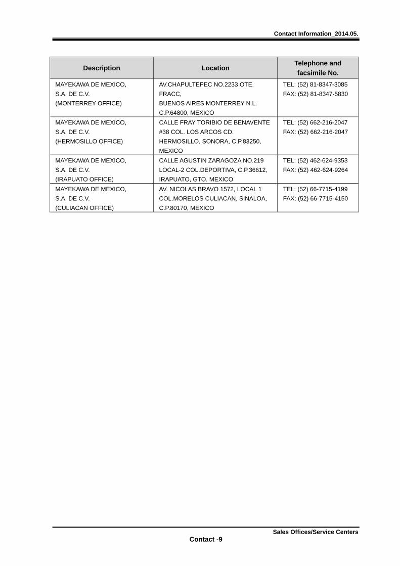
Contact Information_2014.05.
Sales Offices/Service Centers Contact -9
Description Location Telephone and
facsimile No.
MAYEKAWA DE MEXICO,
S.A. DE C.V.
(MONTERREY OFFICE)
AV.CHAPULTEPEC NO.2233 OTE.
FRACC,
BUENOS AIRES MONTERREY N.L.
C.P.64800, MEXICO
TEL: (52) 81-8347-3085
FAX: (52) 81-8347-5830
MAYEKAWA DE MEXICO,
S.A. DE C.V.
(HERMOSILLO OFFICE)
CALLE FRAY TORIBIO DE BENAVENTE
#38 COL. LOS ARCOS CD.
HERMOSILLO, SONORA, C.P.83250,
MEXICO
TEL: (52) 662-216-2047
FAX: (52) 662-216-2047
MAYEKAWA DE MEXICO,
S.A. DE C.V.
(IRAPUATO OFFICE)
CALLE AGUSTIN ZARAGOZA NO.219
LOCAL-2 COL.DEPORTIVA, C.P.36612,
IRAPUATO, GTO. MEXICO
TEL: (52) 462-624-9353
FAX: (52) 462-624-9264
MAYEKAWA DE MEXICO,
S.A. DE C.V.
(CULIACAN OFFICE)
AV. NICOLAS BRAVO 1572, LOCAL 1
COL.MORELOS CULIACAN, SINALOA,
C.P.80170, MEXICO
TEL: (52) 66-7715-4199
FAX: (52) 66-7715-4150
2205B0JE-DA-J-N_2014.05
MAYEKAWA MFG. CO., LTD. 3-14-15 Botan, Koto-ku, Tokyo 135-8482, Japan
TEL : 03-3642-8181 URL : http://www.mayekawa.com


![Condition Monitoring and Maintenance Program of Two Stage ... · Single-acting Reciprocating Compressor[2] Figure 3: Double-acting Reciprocating Compressor in V-arrangement.[2]](https://img.pdfslide.net/doc/110x75/5e6e5afd8fbbdf7ed300cf54/condition-monitoring-and-maintenance-program-of-two-stage-single-acting-reciprocating.jpg)