Embed Size (px)
Citation preview

Kinematics Statics Freedoms Screw Systems ISS and PSS Mobility Design Singularities
Screw Theory and its Applications inRobotics
Marco Carricato
Group of Robotics, Automation and BiomechanicsUniversity of Bologna
Italy
IFAC 2017 World Congress, Toulouse, France
Kinematics Statics Freedoms Screw Systems ISS and PSS Mobility Design Singularities
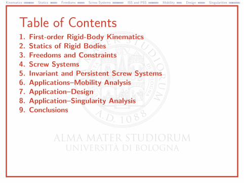
Table of Contents1. First-order Rigid-Body Kinematics2. Statics of Rigid Bodies3. Freedoms and Constraints4. Screw Systems5. Invariant and Persistent Screw Systems6. Applications–Mobility Analysis7. Application–Design8. Application–Singularity Analysis9. Conclusions
Kinematics Statics Freedoms Screw Systems ISS and PSS Mobility Design Singularities
First-order Rigid-Body Kinematics 3/72
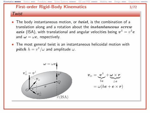
Twist
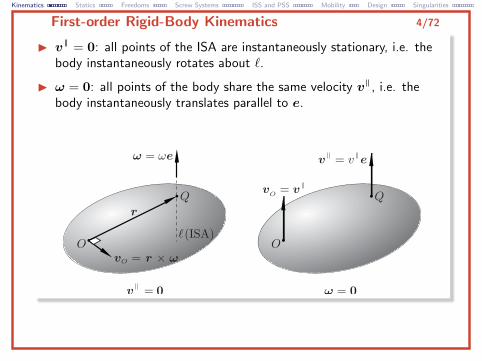
• The body instantaneous motion, or twist, is the combination of atranslation along and a rotation about the instantaneous screwaxis (ISA), with translational and angular velocities being v = v eand ω = ωe, respectively.
• The most general twist is an instantaneous helicoidal motion withpitch h = v /ω and amplitude ω.
vO = v︸︷︷︸e
+ω × r︸ ︷︷ ︸⊥e
= ω(he+ e× r)
Kinematics Statics Freedoms Screw Systems ISS and PSS Mobility Design Singularities
First-order Rigid-Body Kinematics 4/72
I v = 0: all points of the ISA are instantaneously stationary, i.e. thebody instantaneously rotates about `.
I ω = 0: all points of the body share the same velocity v , i.e. thebody instantaneously translates parallel to e.
Kinematics Statics Freedoms Screw Systems ISS and PSS Mobility Design Singularities
First-order Rigid-Body Kinematics 5/72
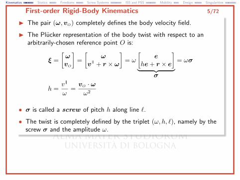
I The pair (ω,vO) completely defines the body velocity field.
I The Plucker representation of the body twist with respect to anarbitrarily-chosen reference point O is:
ξ =
[ωvO
]=
[ω
v + r × ω
]= ω
[e
he+ r × e
]︸ ︷︷ ︸
σ
= ωσ
h =v
ω=vO · ωω2
• σ is called a screw of pitch h along line `.
• The twist is completely defined by the triplet (ω, h, `), namely by thescrew σ and the amplitude ω.
Kinematics Statics Freedoms Screw Systems ISS and PSS Mobility Design Singularities
First-order Rigid-Body Kinematics 6/72
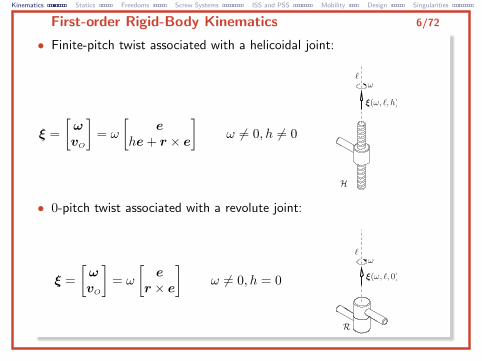
• Finite-pitch twist associated with a helicoidal joint:
ξ =
[ωvO
]= ω
[e
he+ r × e
]ω 6= 0, h 6= 0
• 0-pitch twist associated with a revolute joint:
ξ =
[ωvO
]= ω
[e
r × e
]ω 6= 0, h = 0
Kinematics Statics Freedoms Screw Systems ISS and PSS Mobility Design Singularities
First-order Rigid-Body Kinematics 7/72
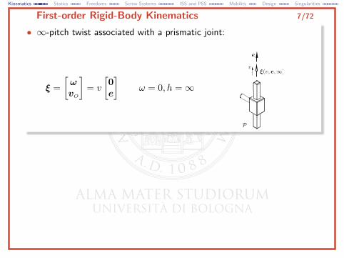
• ∞-pitch twist associated with a prismatic joint:
ξ =
[ωvO
]= v
[0e
]ω = 0, h =∞
Kinematics Statics Freedoms Screw Systems ISS and PSS Mobility Design Singularities
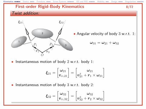
First-order Rigid-Body Kinematics 8/72
Twist addition:
1
2
3
• Angular velocity of body 3 w.r.t. 1:
ω31 = ω21 + ω32
• Instantaneous motion of body 2 w.r.t. body 1:
ξ21 =
[ω21
vO,21
]=
[ω21
v21 + r1 × ω21
]• Instantaneous motion of body 3 w.r.t. body 2:
ξ32 =
[ω32
vO,32
]=
[ω32
v32 + r2 × ω32
]
Kinematics Statics Freedoms Screw Systems ISS and PSS Mobility Design Singularities
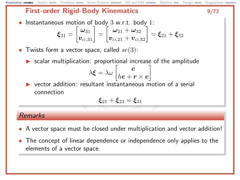
First-order Rigid-Body Kinematics 9/72
• Instantaneous motion of body 3 w.r.t. body 1:
ξ31 =
[ω31
vO,31
]=
[ω21 + ω32
vO,21 + vO,32
]= ξ21 + ξ32
• Twists form a vector space, called se(3):
I scalar multiplication: proportional increase of the amplitude
λξ = λω
[e
he+ r × e
]I vector addition: resultant instantaneous motion of a serial
connectionξ21 + ξ23 = ξ31
Remarks
• A vector space must be closed under multiplication and vector addition!
• The concept of linear dependence or independence only applies to theelements of a vector space.
Kinematics Statics Freedoms Screw Systems ISS and PSS Mobility Design Singularities
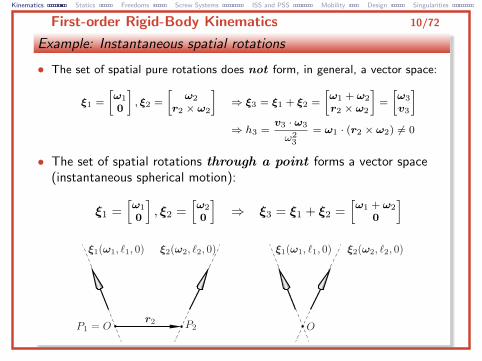
First-order Rigid-Body Kinematics 10/72
Example: Instantaneous spatial rotations
• The set of spatial pure rotations does not form, in general, a vector space:
ξ1 =
[ω1
0
], ξ2 =
[ω2
r2 × ω2
]⇒ ξ3 = ξ1 + ξ2 =
[ω1 + ω2
r2 × ω2
]=
[ω3
v3
]⇒ h3 =
v3 · ω3
ω23
= ω1 · (r2 × ω2) 6= 0
• The set of spatial rotations through a point forms a vector space(instantaneous spherical motion):
ξ1 =[ω1
0
], ξ2 =
[ω2
0
]⇒ ξ3 = ξ1 + ξ2 =
[ω1 + ω2
0
]
Kinematics Statics Freedoms Screw Systems ISS and PSS Mobility Design Singularities
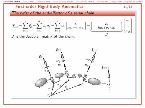
First-order Rigid-Body Kinematics 11/72
The twist of the end-effector of a serial chain
ξEE =
µ∑i=1
ξi=
µ∑i=1
ωiσi=
µ∑i=1
ωi
[ei
hei+ri×ei
]=[· · · ei
hei+ri×ei· · ·]
︸ ︷︷ ︸J
ω1
...ωµ
J is the Jacobian matrix of the chain.
Kinematics Statics Freedoms Screw Systems ISS and PSS Mobility Design Singularities
First-order Rigid-Body Kinematics 12/72
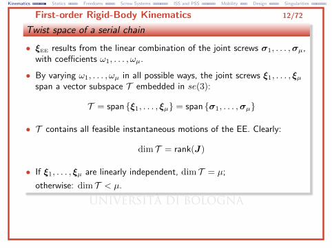
Twist space of a serial chain
• ξEE results from the linear combination of the joint screws σ1, . . . ,σµ,with coefficients ω1, . . . , ωµ.
• By varying ω1, . . . , ωµ in all possible ways, the joint screws ξ1, . . . , ξµspan a vector subspace T embedded in se(3):
T = span {ξ1, . . . , ξµ} = span {σ1, . . . ,σµ}
• T contains all feasible instantaneous motions of the EE. Clearly:
dim T = rank(J)
• If ξ1, . . . , ξµ are linearly independent, dim T = µ;
otherwise: dim T < µ.
Kinematics Statics Freedoms Screw Systems ISS and PSS Mobility Design Singularities
Statics of Rigid Bodies 13/72
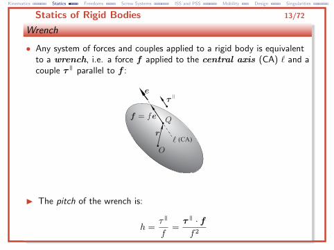
Wrench
• Any system of forces and couples applied to a rigid body is equivalentto a wrench, i.e. a force f applied to the central axis (CA) ` and acouple τ parallel to f :
I The pitch of the wrench is:
h =τ
f=τ · ff2
Kinematics Statics Freedoms Screw Systems ISS and PSS Mobility Design Singularities
Statics of Rigid Bodies 14/72
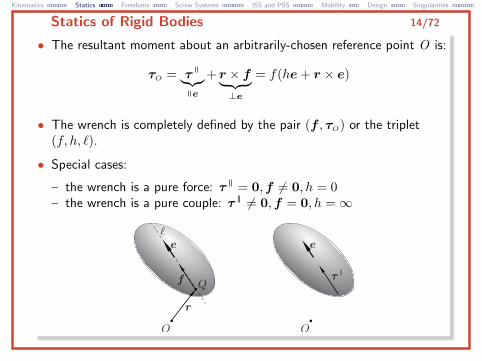
• The resultant moment about an arbitrarily-chosen reference point O is:
τO = τ︸︷︷︸e
+ r × f︸ ︷︷ ︸⊥e
= f(he+ r × e)
• The wrench is completely defined by the pair (f , τO) or the triplet(f, h, `).
• Special cases:
– the wrench is a pure force: τ = 0,f 6= 0, h = 0– the wrench is a pure couple: τ 6= 0,f = 0, h =∞
Kinematics Statics Freedoms Screw Systems ISS and PSS Mobility Design Singularities
Statics of Rigid Bodies 15/72
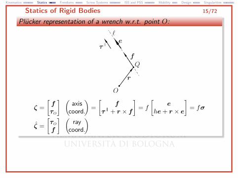
Plucker representation of a wrench w.r.t. point O:
ζ =
[fτO
] (axis
coord.
)=
[f
τ + r × f
]= f
[e
he+ r × e
]= fσ
ζ =
[τO
f
] (ray
coord.
)
Kinematics Statics Freedoms Screw Systems ISS and PSS Mobility Design Singularities
Statics of Rigid Bodies 16/72
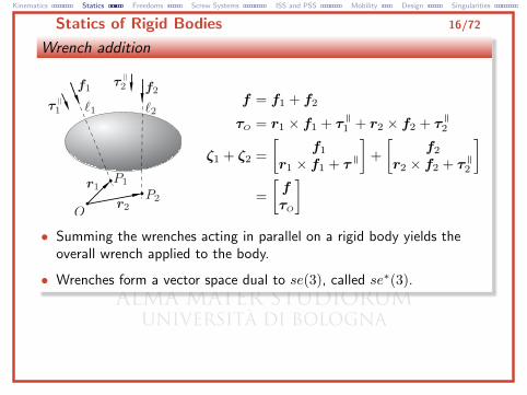
Wrench addition
f = f1 + f2
τO = r1 × f1 + τ1 + r2 × f2 + τ2
ζ1 + ζ2 =
[f1
r1 × f1 + τ
]+
[f2
r2 × f2 + τ2
]=
[fτO
]• Summing the wrenches acting in parallel on a rigid body yields the
overall wrench applied to the body.
• Wrenches form a vector space dual to se(3), called se∗(3).
Kinematics Statics Freedoms Screw Systems ISS and PSS Mobility Design Singularities
Statics of Rigid Bodies 17/72
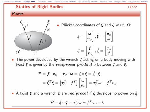
Power:
• Plucker coordinates of ξ and ζ w.r.t. O:
ξ =
[ωvO
], ξ =
[vO
ω
]
ζ =
[fτO
], ζ =
[τO
f
]• The power developed by the wrench ζ acting on a body moving with
twist ξ is given by the reciprocal product ◦ between ζ and ξ:
P = f · vO + τO · ω = ζ ◦ ξ = ζ · ξ
= ζT ξ =[τTO fT
] [ωvO
]= τTO ω + fTvO
• A twist ξ and a wrench ζ are reciprocal if ζ develops no power on ξ:
P = ξ ◦ ζ = τTO ω + fTvO = 0
Kinematics Statics Freedoms Screw Systems ISS and PSS Mobility Design Singularities
Statics of Rigid Bodies 18/72
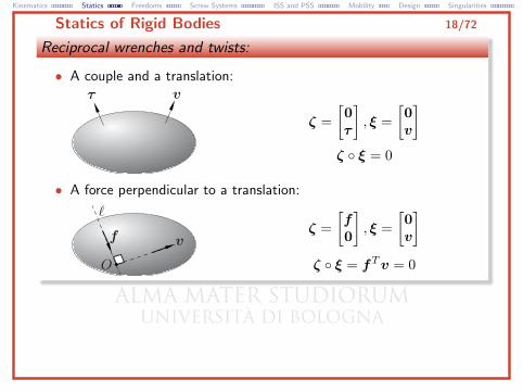
Reciprocal wrenches and twists:
• A couple and a translation:
ζ =
[0τ
], ξ =
[0v
]ζ ◦ ξ = 0
• A force perpendicular to a translation:
ζ =
[f0
], ξ =
[0v
]ζ ◦ ξ = fTv = 0
Kinematics Statics Freedoms Screw Systems ISS and PSS Mobility Design Singularities
Statics of Rigid Bodies 19/72
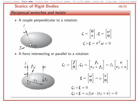
Reciprocal wrenches and twists:
• A couple perpendicular to a rotation:
ζ =
[0τ
], ξ =
[ω0
]ζ ◦ ξ = τTω = 0
• A force intersecting or parallel to a rotation:
ζ1 =
[f0
], ζ2 =
[f2
r2 × f2
]= f2
[e
r2 × e
]
ξ =
[ω0
]= ω
[e0
]ζ1 ◦ ξ = 0
ζ2 ◦ ξ = ωf2e · (r2 × e) = 0
Kinematics Statics Freedoms Screw Systems ISS and PSS Mobility Design Singularities
Freedoms and Constraints 20/72
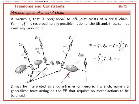
Wrench space of a serial chain
A wrench ζ that is reciprocal to all joint twists of a serial chain,ξ1, · · · , ξµ, is reciprocal to any possible motion of the EE and, thus, cannotexert any work on it:
P = ζ ◦ ξEE = ζ ◦µ∑i=1
ξi
=
µ∑i=1
ζ ◦ ξi = 0
ζ may be interpreted as a constraint or reaction wrench, namely ageneralized force acting on the EE that requires no motor actions to bebalanced.
Kinematics Statics Freedoms Screw Systems ISS and PSS Mobility Design Singularities
Freedoms and Constraints 21/72
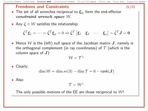
• The set of all wrenches reciprocal to ξEE form the end-effectorconstraint wrench space W.
• Any ζ ∈ W satisfies the relationship:
ζT ξ1 = · · · = ζT ξµ = 0⇔ ζT[ξ1 ξ2 · · · ξµ
]= ζTJ = 0
• Hence W is the (left) null space of the Jacobian matrix J , namely isthe orthogonal complement (in ray coordinates) of T (which is thecolumn space of J):
W = T ⊥
• Clearly:dimW = dim se(3)− dim T = 6− rank(J)
• Also:T =W⊥
The only possible motions of the EE are those reciprocal to W!
Kinematics Statics Freedoms Screw Systems ISS and PSS Mobility Design Singularities
Freedoms and Constraints 22/72
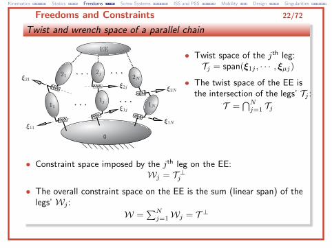
Twist and wrench space of a parallel chain
• Twist space of the jth leg:Tj = span(ξ1j , · · · , ξµj)
• The twist space of the EE isthe intersection of the legs’ Tj :
T =⋂Nj=1 Tj
• Constraint space imposed by the jth leg on the EE:Wj = T ⊥j
• The overall constraint space on the EE is the sum (linear span) of thelegs’ Wj :
W =∑Nj=1Wj = T ⊥
Kinematics Statics Freedoms Screw Systems ISS and PSS Mobility Design Singularities
Freedoms and Constraints 23/72
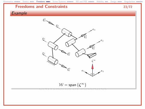
Example
W = span {ζ∞}
Kinematics Statics Freedoms Screw Systems ISS and PSS Mobility Design Singularities
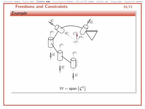
Freedoms and Constraints 24/72
Example
W = span{ζ0}
Kinematics Statics Freedoms Screw Systems ISS and PSS Mobility Design Singularities
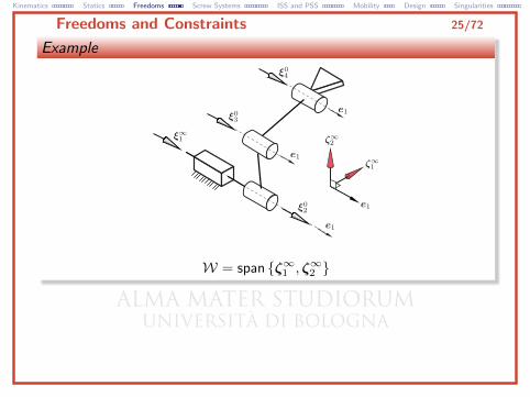
Freedoms and Constraints 25/72
Example
W = span {ζ∞1 , ζ∞2 }
Kinematics Statics Freedoms Screw Systems ISS and PSS Mobility Design Singularities
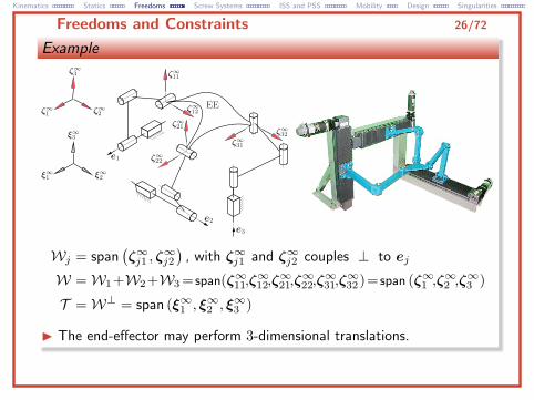
Freedoms and Constraints 26/72
Example
Wj = span(ζ∞j1 , ζ
∞j2
), with ζ∞j1 and ζ∞j2 couples ⊥ to ej
W =W1+W2+W3 = span(ζ∞11,ζ∞12,ζ∞21,ζ∞22,ζ∞31,ζ∞32)= span (ζ∞1 ,ζ
∞2 ,ζ∞3 )
T =W⊥ = span (ξ∞1 , ξ∞2 , ξ
∞3 )
I The end-effector may perform 3-dimensional translations.
Kinematics Statics Freedoms Screw Systems ISS and PSS Mobility Design Singularities
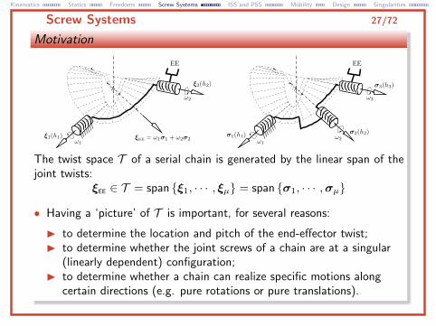
Screw Systems 27/72
Motivation
The twist space T of a serial chain is generated by the linear span of thejoint twists:
ξEE ∈ T = span {ξ1, · · · , ξµ} = span {σ1, · · · ,σµ}
• Having a ‘picture’ of T is important, for several reasons:
I to determine the location and pitch of the end-effector twist;I to determine whether the joint screws of a chain are at a singular
(linearly dependent) configuration;I to determine whether a chain can realize specific motions along
certain directions (e.g. pure rotations or pure translations).
Kinematics Statics Freedoms Screw Systems ISS and PSS Mobility Design Singularities
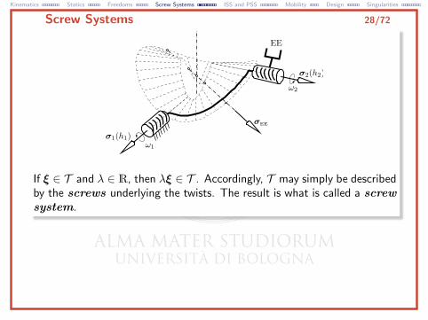
Screw Systems 28/72
If ξ ∈ T and λ ∈ R, then λξ ∈ T . Accordingly, T may simply be describedby the screws underlying the twists. The result is what is called a screwsystem.
Kinematics Statics Freedoms Screw Systems ISS and PSS Mobility Design Singularities
Screw Systems 29/72
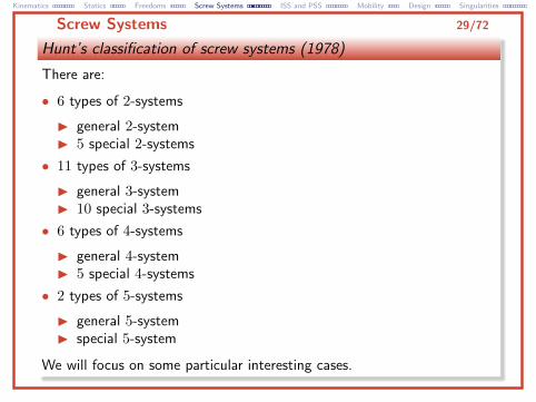
Hunt’s classification of screw systems (1978)
There are:
• 6 types of 2-systems
I general 2-systemI 5 special 2-systems
• 11 types of 3-systems
I general 3-systemI 10 special 3-systems
• 6 types of 4-systems
I general 4-systemI 5 special 4-systems
• 2 types of 5-systems
I general 5-systemI special 5-system
We will focus on some particular interesting cases.
Kinematics Statics Freedoms Screw Systems ISS and PSS Mobility Design Singularities
2-Systems 30/72
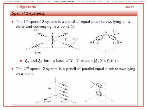
Special 2-systems:
• The 1st special 2-system is a pencil of equal-pitch screws lying on aplane and converging in a point O.
I ξα and ξβ form a basis of T : T = span {ξα(0), ξβ(0)}.
• The 2nd special 2-system is a pencil of parallel equal-pitch screws lyingon a plane.
Kinematics Statics Freedoms Screw Systems ISS and PSS Mobility Design Singularities
2-Systems 31/72
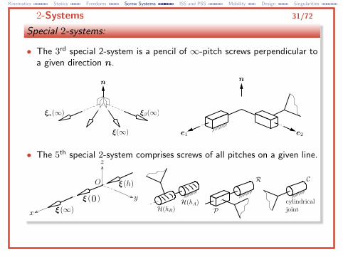
Special 2-systems:
• The 3rd special 2-system is a pencil of ∞-pitch screws perpendicular toa given direction n.
• The 5th special 2-system comprises screws of all pitches on a given line.
Kinematics Statics Freedoms Screw Systems ISS and PSS Mobility Design Singularities
Special 3-systems 32/72
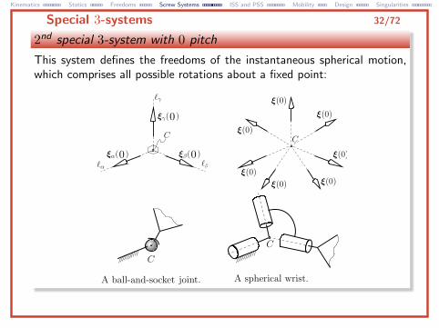
2nd special 3-system with 0 pitch
This system defines the freedoms of the instantaneous spherical motion,which comprises all possible rotations about a fixed point:
Kinematics Statics Freedoms Screw Systems ISS and PSS Mobility Design Singularities
Special 3-systems 33/72
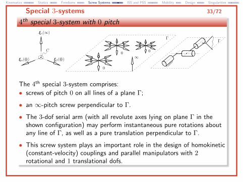
4th special 3-system with 0 pitch
The 4th special 3-system comprises:
• screws of pitch 0 on all lines of a plane Γ;
• an ∞-pitch screw perpendicular to Γ.
• The 3-dof serial arm (with all revolute axes lying on plane Γ in theshown configuration) may perform instantaneous pure rotations aboutany line of Γ, as well as a pure translation perpendicular to Γ.
• This screw system plays an important role in the design of homokinetic(constant-velocity) couplings and parallel manipulators with 2rotational and 1 translational dofs.
Kinematics Statics Freedoms Screw Systems ISS and PSS Mobility Design Singularities
Special 3-systems 34/72
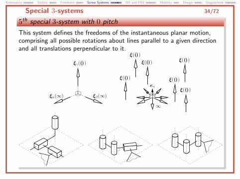
5th special 3-system with 0 pitch
This system defines the freedoms of the instantaneous planar motion,comprising all possible rotations about lines parallel to a given directionand all translations perpendicular to it.
Kinematics Statics Freedoms Screw Systems ISS and PSS Mobility Design Singularities
Special 3-systems 35/72
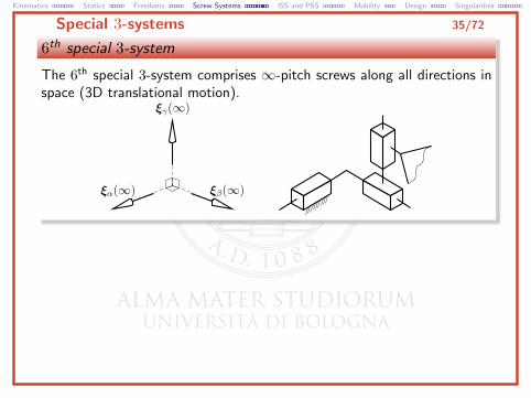
6th special 3-system
The 6th special 3-system comprises ∞-pitch screws along all directions inspace (3D translational motion).
Kinematics Statics Freedoms Screw Systems ISS and PSS Mobility Design Singularities
4-systems 36/72
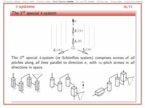
The 3rd special 4-system
The 3rd special 4-system (or Schonflies system) comprises screws of allpitches along all lines parallel to direction e, with ∞-pitch screws in alldirections in space.

Kinematics Statics Freedoms Screw Systems ISS and PSS Mobility Design Singularities
5-systems 37/72
Special 5-system
The special 5-system comprises:
• ∞-pitch screws along all directions in space;
• finite-pitch (including 0) screws on all lines perpendicular to a givendirection e.
Kinematics Statics Freedoms Screw Systems ISS and PSS Mobility Design Singularities
Invariant Screw Systems (ISSs) 38/72
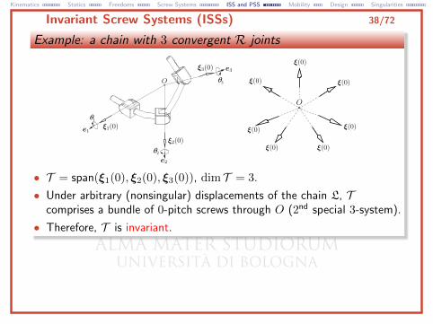
Example: a chain with 3 convergent R joints
• T = span(ξ1(0), ξ2(0), ξ3(0)), dim T = 3.
• Under arbitrary (nonsingular) displacements of the chain L, Tcomprises a bundle of 0-pitch screws through O (2nd special 3-system).
• Therefore, T is invariant.
Kinematics Statics Freedoms Screw Systems ISS and PSS Mobility Design Singularities
Invariant Screw Systems (ISSs) 39/72
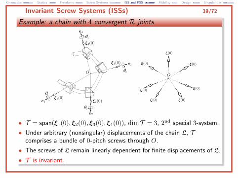
Example: a chain with 4 convergent R joints
• T = span(ξ1(0), ξ2(0), ξ3(0), ξ4(0)), dim T = 3, 2nd special 3-system.
• Under arbitrary (nonsingular) displacements of the chain L, Tcomprises a bundle of 0-pitch screws through O.
• The screws of L remain linearly dependent for finite displacements of L.
• T is invariant.
Kinematics Statics Freedoms Screw Systems ISS and PSS Mobility Design Singularities
Invariant Screw Systems (ISSs) 40/72
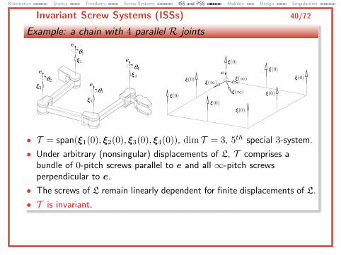
Example: a chain with 4 parallel R joints
• T = span(ξ1(0), ξ2(0), ξ3(0), ξ4(0)), dim T = 3, 5th special 3-system.
• Under arbitrary (nonsingular) displacements of L, T comprises abundle of 0-pitch screws parallel to e and all ∞-pitch screwsperpendicular to e.
• The screws of L remain linearly dependent for finite displacements of L.
• T is invariant.
Kinematics Statics Freedoms Screw Systems ISS and PSS Mobility Design Singularities
Invariant Screw Systems (ISSs) 41/72
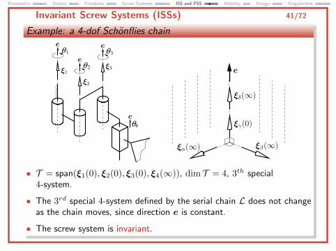
Example: a 4-dof Schonflies chain
• T = span(ξ1(0), ξ2(0), ξ3(0), ξ4(∞)), dim T = 4, 3th special4-system.
• The 3rd special 4-system defined by the serial chain L does not changeas the chain moves, since direction e is constant.
• The screw system is invariant.
Kinematics Statics Freedoms Screw Systems ISS and PSS Mobility Design Singularities
Invariant Screw Systems (ISSs) 42/72
Invariant screw systems (ISSs):
• Whichever finite displacement is assigned around the joint screws of L(besides a discrete number of possibly singular configurations), thescrew system instantaneously generated is invariant, thus preserving:
I dimension,I type,I shape,I pose.
Kinematics Statics Freedoms Screw Systems ISS and PSS Mobility Design Singularities
Invariant Screw Systems (ISSs) 43/72
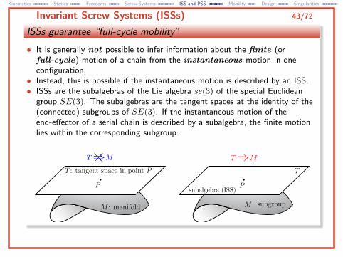
ISSs guarantee “full-cycle mobility”
• It is generally not possible to infer information about the finite (orfull-cycle) motion of a chain from the instantaneous motion in oneconfiguration.
• Instead, this is possible if the instantaneous motion is described by an ISS.• ISSs are the subalgebras of the Lie algebra se(3) of the special Euclidean
group SE(3). The subalgebras are the tangent spaces at the identity of the(connected) subgroups of SE(3). If the instantaneous motion of theend-effector of a serial chain is described by a subalgebra, the finite motionlies within the corresponding subgroup.
Kinematics Statics Freedoms Screw Systems ISS and PSS Mobility Design Singularities
Invariant Screw Systems (ISSs) 44/72
Example
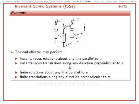
• The end-effector may perform:
I instantaneous rotations about any line parallel to eI instantaneous translations along any direction perpendicular to e
⇓I finite rotations about any line parallel to eI finite translations along any direction perpendicular to e
Kinematics Statics Freedoms Screw Systems ISS and PSS Mobility Design Singularities
Invariant Screw Systems (ISSs) 45/72
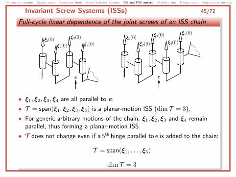
Full-cycle linear dependence of the joint screws of an ISS chain
• ξ1, ξ2, ξ3, ξ4 are all parallel to e;
• T = span(ξ1, ξ2, ξ3, ξ4) is a planar-motion ISS (dim T = 3).
• For generic arbitrary motions of the chain, ξ1, ξ2, ξ3 and ξ4 remainparallel, thus forming a planar-motion ISS.
• T does not change even if a 5th hinge parallel toe is added to the chain:
T = span(ξ1, . . . , ξ5)
dim T = 3
Kinematics Statics Freedoms Screw Systems ISS and PSS Mobility Design Singularities
Invariant Screw Systems (ISSs) 46/72
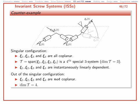
Counter-example
Singular configuration:
I ξ1, ξ2, ξ3 and ξ4 are all coplanar.
I T = span(ξ1, ξ2, ξ3, ξ4) is a 4th special 3-system (dim T = 3).
I ξ1, ξ2, ξ3 and ξ4 are instantaneously linearly dependent.
Out of the singular configuration:
I ξ1, ξ2, ξ3 and ξ4 are not coplanar.
I dim T = 4.
Kinematics Statics Freedoms Screw Systems ISS and PSS Mobility Design Singularities
Persistent Screw Systems (PSSs) 47/72
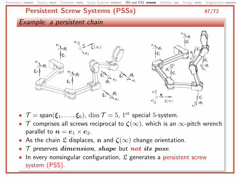
Example: a persistent chain
• T = span(ξ1, . . . , ξ6), dim T = 5, 1st special 5-system.
• T comprises all screws reciprocal to ζ(∞), which is an ∞-pitch wrenchparallel to n = e1 × e2.
• As the chain L displaces, n and ζ(∞) change orientation.
• T preserves dimension, shape but not its pose.
• In every nonsingular configuration, L generates a persistent screwsystem (PSS).
Kinematics Statics Freedoms Screw Systems ISS and PSS Mobility Design Singularities
Application: Mobility Analysis 48/72
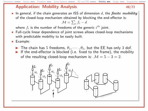
• In general, if the chain generates an ISS of dimension d, the finite mobilityof the closed-loop mechanism obtained by blocking the end-effector is:
M =∑i fi − d
where fi is the number of freedoms of the generic ith joint.• Full-cycle linear dependence of joint screws allows closed-loop mechanisms
with predictable mobility to be easily built.
• Example:
I The chain has 5 freedoms, θ1, · · · , θ5, but the EE has only 3 dof.I If the end-effector is blocked (i.e. fixed to the frame), the mobility
of the resulting closed-loop mechanism is: M = 5− 3 = 2.
Kinematics Statics Freedoms Screw Systems ISS and PSS Mobility Design Singularities
Application: Mobility Analysis 49/72
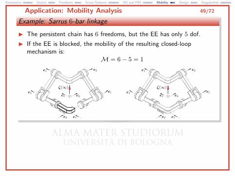
Example: Sarrus 6-bar linkage
I The persistent chain has 6 freedoms, but the EE has only 5 dof.
I If the EE is blocked, the mobility of the resulting closed-loopmechanism is:
M = 6− 5 = 1
Kinematics Statics Freedoms Screw Systems ISS and PSS Mobility Design Singularities
Application: Mobility Analysis 50/72
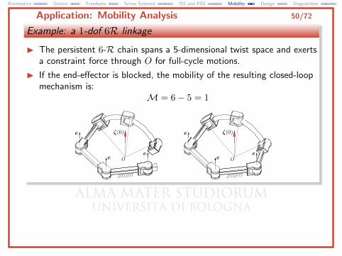
Example: a 1-dof 6R linkage
I The persistent 6-R chain spans a 5-dimensional twist space and exertsa constraint force through O for full-cycle motions.
I If the end-effector is blocked, the mobility of the resulting closed-loopmechanism is:
M = 6− 5 = 1
Kinematics Statics Freedoms Screw Systems ISS and PSS Mobility Design Singularities
Application: Mobility Analysis 51/72
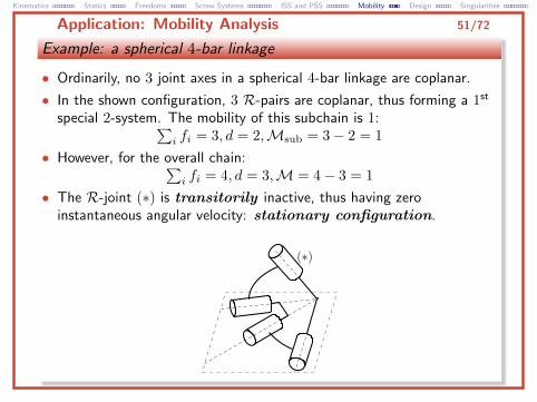
Example: a spherical 4-bar linkage
• Ordinarily, no 3 joint axes in a spherical 4-bar linkage are coplanar.
• In the shown configuration, 3 R-pairs are coplanar, thus forming a 1st
special 2-system. The mobility of this subchain is 1:∑i fi = 3, d = 2,Msub = 3− 2 = 1
• However, for the overall chain:∑i fi = 4, d = 3,M = 4− 3 = 1
• The R-joint (∗) is transitorily inactive, thus having zeroinstantaneous angular velocity: stationary configuration.
Kinematics Statics Freedoms Screw Systems ISS and PSS Mobility Design Singularities
Application: Mobility Analysis 52/72
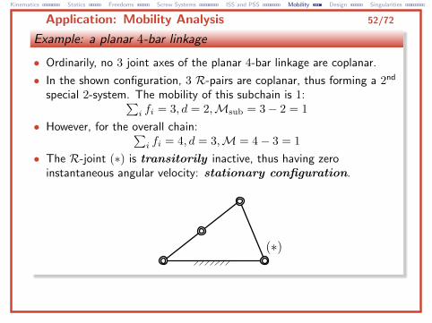
Example: a planar 4-bar linkage
• Ordinarily, no 3 joint axes of the planar 4-bar linkage are coplanar.
• In the shown configuration, 3 R-pairs are coplanar, thus forming a 2nd
special 2-system. The mobility of this subchain is 1:∑i fi = 3, d = 2,Msub = 3− 2 = 1
• However, for the overall chain:∑i fi = 4, d = 3,M = 4− 3 = 1
• The R-joint (∗) is transitorily inactive, thus having zeroinstantaneous angular velocity: stationary configuration.
Kinematics Statics Freedoms Screw Systems ISS and PSS Mobility Design Singularities
Application: Design 53/72
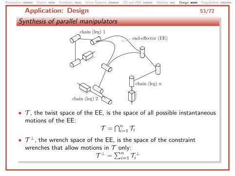
Synthesis of parallel manipulators
• T , the twist space of the EE, is the space of all possible instantaneousmotions of the EE:
T =⋂ni=1 Ti
• T ⊥, the wrench space of the EE, is the space of the constraintwrenches that allow motions in T only:
T ⊥ =∑ni=1 T ⊥i
Kinematics Statics Freedoms Screw Systems ISS and PSS Mobility Design Singularities
Application: Design 54/72
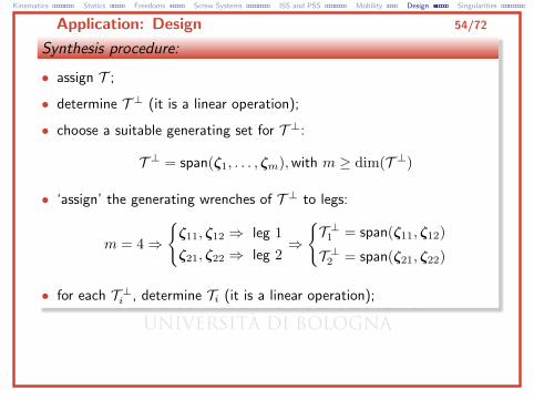
Synthesis procedure:
• assign T ;
• determine T ⊥ (it is a linear operation);
• choose a suitable generating set for T ⊥:
T ⊥ = span(ζ1, . . . , ζm),with m ≥ dim(T ⊥)
• ‘assign’ the generating wrenches of T ⊥ to legs:
m = 4⇒
{ζ11, ζ12 ⇒ leg 1
ζ21, ζ22 ⇒ leg 2⇒
{T ⊥1 = span(ζ11, ζ12)
T ⊥2 = span(ζ21, ζ22)
• for each T ⊥i , determine Ti (it is a linear operation);
Kinematics Statics Freedoms Screw Systems ISS and PSS Mobility Design Singularities
Application: Design 55/72
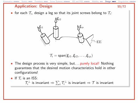
• for each Ti, design a leg so that its joint screws belong to Ti:
Ti = span(ξi1, ξi2, . . . , ξiµ)
• The design process is very simple, but. . . purely local! Nothingguarantees that the desired motion characteristics hold in otherconfigurations!
• If Ti is an ISS:T ⊥i is invariant ⇒
∑i T ⊥i is invariant ⇒ T is invariant
Kinematics Statics Freedoms Screw Systems ISS and PSS Mobility Design Singularities
Application: Design 56/72
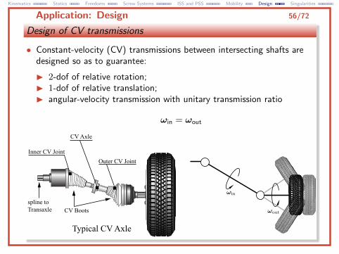
Design of CV transmissions
• Constant-velocity (CV) transmissions between intersecting shafts aredesigned so as to guarantee:
I 2-dof of relative rotation;I 1-dof of relative translation;I angular-velocity transmission with unitary transmission ratio
ωin = ωout
Kinematics Statics Freedoms Screw Systems ISS and PSS Mobility Design Singularities
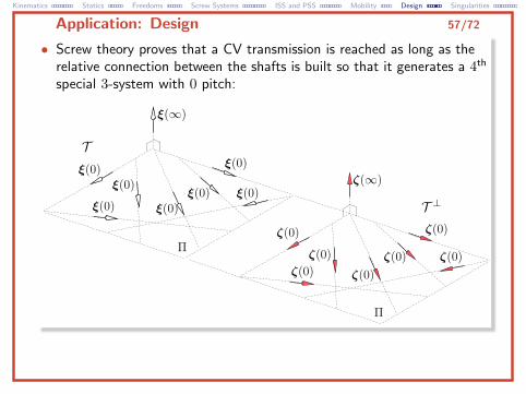
Application: Design 57/72
• Screw theory proves that a CV transmission is reached as long as therelative connection between the shafts is built so that it generates a 4th
special 3-system with 0 pitch:

Kinematics Statics Freedoms Screw Systems ISS and PSS Mobility Design Singularities
Application: Design 58/72
• The classic Rzeppa joint, for instance, is kinematically equivalent to aparallel mechanism with µ RSR architecture (µ ≥ 3):
Kinematics Statics Freedoms Screw Systems ISS and PSS Mobility Design Singularities
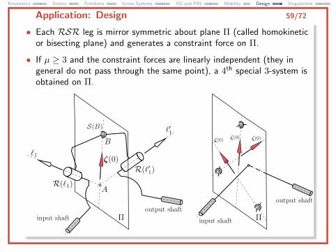
Application: Design 59/72
• Each RSR leg is mirror symmetric about plane Π (called homokineticor bisecting plane) and generates a constraint force on Π.
• If µ ≥ 3 and the constraint forces are linearly independent (they ingeneral do not pass through the same point), a 4th special 3-system isobtained on Π.
Kinematics Statics Freedoms Screw Systems ISS and PSS Mobility Design Singularities
Application: Singularity Analysis 60/72
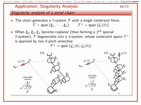
Singularity analysis of a serial chain:
• The chain generates a 5-system T with a single constraint force:T = span {ξ1, · · · , ξ5} T ⊥ = span {ζ1(0)}
• When ξ2, ξ3, ξ4 become coplanar (thus forming a 2nd special2-system), T degenerates into a 4-system, whose constraint space T ⊥is spanned by two 0-pitch wrenches:
T ⊥ = span {ζ1(0), ζ2(0)}
Kinematics Statics Freedoms Screw Systems ISS and PSS Mobility Design Singularities
Application: Singularity Analysis 61/72
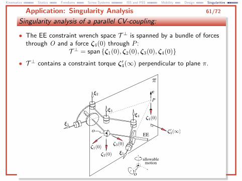
Singularity analysis of a parallel CV-coupling:
• The EE constraint wrench space T ⊥ is spanned by a bundle of forcesthrough O and a force ζ4(0) through P :
T ⊥ = span {ζ1(0), ζ2(0), ζ3(0), ζ4(0)}
• T ⊥ contains a constraint torque ζ′4(∞) perpendicular to plane π.
Kinematics Statics Freedoms Screw Systems ISS and PSS Mobility Design Singularities
Application: Singularity Analysis 62/72
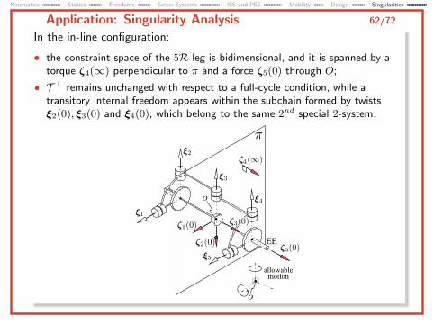
In the in-line configuration:
• the constraint space of the 5R leg is bidimensional, and it is spanned by atorque ζ4(∞) perpendicular to π and a force ζ5(0) through O;
• T ⊥ remains unchanged with respect to a full-cycle condition, while atransitory internal freedom appears within the subchain formed by twistsξ2(0), ξ3(0) and ξ4(0), which belong to the same 2nd special 2-system.
Kinematics Statics Freedoms Screw Systems ISS and PSS Mobility Design Singularities
Application: Singularity Analysis 63/72
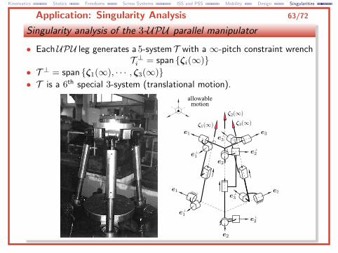
Singularity analysis of the 3-UPU parallel manipulator
• EachUPU leg generates a 5-systemT with a ∞-pitch constraint wrenchT ⊥i = span {ζi(∞)}
• T ⊥ = span {ζ1(∞), · · · , ζ3(∞)}• T is a 6th special 3-system (translational motion).
Kinematics Statics Freedoms Screw Systems ISS and PSS Mobility Design Singularities
Application: Singularity Analysis 64/72
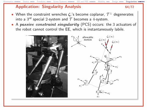
• When the constraint wrenches ζi’s become coplanar, T ⊥ degeneratesinto a 3rd special 2-system and T becomes a 4-system.
• A passive constraint singularity (PCS) occurs: the 3 actuators ofthe robot cannot control the EE, which is instantaneously labile.
Kinematics Statics Freedoms Screw Systems ISS and PSS Mobility Design Singularities
Application: Singularity Analysis 65/72
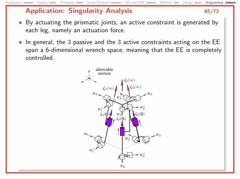
• By actuating the prismatic joints, an active constraint is generated byeach leg, namely an actuation force.
• In general, the 3 passive and the 3 active constraints acting on the EEspan a 6-dimensional wrench space, meaning that the EE is completelycontrolled.
Kinematics Statics Freedoms Screw Systems ISS and PSS Mobility Design Singularities
Application: Singularity Analysis 66/72
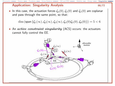
• In this case, the actuation forces ζ4(0), ζ5(0) and ζ5(0) are coplanarand pass through the same point, so that:
dim (span {ζ1(∞), ζ2(∞), ζ3(∞), ζ4(0)ζ5(0), ζ6(0)}) = 5 < 6
• An active constraint singularity (ACS) occurs: the actuatorscannot fully control the EE.
Kinematics Statics Freedoms Screw Systems ISS and PSS Mobility Design Singularities
Application: Singularity Analysis 67/72
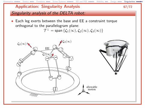
Singularity analysis of the DELTA robot:
• Each leg exerts between the base and EE a constraint torqueorthogonal to the parallelogram plane:
T ⊥ = span {ζ1(∞), ζ2(∞), ζ3(∞)}
Kinematics Statics Freedoms Screw Systems ISS and PSS Mobility Design Singularities
Application: Singularity Analysis 68/72
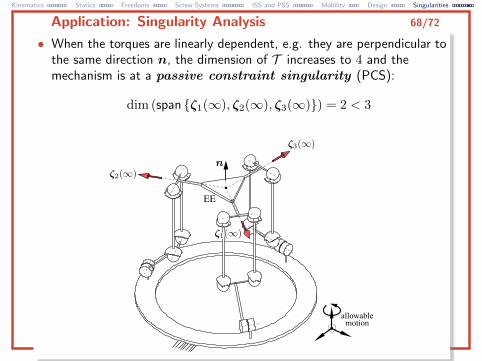
• When the torques are linearly dependent, e.g. they are perpendicular tothe same direction n, the dimension of T increases to 4 and themechanism is at a passive constraint singularity (PCS):
dim (span {ζ1(∞), ζ2(∞), ζ3(∞)}) = 2 < 3
Kinematics Statics Freedoms Screw Systems ISS and PSS Mobility Design Singularities
Application: Singularity Analysis 69/72
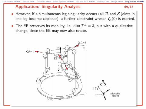
• However, if a simultaneous leg singularity occurs (all R and S joints inone leg become coplanar), a further constraint wrench ζ4(0) is exerted.
• The EE preserves its mobility, i.e. dim T ⊥ = 3, but with a qualitativechange, since the EE may now also rotate.
Kinematics Statics Freedoms Screw Systems ISS and PSS Mobility Design Singularities
Application: Singularity Analysis 70/72
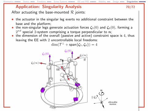
After actuating the base-mounted R joints:
• the actuator in the singular leg exerts no additional constraint between thebase and the platform;
• the non-singular legs generate actuation forces ζ5(0) and ζ6(0), forming a2nd special 2-system comprising a torque perpendicular to n;
• the dimension of the overall (passive and active) constraint space is 4, thusleaving the EE with 2 uncontrollable local freedoms:
dim(T ⊥ + span{ζ5, ζ6}) = 4
Kinematics Statics Freedoms Screw Systems ISS and PSS Mobility Design Singularities
Conclusions 71/72
• Screws are geometrical entities that represent both theinstantaneous motion of a rigid body (twist) and the set ofgeneralized forces acting upon it (wrench).
• Screw theory naturally provides the geometrical and algebraicconcepts and tools underlying the first-order kinematics andstatics of rigid bodies.
• Screw theory provides a strong geometrical insight into manycomplex physical phenomena that engineers have to deal with,such as: mobility analysis, singularities, constraint design, typesynthesis of mechanisms.
Kinematics Statics Freedoms Screw Systems ISS and PSS Mobility Design Singularities
End of presentation 72/72
Presentation by:Marco Carricato, Yuanqing Wu
GRAB—Group of Robotics, Automation and BiomechanicsUniversity of Bologna
Italy


![Singularities and exotic spheres - Numdamarchive.numdam.org/article/SB_1966-1968__10__13_0.pdf · on the topology of isolated singularities ... JANICH [9]. § 1. ... SINGUlARITIES](https://img.pdfslide.net/doc/110x75/5b14468c7f8b9a397c8c357f/singularities-and-exotic-spheres-on-the-topology-of-isolated-singularities.jpg)


![arXiv:math/0602297v1 [math.AG] 14 Feb 2006 · compute them, for example, Brieskorn singularities by A. Hefez and F. Lazzari [21], certain singularities and unimodal singularities](https://img.pdfslide.net/doc/110x75/5c01681a09d3f2fa038c99a6/arxivmath0602297v1-mathag-14-feb-2006-compute-them-for-example-brieskorn.jpg)