Embed Size (px)
Citation preview

Scrolling Marquee DisplayFinal Project ReportDecember 9, 2000
E155
Dan Smith and Katherine Wade
Abstract:
A Scrolling Marquee Display is a visually appealing way to display more information than can be fit uponthe single screen. This project will create a scrolling Marquee Display using a 2X16 LCD that willdisplay up to ten messages that scroll across the screen. The messages will be input to the FPGA, “videogame high score”- style, using a 16 button keypad. The FPGA will debounce the keypad entries and passthem to the HC11, which will control the LCD functions. Users will be able to create, delete, and edit the16-character long messages, which will then be scrolled across the LCD screen for their viewingenjoyment.

2
Introduction
We would like to make a nifty scrolling marquee that displays messages. However, most commercialscrolling marquees use lots of LEDs, which is difficult to control using the small-scale equipmentavailable in the Microprocessors laboratory. Instead, we are using an LCD display with built-in characterdisplay capabilities to serve the same purpose. The messages will still be scrolled across the display as ina regular marquee. The LCD device we are using can be easily controlled with an HC11.
Overview:
LCD HC11 FPGA
Keypad
The FPGA Polls anddebounces the keypad entry,and sends it via the serial portto the HC11The HC11 receives the keypress data from
the FPGA. It also controls the LCD displayand manages the queue of messages, whichare stored in the HC11’s memory.

3
Optrex DMC 16249 LCD
We received the Optrex DMC-16249 2x16 LCD display. Here is what it looks like:
On the LED display, 14 pins are used to display text. The first six of these, Pins 1 – 6, are the controlbits used to power the LCD and enable reading and writing. The other 8 pins, 7-14, are used to senddata to the LCD.
The HC11 will control the LCD directly. A parallel port (Port B) will be used to send the 8-bitdata to pins 7-14, and additional pins from the HC11 will be wired directly to the appropriate controlbits.
The pin holes on the LCD were filled with jumper pins and soldered to the LCD board. This waywe can put the LCD on our breadboard for ease of wiring. If the jumper pins are not desired forfuture use, they can be unsoldered and removed.
H E L L O W O R L D !X X X X X X X X X X X X X X X X
Control Data
1 14
4
Schematics
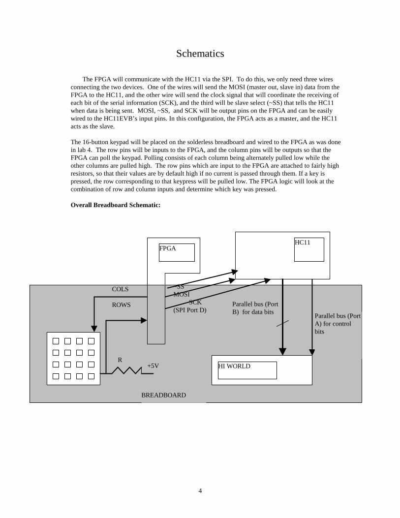
The FPGA will communicate with the HC11 via the SPI. To do this, we only need three wiresconnecting the two devices. One of the wires will send the MOSI (master out, slave in) data from theFPGA to the HC11, and the other wire will send the clock signal that will coordinate the receiving ofeach bit of the serial information (SCK), and the third will be slave select (~SS) that tells the HC11when data is being sent. MOSI, ~SS, and SCK will be output pins on the FPGA and can be easilywired to the HC11EVB’s input pins. In this configuration, the FPGA acts as a master, and the HC11acts as the slave.
The 16-button keypad will be placed on the solderless breadboard and wired to the FPGA as was donein lab 4. The row pins will be inputs to the FPGA, and the column pins will be outputs so that theFPGA can poll the keypad. Polling consists of each column being alternately pulled low while theother columns are pulled high. The row pins which are input to the FPGA are attached to fairly highresistors, so that their values are by default high if no current is passed through them. If a key ispressed, the row corresponding to that keypress will be pulled low. The FPGA logic will look at thecombination of row and column inputs and determine which key was pressed.
Overall Breadboard Schematic:
FPGAHC11
HI WORLD
Parallel bus (PortB) for data bits
~SSMOSI SCK(SPI Port D)
COLS
ROWS
R+5V
BREADBOARD
Parallel bus (PortA) for controlbits
5
Microcontroller Design
The hc11 is responsible for controlling the LCD display based on the key presseson the keypad. It receives messages serially from keypad (with the keypad as master, thehc11 as slave) using the SPI interface. These messages are received as a binary encodingof the value that was pressed on the keypad. It sends messages out to the LCD display viaparallel ports A and B.
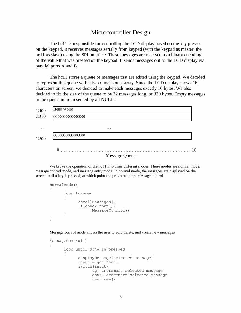
The hc11 stores a queue of messages that are edited using the keypad. We decidedto represent this queue with a two dimensional array. Since the LCD display shows 16characters on screen, we decided to make each messages exactly 16 bytes. We alsodecided to fix the size of the queue to be 32 messages long, or 320 bytes. Empty messagesin the queue are represented by all NULLs.
C000C010
… …
C200
0… … … … … … … … … … … … … … … … … … … … … … … … … … … … 16Message Queue
We broke the operation of the hc11 into three different modes. These modes are normal mode,message control mode, and message entry mode. In normal mode, the messages are displayed on thescreen until a key is pressed, at which point the program enters message control.
normalMode(){
loop forever{
scrollMessages()if(checkInput())
MessageControl()}
}
Message control mode allows the user to edit, delete, and create new messages
MessageControl(){
Loop until done is pressed{
displayMessage(selected message)input = getInput()switch(input)
up: increment selected messagedown: decrement selected messagenew: new()
Hello World
0000000000000000
0000000000000000

6
edit: edit(selected message)remove: remove(selected message)
}}
The remove() function just converts the selected message to NULLs. Thenew() function finds an empty slot in the array, converts all the characters tospaces, and then calls edit() on that position.
new(){
find empty messageconvert to spacesedit(empty message)
}
The edit() function is the third mode of operation: message entry. The edit function getskeystrokes from the user and modifies the message. It keeps a cursor position on the message and allowsthe user to change the current character, or move left or right.
edit(){
loop until done is pressed{
displayMessagewithCursor(cursor position)input = getInput()switch(input)up: increment selected message[cursor position] down: decrement selected message[cursor position]left: increment cursor positionsright: decrement cursor position
}}
7
FPGA Design
Describe the function of the hardware in your FPGA, including inputs, outputs, and major hardwaremodules. Describe the key logic, using datapath or FSM diagrams as needed. This section should givethe reader enough information to understand the Verilog code and/or FPGA schematics in the appendix.
So far we have coded modules in Verilog to take care of the polling, debouncing, and SPI communication.The code for these modules can be found in Appendix A.
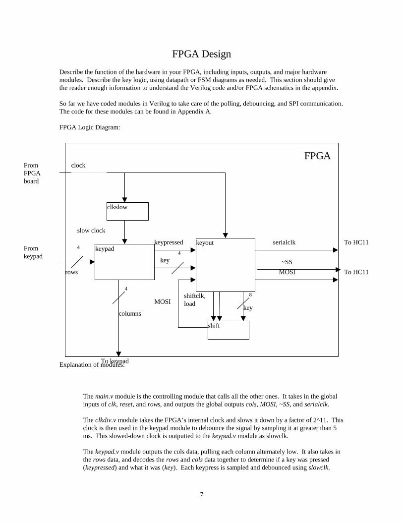
FPGA Logic Diagram:
Explanation of modules:
The main.v module is the controlling module that calls all the other ones. It takes in the globalinputs of clk, reset, and rows, and outputs the global outputs cols, MOSI, ~SS, and serialclk.
The clkdiv.v module takes the FPGA’s internal clock and slows it down by a factor of 2^11. Thisclock is then used in the keypad module to debounce the signal by sampling it at greater than 5ms. This slowed-down clock is outputted to the keypad.v module as slowclk.
The keypad.v module outputs the cols data, pulling each column alternately low. It also takes inthe rows data, and decodes the rows and cols data together to determine if a key was pressed(keypressed) and what it was (key). Each keypress is sampled and debounced using slowclk.
To keypad
clkslow
keypadkeyout
shift
clock
slow clock
keypressed
MOSIshiftclk,load
MOSI
serialclk
key4
key
8
rows
4
columns
4
FPGAFromFPGAboard
Fromkeypad
To HC11
To HC11~SS

8
The shift.v module is a 8-bit shift register which takes in a clk, load, and indata, and outputsMOSI. When load is enabled, the indata is loaded directly into the shift register in parallel. Theclk then shifts the data through the registers. The MSB is outputted as outdata.
The keyout.v module takes in clk, reset, keypressed, key, and outputs MOSI, ~SS, and serialclk.It stores key in shift.v and then generates clocks for the serial output and the shift register. Theshift register clock is the opposite of the serial output clock, delayed by one clock cycle. Theserialclk, ~SS, and the MOSI are outputted to the FPGA in SPI format.

9
Results
We were able to complete our project as proposed. The marquee could store up to 32 messages,with each message being 16 characters long. The marquee could scroll the messages, and supported theadd, delete, edit, and new message operations described above. The edit message mode supported thecharacter ‘a-z’, “A-Z’, and some special characters like ‘ ‘, “#’, ‘!’, etc. Scrolling through all thesecharacters to find the one you wanted was a little cumbersome. It was suggested to us that instead of usingone keypad and entering in messages video game style, we could instead use two keypads and enter in theletters “A-Z’ directly (26 buttons for ‘A-Z’, 6 control buttons).
One of the difficult parts of the project was trying to get the FPGA to communicate serially withthe HC11 using the FPGA as a master. The Verilog code to send data using this technique ended up beingmore difficult than we thought. However, we were able to get it working.
We were unable to write the code in C as we hoped, because we did not get the C compilerworking in time. However, after we had written the code in assembly, we did get the C compiler to work.We were unable to use the compiler for our project because we had already written the assembly code,however, we hope that students will be able to use what we’ve learned about the compiler for futureprojects.

10
References
Check the following links for up-to-date information about LCDs.
[1] Fil’s FAQ Link-In Corner: LCD Program and Pinout FAQ,http://www.repairfaq.org/filipg/LINK/F_LCD_progr.html[2] Optrex DMC-16249 Documentation, http://www.optrex.com/pdfs/Dmcman_full.pdf
Parts List
List all of the components you used other than standard resistors, capacitors, and parts available in theMicroP’s lab.
Part Source Vendor Part # PriceOptrex DMC 162492x 16 LCD
MicroPs lab
16-button keypad MicroPs lab

11
Appendix A: Pinouts

12
Serial Interface:
FPGA HC11MOSI 45 PD3SCK 46 PD4~SS 47 PD5
LCD Interface:
LCD HC11 OTHERVss GNDVcc VccVee GNDRS PA4R/W PA5E PA3DB0 PB0DB1 PB1DB2 PB2DB3 PB3DB4 PB4DB5 PB5DB6 PB6DB7 PB7
Keyboard Interface:Keyboard FPGARow0 P38Row1 P39Row2 P40Row3 P44Col0 P18Col1 P19Col2 P20Col3 P23

13
Appendix B: Report on GCC Compiler
14
Report on gcc
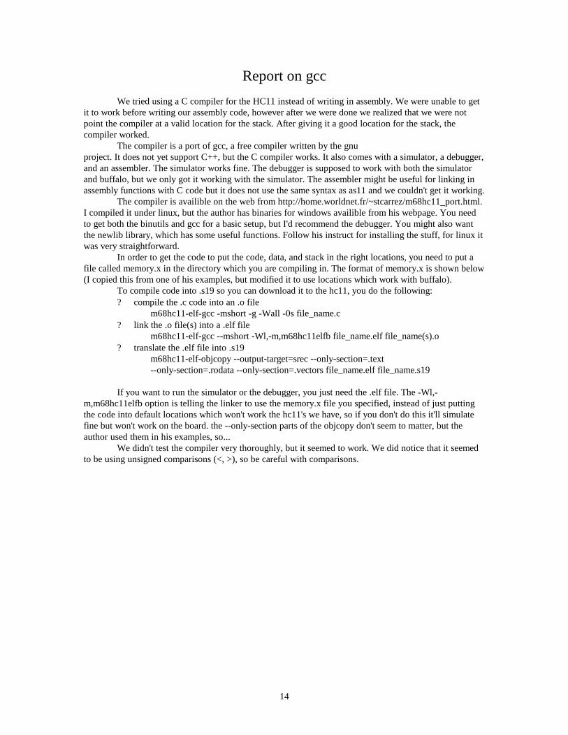
We tried using a C compiler for the HC11 instead of writing in assembly. We were unable to getit to work before writing our assembly code, however after we were done we realized that we were notpoint the compiler at a valid location for the stack. After giving it a good location for the stack, thecompiler worked.
The compiler is a port of gcc, a free compiler written by the gnuproject. It does not yet support C++, but the C compiler works. It also comes with a simulator, a debugger,and an assembler. The simulator works fine. The debugger is supposed to work with both the simulatorand buffalo, but we only got it working with the simulator. The assembler might be useful for linking inassembly functions with C code but it does not use the same syntax as as11 and we couldn't get it working.
The compiler is availible on the web from http://home.worldnet.fr/~stcarrez/m68hc11_port.html.I compiled it under linux, but the author has binaries for windows availible from his webpage. You needto get both the binutils and gcc for a basic setup, but I'd recommend the debugger. You might also wantthe newlib library, which has some useful functions. Follow his instruct for installing the stuff, for linux itwas very straightforward.
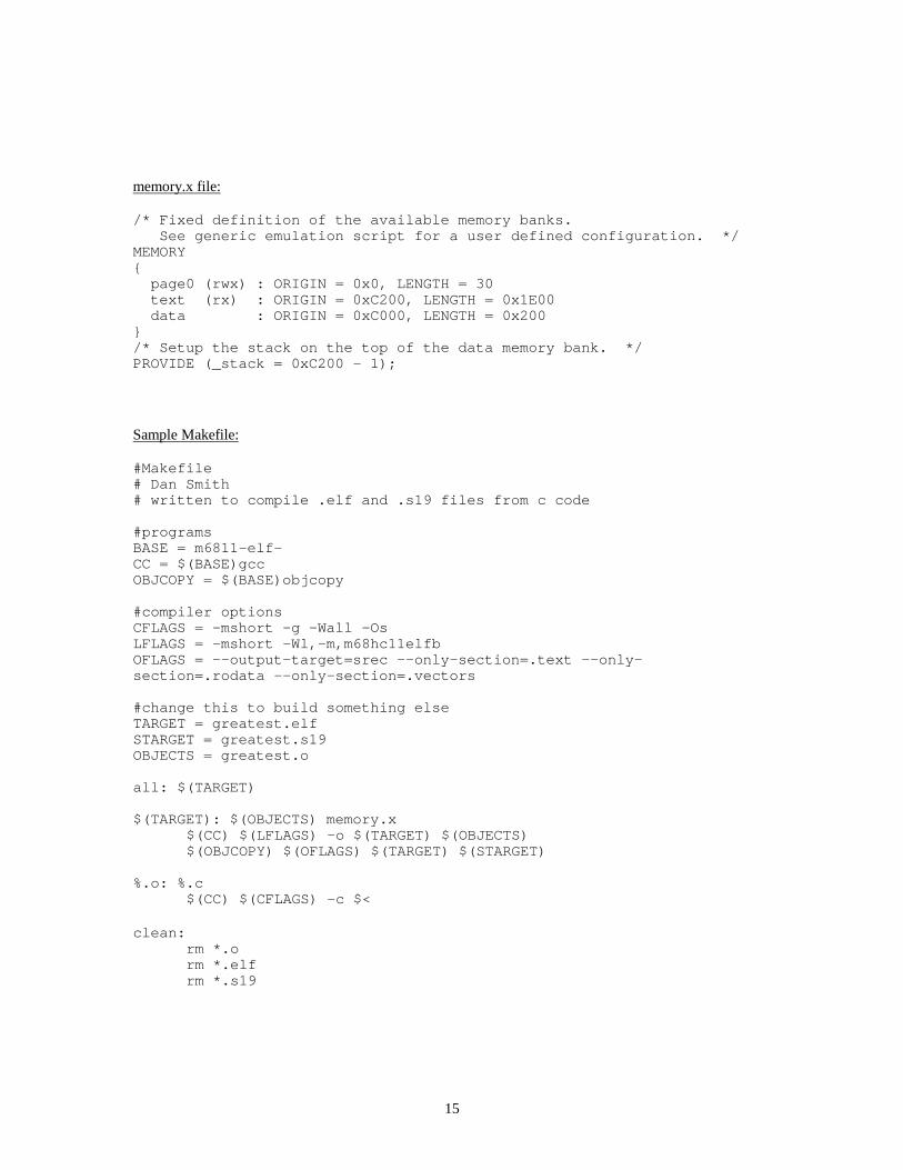
In order to get the code to put the code, data, and stack in the right locations, you need to put afile called memory.x in the directory which you are compiling in. The format of memory.x is shown below(I copied this from one of his examples, but modified it to use locations which work with buffalo).
To compile code into .s19 so you can download it to the hc11, you do the following:? compile the .c code into an .o file
m68hc11-elf-gcc -mshort -g -Wall -0s file_name.c? link the .o file(s) into a .elf file
m68hc11-elf-gcc --mshort -Wl,-m,m68hc11elfb file_name.elf file_name(s).o? translate the .elf file into .s19
m68hc11-elf-objcopy --output-target=srec --only-section=.text--only-section=.rodata --only-section=.vectors file_name.elf file_name.s19
If you want to run the simulator or the debugger, you just need the .elf file. The -Wl,-m,m68hc11elfb option is telling the linker to use the memory.x file you specified, instead of just puttingthe code into default locations which won't work the hc11's we have, so if you don't do this it'll simulatefine but won't work on the board. the --only-section parts of the objcopy don't seem to matter, but theauthor used them in his examples, so...
We didn't test the compiler very thoroughly, but it seemed to work. We did notice that it seemedto be using unsigned comparisons (<, >), so be careful with comparisons.
15
memory.x file:
/* Fixed definition of the available memory banks. See generic emulation script for a user defined configuration. */MEMORY{ page0 (rwx) : ORIGIN = 0x0, LENGTH = 30 text (rx) : ORIGIN = 0xC200, LENGTH = 0x1E00 data : ORIGIN = 0xC000, LENGTH = 0x200}/* Setup the stack on the top of the data memory bank. */PROVIDE (_stack = 0xC200 - 1);
Sample Makefile:
#Makefile# Dan Smith# written to compile .elf and .s19 files from c code
#programsBASE = m6811-elf-CC = $(BASE)gccOBJCOPY = $(BASE)objcopy
#compiler optionsCFLAGS = -mshort -g -Wall -OsLFLAGS = -mshort -Wl,-m,m68hc11elfbOFLAGS = --output-target=srec --only-section=.text --only-section=.rodata --only-section=.vectors
#change this to build something elseTARGET = greatest.elfSTARGET = greatest.s19OBJECTS = greatest.o
all: $(TARGET)
$(TARGET): $(OBJECTS) memory.x$(CC) $(LFLAGS) -o $(TARGET) $(OBJECTS)$(OBJCOPY) $(OFLAGS) $(TARGET) $(STARGET)
%.o: %.c$(CC) $(CFLAGS) -c $<
clean:rm *.orm *.elfrm *.s19

16
Appendix C: Verilog Files

17
module main (clk, reset, rows, cols, mosi, serialclk, slaveselect) ;
input clk; //FPGA internal clockinput reset; //FPGA internal reset (big red button)
input [3:0] rows;output [3:0] cols;
output mosi; //the keypress bits for serial outputoutput serialclk; //the clock used to control the serial transferoutput slaveselect; //goes low during the transmission, high otherwise
wire slowclk; //the slowed-down FPGA clockwire[3:0] key; //the key that was pressed
clkdiv myclkdiv(clk, reset, slowclk); //slow down the clockkeypad mykeypad(slowclk, reset, rows, cols, key, keypressed); //poll the keypadkeyout mykeyout(clk, reset, key, keypressed, mosi, serialclk, slaveselect);
//output the pressed key serially
endmodule
///////////////////////////////////////module clkdiv(clk, reset, slowclk);
input clk; //FPGA internal clockinput reset; //FPGA internal reset (big red button)output slowclk; //the slowed-down FPGA clock
reg[11:0] count;
//This synthesizes to an asynchronously resettable counter.//The reset line is tied to the global set/reset line of the FPGAalways@(posedge clk or posedge reset)
if (reset) count = 0;else count = count +1;
assign slowclk = count[11];
endmodule
///////////////////////////////////////////////////////module keypad(slowclk, reset, rows, cols, key, keypressed);
input slowclk; //slowed-down clockinput reset; //FPGA internal reset (big red button)
input [3:0] rows;output [3:0] cols;
output [3:0] key; //contains the binary value of the pressed keyoutput keypressed; //a key was pressed
reg keypressed; //for FSMreg [3:0] cols;reg [3:0] key;
//scanning FSMalways @(posedge slowclk or posedge reset)
if (reset) beginkeypressed <=0;cols <= 4'b0111;
end else if (&rows) begin//no key pressed on this column, so keep scanningkeypressed <= 0;cols <= {cols[0], cols [3:1]}; //shift cols right
end else if (~keypressed) beginkeypressed <= 1;
end//otherwise wait until all keys are released before continuing
//keypad conversionalways@(rows or cols)

18
case ({rows, cols})8'b0111_0111: key <= 'hC;8'b1011_0111: key <= 'hD;8'b1101_0111: key <= 'hE;8'b1110_0111: key <= 'hF;8'b0111_1011: key <= 'h3;8'b1011_1011: key <= 'h6;8'b1101_1011: key <= 'h9;8'b1110_1011: key <= 'hB;8'b0111_1101: key <= 'h2;8'b1011_1101: key <= 'h5;8'b1101_1101: key <= 'h8;8'b1110_1101: key <= 'h0;8'b0111_1110: key <= 'h1;8'b1011_1110: key <= 'h4;8'b1101_1110: key <= 'h7;8'b1110_1110: key <= 'hA;default: key <= 'h0;
endcase
endmodule
/////////////////////////////////////////////module shift (clk, reset, load, indata, outdata) ;
//this is a basic 8-bit shift register
input clk, reset ;input load;input [7:0] indata ;output outdata ;
reg [7:0] data;
always @(posedge clk or posedge reset)begin if(reset == 1)
data <= 8'b1010_1010; else if (load == 1) data <= indata; //if loading, immediately load everything in
elsebegin //otherwise, shift everything through
data[7] <= data[6]; data[6] <= data[5]; data[5] <= data[4]; data[4] <= data[3]; data[3] <= data[2]; data[2] <= data[1]; data[1] <= data[0]; data[0] <= 1;
endend
assign outdata = data[7]; //the 7th bit is the MOSI out.
endmodule
///////////////////////////////////////////////////////////////////////module keyout (clk, reset, key, keypressed, mosi, serialclk, slaveselect) ;
input clk, reset; //serial clockinput [3:0] key; //the key that was pressedinput keypressed;
output mosi; //the keypress bits for serial outputoutput serialclk; //clock that controls the serial transferoutput slaveselect; //low during transmission, high otherwise.
reg [7:0] shiftreg; //shift register that holds the serial outputreg [3:0] bitcounter;
reg shiftclk;reg serialclk;reg previouslynotpressed;reg load;
19
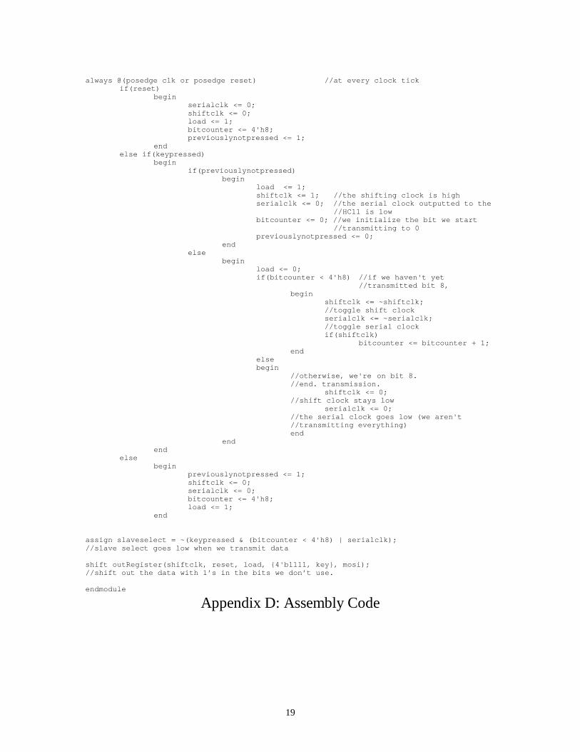
always @(posedge clk or posedge reset) //at every clock tickif(reset)
beginserialclk <= 0;shiftclk <= 0;load <= 1;bitcounter <= 4'h8;previouslynotpressed <= 1;
endelse if(keypressed)
beginif(previouslynotpressed)
beginload <= 1;shiftclk <= 1; //the shifting clock is high serialclk <= 0; //the serial clock outputted to the
//HC11 is lowbitcounter <= 0; //we initialize the bit we start
//transmitting to 0previouslynotpressed <= 0;
endelse
beginload <= 0;if(bitcounter < 4'h8) //if we haven't yet
//transmitted bit 8,begin
shiftclk <= ~shiftclk;//toggle shift clockserialclk <= ~serialclk;//toggle serial clockif(shiftclk)
bitcounter <= bitcounter + 1;end
elsebegin
//otherwise, we're on bit 8.//end. transmission.
shiftclk <= 0;//shift clock stays low
serialclk <= 0;//the serial clock goes low (we aren't//transmitting everything)end
endend
elsebegin
previouslynotpressed <= 1;shiftclk <= 0;serialclk <= 0;bitcounter <= 4'h8;load <= 1;
end
assign slaveselect = ~(keypressed & (bitcounter < 4'h8) | serialclk);//slave select goes low when we transmit data
shift outRegister(shiftclk, reset, load, {4'b1111, key}, mosi);//shift out the data with 1’s in the bits we don’t use.
endmodule
Appendix D: Assembly Code

20
queue.asm************************************************************** Dan Smith* 11/28/00* e155 final project* main event loop* description - this program maintains a queue of messages* it allows editing of the messages. It displays the messages* to an lcd display and receives the messages from an FPGA. This* file contains the message control aspects.
*************************************************************constants
*locations, sizesQUEUE_LOC EQU $C000QUEUE_END EQU $C200MESSAGE_SIZE EQU $10NG_MESS_SIZE EQU $fff0NUM_MESSAGES EQU $1fSTACK_LOC EQU $C380PROGRAM_LOC EQU $C400SCRATCH_LOC EQU $C390 ;used for scratch space in memory
*keysUP EQU $FDDOWN EQU $F6LEFT EQU $F3RIGHT EQU $F9NEXT EQU $F5PREV EQU $F2DONE EQU $F8DELETE EQU $F7ADD EQU $F4EDIT EQU $F1
*chactactersSPACE EQU ' 'NULL EQU #0FIRST_CHAR EQU ' 'LAST_CHAR EQU 'z'
************************************************************** initial queue
org QUEUE_LOCfcc "Marquee "fcc "Display "fcc "Katherine "fcc " &Dan"fcc "E155 is fun&EZ!!"
PREDEF: fcc "\0\0\0\0\0\0\0\0\0\0\0\0\0\0\0\0"
************************************************************** initialization code* clear the queue, initialize the i/o devices
org PROGRAM_LOC

21
lds #STACK_LOCjsr INITSPI ;initialize the serial interfacejsr INITDR ;initialize the displayjsr CLEAR ;clear the displayjsr CLEAR_QUEUE ;clear the queueldx #QUEUE_LOC ;load the X register with a pointer to
queue
*************************************************************main loop* scroll through messages, on a keypress go the the next messageMAIN:
pshx ;push x onto the queue for subroutine callsjsr DISPLAY_MESSAGEjsr WAITASECpulxinx ;shift the display by 1 (scrolling)clracmpa 0,X ;check to see if the next value is nullbne CONT1 ;if the next value is not null go onldx #QUEUE_LOC ;go back to the beginning of the queue
CONT1: pshxjsr TESTDATA ;after this, A will be 0 if no inputpulxcmpa #$0beq MAIN ;if there is no input, display againpshxjsr MESSAGE_CONTROL ;otherwisepulxbra MAIN
*******************************main loop helper functions
*clear the queueCLEAR_QUEUE:
ldy #PREDEF ;start the end of the predefined messagesldab #NULL ;write null to the queue
LOOP4: stab 0,Yinycpy #QUEUE_ENDbne LOOP4
rts
*************************************************************message control loop*create, delete, edit messages*sequence* display the current message* read input (wait for it)* switch(input)* create a new message* delete current message* edit the current message* go to the next message* go to the previous message* return to main loop

22
MESSAGE_CONTROL:ldx #QUEUE_LOC ;start at the beginning of the queue
LOOP1: pshxjsr DISPLAY_MESSAGE ;display the messagejsr GETDATA ;wait for inputpulx
cmpa #NEXT ;go to the next messagebne CASEA1jsr NEXT_MESSAGEbra LOOP1
CASEA1: cmpa #PREV ;go to the previous messagebne CASEA2jsr PREV_MESSAGEbra LOOP1
CASEA2: cmpa #DELETE ;delete a messagebne CASEA3jsr DELETE_MESSAGEbra LOOP1
CASEA3: cmpa #EDIT ;edit a messagebne CASEA4jsr EDIT_MESSAGEbra LOOP1
CASEA4: cmpa #ADD ;add a messagebne CASEA5jsr NEW_MESSAGEbra LOOP1
CASEA5: cmpa #DONE ;return to main loopbne CASEA6rtsbra LOOP1
CASEA6: bra LOOP1 ;default case
*******************************message control helper functions
*go to the next message* X = messageNEXT_MESSAGE:
ldab #MESSAGE_SIZEabxclra ;check to see if we have reached the endcmpa 0,Xbne CONT2ldx #QUEUE_LOC ;if we have, go to the beginning
CONT2: rts
*go to the previous message* X = messagePREV_MESSAGE:
cpx #QUEUE_LOC ;check to see if we have reached thebeginning
bne CONT3

23
rts ;if we have, don't go anywhereCONT3:
xgdx ;go back a messageaddd #NG_MESS_SIZE ;xgdx ;rts
*message creationNEW_MESSAGE:
jsr FIND_TAIL ;find the end of the queuecmpa #$0 ;see if the queue is fullbne CONT4 ;if the queue is not full, branchpshx ;display an errorjsr ERRORpulxrts
CONT4: pshx ;set message might corrupt Xldaa #SPACEjsr SET_MESSAGE ;set the message to spacespulxjsr EDIT_MESSAGE ;edit the newly created messagerts
*message deletion* X = messageDELETE_MESSAGE:
pshxjsr MOVE_TAIL ;move the last nonempty message to
* ;the deleted locationspulxjsr FIND_TAIL ;find the tailcpx #QUEUE_LOC ;if the queue is empty returnbeq CONT12 ;
xgdx ;addd #NG_MESS_SIZE ;find the last nonempty messagexgdx ;ldaa #NULLpshxjsr SET_MESSAGE ;set the last message to NULLpulx
CONT12: rts
*find the tail of the queue (the first empty message*if the queue is full, store 0 in accumulator A*otherwise store 1*tail is stored in X*return in AFIND_TAIL:
ldx #QUEUE_LOC ;start a message below the queuexgdxaddd #NG_MESS_SIZExgdxldaa #NULL ;we want to check for NULL
* ;at each messageLOOP2: ldab #MESSAGE_SIZE ;increment the pointer

24
abx* note, we want to check to see if we are at the last message* the reason is because we cant to leave the last message all NULLs
cpx #QUEUE_ENDbne CONT5ldaa #0 ;if the queue is full return 0rts
CONT5: cmpa 0,Xbne LOOP2 ;if this isn't the end of the queue, go *
;on
ldaa #1 ;return 1rts
*move last message in queue to a location pointed to by the X indexregister*used for delete.* X = messageMOVE_TAIL:
pshxjsr FIND_TAILpuly ;getting tricky, we want Y to have the old
* ;location and X to have the tail of the listcpx #QUEUE_LOC ;check to see if tail = head (empty queue)beq CONT6 ;if they're equal just return
xgdx ;addd #NG_MESS_SIZE ;xgdx ;go to the last nonempty messagesty SCRATCH_LOC ;compare y to xcpx SCRATCH_LOC ;beq CONT6 ;if they're equal, just return
ldab #MESSAGE_SIZE ;initialize counterLOOP6: ldaa 0,X ;get a byte from the tail
staa 0,Y ;put it in the locationinx ;iny ;go to the next bytedecb ;decrement counterbne LOOP6 ;loop
CONT6: rts
*************************************************************message editing*this function assumes the X index register is already pointing*at the message in memory. It just diplays the cursor and changes*the characters* sequence* display message* display cursor* get input* switch (input)* move cursor left* move cursor right* increment character* decrement character* return to message control

25
* X = message
EDIT_MESSAGE:stx SCRATCH_LOC ;ldy SCRATCH_LOC ;copy X to Ypshypshxjsr DISPLAY_MESSAGE ;display the messagejsr HOMEjsr CUR_ON ;turn on the cursorpulxpuly
LOOP7: pshypshxjsr GETDATA ;wait for inputpulxpuly
cmpa #UP ;go up a characterbne CASEB1jsr UP_CHARbra LOOP7
CASEB1: cmpa #DOWN ;go down a characterbne CASEB2jsr DOWN_CHARbra LOOP7
CASEB2: cmpa #LEFT ;go leftbne CASEB3jsr PREV_CHARbra LOOP7
CASEB3: cmpa #RIGHT ;go rightbne CASEB4jsr NEXT_CHARbra LOOP7
CASEB4: cmpa #DONE ;return to message control loopbne CASEB5pshxjsr CUR_OFFpulxrtsbra LOOP7
CASEB5: bra LOOP7 ;default case
rts
*******************************edit message helper functions
*rotate character pointed at by Y up*Y = charUP_CHAR:
inc 0,Y ;go up a characterldaa 0,Y ;deca ;

26
cmpa #LAST_CHAR ;check to see if we're at the last characterbne CONT8ldaa #FIRST_CHAR ;staa 0,Y ; jump to the first character
CONT8: ldaa 0,Y ; write the character to the LCDpshxpshyjsr WRITEDjsr CUR_LEFTpulypulxrts
*rotate character down*Y = charDOWN_CHAR
dec 0,Y ;go down a characterldaa 0,Y ;inca ;cmpa #FIRST_CHAR ;check to see if we're before the first charbne CONT9ldaa #LAST_CHAR ;staa 0,Y ;jump to the last character
CONT9: ldaa 0,Y ;write the character to the LCDpshxpshyjsr WRITEDjsr CUR_LEFTpulypulxrts
*go to the next character (in memory and display)*Y = char* X = start of messageNEXT_CHAR:
pshx ;save for laterldab #MESSAGE_SIZEdecbabx ;X now holds the end of the messagestx SCRATCH_LOC ;pulxcpy SCRATCH_LOC ;check to see if Y is the end of the messagebne CONT10stx SCRATCH_LOCldy SCRATCH_LOC ;go the the beginning of the messagepshxpshyjsr HOME ;move the cursor homepulypulxrts
CONT10: iny ;increment the pointerpshxpshyjsr CUR_RIGHT ;move the cursor left

27
pulypulxrts
*go to the previous character (in memory and display)*Y = char*X = start of messagePREV_CHAR:
stx SCRATCH_LOC ;cpy SCRATCH_LOC ;check to see if Y is the start of the messagebne CONT11rts ;just stay at beginning if at beginning, no
wrap* ;around
CONT11: dey ;decrement the pointerpshxpshyjsr CUR_LEFT ;move the cursor rightpulypulxrts
*************************************************************generic helper functions
*display a message* X = pointer to messageDISPLAY_MESSAGE:
ldab #MESSAGE_SIZE ;initialize counterincbpshxpshbjsr HOME ;go to the beginning of the displaypulbpulx
LOOP3:ldaa 0,Xpshxpshbjsr WRITEDpulbpulxinx ;increment the pointerdecb ;decrement the counterbne LOOP3 ;loop until counter=0rts
*set a message to the value accumulator A*used to clear a message or initizialize it to some character* A = value to set* X = pointer to messageSET_MESSAGE:
ldab #MESSAGE_SIZE ;b is a counterLOOP5: staa 0,X
inxdecbbne LOOP5
rts

28
*display an error message
ERRM FCC "ERROR " ;the acual error messageERROR: ldx #ERRM ;
jsr DISPLAY_MESSAGE ;display the string abovejsr WAITASEC ; delay for 1 secondjsr WAITASECjsr WAITASECldx QUEUE_LOC ;reinitialize Xrts
*wait one-third of a secondWAITASEC: ldab #10 ; 10 overflowsDELAY1: ldaa #10000000 ; clear the TOF to start the delay
staa $1025 ; store in TFLG2SPIN1: tst $1025 ; do 10 overflows for approx. 1/3 sec
bpl SPIN1 ; is flag 0? branch on bit 7 is cleardecb ; decrement counterbne DELAY1 ; if we haven't counted to 0 yet, delay againrts

29
interface.asm*LCD Assembly Subroutines*Katherine Wade*11/30/00*******************************this code is based upon Jason Fong and Ferndando Mattos' code from lastyear.***********************
PORTA EQU $1000 *LCD Control RegisterPORTB EQU $1004 *LCD Data Register
DDRD EQU $1009 *SPI Configuration RegisterSPCR EQU $1028 *SPI Control RegisterSPSR EQU $1029 *SPI Status RegisterSPDR EQU $102A *SPI Data Register
ZERO EQU $0000 *for comparison purposesDELAY EQU $0002 *holds the amount to wait
*************************************this org is commented out so that this code will be put following*the queue code in memory by the assembler* ORG $c000
**************************************************************initialize the serial port as a slaveINITSPI: ldaa #%00000100 staa DDRD ldaa #%01001100 staa SPCR clra rts
****************************************************INITDR: ldaa #$38 //initializes the LCD driver jsr WRITEC ldaa #$38 jsr WRITEC ldaa #$38 jsr WRITEC ldaa #$06 jsr WRITEC ldaa #$0C jsr WRITEC rts
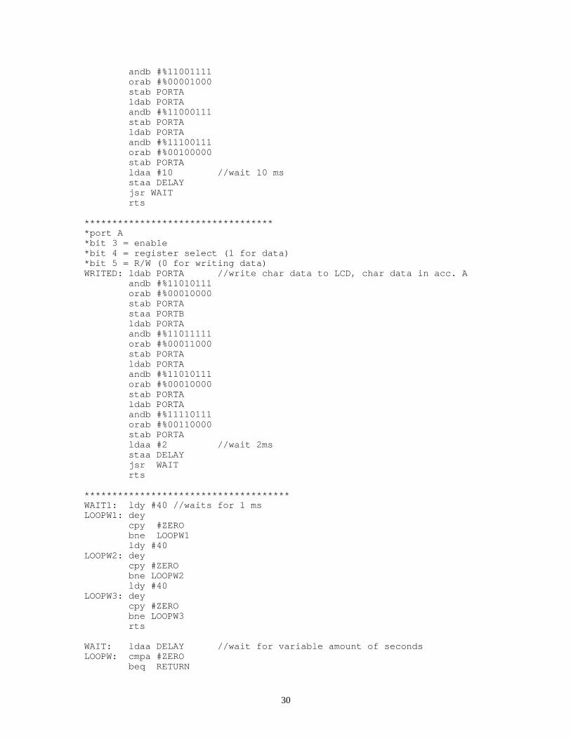
*********************************port A*bit 3 = enable*bit 4 = register select (0 for control)*bit 5 = R/W (0 for writing data)WRITEC: ldab PORTA //writes to the LCD control, control data inacc.A andb #%11000111 stab PORTA staa PORTB ldab PORTA
30
andb #%11001111 orab #%00001000 stab PORTA ldab PORTA andb #%11000111 stab PORTA ldab PORTA andb #%11100111 orab #%00100000 stab PORTA ldaa #10 //wait 10 ms staa DELAY jsr WAIT rts
***********************************port A*bit 3 = enable*bit 4 = register select (1 for data)*bit 5 = R/W (0 for writing data)WRITED: ldab PORTA //write char data to LCD, char data in acc. A andb #%11010111 orab #%00010000 stab PORTA staa PORTB ldab PORTA andb #%11011111 orab #%00011000 stab PORTA ldab PORTA andb #%11010111 orab #%00010000 stab PORTA ldab PORTA andb #%11110111 orab #%00110000 stab PORTA ldaa #2 //wait 2ms staa DELAY jsr WAIT rts
*************************************WAIT1: ldy #40 //waits for 1 msLOOPW1: dey cpy #ZERO bne LOOPW1 ldy #40LOOPW2: dey cpy #ZERO bne LOOPW2 ldy #40LOOPW3: dey cpy #ZERO bne LOOPW3 rts
WAIT: ldaa DELAY //wait for variable amount of secondsLOOPW: cmpa #ZERO beq RETURN

31
jsr WAIT1 deca jmp LOOPWRETURN: RTS
SWI
*********************************CLEAR: ldaa #$01 //clears the LCD jsr WRITEC rts
**********************************CUR_ON: ldaa #$0D //turns cursor on jsr WRITEC rts
********************************CUR_OFF: ldaa #$0C //turns cursor off jsr WRITEC rts
************************************CUR_LEFT: ldaa #$10 //moves cursor left jsr WRITEC rts
********************************CUR_RIGHT: ldaa #$14 //move cursor right jsr WRITEC rts
***************************************HOME: ldaa #$02 //move cursor home jsr WRITEC rts
************************************************wait for data from the serial portCHECKDATA: ldaa SPSR anda #%10000000 cmpa #$80 bne CHECKDATA rts
************************************************check for data from the serial port*regA = 0 if no data*regA = 0x80 if dataTESTDATA:
ldaa SPSRanda #%10000000rts
****************************************wait for data from the serial port*put in it register A

32
GETDATA: jsr CHECKDATA ldaa SPDR rts