Embed Size (px)
Citation preview
Part No. 900-287 Rev. D April 2004
SCSxx05/SCSxx20 Secure Console Server
User Guide
Models SCS3205, SCS4805, SCS820, SCS1620 with Firmware v4.3 and later

i
Copyright & Trademark © 2003, Lantronix. All rights reserved. No part of the contents of this book may be transmitted or reproduced in any form or by any means without the written permission of Lantronix. Printed in the United States of America.
Lightwave Communications is a Lantronix Inc. Company. Ethernet is a trademark of XEROX Corporation. UNIX is a registered trademark of The Open Group. Windows 95, Windows 98, Windows 2000, and Windows NT are trademarks of Microsoft Corporation. Netscape is a trademark of Netscape Communications Corporation.
LINUX GPL Compliance Certain portions of source code for the software supporting the SCSxx05™ and SCSxx20™ are licensed under the GNU General Public License (GPL) as published by the Free Software Foundation and may be redistributed and modified under the terms of the GNU GPL. A machine readable copy of the corresponding portions of GPL licensed source code are available at the cost of distribution.
Such source code is distributed WITHOUT ANY WARRANTY, INCLUDING ANY IMPLIED WARRANTY OF MERCHANTABILITY OR FITNESS FOR A PARTICULAR PURPOSE. See the GNU General Public License for more details.
A copy of the GNU General Public License is available on the Lantronix Web Site at http://www.lantronix.com/ or by visiting http://www.gnu.org/copyleft/gpl.html You can also obtain it by writing to the Free Software Foundation, Inc. 59 Temple Place, Suite 330, Boston, MA 02111-1307 USA.
Contacts Lantronix Corporate Headquarters 15353 Barranca Parkway Irvine, CA 92618, USA Phone: 949-453-3990 Fax: 949-453-3995
Technical Support Phone: 800-422-7044 or 949-453-7198 Fax: 949-450-7226 Fax: 949-450-7226 Online: www.lantronix.com/support Email: [email protected] Sales Offices For a current list of our domestic and international sales offices, go to the Lantronix web site at http://www.lantronix.com/about/contact/index.html
ii
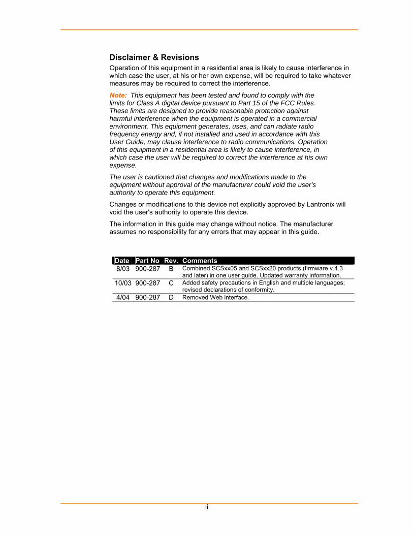
Disclaimer & Revisions Operation of this equipment in a residential area is likely to cause interference in which case the user, at his or her own expense, will be required to take whatever measures may be required to correct the interference.
Note: This equipment has been tested and found to comply with the limits for Class A digital device pursuant to Part 15 of the FCC Rules. These limits are designed to provide reasonable protection against harmful interference when the equipment is operated in a commercial environment. This equipment generates, uses, and can radiate radio frequency energy and, if not installed and used in accordance with this User Guide, may clause interference to radio communications. Operation of this equipment in a residential area is likely to cause interference, in which case the user will be required to correct the interference at his own expense.
The user is cautioned that changes and modifications made to the equipment without approval of the manufacturer could void the user’s authority to operate this equipment.
Changes or modifications to this device not explicitly approved by Lantronix will void the user's authority to operate this device.
The information in this guide may change without notice. The manufacturer assumes no responsibility for any errors that may appear in this guide.
Date Part No Rev. Comments 8/03 900-287 B Combined SCSxx05 and SCSxx20 products (firmware v.4.3
and later) in one user guide. Updated warranty information. 10/03 900-287 C Added safety precautions in English and multiple languages;
revised declarations of conformity. 4/04 900-287 D Removed Web interface.

iii
Safety Precautions
Please follow the safety precautions described below when installing and operating the SCSxx05/SCSxx20 Secure Console Server.
Cover
Do not remove the cover of the chassis. There are no user-serviceable parts inside. Opening or removing the cover may expose you to dangerous voltage that could cause fire or electric shock.
Refer all servicing to Lantronix. Service personnel: Dispose of used batteries according to the
instructions. There is a risk of explosion if the battery is replaced with an incorrect type.
Power Plug
When disconnecting the power cable from the socket, pull on the plug, not the cord.
Always connect the power cord to a properly wired and grounded power source. Do not use adapter plugs or remove the grounding prong from the cord.
Only use a power cord with a voltage and current rating greater than the voltage and current rating marked on the unit.
Install the unit near an AC outlet that is easily accessible. Always connect any equipment used with the product to properly wired
and grounded power sources. To help protect the product from sudden, transient increases and
decreases in electrical power, use a surge suppressor, line conditioner, or uninterruptible power supply (UPS).
Do not connect or disconnect this product during an electrical storm. Grounding
Maintain reliable grounding of this product. Pay particular attention to supply connections when connecting to power
strips, rather than directly to the branch circuit. Fuses
For protection against fire, replace the power-input-module fuse with the same type and rating.
Rack
Do not install the unit in a rack in such a way that a hazardous stability condition results because of uneven loading. A drop or fall could cause injury.
Before operating the SCS, make sure the SCS is secured to the rack. Port Connections
Only connect the network port to an Ethernet network that supports 10Base-T/100Base-TX.
Only connect device ports to equipment with serial ports that support EIA-232 (formerly RS-232C).
Only connect the terminal port to equipment with serial ports that support EIA-232 (formerly RS-232C).
iv
Precauciones de seguridad Al instalar y utilizar el servidor seguro de consola SCSxx05/SCSxx20, observe las precauciones de seguridad que se describen a continuación.
Tapa
No retire la tapa del chasis. En el interior no hay ninguna pieza que el usuario deba manipular. Abrir o retirar la tapa puede exponer al usuario a tensiones peligrosas que pueden causar fuego o electrocución. Si la batería se sustituye por una de tipo incorrecto, puede producirse una explosión.
Confíe todas las actividades de mantenimiento o reparación a Lantronix. Personal de mantenimiento: Deshágase de las baterías usadas de
acuerdo con las instrucciones. Si la batería se sustituye por una de tipo incorrecto, puede producirse una explosión.
Enchufe de alimentación
Al desconectar el cable de alimentación de la toma, tire del enchufe, no del propio cable.
Conecte siempre el cable de alimentación a una toma eléctrica correctamente cableada y conectada a tierra. No use adaptadores de enchufes ni elimine la patilla de toma de tierra del cable.
Use sólo un cable de alimentación adecuado para unos valores de tensión e intensidad superiores a la tensión y la intensidad indicados en la unidad.
Instale la unidad cerca de un toma de CA de fácil acceso. Conecte siempre cualquier equipo que se use con el producto a tomas
eléctricas correctamente cableadas y conectadas a tierra. Para proteger el producto contra aumentos y descensos transitorios
bruscos de la alimentación eléctrica, use un supresor de sobrecargas momentáneas, un acondicionador de línea, o una fuente de alimentación ininterrumpida (UPS).
No conecte ni desconecte este producto durante una tormenta eléctrica. Toma de tierra
Mantenga este producto conectado en todo momento a una toma de tierra fiable.
Preste especial atención a las conexiones de alimentación cuando se conecta a regletas de terminales, en lugar de hacerlo directamente al circuito derivado.
Fusibles
Para proteger la unidad contra el fuego, cuando sea necesario sustituya el fusible del módulo de entrada de alimentación por otro del mismo tipo y capacidad.
Bastidor
No instale la unidad en un bastidor (rack) de manera que quede en un equilibrio inestable peligroso debido a el reparto irregular del peso. La caída de la unidad podría causar lesiones.
Antes de utilizar el servidor seguro de consola (SCS), verifique que el SCS está bien fijado al bastidor.
v
Conexiones de puertos
Conecte el puerto de red solamente a una red Ethernet compatible con 10Base-T/100Base-TX.
Conecte los puertos de dispositivos solamente a equipos con puertos serie compatibles con EIA-232 (antes, RS-232C).
Conecte el puerto terminal solamente a equipos con puertos serie compatibles con EIA-232 (antes, RS-232C).
Précautions relatives à la sécurité Pour des raisons de sécurité, respectez les précautions suivantes lorsque vous installez et utilisez un équipement de la gamme Secure Console Server SCSxx05/SCSxx20.
Boîtier
Ne déposez jamais le boîtier du châssis. Aucun élément interne de cet appareil ne peut être réparé ou remplacé par l’utilisateur. En ouvrant le boîtier, vous vous exposeriez à un risque d’électrocution ou d’incendie.
Confiez toute opération d'entretien ou de dépannage à du personnel agréé par Lantronix.
Personnel d’entretien : Respectez les instructions relatives à la mise au rebut des batteries usagées. Il y a risque d’explosion si la batterie est remplacée par une autre batterie de type incorrect.
Prise d’alimentation secteur
Pour débrancher le câble d’alimentation électrique, tirez sur la prise, pas sur le cordon.
Veillez à toujours brancher le câble d’alimentation électrique à une prise correctement câblée avec mise à la terre. N’utilisez pas d’adaptateur, et ne démontez pas la fiche de terre du câble.
Utilisez uniquement un câble d’alimentation électrique certifié pour une tension et une intensité supérieures à la tension et à l’intensité nominales de l’équipement.
Installez cet équipement à proximité d’une prise électrique aisément accessible.
Veillez à toujours brancher tout équipement utilisé avec celui-ci à une prise correctement câblée avec mise à la terre.
Pour protéger ce produit des fluctuations de tension et des transitoires du courant électrique, il est conseillé d’utiliser une protection contre les surtensions, un filtre de secteur ou un onduleur avec batterie (UPS).
Veillez à ne pas laisser cet équipement connecté au secteur durant un orage.
Mise à la terre
Veillez à préserver une mise à la terre fiable de ce produit. Prêtez particulièrement attention aux connexions d’alimentation si vous
raccordez cet équipement à une prise multiple au lieu de le brancher directement sur le circuit principal.

vi
Fusibles
Pour assurer la protection contre l’incendie, remplacez toujours le fusible du module d’alimentation électrique par un modèle du même type et de la même capacité.
Rack
N’installez pas cet équipement dans un rack si une mauvaise répartition des masses risque de provoquer l’instabilité du rack. Toute chute risque de provoquer des blessures.
Avant de mettre le SCS en service, veillez à ce qu’il soit fermement fixé dans le rack.
Connexions
Veillez à ne connecter le port réseau qu’un un réseau Ethernet prenant en charge les standards 10Base-T/100Base-TX.
Veillez à ne connecter les ports pour périphériques qu’à des équipements prenant en charge le standard EIA-232 (anciennement dénommé RS-232C).
Veillez à ne connecter le port pour terminal qu’à un équipement doté d’un port série prenant en charge le standard EIA-232 (anciennement dénommé RS-232C).
Sicherheitshinweise Beachten Sie bei der Installation und beim Betrieb des Secure Console Server SCSxx05/SCSxx20 die nachstehenden Sicherheitshinweise.
Abdeckung
Nehmen Sie nicht die Abdeckung des Gehäuses ab. Im Gerät befinden sich keine vom Benutzer wartbaren Teile. Durch Öffnen oder Entfernen der Abdeckung können Sie gefährlichen Spannungen ausgesetzt werden, die einen Brand verursachen oder einen elektrischen Schlag bewirken könnten.
Überlassen Sie alle Wartungsarbeiten Lantronix. Wartungspersonal: Entsorgen Sie alte Batterien gemäß den
Anweisungen. Wird die Batterie durch eine falsche Batterie ersetzt, besteht Explosionsgefahr.
Netzstecker
Ziehen Sie, um das Gerät vom Netz zu trennen, am Stecker und nicht am Kabel.
Stecken Sie das Anschlusskabel immer in eine korrekt verdrahtete und geerdete Steckdose ein. Verwenden Sie keine Adapterstecker und entfernen Sie nicht den Schutzkontakt vom Stecker.
Verwenden Sie nur ein Anschlusskabel, das für eine höhere Spannung und einen höheren Strom ausgelegt ist als auf dem Gerät angegeben.
Stellen Sie das Gerät in der Nähe einer frei zugänglichen Steckdose auf. Schließen Sie Geräte, die in Verbindung mit dem Produkt eingesetzt
werden, nur an korrekt verdrahteten und geerdeten Steckdosen an. Schützen Sie das Produkt mit einer Überspannungsschutzvorrichtung,
einem Netzentstörgerät oder einer unterbrechungsfreien Stromversorgung (USV) vor vorübergehenden Spannungsanstiegen und -abfällen.
vii
Während eines Gewitters dürfen Sie das Gerät nicht anschließen oder vom Netz trennen.
Erdung
Schließen Sie das Gerät an einem zuverlässigen Erdungspunkt an. Achten Sie besonders auf die einwandfreie Verbindung, wenn der
Anschluss über eine Steckdosenleiste und nicht direkt am Endstromkreis erfolgt.
Sicherungen
Ersetzen Sie die Netzteilsicherung nur durch eine Sicherung desselben Typs und derselben Nennstromstärke, um die Gefahr eines Brandes zu vermeiden.
Rack
Achten Sie beim Einbau des Geräts in ein Rack darauf, dass dieses gleichmäßig belastet wird, damit die Stabilität gewährleistet ist. Das herunterfallende Gerät kann beschädigt werden oder Verletzungen verursachen.
Überprüfen Sie das SCS vor Inbetriebnahme auf festen Sitz im Rack. Portanschlüsse
Schließen Sie den Netzwerkport nur an eine Ethernet-Netzwerk an, von dem 10Base-T/100Base-TX unterstützt wird.
Schließen Sie die Geräteports nur an Geräte mit seriellen Ports an, die EIA-232 (früher RS-232C) unterstützen.
Schließen Sie den Konsolenport nur an Geräte mit seriellen Ports an, die EIA-232 (früher RS-232C) unterstützen.
Меры предосторожности При установке и эксплуатации защищенного консольного сервера (Secure Console Server) SCSxx05/SCSxx20 соблюдайте описанные ниже меры предосторожности.
Крышка
Не снимайте крышку с рамы. Внутри нет деталей, которые должны обслуживаться пользователем. При открытии или удалении крышки вы можете подвергнуть себя опасности воздействия высокого напряжения, которое способно вызвать пожар или электрический удар.
По всем вопросам техобслуживания обращайтесь к компании Lantronix.
Обслуживающий персонал: удаляйте все использованные батареи в соответствии с инструкциями. Если существующая батарея заменяется на батарею другого типа, существует риск возникновения пожара.
Вилка электропитания
При отсоединении силового кабеля из розетки держите его за вилку, а не за шнур.
Всегда вставляйте силовой шнур в заземленную и снабженную правильной электропроводкой розетку. Не используйте вилки-переходники или не удаляйте заземляющий штырь со шнура.

viii
Используйте только шнур питания, у которого номинальные значения напряжения и тока превышают номинальные значения напряжения и тока, указанные на устройстве.
Установите устройство вблизи розетки переменного тока, к которой имеется легкий доступ.
Всегда подсоединяйте любое оборудование, используемое вместе с изделием, к заземленным источникам питания с правильной электропроводкой.
Для защиты изделия от неожиданных неустановившихся увеличений и уменьшений электрической мощности используйте ограничитель перенапряжений, устройство защиты от электрических помех или источник бесперебойного питания.
Не подсоединяйте это изделие во время грозы. Заземление
Это изделие постоянно должно иметь надежное заземление. При подсоединении к шинам питания особое внимание обращайте на соединения питания, а не на ответвление цепи.
Предохранители
Для защиты от пожара, заменяйте предохранитель модуля подвода питания на предохранитель такого же типа, рассчитанный на аналогичный номинальный ток.
Стойка
Не устанавливайте устройство на стойку так, чтобы возникала опасность нарушения стабильности из-за неравномерной нагрузки. Падение может привести к травме.
До работы с SCS убедитесь в том, что SCS закреплен на стойке. Соединения портов
Сетевой порт подсоединяйте только к сети Ethernet, поддерживающей 10Base-T/100Base-TX.
Порты устройства подсоединяйте только к оборудованию с последовательными портами, поддерживающими EIA-232 (прежнее название RS-232C).
Терминальный порт подсоединяйте только к оборудованию с последовательными портами, поддерживающими EIA-232 (прежнее название RS-232C).
ix
x
xi
xii
xiii
xiv
xv
Contents Copyright & Trademark________________________________________________________ i LINUX GPL Compliance _______________________________________________________ i Contacts ___________________________________________________________________ i Disclaimer & Revisions ________________________________________________________ ii
Safety Precautions _____________________________________________________ iii 1: Introduction ___________________________________________________ 1-1
SCSxx05 and SCSxx20_________________________________________________ 1-1 Hardware Features ____________________________________________________ 1-3 System Features ______________________________________________________ 1-4 Protocol Support ______________________________________________________ 1-4 System Components ___________________________________________________ 1-5 Connection Formats ___________________________________________________ 1-5
Serial Devices _____________________________________________________________ 1-5 Network__________________________________________________________________ 1-6 Modem (SCSxx20) _________________________________________________________ 1-6 Power Manager____________________________________________________________ 1-6
Access Control _______________________________________________________ 1-6 Device Port Buffer _____________________________________________________ 1-7
256K FIFO Buffer __________________________________________________________ 1-7 Port Data Logging __________________________________________________________ 1-7 Logging to File_____________________________________________________________ 1-7 Email Notification __________________________________________________________ 1-7
Technical Specifications ________________________________________________ 1-8 Product Information Label _______________________________________________ 1-9 System Resource Information ___________________________________________ 1-10
2: Installation ____________________________________________________ 2-1 Physical Installation____________________________________________________ 2-1 Power ______________________________________________________________ 2-2
AC Input _________________________________________________________________ 2-2 DC Input _________________________________________________________________ 2-2
Connecting a Terminal _________________________________________________ 2-3 Connecting to a Device Port _____________________________________________ 2-4 Connecting the Network Port_____________________________________________ 2-5 Connecting the Modem Port (SCSxx20) ____________________________________ 2-5 Power Manager Interface _______________________________________________ 2-6
3: Quick Start ____________________________________________________ 3-1 Before You Begin _____________________________________________________ 3-1 Method #1 – Using the Front Panel Display _________________________________ 3-2
Navigating ________________________________________________________________ 3-2 Entering the Settings________________________________________________________ 3-2
Method # 2- Using Telnet _______________________________________________ 3-4 4: Configuration __________________________________________________ 4-1
xvi
Connecting Using Telnet or Your Serial Terminal _____________________________ 4-2 Logging in as System Administrator _______________________________________ 4-2 Accessing the Setup Menu ______________________________________________ 4-2
Navigating ________________________________________________________________ 4-3 Done Option ______________________________________________________________ 4-4
Configuring Hostname and IP Address _____________________________________ 4-4 Configuring Timezone __________________________________________________ 4-6 Configuring DNS ______________________________________________________ 4-8 Configuring Services ___________________________________________________ 4-9 Enabling/Disabling Web Configuration ____________________________________ 4-10 Configuring NTP _____________________________________________________ 4-10 Configuring Email Relay _______________________________________________ 4-11 Configuring Timeouts _________________________________________________ 4-11 Configuring Modem (SCSxx20 Only) _____________________________________ 4-12 Configuring CHAP Secrets _____________________________________________ 4-15 Configuring PAP Secrets_______________________________________________ 4-16 Configuring User Authentication _________________________________________ 4-16
Configuring NIS___________________________________________________________ 4-17 Configuring LDAP _________________________________________________________ 4-18 Configuring RADIUS ________________________________________________________ 4-1 Configuring Global Port Permissions ___________________________________________ 4-1 Done User Authentication ____________________________________________________ 4-2
Configuring NFS Mount_________________________________________________ 4-2 Configuring Firewall (Packet Filtering)______________________________________ 4-4 Configuring Device Ports________________________________________________ 4-5
Device Port Configuration Options _____________________________________________ 4-6 Device Port Menu __________________________________________________________ 4-6 Device Port Names _________________________________________________________ 4-6 Device Port Parameters _____________________________________________________ 4-7 Device Logging Parameters _________________________________________________ 4-10 Done Device Ports ________________________________________________________ 4-14
Updating Software____________________________________________________ 4-14 Using Done _________________________________________________________ 4-16 Saving _____________________________________________________________ 4-17 Rebooting __________________________________________________________ 4-17
5: Web Interface __________________________________________________ 5-1 Accessing the Web Interface_____________________________________________ 5-1 Web Configuration Utility Main Page_______________________________________ 5-2 Configurable Parameters________________________________________________ 5-2 Web Access Delay ____________________________________________________ 5-3 Saving Web Interface Entries ____________________________________________ 5-4 Exiting ______________________________________________________________ 5-4
6: Modem Setup __________________________________________________ 6-1 Installing a Modem Card ________________________________________________ 6-1 Initializing the Modem __________________________________________________ 6-1
xvii
7: System Administrator and User Functions __________________________ 7-1 System Administrator Functions __________________________________________ 7-1
Security and Passwords _____________________________________________________ 7-1 Changing the Sysadmin Password_____________________________________________ 7-1 Changing the Root Password _________________________________________________ 7-2 If You Misplace the Sysadmin Password ________________________________________ 7-3
User Access and Functions______________________________________________ 7-3 Network Port Access________________________________________________________ 7-3 Terminal Port Access _______________________________________________________ 7-4 Modem Module ____________________________________________________________ 7-4 Selecting a Device Port______________________________________________________ 7-4 Direct Mode_______________________________________________________________ 7-5 Logging Out_______________________________________________________________ 7-6
8: Commands ____________________________________________________ 8-1 Summary of Commands ________________________________________________ 8-1 System Commands ____________________________________________________ 8-2
SAVE____________________________________________________________________ 8-2 reboot ___________________________________________________________________ 8-2 poweroff _________________________________________________________________ 8-3 help _____________________________________________________________________ 8-3 alias_____________________________________________________________________ 8-3 setup ____________________________________________________________________ 8-3 passwd __________________________________________________________________ 8-4 break ____________________________________________________________________ 8-4 changes__________________________________________________________________ 8-4 config-save _______________________________________________________________ 8-4 config-restore _____________________________________________________________ 8-4 install-modem _____________________________________________________________ 8-4 man _____________________________________________________________________ 8-4 modem-hangup____________________________________________________________ 8-4 info _____________________________________________________________________ 8-4 reset-modem______________________________________________________________ 8-5 scp______________________________________________________________________ 8-5 sftp _____________________________________________________________________ 8-5 ssh______________________________________________________________________ 8-5 ssh-keygen _______________________________________________________________ 8-5 syslog ___________________________________________________________________ 8-5 timeout __________________________________________________________________ 8-6 unsaved__________________________________________________________________ 8-6 version___________________________________________________________________ 8-6
Device Commands ____________________________________________________ 8-7 devices __________________________________________________________________ 8-7 editdev___________________________________________________________________ 8-7 listdev ___________________________________________________________________ 8-7 connections_______________________________________________________________ 8-8 cat ______________________________________________________________________ 8-8 clear ____________________________________________________________________ 8-8
xviii
less _____________________________________________________________________ 8-8 logout ___________________________________________________________________ 8-8
User Management Commands ___________________________________________ 8-9 listusers__________________________________________________________________ 8-9 adduser __________________________________________________________________ 8-9 edituser _________________________________________________________________ 8-10 deluser _________________________________________________________________ 8-11 editbrk __________________________________________________________________ 8-11 editesc__________________________________________________________________ 8-11 passwd _________________________________________________________________ 8-11
User Commands _____________________________________________________ 8-12 select___________________________________________________________________ 8-12 direct ___________________________________________________________________ 8-12 telnetconfig ______________________________________________________________ 8-12 listen ___________________________________________________________________ 8-12 clear ___________________________________________________________________ 8-12 exit_____________________________________________________________________ 8-12 logout __________________________________________________________________ 8-12 Break Sequence __________________________________________________________ 8-12 Escape Sequence_________________________________________________________ 8-12
Advanced Sysadmin Commands ________________________________________ 8-13 Using ssh Keys and keygen Procedures _______________________________________ 8-13 Mounting File Systems During Boot ___________________________________________ 8-14 Mounting File Systems Dynamically Using autofs ________________________________ 8-15
9: Port Access ___________________________________________________ 9-1 Telnet to Serial Port Feature _____________________________________________ 9-1
Accessing Serial Ports ______________________________________________________ 9-1 Assigning an IP Port Number to a Serial Port_____________________________________ 9-3 Testing __________________________________________________________________ 9-4 Saving the Changes to Flash _________________________________________________ 9-4
IP Address per Serial Port Feature ________________________________________ 9-5 Setting the IP Addresses ____________________________________________________ 9-5 Testing __________________________________________________________________ 9-7 Saving the Changes to Flash _________________________________________________ 9-8 Final Testing ______________________________________________________________ 9-8 Bypassing Authentication ____________________________________________________ 9-9
A: Unix Command Help ____________________________________________ A-1 less command_____________________________________________________________A-1 vi Editor Commands ________________________________________________________A-3
B: Hexadecimal Conversion Chart ___________________________________ B-1 C: Pinouts and Adapters ___________________________________________ C-1
SCSxx05 ____________________________________________________________C-2 SCSxx05 Pinouts __________________________________________________________C-2 SCSxx05 Adapters _________________________________________________________C-3
SCSxx20 ___________________________________________________________C-12 SCSxx20 Pinouts _________________________________________________________C-12

xix
SCSxx20 Adapters ________________________________________________________C-13 D: Compliance and Warranty Information _____________________________ D-1
Compliance Information (1) ______________________________________________D-1 Compliance Information (2) ______________________________________________D-3 Warranty ____________________________________________________________D-4
1-1
11:: IInnttrroodduuccttiioonn The Lantronix SCS family of Secure Console Servers enables IT professionals to remotely and securely configure and administer servers, routers, switches, telephone equipment, or other devices equipped with a serial port.
This chapter introduces you to the Lantronix SCSxx05 and SCSxx20 products. It includes the following topics:
Topic Page SCSxx05 and SCSxx20 1-1
Hardware Features 1-3
System Features 1-4
Protocol Support 1-4
System Components 1-5
Connection Formats 1-5
Access Control 1-6
Device Port Buffer 1-7
Technical Specifications i1-8
Product Information Label 1-9
System Resource Information 1-10
SCSxx05 and SCSxx20
The Lantronix SCSxx05 and SCSxx20 are console servers offering authentication and secure encryption. These SCS models offer a compact solution for remote and local management of up to 48 devices (e.g., servers, routers, and switches) with RS-232C (now EIA-232) compatible serial consoles in a 1U-tall rack space. You can access the attached devices with keyboard commands from a local terminal, through a network, or through a dial-up connection.
SCSxx05/SCSxx20 User Guide 1: Introduction
1-2
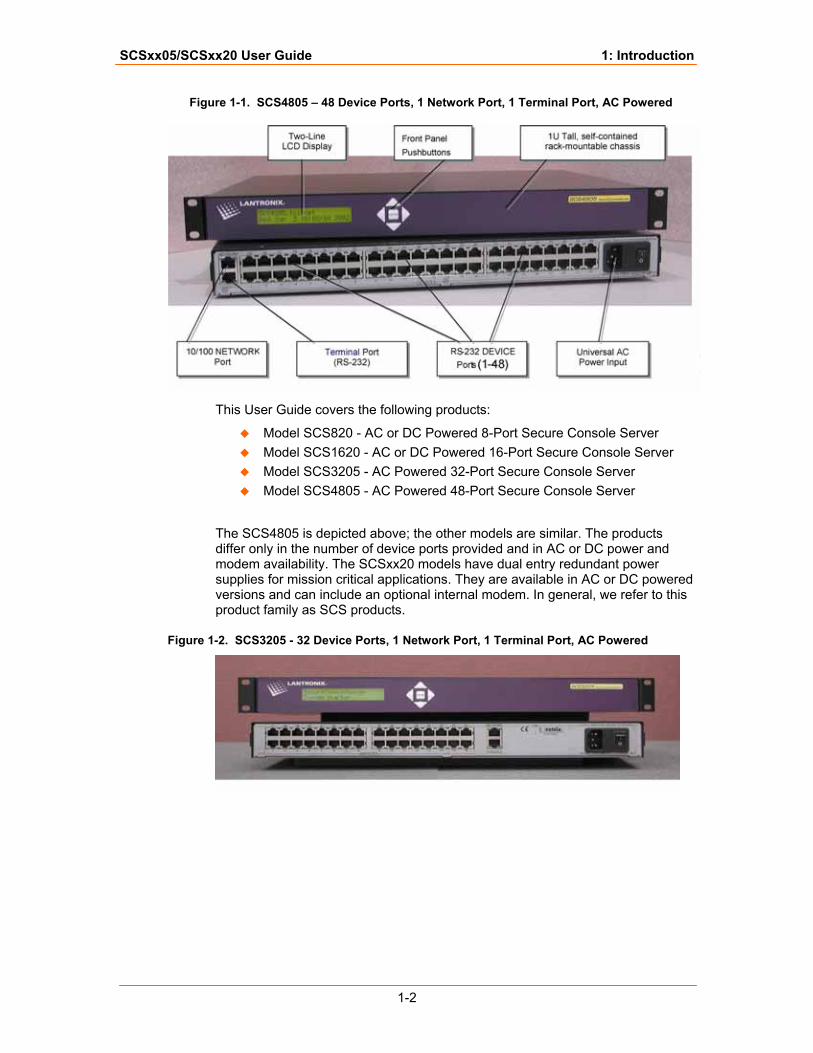
Figure 1-1. SCS4805 – 48 Device Ports, 1 Network Port, 1 Terminal Port, AC Powered
This User Guide covers the following products:
Model SCS820 - AC or DC Powered 8-Port Secure Console Server Model SCS1620 - AC or DC Powered 16-Port Secure Console Server Model SCS3205 - AC Powered 32-Port Secure Console Server Model SCS4805 - AC Powered 48-Port Secure Console Server
The SCS4805 is depicted above; the other models are similar. The products differ only in the number of device ports provided and in AC or DC power and modem availability. The SCSxx20 models have dual entry redundant power supplies for mission critical applications. They are available in AC or DC powered versions and can include an optional internal modem. In general, we refer to this product family as SCS products.
Figure 1-2. SCS3205 - 32 Device Ports, 1 Network Port, 1 Terminal Port, AC Powered
SCSxx05/SCSxx20 User Guide 1: Introduction
1-3
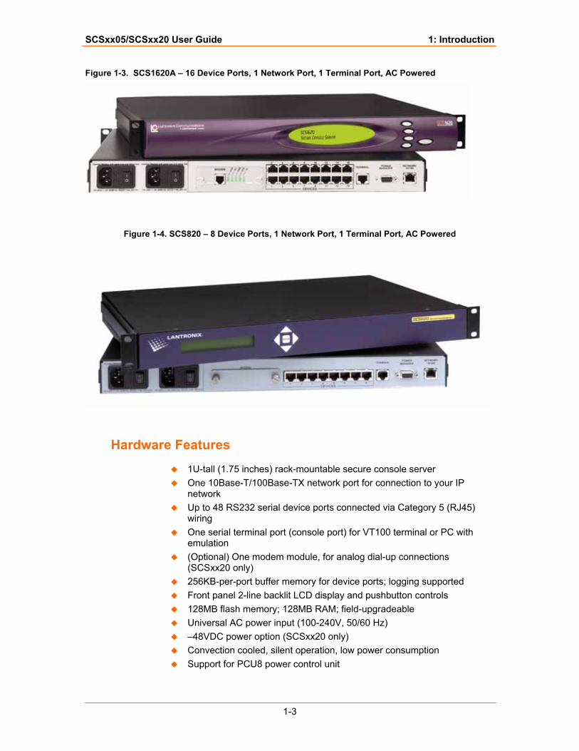
Figure 1-3. SCS1620A – 16 Device Ports, 1 Network Port, 1 Terminal Port, AC Powered
Figure 1-4. SCS820 – 8 Device Ports, 1 Network Port, 1 Terminal Port, AC Powered
Hardware Features
1U-tall (1.75 inches) rack-mountable secure console server One 10Base-T/100Base-TX network port for connection to your IP
network Up to 48 RS232 serial device ports connected via Category 5 (RJ45)
wiring One serial terminal port (console port) for VT100 terminal or PC with
emulation (Optional) One modem module, for analog dial-up connections
(SCSxx20 only) 256KB-per-port buffer memory for device ports; logging supported Front panel 2-line backlit LCD display and pushbutton controls 128MB flash memory; 128MB RAM; field-upgradeable Universal AC power input (100-240V, 50/60 Hz) –48VDC power option (SCSxx20 only) Convection cooled, silent operation, low power consumption Support for PCU8 power control unit
SCSxx05/SCSxx20 User Guide 1: Introduction
1-4
System Features
Ability to connect up to 48 RS-232 serial consoles 10Base-T/100Base-TX IP network compatible Buffer logging to file ID/Password security, configurable access rights Email notification Secure shell (SSH) security Open Lightweight Directory Access Protocol (LDAP) Network File System (NFS) support Network Information Service (NIS) capable for centrally managed
permissions Ability to Telnet to a serial port by IP address per port or by IP address
and TCP port number Ability to work with an external modem (SCSxx05 and SCSxx20) and
optional internal modem (SCSxx20) No unintentional break ever sent to attached servers (Solaris Ready
Certified) Simultaneous access on the same port - "listen" mode Local access through terminal port Built-in setup routine for simple setup and administration Web administration (using any modern browser)
Protocol Support
The SCS supports the TCP/IP network protocol as well as:
SSH, Telnet, and PPP for connections in and out of the SCS DNS for text-to-IP address name resolution SNMP for remote monitoring and management FTP for file transfers and firmware upgrades TFTP for firmware upgrades DHCP for IP address assignment HTTP/HTTPS for easy browser-based configuration NTP for time synchronization LDAP, NIS, RADIUS, CHAP, and PAP for user authentication
CHAP (Challenge Handshake Authentication Protocol)
A secure protocol for connecting to a system; more secure than the PAP.
DHCP (Dynamic Host Configuration Protocol)
Internet protocol for automating the configuration of computers that use TCP/IP.
DNS (Domain Name Servers)
A system that allows a network nameserver translate text host names into numeric IP addresses.
SCSxx05/SCSxx20 User Guide 1: Introduction
1-5
LDAP (Lightweight Directory Access Protocol)
A set of protocols for accessing information directories.
NFS (Network File System)
A protocol that allows file sharing across a network.
NIS (Network Information System)
A network-naming and administration system for smaller networks.
NTP (Network Time Protocol)
A protocol used to synchronize time on networked computers and equipment.
PAP (Password Authentication Protocol)
A method of user authentication in which the username and password are transmitted over a network and compared to a table of name-password pairs.
PPP (Point to Point Protocol)
A mechanism for creating and running IP and other network protocols over a serial link.
RADIUS (Remote Authentication Dial-In User Service)
An authentication and accounting system used by many Internet Service Providers (ISPs).
SNMP (Simple Network Management Protocol)
Commands that allow system administrators to monitor and manage nodes on a LAN (Local Area Network) and respond to queries from other network hosts. One community name can be configured with read/write access.
SSH (Secure Shell)
A secure transport protocol based on public-key cryptography.
Telnet
A terminal protocol that provides an easy-to-use method of creating terminal connections to a network host.
System Components
All system components are enclosed in a rack-mountable metal chassis. The chassis has 8, 16, 32, or 48 device ports, one terminal port, and one network port. An optional modem module is available for the SCSxx20 that you can add at any time. The front panel features an LCD display and pushbuttons for access to some system information.
Connection Formats
All physical connections to the product are made to the rear panel using industry-standard cabling and connectors. All serial connections and network connections use conventional Category 5 (Cat5) cabling (RJ45 jacks). Required cables and adapters for certain servers, switches, and other products are available from Lantronix (see http://www.lantronix.com/.)
Serial Devices
SCSxx05/SCSxx20 User Guide 1: Introduction
1-6
All devices attached to both the device ports and the terminal port must support the RS-232C (EIA-232) standard. Category 5 cabling with RJ45 connections is used for the device port connections and for the terminal port.
Device ports (numbered from port 1 to port 48) support seven baud rate options: 2400, 4800, 9600, 19200, 38400, 57600, and 115200 baud.
Network The SCS network interface is a 10Base-T/100Base-TX connector, for use with a conventional TCP/IP network using standard RJ45-terminated Category 5 cables. The system administrator must configure the network parameters before the SCS can be accessed over the network.
Modem (SCSxx20) The optional modem module connects to a conventional telephone line using standard RJ11 modular telephone cable. The analog modem on the card connects at speeds up to 38,400 baud. Any PPP features require a modem.
With the modem installed, the SCSxx20 supports:
Plain Text TTY PPP connection, with PAP or CHAP authentication Callback connection
Note: Both the SCSxx05 and the SCSxx20 can work with an external modem.
Power Manager The SCSxx20 has an extra power manager port for connection to the Lantronix Power Control Unit (PCU8). However, any available device port may be used as the power manager port on the SCSxx05 and SCSxx20.
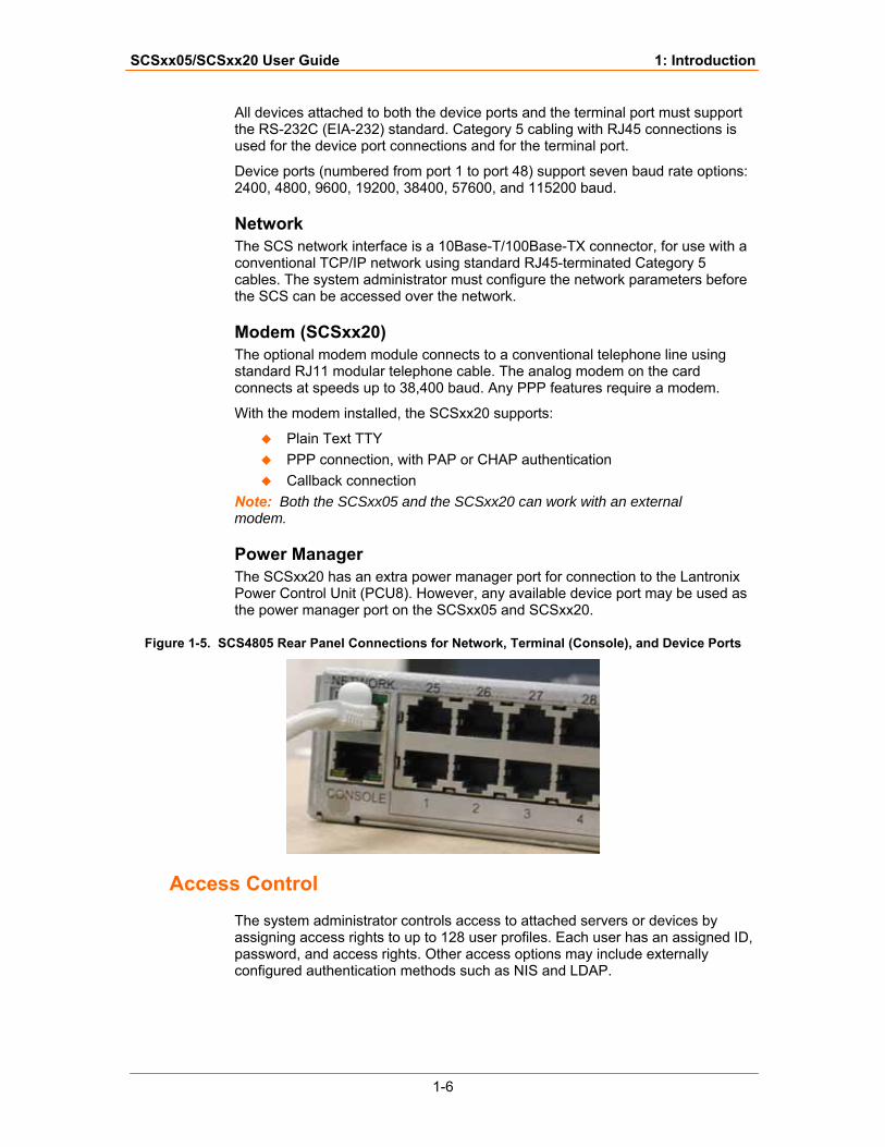
Figure 1-5. SCS4805 Rear Panel Connections for Network, Terminal (Console), and Device Ports
Access Control
The system administrator controls access to attached servers or devices by assigning access rights to up to 128 user profiles. Each user has an assigned ID, password, and access rights. Other access options may include externally configured authentication methods such as NIS and LDAP.
SCSxx05/SCSxx20 User Guide 1: Introduction
1-7
Device Port Buffer
The SCS products support port data buffering of the messages on the system's device ports. Port buffers are enabled by default.
256K FIFO Buffer Each device port stores 256 KB (approximately 400 screens) of I/O data in a true FIFO buffer. You may view this data while the user is not directly interacting with the attached device.
Buffered data is not normally stored in memory and will be lost in the event of a power failure if it is not logged using an NFS mount solution (see Port Data Logging, below). If the buffer data overflows the buffer capacity, only the oldest data will be lost, and only in the amount of overrun (not in large blocks of memory).
Port Data Logging The SCS supports real-time data logging for each device port. The port can save the data log to a file, send an email notification of an issue, or take no action.
SAVE (a system administrator command, discussed later) does not affect the buffer log files. Logging the data to an NFS mount location ensures that the device port data will be maintained (elsewhere) in the event of a power failure.
Logging to File Data can be logged either to a file on the SCS or to a file on a remote NFS server. Data logged to a local SCS file is limited in size by the available space on the SCS, and may be lost in the event of a power loss. Data logged to a file on an NFS server does not have these limitations. The system administrator can define the path for logged data on a port-by-port basis and configure file size and number of files per port for each logging event.
Email Notification The system administrator can configure the device log to automatically send an email alert message to the appropriate parties indicating a particular error. The email is triggered when a user-defined number of characters in the log from your server or device is exceeded.
SCSxx05/SCSxx20 User Guide 1: Introduction
1-8
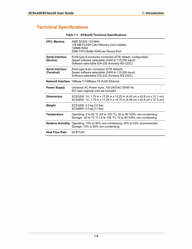
Technical Specifications Table 1-1. SCSxx05 Technical Specifications
CPU, Memory AMD SC520 133 MHz 128 MB FLASH Card Memory (non-volatile) 128MB RAM 256K FIFO Buffer RAM per Device Port
Serial Interface (Device)
RJ45-type 8-conductor connector (DTE default; configurable) Speed software selectable (2400 to 115,200 baud) Software selectable EIA-232 (formerly RS-232C)
Serial Interface (Terminal)
RJ45-type 8-pin connector (DTE default) Speed software selectable (2400 to 115,200 baud) Software selectable EIA-232 (formerly RS-232C)
Network Interface 10Base-T/100Base-TX RJ45 Ethernet
Power Supply Universal AC Power input, 100-240VAC 50/60 Hz IEC-type regional cord set included
Dimensions SCS3205: 1U, 1.75 in x 17.25 in x 12.25 in (4.45 cm x 43.8 cm x 31.1 cm)SCS4805: 1U, 1.75 in x 17.25 in x 14.75 in (4.45 cm x 43.8 cm x 37.5 cm)
Weight SCS3205: 4.5 kg (10 lbs) SCS4805: 5.0 kg (11 lbs)
Temperature Operating: 0 to 50 °C (32 to 122 °F), 30 to 90 %RH, non-condensing Storage: -20 to 70 °C (-4 to 158 °F), 10 to 90 %RH, non-condensing
Relative Humidity Operating: 10% to 90% non-condensing; 40% to 60% recommended Storage: 10% to 90% non-condensing
Heat Flow Rate 62 BTU/hr.
SCSxx05/SCSxx20 User Guide 1: Introduction
1-9
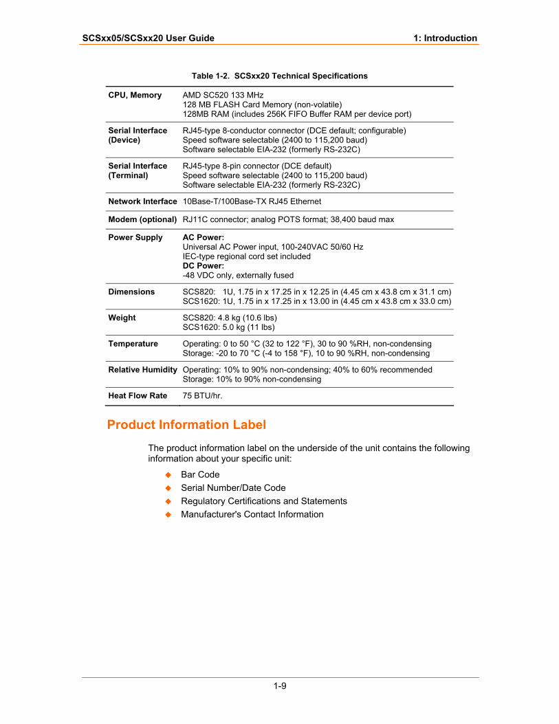
Table 1-2. SCSxx20 Technical Specifications
CPU, Memory AMD SC520 133 MHz 128 MB FLASH Card Memory (non-volatile) 128MB RAM (includes 256K FIFO Buffer RAM per device port)
Serial Interface (Device)
RJ45-type 8-conductor connector (DCE default; configurable) Speed software selectable (2400 to 115,200 baud) Software selectable EIA-232 (formerly RS-232C)
Serial Interface (Terminal)
RJ45-type 8-pin connector (DCE default) Speed software selectable (2400 to 115,200 baud) Software selectable EIA-232 (formerly RS-232C)
Network Interface 10Base-T/100Base-TX RJ45 Ethernet
Modem (optional) RJ11C connector; analog POTS format; 38,400 baud max
Power Supply AC Power: Universal AC Power input, 100-240VAC 50/60 Hz IEC-type regional cord set included DC Power: -48 VDC only, externally fused
Dimensions SCS820: 1U, 1.75 in x 17.25 in x 12.25 in (4.45 cm x 43.8 cm x 31.1 cm)SCS1620: 1U, 1.75 in x 17.25 in x 13.00 in (4.45 cm x 43.8 cm x 33.0 cm)
Weight SCS820: 4.8 kg (10.6 lbs) SCS1620: 5.0 kg (11 lbs)
Temperature Operating: 0 to 50 °C (32 to 122 °F), 30 to 90 %RH, non-condensing Storage: -20 to 70 °C (-4 to 158 °F), 10 to 90 %RH, non-condensing
Relative Humidity Operating: 10% to 90% non-condensing; 40% to 60% recommended Storage: 10% to 90% non-condensing
Heat Flow Rate 75 BTU/hr.
Product Information Label
The product information label on the underside of the unit contains the following information about your specific unit:
Bar Code Serial Number/Date Code Regulatory Certifications and Statements Manufacturer's Contact Information
SCSxx05/SCSxx20 User Guide 1: Introduction
1-10
System Resource Information
The SCS is programmable using OS-level commands and options. The system administrator configures the product using a command-line interface or one of several prepared scripts.
Numerous resources on the Internet (and elsewhere) provide information about security options, programming tools and techniques, and configuration advice. A few of the Internet sites are listed below:
SSH info: www.openSSH.org RFC's (the standards and details behind the Internet): www.rfc-editor.org PuTTY, a free Win32 Telnet/SSH Client (recommended):
http://www.chiark.greenend.org.uk/~sgtatham/putty/ Security: www.bastille-linux.org An online manual on Linux security:
http://www.linuxdoc.org/LDP/solrhe/Securing-Optimizing-Linux-RH-Edition-v1.3/
The following sites have more information about Linux (from basic to advanced):
www.kernel.org
www.tldp.org
http://www.linuxlinks.org/
2-1
22:: IInnssttaallllaattiioonn This chapter provides instructions for installing the SCS. It includes the following topics:
Topic PagePhysical Installation 2-1
Power 2-2
Connecting a Terminal 2-3
Connecting to a Device Port 2-4
Connecting the Network Port 2-5
Connecting the Modem Port (SCSxx20) 2-5
Power Manager Interface 2-6
Caution: To avoid physical and electrical hazards, please be sure to read Safety Precautions on page iii before installing the SCS.
Physical Installation
You can install the SCS either in an EIA-standard 19-inch rack (1U tall) or as a desktop unit. For desktop use, you may remove the rack mount brackets and use the four rubber feet provided.
Make all physical connections to the rear of the SCS. You may use the backlit front-panel LCD display during initial setup and to view current network settings.
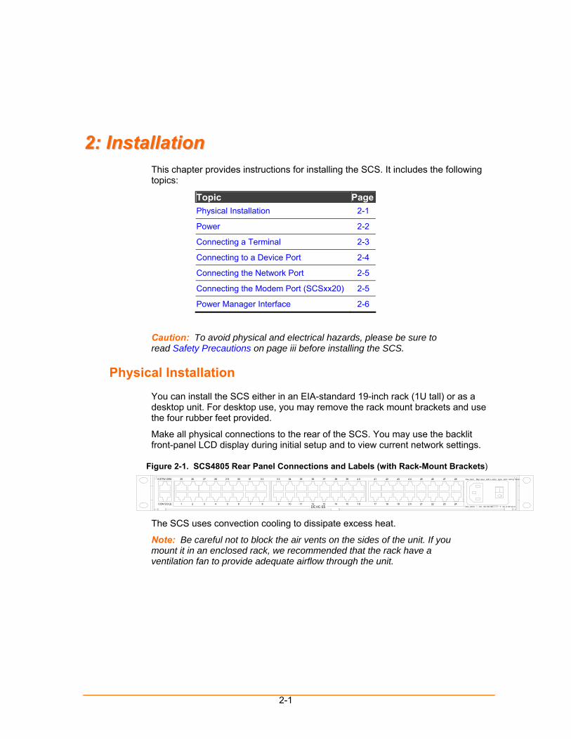
Figure 2-1. SCS4805 Rear Panel Connections and Labels (with Rack-Mount Brackets) 38
14CON SO LE 321 87654 12 13119 10DEVIC ES
25N ETW ORK 2726 302 928 3 231 35343 3 3736
1917 181 615 23 24212 0 22100- 240V ~, .5A , 50/ 60 Hz T 4A, 2 50 VA C
434 039 4241 454 4 4846 47 Cau ti on! Rep lac e wi th s am e ty pe and r ating fus e .
The SCS uses convection cooling to dissipate excess heat.
Note: Be careful not to block the air vents on the sides of the unit. If you mount it in an enclosed rack, we recommended that the rack have a ventilation fan to provide adequate airflow through the unit.
SCSxx05/SCSxx20 User Guide 2: Installation
2-2
Power
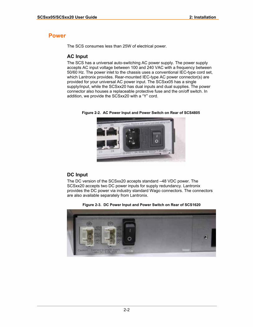
The SCS consumes less than 25W of electrical power.
AC Input The SCS has a universal auto-switching AC power supply. The power supply accepts AC input voltage between 100 and 240 VAC with a frequency between 50/60 Hz. The power inlet to the chassis uses a conventional IEC-type cord set, which Lantronix provides. Rear-mounted IEC-type AC power connector(s) are provided for your universal AC power input. The SCSxx05 has a single supply/input, while the SCSxx20 has dual inputs and dual supplies. The power connector also houses a replaceable protective fuse and the on/off switch. In addition, we provide the SCSxx20 with a “Y” cord.
Figure 2-2. AC Power Input and Power Switch on Rear of SCS4805
DC Input The DC version of the SCSxx20 accepts standard –48 VDC power. The SCSxx20 accepts two DC power inputs for supply redundancy. Lantronix provides the DC power via industry standard Wago connectors. The connectors are also available separately from Lantronix.
Figure 2-3. DC Power Input and Power Switch on Rear of SCS1620
SCSxx05/SCSxx20 User Guide 2: Installation
2-3
Connecting a Terminal
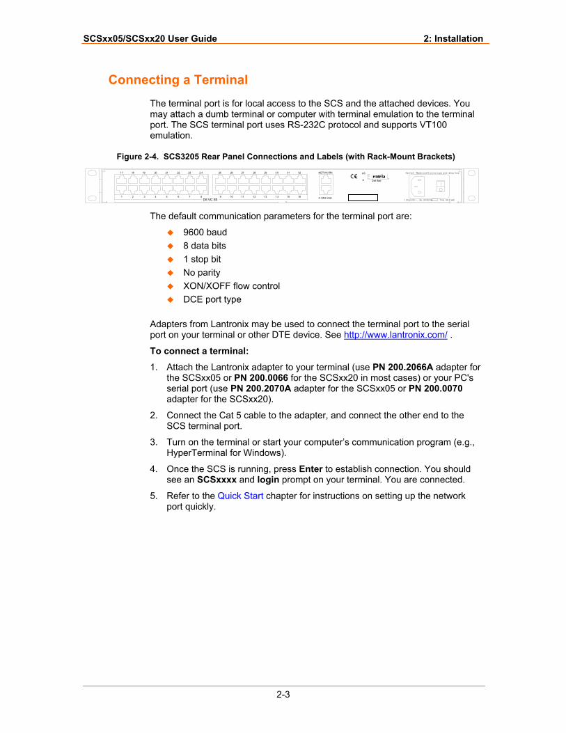
The terminal port is for local access to the SCS and the attached devices. You may attach a dumb terminal or computer with terminal emulation to the terminal port. The SCS terminal port uses RS-232C protocol and supports VT100 emulation.
Figure 2-4. SCS3205 Rear Panel Connections and Labels (with Rack-Mount Brackets)
431 2 976 85DE VIC ES
1 4131210 11
1 7 1918 20 252321 22 2 4 26 27 2928 3 0
1 00-24 0V ~ , .3A , 50/ 60 Hz1615 C ONS OLE
T 4A , 25 0 VAC
31 32 NETWO RK
entelaCert ifiedC
®
US Caut ion! Repla c e wi th s a m e t y pe and r ating fus e.
The default communication parameters for the te
9600 baud 8 data bits 1 stop bit No parity XON/XOFF flow control DCE port type
Adapters from Lantronix may be used to connectport on your terminal or other DTE device. See h
To connect a terminal:
1. Attach the Lantronix adapter to your terminalthe SCSxx05 or PN 200.0066 for the SCSxx2serial port (use PN 200.2070A adapter for theadapter for the SCSxx20).
2. Connect the Cat 5 cable to the adapter, and cSCS terminal port.
3. Turn on the terminal or start your computer’sHyperTerminal for Windows).
4. Once the SCS is running, press Enter to estasee an SCSxxxx and login prompt on your t
5. Refer to the Quick Start chapter for instructioport quickly.
rminal port are:
the terminal port to the serial ttp://www.lantronix.com/ .
(use PN 200.2066A adapter for 0 in most cases) or your PC's SCSxx05 or PN 200.0070
onnect the other end to the
communication program (e.g.,
blish connection. You should erminal. You are connected.
ns on setting up the network
SCSxx05/SCSxx20 User Guide 2: Installation
2-4
Connecting to a Device Port
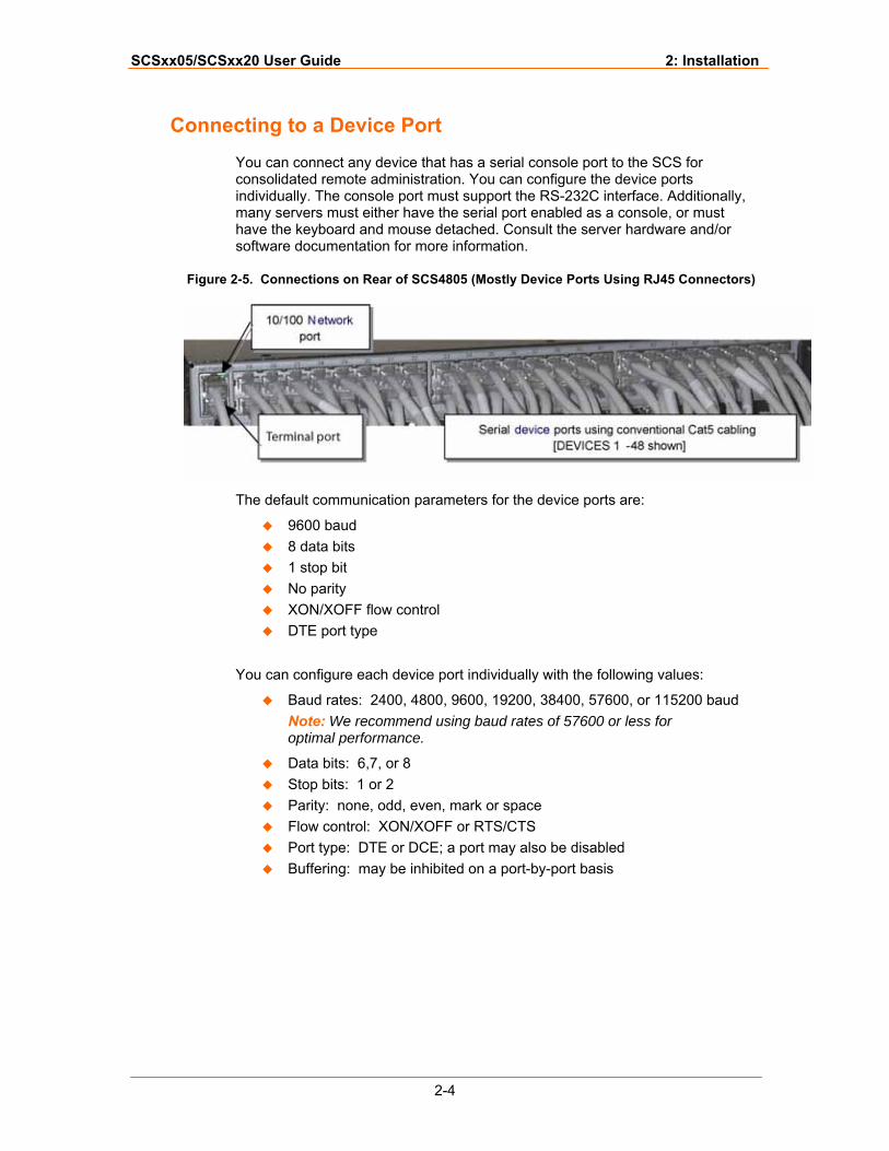
You can connect any device that has a serial console port to the SCS for consolidated remote administration. You can configure the device ports individually. The console port must support the RS-232C interface. Additionally, many servers must either have the serial port enabled as a console, or must have the keyboard and mouse detached. Consult the server hardware and/or software documentation for more information.
Figure 2-5. Connections on Rear of SCS4805 (Mostly Device Ports Using RJ45 Connectors)
The default communication parameters for the device ports are:
9600 baud 8 data bits 1 stop bit No parity XON/XOFF flow control DTE port type
You can configure each device port individually with the following values:
Baud rates: 2400, 4800, 9600, 19200, 38400, 57600, or 115200 baud Note: We recommend using baud rates of 57600 or less for optimal performance.
Data bits: 6,7, or 8 Stop bits: 1 or 2 Parity: none, odd, even, mark or space Flow control: XON/XOFF or RTS/CTS Port type: DTE or DCE; a port may also be disabled Buffering: may be inhibited on a port-by-port basis
SCSxx05/SCSxx20 User Guide 2: Installation
2-5
Connecting the Network Port
The SCS’s network port (10Base-T/100Base-TX) allows remote access to the attached devices and the system administrative functions.
You must first set up the network parameters for the network port before you can reach the SCS remotely. You can change the network parameters from the front panel of the SCS, or you may Telnet to the default address. Refer to the Quick Start chapter for instructions.
Connecting the Modem Port (SCSxx20)
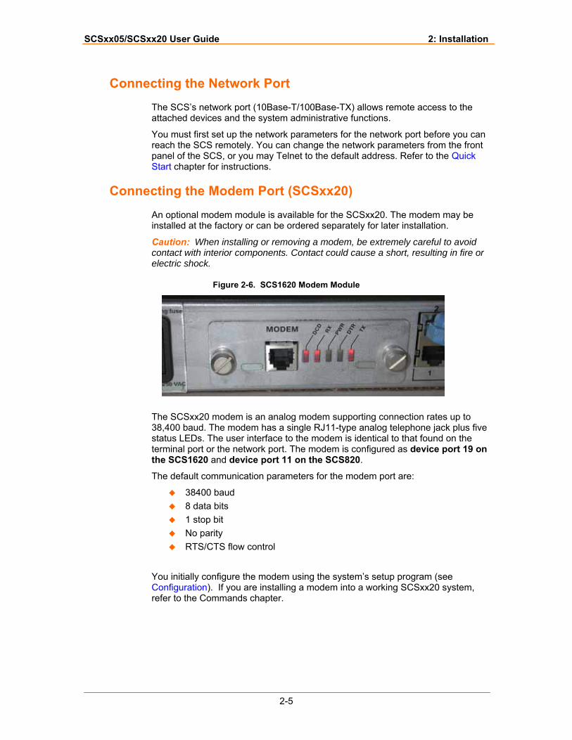
An optional modem module is available for the SCSxx20. The modem may be installed at the factory or can be ordered separately for later installation.
Caution: When installing or removing a modem, be extremely careful to avoid contact with interior components. Contact could cause a short, resulting in fire or electric shock.
Figure 2-6. SCS1620 Modem Module
The SCSxx20 modem is an analog modem supporting connection rates up to 38,400 baud. The modem has a single RJ11-type analog telephone jack plus five status LEDs. The user interface to the modem is identical to that found on the terminal port or the network port. The modem is configured as device port 19 on the SCS1620 and device port 11 on the SCS820.
The default communication parameters for the modem port are:
38400 baud 8 data bits 1 stop bit No parity RTS/CTS flow control
You initially configure the modem using the system’s setup program (see Configuration). If you are installing a modem into a working SCSxx20 system, refer to the Commands chapter.
SCSxx05/SCSxx20 User Guide 2: Installation
2-6
Power Manager Interface
The SCSxx20 has a dedicated port for the Lantronix PCU8 Power Control Unit. With the SCSxx05 (and the SCSxx20, if desired), you may use any available device port. The PCU8 uses a DB9 connector on its serial connector and requires a Part Number 200.0069 DB9 to RJ45 adapter for that connection. (Lantronix supplies one such adapter with each PCU8 system).
The required (default of PCU8) communication parameters for a device port for use as a power manager port are:
9600 baud 8 data bits 1 stop bit No parity XON/XOFF flow control DTE port type
Refer to the PCU8 documentation for baud rate options.
3-1
33:: QQuuiicckk SSttaarrtt This chapter helps you get your IP network port up and running quickly, so you may administer the SCS using your network. There are two methods to quick start the network connections:
You may use the front panel display and buttons, or You may use your existing IP network, accessing the default IP address
Once you have identified your IP network parameters to the SCS, you can use your IP network connections to configure and administer it.
Note: Be sure to address security issues (access and passwords) first when administering the system. See the Commands chapter for a list of the commands, including steps to change the system's passwords.
This chapter includes the following topics:
Topic Page Before You Begin 3-1
Method #1 – Using the Front Panel Display 3-2
Method # 2- Using Telnet. 3-4
Before You Begin
Before you begin, make sure you know:
An IP address that will be unique and valid on your network (Out of the box, the IP network port identity has a generic default value of 10.0.0.1.)
Subnet mask (generic default value is 255.0.0.0) Gateway DNS settings Date, time, and time zone Terminal port settings
Make sure the SCS is plugged in to power and is turned on.
SCSxx05/SCSxx20 User Guide 3: Quick Start
3-2
Method #1 – Using the Front Panel Display
You can use the front panel display and pushbuttons to set up the basic network interface. The system administrator can then access the SCS using your existing IP network.
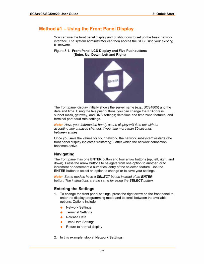
Figure 3-1. Front Panel LCD Display and Five Pushbuttons (Enter, Up, Down, Left and Right)
The front panel display initially shows the server name (e.g., SCS4805) and the date and time. Using the five pushbuttons, you can change the IP Address, subnet mask, gateway, and DNS settings; date/time and time zone features; and terminal port baud rate settings.
Note: Have your information handy as the display will time out without accepting any unsaved changes if you take more than 30 seconds between entries.
Once you save the values for your network, the network subsystem restarts (the front panel display indicates “restarting”), after which the network connection becomes active.
Navigating The front panel has one ENTER button and four arrow buttons (up, left, right, and down). Press the arrow buttons to navigate from one option to another, or to increment or decrement a numerical entry of the selected feature. Use the ENTER button to select an option to change or to save your settings.
Note: Some models have a SELECT button instead of an ENTER button. The instructions are the same for using the SELECT button.
Entering the Settings 1. To change the front panel settings, press the right arrow on the front panel to
enter the display programming mode and to scroll between the available options. Options include:
Network Settings Terminal Settings Release Date Time/Date Settings Return to normal display
2. In this example, stop at Network Settings.
SCSxx05/SCSxx20 User Guide 3: Quick Start
3-3
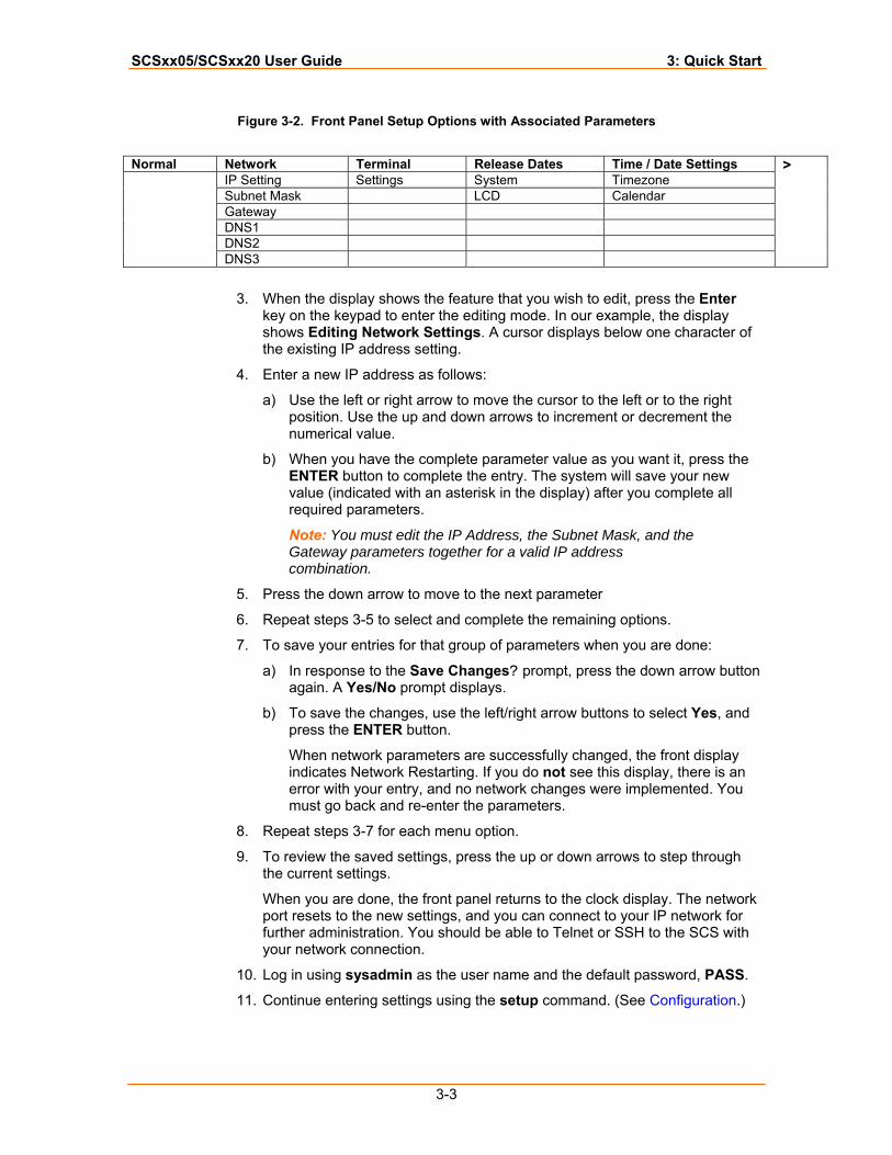
Figure 3-2. Front Panel Setup Options with Associated Parameters
Normal Network Terminal Release Dates Time / Date Settings
IP Setting Settings System Timezone Subnet Mask LCD Calendar Gateway DNS1 DNS2
DNS3
>
3. When the display shows the feature that you wish to edit, press the Enter
key on the keypad to enter the editing mode. In our example, the display shows Editing Network Settings. A cursor displays below one character of the existing IP address setting.
4. Enter a new IP address as follows:
a) Use the left or right arrow to move the cursor to the left or to the right position. Use the up and down arrows to increment or decrement the numerical value.
b) When you have the complete parameter value as you want it, press the ENTER button to complete the entry. The system will save your new value (indicated with an asterisk in the display) after you complete all required parameters.
Note: You must edit the IP Address, the Subnet Mask, and the Gateway parameters together for a valid IP address combination.
5. Press the down arrow to move to the next parameter
6. Repeat steps 3-5 to select and complete the remaining options.
7. To save your entries for that group of parameters when you are done:
a) In response to the Save Changes? prompt, press the down arrow button again. A Yes/No prompt displays.
b) To save the changes, use the left/right arrow buttons to select Yes, and press the ENTER button.
When network parameters are successfully changed, the front display indicates Network Restarting. If you do not see this display, there is an error with your entry, and no network changes were implemented. You must go back and re-enter the parameters.
8. Repeat steps 3-7 for each menu option.
9. To review the saved settings, press the up or down arrows to step through the current settings.
When you are done, the front panel returns to the clock display. The network port resets to the new settings, and you can connect to your IP network for further administration. You should be able to Telnet or SSH to the SCS with your network connection.
10. Log in using sysadmin as the user name and the default password, PASS.
11. Continue entering settings using the setup command. (See Configuration.)
SCSxx05/SCSxx20 User Guide 3: Quick Start
3-4
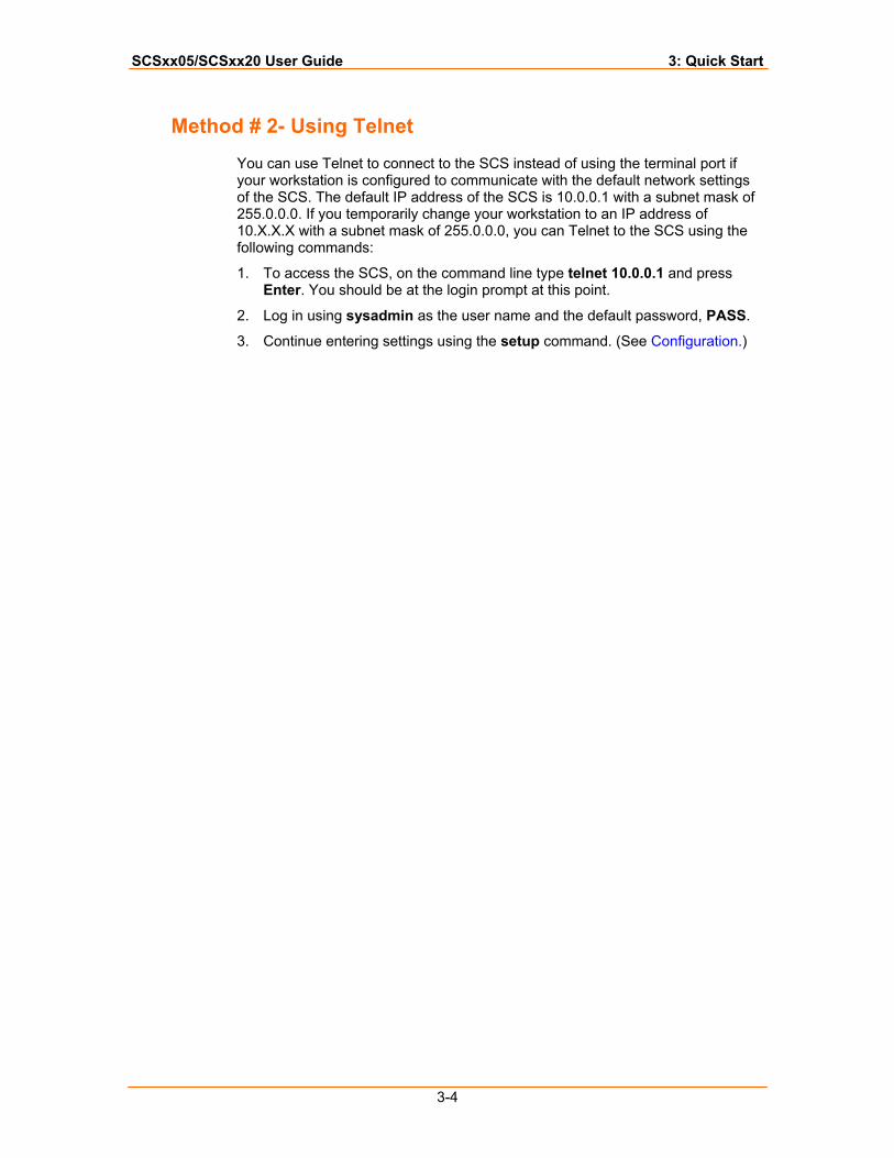
Method # 2- Using Telnet
You can use Telnet to connect to the SCS instead of using the terminal port if your workstation is configured to communicate with the default network settings of the SCS. The default IP address of the SCS is 10.0.0.1 with a subnet mask of 255.0.0.0. If you temporarily change your workstation to an IP address of 10.X.X.X with a subnet mask of 255.0.0.0, you can Telnet to the SCS using the following commands:
1. To access the SCS, on the command line type telnet 10.0.0.1 and press Enter. You should be at the login prompt at this point.
2. Log in using sysadmin as the user name and the default password, PASS.
3. Continue entering settings using the setup command. (See Configuration.)
4-1
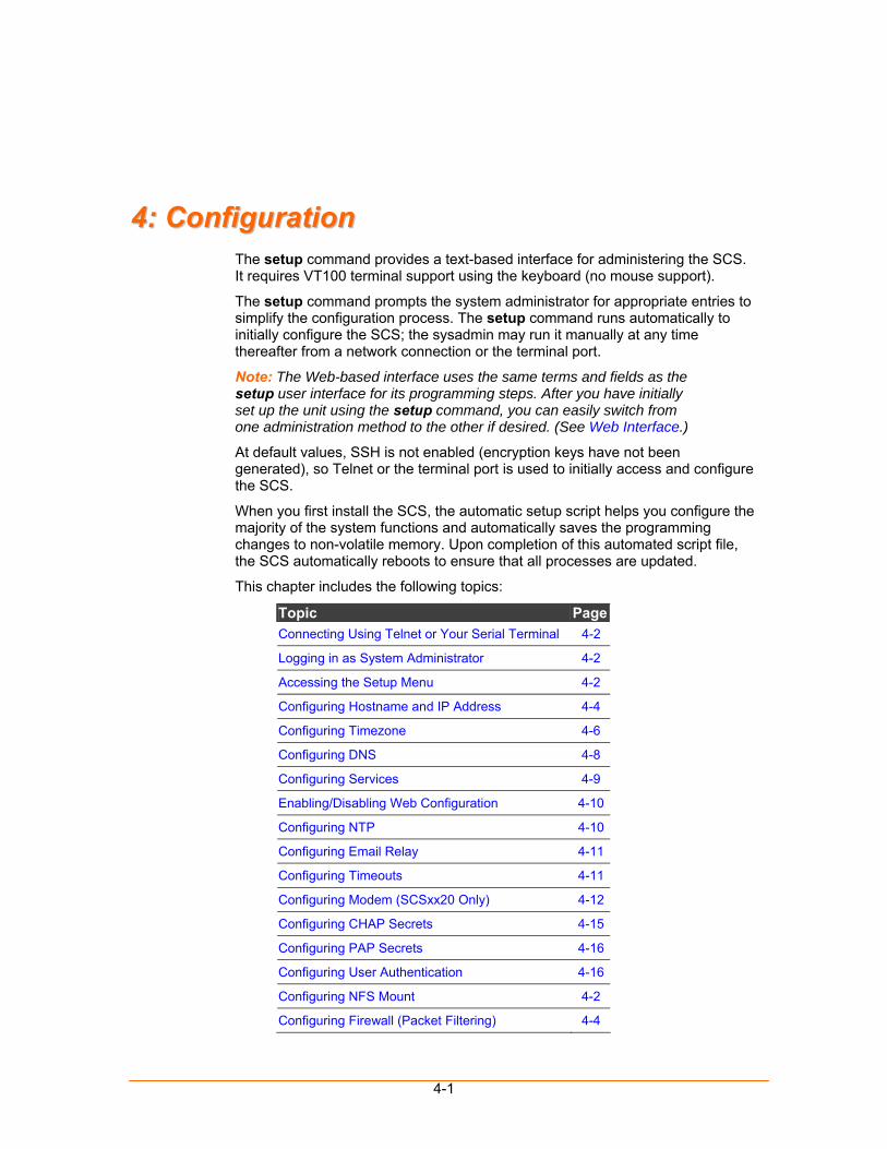
44:: CCoonnffiigguurraattiioonn The setup command provides a text-based interface for administering the SCS. It requires VT100 terminal support using the keyboard (no mouse support).
The setup command prompts the system administrator for appropriate entries to simplify the configuration process. The setup command runs automatically to initially configure the SCS; the sysadmin may run it manually at any time thereafter from a network connection or the terminal port.
Note: The Web-based interface uses the same terms and fields as the setup user interface for its programming steps. After you have initially set up the unit using the setup command, you can easily switch from one administration method to the other if desired. (See Web Interface.)
At default values, SSH is not enabled (encryption keys have not been generated), so Telnet or the terminal port is used to initially access and configure the SCS.
When you first install the SCS, the automatic setup script helps you configure the majority of the system functions and automatically saves the programming changes to non-volatile memory. Upon completion of this automated script file, the SCS automatically reboots to ensure that all processes are updated.
This chapter includes the following topics:
Topic PageConnecting Using Telnet or Your Serial Terminal 4-2
Logging in as System Administrator 4-2
Accessing the Setup Menu 4-2
Configuring Hostname and IP Address 4-4
Configuring Timezone 4-6
Configuring DNS 4-8
Configuring Services 4-9
Enabling/Disabling Web Configuration 4-10
Configuring NTP 4-10
Configuring Email Relay 4-11
Configuring Timeouts 4-11
Configuring Modem (SCSxx20 Only) 4-12
Configuring CHAP Secrets 4-15
Configuring PAP Secrets 4-16
Configuring User Authentication 4-16
Configuring NFS Mount 4-2
Configuring Firewall (Packet Filtering) 4-4
SCSxx05/SCSxx20 User Guide 4: Configuration
4-2
Topic PageConfiguring Device Ports 4-5
Updating Software 4-14
Using Done 4-16
Saving 4-17
Rebooting 4-17
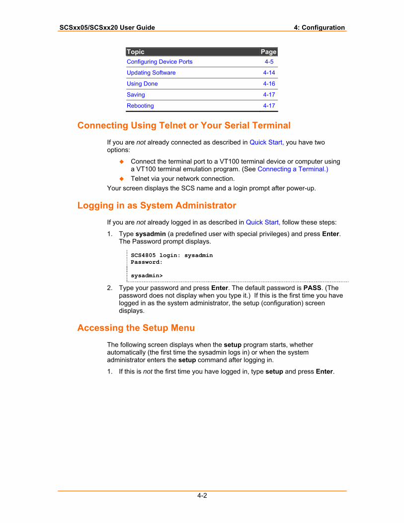
Connecting Using Telnet or Your Serial Terminal
If you are not already connected as described in Quick Start, you have two options:
Connect the terminal port to a VT100 terminal device or computer using a VT100 terminal emulation program. (See Connecting a Terminal.)
Telnet via your network connection. Your screen displays the SCS name and a login prompt after power-up.
Logging in as System Administrator
If you are not already logged in as described in Quick Start, follow these steps:
1. Type sysadmin (a predefined user with special privileges) and press Enter. The Password prompt displays.
SCS4805 login: sysadmin Password: sysadmin>
2. Type your password and press Enter. The default password is PASS. (The password does not display when you type it.) If this is the first time you have logged in as the system administrator, the setup (configuration) screen displays.
Accessing the Setup Menu
The following screen displays when the setup program starts, whether automatically (the first time the sysadmin logs in) or when the system administrator enters the setup command after logging in.
1. If this is not the first time you have logged in, type setup and press Enter.
SCSxx05/SCSxx20 User Guide 4: Configuration
4-3
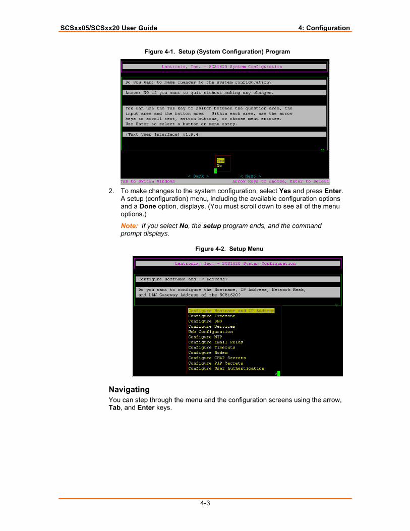
Figure 4-1. Setup (System Configuration) Program
2. To make changes to the system configuration, select Yes and press Enter.
A setup (configuration) menu, including the available configuration options and a Done option, displays. (You must scroll down to see all of the menu options.)
Note: If you select No, the setup program ends, and the command prompt displays.
Figure 4-2. Setup Menu
Navigating You can step through the menu and the configuration screens using the arrow, Tab, and Enter keys.
SCSxx05/SCSxx20 User Guide 4: Configuration
4-4
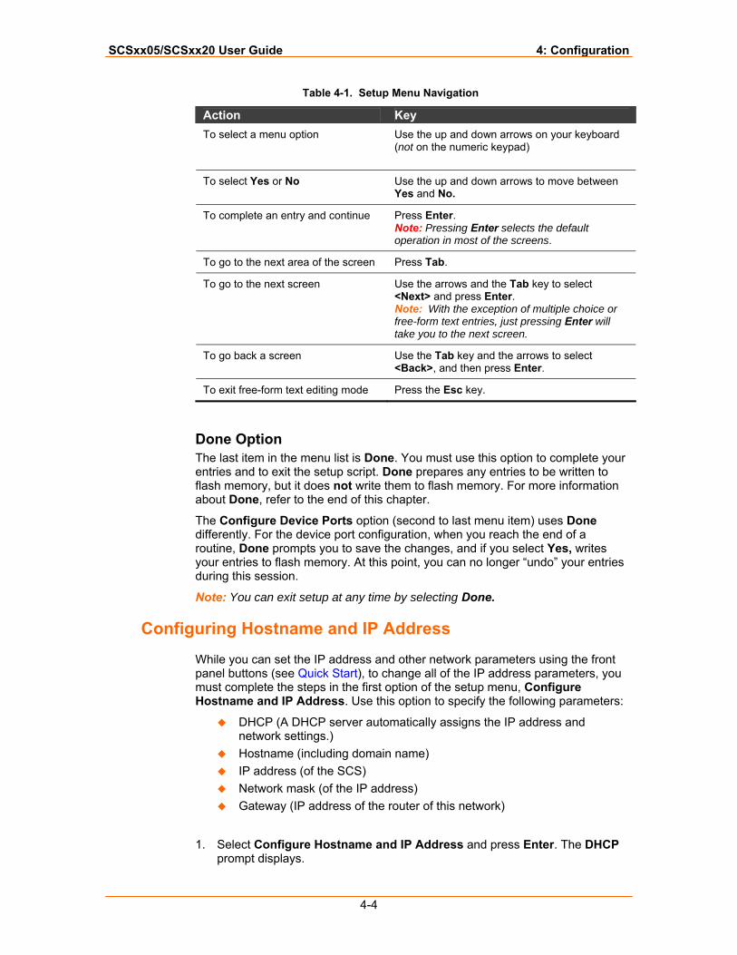
Table 4-1. Setup Menu Navigation
Done Option The last item in the menu list is Done. You must use this option to complete your entries and to exit the setup script. Done prepares any entries to be written to flash memory, but it does not write them to flash memory. For more information about Done, refer to the end of this chapter.
The Configure Device Ports option (second to last menu item) uses Done differently. For the device port configuration, when you reach the end of a routine, Done prompts you to save the changes, and if you select Yes, writes your entries to flash memory. At this point, you can no longer “undo” your entries during this session.
Note: You can exit setup at any time by selecting Done.
Configuring Hostname and IP Address
While you can set the IP address and other network parameters using the front panel buttons (see Quick Start), to change all of the IP address parameters, you must complete the steps in the first option of the setup menu, Configure Hostname and IP Address. Use this option to specify the following parameters:
DHCP (A DHCP server automatically assigns the IP address and network settings.)
Hostname (including domain name) IP address (of the SCS) Network mask (of the IP address) Gateway (IP address of the router of this network)
1. Select Configure Hostname and IP Address and press Enter. The DHCP prompt displays.
Action Key To select a menu option Use the up and down arrows on your keyboard
(not on the numeric keypad)
To select Yes or No Use the up and down arrows to move between Yes and No.
To complete an entry and continue Press Enter. Note: Pressing Enter selects the default operation in most of the screens.
To go to the next area of the screen Press Tab.
To go to the next screen Use the arrows and the Tab key to select <Next> and press Enter. Note: With the exception of multiple choice or free-form text entries, just pressing Enter will take you to the next screen.
To go back a screen Use the Tab key and the arrows to select <Back>, and then press Enter.
To exit free-form text editing mode Press the Esc key.
SCSxx05/SCSxx20 User Guide 4: Configuration
4-5
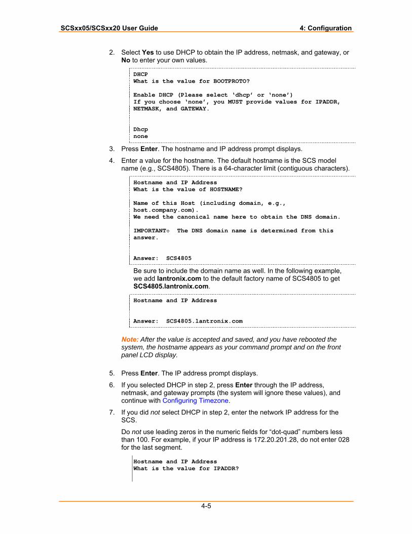
2. Select Yes to use DHCP to obtain the IP address, netmask, and gateway, or No to enter your own values.
DHCP What is the value for BOOTPROTO? Enable DHCP (Please select ‘dhcp’ or ‘none’) If you choose ‘none’, you MUST provide values for IPADDR, NETMASK, and GATEWAY. Dhcp none
3. Press Enter. The hostname and IP address prompt displays.
4. Enter a value for the hostname. The default hostname is the SCS model name (e.g., SCS4805). There is a 64-character limit (contiguous characters).
Hostname and IP Address What is the value of HOSTNAME? Name of this Host (including domain, e.g., host.company.com). We need the canonical name here to obtain the DNS domain. IMPORTANT: The DNS domain name is determined from this answer. Answer: SCS4805
Be sure to include the domain name as well. In the following example, we add lantronix.com to the default factory name of SCS4805 to get SCS4805.lantronix.com.
Hostname and IP Address Answer: SCS4805.lantronix.com
Note: After the value is accepted and saved, and you have rebooted the system, the hostname appears as your command prompt and on the front panel LCD display.
5. Press Enter. The IP address prompt displays.
6. If you selected DHCP in step 2, press Enter through the IP address, netmask, and gateway prompts (the system will ignore these values), and continue with Configuring Timezone.
7. If you did not select DHCP in step 2, enter the network IP address for the SCS.
Do not use leading zeros in the numeric fields for “dot-quad” numbers less than 100. For example, if your IP address is 172.20.201.28, do not enter 028 for the last segment.
Hostname and IP Address What is the value for IPADDR?
SCSxx05/SCSxx20 User Guide 4: Configuration
4-6
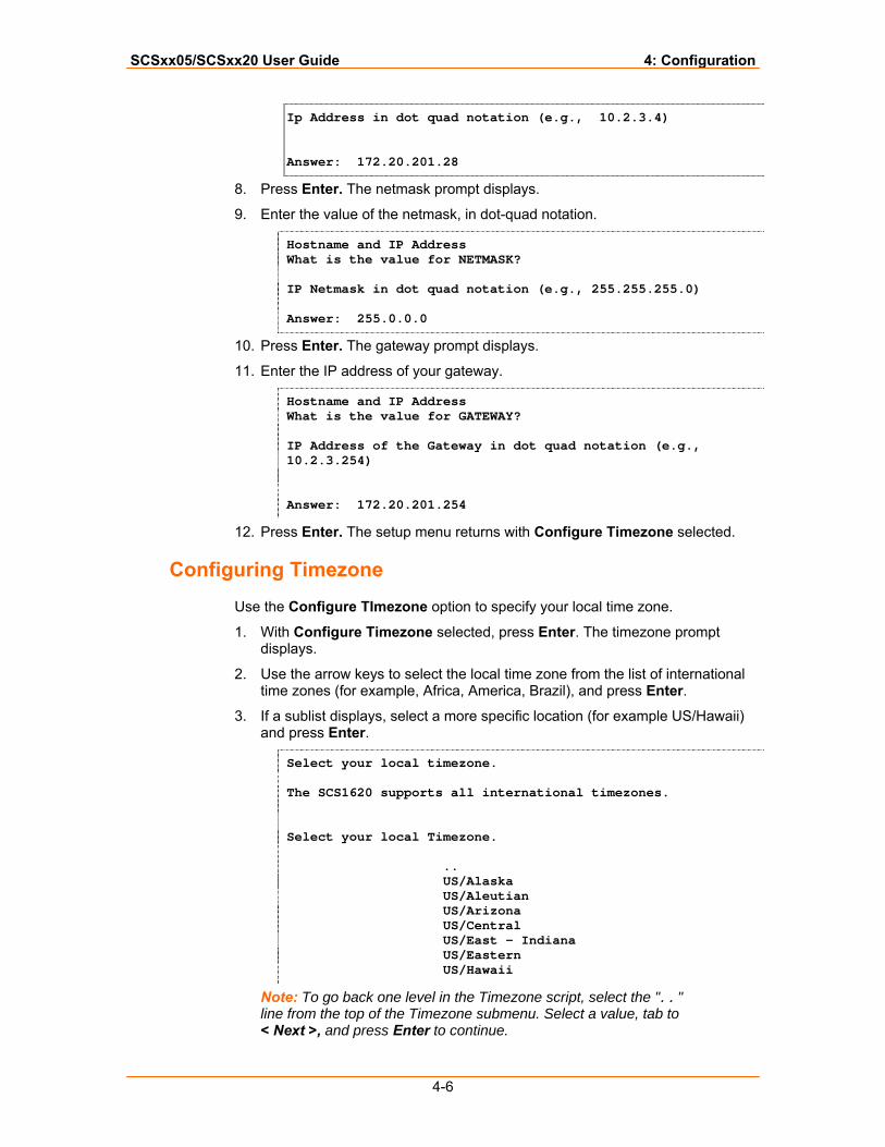
Ip Address in dot quad notation (e.g., 10.2.3.4) Answer: 172.20.201.28
8. Press Enter. The netmask prompt displays.
9. Enter the value of the netmask, in dot-quad notation.
Hostname and IP Address What is the value for NETMASK? IP Netmask in dot quad notation (e.g., 255.255.255.0) Answer: 255.0.0.0
10. Press Enter. The gateway prompt displays.
11. Enter the IP address of your gateway.
Hostname and IP Address What is the value for GATEWAY? IP Address of the Gateway in dot quad notation (e.g., 10.2.3.254) Answer: 172.20.201.254
12. Press Enter. The setup menu returns with Configure Timezone selected.
Configuring Timezone
Use the Configure TImezone option to specify your local time zone.
1. With Configure Timezone selected, press Enter. The timezone prompt displays.
2. Use the arrow keys to select the local time zone from the list of international time zones (for example, Africa, America, Brazil), and press Enter.
3. If a sublist displays, select a more specific location (for example US/Hawaii) and press Enter.
Select your local timezone. The SCS1620 supports all international timezones. Select your local Timezone. .. US/Alaska US/Aleutian US/Arizona US/Central US/East – Indiana US/Eastern US/Hawaii
Note: To go back one level in the Timezone script, select the ".." line from the top of the Timezone submenu. Select a value, tab to < Next >, and press Enter to continue.

SCSxx05/SCSxx20 User Guide 4: Configuration
4-7
SCSxx05/SCSxx20 User Guide 4: Configuration
4-8
4. At the end of the Timezone script, press Enter. The setup menu returns with Configure DNS selected.
At this point, you may continue with the next setup menu item, you may use the arrow keys to select another item in the list, or you may arrow down to Done to exit the setup script. (You can do this for any of the high level menu items.)
Configuring DNS
Use this option to configure the following parameters:
Primary DNS nameserver (required if you choose to configure DNS servers).
Secondary DNS nameserver (optional) Tertiary DNS nameserver (optional)
1. With Configure DNS selected, press Enter. The primary name server
prompt displays.
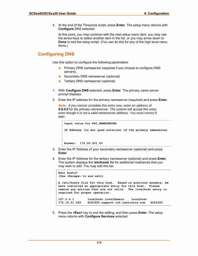
2. Enter the IP address for the primary nameserver (required) and press Enter.
Note: If you cannot complete this entry now, enter an address of 0.0.0.0 for the primary nameserver. The system will accept this entry even though it is not a valid nameserver address. You must correct it later.
Input value for PRI_NAMESERVER IP Address (in dot quad notation) of the primary nameserver Answer: 172.20.201.63
3. Enter the IP Address of your secondary nameserver (optional) and press Enter.
4. Enter the IP Address for the tertiary nameserver (optional) and press Enter. The system displays the /etc/hosts file for additional hostnames that you may wish to add. You may edit this list.
Edit hosts? (Use <Escape> to end edit) A /etc/hosts file for this host. Based on previous answers, we have installed an appropriate entry for this host. Please remove any entries that are not valid. The localhost entry is required for proper operation. 127.0.0.1 localhost.localdomain localhost 172.19.21.245 SCS1620.support.int.Lantronix.com SCS1620
5. Press the <Esc> key to end the editing, and then press Enter. The setup
menu returns with Configure Services selected.
SCSxx05/SCSxx20 User Guide 4: Configuration
4-9
Configuring Services
With this menu option, you enable or disable the following:
Syslog (system logging) (default is enabled) System logins using SSH (default is disabled) System logins using Telnet (default is enabled) Simple Network Management Protocol (SNMP Agent) (default is
disabled) 1. With Configure Services selected, press Enter. The syslog prompt displays.
2. Select Yes to enable or No (default) to disable syslog, and press Enter. The SSH logins prompt displays.
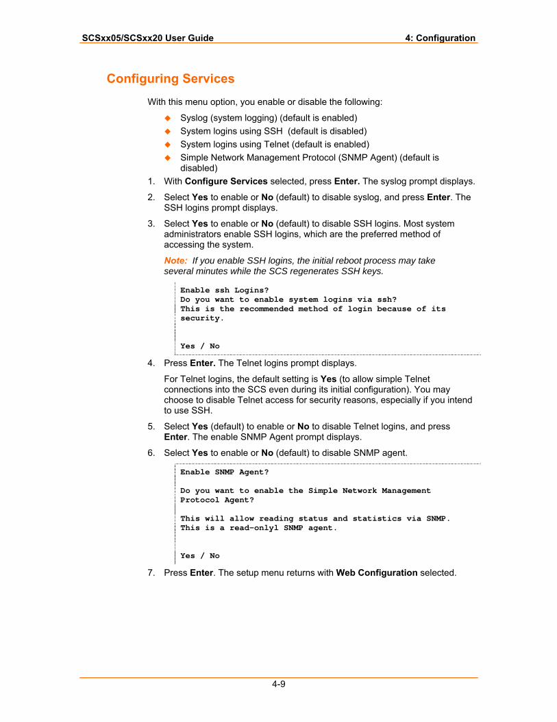
3. Select Yes to enable or No (default) to disable SSH logins. Most system administrators enable SSH logins, which are the preferred method of accessing the system.
Note: If you enable SSH logins, the initial reboot process may take several minutes while the SCS regenerates SSH keys.
Enable ssh Logins? Do you want to enable system logins via ssh? This is the recommended method of login because of its security. Yes / No
4. Press Enter. The Telnet logins prompt displays.
For Telnet logins, the default setting is Yes (to allow simple Telnet connections into the SCS even during its initial configuration). You may choose to disable Telnet access for security reasons, especially if you intend to use SSH.
5. Select Yes (default) to enable or No to disable Telnet logins, and press Enter. The enable SNMP Agent prompt displays.
6. Select Yes to enable or No (default) to disable SNMP agent.
Enable SNMP Agent? Do you want to enable the Simple Network Management Protocol Agent? This will allow reading status and statistics via SNMP. This is a read-onlyl SNMP agent. Yes / No
7. Press Enter. The setup menu returns with Web Configuration selected.
SCSxx05/SCSxx20 User Guide 4: Configuration
4-10
Enabling/Disabling Web Configuration
The SCS offers a Web-based configuration interface, which you can only access through your browser using SSL (Secure Sockets Layer) (https://). The Web interface has most of the same options as the console-based setup routine and may be useful for updating configuration options after you complete the initial setup.
This option enables or disables the ability to update the SCS configuration using the Web interface.
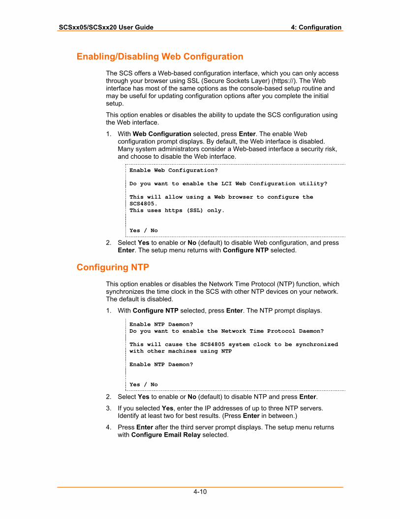
1. With Web Configuration selected, press Enter. The enable Web configuration prompt displays. By default, the Web interface is disabled. Many system administrators consider a Web-based interface a security risk, and choose to disable the Web interface.
Enable Web Configuration? Do you want to enable the LCI Web Configuration utility? This will allow using a Web browser to configure the SCS4805. This uses https (SSL) only. Yes / No
2. Select Yes to enable or No (default) to disable Web configuration, and press Enter. The setup menu returns with Configure NTP selected.
Configuring NTP
This option enables or disables the Network Time Protocol (NTP) function, which synchronizes the time clock in the SCS with other NTP devices on your network. The default is disabled.
1. With Configure NTP selected, press Enter. The NTP prompt displays.
Enable NTP Daemon? Do you want to enable the Network Time Protocol Daemon? This will cause the SCS4805 system clock to be synchronized with other machines using NTP Enable NTP Daemon? Yes / No
2. Select Yes to enable or No (default) to disable NTP and press Enter.
3. If you selected Yes, enter the IP addresses of up to three NTP servers. Identify at least two for best results. (Press Enter in between.)
4. Press Enter after the third server prompt displays. The setup menu returns with Configure Email Relay selected.
SCSxx05/SCSxx20 User Guide 4: Configuration
4-11
Configuring Email Relay
The SCS incorporates a mail transport agent for email delivery. Use this option to identify your network’s SMTP relay server.
1. With Configure Email Relay selected, press Enter.
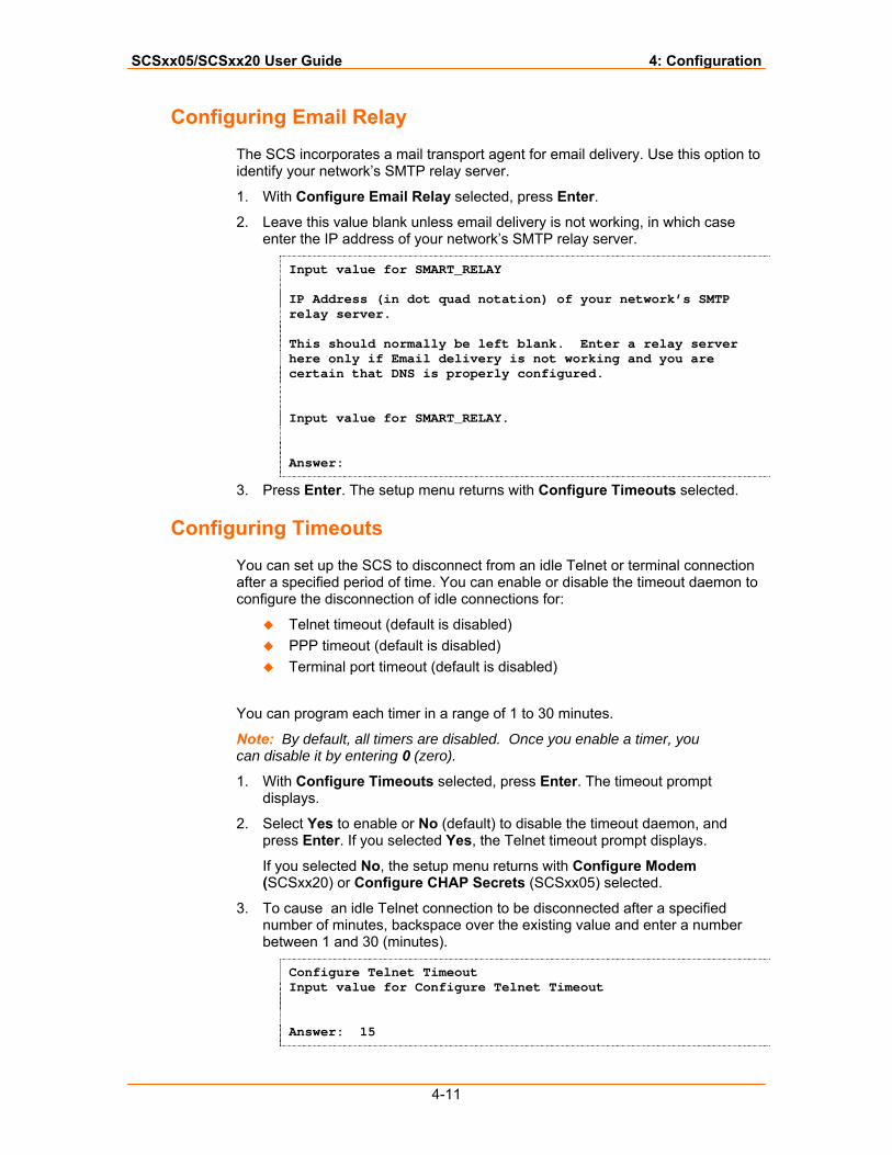
2. Leave this value blank unless email delivery is not working, in which case enter the IP address of your network’s SMTP relay server.
Input value for SMART_RELAY IP Address (in dot quad notation) of your network’s SMTP relay server. This should normally be left blank. Enter a relay server here only if Email delivery is not working and you are certain that DNS is properly configured. Input value for SMART_RELAY. Answer:
3. Press Enter. The setup menu returns with Configure Timeouts selected.
Configuring Timeouts
You can set up the SCS to disconnect from an idle Telnet or terminal connection after a specified period of time. You can enable or disable the timeout daemon to configure the disconnection of idle connections for:
Telnet timeout (default is disabled) PPP timeout (default is disabled) Terminal port timeout (default is disabled)
You can program each timer in a range of 1 to 30 minutes.
Note: By default, all timers are disabled. Once you enable a timer, you can disable it by entering 0 (zero).
1. With Configure Timeouts selected, press Enter. The timeout prompt displays.
2. Select Yes to enable or No (default) to disable the timeout daemon, and press Enter. If you selected Yes, the Telnet timeout prompt displays.
If you selected No, the setup menu returns with Configure Modem (SCSxx20) or Configure CHAP Secrets (SCSxx05) selected.
3. To cause an idle Telnet connection to be disconnected after a specified number of minutes, backspace over the existing value and enter a number between 1 and 30 (minutes).
Configure Telnet Timeout Input value for Configure Telnet Timeout Answer: 15
SCSxx05/SCSxx20 User Guide 4: Configuration
4-12
4. Press Enter. The PPP timeout prompt displays.
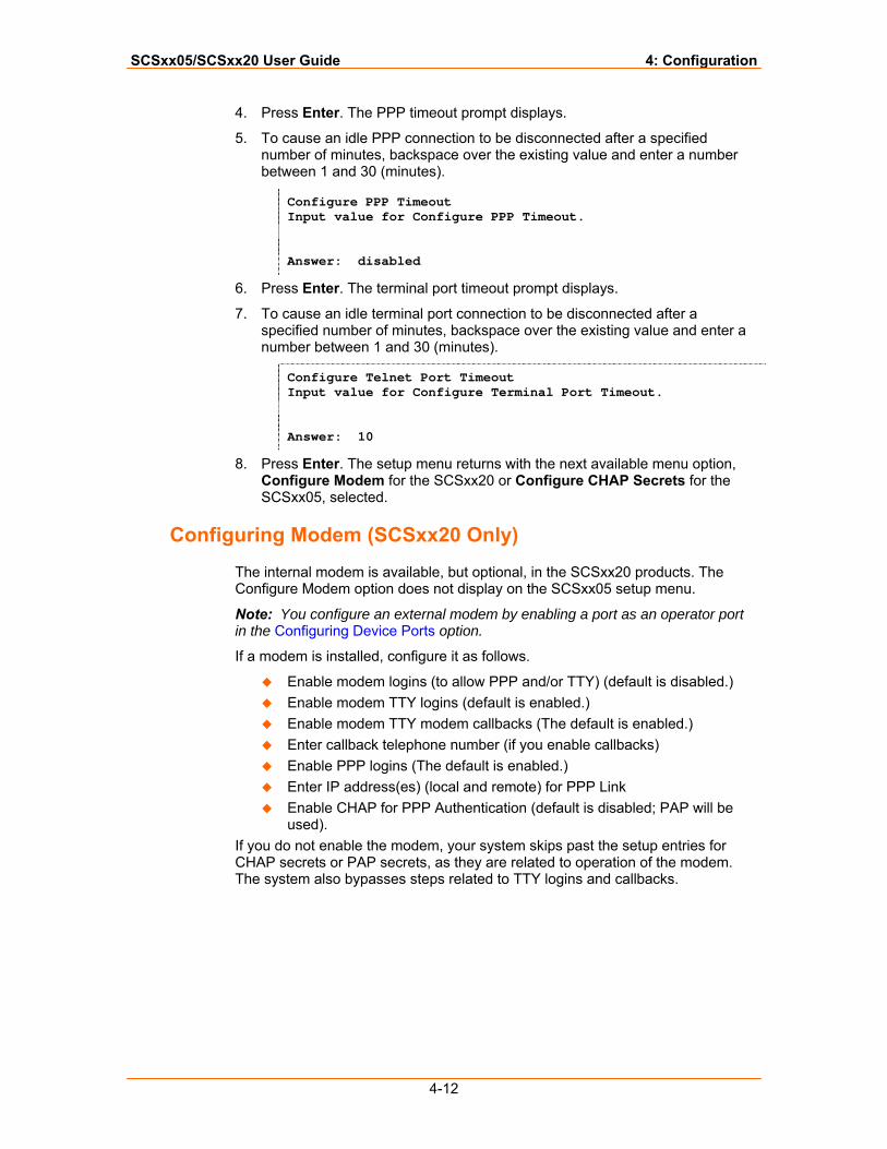
5. To cause an idle PPP connection to be disconnected after a specified number of minutes, backspace over the existing value and enter a number between 1 and 30 (minutes).
Configure PPP Timeout Input value for Configure PPP Timeout. Answer: disabled
6. Press Enter. The terminal port timeout prompt displays.
7. To cause an idle terminal port connection to be disconnected after a specified number of minutes, backspace over the existing value and enter a number between 1 and 30 (minutes).
Configure Telnet Port Timeout Input value for Configure Terminal Port Timeout. Answer: 10
8. Press Enter. The setup menu returns with the next available menu option, Configure Modem for the SCSxx20 or Configure CHAP Secrets for the SCSxx05, selected.
Configuring Modem (SCSxx20 Only)
The internal modem is available, but optional, in the SCSxx20 products. The Configure Modem option does not display on the SCSxx05 setup menu.
Note: You configure an external modem by enabling a port as an operator port in the Configuring Device Ports option.
If a modem is installed, configure it as follows.
Enable modem logins (to allow PPP and/or TTY) (default is disabled.) Enable modem TTY logins (default is enabled.) Enable modem TTY modem callbacks (The default is enabled.) Enter callback telephone number (if you enable callbacks) Enable PPP logins (The default is enabled.) Enter IP address(es) (local and remote) for PPP Link Enable CHAP for PPP Authentication (default is disabled; PAP will be
used). If you do not enable the modem, your system skips past the setup entries for CHAP secrets or PAP secrets, as they are related to operation of the modem. The system also bypasses steps related to TTY logins and callbacks.
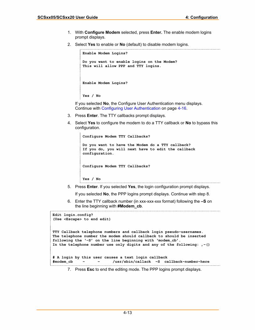
SCSxx05/SCSxx20 User Guide 4: Configuration
4-13
1. With Configure Modem selected, press Enter. The enable modem logins prompt displays.
2. Select Yes to enable or No (default) to disable modem logins.
Enable Modem Logins? Do you want to enable logins on the Modem? This will allow PPP and TTY logins. Enable Modem Logins? Yes / No
If you selected No, the Configure User Authentication menu displays. Continue with Configuring User Authentication on page 4-16.
3. Press Enter. The TTY callbacks prompt displays.
4. Select Yes to configure the modem to do a TTY callback or No to bypass this configuration.
Configure Modem TTY Callbacks? Do you want to have the Modem do a TTY callback? If you do, you will next have to edit the callback configuration. Configure Modem TTY Callbacks? Yes / No
5. Press Enter. If you selected Yes, the login configuration prompt displays.
If you selected No, the PPP logins prompt displays. Continue with step 8.
6. Enter the TTY callback number (in xxx-xxx-xxx format) following the –S on the line beginning with #Modem_cb.
Edit login.config? (Use <Escape> to end edit) TTY Callback telephone numbers and callback login pseudo-usernames. The telephone number the modem should callback to should be inserted following the ‘-S’ on the line beginning with ‘modem_cb’. In the telephone number use only digits and any of the following: ,-() # A login by this user causes a text login callback #modem_cb - - /usr/sbin/callack -S callback-number-here
7. Press Esc to end the editing mode. The PPP logins prompt displays.
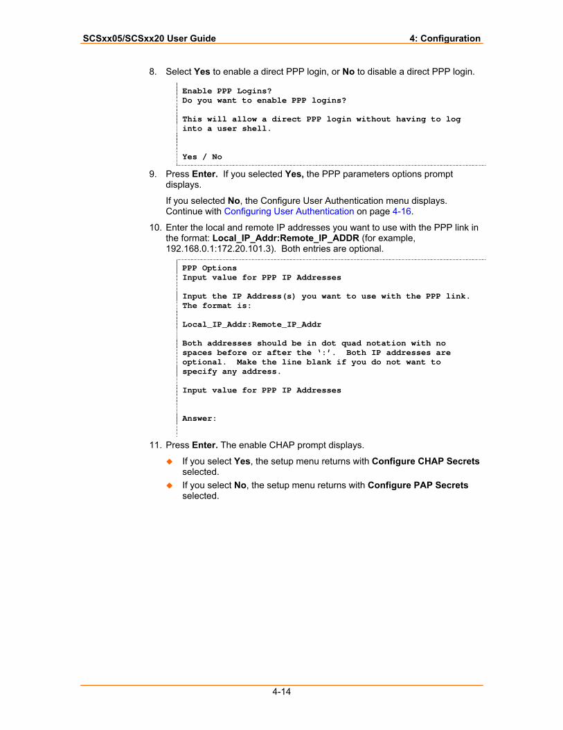
SCSxx05/SCSxx20 User Guide 4: Configuration
4-14
8. Select Yes to enable a direct PPP login, or No to disable a direct PPP login.
Enable PPP Logins? Do you want to enable PPP logins? This will allow a direct PPP login without having to log into a user shell. Yes / No
9. Press Enter. If you selected Yes, the PPP parameters options prompt displays.
If you selected No, the Configure User Authentication menu displays. Continue with Configuring User Authentication on page 4-16.
10. Enter the local and remote IP addresses you want to use with the PPP link in the format: Local_IP_Addr:Remote_IP_ADDR (for example, 192.168.0.1:172.20.101.3). Both entries are optional.
PPP Options Input value for PPP IP Addresses Input the IP Address(s) you want to use with the PPP link. The format is: Local_IP_Addr:Remote_IP_Addr Both addresses should be in dot quad notation with no spaces before or after the ‘:’. Both IP addresses are optional. Make the line blank if you do not want to specify any address. Input value for PPP IP Addresses Answer:
11. Press Enter. The enable CHAP prompt displays.
If you select Yes, the setup menu returns with Configure CHAP Secrets selected.
If you select No, the setup menu returns with Configure PAP Secrets selected.
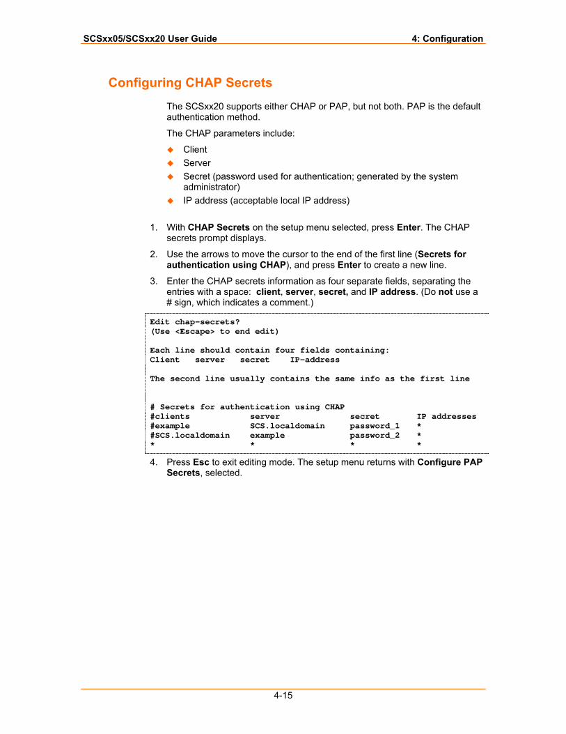
SCSxx05/SCSxx20 User Guide 4: Configuration
4-15
Configuring CHAP Secrets
The SCSxx20 supports either CHAP or PAP, but not both. PAP is the default authentication method.
The CHAP parameters include:
Client Server Secret (password used for authentication; generated by the system
administrator) IP address (acceptable local IP address)
1. With CHAP Secrets on the setup menu selected, press Enter. The CHAP
secrets prompt displays.
2. Use the arrows to move the cursor to the end of the first line (Secrets for authentication using CHAP), and press Enter to create a new line.
3. Enter the CHAP secrets information as four separate fields, separating the entries with a space: client, server, secret, and IP address. (Do not use a # sign, which indicates a comment.)
Edit chap-secrets? (Use <Escape> to end edit) Each line should contain four fields containing: Client server secret IP-address The second line usually contains the same info as the first line # Secrets for authentication using CHAP #clients server secret IP addresses #example SCS.localdomain password_1 * #SCS.localdomain example password_2 * * * * *
4. Press Esc to exit editing mode. The setup menu returns with Configure PAP Secrets, selected.
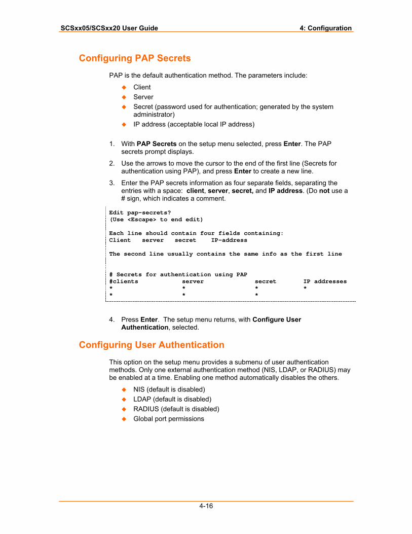
SCSxx05/SCSxx20 User Guide 4: Configuration
4-16
Configuring PAP Secrets
PAP is the default authentication method. The parameters include:
Client Server Secret (password used for authentication; generated by the system
administrator) IP address (acceptable local IP address)
1. With PAP Secrets on the setup menu selected, press Enter. The PAP
secrets prompt displays.
2. Use the arrows to move the cursor to the end of the first line (Secrets for authentication using PAP), and press Enter to create a new line.
3. Enter the PAP secrets information as four separate fields, separating the entries with a space: client, server, secret, and IP address. (Do not use a # sign, which indicates a comment.
Edit pap-secrets? (Use <Escape> to end edit) Each line should contain four fields containing: Client server secret IP-address The second line usually contains the same info as the first line # Secrets for authentication using PAP #clients server secret IP addresses * * * * * * *
4. Press Enter. The setup menu returns, with Configure User Authentication, selected.
Configuring User Authentication
This option on the setup menu provides a submenu of user authentication methods. Only one external authentication method (NIS, LDAP, or RADIUS) may be enabled at a time. Enabling one method automatically disables the others.
NIS (default is disabled) LDAP (default is disabled) RADIUS (default is disabled) Global port permissions
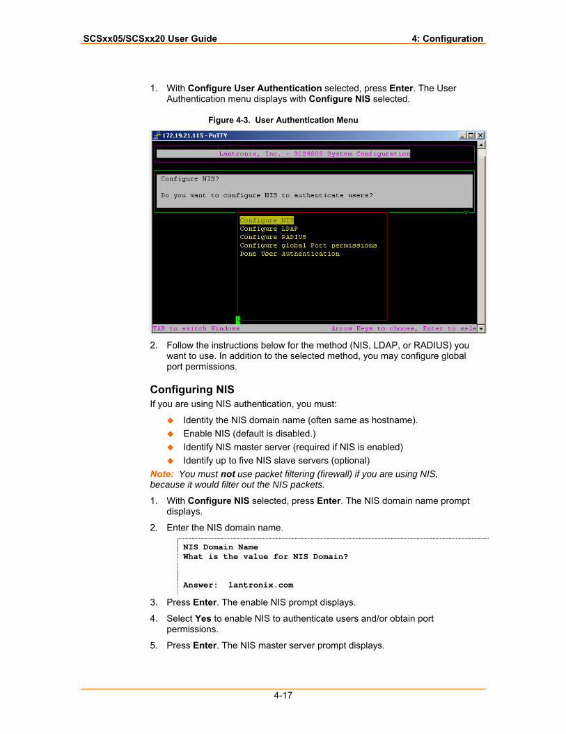
SCSxx05/SCSxx20 User Guide 4: Configuration
4-17
1. With Configure User Authentication selected, press Enter. The User Authentication menu displays with Configure NIS selected.
Figure 4-3. User Authentication Menu
2. Follow the instructions below for the method (NIS, LDAP, or RADIUS) you
want to use. In addition to the selected method, you may configure global port permissions.
Configuring NIS If you are using NIS authentication, you must:
Identity the NIS domain name (often same as hostname). Enable NIS (default is disabled.) Identify NIS master server (required if NIS is enabled) Identify up to five NIS slave servers (optional)
Note: You must not use packet filtering (firewall) if you are using NIS, because it would filter out the NIS packets.
1. With Configure NIS selected, press Enter. The NIS domain name prompt displays.
2. Enter the NIS domain name.
NIS Domain Name What is the value for NIS Domain? Answer: lantronix.com
3. Press Enter. The enable NIS prompt displays.
4. Select Yes to enable NIS to authenticate users and/or obtain port permissions.
5. Press Enter. The NIS master server prompt displays.
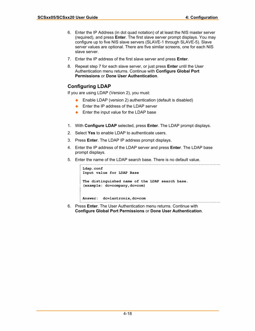
SCSxx05/SCSxx20 User Guide 4: Configuration
4-18
6. Enter the IP Address (in dot quad notation) of at least the NIS master server (required), and press Enter. The first slave server prompt displays. You may configure up to five NIS slave servers (SLAVE-1 through SLAVE-5). Slave server values are optional. There are five similar screens, one for each NIS slave server.
7. Enter the IP address of the first slave server and press Enter.
8. Repeat step 7 for each slave server, or just press Enter until the User Authentication menu returns. Continue with Configure Global Port Permissions or Done User Authentication.
Configuring LDAP If you are using LDAP (Version 2), you must:
Enable LDAP (version 2) authentication (default is disabled) Enter the IP address of the LDAP server Enter the input value for the LDAP base
1. With Configure LDAP selected, press Enter. The LDAP prompt displays.
2. Select Yes to enable LDAP to authenticate users.
3. Press Enter. The LDAP IP address prompt displays.
4. Enter the IP address of the LDAP server and press Enter. The LDAP base prompt displays.
5. Enter the name of the LDAP search base. There is no default value.
Ldap.conf Input value for LDAP Base The distinguished name of the LDAP search base. (example: dc=company,dc=com) Answer: dc=lantronix,dc=com
6. Press Enter. The User Authentication menu returns. Continue with Configure Global Port Permissions or Done User Authentication.
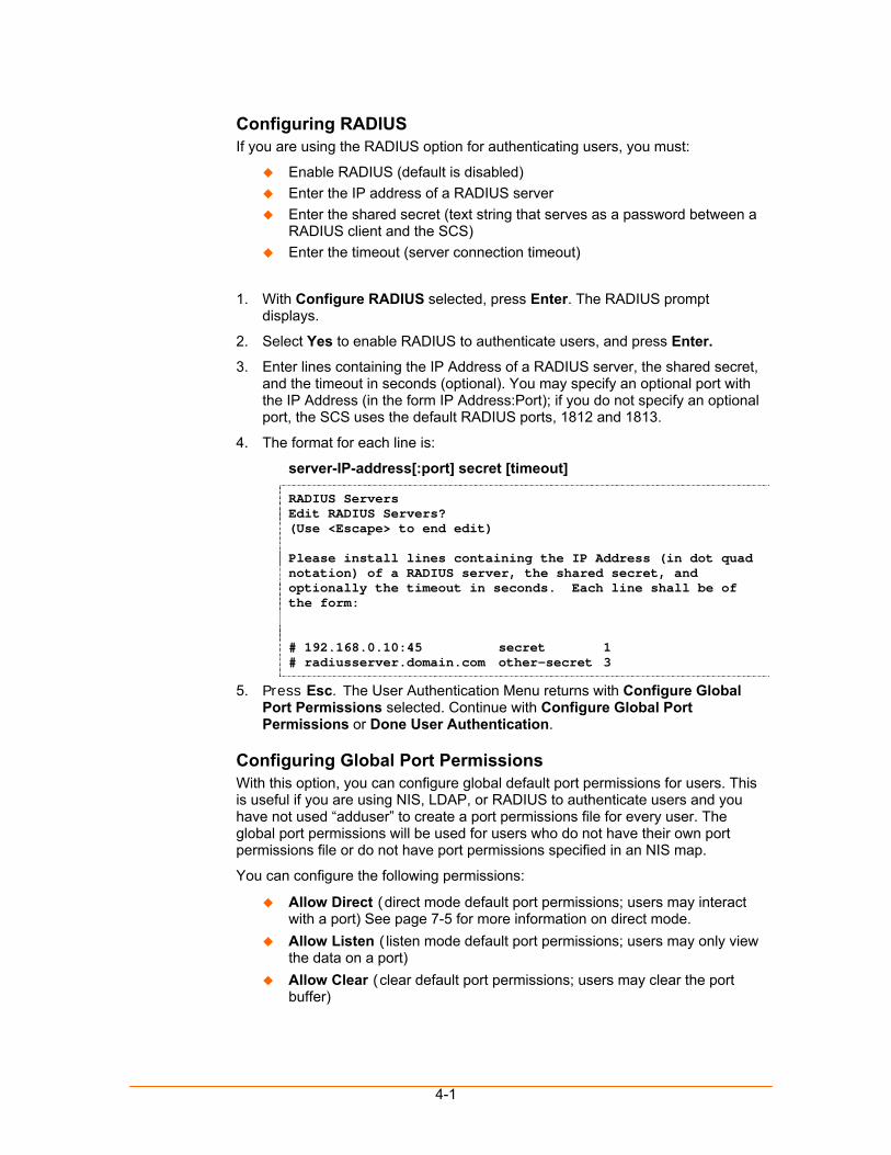
4-1
Configuring RADIUS If you are using the RADIUS option for authenticating users, you must:
Enable RADIUS (default is disabled) Enter the IP address of a RADIUS server Enter the shared secret (text string that serves as a password between a
RADIUS client and the SCS) Enter the timeout (server connection timeout)
1. With Configure RADIUS selected, press Enter. The RADIUS prompt displays.
2. Select Yes to enable RADIUS to authenticate users, and press Enter.
3. Enter lines containing the IP Address of a RADIUS server, the shared secret, and the timeout in seconds (optional). You may specify an optional port with the IP Address (in the form IP Address:Port); if you do not specify an optional port, the SCS uses the default RADIUS ports, 1812 and 1813.
4. The format for each line is:
server-IP-address[:port] secret [timeout]
RADIUS Servers Edit RADIUS Servers? (Use <Escape> to end edit) Please install lines containing the IP Address (in dot quad notation) of a RADIUS server, the shared secret, and optionally the timeout in seconds. Each line shall be of the form: # 192.168.0.10:45 secret 1 # radiusserver.domain.com other-secret 3
5. Press Esc. The User Authentication Menu returns with Configure Global Port Permissions selected. Continue with Configure Global Port Permissions or Done User Authentication.
Configuring Global Port Permissions With this option, you can configure global default port permissions for users. This is useful if you are using NIS, LDAP, or RADIUS to authenticate users and you have not used “adduser” to create a port permissions file for every user. The global port permissions will be used for users who do not have their own port permissions file or do not have port permissions specified in an NIS map.
You can configure the following permissions:
Allow Direct (direct mode default port permissions; users may interact with a port) See page 7-5 for more information on direct mode.
Allow Listen (listen mode default port permissions; users may only view the data on a port)
Allow Clear (clear default port permissions; users may clear the port buffer)
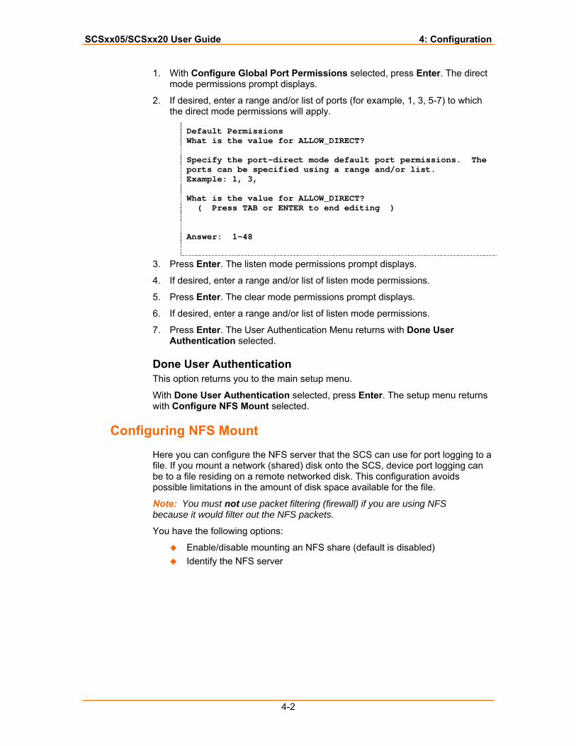
SCSxx05/SCSxx20 User Guide 4: Configuration
4-2
1. With Configure Global Port Permissions selected, press Enter. The direct mode permissions prompt displays.
2. If desired, enter a range and/or list of ports (for example, 1, 3, 5-7) to which the direct mode permissions will apply.
Default Permissions What is the value for ALLOW_DIRECT? Specify the port-direct mode default port permissions. The ports can be specified using a range and/or list. Example: 1, 3, What is the value for ALLOW_DIRECT? ( Press TAB or ENTER to end editing ) Answer: 1-48
3. Press Enter. The listen mode permissions prompt displays.
4. If desired, enter a range and/or list of listen mode permissions.
5. Press Enter. The clear mode permissions prompt displays.
6. If desired, enter a range and/or list of listen mode permissions.
7. Press Enter. The User Authentication Menu returns with Done User Authentication selected.
Done User Authentication This option returns you to the main setup menu.
With Done User Authentication selected, press Enter. The setup menu returns with Configure NFS Mount selected.
Configuring NFS Mount
Here you can configure the NFS server that the SCS can use for port logging to a file. If you mount a network (shared) disk onto the SCS, device port logging can be to a file residing on a remote networked disk. This configuration avoids possible limitations in the amount of disk space available for the file.
Note: You must not use packet filtering (firewall) if you are using NFS because it would filter out the NFS packets.
You have the following options:
Enable/disable mounting an NFS share (default is disabled) Identify the NFS server
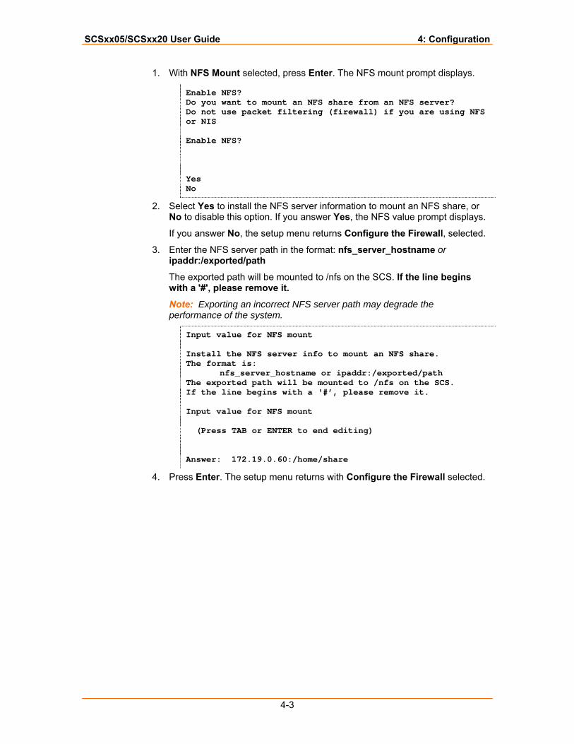
SCSxx05/SCSxx20 User Guide 4: Configuration
4-3
1. With NFS Mount selected, press Enter. The NFS mount prompt displays.
Enable NFS? Do you want to mount an NFS share from an NFS server? Do not use packet filtering (firewall) if you are using NFS or NIS Enable NFS? Yes No
2. Select Yes to install the NFS server information to mount an NFS share, or No to disable this option. If you answer Yes, the NFS value prompt displays.
If you answer No, the setup menu returns Configure the Firewall, selected.
3. Enter the NFS server path in the format: nfs_server_hostname or ipaddr:/exported/path
The exported path will be mounted to /nfs on the SCS. If the line begins with a '#', please remove it.
Note: Exporting an incorrect NFS server path may degrade the performance of the system.
Input value for NFS mount Install the NFS server info to mount an NFS share. The format is: nfs_server_hostname or ipaddr:/exported/path The exported path will be mounted to /nfs on the SCS. If the line begins with a ‘#’, please remove it. Input value for NFS mount (Press TAB or ENTER to end editing) Answer: 172.19.0.60:/home/share
4. Press Enter. The setup menu returns with Configure the Firewall selected.
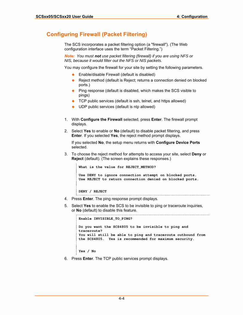
SCSxx05/SCSxx20 User Guide 4: Configuration
4-4
Configuring Firewall (Packet Filtering)
The SCS incorporates a packet filtering option (a "firewall"). (The Web configuration interface uses the term “Packet Filtering.”)
Note: You must not use packet filtering (firewall) if you are using NFS or NIS, because it would filter out the NFS or NIS packets.
You may configure the firewall for your site by setting the following parameters.
Enable/disable Firewall (default is disabled) Reject method (default is Reject; returns a connection denied on blocked
ports.) Ping response (default is disabled, which makes the SCS visible to
pings) TCP public services (default is ssh, telnet, and https allowed) UDP public services (default is ntp allowed)
1. With Configure the Firewall selected, press Enter. The firewall prompt displays.
2. Select Yes to enable or No (default) to disable packet filtering, and press Enter. If you selected Yes, the reject method prompt displays.
If you selected No, the setup menu returns with Configure Device Ports selected.
3. To choose the reject method for attempts to access your site, select Deny or Reject (default). (The screen explains these responses.)
What is the value for REJECT_METHOD? Use DENY to ignore connection attempt on blocked ports. Use REJECT to return connection denied on blocked ports. DENY / REJECT
4. Press Enter. The ping response prompt displays.
5. Select Yes to enable the SCS to be invisible to ping or traceroute inquiries, or No (default) to disable this feature.
Enable INVISIBLE_TO_PING? Do you want the SCS4805 to be invisible to ping and traceroute? You will still be able to ping and traceroute outbound from the SCS4805. Yes is recommended for maximum security. Yes / No
6. Press Enter. The TCP public services prompt displays.
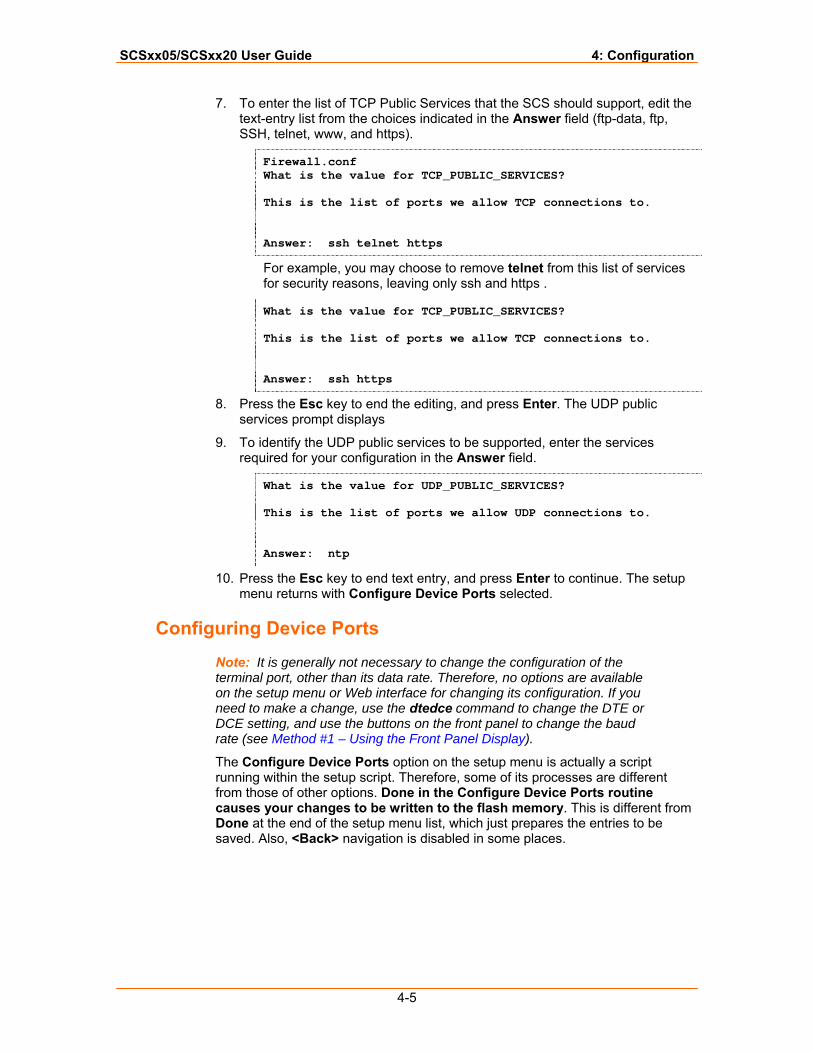
SCSxx05/SCSxx20 User Guide 4: Configuration
4-5
7. To enter the list of TCP Public Services that the SCS should support, edit the text-entry list from the choices indicated in the Answer field (ftp-data, ftp, SSH, telnet, www, and https).
Firewall.conf What is the value for TCP_PUBLIC_SERVICES? This is the list of ports we allow TCP connections to. Answer: ssh telnet https
For example, you may choose to remove telnet from this list of services for security reasons, leaving only ssh and https .
What is the value for TCP_PUBLIC_SERVICES? This is the list of ports we allow TCP connections to. Answer: ssh https
8. Press the Esc key to end the editing, and press Enter. The UDP public services prompt displays
9. To identify the UDP public services to be supported, enter the services required for your configuration in the Answer field.
What is the value for UDP_PUBLIC_SERVICES? This is the list of ports we allow UDP connections to. Answer: ntp
10. Press the Esc key to end text entry, and press Enter to continue. The setup menu returns with Configure Device Ports selected.
Configuring Device Ports
Note: It is generally not necessary to change the configuration of the terminal port, other than its data rate. Therefore, no options are available on the setup menu or Web interface for changing its configuration. If you need to make a change, use the dtedce command to change the DTE or DCE setting, and use the buttons on the front panel to change the baud rate (see Method #1 – Using the Front Panel Display).
The Configure Device Ports option on the setup menu is actually a script running within the setup script. Therefore, some of its processes are different from those of other options. Done in the Configure Device Ports routine causes your changes to be written to the flash memory. This is different from Done at the end of the setup menu list, which just prepares the entries to be saved. Also, <Back> navigation is disabled in some places.
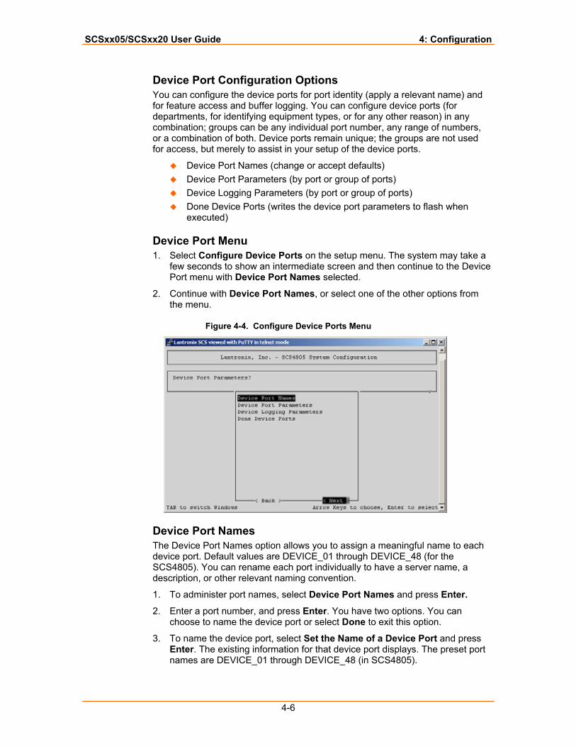
SCSxx05/SCSxx20 User Guide 4: Configuration
4-6
Device Port Configuration Options You can configure the device ports for port identity (apply a relevant name) and for feature access and buffer logging. You can configure device ports (for departments, for identifying equipment types, or for any other reason) in any combination; groups can be any individual port number, any range of numbers, or a combination of both. Device ports remain unique; the groups are not used for access, but merely to assist in your setup of the device ports.
Device Port Names (change or accept defaults) Device Port Parameters (by port or group of ports) Device Logging Parameters (by port or group of ports) Done Device Ports (writes the device port parameters to flash when
executed)
Device Port Menu 1. Select Configure Device Ports on the setup menu. The system may take a
few seconds to show an intermediate screen and then continue to the Device Port menu with Device Port Names selected.
2. Continue with Device Port Names, or select one of the other options from the menu.
Figure 4-4. Configure Device Ports Menu
Device Port Names The Device Port Names option allows you to assign a meaningful name to each device port. Default values are DEVICE_01 through DEVICE_48 (for the SCS4805). You can rename each port individually to have a server name, a description, or other relevant naming convention.
1. To administer port names, select Device Port Names and press Enter.
2. Enter a port number, and press Enter. You have two options. You can choose to name the device port or select Done to exit this option.
3. To name the device port, select Set the Name of a Device Port and press Enter. The existing information for that device port displays. The preset port names are DEVICE_01 through DEVICE_48 (in SCS4805).
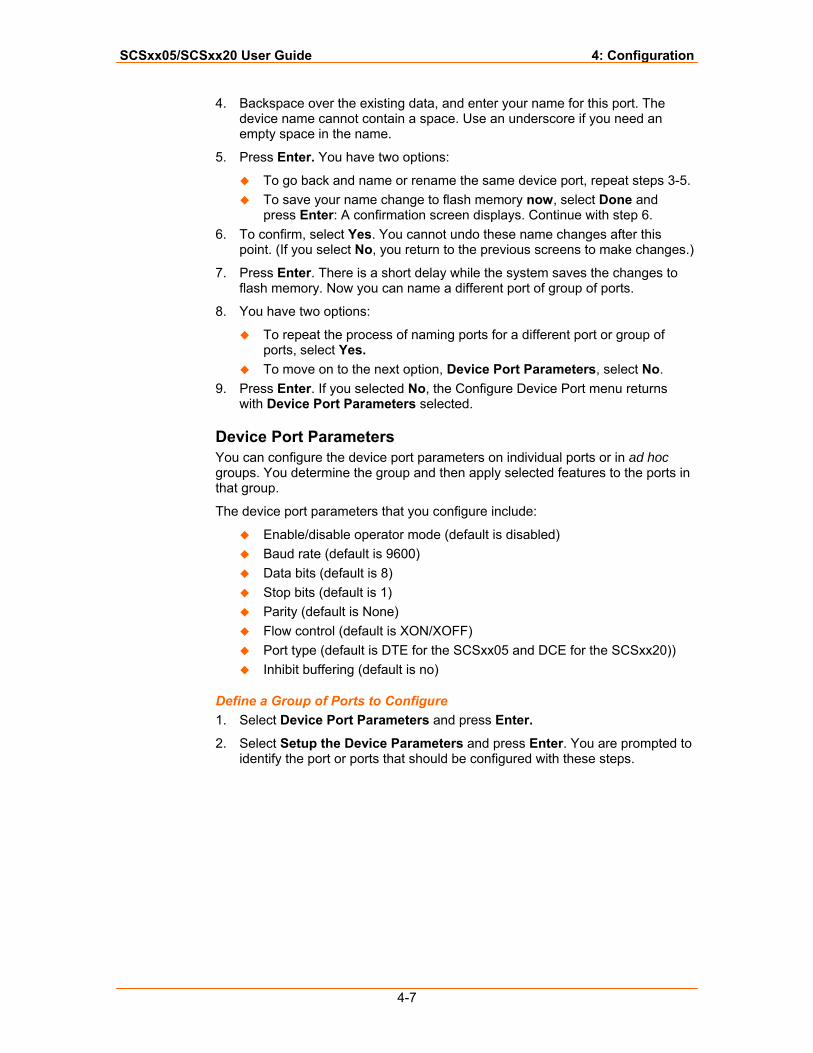
SCSxx05/SCSxx20 User Guide 4: Configuration
4-7
4. Backspace over the existing data, and enter your name for this port. The device name cannot contain a space. Use an underscore if you need an empty space in the name.
5. Press Enter. You have two options:
To go back and name or rename the same device port, repeat steps 3-5. To save your name change to flash memory now, select Done and
press Enter: A confirmation screen displays. Continue with step 6. 6. To confirm, select Yes. You cannot undo these name changes after this
point. (If you select No, you return to the previous screens to make changes.)
7. Press Enter. There is a short delay while the system saves the changes to flash memory. Now you can name a different port of group of ports.
8. You have two options:
To repeat the process of naming ports for a different port or group of ports, select Yes.
To move on to the next option, Device Port Parameters, select No. 9. Press Enter. If you selected No, the Configure Device Port menu returns
with Device Port Parameters selected.
Device Port Parameters You can configure the device port parameters on individual ports or in ad hoc groups. You determine the group and then apply selected features to the ports in that group.
The device port parameters that you configure include:
Enable/disable operator mode (default is disabled) Baud rate (default is 9600) Data bits (default is 8) Stop bits (default is 1) Parity (default is None) Flow control (default is XON/XOFF) Port type (default is DTE for the SCSxx05 and DCE for the SCSxx20)) Inhibit buffering (default is no)
Define a Group of Ports to Configure 1. Select Device Port Parameters and press Enter.
2. Select Setup the Device Parameters and press Enter. You are prompted to identify the port or ports that should be configured with these steps.

SCSxx05/SCSxx20 User Guide 4: Configuration
4-8
3. In the Answer field, enter the number, range, or combination of ports to be administered.
What device port do you want to configure? Input a device number, a device name, or a range. Examples of ranges: 3,7,9 2-12 1,4,6-9,14 Valid port range is 1-48 What device port do you want to configure? Answer: 1-3,5,7-9,26
4. Press Enter. The enable operator port prompt displays. This option allows PPP as well as terminal logins through an external modem.
Note: If you connect a modem, make sure to set the port type to DTE.
Enable Port 3,7,9 as an operator port? Do you want to enable system logins on Port 3,7,9? A modem may be connected to this port and PPP will be supported as well as TTT logins. If you connect a modem to this port, make sure the port type is set to DTE. Enable Port 3,7,9 as an operator port? Yes / No
5. Select Yes to enable system logins, or No (default) to disable system logins, and press Enter. The operator port baud rate displays if you enabled an operator port or group of ports; otherwise the baud rate prompt displays.
Operator Port Baud Rate You can select from seven device baud rates: 2400, 4800, 9600, 19200, 38400, 57600 and 115,200. The default is 115,200.
1. Use the arrow keys to select the baud rate for the operator port(s) from the list displayed.
2. Press Enter. The baud rate prompt displays.
Baud Rate You can select from seven device baud rates: 2400, 4800, 9600, 19200, 38400, 57600 and 115,200. Most devices use 9600 as the terminal/administration port's baud rate, so the device port defaults to this value. Check the equipment settings and documentation for the proper baud rate.
1. Use the arrow keys to select the baud rate for the port(s) from the list displayed.
2. Press Enter. The data bits prompt displays.
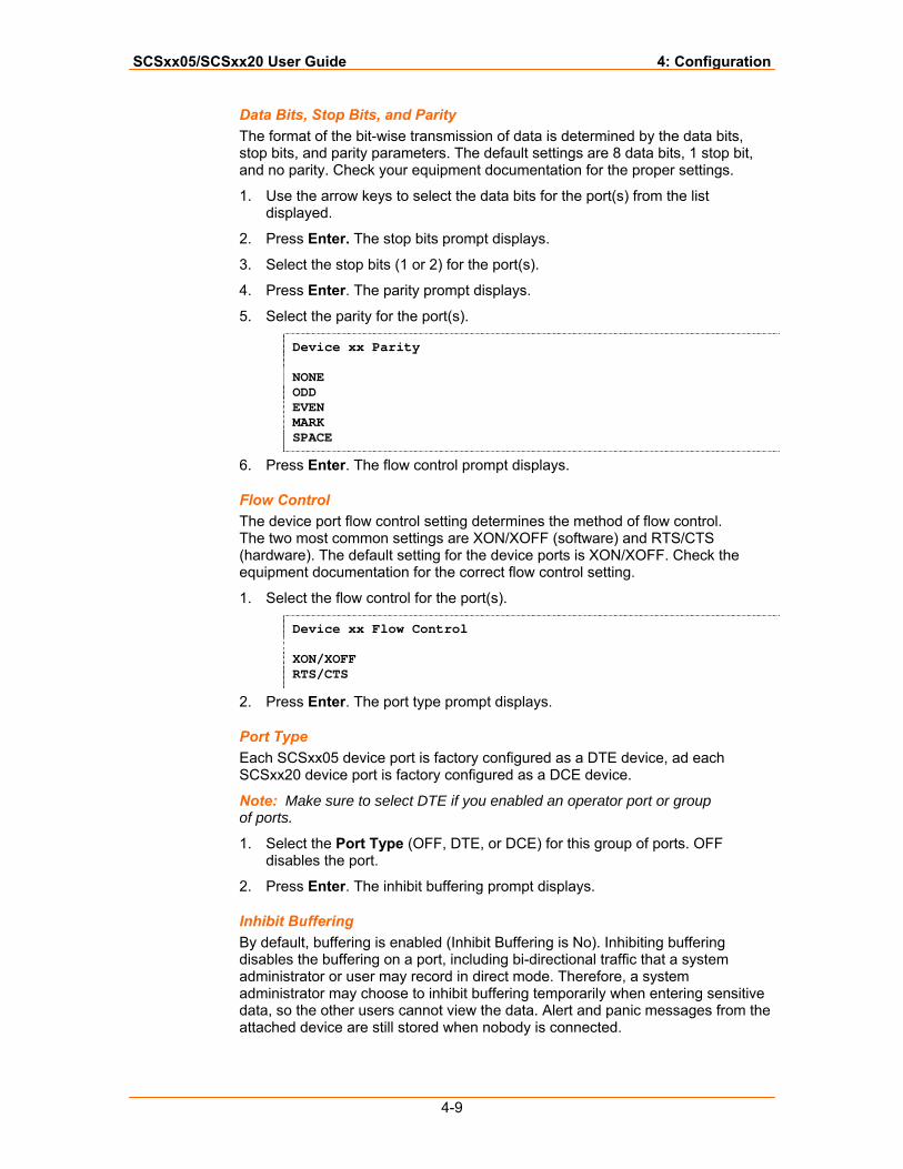
SCSxx05/SCSxx20 User Guide 4: Configuration
4-9
Data Bits, Stop Bits, and Parity The format of the bit-wise transmission of data is determined by the data bits, stop bits, and parity parameters. The default settings are 8 data bits, 1 stop bit, and no parity. Check your equipment documentation for the proper settings.
1. Use the arrow keys to select the data bits for the port(s) from the list displayed.
2. Press Enter. The stop bits prompt displays.
3. Select the stop bits (1 or 2) for the port(s).
4. Press Enter. The parity prompt displays.
5. Select the parity for the port(s).
Device xx Parity NONE ODD EVEN MARK SPACE
6. Press Enter. The flow control prompt displays.
Flow Control The device port flow control setting determines the method of flow control. The two most common settings are XON/XOFF (software) and RTS/CTS (hardware). The default setting for the device ports is XON/XOFF. Check the equipment documentation for the correct flow control setting.
1. Select the flow control for the port(s).
Device xx Flow Control XON/XOFF RTS/CTS
2. Press Enter. The port type prompt displays.
Port Type Each SCSxx05 device port is factory configured as a DTE device, ad each SCSxx20 device port is factory configured as a DCE device.
Note: Make sure to select DTE if you enabled an operator port or group of ports.
1. Select the Port Type (OFF, DTE, or DCE) for this group of ports. OFF disables the port.
2. Press Enter. The inhibit buffering prompt displays.
Inhibit Buffering By default, buffering is enabled (Inhibit Buffering is No). Inhibiting buffering disables the buffering on a port, including bi-directional traffic that a system administrator or user may record in direct mode. Therefore, a system administrator may choose to inhibit buffering temporarily when entering sensitive data, so the other users cannot view the data. Alert and panic messages from the attached device are still stored when nobody is connected.
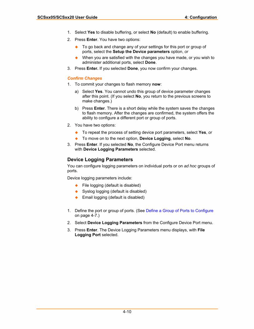
SCSxx05/SCSxx20 User Guide 4: Configuration
4-10
1. Select Yes to disable buffering, or select No (default) to enable buffering.
2. Press Enter. You have two options:
To go back and change any of your settings for this port or group of ports, select the Setup the Device parameters option, or
When you are satisfied with the changes you have made, or you wish to administer additional ports, select Done.
3. Press Enter. If you selected Done, you now confirm your changes.
Confirm Changes 1. To commit your changes to flash memory now:
a) Select Yes. You cannot undo this group of device parameter changes after this point. (If you select No, you return to the previous screens to make changes.)
b) Press Enter. There is a short delay while the system saves the changes to flash memory. After the changes are confirmed, the system offers the ability to configure a different port or group of ports.
2. You have two options:
To repeat the process of setting device port parameters, select Yes, or To move on to the next option, Device Logging, select No.
3. Press Enter. If you selected No, the Configure Device Port menu returns with Device Logging Parameters selected.
Device Logging Parameters You can configure logging parameters on individual ports or on ad hoc groups of ports.
Device logging parameters include:
File logging (default is disabled) Syslog logging (default is disabled) Email logging (default is disabled)
1. Define the port or group of ports. (See Define a Group of Ports to Configure on page 4-7.)
2. Select Device Logging Parameters from the Configure Device Port menu.
3. Press Enter. The Device Logging Parameters menu displays, with File Logging Port selected.
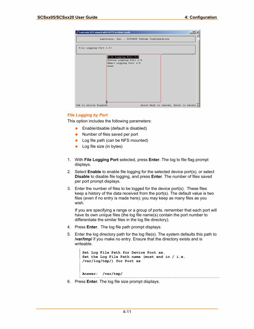
SCSxx05/SCSxx20 User Guide 4: Configuration
4-11
File Logging by Port This option includes the following parameters:
Enable/disable (default is disabled) Number of files saved per port Log file path (can be NFS mounted) Log file size (in bytes)
1. With File Logging Port selected, press Enter. The log to file flag prompt displays.
2. Select Enable to enable file logging for the selected device port(s), or select Disable to disable file logging, and press Enter. The number of files saved per port prompt displays.
3. Enter the number of files to be logged for the device port(s). These files keep a history of the data received from the port(s). The default value is two files (even if no entry is made here); you may keep as many files as you wish.
If you are specifying a range or a group of ports, remember that each port will have its own unique files (the log file name(s) contain the port number to differentiate the similar files in the log file directory).
4. Press Enter. The log file path prompt displays.
5. Enter the log directory path for the log file(s). The system defaults this path to /var/tmp/ if you make no entry. Ensure that the directory exists and is writeable.
Set Log File Path for Device Port xx. Set the Log File Path name (must end in / i.e. /var/log/tmp/) for Port xx Answer: /var/tmp/
6. Press Enter. The log file size prompt displays.
SCSxx05/SCSxx20 User Guide 4: Configuration
4-12
7. Enter the desired log file size in bytes (2048 = 2K). The default is 2048 bytes. The amount of available memory limits the maximum size of the log file.
8. Press Enter. the Device Logging Parameters menu returns with Syslog Port Logging, selected.
Syslog Logging by Port Next, you configure the following syslog options for the same port(s):
Enable/Disable (default is disabled) Set Syslog Facility (user, local0, local1, local2, etc....local7) Set Syslog Level (Emergency, Alert, Critical, Error, Warning, Notice, Info,
Debug)
1. With Syslog Port Logging selected, press Enter. The syslog flag prompt displays.
2. Select to Enable or Disable (default) syslogging for the port(s), and press Enter. The syslog facility prompt displays.
3. From the list, select the syslog facility to use for the port(s) and press Enter. The set syslog level prompt displays.
4. From the list, select the syslog alert level for the port(s). The levels are, from the top down, most severe to least severe. They classify the importance of each connected server within your configuration.
5. Press Enter. The Device Logging Parameters menu returns with Email Logging Port selected.
Email Logging Email Logging (Email Notification) sends an email message to pre-defined email addresses when 'alert' criteria have been met. Data received on the SCS device port(s) trigger the alert. The default is disabled, although some preset values are entered for the timers.
Email logging provides the following options for a port or group of ports:
Enable/disable (default is disabled) Alarm byte count (count the number of characters to trigger an alarm) Alarm timer (how long to capture data after byte count trigger) Alarm ignore timer (how long, after byte count trigger, to ignore additional
alarms) Email subject line (put in a message header to be read in the email
subject) “Send To” email address “cc:” to email address
1. With Email Logging Port selected, press Enter. The email flag prompt displays.
2. Select Enable or Disable (default). If enabled, the email flag triggers an email message to be sent to the defined recipients when the alert condition has been met. Press Enter. The alarm byte counter prompt displays.
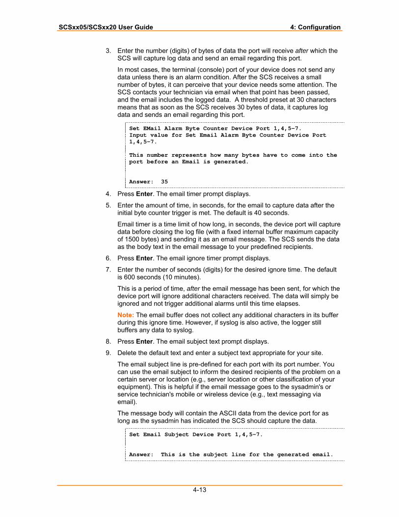
SCSxx05/SCSxx20 User Guide 4: Configuration
4-13
3. Enter the number (digits) of bytes of data the port will receive after which the SCS will capture log data and send an email regarding this port.
In most cases, the terminal (console) port of your device does not send any data unless there is an alarm condition. After the SCS receives a small number of bytes, it can perceive that your device needs some attention. The SCS contacts your technician via email when that point has been passed, and the email includes the logged data. A threshold preset at 30 characters means that as soon as the SCS receives 30 bytes of data, it captures log data and sends an email regarding this port.
Set EMail Alarm Byte Counter Device Port 1,4,5-7. Input value for Set Email Alarm Byte Counter Device Port 1,4,5-7. This number represents how many bytes have to come into the port before an Email is generated. Answer: 35
4. Press Enter. The email timer prompt displays.
5. Enter the amount of time, in seconds, for the email to capture data after the initial byte counter trigger is met. The default is 40 seconds.
Email timer is a time limit of how long, in seconds, the device port will capture data before closing the log file (with a fixed internal buffer maximum capacity of 1500 bytes) and sending it as an email message. The SCS sends the data as the body text in the email message to your predefined recipients.
6. Press Enter. The email ignore timer prompt displays.
7. Enter the number of seconds (digits) for the desired ignore time. The default is 600 seconds (10 minutes).
This is a period of time, after the email message has been sent, for which the device port will ignore additional characters received. The data will simply be ignored and not trigger additional alarms until this time elapses.
Note: The email buffer does not collect any additional characters in its buffer during this ignore time. However, if syslog is also active, the logger still buffers any data to syslog.
8. Press Enter. The email subject text prompt displays.
9. Delete the default text and enter a subject text appropriate for your site.
The email subject line is pre-defined for each port with its port number. You can use the email subject to inform the desired recipients of the problem on a certain server or location (e.g., server location or other classification of your equipment). This is helpful if the email message goes to the sysadmin's or service technician's mobile or wireless device (e.g., text messaging via email).
The message body will contain the ASCII data from the device port for as long as the sysadmin has indicated the SCS should capture the data.
Set Email Subject Device Port 1,4,5-7. Answer: This is the subject line for the generated email.
SCSxx05/SCSxx20 User Guide 4: Configuration
4-14
10. Press Enter. The email address prompt displays.
11. Enter the complete email address of the message recipient(s) for each device port(s). Each device port has its own recipient list. If you wish to enter more than one email address, separate the addresses with a single space.
Set Email Address(es) Device Port 1,4,5-7. Answer: [email protected]
12. Press Enter. The cc: prompt displays.
13. Enter the email address(es), if any, to which the alert message should be copied. If entering more than one email address, separate the addresses with a single space. You may cc: as many parties as you wish.
14. Press Enter. The Device Logging Parameters menu returns with Done selected. You may select the other options to change you settings, if desired.
15. When you are satisfied with your entries and want to save them, press Enter. A confirmation prompt displays:
16. To confirm your entries, select Yes. The system saves the entries to flash memory. You have two options:
To configure additional device ports, select Yes and press Enter. If you have finished configuring device ports, select No and press Enter.
The Device Logging Parameters menu returns with Done Device Ports selected. Note: Email notification changes do not take affect until after the system reboots.
Done Device Ports To return to the setup menu when you are satisfied with your device port settings:
1. Select Done Device Ports.
2. Press Enter. The setup menu displays with Software Updates selected.
Updating Software
Use this option to download the latest firmware for your SCS. You must have an ftp server set up on your network to perform these actions. You will need to enter:
Server type: ftp or tftp (tftp is the default) IP address of the server FTP or TFTP path FTP user FTP password of the user Software update files (default is none)
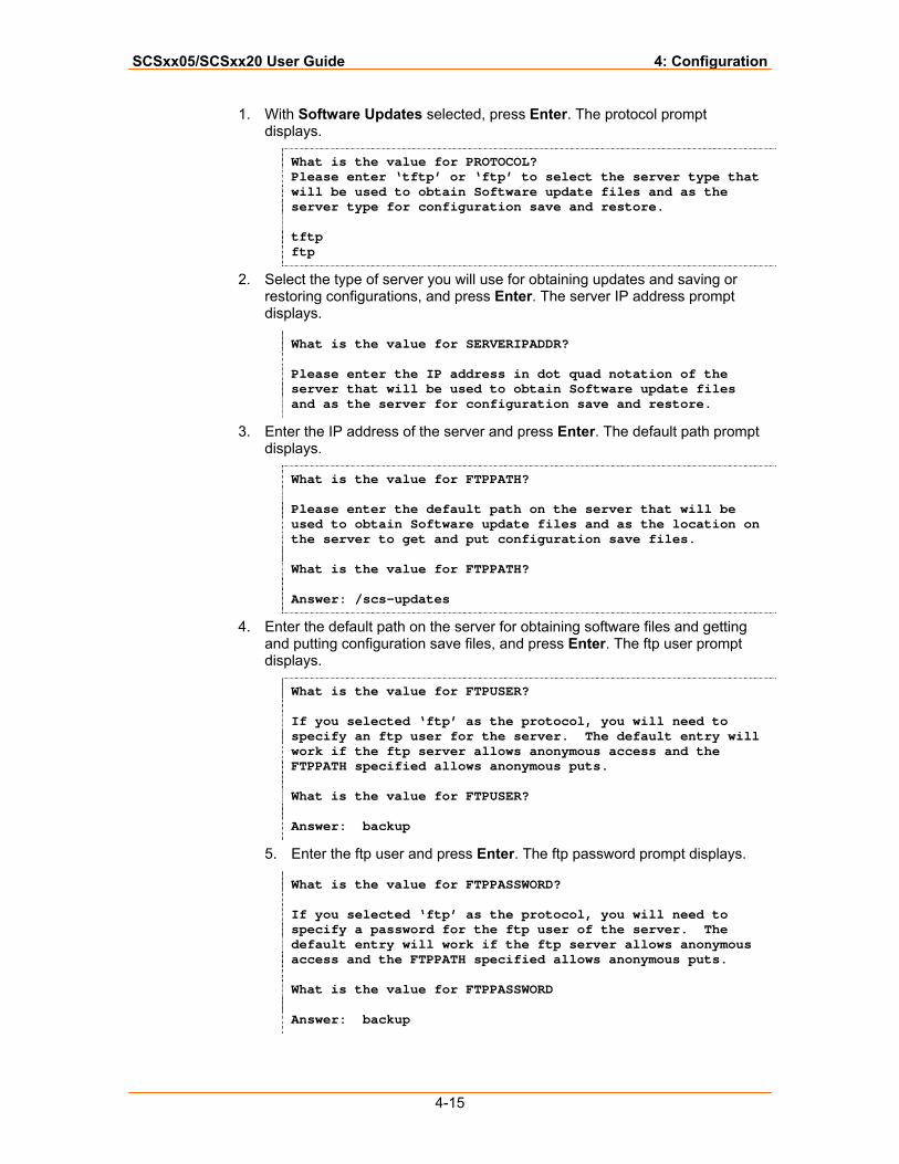
SCSxx05/SCSxx20 User Guide 4: Configuration
4-15
1. With Software Updates selected, press Enter. The protocol prompt displays.
What is the value for PROTOCOL? Please enter ‘tftp’ or ‘ftp’ to select the server type that will be used to obtain Software update files and as the server type for configuration save and restore. tftp ftp
2. Select the type of server you will use for obtaining updates and saving or restoring configurations, and press Enter. The server IP address prompt displays.
What is the value for SERVERIPADDR? Please enter the IP address in dot quad notation of the server that will be used to obtain Software update files and as the server for configuration save and restore.
3. Enter the IP address of the server and press Enter. The default path prompt displays.
What is the value for FTPPATH? Please enter the default path on the server that will be used to obtain Software update files and as the location on the server to get and put configuration save files. What is the value for FTPPATH? Answer: /scs-updates
4. Enter the default path on the server for obtaining software files and getting and putting configuration save files, and press Enter. The ftp user prompt displays.
What is the value for FTPUSER? If you selected ‘ftp’ as the protocol, you will need to specify an ftp user for the server. The default entry will work if the ftp server allows anonymous access and the FTPPATH specified allows anonymous puts. What is the value for FTPUSER? Answer: backup
5. Enter the ftp user and press Enter. The ftp password prompt displays.
What is the value for FTPPASSWORD? If you selected ‘ftp’ as the protocol, you will need to specify a password for the ftp user of the server. The default entry will work if the ftp server allows anonymous access and the FTPPATH specified allows anonymous puts. What is the value for FTPPASSWORD Answer: backup
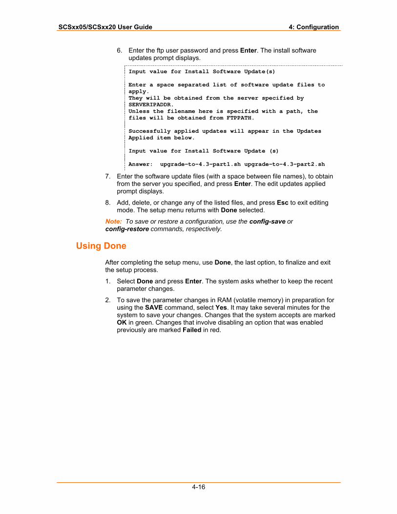
SCSxx05/SCSxx20 User Guide 4: Configuration
4-16
6. Enter the ftp user password and press Enter. The install software updates prompt displays.
Input value for Install Software Update(s) Enter a space separated list of software update files to apply. They will be obtained from the server specified by SERVERIPADDR. Unless the filename here is specified with a path, the files will be obtained from FTPPATH. Successfully applied updates will appear in the Updates Applied item below. Input value for Install Software Update (s) Answer: upgrade-to-4.3-part1.sh upgrade-to-4.3-part2.sh
7. Enter the software update files (with a space between file names), to obtain from the server you specified, and press Enter. The edit updates applied prompt displays.
8. Add, delete, or change any of the listed files, and press Esc to exit editing mode. The setup menu returns with Done selected.
Note: To save or restore a configuration, use the config-save or config-restore commands, respectively.
Using Done
After completing the setup menu, use Done, the last option, to finalize and exit the setup process.
1. Select Done and press Enter. The system asks whether to keep the recent parameter changes.
2. To save the parameter changes in RAM (volatile memory) in preparation for using the SAVE command, select Yes. It may take several minutes for the system to save your changes. Changes that the system accepts are marked OK in green. Changes that involve disabling an option that was enabled previously are marked Failed in red.
SCSxx05/SCSxx20 User Guide 4: Configuration
4-17
Saving
This SAVE command saves all changes and updates to non-volatile memory.
The SCS automatically saves the programmed parameters after running the setup script for the first time only. After that, the system administrator must run SAVE manually, as follows:
1. To permanently save any parameter changes, type SAVE (all caps) at the command prompt.
2. Press Enter. It may take a few minutes for the system to save your entries.
The reboot and the poweroff commands check for unsaved data before execution, just in case a SAVE is required. They prompt you to execute a SAVE, if necessary.
Note: SAVE does not store the buffered data, which is only maintained in RAM. If you require the buffered data, you can poll the appropriate ports and capture the buffered data at any time.
Rebooting
The very first time you log in to the SCS as sysadmin, a special routine runs to properly set up the system files, read/write operations, and other aspects of the file system. The SCS automatically reboots after running the setup script for the first time. All other setup script sessions require you to use the reboot command to ensure that all configuration changes are made.
1. To make the parameter changes take effect, type reboot at the command prompt.
2. Press Enter.
3. If file changes have not been saved into non-volatile memory, the reboot operation includes a prompt, allowing you to SAVE the files if desired.
Note: The system administrator is automatically logged out.
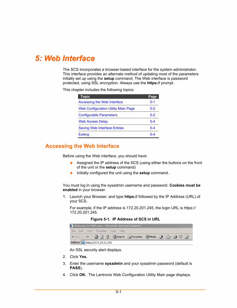
5-1
55:: WWeebb IInntteerrffaaccee The SCS incorporates a browser-based interface for the system administrator. This interface provides an alternate method of updating most of the parameters initially set up using the setup command. The Web interface is password protected, using SSL encryption. Always use the https:// prompt.
This chapter includes the following topics:
Topic Page Accessing the Web Interface 5-1
Web Configuration Utility Main Page 5-2
Configurable Parameters 5-2
Web Access Delay 5-4
Saving Web Interface Entries 5-4
Exiting 5-4
Accessing the Web Interface
Before using the Web interface, you should have:
Assigned the IP address of the SCS (using either the buttons on the front of the unit or the setup command)
Initially configured the unit using the setup command.
You must log in using the sysadmin username and password. Cookies must be enabled in your browser.
1. Launch your Browser, and type https:// followed by the IP Address (URL) of your SCS.
For example, if the IP address is 172.20.201.245, the login URL is https:// 172.20.201.245.
Figure 5-1. IP Address of SCS in URL
An SSL security alert displays.
2. Click Yes.
3. Enter the username sysadmin and your sysadmin password (default is PASS).
4. Click OK. The Lantronix Web Configuration Utility Main page displays.
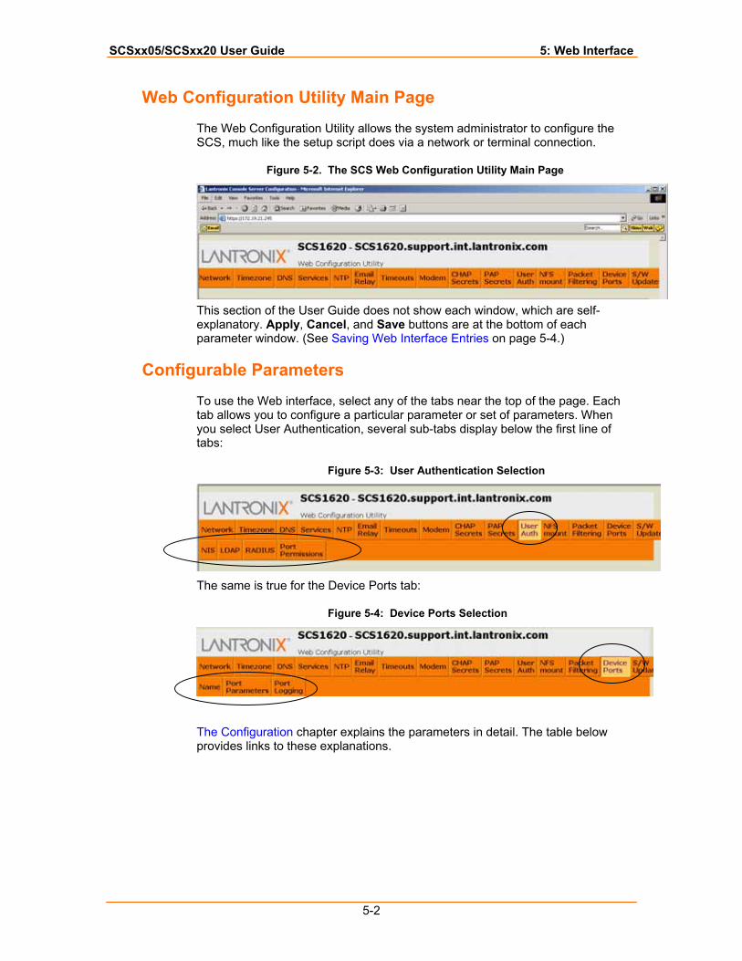
SCSxx05/SCSxx20 User Guide 5: Web Interface
5-2
Web Configuration Utility Main Page
The Web Configuration Utility allows the system administrator to configure the SCS, much like the setup script does via a network or terminal connection.
Figure 5-2. The SCS Web Configuration Utility Main Page
This section of the User Guide does not show each window, which are self-explanatory. Apply, Cancel, and Save buttons are at the bottom of each parameter window. (See Saving Web Interface Entries on page 5-4.)
Configurable Parameters
To use the Web interface, select any of the tabs near the top of the page. Each tab allows you to configure a particular parameter or set of parameters. When you select User Authentication, several sub-tabs display below the first line of tabs:
Figure 5-3: User Authentication Selection
The same is true for the Device Ports tab:
Figure 5-4: Device Ports Selection
The Configuration chapter explains the parameters in detail. The table below provides links to these explanations.
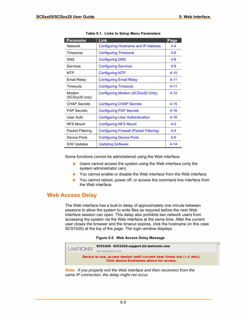
SCSxx05/SCSxx20 User Guide 5: Web Interface
5-3
Table 5-1. Links to Setup Menu Parameters
Parameter Link Page Network Configuring Hostname and IP Address 4-4
Timezone Configuring Timezone 4-6
DNS Configuring DNS 4-8
Services Configuring Services 4-9
NTP Configuring NTP 4-10
Email Relay Configuring Email Relay 4-11
Timeouts Configuring Timeouts 4-11
Modem (SCSxx20 only)
Configuring Modem (SCSxx20 Only) 4-12
CHAP Secrets Configuring CHAP Secrets 4-15
PAP Secrets Configuring PAP Secrets 4-16
User Auth. Configuring User Authentication 4-16
NFS Mount Configuring NFS Mount 4-2
Packet Filtering Configuring Firewall (Packet Filtering) 4-4
Device Ports Configuring Device Ports 4-5
S/W Updates Updating Software 4-14
Some functions cannot be administered using the Web interface:
Users cannot access the system using the Web interface (only the system administrator can).
You cannot enable or disable the Web interface from the Web interface. You cannot reboot, power off, or access the command line interface from
the Web interface.
Web Access Delay
The Web interface has a built-in delay of approximately one minute between sessions to allow the system to write files as required before the next Web interface session can open. This delay also prohibits two network users from accessing the system via the Web interface at the same time. After the current user closes the browser and the timeout expires, click the hostname (in this case SCS1620) at the top of the page. The login window displays.
Figure 5-5. Web Access Delay Message
Note: If you properly exit the Web interface and then reconnect from the same IP connection, the delay might not occur.
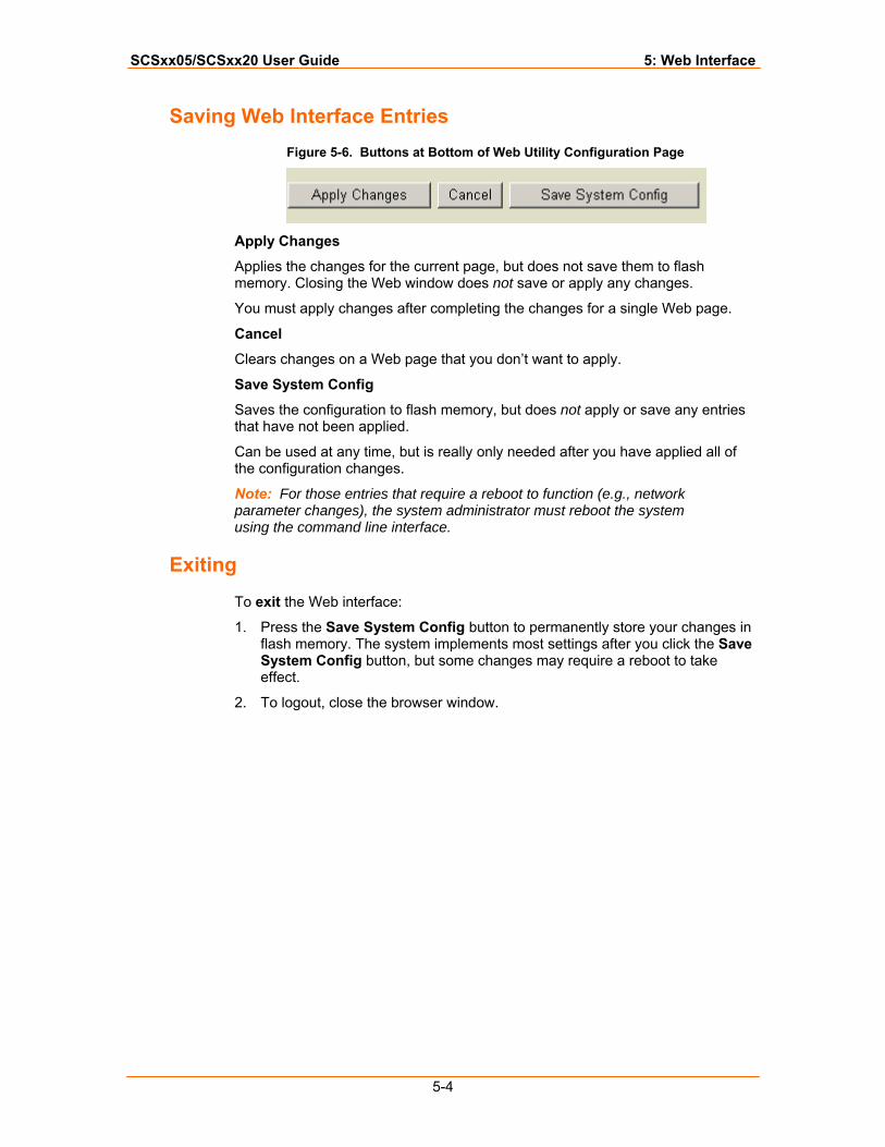
SCSxx05/SCSxx20 User Guide 5: Web Interface
5-4
Saving Web Interface Entries Figure 5-6. Buttons at Bottom of Web Utility Configuration Page
Apply Changes
Applies the changes for the current page, but does not save them to flash memory. Closing the Web window does not save or apply any changes.
You must apply changes after completing the changes for a single Web page.
Cancel
Clears changes on a Web page that you don’t want to apply.
Save System Config
Saves the configuration to flash memory, but does not apply or save any entries that have not been applied.
Can be used at any time, but is really only needed after you have applied all of the configuration changes.
Note: For those entries that require a reboot to function (e.g., network parameter changes), the system administrator must reboot the system using the command line interface.
Exiting
To exit the Web interface:
1. Press the Save System Config button to permanently store your changes in flash memory. The system implements most settings after you click the Save System Config button, but some changes may require a reboot to take effect.
2. To logout, close the browser window.
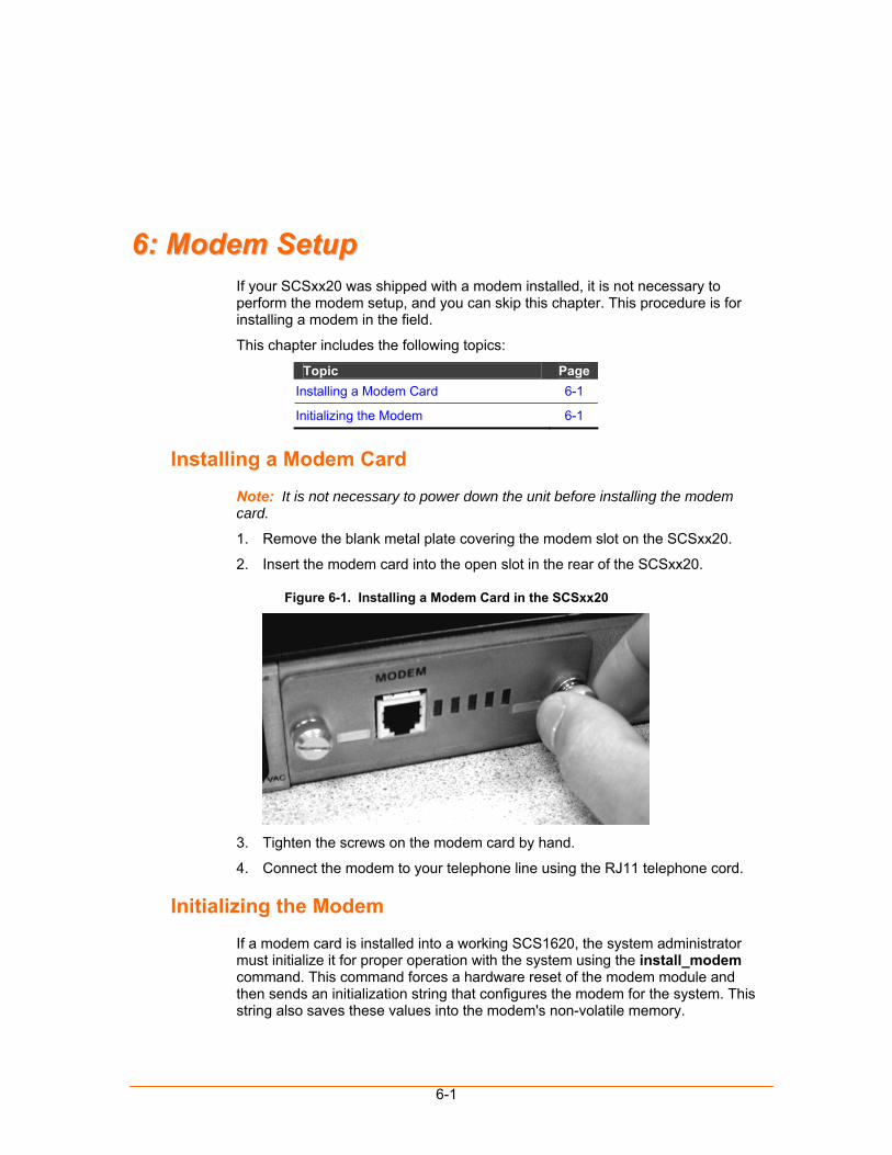
6-1
66:: MMooddeemm SSeettuupp If your SCSxx20 was shipped with a modem installed, it is not necessary to perform the modem setup, and you can skip this chapter. This procedure is for installing a modem in the field.
This chapter includes the following topics:
Topic Page Installing a Modem Card 6-1
Initializing the Modem 6-1
Installing a Modem Card
Note: It is not necessary to power down the unit before installing the modem card.
1. Remove the blank metal plate covering the modem slot on the SCSxx20.
2. Insert the modem card into the open slot in the rear of the SCSxx20.
Figure 6-1. Installing a Modem Card in the SCSxx20
3. Tighten the screws on the modem card by hand.
4. Connect the modem to your telephone line using the RJ11 telephone cord.
Initializing the Modem
If a modem card is installed into a working SCS1620, the system administrator must initialize it for proper operation with the system using the install_modem command. This command forces a hardware reset of the modem module and then sends an initialization string that configures the modem for the system. This string also saves these values into the modem's non-volatile memory.
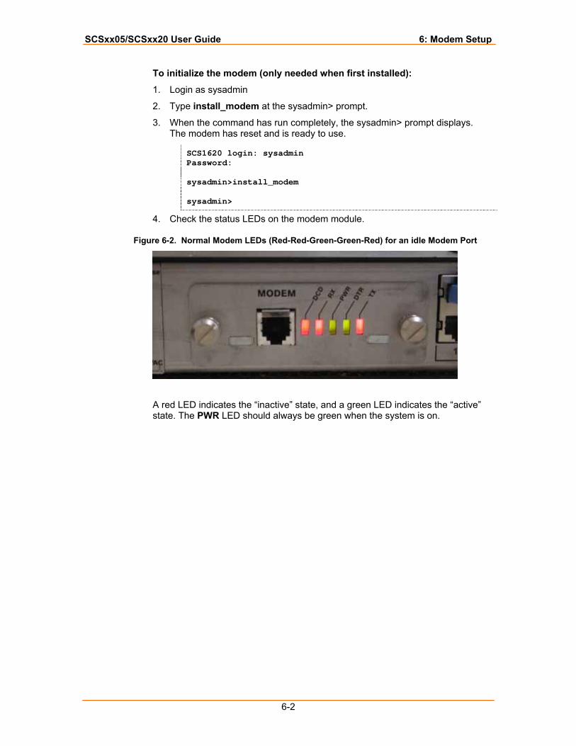
SCSxx05/SCSxx20 User Guide 6: Modem Setup
6-2
To initialize the modem (only needed when first installed):
1. Login as sysadmin
2. Type install_modem at the sysadmin> prompt.
3. When the command has run completely, the sysadmin> prompt displays. The modem has reset and is ready to use.
SCS1620 login: sysadmin Password: sysadmin>install_modem sysadmin>
4. Check the status LEDs on the modem module.
Figure 6-2. Normal Modem LEDs (Red-Red-Green-Green-Red) for an idle Modem Port
A red LED indicates the “inactive” state, and a green LED indicates the “active” state. The PWR LED should always be green when the system is on.
7-1
77:: SSyysstteemm AAddmmiinniissttrraattoorr aanndd UUsseerr FFuunnccttiioonnss This chapter describes how the system administrator and users gain access to the system and the functions permitted for each role. It includes the following topics.
Topic Page System Administrator Functions 7-1
User Access and Functions 7-3
System Administrator Functions
The system administrator specifies settings such as user IDs, device configuration, and terminal and access rights to suit the application. The system administrator is also responsible for configuring the system to work in your network.
The system administrator initially uses Telnet or a terminal to access and configure the SCS, and may choose to use the Web-based interface to update the configuration.
Note: Please see the Configuration chapter for instructions on logging on and logging out as the system administrator.
Security and Passwords The SCS uses Linux/UNIX commands to administer the system. The system administrator and the users access the system using a shell interface, which limits what they can affect in the operating system.
Note: This guide discusses applicable Linux commands only.
The shell offers the appropriate level of administration while maintaining the integrity of the system. The system administrator should change passwords upon installation to protect the system.
The sysadmin programming level is as close to “root” as is required to administer the SCS, but it is not the most senior root level. The most senior root level is intentionally removed from the shell; however, it exists in the system and the system administrator must change its password to protect against unauthorized access or changes.
Changing the Sysadmin Password The system administrator must change the password for the sysadmin level before connecting the SCS to a network or making it accessible to others. The passwd command is discussed in the Commands chapter.
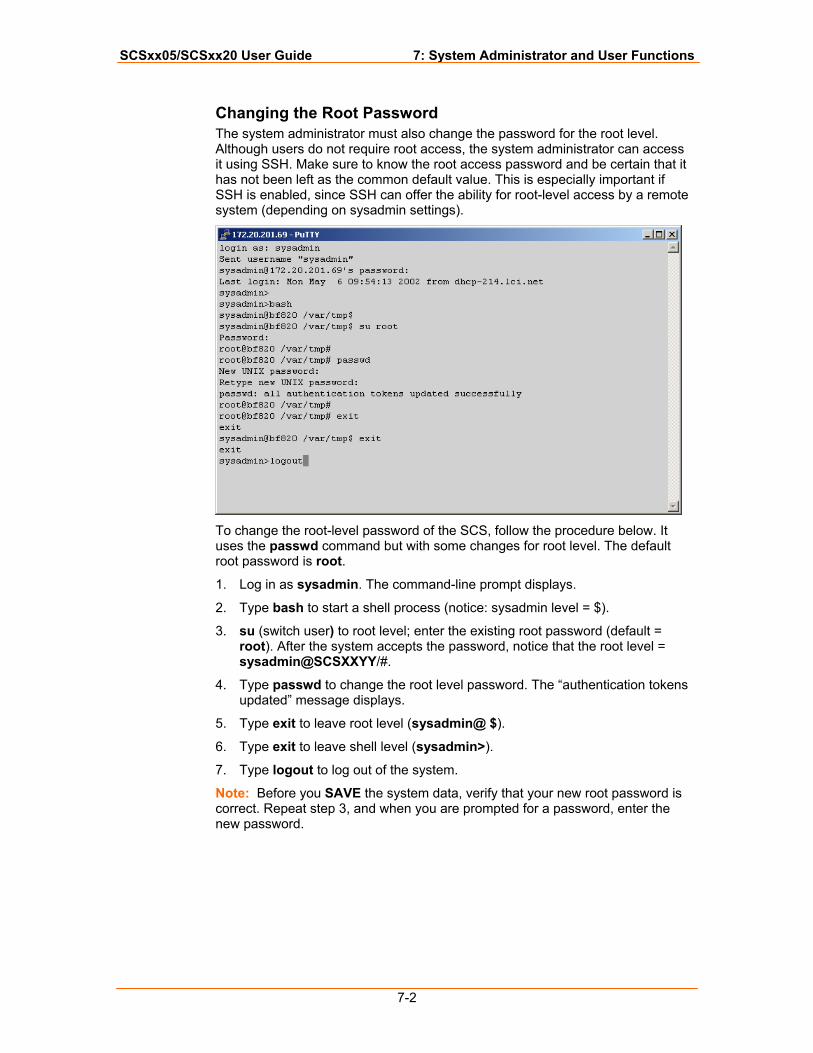
SCSxx05/SCSxx20 User Guide 7: System Administrator and User Functions
7-2
Changing the Root Password The system administrator must also change the password for the root level. Although users do not require root access, the system administrator can access it using SSH. Make sure to know the root access password and be certain that it has not been left as the common default value. This is especially important if SSH is enabled, since SSH can offer the ability for root-level access by a remote system (depending on sysadmin settings).
To change the root-level password of the SCS, follow the procedure below. It uses the passwd command but with some changes for root level. The default root password is root.
1. Log in as sysadmin. The command-line prompt displays.
2. Type bash to start a shell process (notice: sysadmin level = $).
3. su (switch user) to root level; enter the existing root password (default = root). After the system accepts the password, notice that the root level = sysadmin@SCSXXYY/#.
4. Type passwd to change the root level password. The “authentication tokens updated” message displays.
5. Type exit to leave root level (sysadmin@ $).
6. Type exit to leave shell level (sysadmin>).
7. Type logout to log out of the system.
Note: Before you SAVE the system data, verify that your new root password is correct. Repeat step 3, and when you are prompted for a password, enter the new password.
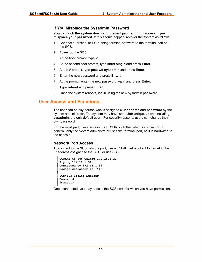
SCSxx05/SCSxx20 User Guide 7: System Administrator and User Functions
7-3
If You Misplace the Sysadmin Password You can lock the system down and prevent programming access if you misplace your password. If this should happen, recover the system as follows:
1. Connect a terminal or PC running terminal software to the terminal port on the SCS.
2. Power up the SCS.
3. At the boot prompt, type ?.
4. At the second boot prompt, type linux single and press Enter.
5. At the # prompt, type passwd sysadmin and press Enter.
6. Enter the new password and press Enter.
7. At the prompt, enter the new password again and press Enter.
8. Type reboot and press Enter.
9. Once the system reboots, log in using the new sysadmin password.
User Access and Functions
The user can be any person who is assigned a user name and password by the system administrator. The system may have up to 200 unique users (including sysadmin, the only default user). For security reasons, users can change their own password.
For the most part, users access the SCS through the network connection. In general, only the system administrator uses the terminal port, as it is hardwired to the chassis.
Network Port Access To connect to the SCS network port, use a TCP/IP Telnet client to Telnet to the IP address assigned to the SCS, or use SSH.
OCTANE_65 10# Telnet 172.16.1.31 Trying 172.16.1.31... Connected to 172.16.1.31 Escape character is ‘^]’. SCS4805 login: imauser Password: imauser>
Once connected, you may access the SCS ports for which you have permission.
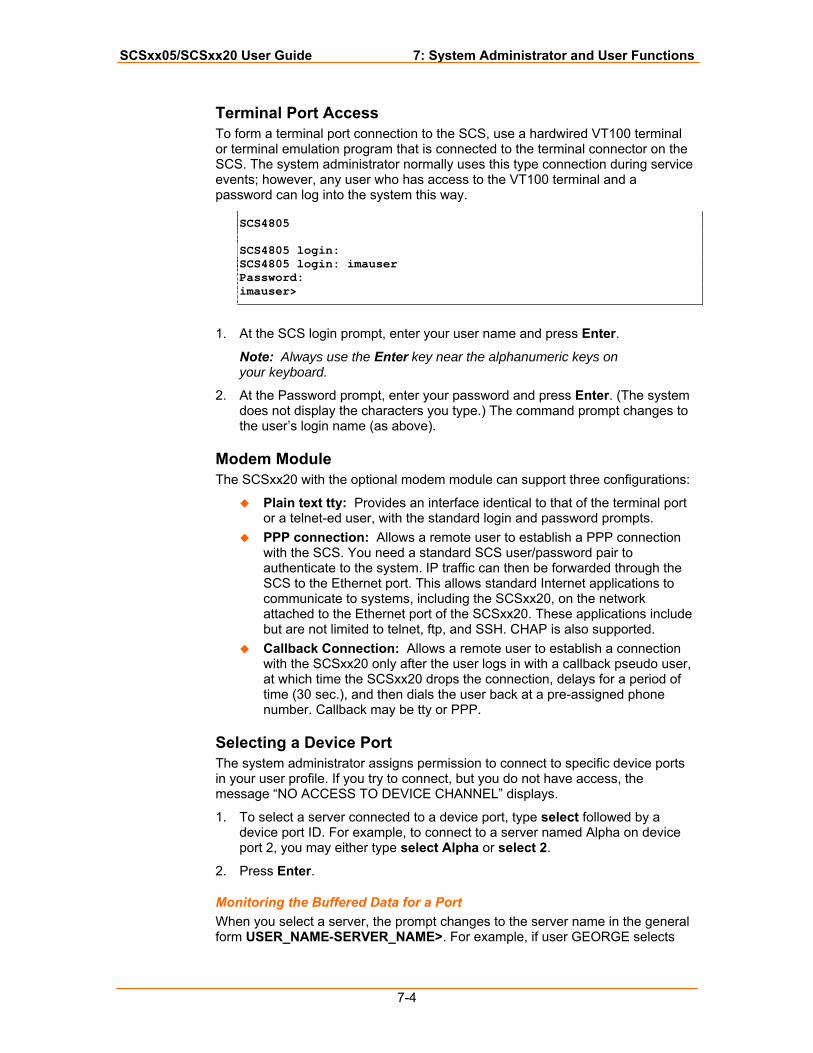
SCSxx05/SCSxx20 User Guide 7: System Administrator and User Functions
7-4
Terminal Port Access To form a terminal port connection to the SCS, use a hardwired VT100 terminal or terminal emulation program that is connected to the terminal connector on the SCS. The system administrator normally uses this type connection during service events; however, any user who has access to the VT100 terminal and a password can log into the system this way.
SCS4805 SCS4805 login: SCS4805 login: imauser Password: imauser>
1. At the SCS login prompt, enter your user name and press Enter.
Note: Always use the Enter key near the alphanumeric keys on your keyboard.
2. At the Password prompt, enter your password and press Enter. (The system does not display the characters you type.) The command prompt changes to the user’s login name (as above).
Modem Module The SCSxx20 with the optional modem module can support three configurations:
Plain text tty: Provides an interface identical to that of the terminal port or a telnet-ed user, with the standard login and password prompts.
PPP connection: Allows a remote user to establish a PPP connection with the SCS. You need a standard SCS user/password pair to authenticate to the system. IP traffic can then be forwarded through the SCS to the Ethernet port. This allows standard Internet applications to communicate to systems, including the SCSxx20, on the network attached to the Ethernet port of the SCSxx20. These applications include but are not limited to telnet, ftp, and SSH. CHAP is also supported.
Callback Connection: Allows a remote user to establish a connection with the SCSxx20 only after the user logs in with a callback pseudo user, at which time the SCSxx20 drops the connection, delays for a period of time (30 sec.), and then dials the user back at a pre-assigned phone number. Callback may be tty or PPP.
Selecting a Device Port The system administrator assigns permission to connect to specific device ports in your user profile. If you try to connect, but you do not have access, the message “NO ACCESS TO DEVICE CHANNEL” displays.
1. To select a server connected to a device port, type select followed by a device port ID. For example, to connect to a server named Alpha on device port 2, you may either type select Alpha or select 2.
2. Press Enter.
Monitoring the Buffered Data for a Port When you select a server, the prompt changes to the server name in the general form USER_NAME-SERVER_NAME>. For example, if user GEORGE selects
SCSxx05/SCSxx20 User Guide 7: System Administrator and User Functions
7-5
Alpha, the prompt would read GEORGE-Alpha>. When this prompt displays, you are in monitor mode. There is no direct communication between you and the server.
Note: You may select a server already selected by another user.
The system saves any output from the server to a buffer that you may access (using cat or less), but you may not issue commands to the server. If you want to issue commands to the server, you must enter direct mode.
Deselecting a Server You may exit from the current device port by using the exit command or selecting another device port.
Direct Mode If you want to interact directly with a server rather than only monitor its output, you must enter direct mode.
To enter direct mode using the direct or dir n command:
1. Select a device port.
2. Do one of the following:
To enter direct mode for the currently selected device port only, enter the direct command.
To select a device port and enter direct mode in one step, enter the dir n command, where n is the device port number or the name assigned to the port.
3. Press Enter.
Your terminal directly connects to the server and acts as if the terminal was physically connected to the server. The SCS displays the last page of the device buffer along with a system information message indicating the device port selected.
To escape from direct mode, use the direct mode escape sequence. The direct mode escape sequence is a series of two to five characters that allow you to leave direct mode and return to monitor mode. The factory default for the direct mode escape sequence is Esc+A (escape key, then uppercase "a"); you may change the sequence by using the editesc command.
Edit Escape Sequence We recommend that you only change the escape sequence if it causes problems with your hardware or software. Also, we recommend that you avoid combinations of the Ctrl key and other keys, as these combinations are usually for sending and receiving special characters through the terminal. When you change the escape sequence, a window with the hexadecimal representation of the old escape sequence displays.
Note: Pressing Esc to exit from the edit prompt does not work; it adds more Esc characters to the direct mode escape sequence. Use \x to prefix any hexadecimal characters entered in the escape sequence. (The default sequence is \x1BA = Esc+A, where 1B is the Hex value for Esc, and A is the letter A.)
To keep the existing sequence, press Enter.
SCSxx05/SCSxx20 User Guide 7: System Administrator and User Functions
7-6
To change the sequence, enter the new sequence and press Enter. If for some reason the sequence is unacceptable, an error message displays, and the sequence reverts to the existing character values.
A list of hexadecimal character settings is provided at the end of this User Guide.
Logging Out Always log out when you are finished with your session activity.
To log out from a user session:
1. Type logout.
2. Press Enter.
If you are logging out from a network, the SCS disconnects the Telnet or SSH session. If you are logging out from a direct serial session, the SCS returns to the login prompt.
The system administrator may configure the SCS to automatically log you out if the terminal connection has been idle for a period of time. This is a security precaution. Depending on your terminal's settings, you may have an inactive window open if the SCS has disconnected.
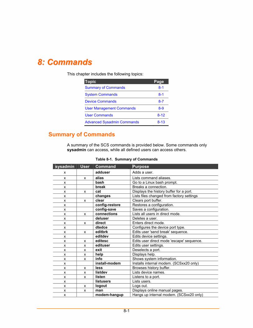
8-1
88:: CCoommmmaannddss This chapter includes the following topics:
Topic Page Summary of Commands 8-1
System Commands 8-1
Device Commands 8-7
User Management Commands 8-9
User Commands 8-12
Advanced Sysadmin Commands 8-13
Summary of Commands
A summary of the SCS commands is provided below. Some commands only sysadmin can access, while all defined users can access others.
Table 8-1. Summary of Commands
sysadmin User Command Purpose x adduser Adds a user. x x alias Lists command aliases. x bash Go to a Linux bash prompt. x break Breaks a connection. x x cat Displays the history buffer for a port. x changes Lists files changed from factory settings x x clear Clears port buffer. x config-restore Restores a configuration. x config-save Saves a configuration. x x connections Lists all users in direct mode. x deluser Deletes a user. x x direct Enters direct mode. x dtedce Configures the device port type. x x editbrk Edits user 'send break' sequence. x editdev Edits device settings. x x editesc Edits user direct mode 'escape' sequence. x x edituser Edits user settings. x x exit Deselects a port. x x help Displays help. x x info Shows system information. x install-modem Installs internal modem. (SCSxx20 only) x x less Browses history buffer. x x listdev Lists device names. x x listen Listens to a port. x listusers Lists users. x x logout Logs out. x x man Displays online manual pages. x modem-hangup Hangs up internal modem. (SCSxx20 only)
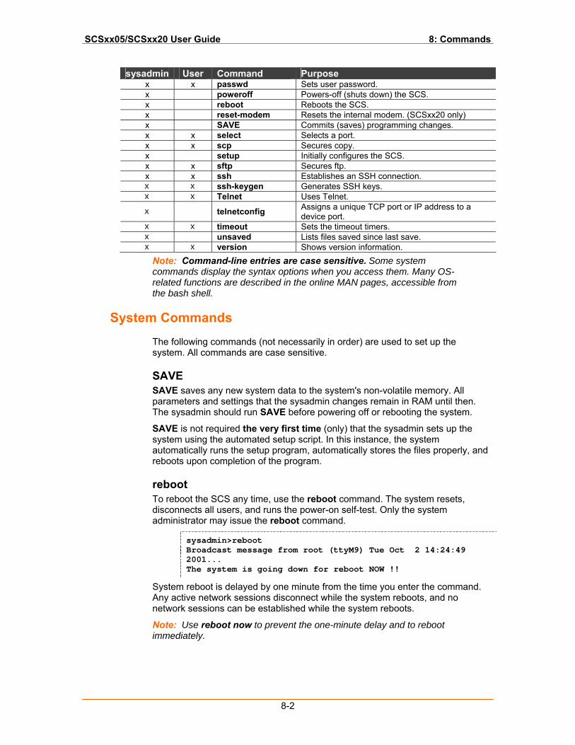
SCSxx05/SCSxx20 User Guide 8: Commands
8-2
sysadmin User Command Purpose x x passwd Sets user password. x poweroff Powers-off (shuts down) the SCS. x reboot Reboots the SCS. x reset-modem Resets the internal modem. (SCSxx20 only) x SAVE Commits (saves) programming changes. x x select Selects a port. x x scp Secures copy. x setup Initially configures the SCS. x x sftp Secures ftp. x x ssh Establishes an SSH connection. x x ssh-keygen Generates SSH keys. x x Telnet Uses Telnet.
x telnetconfig Assigns a unique TCP port or IP address to a device port.
x x timeout Sets the timeout timers. x unsaved Lists files saved since last save. x x version Shows version information.
Note: Command-line entries are case sensitive. Some system commands display the syntax options when you access them. Many OS-related functions are described in the online MAN pages, accessible from the bash shell.
System Commands
The following commands (not necessarily in order) are used to set up the system. All commands are case sensitive.
SAVE SAVE saves any new system data to the system's non-volatile memory. All parameters and settings that the sysadmin changes remain in RAM until then. The sysadmin should run SAVE before powering off or rebooting the system.
SAVE is not required the very first time (only) that the sysadmin sets up the system using the automated setup script. In this instance, the system automatically runs the setup program, automatically stores the files properly, and reboots upon completion of the program.
reboot To reboot the SCS any time, use the reboot command. The system resets, disconnects all users, and runs the power-on self-test. Only the system administrator may issue the reboot command.
sysadmin>reboot Broadcast message from root (ttyM9) Tue Oct 2 14:24:49 2001... The system is going down for reboot NOW !!
System reboot is delayed by one minute from the time you enter the command. Any active network sessions disconnect while the system reboots, and no network sessions can be established while the system reboots.
Note: Use reboot now to prevent the one-minute delay and to reboot immediately.
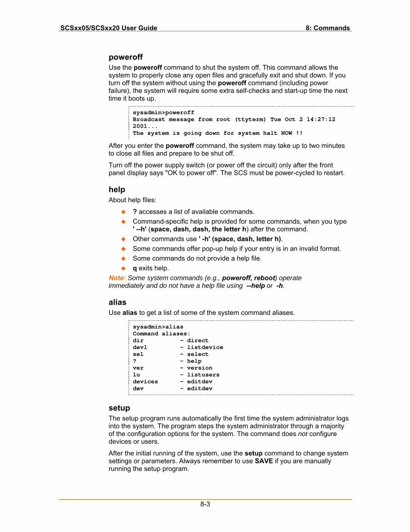
SCSxx05/SCSxx20 User Guide 8: Commands
8-3
poweroff Use the poweroff command to shut the system off. This command allows the system to properly close any open files and gracefully exit and shut down. If you turn off the system without using the poweroff command (including power failure), the system will require some extra self-checks and start-up time the next time it boots up.
sysadmin>poweroff Broadcast message from root (ttyterm) Tue Oct 2 14:27:12 2001... The system is going down for system halt NOW !!
After you enter the poweroff command, the system may take up to two minutes to close all files and prepare to be shut off.
Turn off the power supply switch (or power off the circuit) only after the front panel display says "OK to power off". The SCS must be power-cycled to restart.
help About help files:
? accesses a list of available commands. Command-specific help is provided for some commands, when you type
' --h' (space, dash, dash, the letter h) after the command. Other commands use ' -h' (space, dash, letter h). Some commands offer pop-up help if your entry is in an invalid format. Some commands do not provide a help file. q exits help.
Note: Some system commands (e.g., poweroff, reboot) operate immediately and do not have a help file using --help or -h.
alias Use alias to get a list of some of the system command aliases.
sysadmin>alias Command aliases: dir - direct devl - listdevice sel - select ? - help ver - version lu - listusers devices - editdev dev - editdev
setup The setup program runs automatically the first time the system administrator logs into the system. The program steps the system administrator through a majority of the configuration options for the system. The command does not configure devices or users.
After the initial running of the system, use the setup command to change system settings or parameters. Always remember to use SAVE if you are manually running the setup program.
SCSxx05/SCSxx20 User Guide 8: Commands
8-4
passwd At the first login, the SCS uses the factory default password, PASS (all upper case). The sysadmin should change this default password as soon as possible to prevent access by unauthorized personnel.
sysadmin>passwd Changing password for sysadmin (current) UNIX password: New UNIX password: Retype new UNIX password: passwd: all authentication tokens updated successfully sysadmin>
To change the sysadmin factory default password, type passwd (all lower case) at the sysadmin> prompt. The system prompts you to enter a new password. The new password must be six or more alphanumeric characters and is case-sensitive.
The sysadmin must also change the root password. While root access is not required in the SCS system; changing the root password from the default ensures the security of your system. The root password is more senior than the sysadmin password and is administered differently. (See Changing the Root Password.)
break Use this command to break a connection. The syntax is break <port # > (e.g., break 1, break 2, break 3).
changes Use this command to list files that have been changed from factory settings.
config-save Use this command to place a backup of the system configuration on the ftp or tftp server configured in the setup process. The sysadmin must first configure the ftp/tftp server parameters as described in Updating Software.
config-restore Use this command to load the saved backup of the system configuration from the ftp or tftp server configured in the setup process. The sysadmin must first configure the ftp/tftp server parameters as described in Updating Software.
install-modem Use this command to install an internal modem. (SCSxx20 only)
man Use man <command name> to search for a help file (online manual pages) or descriptive information for a Linux/UNIX command.
modem-hangup Use this command to hang up an internal modem. (SCSxx20 only)
info The info command displays the shell version.
SCSxx05/SCSxx20 User Guide 8: Commands
8-5
sysadmin> sysadmin>info SCS4805 Shell V4.00 sysadmin>
reset-modem Use this command to reset the internal modem. (SCSxx20 only)
scp Use scp to perform a secure copy, using SSH, between two hosts. The file copy is encrypted and is therefore secure.
Refer to the man pages for scp for a description and command options.
sftp Use sftp to perform a secure file transfer transaction, using SSH, between two servers. It is similar to ftp except that it is encrypted for security.
Refer to the man pages for sftp for a description and command options.
ssh Use ssh to open up a secure shell connection between two hosts to transfer files or data between the systems. In this case, the SCS is a client device and is connected to an SSH host elsewhere. You may need to generate the security keys for SSH using ssh-keygen, depending on your application of SSH.
Refer to the man pages for SSH for a description and command options.
ssh-keygen Use ssh-keygen to create the security keys for your client system to interact with an SSH host elsewhere. After the keys have been generated, the user can establish a secure shell connection using SSH over a network.
See Advanced Sysadmin Commands later in this chapter for an ssh-keygen tutorial. Refer to the man pages for SSH for a description and command options.
syslog The SCS keeps a system log file called /var/log/syslog. The level of logging is controlled by the file /etc/syslog.conf.
The SCS can log the following:
Warning level events: no events Notice level events: − Device settings changed − Begin and end direct mode − Device buffer cleared − Begin and end listen mode − Begin and end bash shell
Info level events − User settings modified − User begin and end of SCS command shell − Device selected − Device unselected (exit command)
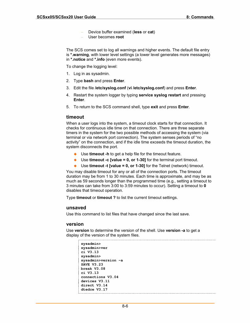
SCSxx05/SCSxx20 User Guide 8: Commands
8-6
− Device buffer examined (less or cat) − User becomes root
The SCS comes set to log all warnings and higher events. The default file entry is *.warning, with lower level settings (a lower level generates more messages) in *.notice and *.info (even more events).
To change the logging level:
1. Log in as sysadmin.
2. Type bash and press Enter.
3. Edit the file /etc/syslog.conf (vi /etc/syslog.conf) and press Enter.
4. Restart the system logger by typing service syslog restart and pressing Enter.
5. To return to the SCS command shell, type exit and press Enter.
timeout When a user logs into the system, a timeout clock starts for that connection. It checks for continuous idle time on that connection. There are three separate timers in the system for the two possible methods of accessing the system (via terminal or via network port connection). The system senses periods of “no activity” on the connection, and if the idle time exceeds the timeout duration, the system disconnects the port.
Use timeout -h to get a help file for the timeout feature. Use timeout -c [value = 0, or 1-30] for the terminal port timeout. Use timeout -t [value = 0, or 1-30] for the Telnet (network) timeout.
You may disable timeout for any or all of the connection ports. The timeout duration may be from 1 to 30 minutes. Each time is approximate, and may be as much as 59 seconds longer than the programmed time (e.g., setting a timeout to 3 minutes can take from 3:00 to 3:59 minutes to occur). Setting a timeout to 0 disables that timeout operation.
Type timeout or timeout ? to list the current timeout settings.
unsaved Use this command to list files that have changed since the last save.
version Use version to determine the version of the shell. Use version -a to get a display of the version of the system files.
sysadmin> sysadmin>ver ci V3.13 sysadmin> sysadmin>version -a SAVE V3.23 break V3.08 ci V3.13 connections V3.04 devices V3.11 direct V3.14 dtedce V3.17
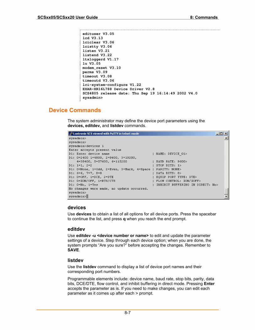
SCSxx05/SCSxx20 User Guide 8: Commands
8-7
edituser V3.05 lcd V3.13 lciclear V3.06 lcistty V3.06 listen V3.21 listend V3.22 ltxloggerd V1.17 lu V3.05 modem_reset V3.10 perms V3.09 timeout V3.08 timeoutd V3.06 lci-system-configure V1.22 EXAR-XR16L788 Device Driver V2.8 SCS4805 release date: Thu Sep 19 16:14:49 2002 V4.0 sysadmin>
Device Commands
The system administrator may define the device port parameters using the devices, editdev, and listdev commands.
devices Use devices to obtain a list of all options for all device ports. Press the spacebar to continue the list, and press q when you reach the end prompt.
editdev Use editdev -u <device number or name> to edit and update the parameter settings of a device. Step through each device option; when you are done, the system prompts “Are you sure?” before accepting the changes. Remember to SAVE.
listdev Use the listdev command to display a list of device port names and their corresponding port numbers.
Programmable elements include: device name, baud rate, stop bits, parity, data bits, DCE/DTE, flow control, and inhibit buffering in direct mode. Pressing Enter accepts the parameter as is. If you need to make changes, you can edit each parameter as it comes up after each > prompt.
SCSxx05/SCSxx20 User Guide 8: Commands
8-8
Device Name The device name cannot contain a space. Use an underscore if you need an empty space in the name.
Baud Rate Seven device baud rates are offered: 2400, 4800, 9600, 19200, 38400, 57600, and 115,200. Most devices use 9600 as the terminal/administration port's baud rate, so the device port defaults to this value. Check the equipment settings and documentation for the proper baud rate.
Stop Bits, Parity, Data Bits The stop bits, parity, and data bits parameters determine the format of the bit-wise transmission of data. The default settings are 1 stop bit, no parity, and 8 data bits. Check your equipment documentation for the proper settings.
DCE/DTE The SCSxx05 device and terminal ports are factory configured as DTE devices. The SCSxx20 device and terminal ports are factory configured as DCE devices.
Flow Control The device port flow control setting determines the method of flow control. The two most common settings are XON/XOFF (software) and RTS/CTS (hardware). The default setting for the device ports is XON/XOFF. Check the equipment documentation for the correct flow control setting.
Buffering The Inhibit Buffering in Direct setting allows the administrator to turn off port buffering while a user is connected to the device and is in direct mode. The device port buffer still collects data while not in direct mode when this setting is active. You may disable direct mode buffering so other users cannot view sensitive data, but the system stores alert and panic messages from the attached device when nobody is connected. This setting is disabled by default, so buffer data is collected both in and out of direct mode.
connections Use connections to display a snapshot list of all users connected in direct mode.
cat Use cat <port name or number> to display the buffer information for that port.
clear Use clear <port name or number> to clear the buffer for that port.
less Use less <port name or number> to browse the buffer for that port. When the buffer reaches the capacity of the screen, it pauses; press the spacebar to continue the display. When the buffer reaches the end, it displays "END"; press q to quit the less program and return to the command line.
logout Use logout to quit your session with the system.
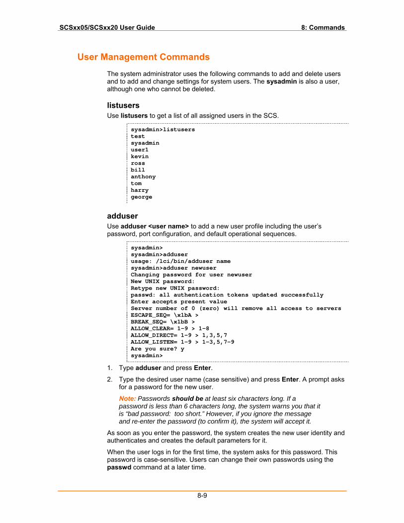
SCSxx05/SCSxx20 User Guide 8: Commands
8-9
User Management Commands
The system administrator uses the following commands to add and delete users and to add and change settings for system users. The sysadmin is also a user, although one who cannot be deleted.
listusers Use listusers to get a list of all assigned users in the SCS.
sysadmin>listusers test sysadmin user1 kevin ross bill anthony tom harry george
adduser Use adduser <user name> to add a new user profile including the user’s password, port configuration, and default operational sequences.
sysadmin> sysadmin>adduser usage: /lci/bin/adduser name sysadmin>adduser newuser Changing password for user newuser New UNIX password: Retype new UNIX password: passwd: all authentication tokens updated successfully Enter accepts present value Server number of 0 (zero) will remove all access to servers ESCAPE_SEQ= \x1bA > BREAK_SEQ= \x1bB > ALLOW_CLEAR= 1-9 > 1-8 ALLOW_DIRECT= 1-9 > 1,3,5,7 ALLOW_LISTEN= 1-9 > 1-3,5,7-9 Are you sure? y sysadmin>
1. Type adduser and press Enter.
2. Type the desired user name (case sensitive) and press Enter. A prompt asks for a password for the new user.
Note: Passwords should be at least six characters long. If a password is less than 6 characters long, the system warns you that it is “bad password: too short.” However, if you ignore the message and re-enter the password (to confirm it), the system will accept it.
As soon as you enter the password, the system creates the new user identity and authenticates and creates the default parameters for it.
When the user logs in for the first time, the system asks for this password. This password is case-sensitive. Users can change their own passwords using the passwd command at a later time.
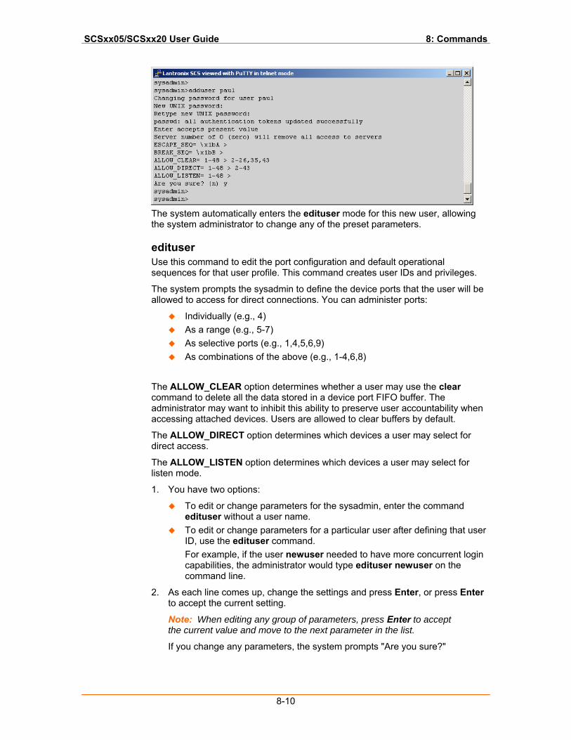
SCSxx05/SCSxx20 User Guide 8: Commands
8-10
The system automatically enters the edituser mode for this new user, allowing the system administrator to change any of the preset parameters.
edituser Use this command to edit the port configuration and default operational sequences for that user profile. This command creates user IDs and privileges.
The system prompts the sysadmin to define the device ports that the user will be allowed to access for direct connections. You can administer ports:
Individually (e.g., 4) As a range (e.g., 5-7) As selective ports (e.g., 1,4,5,6,9) As combinations of the above (e.g., 1-4,6,8)
The ALLOW_CLEAR option determines whether a user may use the clear command to delete all the data stored in a device port FIFO buffer. The administrator may want to inhibit this ability to preserve user accountability when accessing attached devices. Users are allowed to clear buffers by default.
The ALLOW_DIRECT option determines which devices a user may select for direct access.
The ALLOW_LISTEN option determines which devices a user may select for listen mode.
1. You have two options:
To edit or change parameters for the sysadmin, enter the command edituser without a user name.
To edit or change parameters for a particular user after defining that user ID, use the edituser command. For example, if the user newuser needed to have more concurrent login capabilities, the administrator would type edituser newuser on the command line.
2. As each line comes up, change the settings and press Enter, or press Enter to accept the current setting.
Note: When editing any group of parameters, press Enter to accept the current value and move to the next parameter in the list.
If you change any parameters, the system prompts "Are you sure?"
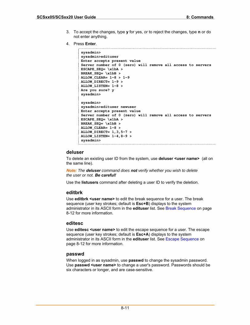
SCSxx05/SCSxx20 User Guide 8: Commands
8-11
3. To accept the changes, type y for yes, or to reject the changes, type n or do not enter anything.
4. Press Enter.
sysadmin> sysadmin>edituser Enter accepts present value Server number of 0 (zero) will remove all access to servers ESCAPE_SEQ= \x1bA > BREAK_SEQ= \x1bB > ALLOW_CLEAR= 1-8 > 1-9 ALLOW_DIRECT= 1-9 > ALLOW_LISTEN= 1-8 > Are you sure? y sysadmin> sysadmin> sysadmin>edituser newuser Enter accepts present value Server number of 0 (zero) will remove all access to servers ESCAPE_SEQ= \x1bA > BREAK_SEQ= \x1bB > ALLOW_CLEAR= 1-8 > ALLOW_DIRECT= 1,3,5-7 > ALLOW_LISTEN= 1-4,8-9 > sysadmin>
deluser To delete an existing user ID from the system, use deluser <user name> (all on the same line).
Note: The deluser command does not verify whether you wish to delete the user or not. Be careful!
Use the listusers command after deleting a user ID to verify the deletion.
editbrk Use editbrk <user name> to edit the break sequence for a user. The break sequence (user key strokes; default is Esc+B) displays to the system administrator in its ASCII form in the edituser list. See Break Sequence on page 8-12 for more information.
editesc Use editesc <user name> to edit the escape sequence for a user. The escape sequence (user key strokes; default is Esc+A) displays to the system administrator in its ASCII form in the edituser list. See Escape Sequence on page 8-12 for more information.
passwd When logged in as sysadmin, use passwd to change the sysadmin password. Use passwd <user name> to change a user's password. Passwords should be six characters or longer, and are case-sensitive.
SCSxx05/SCSxx20 User Guide 8: Commands
8-12
User Commands
After the user logs in to the system, the user name becomes the command prompt. For example, ross> displays after Ross logs in.
Users log in to identify themselves to the system and to access the device ports to which the system administrator has assigned them privileges.
select Use select <port name or number> to select a port (only applies to ports for which this user is allowed clear, direct, or listen access).
direct Use direct <port name or number> to connect to a port (only applies to a port for which this user is allowed direct access).
telnetconfig Use telnetconfig < port name or number> or telnetconfig <IP address> to assign a unique TCP port or IP address to a device port so that Telnet can be used to connect to the device port. Only the sysadmin user has permission to run telnetconfig. Users who wish to Telnet to a device port must have must have direct access rights to use this command.
listen Use listen <port name or number> to listen to a port (only applies to ports for which this user is allowed listen access).
clear Use clear <port name or number> to clear the buffer of a device port (only applies to ports for which this user is allowed clear access).
exit Use exit to disconnect from a port that you are connected to. When you are disconnected, the command line displays.
logout The user can log out of a port connection by typing logout on the command line.
Break Sequence The user can send a break signal to the external device using a programmed break sequence. The preset value for this option is Esc+B (performed quickly but not simultaneously).
Escape Sequence The user can disconnect from a port by using a programmed escape sequence. The preset value for this option is Esc+A (performed quickly but not simultaneously).
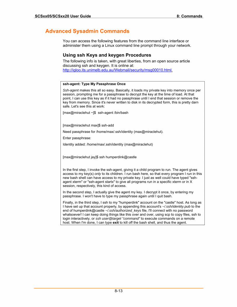
SCSxx05/SCSxx20 User Guide 8: Commands
8-13
Advanced Sysadmin Commands
You can access the following features from the command line interface or administer them using a Linux command line prompt through your network.
Using ssh Keys and keygen Procedures The following info is taken, with great liberties, from an open source article discussing ssh and keygen. It is online at: http://igloo.its.unimelb.edu.au/Webmail/security/msg00010.html.
ssh-agent: Type My Passphrase Once
Ssh-agent makes this all so easy. Basically, it loads my private key into memory once per session, prompting me for a passphrase to decrypt the key at the time of load. At that point, I can use this key as if it had no passphrase until I end that session or remove the key from memory. Since it's never written to disk in its decrypted form, this is pretty darn safe. Let's see this at work:
[max@miraclehut ~]$ ssh-agent /bin/bash
[max@miraclehut max]$ ssh-add
Need passphrase for /home/max/.ssh/identity (max@miraclehut).
Enter passphrase:
Identity added: /home/max/.ssh/identity (max@miraclehut)
[max@miraclehut jay]$ ssh humperdink@castle
In the first step, I invoke the ssh-agent, giving it a child program to run. The agent gives access to my key(s) only to its children. I run bash here, so that every program I run in this new bash shell can have access to my private key. I just as well could have typed "ssh-agent xterm" or "ssh-agent startx" to give all programs run in a specific xterm or in X session, respectively, this kind of access.
In the second step, I actually give the agent my key. I decrypt it once, by entering my passphrase. I won't have to type my passphrase again until I quit bash.
Finally, in the third step, I ssh to my "humperdink" account on the "castle" host. As long as I have set up that account properly, by appending this account's ~/.ssh/identity.pub to the end of humperdink@castle ~/.ssh/authorized_keys file, I'll connect with no password whatsoever! I can keep doing things like this over and over, using scp to copy files, ssh to login interactively, or ssh user@target "command" to execute commands on a remote host. When I'm done, I can type exit to kill off the bash shell, and thus the agent.
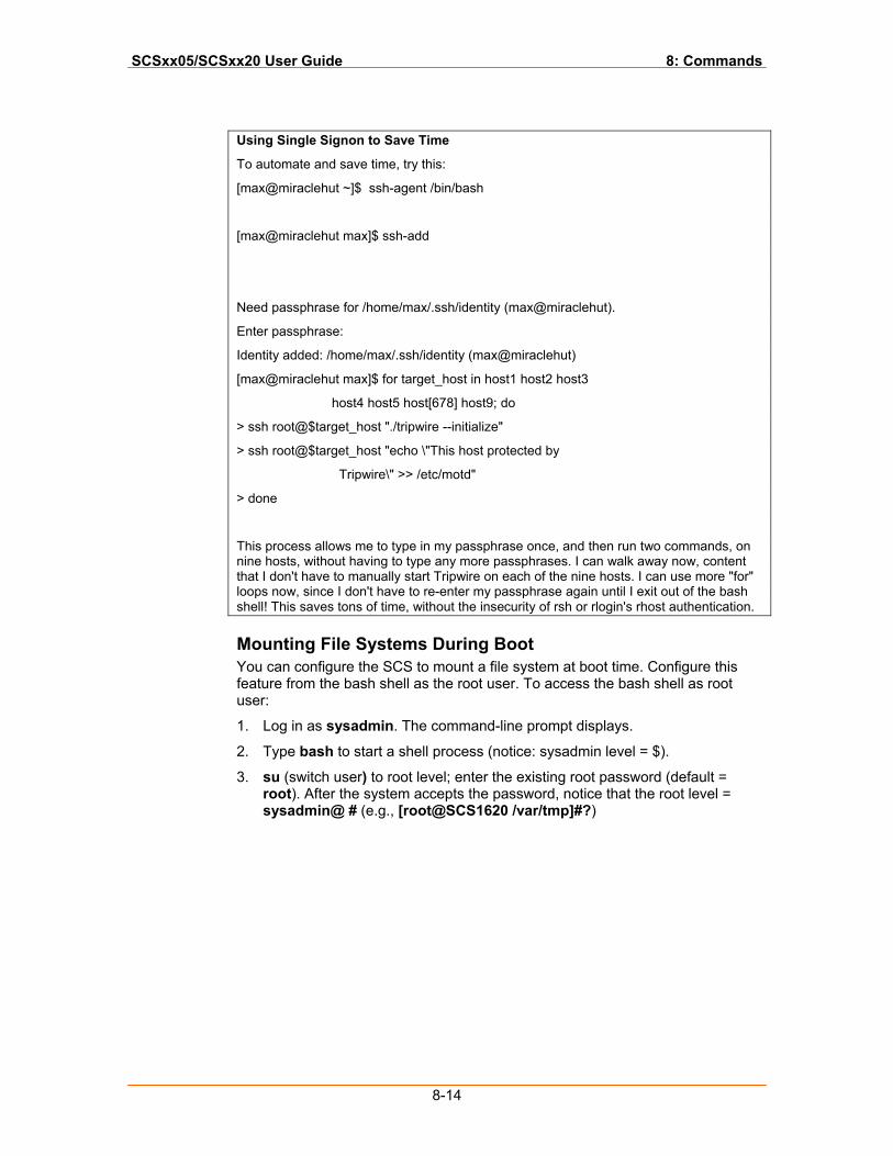
SCSxx05/SCSxx20 User Guide 8: Commands
8-14
Using Single Signon to Save Time
To automate and save time, try this:
[max@miraclehut ~]$ ssh-agent /bin/bash
[max@miraclehut max]$ ssh-add
Need passphrase for /home/max/.ssh/identity (max@miraclehut).
Enter passphrase:
Identity added: /home/max/.ssh/identity (max@miraclehut)
[max@miraclehut max]$ for target_host in host1 host2 host3
host4 host5 host[678] host9; do
> ssh root@$target_host "./tripwire --initialize"
> ssh root@$target_host "echo \"This host protected by
Tripwire\" >> /etc/motd"
> done
This process allows me to type in my passphrase once, and then run two commands, on nine hosts, without having to type any more passphrases. I can walk away now, content that I don't have to manually start Tripwire on each of the nine hosts. I can use more "for" loops now, since I don't have to re-enter my passphrase again until I exit out of the bash shell! This saves tons of time, without the insecurity of rsh or rlogin's rhost authentication.
Mounting File Systems During Boot You can configure the SCS to mount a file system at boot time. Configure this feature from the bash shell as the root user. To access the bash shell as root user:
1. Log in as sysadmin. The command-line prompt displays.
2. Type bash to start a shell process (notice: sysadmin level = $).
3. su (switch user) to root level; enter the existing root password (default = root). After the system accepts the password, notice that the root level = sysadmin@ # (e.g., [root@SCS1620 /var/tmp]#?)
SCSxx05/SCSxx20 User Guide 8: Commands
8-15
To mount a file system at boot time, the /etc/fstab file must have an entry that is associated with the directory to mount. Following is an example of how to use this facility to automatically mount an NFS file on the SCS.
In /etc/fstab the following entry must be present:
/dev/device /dir/to/mount ftype parameters fs_freq fs_passno
where
/dev/device The device to be mounted. In the case of mounting an NFS file system, the entry should be in the form of server name:/dir/exported, where server name is the name of the NFS file server, and the /dir/exported is the exported directory found on the NFS server.
/dir/to/mount The location at which the file system should be mounted on the SCS. This directory has to be defined on the SCS, or it will not work.
ftype The file system type. For an NFS-mounted file system, use nfs.
parameters These are the parameters that are passed to the mount command. They are in a comma-delimited format.
fs_freq This is used by dump to determine whether a file system needs to be dumped.
fs_passno The fsck program uses this to determine the order to check disks at boot time.
An example of an entry in /etc/fstab is as follows:
erh62:/export/var/test /var/test nfs rw,bg,intr,soft 0 0
To manually test whether the system will automatically mount a file system at boot time, enter the following command to manually mount the file:
mount –a
This command reads the /etc/fstab file and mounts all of the entries in the file that are not already mounted. Once the system verifies the /etc/fstab file, you must configure the SCS to have the portmap service and the netfs script executed when the system boots.
To do this, execute the chkconfig command for both. The following commands configure the SCS:
chkconfig –add portmap
chkconfig –add netfs
The system is now configured to start the portmap service and make sure the NFS file system is mounted when the system boots.
Mounting File Systems Dynamically Using autofs autofs is a kernel module that allows the SCS to dynamically mount file systems only when needed. An example would be to have all of the user’s home directories on an NFS-mounted disk. When the user logs into the SCS, the system immediately mounts the user’s directory instead of at boot.
SCSxx05/SCSxx20 User Guide 8: Commands
8-16
You can only configure this feature from the bash shell as the root user. (See instructions for changing to the root user in Mounting File Systems During Boot.)
The following files are needed to insure that autofs works properly:
/usr/sbin/
automount
/etc/rc.d/init.d/
autofs
/etc/
auto.master
auto.export
/usr/lib/autofs/
lookup_file.so mount_ext2.so
lookup_multi.so mount_generic.so
lookup_nisplus.so mount_nfs.so
lookup_program.so parse_sun.so
lookup_userhome.so
lookup_yp.so
mount_afs.so
mount_autofs.so
mount_changer.so
All of these files, with the exception of the two listed in the /etc directory, are system files. The auto.master and auto.export files are configuration files for automount.
The following example describes how to set up the SCS so that whenever user tomv logs into the SCS and accesses its home directory, the system uses the NFS-mounted file system on the erh62 server.
1. Look at the configuration files. The auto.master file tells automount where to mount the list of files that are present in the auto.export file.
a) In auto.master, add the following line:
/export/home /etc/auto.export --timeout 60
where
/export/home The mount point on the SCS. Must be defined.
/etc/auto.export The file that contains the list of mounts for /export/home.
--timeout Number of seconds the mount is inactive before being unmounted. (0 = file will not be unmounted.)
SCSxx05/SCSxx20 User Guide 8: Commands
8-17
b) In the auto.export file, add the following:
tomv -fstype=nfs,rw,intr,soft,bg erh62:/home/tomv
where
tomv The NFS mounted directory name.
fstype The comma-delimited option list that mount will use.
erh62:/home/tomv The server name and directory that the SCS will use.
2. Once the configuration files are complete, start the autofs service by issuing the following command:
service autofs start
For completeness, you can place a symlink in the /home directory:
ln –s /export/home/tomv tomv
Now the user can access the user’s home directory using the path /home/tomv.
If you need to change the autofs configuration files, you must restart the service by doing one of the following:
service autofs restart
or
service autofs stop
service autofs start
9-1
99:: PPoorrtt AAcccceessss The SCS provides various ways of accessing serial ports. This chapter includes the following topics:
Topic Page Telnet to Serial Port 9-1
IP Address per Serial Port Feature 9-5
Telnet to Serial Port Feature
This section describes how to set up and use the Telnet to a Serial Port feature of the SCS. It assumes that you have otherwise configured the unit, and that the console server has connectivity to the network.
The system administrator can assign the serial ports individual IP port numbers and/or distinct IP addresses. You can disable authentication on the console server for directly connected serial ports. This section discusses the setup, use, and security considerations for port access.
Accessing Serial Ports You can set up the Telnet to a Serial Port feature so that you can access a serial port by entering a predefined IP port number on the Telnet client’s command line or by using distinct IP addresses assigned to each serial port. You can set up the console server in several simple steps.
The reason to use one access method or the other is site specific:
If your site has limited IP addresses available, then you may want to define separate IP port numbers for the serial ports and use these numbers in combination with the console server’s IP address.
If you have enough IP addresses available and would like to assign names to each IP address (using your DNS server), then you may want to define an IP address per serial port.
IP Port Numbers If you assign an IP port number to a serial port, enter the full command on the client machine to directly access the serial port:
$ Telnet console_server_ip_addr ip_port_number
or, if the name of the console server can be resolved to an IP address (DNS):
$ Telnet console_server_name ip_port_number
You must predetermine and establish the cross-reference of the console server serial port number and the specific console server IP port number on the console server. To access the proper port, users must be aware of this cross-reference.
If you are using multiple console servers, the IP port number assignments can be the same on each console server. An example of this cross-reference is:
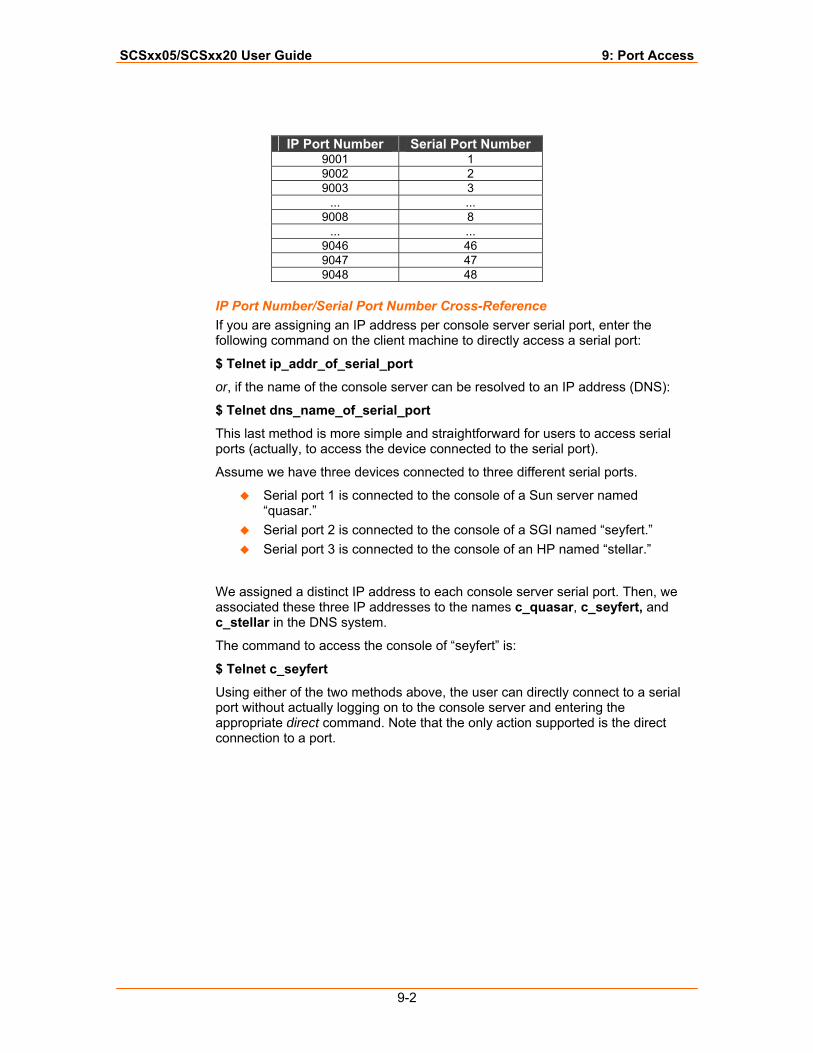
SCSxx05/SCSxx20 User Guide 9: Port Access
9-2
IP Port Number Serial Port Number
9001 1 9002 2 9003 3
... ... 9008 8
... ... 9046 46 9047 47 9048 48
IP Port Number/Serial Port Number Cross-Reference If you are assigning an IP address per console server serial port, enter the following command on the client machine to directly access a serial port:
$ Telnet ip_addr_of_serial_port
or, if the name of the console server can be resolved to an IP address (DNS):
$ Telnet dns_name_of_serial_port
This last method is more simple and straightforward for users to access serial ports (actually, to access the device connected to the serial port).
Assume we have three devices connected to three different serial ports.
Serial port 1 is connected to the console of a Sun server named “quasar.”
Serial port 2 is connected to the console of a SGI named “seyfert.” Serial port 3 is connected to the console of an HP named “stellar.”
We assigned a distinct IP address to each console server serial port. Then, we associated these three IP addresses to the names c_quasar, c_seyfert, and c_stellar in the DNS system.
The command to access the console of “seyfert” is:
$ Telnet c_seyfert
Using either of the two methods above, the user can directly connect to a serial port without actually logging on to the console server and entering the appropriate direct command. Note that the only action supported is the direct connection to a port.

SCSxx05/SCSxx20 User Guide 9: Port Access
9-3
Assigning an IP Port Number to a Serial Port You need to modify two files to assign an IP port number to a serial port.
In our example we specify that:
IP port number 9001 correlates to serial port 1 IP port number 9002 correlates to serial port 2
and so on, up to 9048 correlating to device port 48 in the SCS4805. These IP addresses are simply the default values and the convention chosen in this example. If you choose your own port numbers, ensure that they do not conflict with existing entries in /etc/inetd.conf.
1. The first file to edit is /etc/inetd.conf. In this file, uncomment the existing entries in the (supplied)/etc/inetd.conf, as follows:
a) Log in to the sysadmin account:
sysadmin>bash sysadmin@km3210 /var/tmp$ su Password: root@km3210 /var/tmp# cd /etc root@km3210 /etc# vi inetd.conf
b) Uncomment the entries for ports 9001 to 9017. Save and exit vi. The entries should look like:
9001 stream tcp nowait root /usr/sbin/tcpd in.telnetd
c) Tell the inetd process to re-read the /etc/inetd.conf file:
root@km3210 /etc# kill –SIGHUP `cat /var/run/inetd.pid`
2. Edit the second file, /lci/lwip_serial.conf, as follows:
root@km3210 /etc# cd /lci root@km3210 /lci# vi lwip_serial.conf
3. Uncomment the entries that correspond to the IP port numbers 9001 to 9017 for device ports 1 through 17. The entries should look like:
1 0.0.0.0 9001 1 2 0.0.0.0 9002 1 3 0.0.0.0 9003 1 ... 16 0.0.0.0 9016 1 17 0.0.0.0 9017 1
and so on.
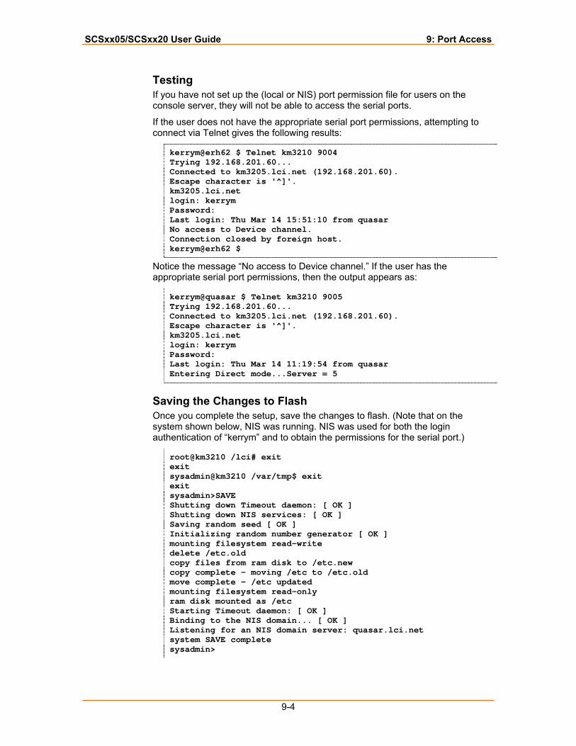
SCSxx05/SCSxx20 User Guide 9: Port Access
9-4
Testing If you have not set up the (local or NIS) port permission file for users on the console server, they will not be able to access the serial ports.
If the user does not have the appropriate serial port permissions, attempting to connect via Telnet gives the following results:
kerrym@erh62 $ Telnet km3210 9004 Trying 192.168.201.60... Connected to km3205.lci.net (192.168.201.60). Escape character is '^]'. km3205.lci.net login: kerrym Password: Last login: Thu Mar 14 15:51:10 from quasar No access to Device channel. Connection closed by foreign host. kerrym@erh62 $
Notice the message “No access to Device channel.” If the user has the appropriate serial port permissions, then the output appears as:
kerrym@quasar $ Telnet km3210 9005 Trying 192.168.201.60... Connected to km3205.lci.net (192.168.201.60). Escape character is '^]'. km3205.lci.net login: kerrym Password: Last login: Thu Mar 14 11:19:54 from quasar Entering Direct mode...Server = 5
Saving the Changes to Flash Once you complete the setup, save the changes to flash. (Note that on the system shown below, NIS was running. NIS was used for both the login authentication of “kerrym” and to obtain the permissions for the serial port.)
root@km3210 /lci# exit exit sysadmin@km3210 /var/tmp$ exit exit sysadmin>SAVE Shutting down Timeout daemon: [ OK ] Shutting down NIS services: [ OK ] Saving random seed [ OK ] Initializing random number generator [ OK ] mounting filesystem read-write delete /etc.old copy files from ram disk to /etc.new copy complete - moving /etc to /etc.old move complete - /etc updated mounting filesystem read-only ram disk mounted as /etc Starting Timeout daemon: [ OK ] Binding to the NIS domain... [ OK ] Listening for an NIS domain server: quasar.lci.net system SAVE complete sysadmin>
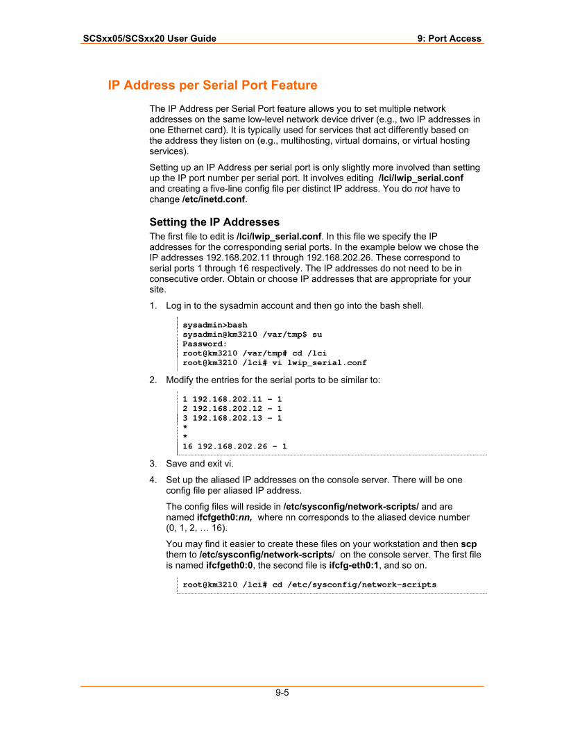
SCSxx05/SCSxx20 User Guide 9: Port Access
9-5
IP Address per Serial Port Feature
The IP Address per Serial Port feature allows you to set multiple network addresses on the same low-level network device driver (e.g., two IP addresses in one Ethernet card). It is typically used for services that act differently based on the address they listen on (e.g., multihosting, virtual domains, or virtual hosting services).
Setting up an IP Address per serial port is only slightly more involved than setting up the IP port number per serial port. It involves editing /lci/lwip_serial.conf and creating a five-line config file per distinct IP address. You do not have to change /etc/inetd.conf.
Setting the IP Addresses The first file to edit is /lci/lwip_serial.conf. In this file we specify the IP addresses for the corresponding serial ports. In the example below we chose the IP addresses 192.168.202.11 through 192.168.202.26. These correspond to serial ports 1 through 16 respectively. The IP addresses do not need to be in consecutive order. Obtain or choose IP addresses that are appropriate for your site.
1. Log in to the sysadmin account and then go into the bash shell.
sysadmin>bash sysadmin@km3210 /var/tmp$ su Password: root@km3210 /var/tmp# cd /lci root@km3210 /lci# vi lwip_serial.conf
2. Modify the entries for the serial ports to be similar to:
1 192.168.202.11 - 1 2 192.168.202.12 - 1 3 192.168.202.13 - 1 * * 16 192.168.202.26 - 1
3. Save and exit vi.
4. Set up the aliased IP addresses on the console server. There will be one config file per aliased IP address.
The config files will reside in /etc/sysconfig/network-scripts/ and are named ifcfgeth0:nn, where nn corresponds to the aliased device number (0, 1, 2, … 16).
You may find it easier to create these files on your workstation and then scp them to /etc/sysconfig/network-scripts/ on the console server. The first file is named ifcfgeth0:0, the second file is ifcfg-eth0:1, and so on.
root@km3210 /lci# cd /etc/sysconfig/network-scripts
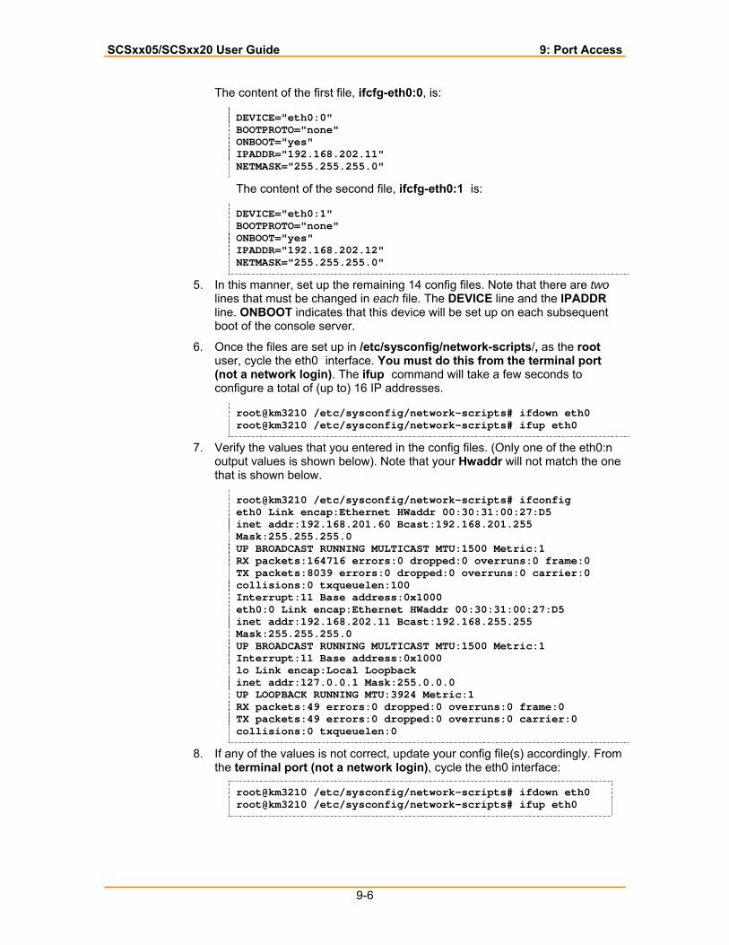
SCSxx05/SCSxx20 User Guide 9: Port Access
9-6
The content of the first file, ifcfg-eth0:0, is:
DEVICE="eth0:0" BOOTPROTO="none" ONBOOT="yes" IPADDR="192.168.202.11" NETMASK="255.255.255.0"
The content of the second file, ifcfg-eth0:1 is:
DEVICE="eth0:1" BOOTPROTO="none" ONBOOT="yes" IPADDR="192.168.202.12" NETMASK="255.255.255.0"
5. In this manner, set up the remaining 14 config files. Note that there are two lines that must be changed in each file. The DEVICE line and the IPADDR line. ONBOOT indicates that this device will be set up on each subsequent boot of the console server.
6. Once the files are set up in /etc/sysconfig/network-scripts/, as the root user, cycle the eth0 interface. You must do this from the terminal port (not a network login). The ifup command will take a few seconds to configure a total of (up to) 16 IP addresses.
root@km3210 /etc/sysconfig/network-scripts# ifdown eth0 root@km3210 /etc/sysconfig/network-scripts# ifup eth0
7. Verify the values that you entered in the config files. (Only one of the eth0:n output values is shown below). Note that your Hwaddr will not match the one that is shown below.
root@km3210 /etc/sysconfig/network-scripts# ifconfig eth0 Link encap:Ethernet HWaddr 00:30:31:00:27:D5 inet addr:192.168.201.60 Bcast:192.168.201.255 Mask:255.255.255.0 UP BROADCAST RUNNING MULTICAST MTU:1500 Metric:1 RX packets:164716 errors:0 dropped:0 overruns:0 frame:0 TX packets:8039 errors:0 dropped:0 overruns:0 carrier:0 collisions:0 txqueuelen:100 Interrupt:11 Base address:0x1000 eth0:0 Link encap:Ethernet HWaddr 00:30:31:00:27:D5 inet addr:192.168.202.11 Bcast:192.168.255.255 Mask:255.255.255.0 UP BROADCAST RUNNING MULTICAST MTU:1500 Metric:1 Interrupt:11 Base address:0x1000 lo Link encap:Local Loopback inet addr:127.0.0.1 Mask:255.0.0.0 UP LOOPBACK RUNNING MTU:3924 Metric:1 RX packets:49 errors:0 dropped:0 overruns:0 frame:0 TX packets:49 errors:0 dropped:0 overruns:0 carrier:0 collisions:0 txqueuelen:0
8. If any of the values is not correct, update your config file(s) accordingly. From the terminal port (not a network login), cycle the eth0 interface:
root@km3210 /etc/sysconfig/network-scripts# ifdown eth0 root@km3210 /etc/sysconfig/network-scripts# ifup eth0
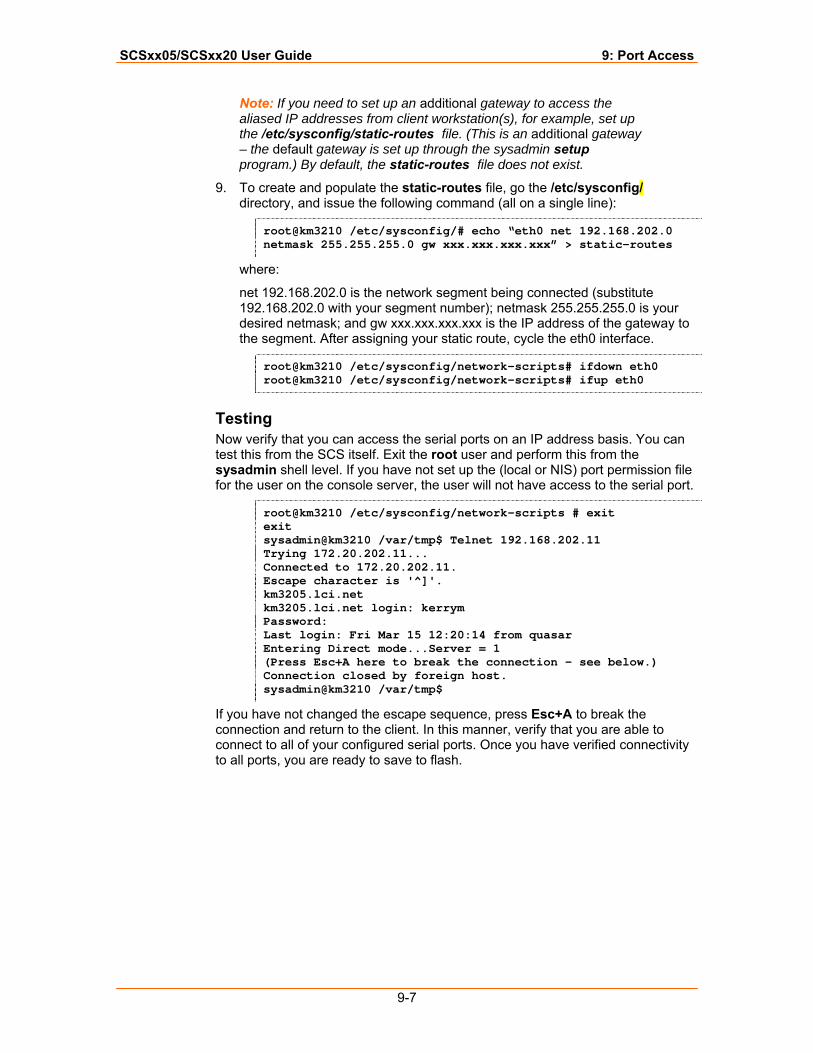
SCSxx05/SCSxx20 User Guide 9: Port Access
9-7
Note: If you need to set up an additional gateway to access the aliased IP addresses from client workstation(s), for example, set up the /etc/sysconfig/static-routes file. (This is an additional gateway – the default gateway is set up through the sysadmin setup program.) By default, the static-routes file does not exist.
9. To create and populate the static-routes file, go the /etc/sysconfig/ directory, and issue the following command (all on a single line):
root@km3210 /etc/sysconfig/# echo “eth0 net 192.168.202.0 netmask 255.255.255.0 gw xxx.xxx.xxx.xxx” > static-routes
where:
net 192.168.202.0 is the network segment being connected (substitute 192.168.202.0 with your segment number); netmask 255.255.255.0 is your desired netmask; and gw xxx.xxx.xxx.xxx is the IP address of the gateway to the segment. After assigning your static route, cycle the eth0 interface.
root@km3210 /etc/sysconfig/network-scripts# ifdown eth0 root@km3210 /etc/sysconfig/network-scripts# ifup eth0
Testing Now verify that you can access the serial ports on an IP address basis. You can test this from the SCS itself. Exit the root user and perform this from the sysadmin shell level. If you have not set up the (local or NIS) port permission file for the user on the console server, the user will not have access to the serial port.
root@km3210 /etc/sysconfig/network-scripts # exit exit sysadmin@km3210 /var/tmp$ Telnet 192.168.202.11 Trying 172.20.202.11... Connected to 172.20.202.11. Escape character is '^]'. km3205.lci.net km3205.lci.net login: kerrym Password: Last login: Fri Mar 15 12:20:14 from quasar Entering Direct mode...Server = 1 (Press Esc+A here to break the connection – see below.) Connection closed by foreign host. sysadmin@km3210 /var/tmp$
If you have not changed the escape sequence, press Esc+A to break the connection and return to the client. In this manner, verify that you are able to connect to all of your configured serial ports. Once you have verified connectivity to all ports, you are ready to save to flash.
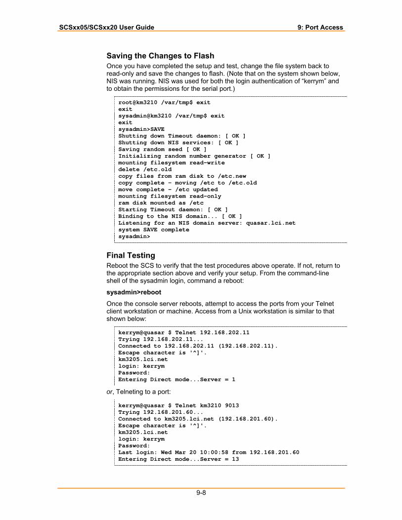
SCSxx05/SCSxx20 User Guide 9: Port Access
9-8
Saving the Changes to Flash Once you have completed the setup and test, change the file system back to read-only and save the changes to flash. (Note that on the system shown below, NIS was running. NIS was used for both the login authentication of “kerrym” and to obtain the permissions for the serial port.)
root@km3210 /var/tmp$ exit exit sysadmin@km3210 /var/tmp$ exit exit sysadmin>SAVE Shutting down Timeout daemon: [ OK ] Shutting down NIS services: [ OK ] Saving random seed [ OK ] Initializing random number generator [ OK ] mounting filesystem read-write delete /etc.old copy files from ram disk to /etc.new copy complete - moving /etc to /etc.old move complete - /etc updated mounting filesystem read-only ram disk mounted as /etc Starting Timeout daemon: [ OK ] Binding to the NIS domain... [ OK ] Listening for an NIS domain server: quasar.lci.net system SAVE complete sysadmin>
Final Testing Reboot the SCS to verify that the test procedures above operate. If not, return to the appropriate section above and verify your setup. From the command-line shell of the sysadmin login, command a reboot:
sysadmin>reboot
Once the console server reboots, attempt to access the ports from your Telnet client workstation or machine. Access from a Unix workstation is similar to that shown below:
kerrym@quasar $ Telnet 192.168.202.11 Trying 192.168.202.11... Connected to 192.168.202.11 (192.168.202.11). Escape character is '^]'. km3205.lci.net login: kerrym Password: Entering Direct mode...Server = 1
or, Telneting to a port:
kerrym@quasar $ Telnet km3210 9013 Trying 192.168.201.60... Connected to km3205.lci.net (192.168.201.60). Escape character is '^]'. km3205.lci.net login: kerrym Password: Last login: Wed Mar 20 10:00:58 from 192.168.201.60 Entering Direct mode...Server = 13
SCSxx05/SCSxx20 User Guide 9: Port Access
9-9
Bypassing Authentication Note: The ability to bypass the authentication mechanisms, as described below, may not be deployed on your particular console server. If it has been deployed on your console server and you have specified that authentication should not take place on certain serial ports, beware! Enable this feature only if the console server is located within a fully protected internal network, and all of the users can be trusted.
The console server requires each user of a serial port to be authenticated by the console server itself. The console server also requires each user who accesses the serial ports to have the proper direct, listen, and/or clear port permissions on a per port basis. This is the default operation. The authentication within the Linux login program is done using the Pluggable Authentication Module (PAM). This authentication module supports a wide variety of authentication types, for example, local password files, NIS, NIS+, LDAP, and Kerberos. The SCS supports the use of local password files, NIS, and LDAP.
On some console server systems, you can allow a Telnet connection directly to a serial port to bypass the authentication mechanism on the console server. This allows a client to connect directly to a serial port from anywhere on your network (segment). Of course, this can introduce security concerns. As a minimum, the device that is connected to the other end of the serial port should use some type of authentication method. Some sites may have their console servers on a dedicated internal network that only a system administrator (or a console management software application) can access. This additional step of authentication becomes either a nuisance or causes problems with the console management software application. In this case, you can indicate, on a port-by-port basis, that authentication not be done by the console server.
When you designate a serial port to have the console server authentication scheme bypassed, the appropriate sections of the login program are bypassed. Although the system never prompts the user for a username or password, the user automatically defaults to “nobody” on the console server.
To disable the authentication mechanism for directly connected serial ports, make two sets of changes.
1. Set a flag in the /lci/lwip_serial.conf file based on the specific serial port/IP/port number entry. The login process checks this file. A one (1) in the authentication column indicates that authentication must be done. A zero (0) indicates that authentication will not be done for this serial port/IP/port number entry.
Note: The authentication flag is specific to each serial port/IP/port number entry You can allow direct access to a serial port by an IP port number or by an assigned IP address. You may require authentication for serial ports accessed by assigned IP addresses and not require authentication for serial ports accessed by the IP port numbers. You can configure this; however, you can make only one direct connection to a serial port at a time.
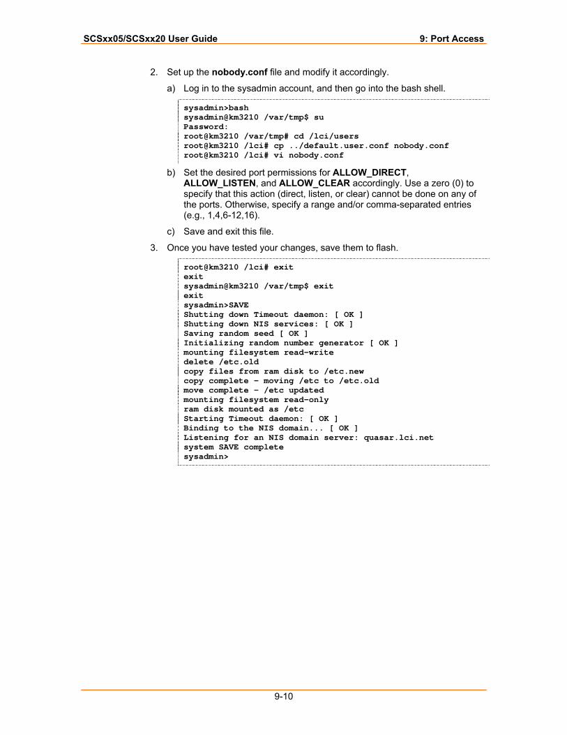
SCSxx05/SCSxx20 User Guide 9: Port Access
9-10
2. Set up the nobody.conf file and modify it accordingly.
a) Log in to the sysadmin account, and then go into the bash shell.
sysadmin>bash sysadmin@km3210 /var/tmp$ su Password: root@km3210 /var/tmp# cd /lci/users root@km3210 /lci# cp ../default.user.conf nobody.conf root@km3210 /lci# vi nobody.conf
b) Set the desired port permissions for ALLOW_DIRECT, ALLOW_LISTEN, and ALLOW_CLEAR accordingly. Use a zero (0) to specify that this action (direct, listen, or clear) cannot be done on any of the ports. Otherwise, specify a range and/or comma-separated entries (e.g., 1,4,6-12,16).
c) Save and exit this file.
3. Once you have tested your changes, save them to flash.
root@km3210 /lci# exit exit sysadmin@km3210 /var/tmp$ exit exit sysadmin>SAVE Shutting down Timeout daemon: [ OK ] Shutting down NIS services: [ OK ] Saving random seed [ OK ] Initializing random number generator [ OK ] mounting filesystem read-write delete /etc.old copy files from ram disk to /etc.new copy complete - moving /etc to /etc.old move complete - /etc updated mounting filesystem read-only ram disk mounted as /etc Starting Timeout daemon: [ OK ] Binding to the NIS domain... [ OK ] Listening for an NIS domain server: quasar.lci.net system SAVE complete sysadmin>
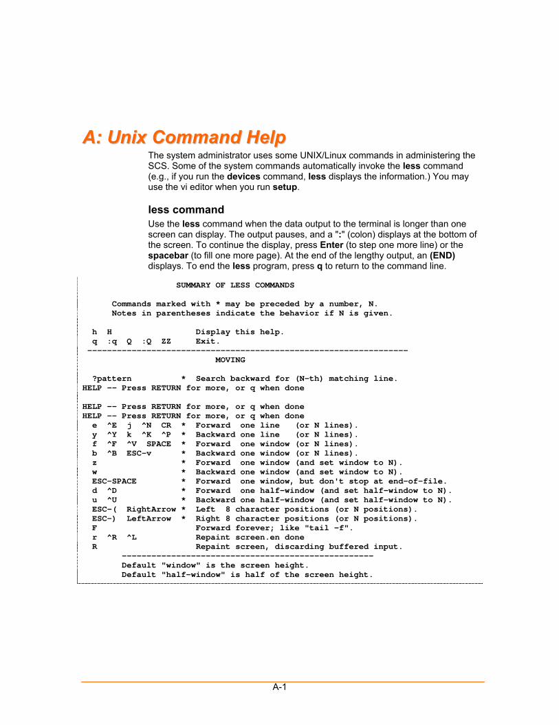
A-1
AA:: UUnniixx CCoommmmaanndd HHeellpp The system administrator uses some UNIX/Linux commands in administering the SCS. Some of the system commands automatically invoke the less command (e.g., if you run the devices command, less displays the information.) You may use the vi editor when you run setup.
less command Use the less command when the data output to the terminal is longer than one screen can display. The output pauses, and a ":" (colon) displays at the bottom of the screen. To continue the display, press Enter (to step one more line) or the spacebar (to fill one more page). At the end of the lengthy output, an (END) displays. To end the less program, press q to return to the command line.
SUMMARY OF LESS COMMANDS Commands marked with * may be preceded by a number, N. Notes in parentheses indicate the behavior if N is given. h H Display this help. q :q Q :Q ZZ Exit. ----------------------------------------------------------------- MOVING ?pattern * Search backward for (N-th) matching line. HELP -- Press RETURN for more, or q when done HELP -- Press RETURN for more, or q when done HELP -- Press RETURN for more, or q when done e ^E j ^N CR * Forward one line (or N lines). y ^Y k ^K ^P * Backward one line (or N lines). f ^F ^V SPACE * Forward one window (or N lines). b ^B ESC-v * Backward one window (or N lines). z * Forward one window (and set window to N). w * Backward one window (and set window to N). ESC-SPACE * Forward one window, but don't stop at end-of-file. d ^D * Forward one half-window (and set half-window to N). u ^U * Backward one half-window (and set half-window to N). ESC-( RightArrow * Left 8 character positions (or N positions). ESC-) LeftArrow * Right 8 character positions (or N positions). F Forward forever; like "tail -f". r ^R ^L Repaint screen.en done R Repaint screen, discarding buffered input. --------------------------------------------------- Default "window" is the screen height. Default "half-window" is half of the screen height.
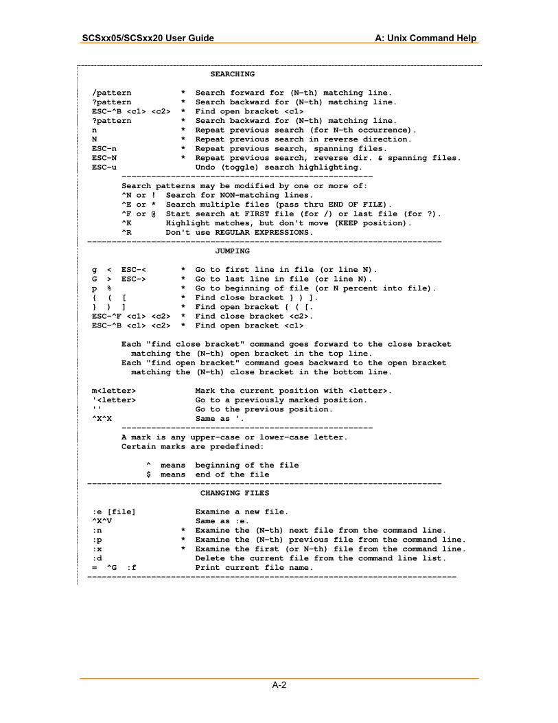
SCSxx05/SCSxx20 User Guide A: Unix Command Help
A-2
SEARCHING /pattern * Search forward for (N-th) matching line. ?pattern * Search backward for (N-th) matching line. ESC-^B <c1> <c2> * Find open bracket <c1> ?pattern * Search backward for (N-th) matching line. n * Repeat previous search (for N-th occurrence). N * Repeat previous search in reverse direction. ESC-n * Repeat previous search, spanning files. ESC-N * Repeat previous search, reverse dir. & spanning files. ESC-u Undo (toggle) search highlighting. --------------------------------------------------- Search patterns may be modified by one or more of: ^N or ! Search for NON-matching lines. ^E or * Search multiple files (pass thru END OF FILE). ^F or @ Start search at FIRST file (for /) or last file (for ?). ^K Highlight matches, but don't move (KEEP position). ^R Don't use REGULAR EXPRESSIONS. ------------------------------------------------------------------------ JUMPING g < ESC-< * Go to first line in file (or line N). G > ESC-> * Go to last line in file (or line N). p % * Go to beginning of file (or N percent into file). { ( [ * Find close bracket } ) ]. } ) ] * Find open bracket { ( [. ESC-^F <c1> <c2> * Find close bracket <c2>. ESC-^B <c1> <c2> * Find open bracket <c1> Each "find close bracket" command goes forward to the close bracket matching the (N-th) open bracket in the top line. Each "find open bracket" command goes backward to the open bracket matching the (N-th) close bracket in the bottom line. m<letter> Mark the current position with <letter>. '<letter> Go to a previously marked position. '' Go to the previous position. ^X^X Same as '. --------------------------------------------------- A mark is any upper-case or lower-case letter. Certain marks are predefined: ^ means beginning of the file $ means end of the file ------------------------------------------------------------------------ CHANGING FILES :e [file] Examine a new file. ^X^V Same as :e. :n * Examine the (N-th) next file from the command line. :p * Examine the (N-th) previous file from the command line. :x * Examine the first (or N-th) file from the command line. :d Delete the current file from the command line list. = ^G :f Print current file name. ---------------------------------------------------------------------------
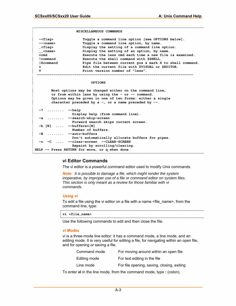
SCSxx05/SCSxx20 User Guide A: Unix Command Help
A-3
MISCELLANEOUS COMMANDS -<flag> Toggle a command line option [see OPTIONS below]. --<name> Toggle a command line option, by name. _<flag> Display the setting of a command line option. __<name> Display the setting of an option, by name. +cmd Execute the less cmd each time a new file is examined. !command Execute the shell command with $SHELL. |Xcommand Pipe file between current pos & mark X to shell command. v Edit the current file with $VISUAL or $EDITOR. V Print version number of "less". --------------------------------------------------------------------------- OPTIONS Most options may be changed either on the command line, or from within less by using the - or -- command. Options may be given in one of two forms: either a single character preceded by a -, or a name preceded by --. -? ........ --help Display help (from command line). -a ........ --search-skip-screen Forward search skips current screen. -b [N] .... --buffers=[N] Number of buffers. -B ........ --auto-buffers Don't automatically allocate buffers for pipes. -c -C .... --clear-screen --CLEAR-SCREEN Repaint by scrolling/clearing. HELP -- Press RETURN for more, or q when done
vi Editor Commands The vi editor is a powerful command editor used to modify Unix commands.
Note: It is possible to damage a file, which might render the system inoperative, by improper use of a file or command editor on system files. This section is only meant as a review for those familiar with vi commands.
Using vi To edit a file using the vi editor on a file with a name <file_name>, from the command line, type:
vi <file_name>
Use the following commands to edit and then close the file.
vi Modes vi is a three-mode line editor: it has a command mode, a line mode, and an editing mode. It is very useful for editing a file, for navigating within an open file, and for opening or saving a file.
Command mode For moving around within an open file
Editing mode For text editing in the file
Line mode For file opening, saving, closing, exiting
To enter vi in the line mode, from the command mode, type : (colon).
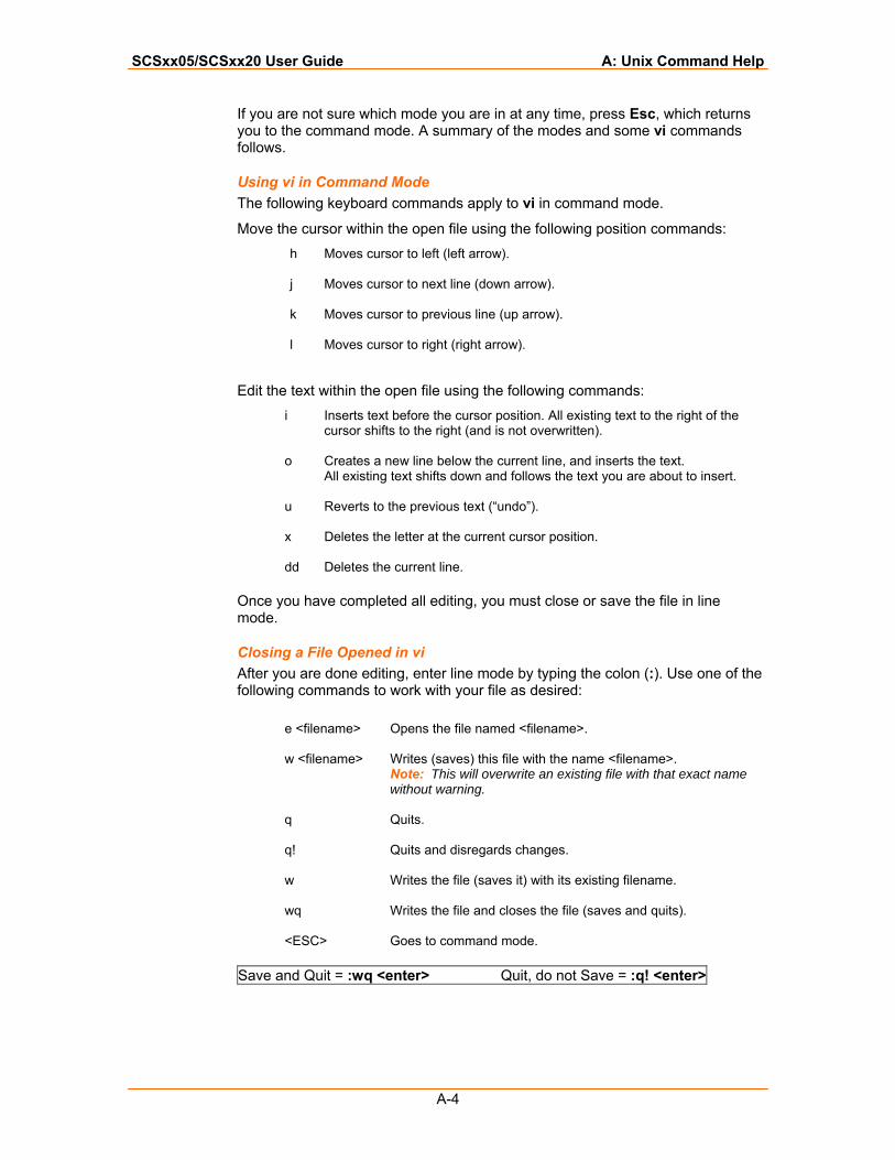
SCSxx05/SCSxx20 User Guide A: Unix Command Help
A-4
If you are not sure which mode you are in at any time, press Esc, which returns you to the command mode. A summary of the modes and some vi commands follows.
Using vi in Command Mode The following keyboard commands apply to vi in command mode.
Move the cursor within the open file using the following position commands: h Moves cursor to left (left arrow).
j Moves cursor to next line (down arrow).
k Moves cursor to previous line (up arrow).
l Moves cursor to right (right arrow).
Edit the text within the open file using the following commands: i Inserts text before the cursor position. All existing text to the right of the
cursor shifts to the right (and is not overwritten).
o Creates a new line below the current line, and inserts the text. All existing text shifts down and follows the text you are about to insert.
u Reverts to the previous text (“undo”).
x Deletes the letter at the current cursor position.
dd Deletes the current line.
Once you have completed all editing, you must close or save the file in line mode.
Closing a File Opened in vi After you are done editing, enter line mode by typing the colon (:). Use one of the following commands to work with your file as desired:
e <filename> Opens the file named <filename>.
w <filename> Writes (saves) this file with the name <filename>.
Note: This will overwrite an existing file with that exact name without warning.
q Quits.
q! Quits and disregards changes.
w Writes the file (saves it) with its existing filename.
wq Writes the file and closes the file (saves and quits).
<ESC> Goes to command mode.
Save and Quit = :wq <enter> Quit, do not Save = :q! <enter>

B-1
BB:: HHeexxaaddeecciimmaall CCoonnvveerrssiioonn CChhaarrtt Equivalent characters in italics are non-printing characters or signals.
Hexadecimal to Character Conversion
Hexadecimal Code
Equivalent Character Hexadecimal
Code Equivalent Character
00 NUL 20 SP 01 SOH 21 ! 02 STX 22 “ 03 ETX 23 # 04 EOT 24 $ 05 ENQ 25 % 06 ACK 26 & 07 BEL 27 ‘ 08 BS 28 ( 09 HT 29 ) 0A NL 2A * 0B VT 2B + 0C NP 2C , 0D CR 2D - 0E SO 2E . 0F SI 2F / 10 DLE 30 0 11 DC1 31 1 12 DC2 32 2 13 DC3 33 3 14 DC4 34 4 15 NAK 35 5 16 SYN 36 6 17 ETB 37 7 18 CAN 38 8 19 EM 39 9 1A SUB 3A : 1B ESC 3B ; 1C FS 3C < 1D GS 3D = 1E RS 3E > 1F US 3F ? 40 @ 60 ` 41 A 61 a
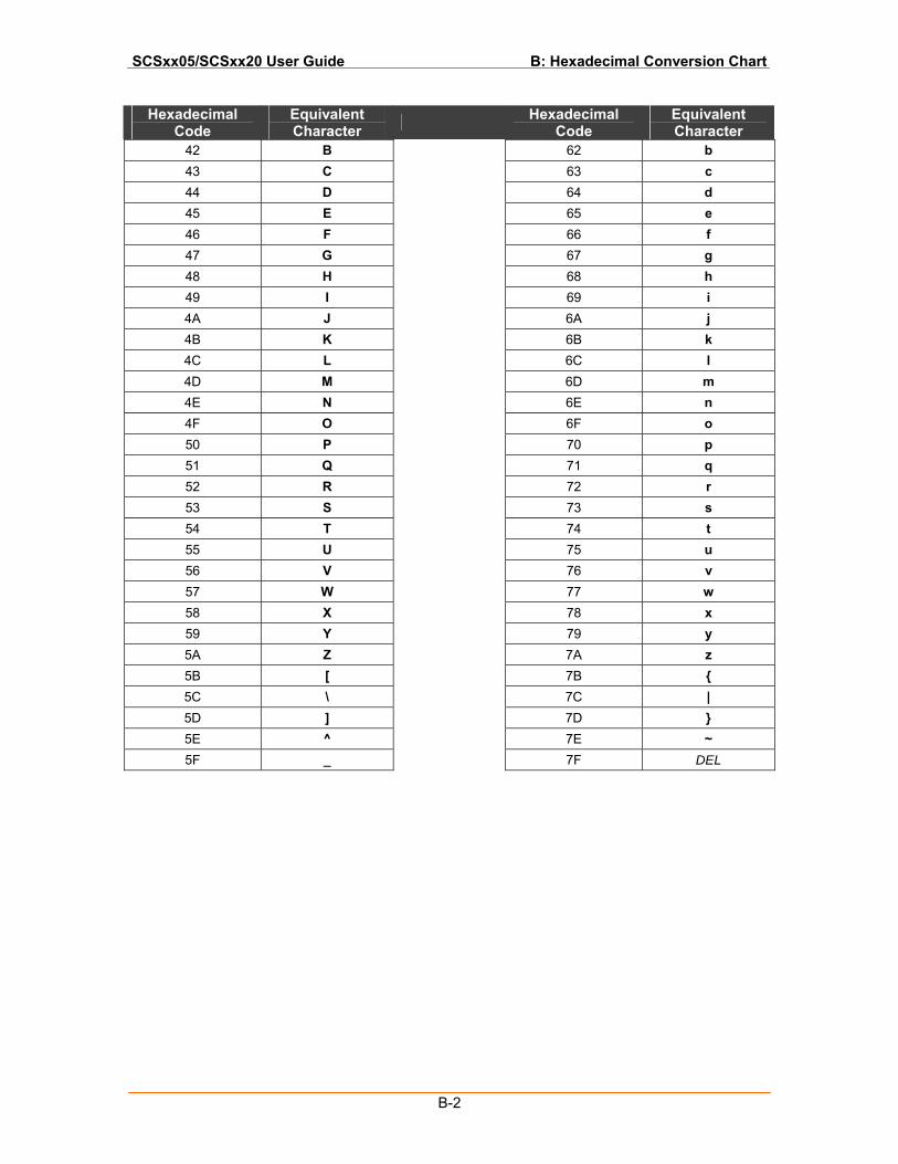
SCSxx05/SCSxx20 User Guide B: Hexadecimal Conversion Chart
B-2
Hexadecimal Code
Equivalent Character Hexadecimal
Code Equivalent Character
42 B 62 b 43 C 63 c 44 D 64 d 45 E 65 e 46 F 66 f 47 G 67 g 48 H 68 h 49 I 69 i 4A J 6A j 4B K 6B k 4C L 6C l 4D M 6D m 4E N 6E n 4F O 6F o 50 P 70 p 51 Q 71 q 52 R 72 r 53 S 73 s 54 T 74 t 55 U 75 u 56 V 76 v 57 W 77 w 58 X 78 x 59 Y 79 y 5A Z 7A z 5B [ 7B { 5C \ 7C | 5D ] 7D } 5E ^ 7E ~ 5F _ 7F DEL
C-1
The serial device ports of the SCSxx05/SCSxx20 products match the RJ45 pinouts of the console ports of many popular devices found in a network environment. The SCS uses conventional Category 5 fully pinned network cables for all connections; the cables are available from Lantronix in various lengths.
In some cases you will need an adaptor for your serial devices. Lantronix offers a variety of RJ45 to serial-connector adapters for many devices. These adapters convert the RJ45 connection on the SCS to a 9-pin or 25-pin serial connector found on some other manufacturer's serial devices.
You can configure the SCSxx05/SCSxx20 device ports as either DTE or DCE ports, using a software command, thus reducing the issues in making custom-pinned cables for different devices.
The serial terminal port is wired in the same manner as the device ports and has the same signal options.
Note: It is generally not necessary to change the configuration of the terminal port, other than its data rate. Therefore, no options are available on the setup menu or Web interface for changing its configuration. If you need to make a change, use the dtedce command to change DTE or DCE setting, and use the buttons on the front panel to change the baud rate (see Method #1 – Using the Front Panel Display in the Quick Start chapter).
CC:: PPiinnoouuttss aanndd AAddaapptteerrss
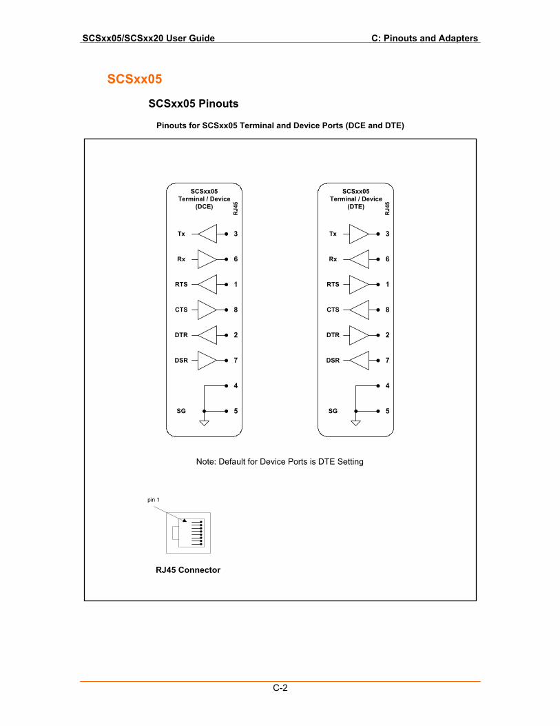
SCSxx05/SCSxx20 User Guide C: Pinouts and Adapters
C-2
SCSxx05
SCSxx05 Pinouts
Pinouts for SCSxx05 Terminal and Device Ports (DCE and DTE)
4
2
7
8
1
6
3
5
Tx
Rx
RTS
CTS
DTR
DSR
SG
SCSxx05Terminal / Device
(DTE)
RJ4
54
2
7
8
1
6
3
5
Tx
Rx
RTS
CTS
DTR
DSR
SG
SCSxx05Terminal / Device
(DCE)
RJ4
5
pin 1
RJ45 Connector
Note: Default for Device Ports is DTE Setting
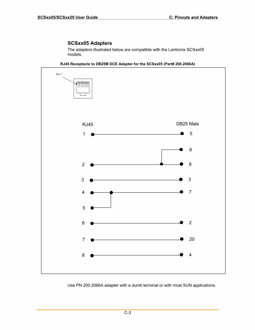
SCSxx05/SCSxx20 User Guide C: Pinouts and Adapters
C-3
SCSxx05 Adapters The adapters illustrated below are compatible with the Lantronix SCSxx05 models.
RJ45 Receptacle to DB25M DCE Adapter for the SCSxx05 (Part# 200.2066A)
Use PN 200.2066A adapter with a dumb terminal or with most SUN applications.
1 5
2 6
4 7
6 2
7 20
8 4
8
5
3 3
RJ45 DB25 Male
Pin 1
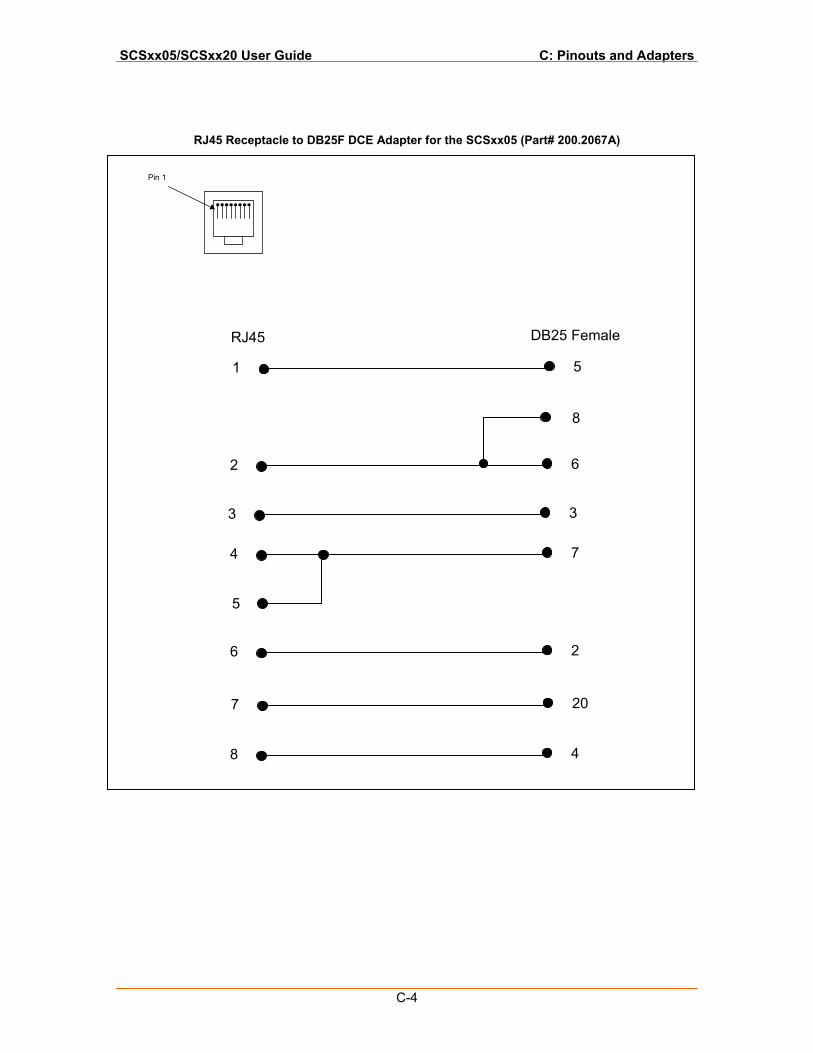
SCSxx05/SCSxx20 User Guide C: Pinouts and Adapters
C-4
RJ45 Receptacle to DB25F DCE Adapter for the SCSxx05 (Part# 200.2067A)
1 5
2 6
4 7
6 2
7 20
8 4
8
5
3 3
RJ45 DB25 Female
Pin 1
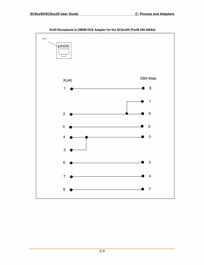
SCSxx05/SCSxx20 User Guide C: Pinouts and Adapters
C-5
RJ45 Receptacle to DB9M DCE Adapter for the SCSxx05 (Part# 200.2069A)
1 8
2 6
4 5
6 3
7 4
8 7
1
5
3 2
RJ45 DB9 Male
Pin 1
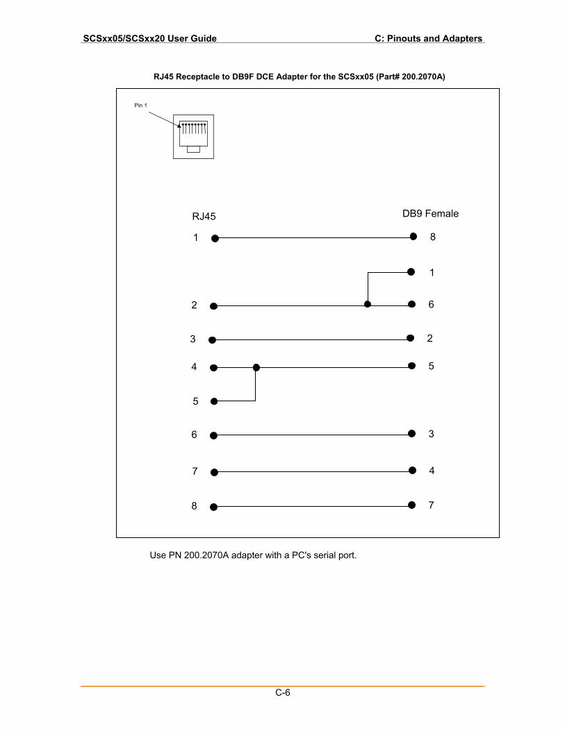
SCSxx05/SCSxx20 User Guide C: Pinouts and Adapters
C-6
RJ45 Receptacle to DB9F DCE Adapter for the SCSxx05 (Part# 200.2070A)
Use PN 200.2070A adapter with a PC's serial port.
1 8
2 6
4 5
6 3
7 4
8 7
1
5
3 2
RJ45 DB9 Female
Pin 1
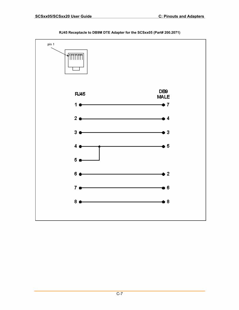
SCSxx05/SCSxx20 User Guide C: Pinouts and Adapters
C-7
RJ45 Receptacle to DB9M DTE Adapter for the SCSxx05 (Part# 200.2071)
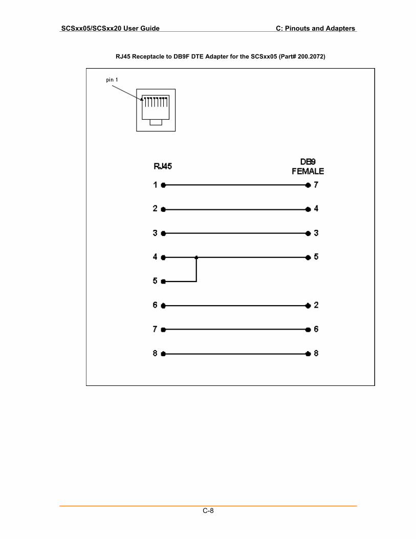
SCSxx05/SCSxx20 User Guide C: Pinouts and Adapters
C-8
RJ45 Receptacle to DB9F DTE Adapter for the SCSxx05 (Part# 200.2072)
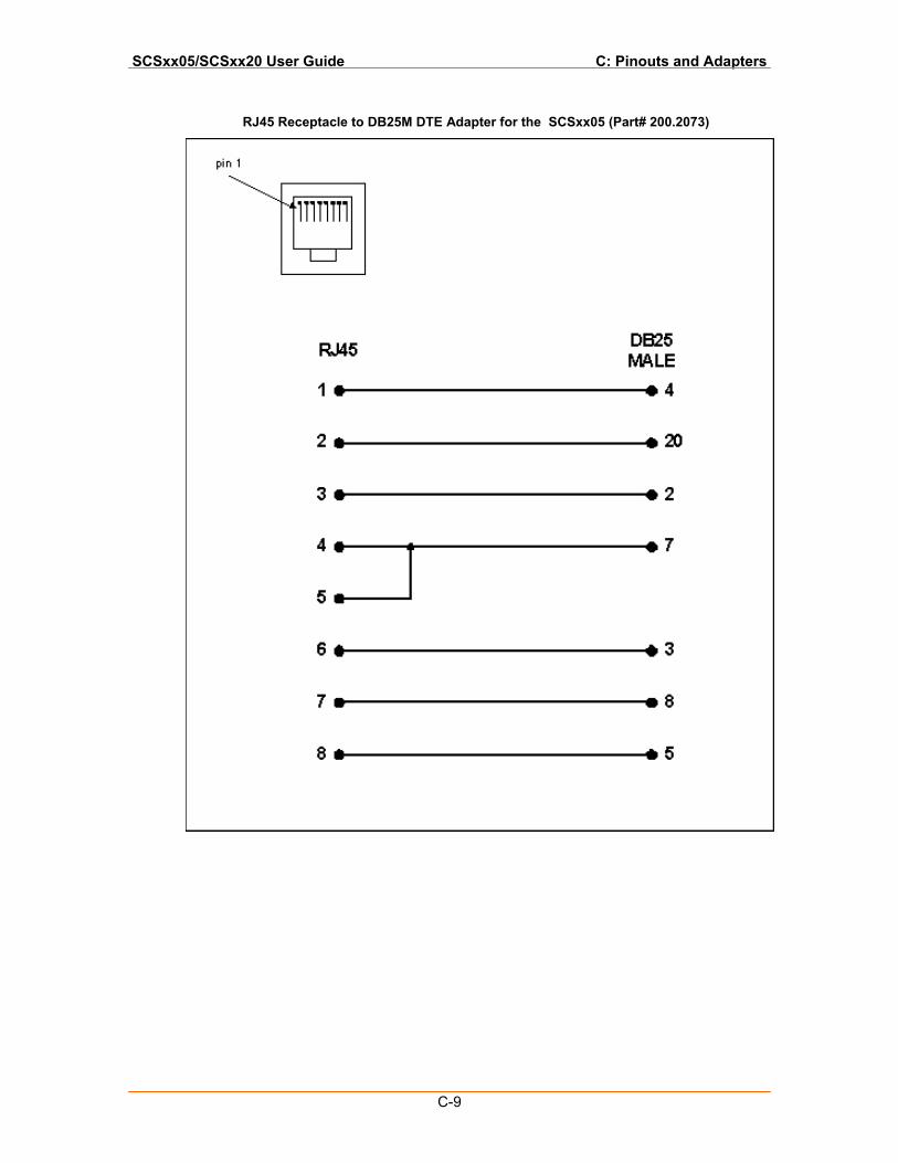
SCSxx05/SCSxx20 User Guide C: Pinouts and Adapters
C-9
RJ45 Receptacle to DB25M DTE Adapter for the SCSxx05 (Part# 200.2073)
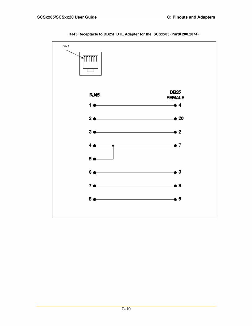
SCSxx05/SCSxx20 User Guide C: Pinouts and Adapters
C-10
RJ45 Receptacle to DB25F DTE Adapter for the SCSxx05 (Part# 200.2074)
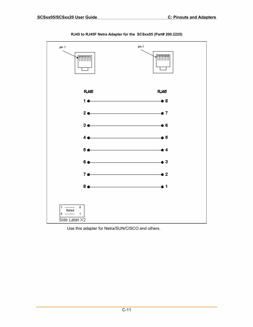
SCSxx05/SCSxx20 User Guide C: Pinouts and Adapters
C-11
RJ45 to RJ45F Netra Adapter for the SCSxx05 (Part# 200.2225)
Use this adapter for Netra/SUN/CISCO and others.
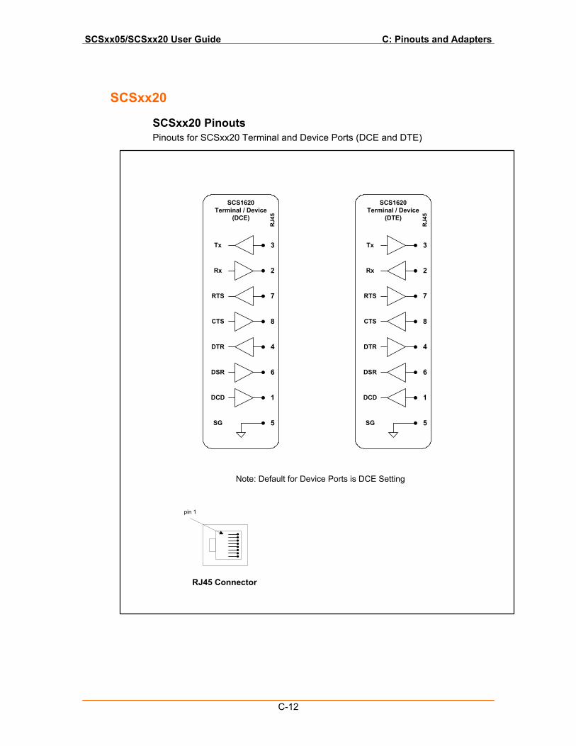
SCSxx05/SCSxx20 User Guide C: Pinouts and Adapters
C-12
SCSxx20
SCSxx20 Pinouts Pinouts for SCSxx20 Terminal and Device Ports (DCE and DTE)
1
4
6
8
7
2
3
5
Tx
Rx
RTS
CTS
DTR
DSR
DCD
SG
SCS1620Terminal / Device
(DTE)
RJ4
5
1
4
6
8
7
2
3
5
Tx
Rx
RTS
CTS
DTR
DSR
DCD
SG
SCS1620Terminal / Device
(DCE)
RJ4
5
pin 1
RJ45 Connector
Note: Default for Device Ports is DCE Setting
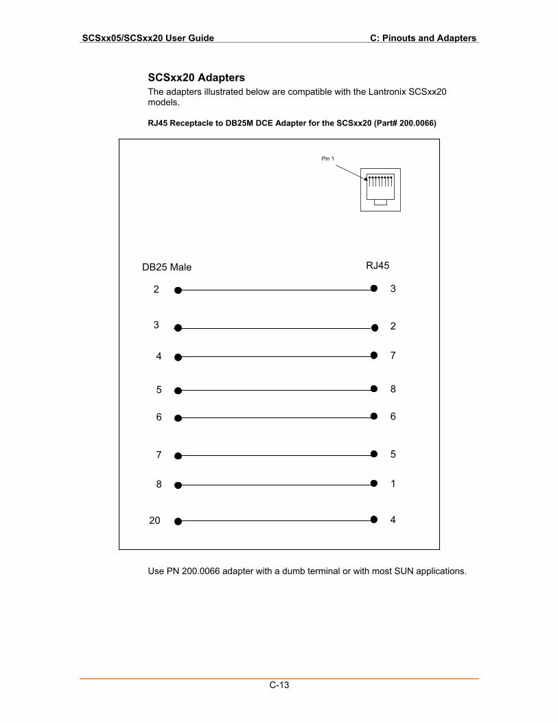
SCSxx05/SCSxx20 User Guide C: Pinouts and Adapters
C-13
SCSxx20 Adapters The adapters illustrated below are compatible with the Lantronix SCSxx20 models.
RJ45 Receptacle to DB25M DCE Adapter for the SCSxx20 (Part# 200.0066)
Use PN 200.0066 adapter with a dumb terminal or with most SUN applications.
2 3
4 7
6 6
8 1
20 4
5
5 8
DB25 Male RJ45
Pin 1
3 2
7 5
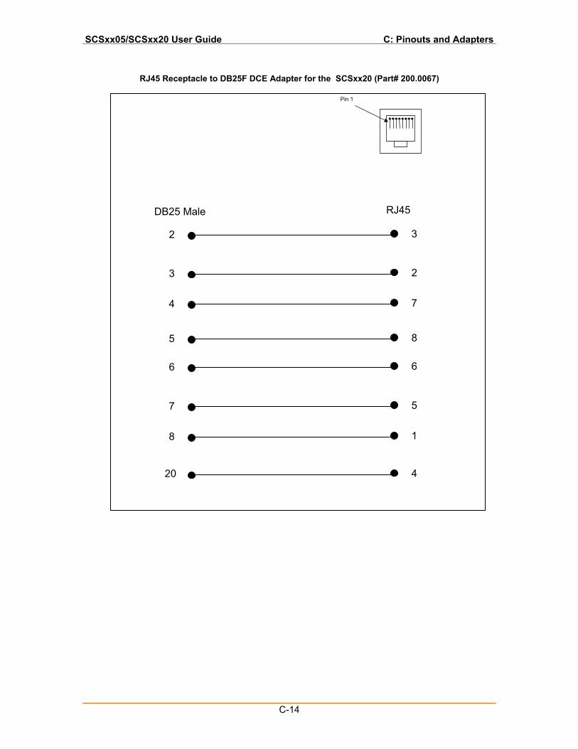
SCSxx05/SCSxx20 User Guide C: Pinouts and Adapters
C-14
RJ45 Receptacle to DB25F DCE Adapter for the SCSxx20 (Part# 200.0067)
2 3
4 7
6 6
8 1
20 4
1
5
5 8
DB25 Male RJ45
Pin 1
3 2
7 5
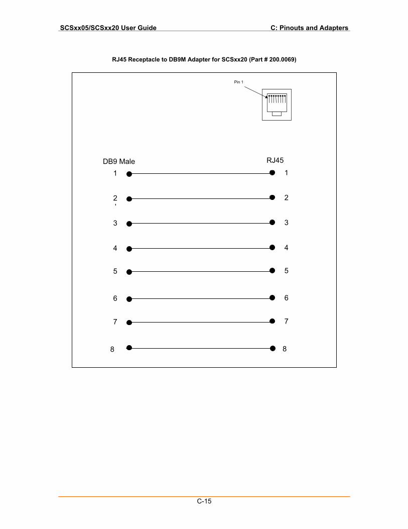
SCSxx05/SCSxx20 User Guide C: Pinouts and Adapters
C-15
RJ45 Receptacle to DB9M Adapter for SCSxx20 (Part # 200.0069)
1 1
3 3
5 5
7 7
8 8
1
5
4 4
DB9 Male RJ45
Pin 1
2 2
6 6
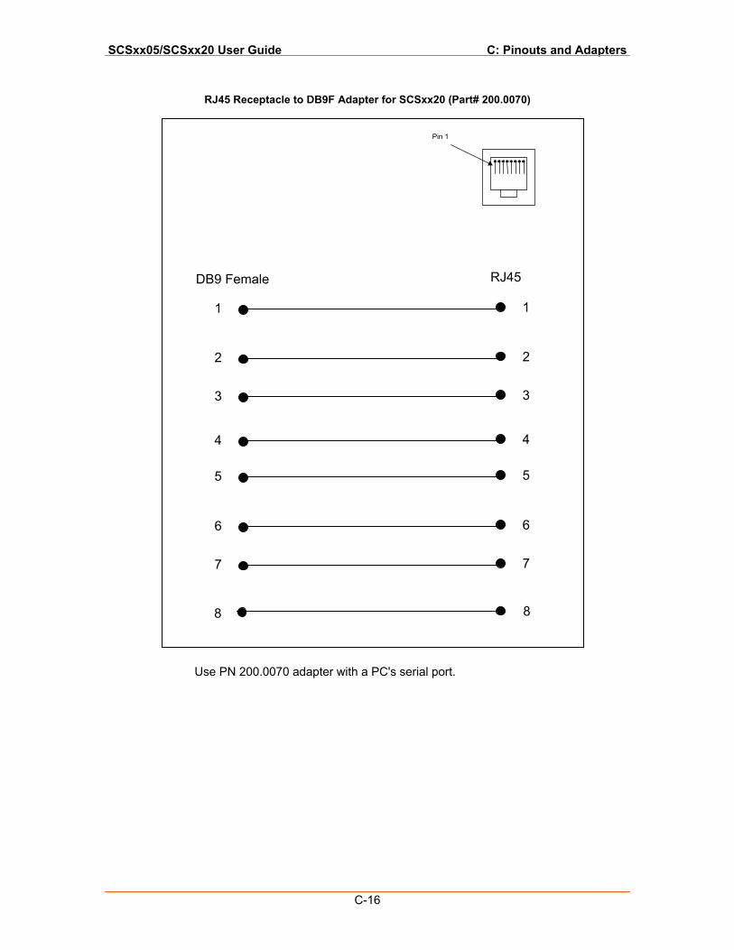
SCSxx05/SCSxx20 User Guide C: Pinouts and Adapters
C-16
RJ45 Receptacle to DB9F Adapter for SCSxx20 (Part# 200.0070)
Use PN 200.0070 adapter with a PC's serial port.
1 1
3 3
5 5
7 7
8 8
1
5
4 4
DB9 Female RJ45
Pin 1
2 2
6 6
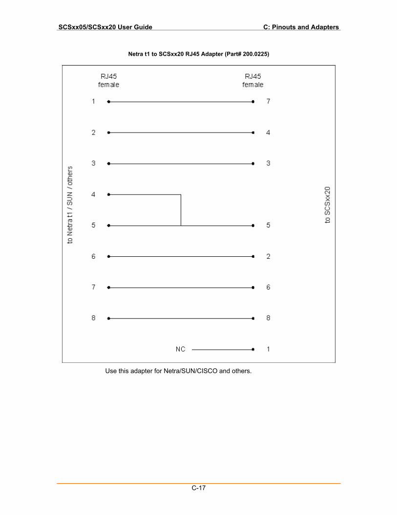
SCSxx05/SCSxx20 User Guide C: Pinouts and Adapters
C-17
Netra t1 to SCSxx20 RJ45 Adapter (Part# 200.0225)
Use this adapter for Netra/SUN/CISCO and others.
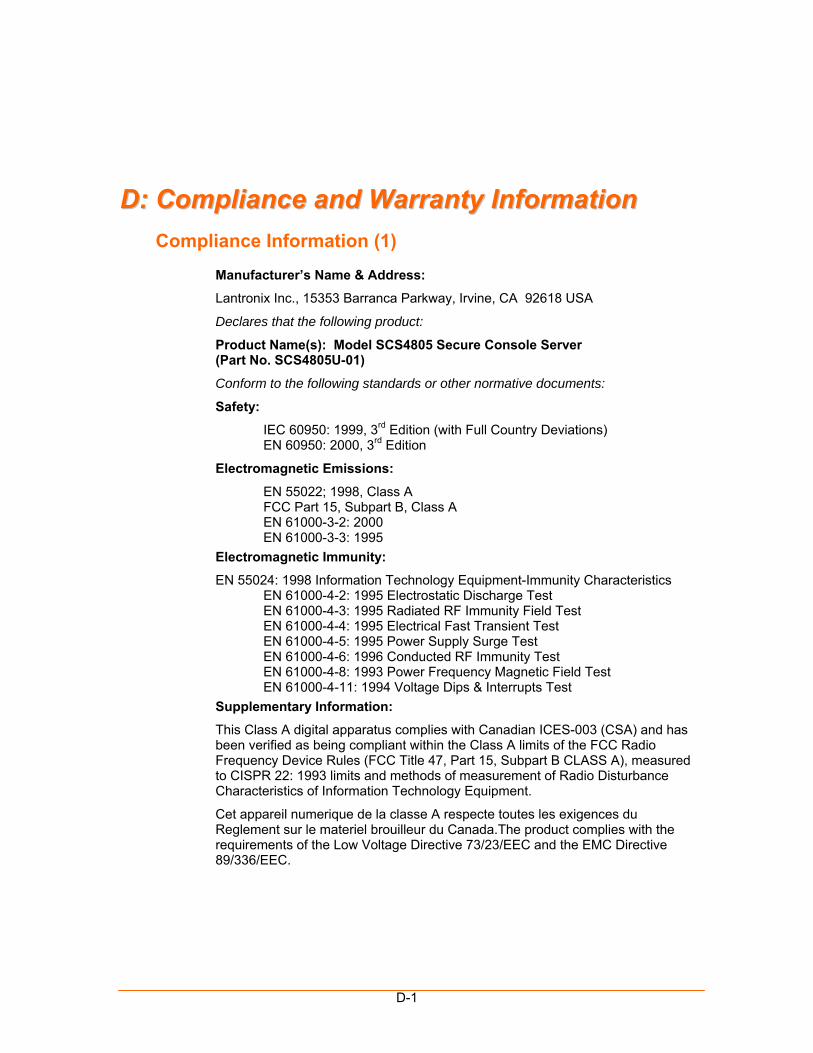
D-1
DD:: CCoommpplliiaannccee aanndd WWaarrrraannttyy IInnffoorrmmaattiioonn Compliance Information (1)
Manufacturer’s Name & Address:
Lantronix Inc., 15353 Barranca Parkway, Irvine, CA 92618 USA
Declares that the following product:
Product Name(s): Model SCS4805 Secure Console Server (Part No. SCS4805U-01)
Conform to the following standards or other normative documents:
Safety:
IEC 60950: 1999, 3rd Edition (with Full Country Deviations) EN 60950: 2000, 3rd Edition
Electromagnetic Emissions:
EN 55022; 1998, Class A FCC Part 15, Subpart B, Class A EN 61000-3-2: 2000 EN 61000-3-3: 1995 Electromagnetic Immunity:
EN 55024: 1998 Information Technology Equipment-Immunity Characteristics EN 61000-4-2: 1995 Electrostatic Discharge Test EN 61000-4-3: 1995 Radiated RF Immunity Field Test EN 61000-4-4: 1995 Electrical Fast Transient Test EN 61000-4-5: 1995 Power Supply Surge Test EN 61000-4-6: 1996 Conducted RF Immunity Test EN 61000-4-8: 1993 Power Frequency Magnetic Field Test EN 61000-4-11: 1994 Voltage Dips & Interrupts Test Supplementary Information:
This Class A digital apparatus complies with Canadian ICES-003 (CSA) and has been verified as being compliant within the Class A limits of the FCC Radio Frequency Device Rules (FCC Title 47, Part 15, Subpart B CLASS A), measured to CISPR 22: 1993 limits and methods of measurement of Radio Disturbance Characteristics of Information Technology Equipment.
Cet appareil numerique de la classe A respecte toutes les exigences du Reglement sur le materiel brouilleur du Canada.The product complies with the requirements of the Low Voltage Directive 73/23/EEC and the EMC Directive 89/336/EEC.
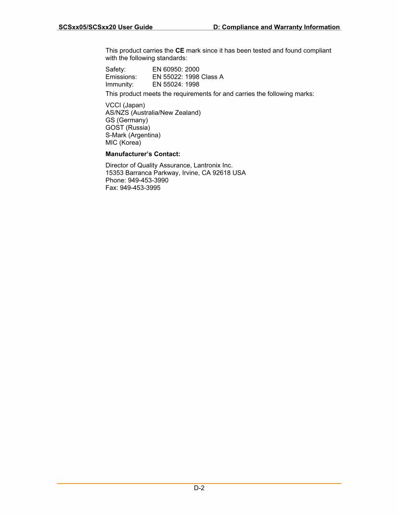
SCSxx05/SCSxx20 User Guide D: Compliance and Warranty Information
D-2
This product carries the CE mark since it has been tested and found compliant with the following standards:
Safety: EN 60950: 2000 Emissions: EN 55022: 1998 Class A Immunity: EN 55024: 1998 This product meets the requirements for and carries the following marks:
VCCI (Japan) AS/NZS (Australia/New Zealand) GS (Germany) GOST (Russia) S-Mark (Argentina) MIC (Korea)
Manufacturer’s Contact:
Director of Quality Assurance, Lantronix Inc. 15353 Barranca Parkway, Irvine, CA 92618 USA Phone: 949-453-3990 Fax: 949-453-3995
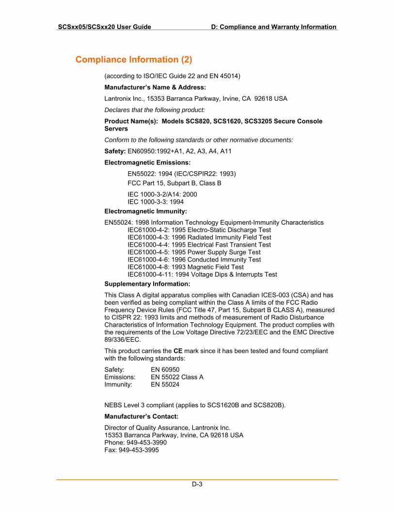
SCSxx05/SCSxx20 User Guide D: Compliance and Warranty Information
D-3
Compliance Information (2)
(according to ISO/IEC Guide 22 and EN 45014)
Manufacturer’s Name & Address:
Lantronix Inc., 15353 Barranca Parkway, Irvine, CA 92618 USA
Declares that the following product:
Product Name(s): Models SCS820, SCS1620, SCS3205 Secure Console Servers
Conform to the following standards or other normative documents:
Safety: EN60950:1992+A1, A2, A3, A4, A11
Electromagnetic Emissions:
EN55022: 1994 (IEC/CSPIR22: 1993) FCC Part 15, Subpart B, Class B
IEC 1000-3-2/A14: 2000 IEC 1000-3-3: 1994 Electromagnetic Immunity:
EN55024: 1998 Information Technology Equipment-Immunity Characteristics IEC61000-4-2: 1995 Electro-Static Discharge Test IEC61000-4-3: 1996 Radiated Immunity Field Test IEC61000-4-4: 1995 Electrical Fast Transient Test IEC61000-4-5: 1995 Power Supply Surge Test IEC61000-4-6: 1996 Conducted Immunity Test IEC61000-4-8: 1993 Magnetic Field Test IEC61000-4-11: 1994 Voltage Dips & Interrupts Test Supplementary Information:
This Class A digital apparatus complies with Canadian ICES-003 (CSA) and has been verified as being compliant within the Class A limits of the FCC Radio Frequency Device Rules (FCC Title 47, Part 15, Subpart B CLASS A), measured to CISPR 22: 1993 limits and methods of measurement of Radio Disturbance Characteristics of Information Technology Equipment. The product complies with the requirements of the Low Voltage Directive 72/23/EEC and the EMC Directive 89/336/EEC.
This product carries the CE mark since it has been tested and found compliant with the following standards:
Safety: EN 60950 Emissions: EN 55022 Class A Immunity: EN 55024
NEBS Level 3 compliant (applies to SCS1620B and SCS820B).
Manufacturer’s Contact:
Director of Quality Assurance, Lantronix Inc. 15353 Barranca Parkway, Irvine, CA 92618 USA Phone: 949-453-3990 Fax: 949-453-3995

SCSxx05/SCSxx20 User Guide D: Compliance and Warranty Information
D-4
Warranty
Lantronix warrants each Lantronix product to be free from defects in material and workmanship for a period of ONE YEAR after the date of shipment. During this period, if a customer is unable to resolve a product problem with Lantronix Technical Support, a Return Material Authorization (RMA) will be issued. Following receipt of an RMA number, the customer shall return the product to Lantronix, freight prepaid. Upon verification of warranty, Lantronix will -- at its option -- repair or replace the product and return it to the customer freight prepaid. If the product is not under warranty, the customer may have Lantronix repair the unit on a fee basis or return it. No services are handled at the customer's site under this warranty. This warranty is voided if the customer uses the product in an unauthorized or improper way, or in an environment for which it was not designed.
Lantronix warrants the media containing its software product to be free from defects and warrants that the software will operate substantially according to Lantronix specifications for a period of 60 DAYS after the date of shipment. The customer will ship defective media to Lantronix. Lantronix will ship the replacement media to the customer.
* * * *
In no event will Lantronix be responsible to the user in contract, in tort (including negligence), strict liability or otherwise for any special, indirect, incidental or consequential damage or loss of equipment, plant or power system, cost of capital, loss of profits or revenues, cost of replacement power, additional expenses in the use of existing software, hardware, equipment or facilities, or claims against the user by its employees or customers resulting from the use of the information, recommendations, descriptions and safety notations supplied by Lantronix. Lantronix liability is limited (at its election) to:
Refund of buyer's purchase price for such affected products (without interest)
Repair or replacement of such products, provided that the buyer follows the above procedures.
There are no understandings, agreements, representations or warranties, express or implied, including warranties of merchantability or fitness for a particular purpose, other than those specifically set out above or by any existing contract between the parties. Any such contract states the entire obligation of Lantronix. The contents of this document shall not become part of or modify any prior or existing agreement, commitment, or relationship.
For details on the Lantronix warranty replacement policy, go to our web site at http://www.lantronix.com/support/warranty/index.html