Embed Size (px)
Citation preview
Copyright © 2020 Aryaka Networks, Inc. All Rights Reserved
SD-WAN Architectures ExplainedDesign considerations for WAN 2.0A comparison of different SD-WAN architecturesincluding Cisco, VMware, AT&T, and others.Overlays vs underlays, public vs private, MPLS, ease of deployment, and performance.

SD-WAN Architectures Explained (For external use) 2 [email protected] | +1.877.727.9252
Table of Contents1. Introduction
2. Why is the Network Architecture Important?
3. Right Network Architecture = Right Kind of Application Performance
4. Understanding the Basic Fabrics: Public vs Private
5. �e Traditional Internet
6. Multiprotocol Label Switching
7. SD-WAN: �e Next Chapter
8. Which is the Right One For You?
9. Aryaka: Fly Business Class Over the Middle-Mile
10. Litmus Test
11. Litmus Test Results
12. �e Aryaka Difference
13. Conclusions
3
4
4-5
5
6-8
9-10
11-12
12-14
14-17
18-26
27
28
29
SD-WAN Architectures Explained (For external use) [email protected] | +1.877.727.9252
IntroductionAs the IT infrastructure leaps from legacy and siloed to cloud-first and integrated,user expectations of subscriber-specific services are rising. To keep the operationscrisp requires seamless integration between multi-disciplinary devices & nodes, andend-to-end orchestration of the network in which they reside. �is is precisely whatmakes the network architecture indispensable to application performance and apredictable user experience.
In fact, it wouldn’t be wrong to say that evolution is to biology as the architecture isto networking. You adapt, learn and improve. �ink of it as a map to your digitaltransformation initiatives that connects a global user base, applications andcloud services. �e importance of getting it right is only becoming more critical fordriving higher ROI and engagement.
Network architectures can vary significantly in terms of performance, complexity, security, and efficiency. Take, for instance, the so�ware-centric approach over the traditional WAN deployment. It deploys faster, scales immediately, reduces capital expenditure, and simplifies network operations. Having said that, there are numerous ways of delivering these so�ware-centric benefits, and they do not guarantee the same level of performance, cost savings, capability, or user experience.
Considering the plethora of available choices, it can be difficult as a CIO to separate the wheat from the chaff. �is technology primer explores the limitations, properties and modus operandi of different network mediums, architectures and SD-WAN solutions. Further, we compare Aryaka’s global SD-WAN as-a-Service to MPLS and other traditional SD-WAN deployment approaches.
SD-WAN Architectures Explained (For external use) [email protected] | +1.877.727.9252
Enterprise networks carry a varied range of traffic, such as video, voice, and data. Each one of these traffic classes has its own set of performance requirements and traffic characteristics. A wisely carved out network framework places the right elements to facilitate sufficient resources to each traffic class in order to guarantee the required quality-of-service (QoS) and incremental performance improvements.
A Hybrid WAN architecture for example, combines broadband and MPLS, allowing network managers to keep mission critical traffic on the MPLS network and offload best effort traffic like e-mail and remote backups. �is is certainly a better use of bandwidth than running everything over the MPLS network.
An optimal network architecture ensures you have the right technology placed at the right spot, so as to extract the maximum application performance benefits from them. Consider WAN aggregation and multi-path technologies, for instance. �ey enable dual links to be used simultaneously — a significant improvement over the traditional bandwidth
Why is the Network Architecture Important?No network engineer wants to be responsible for network issues that can be attributed to improper device configurations, hardware failures, routing issues or security flaws. Especially when businesses are shelling out a fortune to get it right.
How you choose to architect your network is crucial for more reasons than we can count. Not only is it vital in determining how well your network functions, but it also makes it easier to detect and troubleshoot errors as well as allocate resources more efficiently to ensure optimum network health and performance. From a ROI perspective, selecting the right network architecture can increase energy and data efficiency, which in turn, reduces operational and maintenance costs.
Furthermore, most networks can address a particular set of applications like real-time or cloud but it’s important to optimize all applications, and how you choose to architect your network has a pivotal role to play in it.
Network Health Performance Error Detection Effective Utilization
Right Network Architecture = Right Kind of Application Performance
SD-WAN Architectures Explained (For external use) [email protected] | +1.877.727.9252
wasting, overly expensive active-passive model of using multiple connections. Effectively, this technology creates one big link from multiple small ones. WAN Optimization is another technology that does a fantastic job of optimizing the performance of applications like e-mail and Windows file services over private networks.
�e bottomline? Choosing the right architecture is a critical consideration when engineering your network backbone for optimum application performance.
�e network foundation on which data and applications are delivered can broadly be classified into two groups — Public & Private.
A public network is a network available to everyone, inexpensive and widely available. Consider the internet for example, a large-scale public network which houses billions of devices and websites. �e affordability of the internet makes it an attractive option for reducing bandwidth costs. However, there is more to it than meets the eye. We will save that discussion for the next chapter.
Understanding the Basic Fabrics: Public vs Private
A private network on the other hand is a network with restricted access, or more tightly controlled, so to say. Only a selected set of devices can access it, depending on the settings encoded in the network routers and access points. MPLS would be a close example, more secure, guaranteed performance and availability, however, a bit he�y on the pocket.
If your organization has an SD-WAN rollout on the cards, you will eventually end up using one of these, or probably both as the underlay. And, we cannot stress enough, how regardless of all the fancy experiments in the overlay, it is the underlay that your applications performance and data rides upon. Let’s take a quick look at how they work, limitations and the best way forward.
SD-WAN Architectures Explained (For external use) [email protected] | +1.877.727.9252
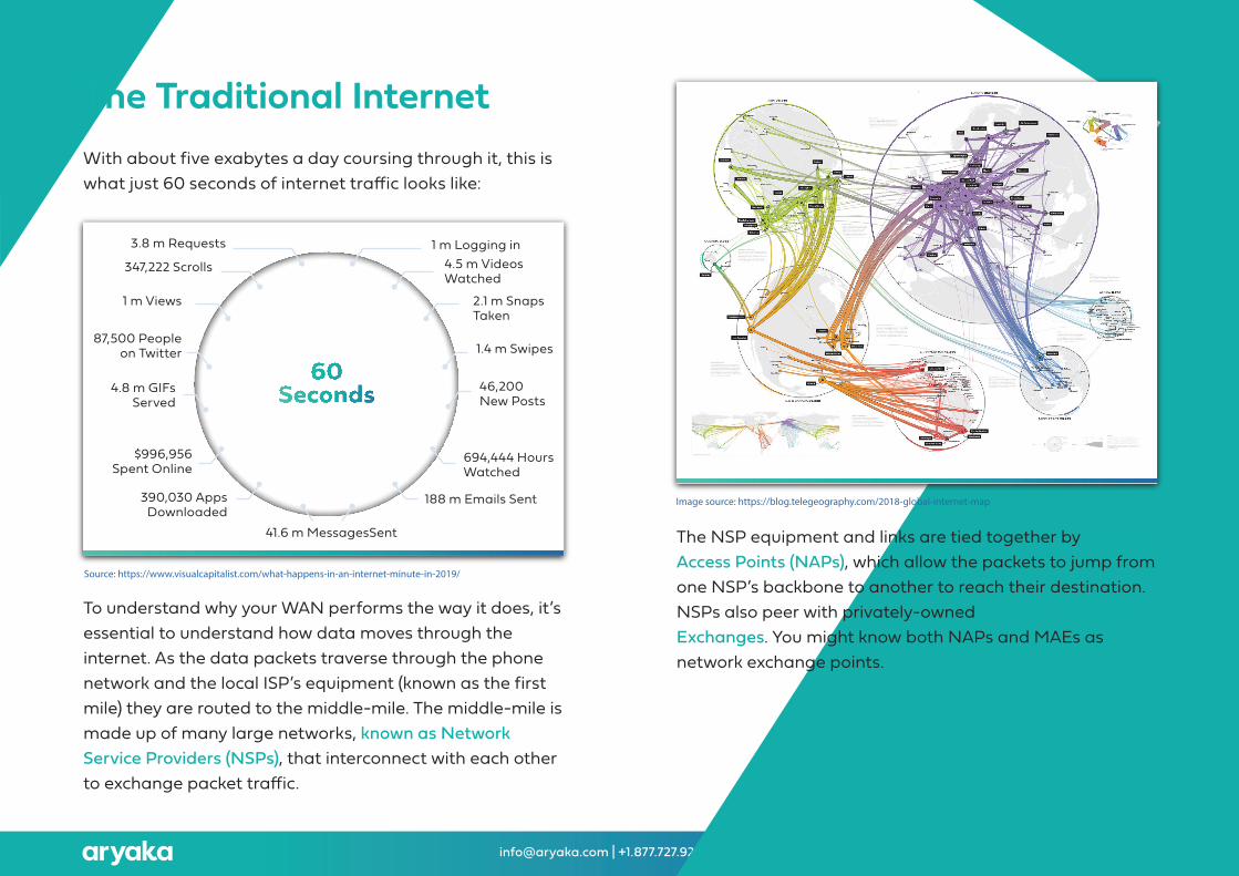
�e Traditional InternetWith about five exabytes a day coursing through it, this is what just 60 seconds of internet traffic looks like:
To understand why your WAN performs the way it does, it’s essential to understand how data moves through the internet. As the data packets traverse through the phone network and the local ISP’s equipment (known as the first mile) they are routed to the middle-mile. �e middle-mile is made up of many large networks, known as Network Service Providers (NSPs), that interconnect with each other to exchange packet traffic.
�e NSP equipment and links are tied together by Network Access Points (NAPs), which allow the packets to jump from one NSP’s backbone to another to reach their destination. NSPs also peer with privately-owned Metropolitan Area Exchanges. You might know both NAPs and MAEs as network exchange points.
Image source: https://blog.telegeography.com/2018-global-internet-map
1 m Logging in4.5 m Videos Watched
2.1 m Snaps Taken
1.4 m Swipes
46,200 New Posts
694,444 HoursWatched
188 m Emails Sent390,030 AppsDownloaded
$996,956Spent Online
4.8 m GIFsServed
87,500 Peopleon Twitter
1 m Views
347,222 Scrolls
3.8 m Requests
41.6 m MessagesSent
Source: https://www.visualcapitalist.com/what-happens-in-an-internet-minute-in-2019/
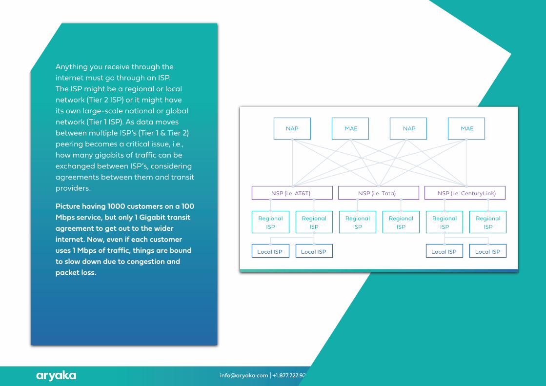
Anything you receive through the internet must go through an ISP. �e ISP might be a regional or local network (Tier 2 ISP) or it might have its own large-scale national or global network (Tier 1 ISP). As data moves between multiple ISP’s (Tier 1 & Tier 2) peering becomes a critical issue, i.e., how many gigabits of traffic can be exchanged between ISP’s, considering agreements between them and transit providers.
Picture having 1000 customers on a 100 Mbps service, but only 1 Gigabit transit agreement to get out to the wider internet. Now, even if each customer uses 1 Mbps of traffic, things are bound to slow down due to congestion and packet loss.
SD-WAN Architectures Explained (For external use) [email protected] | +1.877.727.9252
Local ISP
NSP (i.e. AT&T) NSP (i.e. Tata) NSP (i.e. CenturyLink)
RegionalISP
RegionalISP
RegionalISP
RegionalISP
RegionalISP
RegionalISP
Local ISP Local ISP Local ISP
NAP MAE NAP MAE
SD-WAN Architectures Explained (For external use) [email protected] | +1.877.727.9252
Observations�e internet cannot provide the resiliency, security and reliability that comes with dedicated private links. �e congested middle-mile, being the breeding ground for unreliable latency, leaves the end-to-end network performance to luck and to the laws of probability.
Users generally might not get affected by the latency itself, but the effect it has on application performance. Real-time applications that respond well on local network witness performance depletion when deployed on a wide area network once distance is introduced.
�e longer the distance, the additional carrier interconnects, greater propagation delay, and additional routing, switching, queuing, and buffering. While latency cannot be reduced to zero, the above-said factors bump up the variability in latency. With greater unpredictability and the range of variation in latency, real-time applications will experience more packet loss and performance degradation.
SD-WAN Architectures Explained (For external use) [email protected] | +1.877.727.9252
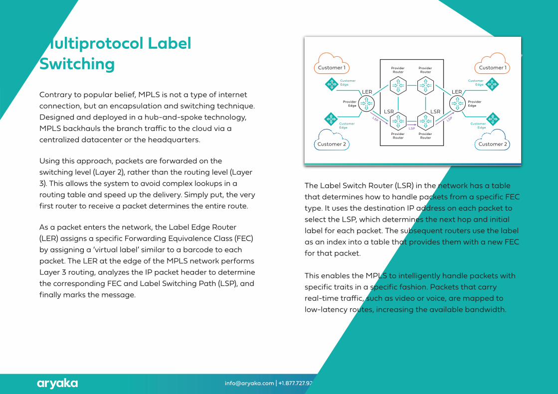
Multiprotocol Label SwitchingContrary to popular belief, MPLS is not a type of internet connection, but an encapsulation and switching technique. Designed and deployed in a hub-and-spoke technology, MPLS backhauls the branch traffic to the cloud via a centralized datacenter or the headquarters.
Using this approach, packets are forwarded on the switching level (Layer 2), rather than the routing level (Layer 3). �is allows the system to avoid complex lookups in a routing table and speed up the delivery. Simply put, the very first router to receive a packet determines the entire route.
As a packet enters the network, the Label Edge Router (LER) assigns a specific Forwarding Equivalence Class (FEC) by assigning a ‘virtual label’ similar to a barcode to each packet. �e LER at the edge of the MPLS network performs Layer 3 routing, analyzes the IP packet header to determine the corresponding FEC and Label Switching Path (LSP), and finally marks the message.
�e Label Switch Router (LSR) in the network has a table that determines how to handle packets from a specific FEC type. It uses the destination IP address on each packet to select the LSP, which determines the next hop and initial label for each packet. �e subsequent routers use the label as an index into a table that provides them with a new FEC for that packet.
�is enables the MPLS to intelligently handle packets with specific traits in a specific fashion. Packets that carry real-time traffic, such as video or voice, are mapped to low-latency routes, increasing the available bandwidth.
Customer 1
Customer 2
CustomerEdge
LSPCustomerEdge
ProviderEdge
LER
Customer 1
Customer 2
CustomerEdge
CustomerEdge
ProviderEdge
LER
Provider Router
Provider Router
Provider Router
Provider Router
LSR LSRLSP
LSP
SD-WAN Architectures Explained (For external use) [email protected] | +1.877.727.9252
Since the advent of cloud computing, enterprises are witnessing a huge surge in their WAN traffic. MPLS is ill-equipped to handle either of these trends — a consistent growth of WAN traffic means that enterprises must continually invest in expensive and difficult-to-scale bandwidth, and the continued shi� to cloud-based traffic means that WAN managers are now tasked with backhauling and managing expensive hardware for optimization and acceleration. �is is because MPLS needs to be topped-up with WAN optimization appliances at each end to make real application performance improvements. Deploying these devices in your own corporate datacenter is one thing, but deploying them in a cloud or a SaaS application provider’s location is quite another, o�en resulting in long deployment timelines and a he�y price tag.
When MPLS first launched, cloud platforms and SaaS applications weren’t even on the horizon. It was primarily designed to address packet loss and latency. While it might have been useful and groundbreaking in its time, evidence continues to mount that it can no longer serve the needs of today’s global enterprises.
Observations
SD-WAN Architectures Explained (For external use) [email protected] | +1.877.727.9252
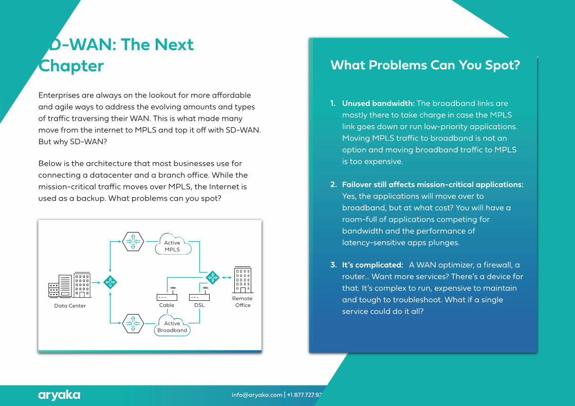
What Problems Can You Spot?
1. Unused bandwidth: �e broadband links are mostly there to take charge in case the MPLS link goes down or run low-priority applications. Moving MPLS traffic to broadband is not an option and moving broadband traffic to MPLS is too expensive.
2. Failover still affects mission-critical applications: Yes, the applications will move over to broadband, but at what cost? You will have a room-full of applications competing for bandwidth and the performance of latency-sensitive apps plunges.
3. It’s complicated: A WAN optimizer, a firewall, a router… Want more services? �ere’s a device for that. It’s complex to run, expensive to maintain and tough to troubleshoot. What if a single service could do it all?
SD-WAN: �e Next ChapterEnterprises are always on the lookout for more affordable and agile ways to address the evolving amounts and types of traffic traversing their WAN. �is is what made many move from the internet to MPLS and top it off with SD-WAN. But why SD-WAN?
Below is the architecture that most businesses use for connecting a datacenter and a branch office. While the mission-critical traffic moves over MPLS, the Internet is used as a backup. What problems can you spot?
Data CenterRemote
OfficeCable DSL
ActiveMPLS
ActiveBroadband
SD-WAN Architectures Explained (For external use) [email protected] | +1.877.727.9252
4. Network administration = Nightmare: Take the above topology and add ten more branch offices to it. Add a few cloud services as well. What you are looking at is a network manager’s nightmare. Each path needs different configurations for the application traffic and many parts of the organization may require customized configurations as well.
�ese challenges are just the tip of the iceberg, explaining why it makes sense for the enterprises to turn to SD-WAN. Gartner predicts the SD-WAN managed services market to expand with a CAGR of 76.1% to $5.7B between today and 2023. Yet, choosing the right SD-WAN service can be challenging. SD-WAN vendors are not created equal, so many organizations aren’t sure which solution is right for their business.
Which is the Right One For You?
I. Overlay SD-WAN
Despite varying in terms of services and products among different providers, most SD-WANs operate on one of two models: Overlay SD-WAN or an SD-WAN with a private backbone.
�e overlay SD-WAN is designed to deploy and manage the network from a central location, by installing edge devices that can also replace WAN routers at the branch offices. �e HQ or datacenters are typically the hub sites, while the regional offices constitute the branch sites.
Step one is to deploy so�ware running on a white box, branded SD-WAN edge appliance, or an edge router with SD-WAN so�ware to create an overlay above the underlay network of WAN providers and ISPs. Overlays are transport agnostic logical tunnels created for different traffic types and policies (such as VoIP, Video), built over any network that supports routing of IP packets, such as wired internet services, wireless internet services, private networks such as MPLS. or Long-Term Evolution (LTE), and in the near future, 5G.
SD-WAN Architectures Explained (For external use) [email protected] | +1.877.727.9252
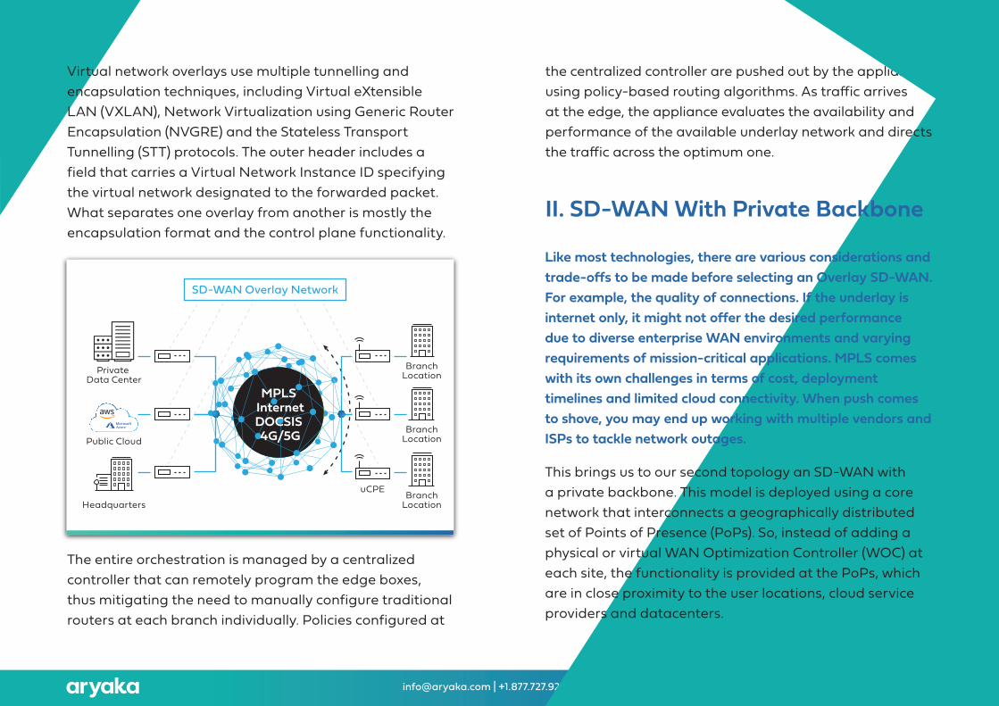
Virtual network overlays use multiple tunnelling and encapsulation techniques, including Virtual eXtensible LAN (VXLAN), Network Virtualization using Generic Router Encapsulation (NVGRE) and the Stateless Transport Tunnelling (STT) protocols. �e outer header includes afield that carries a Virtual Network Instance ID specifying the virtual network designated to the forwarded packet. What separates one overlay from another is mostly the encapsulation format and the control plane functionality.
the centralized controller are pushed out by the appliance using policy-based routing algorithms. As traffic arrives at the edge, the appliance evaluates the availability and performance of the available underlay network and directs the traffic across the optimum one.
�e entire orchestration is managed by a centralized controller that can remotely program the edge boxes, thus mitigating the need to manually configure traditional routers at each branch individually. Policies configured at
II. SD-WAN With Private Backbone
Like most technologies, there are various considerations and trade-offs to be made before selecting an Overlay SD-WAN. For example, the quality of connections. If the underlay is internet only, it might not offer the desired performance due to diverse enterprise WAN environments and varying requirements of mission-critical applications. MPLS comes with its own challenges in terms of cost, deployment timelines and limited cloud connectivity. When push comes to shove, you may end up working with multiple vendors and ISPs to tackle network outages.
�is brings us to our second topology an SD-WAN with a private backbone. �is model is deployed using a core network that interconnects a geographically distributed set of Points of Presence (PoPs). So, instead of adding a physical or virtual WAN Optimization Controller (WOC) at each site, the functionality is provided at the PoPs, which are in close proximity to the user locations, cloud service providers and datacenters.
Private Data Center
Public Cloud
uCPE
MPLS InternetDOCSIS 4G/5G
SD-WAN Overlay Network
Headquarters
BranchLocation
BranchLocation
BranchLocation
SD-WAN Architectures Explained (For external use) [email protected] | +1.877.727.9252
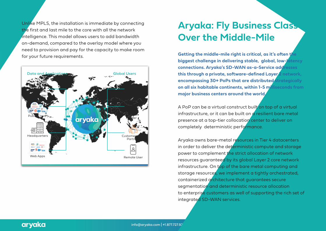
Unlike MPLS, the installation is immediate by connecting the first and last mile to the core with all the network intelligence. �is model allows users to add bandwidth on-demand, compared to the overlay model where you need to provision and pay for the capacity to make room for your future requirements.
Aryaka: Fly Business Class Over the Middle-MileGetting the middle-mile right is critical, as it’s o�en the biggest challenge in delivering stable, global, low-latency connections. Aryaka’s SD-WAN as-a-Service addresses this through a private, so�ware-defined Layer 2 network, encompassing 30+ PoPs that are distributed strategically on all six habitable continents, within 1-5 milliseconds from major business centers around the world.
A PoP can be a virtual construct built on top of a virtual infrastructure, or it can be built on a resilient bare metal presence at a top-tier collocation center to deliver on completely deterministic performance.
Aryaka owns bare-metal resources in Tier 4 datacenters in order to deliver the deterministic compute and storage power to complement the strict allocation of network resources guaranteed by its global Layer 2 core network infrastructure. On top of the bare metal computing and storage resources, we implement a tightly orchestrated, containerized architecture that guarantees secure segmentation and deterministic resource allocationto enterprise customers as well of supporting the rich set of integrated SD-WAN services.
Data Center
Headquarters
BranchUser
BranchUser
Customers and Partners
Remote User
Public Cloud
Web Apps
Global UsersData and Applications
SD-WAN Architectures Explained (For external use) [email protected] | +1.877.727.9252
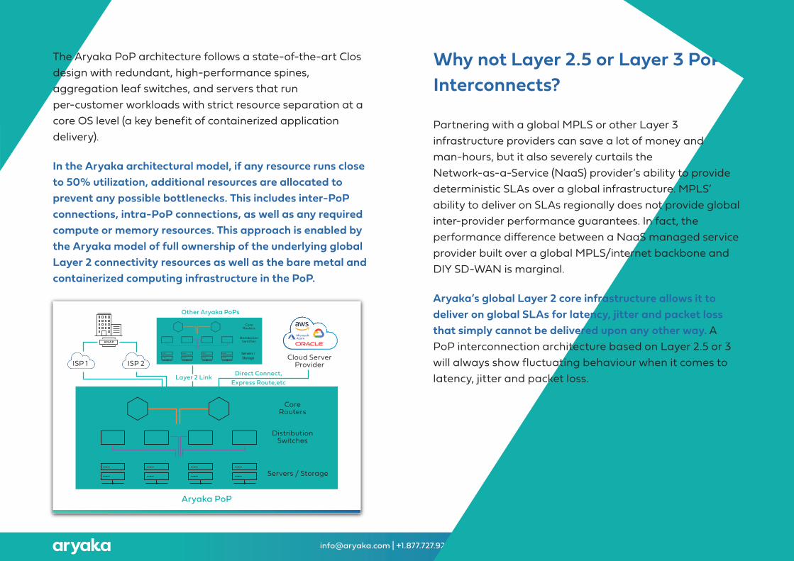
�e Aryaka PoP architecture follows a state-of-the-art Clos design with redundant, high-performance spines, aggregation leaf switches, and servers that run per-customer workloads with strict resource separation at a core OS level (a key benefit of containerized application delivery).
In the Aryaka architectural model, if any resource runs close to 50% utilization, additional resources are allocated to prevent any possible bottlenecks. �is includes inter-PoP connections, intra-PoP connections, as well as any required compute or memory resources. �is approach is enabled by the Aryaka model of full ownership of the underlying global Layer 2 connectivity resources as well as the bare metal and containerized computing infrastructure in the PoP.
Why not Layer 2.5 or Layer 3 PoP Interconnects?
Partnering with a global MPLS or other Layer 3 infrastructure providers can save a lot of money and man-hours, but it also severely curtails the Network-as-a-Service (NaaS) provider’s ability to provide deterministic SLAs over a global infrastructure. MPLS’ ability to deliver on SLAs regionally does not provide global inter-provider performance guarantees. In fact, the performance difference between a NaaS managed service provider built over a global MPLS/internet backbone and DIY SD-WAN is marginal.
Aryaka’s global Layer 2 core infrastructure allows it to deliver on global SLAs for latency, jitter and packet loss that simply cannot be delivered upon any other way. A PoP interconnection architecture based on Layer 2.5 or 3 will always show fluctuating behaviour when it comes to latency, jitter and packet loss.
Cloud ServerProvider
Aryaka PoP
Direct Connect,Express Route,etc
Layer 2 Link
Other Aryaka PoPs
Servers / Storage
DistributionSwitches
CoreRouters
ISP 1 ISP 2
A N A P
Servers /Storage

SD-WAN Architectures Explained (For external use) [email protected] | +1.877.727.9252
Layer 2 (MAC) vs. Layer 3 (IP) Networks
�ey say the devil is in the details. So, before we proceed, let’s quickly understand what makes Layer 2 special?
Most network engineers and architects focus their time and expertise on Layer 3, the Network Layer. It’s also the layer on which the internet operates. But, ask any networkengineer, and they will tell you that the best cloud access is experienced over Layer 2, not the internet.
As Layer 3 networks use IP addressing to determine the routing protocol and routing table, required to calculate the best path between the source and destination, there is a certain buffer time required at the routers for examining the data packets. An event that adds to the latency.
Layer 2, on the other hand, uses MAC addressing, and relies on packet switching instead of routing. �e benefit? Low and stable latency. L2 sends the data on a dedicated point-to-point connection and does so at lightning speed.
�e key to guaranteeing application performance is how your service provider decides to orchestrate the core for optimizing the traffic. You’ve already won half the battle if they get the L2 foundation correct, as this results in stable
latency and limited packet loss. Plus, users can tune TCP to limit packet acknowledgments, resulting in substantial throughput gains.
�e bottom line: You can choose to have your SD-WAN delivered over the internet and MPLS, or you can have it delivered over a Layer 2 private backbone that guaranteesconsistent application performance globally.
Are the Functions Handling Transport, Encryption and Protocol Acceleration Merely Virtualized Functions Running on a VM?
While NFV is a powerful technology that can bundle up multiple functions in a single device at the network edge, there are performance issues when it’s used in a virtualized PoP in the core network delivering on large scale services. �e Aryaka PoP leverages very granular, per-customer containerization technology running on bare metal servers to deliver always-on, deterministic performance. Containers, being far more lightweight than hypervisors, deliver superior performance and scalability, which is of great relevance when supporting service chaining at scale.
SD-WAN Architectures Explained (For external use) [email protected] | +1.877.727.9252
�is strict separation also serves security purposes, since the traffic from every branch is handled by a singular container workload that handles transport and encryption functions (TurboNet). A separate dedicated container instance handles protocol acceleration duties (TurboApp).
A Service Node
�e appropriate classification for an Aryaka PoP would be a “service node,” or “service PoP,” that is, an architecture that provides a host of advanced services such as first/last mileoptimization, protocol acceleration, application optimization and optimal peering to cloud services. �e global PoPs can also easily be peered with IaaS, PaaS, SaaS and UCaaSproviders and help to deliver an optimal cloud-friendly network topology.

SD-WAN Architectures Explained (For external use) [email protected] | +1.877.727.9252
Let’s compare the Aryaka architecture with alternative architectures, which exercise little to no control over the global middle-mile, the last-mile, or the virtualized infrastructure underlying the SD-WAN deployment.
Litmus Test
SD-WAN Architectures Explained (For external use) [email protected] | +1.877.727.9252
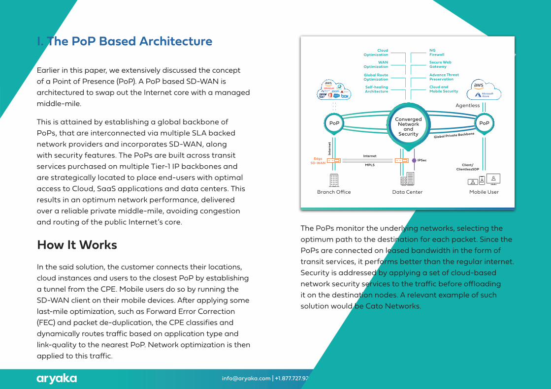
I. �e PoP Based Architecture
Earlier in this paper, we extensively discussed the concept of a Point of Presence (PoP). A PoP based SD-WAN is architectured to swap out the Internet core with a managed middle-mile.
�is is attained by establishing a global backbone of PoPs, that are interconnected via multiple SLA backed network providers and incorporates SD-WAN, along with security features. �e PoPs are built across transit services purchased on multiple Tier-1 IP backbones and are strategically located to place end-users with optimal access to Cloud, SaaS applications and data centers. �is results in an optimum network performance, delivered over a reliable private middle-mile, avoiding congestion and routing of the public Internet’s core.
�e PoPs monitor the underlying networks, selecting the optimum path to the destination for each packet. Since the PoPs are connected on leased bandwidth in the form of transit services, it performs better than the regular internet. Security is addressed by applying a set of cloud-based network security services to the traffic before offloading it on the destination nodes. A relevant example of such solution would be Cato Networks.
How It WorksIn the said solution, the customer connects their locations, cloud instances and users to the closest PoP by establishing a tunnel from the CPE. Mobile users do so by running the SD-WAN client on their mobile devices. A�er applying some last-mile optimization, such as Forward Error Correction (FEC) and packet de-duplication, the CPE classifies and dynamically routes traffic based on application type and link-quality to the nearest PoP. Network optimization is then applied to this traffic.
PoPPoP
Data Center
IPSecInternet
Self-healingArchitecture
Global RouteOptimization
WANOptimization
CloudOptimization
Cloud and Mobile Security
Advance �reatPreservation
Secure Web Gateway
NG Firewall
Inte
rnet
MPLS Client/ClientlessSDP
ConvergedNetwork
andSecurity
Global Private Backbone
EdgeSD-WAN
Agentless
Branch Office Mobile User
SD-WAN Architectures Explained (For external use) [email protected] | +1.877.727.9252
�e PoP based architecture does an exceptional job at amplifying the middle-mile performance, but only if you do it right. Most vendors run their core-network on Layer 3 internet links, with minimal to no redundancy. �is leaves the application performance suspectable to high variance of jitter due to peering between service providers.
Aryaka’s solution tames the middle-mile by offering L2 private links that leveragesbest-of-breed tier 1 providers with redundancy built-in on the edge of the PoP as wellas on the core, using full-mesh circuits. �e SLAs begin from day one and can be validated by the customer using the MyAryaka cloud portal.
Secondly, since the impact of middle-mile is quite significant on the overall network performance, optimization becomes pivotal. While most vendors provide limited optimization, Aryaka supports compression, de-duplication, WAN rate control,SSL optimization, SMB signing, FEC and Advanced Redundancy Removal, all patentedfeatures.
If you’re going all out to build the network of your dreams, you might as well do it right. �ough this model checks a lot of right boxes, most vendors get the foundational element wrong.
Observations
SD-WAN Architectures Explained (For external use) [email protected] | +1.877.727.9252
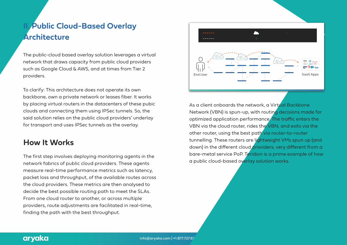
II. Public Cloud-Based OverlayArchitecture
�e public-cloud based overlay solution leverages a virtual network that draws capacity from public cloud providers such as Google Cloud & AWS, and at times from Tier 2 providers.
To clarify: �is architecture does not operate its own backbone, own a private network or leases fiber. It works by placing virtual routers in the datacenters of these pubic clouds and connecting them using IPSec tunnels. So, the said solution relies on the public cloud providers’ underlay for transport and uses IPSec tunnels as the overlay.
As a client onboards the network, a Virtual Backbone Network (VBN) is spun-up, with routing decisions made for optimized application performance. �e traffic enters the VBN via the cloud router, rides the VBN, and exits via the other router, using the best path via router-to-router tunnelling. �ese routers are lightweight VMs spun up (and down) in the different cloud providers, very different from a bare-metal service PoP. Teridion is a prime example of how a public cloud-based overlay solution works.
How It Works�e first step involves deploying monitoring agents in the network fabrics of public cloud providers. �ese agents measure real-time performance metrics such as latency, packet loss and throughput, of the available routes across the cloud providers. �ese metrics are then analysed to decide the best possible routing path to meet the SLAs. From one cloud router to another, or across multiple providers, route adjustments are facilitated in real-time, finding the path with the best throughput.
End User SaaS Apps
Congested Internet Backbone
Virtual Network Public Cloud Monitoring Agents
Cloud Router

SD-WAN Architectures Explained (For external use) [email protected] | +1.877.727.9252
�is solution can be best thought of as a GPS that steers the internet traffic to a path ofminimum latency, packet loss and jitter. While it is worthy of being a complimentary service, it is no replacement for an end-to-end SD-WAN solution.
Coming to the optimization part of it, this solution does not provide benefits such as TCP optimization, compression or de-duplication as a default feature. Getting these features call for an additional investment in a separate SD-WAN provider. A hybrid set-up may include 3rd party SD-WAN boxes at the edge and the router based routing in the middle-mile — meaning two different vendors.
Picture a scenario where you’re sending a file from Australia to the US. At best, this architecture can reduce the number of hops, get the best available path over the internet and maybe marginally increase the throughput in the process. But the middle-mile will still gobble up a good chunk of the application performance. Aryaka, in contrast, directly connects users to the applications in a full mesh set-up, whether the applications are hosted on-premise, in the cloud, in a hybrid set-up or anything in between!
�e said solution is a viable option if budget takes priority over performance. It might be a good way to remove the term commitment or high cost of MPLS, or extract a little more out of the internet connection; which makes us wonder how ineffective traditional internet routing is in the first place.
Observations
SD-WAN Architectures Explained (For external use) [email protected] | +1.877.727.9252
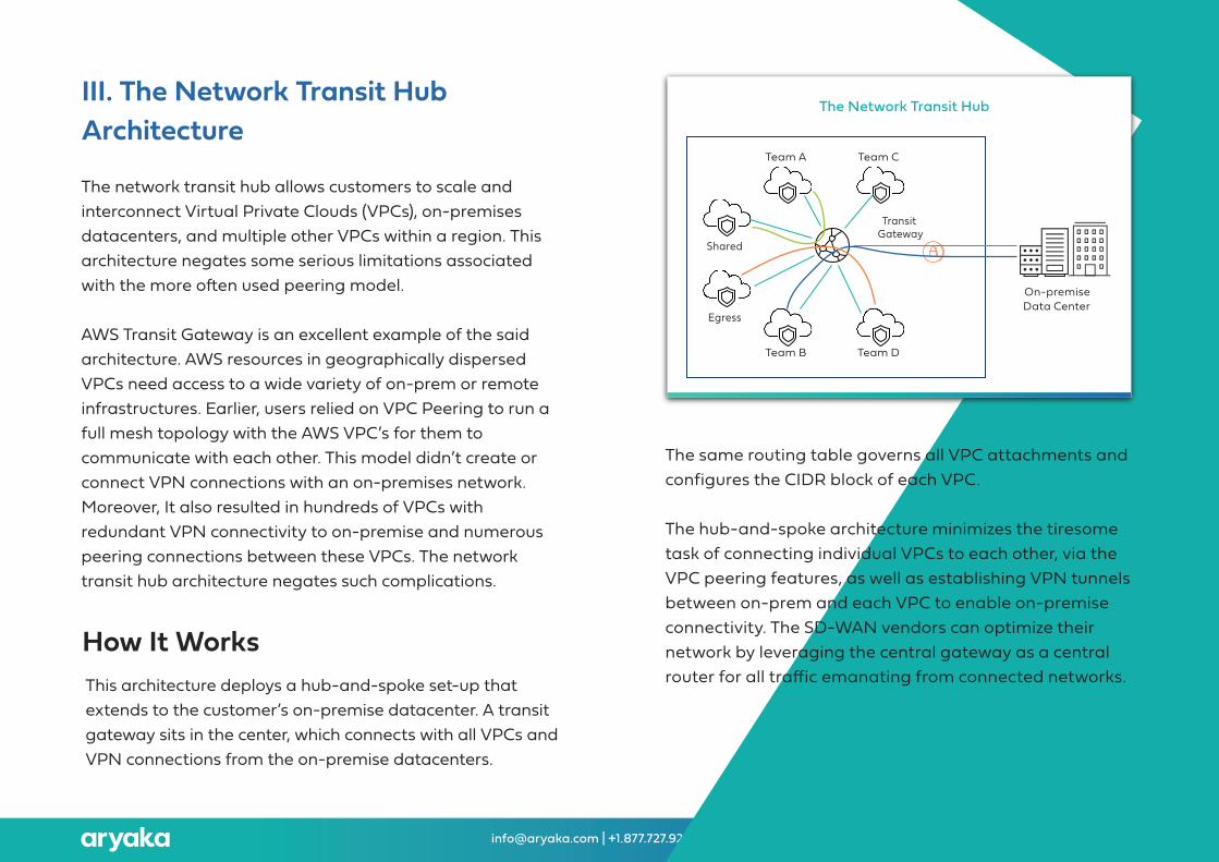
III. �e Network Transit HubArchitecture
�e network transit hub allows customers to scale and interconnect Virtual Private Clouds (VPCs), on-premises datacenters, and multiple other VPCs within a region. �is architecture negates some serious limitations associated with the more o�en used peering model.
AWS Transit Gateway is an excellent example of the said architecture. AWS resources in geographically dispersed VPCs need access to a wide variety of on-prem or remote infrastructures. Earlier, users relied on VPC Peering to run a full mesh topology with the AWS VPC’s for them to communicate with each other. �is model didn’t create or connect VPN connections with an on-premises network. Moreover, It also resulted in hundreds of VPCs with redundant VPN connectivity to on-premise and numerous peering connections between these VPCs. �e network transit hub architecture negates such complications.
How It Works
�e same routing table governs all VPC attachments and configures the CIDR block of each VPC.
�e hub-and-spoke architecture minimizes the tiresome task of connecting individual VPCs to each other, via the VPC peering features, as well as establishing VPN tunnels between on-prem and each VPC to enable on-premise connectivity. �e SD-WAN vendors can optimize their network by leveraging the central gateway as a central router for all traffic emanating from connected networks.�is architecture deploys a hub-and-spoke set-up that
extends to the customer’s on-premise datacenter. A transit gateway sits in the center, which connects with all VPCs and VPN connections from the on-premise datacenters.
On-premiseData Center
Team A
Shared
Transit Gateway
Egress
Team B
Team C
Team D
�e Network Transit Hub
SD-WAN Architectures Explained (For external use) [email protected] | +1.877.727.9252
�e network transit hub architecture can help SD-WAN vendors in a significant way. Consider the AWS example, for instance, where the SD-WAN vendors can cut down on the number of leased lines required to operate their network and instead leverage the AWS backbone.
�e inter-region traffic can ride the Amazon global network via the transit gateway’s inter-region peering for improved application performance at a lower cost. Where required, Aryaka will implement AWS Transit Gateway interworking, in the same way we’ve integrated with the Azure VWAN.
Observations
SD-WAN Architectures Explained (For external use) [email protected] | +1.877.727.9252
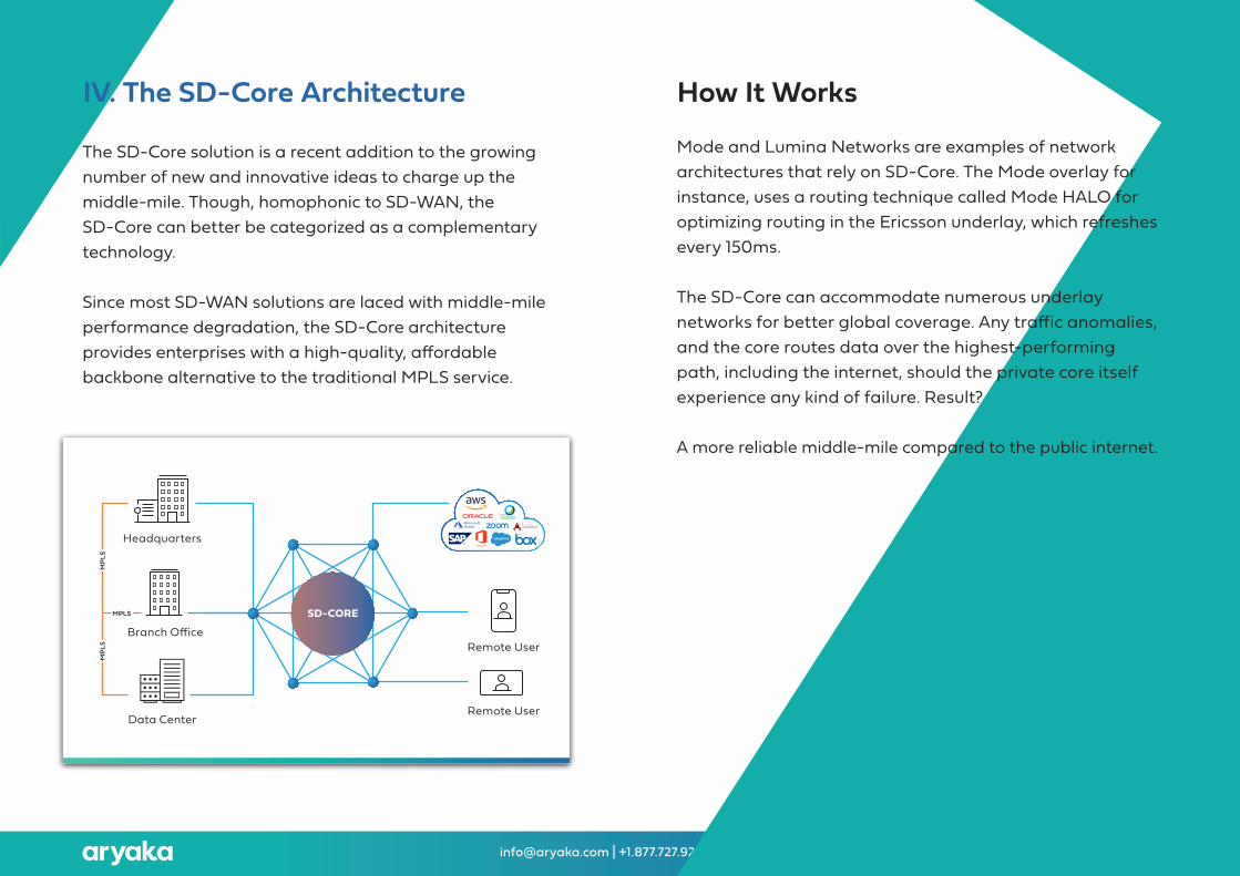
IV. �e SD-Core Architecture
�e SD-Core solution is a recent addition to the growing number of new and innovative ideas to charge up the middle-mile. �ough, homophonic to SD-WAN, the SD-Core can better be categorized as a complementary technology.
Since most SD-WAN solutions are laced with middle-mile performance degradation, the SD-Core architecture provides enterprises with a high-quality, affordable backbone alternative to the traditional MPLS service.
How It Works
Mode and Lumina Networks are examples of network architectures that rely on SD-Core. �e Mode overlay for instance, uses a routing technique called Mode HALO for optimizing routing in the Ericsson underlay, which refreshes every 150ms.
�e SD-Core can accommodate numerous underlay networks for better global coverage. Any traffic anomalies, and the core routes data over the highest-performing path, including the internet, should the private core itself experience any kind of failure. Result?
A more reliable middle-mile compared to the public internet.
Remote User
Remote User
Headquarters
Data Center
Branch Office
MP
LS
MPLS
MP
LS
SD-CORE

SD-WAN Architectures Explained (For external use) [email protected] | +1.877.727.9252
SD-Core might work well for a few use cases, but an end-to-end SD-WAN solution addresses much more and includes optimization — among many other benefits. SD-Core alone fails to provide network optimization techniques such as compression,TCP and UDP Optimization, data de-duplication, SSL & CIFS acceleration, loadbalancing, path selection, packet loss recovery and error correction.
Secondly, the idea behind SD-Core was to bring MPLS grade private connectivity at an affordable rate, but it still requires an SD-WAN vendor at each edge for reaping full benefits. �is means enterprises with dispersed global remote locations and diversified SD-WAN vendors must brace for a multi-vendor management nightmare. In contrast, Aryaka offers a “one hand to shake” model for end-to-end network management.
Moreover, SD-Core architecture has no provisions for direct connectivity to IaaS and SaaS vendors. Aryaka, on the other hand, addresses multi-cloud connectivity using private connections (e.g., AWS Direct Connect, Azure ExpressRoute), enabling enterprises to leverage Aryaka’s private core network with built-in WAN optimization features.
On a closing note, no matter what you call it — leased line, dedicated fiber, privatenetwork, private backbone, etc. — if it is L3, it is no better than the internet and theperformance will reflect that.
Observations
SD-WAN Architectures Explained (For external use) [email protected] | +1.877.727.9252
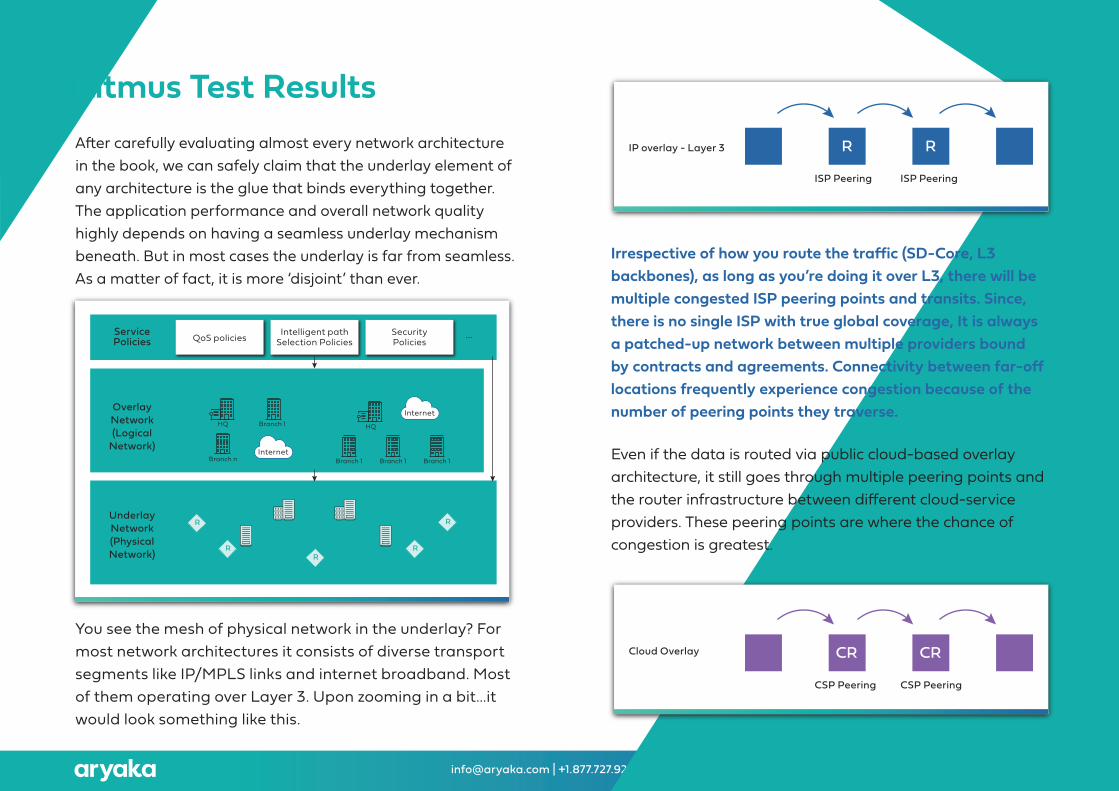
Litmus Test ResultsA�er carefully evaluating almost every network architecture in the book, we can safely claim that the underlay element of any architecture is the glue that binds everything together. �e application performance and overall network quality highly depends on having a seamless underlay mechanism beneath. But in most cases the underlay is far from seamless. As a matter of fact, it is more ‘disjoint’ than ever.
You see the mesh of physical network in the underlay? For most network architectures it consists of diverse transport segments like IP/MPLS links and internet broadband. Most of them operating over Layer 3. Upon zooming in a bit...it would look something like this.
Irrespective of how you route the traffic (SD-Core, L3 backbones), as long as you’re doing it over L3, there will be multiple congested ISP peering points and transits. Since, there is no single ISP with true global coverage, It is always a patched-up network between multiple providers bound by contracts and agreements. Connectivity between far-off locations frequently experience congestion because of the number of peering points they traverse.
Even if the data is routed via public cloud-based overlay architecture, it still goes through multiple peering points and the router infrastructure between different cloud-service providers. �ese peering points are where the chance of congestion is greatest.
ServicePolicies
OverlayNetwork(Logical
Network)
UnderlayNetwork(PhysicalNetwork)
QoS policies Intelligent pathSelection Policies
SecurityPolicies
...
Logical Network 1 Logical Network 1
HQ
Branch n
Branch 1
Internet
Internet
Branch 1
HQ
Branch 1 Branch 1
R
RR
R
R
Cloud Overlay
CSP Peering CSP Peering
CR CR
IP overlay - Layer 3
ISP Peering ISP Peering
R R
SD-WAN Architectures Explained (For external use) [email protected] | +1.877.727.9252
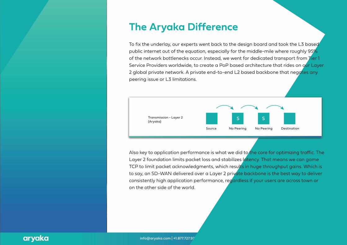
To fix the underlay, our experts went back to the design board and took the L3 based public internet out of the equation, especially for the middle-mile where roughly 95% of the network bottlenecks occur. Instead, we went for dedicated transport from Tier 1 Service Providers worldwide, to create a PoP based architecture that rides on our Layer 2 global private network. A private end-to-end L2 based backbone that negates any peering issue or L3 limitations.
Also key to application performance is what we did to the core for optimizing traffic. �e Layer 2 foundation limits packet loss and stabilizes latency. �at means we can game TCP to limit packet acknowledgments, which results in huge throughput gains. Which is to say, an SD-WAN delivered over a Layer 2 private backbone is the best way to deliver consistently high application performance, regardless if your users are across town or on the other side of the world.
�e Aryaka Difference
Transmission - Layer 2(Aryaka)
No Peering No Peering DestinationSource
S S
SD-WAN Architectures Explained (For external use) [email protected] | +1.877.727.9252
Media-rich applications, network-aware devices, hardware virtualization and every other soaring trend on the list, require your WAN service delivery to transition from being dumb transport pipes into an intelligent piece of fiber that can tie down the cloud, datacenter, hub, branch, remote sites and every other infrastructural element that power IT.
�at brings us to re-engineering the network architecture — an essential piece of the network management equation. If businesses keep counting on the same old ingredients and recipes to cook new dishes, it is not going to work. MPLS and Internet did a great job getting you this far, but that's it.
Considering how complex, sprawling, multi-tiered, bandwidth-hungry and opaque today’s applications are, the networks of yesterday can barely meet the requirements of the present, much less the future. Enterprises need to innovate before it’s too late.
�e challenge is that today’s CIOs are expected to be agents of change, but it’s o�en difficult to convince the rest of the C-suite to embrace IT disruption. When enterprises do take that leap of faith into lesser-known territories, they at least want to be able to sleep easy at night knowing their vendors will be partners with willingness to go the extra mileto ensure their success.
Aryaka has been in the SD-WAN space for almost a decade with a proven technology that continues to evolve and innovate to meet the market’s needs. �ere is no one-size-fits-all approach because Aryaka’s managed services are tailored to each customer, bringing operational simplicity to dynamic, complex environments.
For further reading about our PoP architecture, check out our whitepaper, here.To get a free demo and experience the Aryaka difference, , Click here.
Conclusions
LEARN MORE | [email protected] | +1.877.727.9252
*Disclaimer- �is report is an interpretation of publicly available information that are considered reliable. �is report does not claim to validate the veracity of the information contained within. Please refer to the ‘references’ section of the report for a comprehensive list of sources referred to, while collating this report.”
David Ginsburg- VP of Product and Solutions Marketing
Editor
Nishant Singh- Senior Product Marketing Specialist
Author
About Aryaka NetworksAryaka, the Cloud-First WAN company, brings agility, simplicity and a great experience to consuming the WAN-as-a-service. An optimized global network and innovative technology stack delivers the industry’s #1 managed SD-WAN service and sets the gold standard for application performance. Aryaka’s SmartServices offers connectivity, application acceleration, security, cloud networking and insights leveraging global orchestration and provisioning. �e company’s customers include hundreds of global enterprises including several in the Fortune 100.