Embed Size (px)
Citation preview
4.1.1 Compliance 014.1.2 InitialAssessment–deskstudy
(allsites) 034.1.3 InitialAssessment–walkoversurvey
(allsites) 044.1.4 InitialAssessment–results 044.1.5 BasicInvestigation
(siteswherehazardsarenotidentifiedorsuspected) 05
4.1.6 DetailedInvestigation(siteswherehazardsareidentifiedorsuspected) 05
4.1.7 Managingtherisks(siteswherehazardsarefound) 06
4.1.8 Unforeseenhazards 074.1.9 Documentationandverification 074.1.10 Guidanceforinvestigations 074.1.11 Furtherinformation 08
This chapter gives guidance on meeting the Technical Requirements for assessing and managing land quality.
Land quality – managing ground conditions
CHAPTER 4.1
4.1
1 Land quality – managing ground conditions 2020
CHAPTER 4.1 1
Introduction
This chapter provides a framework for managing geotechnical and contamination risks, with the objective of ensuring that:
�� all sites are properly assessed and investigated for potential geotechnical and contamination hazards�� foundations and substructure designs are suitable for the ground conditions
�� sites are properly remediated where necessary or appropriate, and design precautions are taken�� appropriate documentation and verification is provided to NHBC.
4.1.1 Compliance Also see: Chapter 4.2
Assessment of the site and the surrounding area shall comply with the Technical Requirements. Items to be taken into account include:a) suitability of persons for the level of investigationb) geotechnical and contamination issuesc) investigation procedures
d) notification in writing to NHBC of hazardous ground conditions.
Ground investigations and management of risk that complies with the guidance in this chapter will generally be acceptable.
Suitable persons for the level of investigationThe following skills and knowledge are required from the person responsible for the Initial Assessment, Basic Investigation and documentation and verification. They should:
�� understand the hazards that can affect the development and where they originate�� recognise the signs of potential hazards �� conduct a desk study and walkover survey
�� collect information relating to such hazards on and adjacent to the site �� report the findings in a clear and concise manner�� determine when specialist advice and detailed testing is required.
The following criteria should be used as guidance for the appointment of a consultant or specialist responsible for Detailed Investigation, management of hazards, documentation and verification:
Experience Similar types of site and development.Appropriate discipline(s) Understanding of all relevant skills required on the project and access to other disciplines,
including geologists, hydrogeologists, toxicologists and environmental chemists.Legislation Understanding of legislation and liabilities associated with the site.Professional indemnity insurance Appropriate cover for the work being carried out.Health and safety Awareness of occupational hygiene issues and Health and Safety legislation.Quality assurance Use of a quality management system, including appropriately accredited laboratories.Project management Ability to manage a project team consisting of the appropriate disciplines.Site investigation Ability to design site investigation programmes, including soil sampling, testing and
laboratory analysis.Risk management Ability to conduct risk assessments as required by the risk management process.Reporting and communication Ability to prepare comprehensive and well presented reports. Effective communication
within their organisation and with the client, statutory authorities and the general public.Engineering design Understanding of effective risk reduction techniques, e.g. engineered foundations and
substructure details of suitable remediation.
Geotechnical and contamination issuesAssessment should be carried out by direct investigation and examination of the ground, supplemented by laboratory testing where necessary, in order to determine the geotechnical and contamination characteristics of the site.
Specifically, where contamination is suspected or found, the site should be assessed using the Source-Pathway-Receptor framework (known as the pollutant linkage).
For land contamination to occur, a source, pathway and receptor must all exist. A written or diagrammatic representation of the land contamination (known as a Conceptual Model), should be produced to show the possible relationships between each.
4.1
Land quality – managing ground conditions 2020
CHAPTER 4.1 22
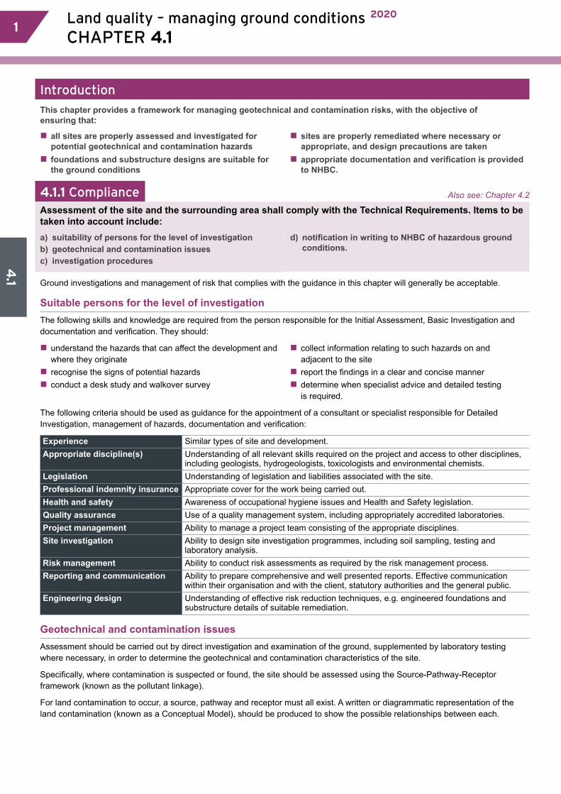
ProcedureThe process to assess and manage the ground conditions is as follows:
Initial AssessmentNHBC requires all sites to be assessed by a desk study and a walkover survey. The results should be used to determine whether or not hazards are known or suspected.
Basic InvestigationRequired to support the results of the Initial Assessment where hazards are not suspected.
Detailed InvestigationRequired where hazards are known or suspected.
Further Assessment Required after the Basic or Detailed Investigation has been conducted, to confirm that all objectives have been met. Where results are inconclusive, further investigation will be required.
HazardsWhere hazards are identified, design precautions or remediation will be required to minimise their effects.
If any unforeseen hazards are found during the course of construction, further investigation may be required.
Documentation and verificationNHBC requires documentation and verification to show that:
�� the site has been properly assessed and investigated �� where necessary, suitable precautions are incorporated into the design �� all necessary remediation has been carried out.
Initial Assessment:■ desk study■ walkover study■ results.
Yes No
Yes
Finish construction phase
No Yes
No
YesNo
Hazards known or suspected?
Basic Investigation
Further Investigationrequired?
Manage risks
Provide documentationand verification
Start construction phase
Unforeseen hazards
Detailed Investigation
Further Assessment:geotechnical and contamination risks acceptable?
Notification of potential hazards and associated risksIf a site (defined in the Rules as an area of land that is covered by a single detailed planning consent or series of consents relating to continuous development) is classed as ‘hazardous’, NHBC must be notified in writing a minimum of eight weeks before work starts. Failure to provide such information may delay the registration process, the construction work and the issuing of NHBC warranty.

4.1
3 Land quality – managing ground conditions 2020
CHAPTER 4.1 3
Table 1: Potential hazards and associated risks
Potential hazard Associated riskHigh water table or low-lying land �� flooding
�� the effects from toxic or noxious materials which could be concentrated or transported by ground water.
Mining (past, present and proposed) �� ground movement as a result of the type of mining and materials extracted�� ground gasses, including methane and carbon dioxide.
Trees �� shrinkage and heave of clay soils �� physical damage caused by roots.
Peat �� acid attack�� changes in volume due to variations in moisture content�� production of methane and carbon dioxide.
Infill and made ground, including tipping �� release of gases which may be explosive or asphyxiating�� low bearing capacity causing excessive total and/or differential settlements�� consolidation characteristics which may result in subsidence, settlement and/or excessive tilt�� localised ground variability (laterally and with depth) which may result in subsidence, settlement and/or excessive tilt�� collapse compression or inundation settlement of non-cohesive fills which may result in subsidence, settlement and/or excessive tilt.
Low bearing capacity ground �� settlement of foundations and substructures.Former buildings or structures �� underground obstructions producing variations in bearing capacity and
settlement characteristics.Adjacent buildings �� effect on stability of both new and existing buildings.Drains, including land drains �� contamination, flooding, waterlogging and interruption of land drainage systems.Sulfates in ground or ground water �� expansive reaction
�� chemical attack on concrete, mortar and bricks or blocks made with cement.Contamination �� from substances which may be carcinogenic, toxic, asphyxiating, corrosive,
phytotoxic, combustive, explosive or radioactive.Solution features in chalk and limestone, including swallow holes
�� underground cavities.
Unstable ground subject to landslip �� ground movement.Seas, lakes and rivers adjacent to land �� erosion.
4.1.2 Initial Assessment – desk study (allsites)
A desk study of the site and the surrounding area, that covers key and existing site information, shall be undertaken by a suitable person and include investigation of soils, geology, surface water, ground water, current and historical uses.
A desk study is the collection and examination of existing information obtained from a wide variety of sources. It should indicate potential hazards at an early stage and provide a basis for the investigation. Potential problems should be assessed according to the current and historical uses of the site and surrounding area, including those which may have been left by:
�� industrial, commercial and agricultural uses, including storage �� mining
�� quarrying �� landfilling and tipping.
Key information sources include:
�� the Environment Agency or its equivalent – for example, coastal erosion, landfill sites, details of water abstraction�� the local authority – for example planning and environmental health �� British Geological Survey, maps and information �� Ordnance Survey, current and previous editions of plans and aerial photographs�� Coal Authority, mining reports – past, present and proposed mining
�� utility companies �� county records offices, libraries, museums and local history sources �� soil survey maps �� the site vendor�� in-house information �� ongoing monitoring.
4.1
Land quality – managing ground conditions 2020
CHAPTER 4.1 44
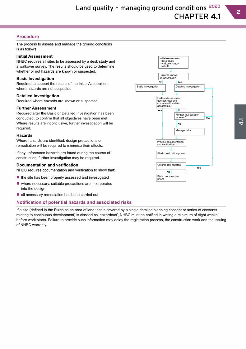
4.1.3 Initial Assessment – walkover survey (allsites)
To assess ground conditions, a walkover survey of the site and the surrounding area shall be undertaken by a suitable person.
A walkover survey is a direct inspection of the site and the surrounding area carried out in conjunction with the desk study. Indications of any potential hazards should provide a basis for the investigation. A photographic record of the site can help in the reporting of the walkover survey.
Table 2: Potential hazards
Source of information Items to be taken into accountTopography �� abrupt changes in slope
�� valley bottoms or depressions which may be soft or filled�� evidence of overburden on slopes�� excavations at the base of the slope�� signs of landslip, e.g. tilting trees, posts or walls�� signs of subsidence�� evidence of imported soil including local surface depressions, tipped material or rubbish, particularly if it is hot or has an odour.
Soils and rocks �� the basic ground type�� evidence of peat, silt or other highly compressible material at or below the surface�� cracking or stickiness of the surface which may indicate a shrinkable sub-soil�� sudden changes in conditions, e.g. clay to chalk or soil to rock.
Surface water and vegetation
�� a high water table indicated, e.g. by waterlogged ground�� signs of flooding�� reeds or water-loving plants�� springs, ponds, wells, ditches or streams�� the source of any discoloured water.
Vegetation �� vegetation which may indicate the nature of the soils�� sparse dead or dying vegetation�� type and condition of vegetation on land adjoining the site�� species, height and condition of the trees�� species, height, spread and condition of hedges and scrub on clay�� evidence of former trees, hedges or scrub on clay.
Structural information �� damage to structures, e.g. cracking in buildings, on or around the site�� other evidence of movement, e.g. tilting or distortion�� any structures or services below ground.
Local information �� local knowledge of the site, e.g. mining, refuse tipping or flooding�� local industrial history records indicating past and present uses of the site�� place names and street names that may give clues to previous site usage, e.g. Brickfield Cottage, Water Lane.
4.1.4 Initial Assessment – resultsThe results of the desk study and walkover survey shall be recorded and evaluated by a suitable person.
Initial results should be evaluated for suspected hazards and the results recorded, and include the following as appropriate:
�� site plans, including dates, previous and current uses, and proposed site layout�� geology of the site, including geological maps, previous site investigations and laboratory test results
�� photographs, including aerial photographs, showing points of interest or concern (e.g. areas of ground instability), interpretation of aerial photographs, and dates of photographs�� list of sources of information consulted and copies of the information obtained.
4.1
5 Land quality – managing ground conditions 2020
CHAPTER 4.1 5
4.1.5 Basic Investigation (siteswherehazardsarenotidentifiedorsuspected)Also see:
BS EN 1997-2
Where hazards are not suspected, a Basic Investigation of the site, including geotechnical and contamination investigations, shall be carried out by a suitable person and recorded to the satisfaction of NHBC.
The Basic Investigation aims to provide assurance for all sites, regardless of how free of hazards they may appear, and forms the minimum requirement for a site investigation.
The number and depth of trial pits should be located so they are representative of the site and will depend upon the:
�� proposed development �� nature of the site
�� inconsistency of the soil and geology across the site.
Trial pits should be located outside the proposed foundation area, and generally be a minimum of 3m deep. The distance from the edge of the foundation should not be less than the depth of the trial pit. Where trial pits do not provide sufficient information, boreholes will be necessary.
Basic geotechnical and contamination investigations should be conducted and include:
�� physical tests, such as plasticity index tests, to support the results of the Initial Assessment
�� a basic contamination investigation based on sampling and testing of soil taken from trial pits during the geotechnical investigation.
During the excavation of the trial pits, the use of sight and smell may help to identify certain contaminants.
If the Basic Investigation reveals the presence of geotechnical and/or contamination hazards, or has not addressed all of the original objectives, or where there is any doubt about the condition of the ground, further Detailed Investigation should be conducted.
4.1.6 Detailed Investigation (siteswherehazardsareidentifiedorsuspected)
Where hazards are identified or suspected, a Detailed Investigation of the site shall be conducted under the supervision of a consultant or specialist acceptable to NHBC to determine and report on the nature and extent of the conditions.
A Detailed Investigation should be carried out where hazards are identified or suspected:
�� from the outset �� from the initial results of the desktop study and walkover survey, or
�� from the Basic Investigation.
A consultant or specialist acceptable to NHBC should be appointed to:
�� design and supervise the Detailed Investigation �� present all the factual data obtained from the Detailed Investigation.
In addition to the Basic Investigation, the Detailed Investigation should adopt a clearly defined, structured approach, gathering information which considers the:
�� immediate site and the adjacent area �� possibility of future development in the vicinity of the site �� nature of the development �� complexity of the ground conditions �� extent of influence of the proposed foundations
�� presence of soil gas (if there is any possibility a full gas investigation should be carried out and include flow measurements) �� surface water and ground water conditions, soils and geology, and site history.
The problems and liabilities which have to be managed in order to develop the site should be clearly communicated in the Detailed Investigation report.
Further investigation should be conducted if the Detailed Investigation has not satisfactorily addressed all of the original objectives.

4.1
Land quality – managing ground conditions 2020
CHAPTER 4.1 66
4.1.7 Managing the risks (siteswherehazardsarefound)
Hazardous ground conditions shall be satisfactorily managed under the supervision of a consultant or specialist acceptable to NHBC. Items to be taken into account include:a) design precautionsb) remediation techniques
c) a method statement and report.
The consultant or specialist should:
�� identify any results which show that design precautions and/or remediation may be necessary �� conduct a risk assessment to determine appropriate design precautions and/or remedial treatment �� specify the options for remediating any contamination that may be present and provide a remediation method
statement �� make recommendations for appropriate design precautions as necessary, including all underground services on the site and any ground improvement techniques�� ensure the works are appropriately supervised �� produce a remediation report.
The proposed solutions for dealing with geotechnical and/or contamination hazards should make due allowance for any constraints that apply, for example:
�� factors associated with the site and surrounding area which could restrict the design precautions or remediation techniques should be identified�� local and statutory requirements should be met to avoid abortive works
�� time constraints may influence the choice of solution, but do not alter the requirement for effective remediation.
Design precautionsSolutions for dealing with geotechnical hazards include:
�� specialist foundations such as rafts, piling and ground beams
�� ground improvement techniques such as vibro, dynamic compaction and surcharging.
Remediation techniquesSolutions for dealing with contamination hazards include:
�� risk avoidance by changing the pathway or isolating the target, by adjusting the layout and/or by building protective measures into the construction�� engineering-based treatments that remove or isolate contaminants or modify the pathway by excavation, providing ground barriers or covering and capping
�� process-based treatment to remove, modify, stabilise or destroy contaminants by physical, biological, chemical or thermal means.
Remediation method statement and reportThe remediation method statement should detail the strategy for the site and include the:
�� original risk assessment, identification of the remediation objectives and outline information for the method chosen �� remediation objectives for ground, ground water and soil gas
�� working method for implementing remediation �� waste classification and methods for control and disposal �� proposed supervision and monitoring of remediation �� validation sampling and testing to be implemented.
The report should include the following information:
�� photographic records, especially for work which will be buried (e.g. membranes) �� site diaries or drawings, environmental supervisor’s site diary and independent witness statements where appropriate �� accurate surveys of the levels and position of all remediated areas �� a description of any remedial materials used
�� details of soil movements and waste transfer notes �� results of post-remediation sampling (laboratory certificates should be provided in appendices) �� validation test results �� results of monitoring �� details of all consultations and meetings with statutory authorities.

4.1
7 Land quality – managing ground conditions 2020
CHAPTER 4.1 7
4.1.8 Unforeseen hazardsWhere additional or unforeseen hazards arise during construction, the builder shall ensure investigation and management satisfactory to NHBC.
Where additional or unforeseen hazards arise, specialist advice is required so that the hazard is properly investigated, managed and verified.
4.1.9 Documentation and verificationDocumentation and verification shall be provided to the satisfaction of NHBC to demonstrate that the site is suitable for the proposed development. All relevant information, designs, specifications and reports shall be produced in a clearly understandable format and distributed to appropriate personnel.
Where the site is within an area susceptible to radon, it will be necessary to follow appropriate guidance in the building regulations and associated documents. The information detailed in Table 3 should be provided to NHBC.
Table 3: Information required by NHBC
Geotechnical hazards present: Yes No Yes NoContamination hazards present: Yes Yes No NoInitial Assessment, Further Assessment and Basic Investigation ■ ■ ■ ■Detailed Investigation ■ ■ ■Proposals to manage geotechnical risks ■ ■Proposals to manage contamination risks ■ ■Verification evidence ■ ■ ■ ■
Note: Evidence may still be required by NHBC to substantiate that contamination and hazards are not present on the site.
4.1.10 Guidance for investigations Site investigations shall be undertaken in accordance with BS EN 1997-2 and recognised practice. Items to be taken into account include: a) investigation techniqueb) sampling
c) testing.
Investigation techniqueA site investigation normally comprises techniques which are classed as either indirect or direct.
Indirect investigations use geophysical techniques, including electromagnetic, resistivity, seismic, gravity and ground radar, to interpret ground conditions. Conducted from the surface, they measure variations in properties of the ground, both horizontally and vertically, to define subsurface conditions. Geophysical methods rely on contrasts in the physical properties, for example, between sand and gravel and rockhead. Contrast may also be provided by faulting, underground cables and pipelines or by cavities.
Direct investigation techniques involve intrusive activities to enable the retrieval and examination of the ground using trial pits, trenches, boreholes or probes.
Trial pits allow the detailed inspection, logging, sampling and in-situ testing of large volumes of natural soil or fill and the assessment of ground water conditions. Trenches are extended trial pits, or linked trial pits, which are excavated where greater exposure of the ground conditions is required. Trial pits and trenches should be positioned where they will not affect future foundations.
Boreholes are typically formed using the following techniques:
Light cable percussion drilling A shell and auger rig – typically used in the UK to drill boreholes in soils and weak rocks.Continuous flight auger Exploratory boreholes may be drilled in soils by mechanical continuous flight augers of
various sizes. Hollow stem methods are typically employed where sample retrieval is required.Rotary drilling Either open-hole drilling or rotary coring, is used to investigate rock and sometimes stiff soils,
such as boulder clay.Probing techniques Used to analyse the relative density of soils and for environmental sampling and monitoring
(such as chemical and physical testing of gases, liquids and solids).
Also see: BS EN 1997-2
4.1
Land quality – managing ground conditions 2020
CHAPTER 4.1 88
Sampling
The number and type of samples taken should be:
�� appropriate for the results of the desk study, the walkover survey and the site investigation�� appropriate for the range of ground materials encountered and the proposed development
�� taken, stored and transported so that they avoid cross-contamination.
Samples are used to enable soil and rock descriptions to be made and to provide material for physical and chemical testing.
‘Undisturbed’ soil and rock samples undergo minimal disturbance, so provide a more reliable indication of the physical soil properties than ‘disturbed’ samples.
Ground water should be collected from appropriately designed monitoring wells which should be screened and sealed to ensure that the relevant stratum is being monitored.
Gas sampling should be carried out from appropriately designed monitoring wells, boreholes or window sampling holes are typically used. Identification of the probable source and the measurement of gas flow are important for risk assessments.
Testing
Testing may be undertaken in-situ, or in a laboratory.
A wide variety of in-situ tests can be used to support the results of direct testing. These range from basic tests undertaken by geologists or engineers using simple hand-held devices or portable test kits to methods that require specialist personnel and equipment.
Testing laboratories should participate in quality assurance programmes and be accredited for relevant tests by bodies such as UKAS and MCERTS. Physical tests on soil and rock materials are carried out to provide the following information on ground:
�� strength �� relative density �� deformation
�� settlement�� consolidation characteristics�� permeability.
Chemical tests on soils, rocks, ground water and gases can be carried out to provide an indication of potential contamination on the site.
4.1.11 Further information
�� BRE: Report BR211 – ‘Radon: Guidance on protective measures for new dwellings’�� Report BR212 – ‘Construction of new buildings on gas-contaminated land’�� Report BR376 – ‘Radon: guidance on protective measures for new dwellings in Scotland’ Report BR413 – ‘Radon: guidance on protective measures for new dwellings in Northern Ireland’�� Report BR414 – ‘Protective measures for housing on gas contaminated land’ �� Digest 383 – ‘Site investigation for low-rise buildings: Soil description’ �� BS 10175 – ‘Investigation of potentially contaminated sites’�� BS EN ISO 14688 – ‘Geotechnical investigation and testing. Identification and classification of soil: Part 1. Identification and description. Part 2. Principles for a classification’�� BS EN ISO 22476 – ‘Geotechnical investigation and testing. Field testing’�� BS 8485 – ‘Code of practice for the design of protective measures for methane and carbon dioxide ground gases for new buildings.’�� CIRIA C665 – ‘Assessing risks posed by hazardous ground gasses to buildings’
�� CIRIA SP164 – Remedial treatment for contaminated land, Volumes I - XII�� DCLG and its predecessor departments�� Approved Documents A and C – ‘Structures and site preparation and resistance to contaminants and moisture’�� DEFRA and its predecessor departments�� CLAN 02/05 ‘Soil guideline values and the determination of land as contaminated land under Part 2A’�� Environmental Protection Act 1990:Part 2A Contaminated Land Statutory Guidance - April 2012�� Department of the Environment Industry Profiles – ‘Information on the processes, materials and wastes associated with individual industries’�� Department of the Environment – Waste Management Paper No 27 – ‘Landfill Gas: A technical memorandum on the monitoring and control of landfill gas’�� CLR11 ‘Model procedures for the management of land contamination’�� CLEA (Contaminated Land Exposure Assessment) guidance and software Science Reports SR 1,2,3 and 7�� ‘Guidance for the safe development of housing on land affected by contamination’.
4.2.1 Compliance 014.2.2 Provisionofinformation 014.2.3 Buildingneartrees 024.2.4 Theeffectsoftreeson shrinkablesoils 034.2.5 Foundationsinallsoiltypes 064.2.6 Excavationoffoundations 064.2.7 Foundationsinshrinkablesoils 064.2.8 Designandconstructionof foundationsinshrinkablesoils 084.2.9 Foundationdepthsforspecific conditionsinshrinkablesoils 094.2.10 Heaveprecautions 104.2.11 Newdrainage 134.2.12 Foundationdepthcharts 134.2.13 Foundationdepthtables 164.2.14 Example 224.2.15 Furtherinformation 24
This chapter gives guidance on meeting the Technical Requirements when building near trees, hedgerows and shrubs, particularly in shrinkable soils.
Building near trees
CHAPTER 4.2
4.2
2 Building near trees 2020
CHAPTER 4.2 2
4.2
2 Building near trees 2020
CHAPTER 4.2 1
IntroductionThe combination of shrinkable soils and trees, hedgerows or shrubs represents a hazard to structures that requires special consideration. Trees, hedgerows and shrubs take moisture from the ground and, in cohesive soils such as clay, this can cause significant volume changes resulting in ground movement. This has the potential to affect foundations and damage the supported structure. In order to minimise this risk, foundations should be designed to accommodate the movement or be taken to a depth where the likelihood of damaging movement is low.This chapter gives guidance for common foundation types to deal with the hazard and includes suitable foundation depths which have been established from field data, research, NHBC data and practical experience. The depths are not those at which root activity, desiccation and ground movement are non-existent, but they are intended to provide an acceptable level of risk. However, if significant quantities of roots are unexpectedly encountered in the base of the trench, the excavation may need to be deepened. The interaction between trees, soil and buildings is dependent on many factors and is inherently complex. The relationship becomes less predictable as factors combine to produce extreme conditions. These are signified by the need for deeper foundations. Depths greater than 2.5m indicate that conditions exist where prescriptive guidance is less reliable. The services of a specialist arboriculturalist may be helpful for the identification of the type and condition of trees that may affect building work. This includes trees both on and adjacent to the site.Consideration has been given to the potential effects of climate change in the guidance provided. The following situations are beyond the scope of the guidance in this chapter and will require a site-specific assessment by an engineer (see Technical Requirement R5):
�� Foundations deeper than 2.5m within the influence of trees.�� Ground with a slope of greater than 1 in 7 (approximately 8°) and man-made slopes such as embankments and cuttings.
�� Underpinning.
4.2.1 ComplianceWhen building near trees, hedgerows or shrubs, all foundations shall comply with the Technical Requirements.
Foundations near trees, hedgerows or shrubs that comply with the guidance in this chapter will generally be acceptable.
4.2.2 Provision of informationDesigns and specifications shall be produced in a clearly understandable format, include all relevant information and be distributed to appropriate personnel.
The site plan should show the trees and hedgerows that affect the ground and works, as well as the type, depth and dimensions of the foundations that fall within their influence. Where trees or hedgerows are either not shown or are in different positions and shrinkable soil is identified, it may be necessary to adjust the foundation depths on site.
All necessary dimensions and levels should be indicated and relate to at least one benchmark and reference points on the site. Details should be provided with respect to:�� technical method statements �� critical sequences of construction�� site layout �� site investigation �� soil volume change potential �� survey, including location and height of trees and hedgerows affecting the site�� tree species (including existing, removed and proposed) using English names
�� original and final ground levels �� planting schedules �� dimensions, type and depth of foundations�� locations and detailing of steps in foundations, movement and construction joints, ducts and services passing through the foundations�� location of services �� design of drainage systems.
Also see: Chapter 2.1
4.2
Building near trees 2020
CHAPTER 4.2 33
4.2
Building near trees 2020
CHAPTER 4.2 32
4.2.3 Building near treesWhen building near trees, hedgerows or shrubs, the designs shall take account of: a) physical growth of young treesb) protection of remaining trees and hedgerows
c) removal of existing trees and hedgerows.
Before the site is cleared, a survey is required to record the location, heights and species of trees, hedgerows and shrubs on and adjacent to the site, which may affect the proposed development.
If the location of previously removed vegetation is not known, local enquiries and reference to aerial photographs should be carried out. Alternatively, the design should assume the worst conditions, or an engineer consulted to undertake a site-specific design based on all relevant information and in accordance with Technical Requirement R5.
Where root growth is noted within shrinkable soil and where records are not available, an engineer should be consulted to assess whether volume change is likely.
Physical growth of young treesDamage to foundations resulting from the growth of trees and roots should be avoided by locating structures and services at a safe distance. Where this cannot be achieved, precautions which allow for future growth should be taken which include:
�� reinforcing foundations to resist lateral forces�� bridging walls or structural slabs over the roots, allowing sufficient clearance or reinforcing to avoid cracking
�� laying paving and other surfaces on a flexible base to allow for some movement.
Protection of remaining trees and hedgerowsRoots often extend to distances in excess of the height of the tree, the majority are within 600mm of the surface and project radially. All parts of the system are easily susceptible to damage which may not regenerate and which can affect the stability of the tree.
This can be caused by:
�� stripping topsoil too close to trees �� excavating trenches for foundations and services too close to trees �� raising soil levels adjacent to trees, particularly where non-granular materials are used
�� the compaction of soil around trees by heavy plant �� the storage of heavy materials around trees �� covering the rooting area with impervious surfaces.
Trees should be protected from damage by:
�� a fence or barrier. The fence or barrier should extend around a single trunk equivalent to a circle of radius 12 times the trunk diameter measured 1.5m above ground level. The shape of this area may change depending on specific factors such as local drainage, soil type, age and species of the tree. An arboriculturist may be required to assess these factors
�� ensuring services are not routed close to trees or, where this is impractical, are installed in such a way as to minimise root damage.
Removal of existing trees and hedgerowsStatutory Requirements, planning conditions, conservation area restrictions or tree preservation orders may result in protected trees and hedgerows being retained. The local planning authority should be consulted.
Dead trees and hedgerows should be removed. Unstable trees should be made steady or felled. If necessary, specialist advice should be obtained from a registered arboriculturalist.
Also see: Technical Requirements R5 and BS 5837
4.2
4 Building near trees 2020
CHAPTER 4.2 3
4.2.4 The effects of trees on shrinkable soilsFoundations shall be designed to make allowance for the effect of trees, hedgerows and shrubs on shrinkable soils. Items to be taken into account include:a) soil classification, shrinkage and heaveb) water demand, tree heights and zone of influence of
trees
c) climate.
Soil classification, shrinkage and heave Shrinkable soils, that are widely distributed throughout the UK, often change volume as moisture content fluctuates seasonally and as a result of factors, including the action of tree roots. The resulting shrinkage or swelling can cause subsidence or heave damage to foundations, the structures they support and services.
The following definitions are used to classify soil properties:
Shrinkable soils Over 35% fine particles and a Modified Plasticity Index of 10% or greater.Fine particles Nominal diameter less than 60μm, i.e. clay and silt particles.Plasticity Index (Ip) A measure of volume change potential determined by Atterberg Limits tests. These tests are carried
out on the fine particles and any medium and fine sand particles. Soil particles with a nominal diameter greater than 425μm are removed by sieving beforehand and the smaller particles analysed. This is a requirement of BS 1377 which specifies the test procedure.
Modified Plasticity Index (I’p)
Defined as the Ip of the soil multiplied by the percentage of particles less than 425μm.I’p = Ip x % less than 425μm 100%
Table 1: Modified Plasticity Index related to volume change potential
Modified Plasticity Index Volume change potential40% and greater High20% to less than 40% Medium10% to less than 20% Low
Alternatively, the Plasticity Index may be used without modification. For pure clays and other soils with 100% of particles less than 425μm, the result will be the same. However, for mixed soils such as glacial tills, use of the Modified Plasticity Index may result in a more economic design.
The volume change potential should be established from site investigation and reliable local knowledge of the geology. Sufficient samples should be taken to provide confidence that the results are representative. High volume change potential should be assumed if the volume change potential is unknown.
Water demand, tree heights and lateral zone of tree influenceWater demand varies according to tree species and size. Water demand categories of common tree species are given in the table below.
Where the species of a tree has not been identified, high water demand should be assumed.
Where the species of a tree has been identified but is not listed, the assumptions about water demand as listed in Table 2 may be made for broad-leafed trees:
Table 2: Water demand of broad-leaf trees by species
Tree species Water demandAll elms, eucalyptus, hawthorn, oaks, poplars and willows High water demandAll others Moderate water demand
Table 3 shows the water demand categories and the average mature heights to which healthy trees of the species may be expected to grow in favourable ground and environmental conditions. This information:�� should be used for trees that are to remain or are scheduled to be planted
�� may be used even when actual heights are greater.
4.2
Building near trees 2020
CHAPTER 4.2 54
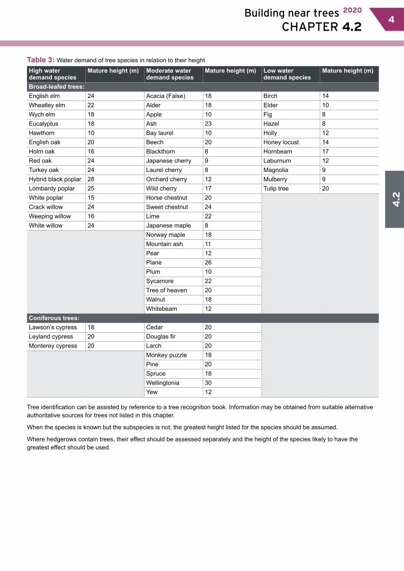
Table 3: Water demand of tree species in relation to their height
High water demand species
Mature height (m) Moderate water demand species
Mature height (m) Low water demand species
Mature height (m)
Broad-leafed trees:English elm 24 Acacia (False) 18 Birch 14Wheatley elm 22 Alder 18 Elder 10Wych elm 18 Apple 10 Fig 8Eucalyptus 18 Ash 23 Hazel 8Hawthorn 10 Bay laurel 10 Holly 12English oak 20 Beech 20 Honey locust 14Holm oak 16 Blackthorn 8 Hornbeam 17Red oak 24 Japanese cherry 9 Laburnum 12Turkey oak 24 Laurel cherry 8 Magnolia 9Hybrid black poplar 28 Orchard cherry 12 Mulberry 9Lombardy poplar 25 Wild cherry 17 Tulip tree 20White poplar 15 Horse chestnut 20Crack willow 24 Sweet chestnut 24Weeping willow 16 Lime 22White willow 24 Japanese maple 8
Norway maple 18Mountain ash 11Pear 12Plane 26Plum 10Sycamore 22Tree of heaven 20Walnut 18Whitebeam 12
Coniferous trees:Lawson’s cypress 18 Cedar 20Leyland cypress 20 Douglas fir 20Monterey cypress 20 Larch 20
Monkey puzzle 18Pine 20Spruce 18Wellingtonia 30Yew 12
Tree identification can be assisted by reference to a tree recognition book. Information may be obtained from suitable alternative authoritative sources for trees not listed in this chapter.
When the species is known but the subspecies is not, the greatest height listed for the species should be assumed.
Where hedgerows contain trees, their effect should be assessed separately and the height of the species likely to have the greatest effect should be used.
4.2
6 Building near trees 2020
CHAPTER 4.2 5
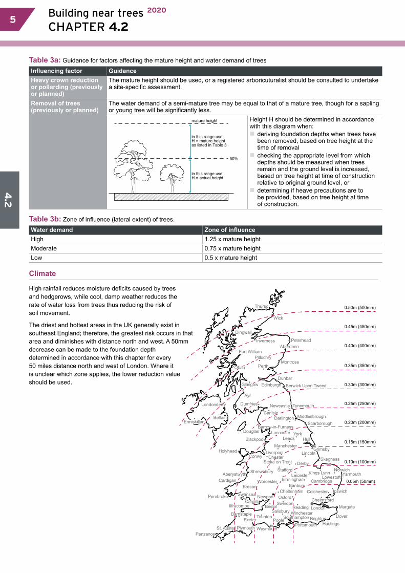
Table 3a: Guidance for factors affecting the mature height and water demand of trees
Influencing factor GuidanceHeavy crown reduction or pollarding (previously or planned)
The mature height should be used, or a registered arboricuturalist should be consulted to undertake a site-specific assessment.
Removal of trees (previously or planned)
The water demand of a semi-mature tree may be equal to that of a mature tree, though for a sapling or young tree will be significantly less.
mature height
in this range useH = mature heightas listed in Table 3
in this range use H = actual height
50%
Height H should be determined in accordance with this diagram when:�� deriving foundation depths when trees have been removed, based on tree height at the time of removal �� checking the appropriate level from which depths should be measured when trees remain and the ground level is increased, based on tree height at time of construction relative to original ground level, or�� determining if heave precautions are to be provided, based on tree height at time of construction.
Table 3b: Zone of influence (lateral extent) of trees.
Water demand Zone of influenceHigh 1.25 x mature heightModerate 0.75 x mature heightLow 0.5 x mature height
Climate
High rainfall reduces moisture deficits caused by trees and hedgerows, while cool, damp weather reduces the rate of water loss from trees thus reducing the risk of soil movement.
The driest and hottest areas in the UK generally exist in southeast England; therefore, the greatest risk occurs in that area and diminishes with distance north and west. A 50mm decrease can be made to the foundation depth determined in accordance with this chapter for every 50 miles distance north and west of London. Where it is unclear which zone applies, the lower reduction value should be used.
Swansea
Thurso
Wick
Dingwall
Inverness
Fort William
Oban
Pitlochry
Perth
Glasgow
Ayr
DumfriesLondonderry
Belfast
Douglas
Blackpool
HolyheadConwy
ShrewsburyAberystwyth
Lancaster
EdinburghDunbar
Berwick Upon Tweed
Newcastle Tynemouth
MiddlesbroughDarlingtonCarlisle
Montrose
Peterhead
Cardigan
Pembroke
Ilfracombe
ExeterTaunton
BristolSalisbury
Poole
WeymouthPlymouthPenzance
BreconWorcester Birmingham
Stafford
Stoke on TrentChester
LiverpoolManchester
Lincoln
Derby
Leicester Kings LynnNorwich
Skegness
Grimsby
HullYork
Scarborough
Leeds
YarmouthCambridge
BanburyCheltenham
OxfordSwindon
ReadingWinchester
SouthamptonHastings
Dover
MargateLondon
Chelmsford
Colchester
PortsmouthBrighton
NewportCardiff
St. Austell
EnniskillenBarrow-in-Furness
Aberdeen
Lowestoft
Ipswich
Barnstaple
0.50m (500mm)
0.45m (450mm)
0.40m (400mm)
0.35m (350mm)
0.30m (300mm)
0.25m (250mm)
0.20m (200mm)
0.15m (150mm)
0.10m (100mm)
0.05m (50mm)
4.2
Building near trees 2020
CHAPTER 4.2 76
4.2.5 Foundations in all soil typesFoundations in all soil types shall be appropriately designed and constructed to transmit loads to the ground safely and without excessive movement.
Different foundation types should not be used to support the same structure unless the foundation and superstructure design are undertaken by an engineer.
Freestanding masonry walls should be constructed on foundations in accordance with this chapter or designed to accommodate potential ground movement, for example, by careful use of movement joints and reinforcement.
4.2.6 Excavation of foundationsExcavation of foundations shall take account of the design and be suitable to receive concrete.
Where trench bottoms become excessively dried or softened due to rain or ground water, the excavation should be re-bottomed prior to concreting.
Foundation depths should be measured on the centre line of the excavation and from ground level determined from Clause 4.2.9.
Some root activity may be expected below the depths determined in accordance with this guidance. However, if significant quantities of roots are unexpectedly encountered in the base of the trench, an engineer should be consulted to determine if the excavation should be deepened.
4.2.7 Foundations in shrinkable soilsFoundations shall be capable of accommodating the effects of trees, shrubs and hedgerows on shrinkable soils without excessive movement. Items to be taken into account include: a) foundation typeb) distance between tree and foundation c) method of assessment of foundation depths
d) foundation depths related to the zone of influence of new tree planting
e) foundation depths related to new shrub planting.
Landscape and foundation designs should be compatible, and planting schedules produced by a qualified landscape architect or other suitably qualified person and agreed with the local planning authority before work commences on site.
Foundation typeFoundations to all permanent structures, including garages, porches and conservatories, should take account of the effects of soil desiccation. Foundation types that are acceptable in shrinkable soils include strip, trench fill, pier and beam, pile and beam, and raft, providing they:
�� are capable of supporting the applied loads without undue settlement
�� include suitable heave precautions.
Variations to the foundation depths derived from this chapter may be permitted where:
�� it is necessary to take account of local ground conditions �� other foundation depths are traditionally acceptable
�� designed in accordance with Technical Requirement R5.
Root barriers are not an acceptable alternative to the guidance given.
Distance between tree and foundationThe distance (D) between the centre of the trunk and the nearest face of the foundation should be used to derive the foundation depths.
D = 2m where trees which have been, or are to be, removed from within 2m of the face of the proposed foundation are less than 50% of the mature height as given in Table 3. This is to avoid a situation where, for example, a ‘sapling’ removed from the foundation line would otherwise require an unnecessarily deep foundation since the D/H value would always be zero, regardless of the height H of the tree.
Also see: Chapter 4.1, 4.3, 4.4, 4.5 and Technical Requirement R5
Also see: NHBC Foundation Depth Calculator App. www.nhbc.co.uk/apps
4.2
8 Building near trees 2020
CHAPTER 4.2 7
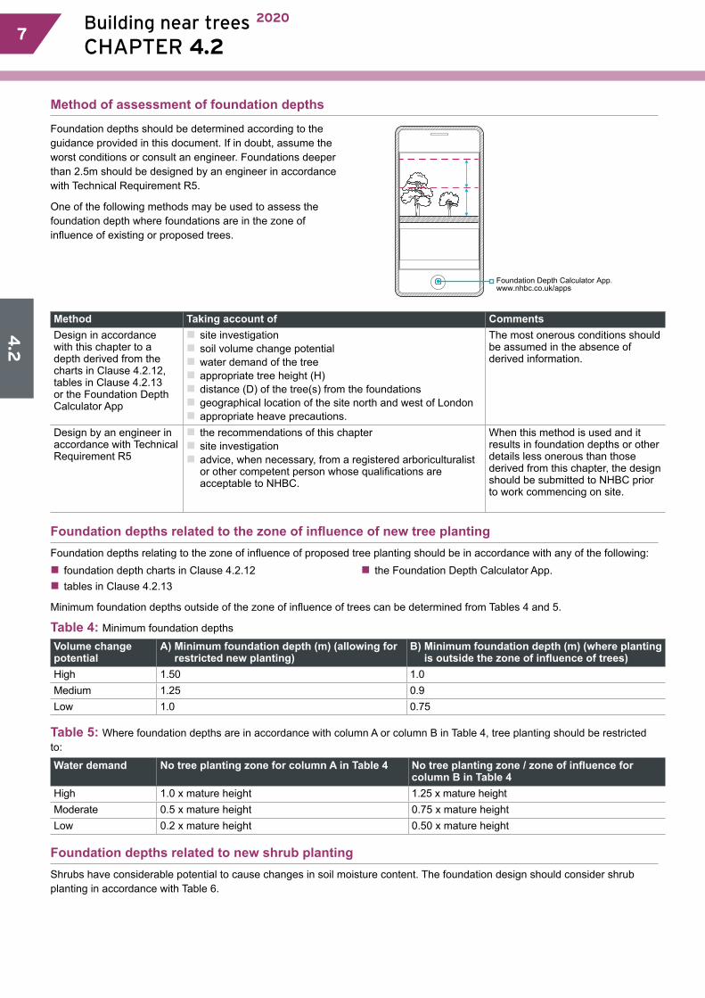
Method of assessment of foundation depths
Foundation depths should be determined according to the guidance provided in this document. If in doubt, assume the worst conditions or consult an engineer. Foundations deeper than 2.5m should be designed by an engineer in accordance with Technical Requirement R5.
One of the following methods may be used to assess the foundation depth where foundations are in the zone of influence of existing or proposed trees.
Foundation Depth Calculator App. www.nhbc.co.uk/apps
Method Taking account of CommentsDesign in accordance with this chapter to a depth derived from the charts in Clause 4.2.12, tables in Clause 4.2.13 or the Foundation Depth Calculator App
�� site investigation�� soil volume change potential�� water demand of the tree �� appropriate tree height (H)�� distance (D) of the tree(s) from the foundations �� geographical location of the site north and west of London�� appropriate heave precautions.
The most onerous conditions should be assumed in the absence of derived information.
Design by an engineer in accordance with Technical Requirement R5
�� the recommendations of this chapter �� site investigation�� advice, when necessary, from a registered arboriculturalist or other competent person whose qualifications are acceptable to NHBC.
When this method is used and it results in foundation depths or other details less onerous than those derived from this chapter, the design should be submitted to NHBC prior to work commencing on site.
Foundation depths related to the zone of influence of new tree plantingFoundation depths relating to the zone of influence of proposed tree planting should be in accordance with any of the following: �� foundation depth charts in Clause 4.2.12 �� tables in Clause 4.2.13
�� the Foundation Depth Calculator App.
Minimum foundation depths outside of the zone of influence of trees can be determined from Tables 4 and 5.
Table 4: Minimum foundation depths
Volume change potential
A) Minimum foundation depth (m) (allowing for restricted new planting)
B) Minimum foundation depth (m) (where planting is outside the zone of influence of trees)
High 1.50 1.0Medium 1.25 0.9Low 1.0 0.75
Table 5: Where foundation depths are in accordance with column A or column B in Table 4, tree planting should be restricted to:
Water demand No tree planting zone for column A in Table 4 No tree planting zone / zone of influence for column B in Table 4
High 1.0 x mature height 1.25 x mature heightModerate 0.5 x mature height 0.75 x mature heightLow 0.2 x mature height 0.50 x mature height
Foundation depths related to new shrub planting Shrubs have considerable potential to cause changes in soil moisture content. The foundation design should consider shrub planting in accordance with Table 6.
4.2
Building near trees 2020
CHAPTER 4.2 98
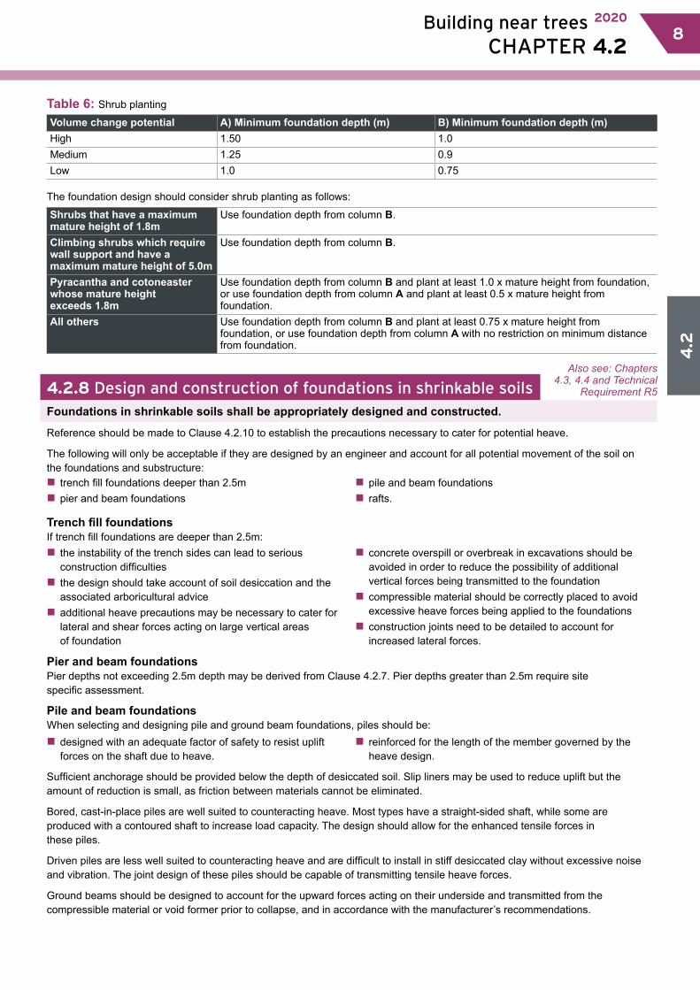
Table 6: Shrub planting
Volume change potential A) Minimum foundation depth (m) B) Minimum foundation depth (m) High 1.50 1.0Medium 1.25 0.9Low 1.0 0.75
The foundation design should consider shrub planting as follows:
Shrubs that have a maximum mature height of 1.8m
Use foundation depth from column B.
Climbing shrubs which require wall support and have a maximum mature height of 5.0m
Use foundation depth from column B.
Pyracantha and cotoneaster whose mature height exceeds 1.8m
Use foundation depth from column B and plant at least 1.0 x mature height from foundation, or use foundation depth from column A and plant at least 0.5 x mature height from foundation.
All others Use foundation depth from column B and plant at least 0.75 x mature height from foundation, or use foundation depth from column A with no restriction on minimum distance from foundation.
4.2.8 Design and construction of foundations in shrinkable soilsFoundations in shrinkable soils shall be appropriately designed and constructed.
Reference should be made to Clause 4.2.10 to establish the precautions necessary to cater for potential heave.
The following will only be acceptable if they are designed by an engineer and account for all potential movement of the soil on the foundations and substructure:�� trench fill foundations deeper than 2.5m�� pier and beam foundations
�� pile and beam foundations�� rafts.
Trench fill foundationsIf trench fill foundations are deeper than 2.5m:�� the instability of the trench sides can lead to serious construction difficulties�� the design should take account of soil desiccation and the associated arboricultural advice�� additional heave precautions may be necessary to cater for lateral and shear forces acting on large vertical areas of foundation
�� concrete overspill or overbreak in excavations should be avoided in order to reduce the possibility of additional vertical forces being transmitted to the foundation�� compressible material should be correctly placed to avoid excessive heave forces being applied to the foundations�� construction joints need to be detailed to account for increased lateral forces.
Pier and beam foundationsPier depths not exceeding 2.5m depth may be derived from Clause 4.2.7. Pier depths greater than 2.5m require site specific assessment.
Pile and beam foundationsWhen selecting and designing pile and ground beam foundations, piles should be:�� designed with an adequate factor of safety to resist uplift forces on the shaft due to heave.
�� reinforced for the length of the member governed by the heave design.
Sufficient anchorage should be provided below the depth of desiccated soil. Slip liners may be used to reduce uplift but the amount of reduction is small, as friction between materials cannot be eliminated.
Bored, cast-in-place piles are well suited to counteracting heave. Most types have a straight-sided shaft, while some are produced with a contoured shaft to increase load capacity. The design should allow for the enhanced tensile forces in these piles.
Driven piles are less well suited to counteracting heave and are difficult to install in stiff desiccated clay without excessive noise and vibration. The joint design of these piles should be capable of transmitting tensile heave forces.
Ground beams should be designed to account for the upward forces acting on their underside and transmitted from the compressible material or void former prior to collapse, and in accordance with the manufacturer’s recommendations.
Also see: Chapters 4.3, 4.4 and Technical
Requirement R5

4.2
10 Building near trees 2020
CHAPTER 4.2 9
Raft foundationsRaft foundations in shrinkable soils will only be acceptable where all of the following apply:�� design is by an engineer in accordance with Technical Requirement R5�� NHBC is satisfied that the raft is sufficiently stiff to resist differential movements�� NHBC is satisfied that the raft is founded on granular infill placed and fully compacted in layers and in accordance with the engineer’s specification. Where required by NHBC, site inspections are to be undertaken by the engineer to verify suitable compaction of the fill
�� the raft is generally rectangular in plan with a side ratio of not more than 2:1�� foundation depth is derived in accordance with Clause 4.2.7, and is less than 2.5m.
4.2.9 Foundation depths for specific conditions in shrinkable soilsFoundations in shrinkable soils shall be designed to transmit loads to the ground safely and without excessive movement. Items to be taken into account include: a) strip and trench fill foundations in non-shrinkable soils
overlying shrinkable soilb) measurement of foundation depths
c) granular infill beneath raft foundations in shrinkable soils
d) steps in foundations.
Strip and trench fill foundations in non-shrinkable soils overlying shrinkable soil Non shrinkable soils such as sands and gravels may overlie shrinkable soil. Foundations may be constructed on overlying non-shrinkable soil if all the following are satisfied:
�� conditions of Chapter 4.3 ‘Strip and trench fill foundations’ are met�� consistent soil conditions exist across each plot and this is confirmed by the site investigation�� depth of the non-shrinkable soil is greater than ¾ foundation depth X, where X is the foundation depth determined using charts in Clause 4.2.12, tables in Clause 4.2.13 or the Foundation Depth Calculator App, assuming all the soil is shrinkable�� the thickness T of non-shrinkable soil below the foundation is equal to, or more than, the width of the foundation B�� proposals are submitted to, and approved by, NHBC prior to work commencing on site.
shrinkable soilnon-shrinkable soil
acceptable foundation depth
BT equal to or greater than B
depth greater than ¾ X
depth X determined assumingshrinkable soil
Where any of the above are not met foundation depths should be determined as for shrinkable soil.
Measurement of foundation depths
Where ground levels are to remain unaltered, foundation depths should be measured from original ground level.
Measurement of foundation depths where ground levels are reduced or increased, either in the recent past or during construction, should be as shown in figures 1, 2 and 3.
Figure 1: Levels from which foundation depths are measured where trees or hedgerows are to remain
bb
a
tree to remain
tree to remain
original ground level
Use the lower of:a) foundation depth based on appropriate tree height (see Table 3a)b) foundation depth based on mature height of tree.
4.2
Building near trees 2020
CHAPTER 4.2 1110
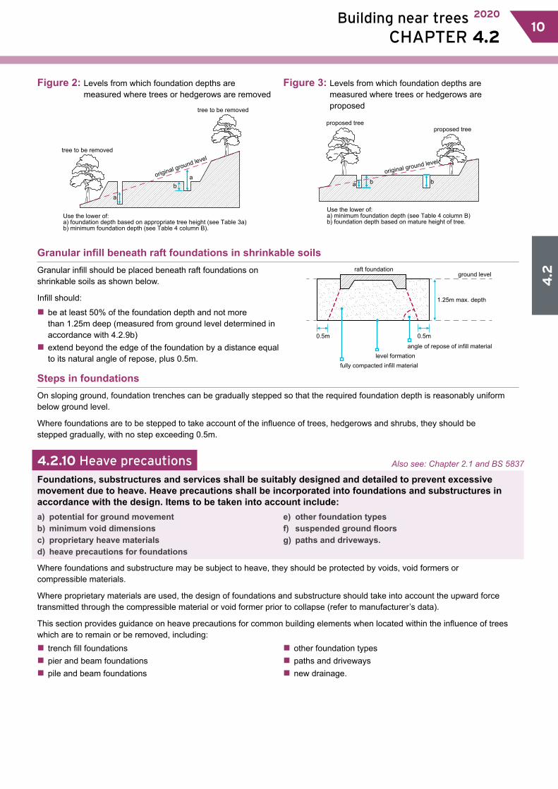
Figure 2: Levels from which foundation depths are measured where trees or hedgerows are removed
ba
a
tree to be removed
tree to be removed
original ground level
Use the lower of:a) foundation depth based on appropriate tree height (see Table 3a)b) minimum foundation depth (see Table 4 column B).
Figure 3: Levels from which foundation depths are measured where trees or hedgerows are proposed
Use the lower of:a) minimum foundation depth (see Table 4 column B)b) foundation depth based on mature height of tree.
proposed treeproposed tree
b ba
original ground level
Granular infill beneath raft foundations in shrinkable soilsGranular infill should be placed beneath raft foundations on shrinkable soils as shown below.
Infill should:
�� be at least 50% of the foundation depth and not more than 1.25m deep (measured from ground level determined in accordance with 4.2.9b)�� extend beyond the edge of the foundation by a distance equal to its natural angle of repose, plus 0.5m.
raft foundationground level
1.25m max. depth
0.5m 0.5m
fully compacted infill materiallevel formation
angle of repose of infill material
Steps in foundationsOn sloping ground, foundation trenches can be gradually stepped so that the required foundation depth is reasonably uniform below ground level.
Where foundations are to be stepped to take account of the influence of trees, hedgerows and shrubs, they should be stepped gradually, with no step exceeding 0.5m.
4.2.10 Heave precautionsFoundations, substructures and services shall be suitably designed and detailed to prevent excessive movement due to heave. Heave precautions shall be incorporated into foundations and substructures in accordance with the design. Items to be taken into account include:a) potential for ground movementb) minimum void dimensionsc) proprietary heave materialsd) heave precautions for foundations
e) other foundation typesf) suspended ground floors g) paths and driveways.
Where foundations and substructure may be subject to heave, they should be protected by voids, void formers or compressible materials.
Where proprietary materials are used, the design of foundations and substructure should take into account the upward force transmitted through the compressible material or void former prior to collapse (refer to manufacturer’s data).
This section provides guidance on heave precautions for common building elements when located within the influence of trees which are to remain or be removed, including:�� trench fill foundations�� pier and beam foundations�� pile and beam foundations
�� other foundation types�� paths and driveways�� new drainage.
Also see: Chapter 2.1 and BS 5837
4.2
12 Building near trees 2020
CHAPTER 4.2 11
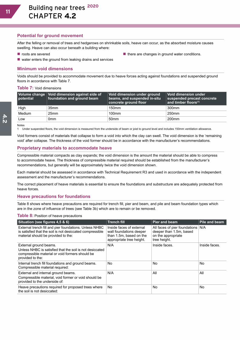
Potential for ground movementAfter the felling or removal of trees and hedgerows on shrinkable soils, heave can occur, as the absorbed moisture causes swelling. Heave can also occur beneath a building where:
�� roots are severed�� water enters the ground from leaking drains and services
�� there are changes in ground water conditions.
Minimum void dimensionsVoids should be provided to accommodate movement due to heave forces acting against foundations and suspended ground floors in accordance with Table 7.
Table 7: Void dimensions
Volume change potential
Void dimension against side of foundation and ground beam
Void dimension under ground beams, and suspended in-situ concrete ground floor
Void dimension under suspended precast concrete and timber floors(1)
High 35mm 150mm 300mmMedium 25mm 100mm 250mmLow 0mm 50mm 200mm
Notes1 Under suspended floors, the void dimension is measured from the underside of beam or joist to ground level and includes 150mm ventilation allowance.
Void formers consist of materials that collapse to form a void into which the clay can swell. The void dimension is the ‘remaining void’ after collapse. The thickness of the void former should be in accordance with the manufacturer’s recommendations.
Proprietary materials to accommodate heaveCompressible material compacts as clay expands; the void dimension is the amount the material should be able to compress to accommodate heave. The thickness of compressible material required should be established from the manufacturer’s recommendations, but generally will be approximately twice the void dimension shown.
Each material should be assessed in accordance with Technical Requirement R3 and used in accordance with the independent assessment and the manufacturer’s recommendations.
The correct placement of heave materials is essential to ensure the foundations and substructure are adequately protected from heave forces.
Heave precautions for foundationsTable 8 shows where heave precautions are required for trench fill, pier and beam, and pile and beam foundation types which are in the zone of influence of trees (see Table 3b) which are to remain or be removed.
Table 8: Position of heave precautions
Situation (see figures 4,5 & 6) Trench fill Pier and beam Pile and beamExternal trench fill and pier foundations. Unless NHBC is satisfied that the soil is not desiccated compressible material should be provided to the:
Inside faces of external wall foundations deeper than 1.5m, based on the appropriate tree height.
All faces of pier foundations deeper than 1.5m, based on the appropriate tree height.
N/A
External ground beams.Unless NHBC is satisfied that the soil is not desiccated compressible material or void formers should be provided to the:
N/A Inside faces. Inside faces.
Internal trench fill foundations and ground beams. Compressible material required:
No No No
External and internal ground beams. Compressible material, void former or void should be provided to the underside of:
N/A All All
Heave precautions required for proposed trees where the soil is not desiccated:
No No No
4.2
Building near trees 2020
CHAPTER 4.2 1312
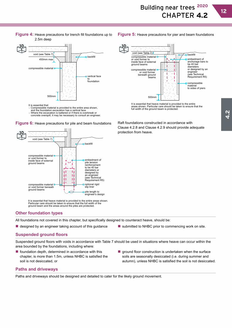
Figure 4: Heave precautions for trench fill foundations up to 2.5m deep
500mm
backfill
compressible material
450mm max
void (see Table 7)
It is essential that:■ Compressible material is provided to the entire area shown,
and the foundation excavation has a vertical face.■ Where the excavation is battered or if there is overbreak or
concrete overspill, it may be necessary to consult an engineer.
vertical face to foundation
Figure 5: Heave precautions for pier and beam foundations
500mm
backfillcompressible materialor void former toinside face of externalground beams
compressible materialor void former
beneath ground beams
void (see Table 7)
It is essential that heave material is provided to the entireareas shown. Particular care should be taken to ensure that thefull width of the ground beam is protected.
embedment ofanchorage bars tobe 40 bar diametersor designed by anengineer (see TechnicalRequirement R5)
compressible materialto sides of piers
Figure 6: Heave precautions for pile and beam foundations
backfill
compressible materialor void former toinside face of externalground beams
compressible materialor void former beneathground beams
void (see Table 7)
It is essential that heave material is provided to the entire areas shown. Particular care should be taken to ensure that the full width of the ground beam and the areas around the piles are protected.
embedment of pile tension reinforcement to be 40 bar diameters or designed byan engineer (see TechnicalRequirement R5)optional rigidslip liner
pile length toengineer's design
Raft foundations constructed in accordance with Clause 4.2.8 and Clause 4.2.9 should provide adequate protection from heave.
Other foundation typesAll foundations not covered in this chapter, but specifically designed to counteract heave, should be:
�� designed by an engineer taking account of this guidance �� submitted to NHBC prior to commencing work on site.
Suspended ground floorsSuspended ground floors with voids in accordance with Table 7 should be used in situations where heave can occur within the area bounded by the foundations, including where:�� foundation depth, determined in accordance with this chapter, is more than 1.5m, unless NHBC is satisfied the soil is not desiccated, or
�� ground floor construction is undertaken when the surface soils are seasonally desiccated (i.e. during summer and autumn), unless NHBC is satisfied the soil is not desiccated.
Paths and drivewaysPaths and driveways should be designed and detailed to cater for the likely ground movement.
3D 3D
3D
4.2
14 Building near trees 2020
CHAPTER 4.2 13
4.2.11 New drainageDrainage shall be in accordance with the design and allow for ground movement.
To protect against the effects of heave, drainage should be designed:
�� to take account of potential ground movement as shown in Table 9, including where pipes and services pass through substructure walls or foundations�� with gradients which may need to be greater than those in Chapter 5.3 ‘Drainage below ground’ as these do not account for possible ground movement
�� to use alternative means of catering for the movement when sufficient falls cannot be provided, for example by deepening the excavation and laying the pipework on a granular bedding of suitable thickness to reduce the extent of potential movement.
Table 9: Volume change potential
Volume change potential Potential ground movement (mm)High 150Medium 100Low 50
Note Existing land drains should be maintained or diverted.
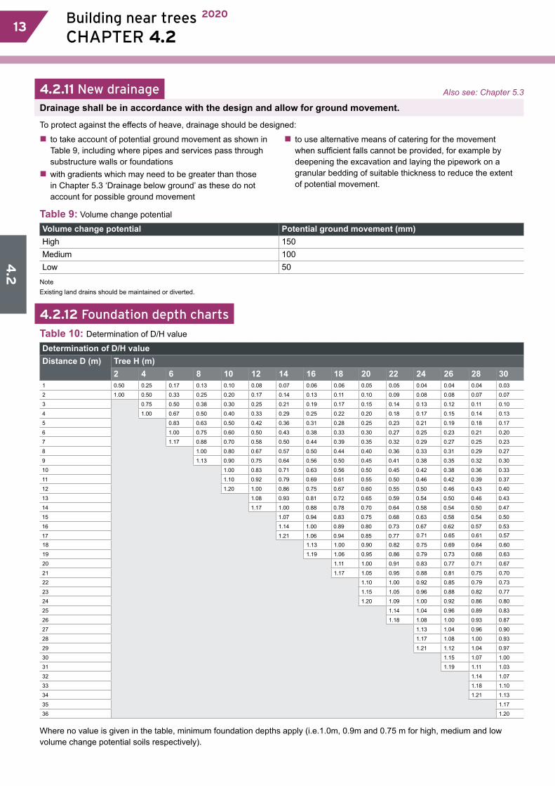
4.2.12 Foundation depth charts
Table 10: Determination of D/H value
Determination of D/H valueDistance D (m) Tree H (m)
2 4 6 8 10 12 14 16 18 20 22 24 26 28 301 0.50 0.25 0.17 0.13 0.10 0.08 0.07 0.06 0.06 0.05 0.05 0.04 0.04 0.04 0.03
2 1.00 0.50 0.33 0.25 0.20 0.17 0.14 0.13 0.11 0.10 0.09 0.08 0.08 0.07 0.07
3
0.75 0.50 0.38 0.30 0.25 0.21 0.19 0.17 0.15 0.14 0.13 0.12 0.11 0.10
4 1.00 0.67 0.50 0.40 0.33 0.29 0.25 0.22 0.20 0.18 0.17 0.15 0.14 0.13
5
0.83 0.63 0.50 0.42 0.36 0.31 0.28 0.25 0.23 0.21 0.19 0.18 0.17
6 1.00 0.75 0.60 0.50 0.43 0.38 0.33 0.30 0.27 0.25 0.23 0.21 0.20
7 1.17 0.88 0.70 0.58 0.50 0.44 0.39 0.35 0.32 0.29 0.27 0.25 0.23
8
1.00 0.80 0.67 0.57 0.50 0.44 0.40 0.36 0.33 0.31 0.29 0.27
9 1.13 0.90 0.75 0.64 0.56 0.50 0.45 0.41 0.38 0.35 0.32 0.30
10
1.00 0.83 0.71 0.63 0.56 0.50 0.45 0.42 0.38 0.36 0.33
11 1.10 0.92 0.79 0.69 0.61 0.55 0.50 0.46 0.42 0.39 0.37
12 1.20 1.00 0.86 0.75 0.67 0.60 0.55 0.50 0.46 0.43 0.40
13
1.08 0.93 0.81 0.72 0.65 0.59 0.54 0.50 0.46 0.43
14 1.17 1.00 0.88 0.78 0.70 0.64 0.58 0.54 0.50 0.47
15
1.07 0.94 0.83 0.75 0.68 0.63 0.58 0.54 0.50
16 1.14 1.00 0.89 0.80 0.73 0.67 0.62 0.57 0.53
17 1.21 1.06 0.94 0.85 0.77 0.71 0.65 0.61 0.57
18
1.13 1.00 0.90 0.82 0.75 0.69 0.64 0.60
19 1.19 1.06 0.95 0.86 0.79 0.73 0.68 0.63
20
1.11 1.00 0.91 0.83 0.77 0.71 0.67
21 1.17 1.05 0.95 0.88 0.81 0.75 0.70
22
1.10 1.00 0.92 0.85 0.79 0.73
23 1.15 1.05 0.96 0.88 0.82 0.77
24 1.20 1.09 1.00 0.92 0.86 0.80
25
1.14 1.04 0.96 0.89 0.83
26 1.18 1.08 1.00 0.93 0.87
27
1.13 1.04 0.96 0.90
28 1.17 1.08 1.00 0.93
29 1.21 1.12 1.04 0.97
30
1.15 1.07 1.00
31 1.19 1.11 1.03
32
1.14 1.07
33 1.18 1.10
34 1.21 1.13
35
1.17
36 1.20
Where no value is given in the table, minimum foundation depths apply (i.e.1.0m, 0.9m and 0.75 m for high, medium and low volume change potential soils respectively).
Also see: Chapter 5.3
4.2
Building near trees 2020
CHAPTER 4.2 1514
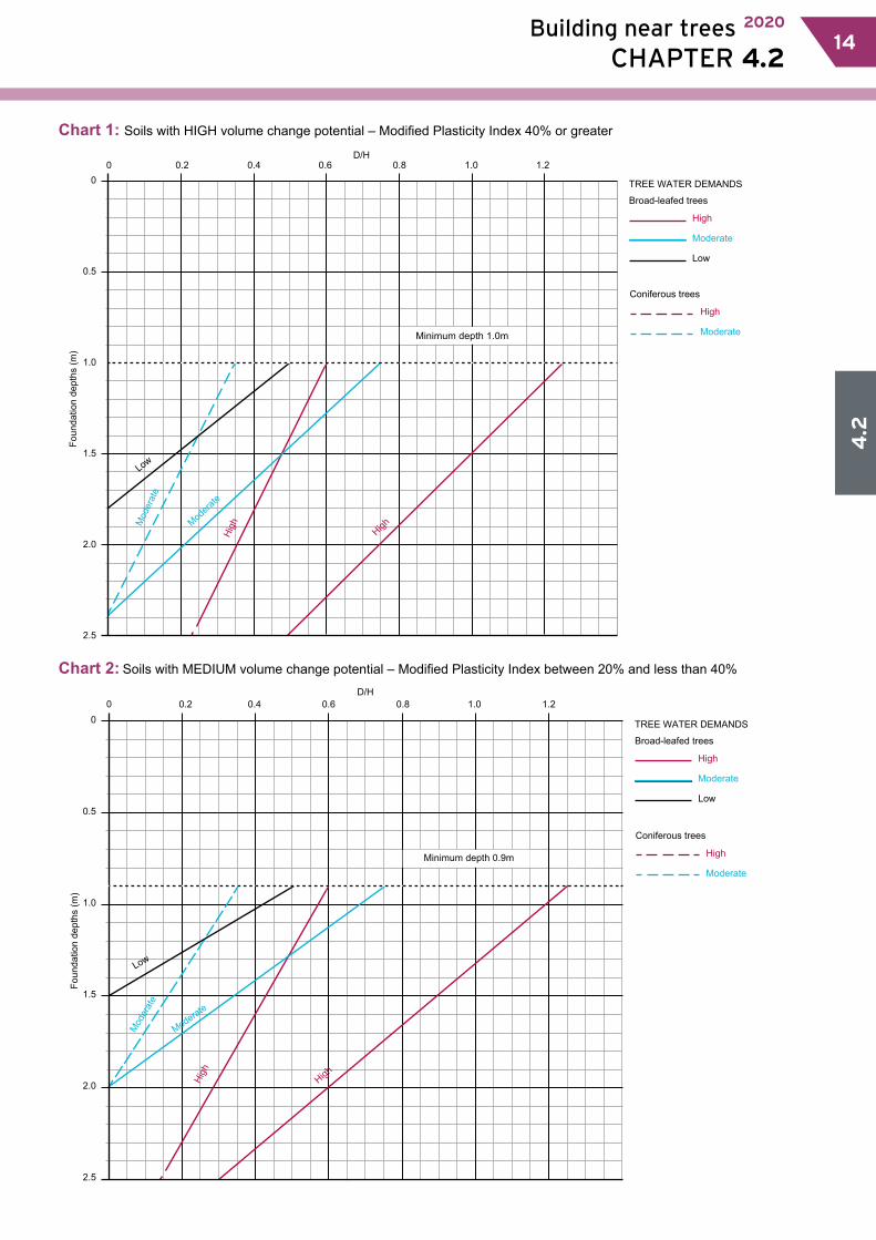
Chart 1: Soils with HIGH volume change potential – Modified Plasticity Index 40% or greater
0 0.2 0.4 0.6 0.8 1.0 1.20
0.5
1.0
1.5
2.0
2.5
Minimum depth 1.0m
Foun
datio
n de
pths
(m)
D/H
Low
Modera
te
Mod
erat
e
High
High
TREE WATER DEMANDS
Broad-leafed trees
Coniferous trees
High
Moderate
Low
High
Moderate
Chart 2: Soils with MEDIUM volume change potential – Modified Plasticity Index between 20% and less than 40%D/H
Low
Moderate
Mod
erat
e
High
High
Foun
datio
n de
pths
(m)
0.2 0.4 0.6 0.8 1.0 1.20
0.5
1.0
1.5
2.0
2.5
TREE WATER DEMANDS
Broad-leafed trees
Coniferous trees
High
Moderate
Low
High
ModerateMinimum depth 0.9m
0
4.2
16 Building near trees 2020
CHAPTER 4.2 15
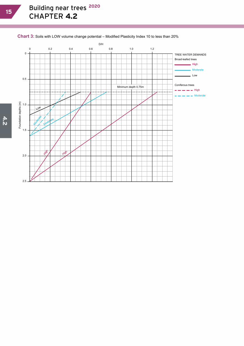
Chart 3: Soils with LOW volume change potential – Modified Plasticity Index 10 to less than 20%
D/H
Low
Moderate
Moder
ateHi
gh
High
Foun
datio
n de
pths
(m)
Minimum depth 0.75m
0.2 0.4 0.6 0.8 1.0 1.2
0
0.5
1.0
1.5
2.0
2.5
0
TREE WATER DEMANDS
Broad-leafed trees
Coniferous trees
High
Moderate
Low
High
Moderate
4.2
Building near trees 2020
CHAPTER 4.2 1716
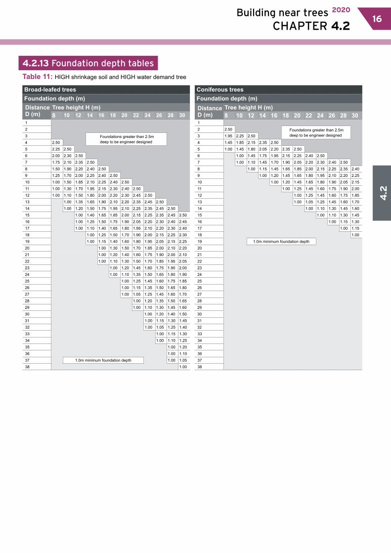
4.2.13 Foundation depth tables
Table 11: HIGH shrinkage soil and HIGH water demand tree
Broad-leafed treesFoundation depth (m)Distance D (m)
Tree height H (m)8 10 12 14 16 18 20 22 24 26 28 30
1
2
3 Foundations greater than 2.5m deep to be engineer designed
4 2.50
5 2.25 2.50
6 2.00 2.30 2.50
7 1.75 2.10 2.35 2.50
8 1.50 1.90 2.20 2.40 2.50
9 1.25 1.70 2.00 2.25 2.40 2.50
10 1.00 1.50 1.85 2.10 2.25 2.40 2.50
11 1.00 1.30 1.70 1.95 2.15 2.30 2.40 2.50
12 1.00 1.10 1.50 1.80 2.00 2.20 2.30 2.45 2.50
13 1.00 1.35 1.65 1.90 2.10 2.20 2.35 2.45 2.50
14 1.00 1.20 1.50 1.75 1.95 2.10 2.25 2.35 2.45 2.50
15 1.00 1.40 1.65 1.85 2.00 2.15 2.25 2.35 2.45 2.50
16 1.00 1.25 1.50 1.75 1.90 2.05 2.20 2.30 2.40 2.45
17 1.00 1.10 1.40 1.65 1.80 1.95 2.10 2.20 2.30 2.40
18 1.00 1.25 1.50 1.70 1.90 2.00 2.15 2.25 2.30
19 1.00 1.15 1.40 1.60 1.80 1.95 2.05 2.15 2.25
20 1.00 1.30 1.50 1.70 1.85 2.00 2.10 2.20
21 1.00 1.20 1.40 1.60 1.75 1.90 2.00 2.10
22 1.00 1.10 1.30 1.50 1.70 1.85 1.95 2.05
23 1.00 1.20 1.45 1.60 1.75 1.90 2.00
24 1.00 1.10 1.35 1.50 1.65 1.80 1.90
25 1.00 1.25 1.45 1.60 1.75 1.85
26 1.00 1.15 1.35 1.50 1.65 1.80
27 1.00 1.05 1.25 1.45 1.60 1.70
28 1.00 1.20 1.35 1.50 1.65
29 1.00 1.10 1.30 1.45 1.60
30 1.00 1.20 1.40 1.50
31 1.00 1.15 1.30 1.45
32 1.00 1.05 1.25 1.40
33 1.00 1.15 1.30
34 1.00 1.10 1.25
35 1.00 1.20
36 1.00 1.10
37 1.0m minimum foundation depth 1.00 1.05
38 1.00
Coniferous treesFoundation depth (m)Distance D (m)
Tree height H (m)8 10 12 14 16 18 20 22 24 26 28 30
1
2 2.50 Foundations greater than 2.5m deep to be engineer designed3 1.95 2.25 2.50
4 1.45 1.85 2.15 2.35 2.50
5 1.00 1.45 1.80 2.05 2.20 2.35 2.50
6 1.00 1.45 1.75 1.95 2.15 2.25 2.40 2.50
7 1.00 1.10 1.45 1.70 1.90 2.05 2.20 2.30 2.40 2.50
8 1.00 1.15 1.45 1.65 1.85 2.00 2.15 2.25 2.35 2.40
9 1.00 1.20 1.45 1.65 1.80 1.95 2.10 2.20 2.25
10 1.00 1.20 1.45 1.65 1.80 1.90 2.05 2.15
11 1.00 1.25 1.45 1.60 1.75 1.90 2.00
12 1.00 1.25 1.45 1.60 1.75 1.85
13 1.00 1.05 1.25 1.45 1.60 1.70
14 1.00 1.10 1.30 1.45 1.60
15 1.00 1.10 1.30 1.45
16 1.00 1.15 1.30
17 1.00 1.15
18 1.00
19 1.0m minimum foundation depth
20
21
22
23
24
25
26
27
28
29
30
31
32
33
34
35
36
37
38

4.2
18 Building near trees 2020
CHAPTER 4.2 17
Table 12: HIGH Shrinkage soil and MODERATE water demand tree
Broad-leafed treesFoundation depth (m)Distance D (m)
Tree height H (m)8 10 12 14 16 18 20 22 24 26 28 30
1 2.20 2.25 2.25 2.30 2.30 2.30 2.35 2.35 2.35 2.35 2.35 2.35
2 1.95 2.05 2.10 2.15 2.20 2.20 2.25 2.25 2.25 2.30 2.30 2.30
3 1.70 1.85 1.95 2.00 2.05 2.10 2.15 2.15 2.20 2.20 2.20 2.25
4 1.50 1.65 1.80 1.90 1.95 2.00 2.05 2.10 2.10 2.15 2.15 2.15
5 1.25 1.50 1.65 1.75 1.85 1.90 1.95 2.00 2.05 2.05 2.10 2.10
6 1.00 1.30 1.50 1.60 1.70 1.80 1.85 1.90 1.95 2.00 2.00 2.05
7 1.00 1.10 1.35 1.50 1.60 1.70 1.75 1.85 1.90 1.90 1.95 2.00
8 1.00 1.20 1.35 1.50 1.60 1.65 1.75 1.80 1.85 1.90 1.90
9 1.00 1.20 1.35 1.50 1.60 1.65 1.70 1.75 1.80 1.85
10 1.00 1.10 1.25 1.40 1.50 1.55 1.65 1.70 1.75 1.80
11 1.00 1.15 1.30 1.40 1.50 1.55 1.65 1.70 1.75
12 1.00 1.20 1.30 1.40 1.50 1.55 1.60 1.65
13 1.00 1.05 1.20 1.30 1.40 1.50 1.55 1.60
14 1.00 1.10 1.25 1.35 1.40 1.50 1.55
15 1.00 1.15 1.25 1.35 1.40 1.50
16 1.00 1.05 1.20 1.25 1.35 1.40
17 1.00 1.10 1.20 1.30 1.35
18 1.00 1.15 1.20 1.30
19 1.00 1.05 1.15 1.25
20 1.00 1.10 1.20
21 1.0m minimum foundation depth 1.00 1.10
22 1.00 1.05
23 1.00
Coniferous treesFoundation depth (m)Distance D (m)
Tree height H (m)8 10 12 14 16 18 20 22 24 26 28 30
1 1.90 2.00 2.10 2.15 2.15 2.20 2.20 2.25 2.25 2.25 2.30 2.30
2 1.40 1.60 1.75 1.85 1.90 2.00 2.00 2.05 2.10 2.10 2.15 2.15
3 1.00 1.20 1.40 1.55 1.65 1.75 1.80 1.85 1.90 1.95 2.00 2.00
4 1.00 1.10 1.30 1.40 1.55 1.60 1.70 1.75 1.80 1.85 1.90
5 1.00 1.00 1.15 1.30 1.40 1.50 1.60 1.65 1.70 1.75
6 1.00 1.10 1.20 1.35 1.40 1.50 1.55 1.60
7 1.00 1.00 1.15 1.25 1.35 1.40 1.50
8 1.00 1.10 1.20 1.30 1.35
9 1.00 1.05 1.15 1.20
10 1.00 1.00 1.10
11 1.00
12
13
14
15
16
17
18
19
20
21 1.0m minimum foundation depth
22
23
Table 13: HIGH shrinkage soil and LOW water demand tree
Broad-leafed treesFoundation depth (m)Distance D (m)
Tree height H (m)8 10 12 14 16 18 20 22 24 26 28 30
1 1.60 1.65 1.70 1.70 1.70 1.75 1.75 1.75 1.75 1.75 1.75 1.75
2 1.40 1.50 1.55 1.60 1.60 1.65 1.65 1.65 1.65 1.70 1.70 1.70
3 1.20 1.35 1.40 1.50 1.50 1.55 1.60 1.60 1.60 1.65 1.65 1.65
4 1.00 1.20 1.30 1.35 1.40 1.45 1.50 1.55 1.55 1.55 1.60 1.60
5 1.00 1.15 1.25 1.30 1.40 1.40 1.45 1.50 1.50 1.55 1.55
6 1.00 1.15 1.20 1.30 1.35 1.40 1.40 1.45 1.50 1.50
7 1.00 1.10 1.20 1.25 1.30 1.35 1.40 1.40 1.45
8 1.00 1.10 1.20 1.25 1.30 1.35 1.35 1.40
9 1.00 1.10 1.15 1.20 1.25 1.30 1.35
10 1.00 1.10 1.15 1.20 1.25 1.30
11 1.00 1.10 1.15 1.20 1.25
12 1.00 1.10 1.15 1.20
13 1.0m minimum foundation depth 1.00 1.10 1.15
14 1.00 1.05
15 1.00

4.2
Building near trees 2020
CHAPTER 4.2 1918
Table 14: MEDIUM shrinkage soil and HIGH water demand tree
Broad-leafed treesFoundation depth (m)Distance D (m)
Tree height H (m)8 10 12 14 16 18 20 22 24 26 28 30
1
2 Foundations greater than 2.5m deep to be engineer designed3 2.40 2.50
4 2.20 2.35 2.45
5 1.95 2.20 2.30 2.40 2.50
6 1.75 2.00 2.20 2.30 2.40 2.45 2.50
7 1.55 1.85 2.05 2.20 2.30 2.35 2.45 2.50
8 1.35 1.70 1.90 2.05 2.20 2.25 2.35 2.40 2.45 2.50
9 1.15 1.50 1.75 1.95 2.10 2.20 2.25 2.35 2.40 2.45 2.50 2.50
10 0.90 1.35 1.60 1.80 1.95 2.10 2.20 2.25 2.30 2.35 2.40 2.45
11 0.90 1.15 1.50 1.70 1.85 2.00 2.10 2.20 2.25 2.30 2.35 2.40
12 0.90 1.00 1.35 1.60 1.75 1.90 2.00 2.10 2.20 2.25 2.30 2.35
13 0.90 1.20 1.45 1.65 1.80 1.95 2.05 2.10 2.20 2.25 2.30
14 0.90 1.05 1.35 1.55 1.70 1.85 1.95 2.05 2.10 2.20 2.25
15 0.90 1.20 1.45 1.60 1.75 1.85 1.95 2.05 2.10 2.20
16 0.90 1.10 1.35 1.55 1.70 1.80 1.90 2.00 2.05 2.10
17 0.90 1.00 1.25 1.45 1.60 1.70 1.85 1.90 2.00 2.05
18 0.90 1.15 1.35 1.50 1.65 1.75 1.85 1.95 2.00
19 0.90 1.05 1.25 1.40 1.55 1.70 1.80 1.90 1.95
20 0.90 1.15 1.35 1.50 1.60 1.75 1.80 1.90
21 0.90 1.05 1.25 1.40 1.55 1.65 1.75 1.85
22 0.90 0.95 1.15 1.35 1.50 1.60 1.70 1.80
23 0.90 1.10 1.25 1.40 1.55 1.65 1.75
24 0.90 1.00 1.20 1.35 1.45 1.60 1.70
25 0.90 1.10 1.25 1.40 1.50 1.60
26 0.90 1.05 1.20 1.35 1.45 1.55
27 0.90 0.95 1.15 1.30 1.40 1.50
28 0.90 1.05 1.20 1.35 1.45
29 0.90 1.00 1.15 1.30 1.40
30 0.90 1.10 1.20 1.35
31 0.90 1.00 1.15 1.30
32 0.90 0.95 1.10 1.25
33 0.90 1.05 1.15
34 0.90 1.00 1.10
35 0.90 1.05
36 0.9m minimum foundation depth 0.90 1.00
37 0.90 0.95
38 0.90
Coniferous treesFoundation depth (m)Distance D (m)
Tree height H (m)8 10 12 14 16 18 20 22 24 26 28 30
1 Foundations greater than 2.5m deep to be engineer designed2 2.15 2.30 2.45 2.50
3 1.70 1.95 2.15 2.25 2.35 2.45 2.50
4 1.25 1.60 1.85 2.00 2.15 2.25 2.30 2.40 2.45 2.50 2.50
5 0.90 1.25 1.55 1.75 1.95 2.05 2.15 2.20 2.30 2.35 2.40 2.45
6 0.90 1.25 1.50 1.70 1.85 1.95 2.05 2.15 2.20 2.25 2.30
7 1.00 1.25 1.50 1.65 1.80 1.90 2.00 2.10 2.15 2.20
8 0.90 1.00 1.25 1.45 1.60 1.75 1.85 1.95 2.00 2.10
9 0.90 1.05 1.25 1.45 1.60 1.70 1.80 1.90 1.95
10 0.90 1.10 1.25 1.45 1.55 1.65 1.75 1.85
11 0.90 1.10 1.25 1.40 1.55 1.65 1.75
12 0.90 1.10 1.25 1.40 1.50 1.60
13 0.90 0.95 1.10 1.25 1.40 1.50
14 0.90 1.00 1.15 1.25 1.40
15 0.90 1.00 1.15 1.25
16 0.90 1.00 1.15
17 0.90 1.05
18 0.90
19
20
21
22
23
24
25
26
27
28
29
30
31
32
33
34
35
36 0.9m minimum foundation depth
37
38

4.2
20 Building near trees 2020
CHAPTER 4.2 19
Table 15: MEDIUM shrinkage soil and MODERATE water demand tree
Broad-leafed treesFoundation depth (m)Distance D (m)
Tree height H (m)8 10 12 14 16 18 20 22 24 26 28 30
1 1.85 1.85 1.90 1.90 1.95 1.95 1.95 1.95 1.95 1.95 1.95 1.95
2 1.65 1.75 1.80 1.80 1.85 1.85 1.85 1.90 1.90 1.90 1.90 1.90
3 1.45 1.60 1.65 1.70 1.75 1.80 1.80 1.80 1.85 1.85 1.85 1.85
4 1.30 1.45 1.55 1.60 1.65 1.70 1.75 1.75 1.80 1.80 1.80 1.80
5 1.10 1.30 1.40 1.50 1.55 1.60 1.65 1.70 1.70 1.75 1.75 1.80
6 0.90 1.15 1.30 1.40 1.45 1.55 1.60 1.60 1.65 1.70 1.70 1.75
7 0.90 1.00 1.15 1.30 1.40 1.45 1.50 1.55 1.60 1.65 1.65 1.70
8 0.90 1.05 1.20 1.30 1.35 1.45 1.50 1.55 1.55 1.60 1.65
9 0.90 1.10 1.20 1.30 1.35 1.40 1.45 1.50 1.55 1.60
10 0.90 0.95 1.10 1.20 1.30 1.35 1.40 1.45 1.50 1.55
11 0.90 1.00 1.10 1.20 1.30 1.35 1.40 1.45 1.50
12 0.90 1.05 1.15 1.20 1.30 1.35 1.40 1.45
13 0.90 0.95 1.05 1.15 1.25 1.30 1.35 1.40
14 0.90 1.00 1.10 1.15 1.25 1.30 1.35
15 0.90 1.00 1.10 1.15 1.25 1.30
16 0.90 0.95 1.05 1.10 1.20 1.25
17 0.90 1.00 1.10 1.15 1.20
18 0.90 1.00 1.10 1.15
19 0.90 0.95 1.00 1.10
20 0.90 0.95 1.05
21 0.9m minimum foundation depth 0.90 1.00
22 0.90 0.95
23 0.90
ConiferousFoundation depth (m)Distance D (m)
Tree height H (m)8 10 12 14 16 18 20 22 24 26 28 30
1 1.65 1.70 1.75 1.80 1.80 1.85 1.85 1.90 1.90 1.90 1.90 1.90
2 1.25 1.40 1.50 1.55 1.65 1.65 1.70 1.75 1.75 1.80 1.80 1.80
3 0.90 1.10 1.25 1.35 1.45 1.50 1.55 1.60 1.65 1.65 1.70 1.70
4 0.90 0.95 1.10 1.25 1.30 1.40 1.45 1.50 1.55 1.55 1.60
5 0.90 0.90 1.05 1.15 1.25 1.30 1.35 1.40 1.45 1.50
6 0.90 0.95 1.10 1.15 1.25 1.30 1.35 1.40
7 0.90 0.90 1.00 1.10 1.15 1.25 1.30
8 0.90 0.95 1.05 1.10 1.20
9 0.90 0.95 1.00 1.10
10 0.90 0.90 0.95
11 0.90
12
13
14
15
16
17
18
19
20
21 0.9m minimum foundation depth
22
23
Table 16: MEDIUM shrinkage soil and LOW water demand tree
Broad-leafed treesFoundation depth (m)Distance D (m)
Tree height H (m)8 10 12 14 16 18 20 22 24 26 28 30
1 1.35 1.40 1.40 1.45 1.45 1.45 1.45 1.45 1.45 1.45 1.50 1.50
2 1.20 1.30 1.30 1.35 1.35 1.40 1.40 1.40 1.40 1.45 1.45 1.45
3 1.05 1.15 1.20 1.25 1.30 1.30 1.35 1.35 1.35 1.40 1.40 1.40
4 0.90 1.05 1.10 1.20 1.20 1.25 1.30 1.30 1.30 1.35 1.35 1.35
5 0.90 1.00 1.10 1.15 1.20 1.20 1.25 1.25 1.30 1.30 1.30
6 0.90 1.00 1.05 1.10 1.15 1.20 1.20 1.25 1.25 1.30
7 0.90 1.00 1.05 1.10 1.15 1.15 1.20 1.20 1.25
8 0.90 1.00 1.05 1.10 1.10 1.15 1.20 1.20
9 0.90 1.00 1.05 1.05 1.10 1.15 1.15
10 0.90 0.95 1.00 1.05 1.10 1.10
11 0.90 0.95 1.00 1.05 1.10
12 0.90 0.95 1.00 1.05
13 0.9m minimum foundation depth 0.90 0.95 1.00
14 0.90 0.95
15 0.90
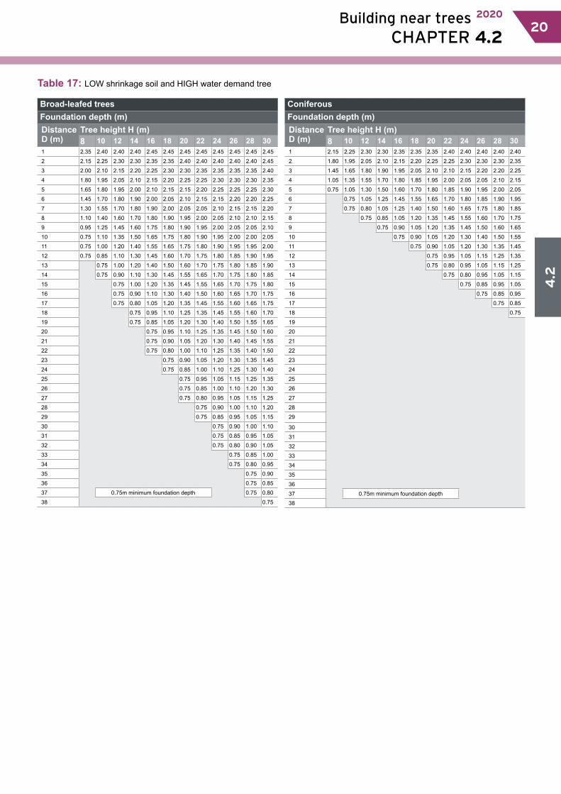
4.2
Building near trees 2020
CHAPTER 4.2 2120
Table 17: LOW shrinkage soil and HIGH water demand tree
Broad-leafed treesFoundation depth (m)Distance D (m)
Tree height H (m)8 10 12 14 16 18 20 22 24 26 28 30
1 2.35 2.40 2.40 2.40 2.45 2.45 2.45 2.45 2.45 2.45 2.45 2.45
2 2.15 2.25 2.30 2.30 2.35 2.35 2.40 2.40 2.40 2.40 2.40 2.45
3 2.00 2.10 2.15 2.20 2.25 2.30 2.30 2.35 2.35 2.35 2.35 2.40
4 1.80 1.95 2.05 2.10 2.15 2.20 2.25 2.25 2.30 2.30 2.30 2.35
5 1.65 1.80 1.95 2.00 2.10 2.15 2.15 2.20 2.25 2.25 2.25 2.30
6 1.45 1.70 1.80 1.90 2.00 2.05 2.10 2.15 2.15 2.20 2.20 2.25
7 1.30 1.55 1.70 1.80 1.90 2.00 2.05 2.05 2.10 2.15 2.15 2.20
8 1.10 1.40 1.60 1.70 1.80 1.90 1.95 2.00 2.05 2.10 2.10 2.15
9 0.95 1.25 1.45 1.60 1.75 1.80 1.90 1.95 2.00 2.05 2.05 2.10
10 0.75 1.10 1.35 1.50 1.65 1.75 1.80 1.90 1.95 2.00 2.00 2.05
11 0.75 1.00 1.20 1.40 1.55 1.65 1.75 1.80 1.90 1.95 1.95 2.00
12 0.75 0.85 1.10 1.30 1.45 1.60 1.70 1.75 1.80 1.85 1.90 1.95
13 0.75 1.00 1.20 1.40 1.50 1.60 1.70 1.75 1.80 1.85 1.90
14 0.75 0.90 1.10 1.30 1.45 1.55 1.65 1.70 1.75 1.80 1.85
15 0.75 1.00 1.20 1.35 1.45 1.55 1.65 1.70 1.75 1.80
16 0.75 0.90 1.10 1.30 1.40 1.50 1.60 1.65 1.70 1.75
17 0.75 0.80 1.05 1.20 1.35 1.45 1.55 1.60 1.65 1.75
18 0.75 0.95 1.10 1.25 1.35 1.45 1.55 1.60 1.70
19 0.75 0.85 1.05 1.20 1.30 1.40 1.50 1.55 1.65
20 0.75 0.95 1.10 1.25 1.35 1.45 1.50 1.60
21 0.75 0.90 1.05 1.20 1.30 1.40 1.45 1.55
22 0.75 0.80 1.00 1.10 1.25 1.35 1.40 1.50
23 0.75 0.90 1.05 1.20 1.30 1.35 1.45
24 0.75 0.85 1.00 1.10 1.25 1.30 1.40
25 0.75 0.95 1.05 1.15 1.25 1.35
26 0.75 0.85 1.00 1.10 1.20 1.30
27 0.75 0.80 0.95 1.05 1.15 1.25
28 0.75 0.90 1.00 1.10 1.20
29 0.75 0.85 0.95 1.05 1.15
30 0.75 0.90 1.00 1.10
31 0.75 0.85 0.95 1.05
32 0.75 0.80 0.90 1.05
33 0.75 0.85 1.00
34 0.75 0.80 0.95
35 0.75 0.90
36 0.75 0.85
37 0.75m minimum foundation depth 0.75 0.80
38 0.75
ConiferousFoundation depth (m)Distance D (m)
Tree height H (m)8 10 12 14 16 18 20 22 24 26 28 30
1 2.15 2.25 2.30 2.30 2.35 2.35 2.35 2.40 2.40 2.40 2.40 2.40
2 1.80 1.95 2.05 2.10 2.15 2.20 2.25 2.25 2.30 2.30 2.30 2.35
3 1.45 1.65 1.80 1.90 1.95 2.05 2.10 2.10 2.15 2.20 2.20 2.25
4 1.05 1.35 1.55 1.70 1.80 1.85 1.95 2.00 2.05 2.05 2.10 2.15
5 0.75 1.05 1.30 1.50 1.60 1.70 1.80 1.85 1.90 1.95 2.00 2.05
6 0.75 1.05 1.25 1.45 1.55 1.65 1.70 1.80 1.85 1.90 1.95
7 0.75 0.80 1.05 1.25 1.40 1.50 1.60 1.65 1.75 1.80 1.85
8 0.75 0.85 1.05 1.20 1.35 1.45 1.55 1.60 1.70 1.75
9 0.75 0.90 1.05 1.20 1.35 1.45 1.50 1.60 1.65
10 0.75 0.90 1.05 1.20 1.30 1.40 1.50 1.55
11 0.75 0.90 1.05 1.20 1.30 1.35 1.45
12 0.75 0.95 1.05 1.15 1.25 1.35
13 0.75 0.80 0.95 1.05 1.15 1.25
14 0.75 0.80 0.95 1.05 1.15
15 0.75 0.85 0.95 1.05
16 0.75 0.85 0.95
17 0.75 0.85
18 0.75
19
20
21
22
23
24
25
26
27
28
29
30
31
32
33
34
35
36
37 0.75m minimum foundation depth
38

4.2
22 Building near trees 2020
CHAPTER 4.2 21
Table 18: LOW shrinkage soil and MODERATE water demand tree
Broad-leafed treesFoundation depth (m)Distance D (m)
Tree height H (m)8 10 12 14 16 18 20 22 24 26 28 30
1 1.50 1.50 1.55 1.55 1.55 1.55 1.55 1.55 1.55 1.60 1.60 1.60
2 1.35 1.40 1.45 1.45 1.50 1.50 1.50 1.50 1.55 1.55 1.55 1.55
3 1.20 1.30 1.35 1.40 1.40 1.45 1.45 1.45 1.50 1.50 1.50 1.50
4 1.05 1.15 1.25 1.30 1.35 1.35 1.40 1.40 1.45 1.45 1.45 1.45
5 0.90 1.05 1.15 1.20 1.25 1.30 1.35 1.35 1.40 1.40 1.40 1.45
6 0.75 0.95 1.05 1.15 1.20 1.25 1.30 1.30 1.35 1.35 1.40 1.40
7 0.75 0.85 0.95 1.05 1.10 1.20 1.20 1.25 1.30 1.30 1.35 1.35
8 0.75 0.85 0.95 1.05 1.10 1.15 1.20 1.25 1.25 1.30 1.30
9 0.75 0.90 1.00 1.05 1.10 1.15 1.20 1.25 1.25 1.30
10 0.75 0.80 0.90 1.00 1.05 1.10 1.15 1.20 1.20 1.25
11 0.75 0.85 0.95 1.00 1.05 1.10 1.15 1.15 1.20
12 0.75 0.85 0.95 1.00 1.05 1.10 1.15 1.15
13 0.75 0.80 0.90 0.95 1.00 1.05 1.10 1.15
14 0.75 0.85 0.90 0.95 1.00 1.05 1.10
15 0.75 0.85 0.90 0.95 1.00 1.05
16 0.75 0.80 0.85 0.90 0.95 1.00
17 0.75 0.80 0.90 0.95 1.00
18 0.75 0.85 0.90 0.95
19 0.75 0.80 0.85 0.90
20 0.75 0.80 0.85
21 0.75m minimum foundation depth 0.75 0.85
22 0.75 0.80
23 0.75
ConiferousFoundation depth (m)Distance D (m)
Tree height H (m)8 10 12 14 16 18 20 22 24 26 28 30
1 1.30 1.40 1.40 1.45 1.45 1.50 1.50 1.50 1.50 1.55 1.55 1.55
2 1.00 1.15 1.20 1.25 1.30 1.35 1.40 1.40 1.40 1.45 1.45 1.45
3 0.75 0.90 1.00 1.10 1.15 1.20 1.25 1.30 1.30 1.35 1.35 1.40
4 0.75 0.80 0.95 1.00 1.10 1.15 1.20 1.20 1.25 1.25 1.30
5 0.75 0.75 0.85 0.95 1.00 1.05 1.10 1.15 1.20 1.20
6 0.75 0.80 0.90 0.95 1.00 1.05 1.10 1.15
7 0.75 0.75 0.85 0.90 0.95 1.00 1.05
8 0.75 0.80 0.85 0.95 0.95
9 0.75 0.80 0.85 0.90
10 0.75 0.75 0.80
11 0.75
12
13
14
15
16
17
18
19
20
21 0.75m minimum foundation depth
22
23
Table 19: LOW shrinkage soil and LOW water demand tree
Broad-leafed treesFoundation depth (m)Distance D (m)
Tree height H (m)8 10 12 14 16 18 20 22 24 26 28 30
1 1.10 1.15 1.15 1.15 1.15 1.15 1.20 1.20 1.20 1.20 1.20 1.20
2 1.00 1.05 1.05 1.10 1.10 1.10 1.15 1.15 1.15 1.15 1.15 1.15
3 0.90 0.95 1.00 1.05 1.05 1.05 1.10 1.10 1.10 1.10 1.10 1.15
4 0.75 0.85 0.90 0.95 1.00 1.00 1.05 1.05 1.05 1.10 1.10 1.10
5 0.75 0.85 0.90 0.95 0.95 1.00 1.00 1.05 1.05 1.05 1.05
6 0.75 0.85 0.90 0.90 0.95 0.95 1.00 1.00 1.05 1.05
7 0.75 0.85 0.85 0.90 0.95 0.95 1.00 1.00 1.00
8 0.75 0.80 0.85 0.90 0.90 0.95 0.95 1.00
9 0.75 0.80 0.85 0.90 0.90 0.95 0.95
10 0.75 0.80 0.85 0.85 0.90 0.90
11 0.75 0.80 0.85 0.85 0.90
12 0.75 0.80 0.85 0.85
13 0.75m minimum foundation depth 0.75 0.80 0.85
14 0.75 0.80
15 0.75
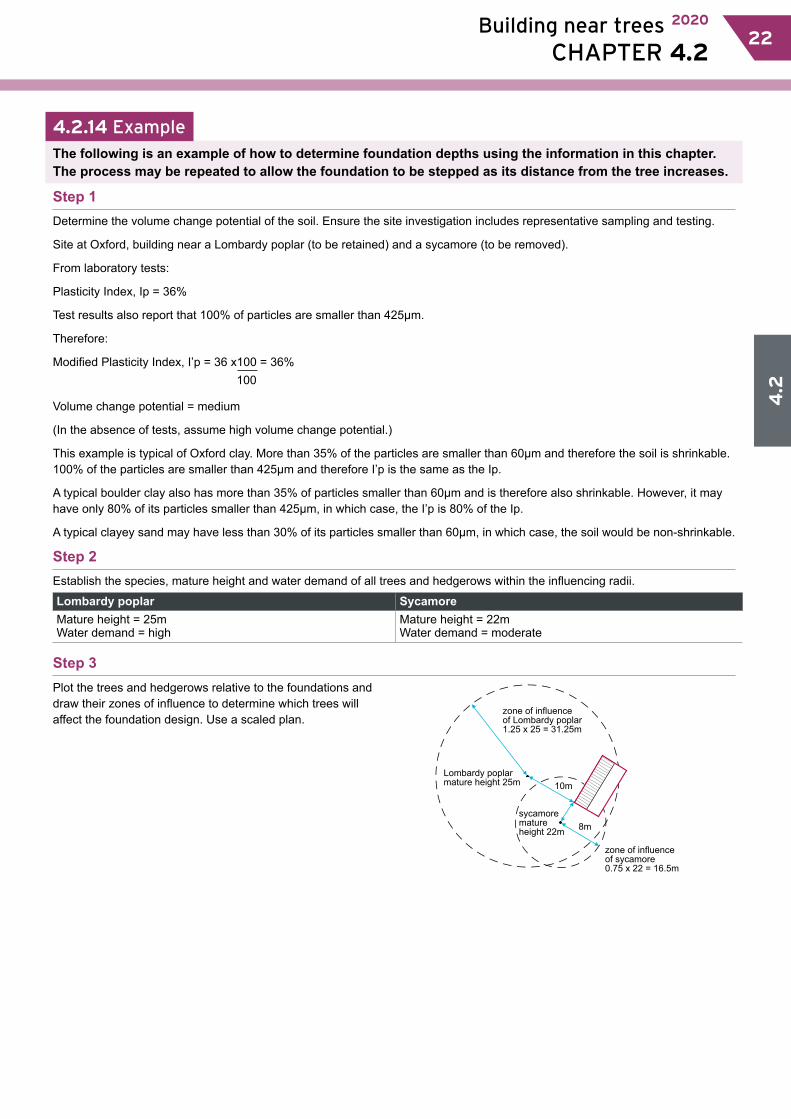
4.2
Building near trees 2020
CHAPTER 4.2 2322
4.2.14 ExampleThe following is an example of how to determine foundation depths using the information in this chapter.The process may be repeated to allow the foundation to be stepped as its distance from the tree increases.
Step 1Determine the volume change potential of the soil. Ensure the site investigation includes representative sampling and testing.
Site at Oxford, building near a Lombardy poplar (to be retained) and a sycamore (to be removed).
From laboratory tests:
Plasticity Index, Ip = 36%
Test results also report that 100% of particles are smaller than 425µm.
Therefore:
Modified Plasticity Index, I’p = 36 x100 = 36%
Volume change potential = medium
(In the absence of tests, assume high volume change potential.)
This example is typical of Oxford clay. More than 35% of the particles are smaller than 60µm and therefore the soil is shrinkable. 100% of the particles are smaller than 425µm and therefore I’p is the same as the Ip.
A typical boulder clay also has more than 35% of particles smaller than 60µm and is therefore also shrinkable. However, it may have only 80% of its particles smaller than 425µm, in which case, the I’p is 80% of the Ip.
A typical clayey sand may have less than 30% of its particles smaller than 60µm, in which case, the soil would be non-shrinkable.
Step 2Establish the species, mature height and water demand of all trees and hedgerows within the influencing radii.
Lombardy poplar SycamoreMature height = 25mWater demand = high
Mature height = 22mWater demand = moderate
Step 3Plot the trees and hedgerows relative to the foundations and draw their zones of influence to determine which trees will affect the foundation design. Use a scaled plan.
zone of influenceof Lombardy poplar1.25 x 25 = 31.25m
Lombardy poplarmature height 25m
sycamorematureheight 22m
zone of influenceof sycamore0.75 x 22 = 16.5m
10m
8m
100
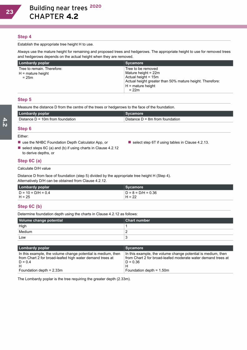
4.2
24 Building near trees 2020
CHAPTER 4.2 23
Step 4Establish the appropriate tree height H to use.
Always use the mature height for remaining and proposed trees and hedgerows. The appropriate height to use for removed trees and hedgerows depends on the actual height when they are removed.
Lombardy poplar SycamoreTree to remain. Therefore:H = mature height
= 25m
Tree to be removedMature height = 22mActual height = 15mActual height greater than 50% mature height. Therefore:H = mature height
= 22m
Step 5Measure the distance D from the centre of the trees or hedgerows to the face of the foundation.
Lombardy poplar SycamoreDistance D = 10m from foundation Distance D = 8m from foundation
Step 6Either:�� use the NHBC Foundation Depth Calculator App, or�� select steps 6C (a) and (b) if using charts in Clause 4.2.12 to derive depths, or
�� select step 6T if using tables in Clause 4.2.13.
Step 6C (a)Calculate D/H value
Distance D from face of foundation (step 5) divided by the appropriate tree height H (Step 4). Alternatively D/H can be obtained from Clause 4.2.12.
Lombardy poplar SycamoreD = 10 = D/H = 0.4H = 25
D = 8 = D/H = 0.36H = 22
Step 6C (b)Determine foundation depth using the charts in Clause 4.2.12 as follows:
Volume change potential Chart numberHigh 1Medium 2Low 3
Lombardy poplar SycamoreIn this example, the volume change potential is medium, then from Chart 2 for broad-leafed high water demand trees at D = 0.4HFoundation depth = 2.33m
In this example, the volume change potential is medium, then from Chart 2 for broad-leafed moderate water demand trees atD = 0.36HFoundation depth = 1.50m
The Lombardy poplar is the tree requiring the greater depth (2.33m).
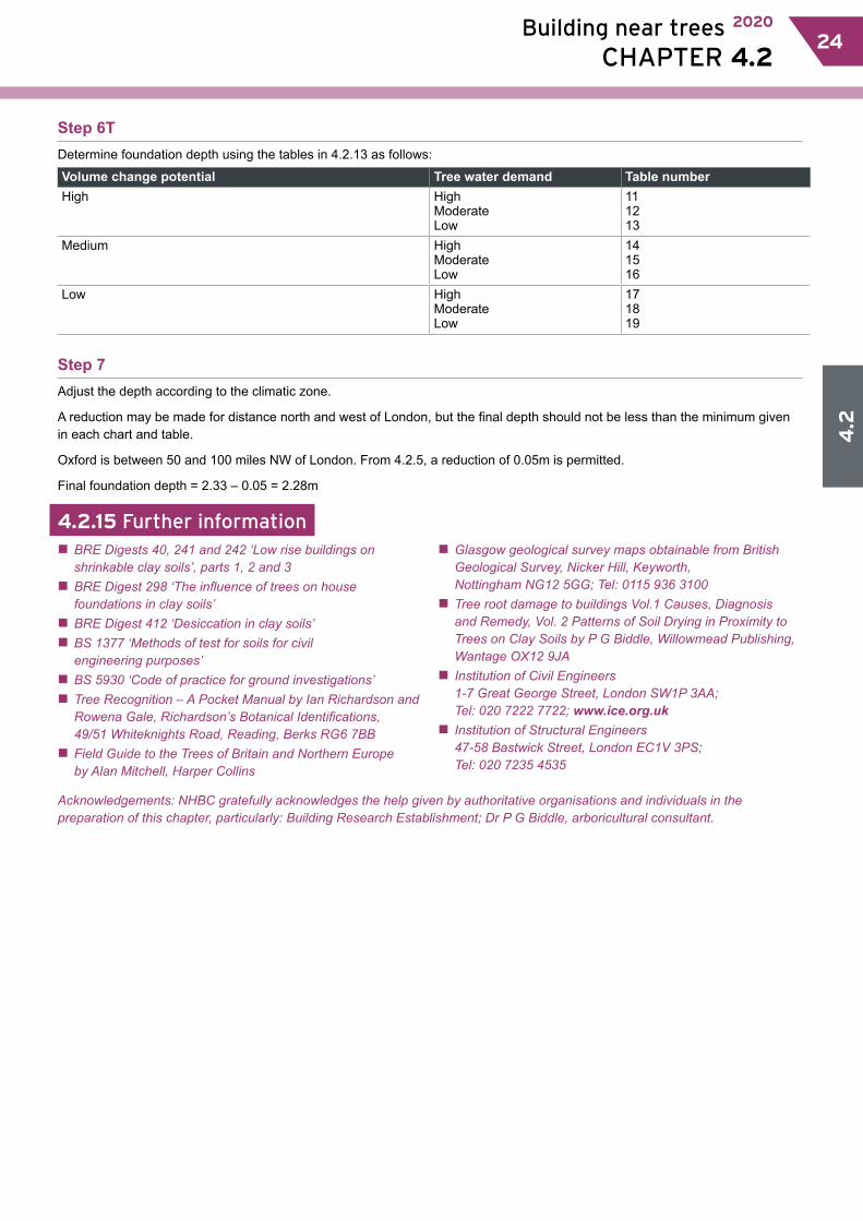
4.2
Building near trees 2020
CHAPTER 4.2 2524
Step 6TDetermine foundation depth using the tables in 4.2.13 as follows:
Volume change potential Tree water demand Table numberHigh High
ModerateLow
111213
Medium HighModerateLow
141516
Low HighModerateLow
171819
Step 7Adjust the depth according to the climatic zone.
A reduction may be made for distance north and west of London, but the final depth should not be less than the minimum given in each chart and table.
Oxford is between 50 and 100 miles NW of London. From 4.2.5, a reduction of 0.05m is permitted.
Final foundation depth = 2.33 – 0.05 = 2.28m
4.2.15 Further information�� BRE Digests 40, 241 and 242 ‘Low rise buildings on shrinkable clay soils’, parts 1, 2 and 3 �� BRE Digest 298 ‘The influence of trees on house foundations in clay soils’ �� BRE Digest 412 ‘Desiccation in clay soils’ �� BS 1377 ‘Methods of test for soils for civil engineering purposes’ �� BS 5930 ‘Code of practice for ground investigations’ �� Tree Recognition – A Pocket Manual by Ian Richardson and Rowena Gale, Richardson’s Botanical Identifications, 49/51 Whiteknights Road, Reading, Berks RG6 7BB �� Field Guide to the Trees of Britain and Northern Europe by Alan Mitchell, Harper Collins
�� Glasgow geological survey maps obtainable from British Geological Survey, Nicker Hill, Keyworth, Nottingham NG12 5GG; Tel: 0115 936 3100 �� Tree root damage to buildings Vol.1 Causes, Diagnosis and Remedy, Vol. 2 Patterns of Soil Drying in Proximity to Trees on Clay Soils by P G Biddle, Willowmead Publishing, Wantage OX12 9JA �� Institution of Civil Engineers 1-7 Great George Street, London SW1P 3AA; Tel: 020 7222 7722; www.ice.org.uk �� Institution of Structural Engineers 47-58 Bastwick Street, London EC1V 3PS; Tel: 020 7235 4535
Acknowledgements: NHBC gratefully acknowledges the help given by authoritative organisations and individuals in the preparation of this chapter, particularly: Building Research Establishment; Dr P G Biddle, arboricultural consultant.
4.3.1 Compliance 014.3.2 Provisionofinformation 014.3.3 Groundconditions 014.3.4 Hazardousground 024.3.5 Settingout 024.3.6 Servicesanddrainage 034.3.7 Safetransmissionofloads 034.3.8 Slopinggroundand steppedfoundations 054.3.9 Excavations 054.3.10 Reinforcement 064.3.11 Concrete 064.3.12 Movementjoints 064.3.13 Constructionjoints 06
This chapter gives guidance on meeting the Technical Requirements for strip and trench fill foundations.
Strip and trench fill foundations
CHAPTER 4.3
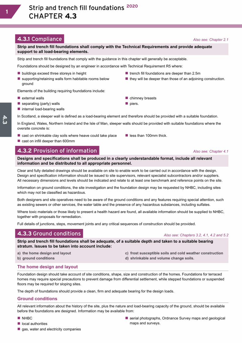
4.3
1 Strip and trench fill foundations 2020
CHAPTER 4.3 1
4.3.1 Compliance Also see: Chapter 2.1
Strip and trench fill foundations shall comply with the Technical Requirements and provide adequate support to all load-bearing elements.
Strip and trench fill foundations that comply with the guidance in this chapter will generally be acceptable.
Foundations should be designed by an engineer in accordance with Technical Requirement R5 where:
�� buildings exceed three storeys in height�� supporting/retaining walls form habitable rooms below ground
�� trench fill foundations are deeper than 2.5m�� they will be deeper than those of an adjoining construction.
Elements of the building requiring foundations include:
�� external walls�� separating (party) walls�� internal load-bearing walls
�� chimney breasts�� piers.
In Scotland, a sleeper wall is defined as a load-bearing element and therefore should be provided with a suitable foundation.
In England, Wales, Northern Ireland and the Isle of Man, sleeper walls should be provided with suitable foundations where the oversite concrete is:
�� cast on shrinkable clay soils where heave could take place�� cast on infill deeper than 600mm
�� less than 100mm thick.
4.3.2 Provision of information Also see: Chapter 4.1
Designs and specifications shall be produced in a clearly understandable format, include all relevant information and be distributed to all appropriate personnel.
Clear and fully detailed drawings should be available on site to enable work to be carried out in accordance with the design. Design and specification information should be issued to site supervisors, relevant specialist subcontractors and/or suppliers. All necessary dimensions and levels should be indicated and relate to at least one benchmark and reference points on the site.
Information on ground conditions, the site investigation and the foundation design may be requested by NHBC, including sites which may not be classified as hazardous.
Both designers and site operatives need to be aware of the ground conditions and any features requiring special attention, such as existing sewers or other services, the water table and the presence of any hazardous substances, including sulfates.
Where toxic materials or those likely to present a health hazard are found, all available information should be supplied to NHBC, together with proposals for remediation.
Full details of junctions, steps, movement joints and any critical sequences of construction should be provided.
4.3.3 Ground conditions Also see: Chapters 3.2, 4.1, 4.2 and 5.2
Strip and trench fill foundations shall be adequate, of a suitable depth and taken to a suitable bearing stratum. Issues to be taken into account include:a) the home design and layout b) ground conditions
c) frost susceptible soils and cold weather constructiond) shrinkable and volume change soils.
The home design and layoutFoundation design should take account of site conditions, shape, size and construction of the homes. Foundations for terraced homes may require special precautions to prevent damage from differential settlement, while stepped foundations or suspended floors may be required for sloping sites.
The depth of foundations should provide a clean, firm and adequate bearing for the design loads.
Ground conditionsAll relevant information about the history of the site, plus the nature and load-bearing capacity of the ground, should be available before the foundations are designed. Information may be available from:
�� NHBC�� local authorities�� gas, water and electricity companies
�� aerial photographs, Ordnance Survey maps and geological maps and surveys.
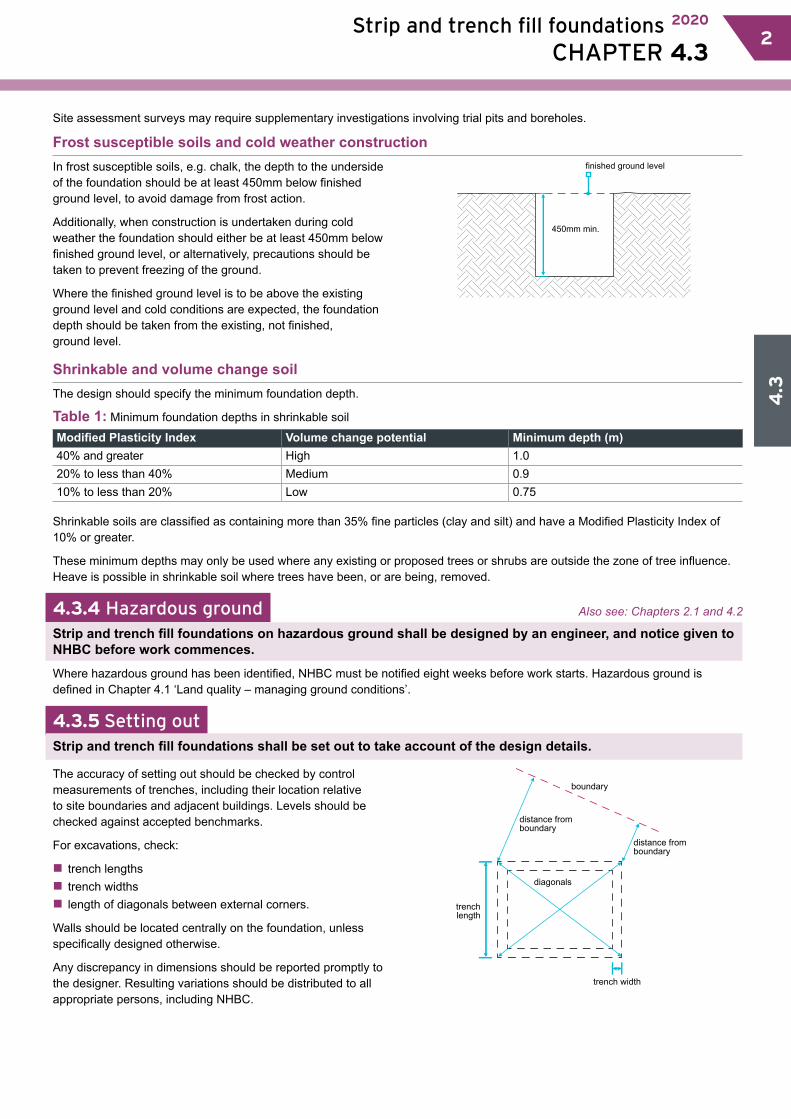
4.3
Strip and trench fill foundations 2020
CHAPTER 4.3 22
Site assessment surveys may require supplementary investigations involving trial pits and boreholes.
Frost susceptible soils and cold weather constructionIn frost susceptible soils, e.g. chalk, the depth to the underside of the foundation should be at least 450mm below finished ground level, to avoid damage from frost action.
Additionally, when construction is undertaken during cold weather the foundation should either be at least 450mm below finished ground level, or alternatively, precautions should be taken to prevent freezing of the ground.
Where the finished ground level is to be above the existing ground level and cold conditions are expected, the foundation depth should be taken from the existing, not finished, ground level.
finished ground level
450mm min.
Shrinkable and volume change soilThe design should specify the minimum foundation depth.
Table 1: Minimum foundation depths in shrinkable soil
Modified Plasticity Index Volume change potential Minimum depth (m)40% and greater High 1.020% to less than 40% Medium 0.910% to less than 20% Low 0.75
Shrinkable soils are classified as containing more than 35% fine particles (clay and silt) and have a Modified Plasticity Index of 10% or greater.
These minimum depths may only be used where any existing or proposed trees or shrubs are outside the zone of tree influence. Heave is possible in shrinkable soil where trees have been, or are being, removed.
4.3.4 Hazardous ground Also see: Chapters 2.1 and 4.2
Strip and trench fill foundations on hazardous ground shall be designed by an engineer, and notice given to NHBC before work commences.
Where hazardous ground has been identified, NHBC must be notified eight weeks before work starts. Hazardous ground is defined in Chapter 4.1 ‘Land quality – managing ground conditions’.
4.3.5 Setting outStrip and trench fill foundations shall be set out to take account of the design details.
The accuracy of setting out should be checked by control measurements of trenches, including their location relative to site boundaries and adjacent buildings. Levels should be checked against accepted benchmarks.
For excavations, check:
�� trench lengths�� trench widths�� length of diagonals between external corners.
Walls should be located centrally on the foundation, unless specifically designed otherwise.
Any discrepancy in dimensions should be reported promptly to the designer. Resulting variations should be distributed to all appropriate persons, including NHBC.
trenchlength
distance fromboundary
distance fromboundary
trench width
boundary
diagonals
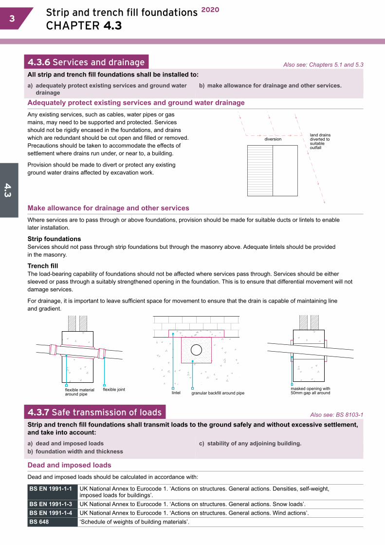
4.3
3 Strip and trench fill foundations 2020
CHAPTER 4.3 3
4.3.6 Services and drainage Also see: Chapters 5.1 and 5.3
All strip and trench fill foundations shall be installed to:a) adequately protect existing services and ground water
drainageb) make allowance for drainage and other services.
Adequately protect existing services and ground water drainageAny existing services, such as cables, water pipes or gas mains, may need to be supported and protected. Services should not be rigidly encased in the foundations, and drains which are redundant should be cut open and filled or removed. Precautions should be taken to accommodate the effects of settlement where drains run under, or near to, a building.
Provision should be made to divert or protect any existing ground water drains affected by excavation work.
land drainsdiverted tosuitableoutfall
diversion
Make allowance for drainage and other servicesWhere services are to pass through or above foundations, provision should be made for suitable ducts or lintels to enable later installation.
Strip foundations Services should not pass through strip foundations but through the masonry above. Adequate lintels should be provided in the masonry.
Trench fillThe load-bearing capability of foundations should not be affected where services pass through. Services should be either sleeved or pass through a suitably strengthened opening in the foundation. This is to ensure that differential movement will not damage services.
For drainage, it is important to leave sufficient space for movement to ensure that the drain is capable of maintaining line and gradient.
lintel granular backfill around pipeflexible materialaround pipe
flexible joint masked opening with50mm gap all around
4.3.7 Safe transmission of loads Also see: BS 8103-1
Strip and trench fill foundations shall transmit loads to the ground safely and without excessive settlement, and take into account:a) dead and imposed loadsb) foundation width and thickness
c) stability of any adjoining building.
Dead and imposed loadsDead and imposed loads should be calculated in accordance with:
BS EN 1991-1-1 UK National Annex to Eurocode 1. ‘Actions on structures. General actions. Densities, self-weight, imposed loads for buildings’.
BS EN 1991-1-3 UK National Annex to Eurocode 1. ‘Actions on structures. General actions. Snow loads’.BS EN 1991-1-4 UK National Annex to Eurocode 1. ‘Actions on structures. General actions. Wind actions’.BS 648 ‘Schedule of weights of building materials’.
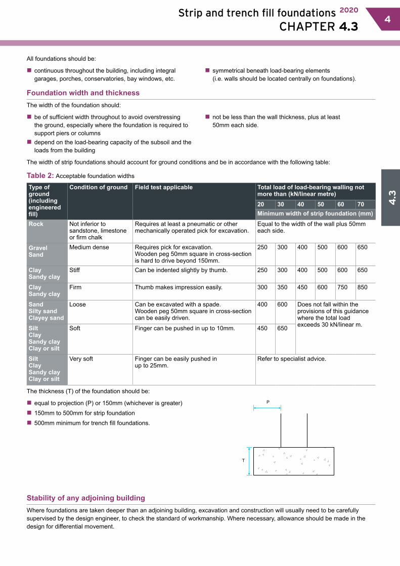
4.3
Strip and trench fill foundations 2020
CHAPTER 4.3 44
All foundations should be:
�� continuous throughout the building, including integral garages, porches, conservatories, bay windows, etc.
�� symmetrical beneath load-bearing elements (i.e. walls should be located centrally on foundations).
Foundation width and thicknessThe width of the foundation should:
�� be of sufficient width throughout to avoid overstressing the ground, especially where the foundation is required to support piers or columns�� depend on the load-bearing capacity of the subsoil and the loads from the building
�� not be less than the wall thickness, plus at least 50mm each side.
The width of strip foundations should account for ground conditions and be in accordance with the following table:
Table 2: Acceptable foundation widths
Type of ground(including engineered fill)
Condition of ground Field test applicable Total load of load-bearing walling not more than (kN/linear metre)20 30 40 50 60 70Minimum width of strip foundation (mm)
Rock Not inferior to sandstone, limestone or firm chalk
Requires at least a pneumatic or other mechanically operated pick for excavation.
Equal to the width of the wall plus 50mm each side.
Gravel �Sand
Medium dense Requires pick for excavation. Wooden peg 50mm square in cross-section is hard to drive beyond 150mm.
250 300 400 500 600 650
Clay Sandy clay
Stiff Can be indented slightly by thumb. 250 300 400 500 600 650
Clay Sandy clay
Firm Thumb makes impression easily. 300 350 450 600 750 850
Sand Silty sand Clayey sand
Loose Can be excavated with a spade. Wooden peg 50mm square in cross-section can be easily driven.
400 600 Does not fall within the provisions of this guidance where the total load exceeds 30 kN/linear m.Silt
Clay Sandy clay Clay or silt
Soft Finger can be pushed in up to 10mm. 450 650
Silt Clay Sandy clay Clay or silt
Very soft Finger can be easily pushed in up to 25mm.
Refer to specialist advice.
The thickness (T) of the foundation should be:
�� equal to projection (P) or 150mm (whichever is greater) �� 150mm to 500mm for strip foundation�� 500mm minimum for trench fill foundations.
T
P
Stability of any adjoining buildingWhere foundations are taken deeper than an adjoining building, excavation and construction will usually need to be carefully supervised by the design engineer, to check the standard of workmanship. Where necessary, allowance should be made in the design for differential movement.
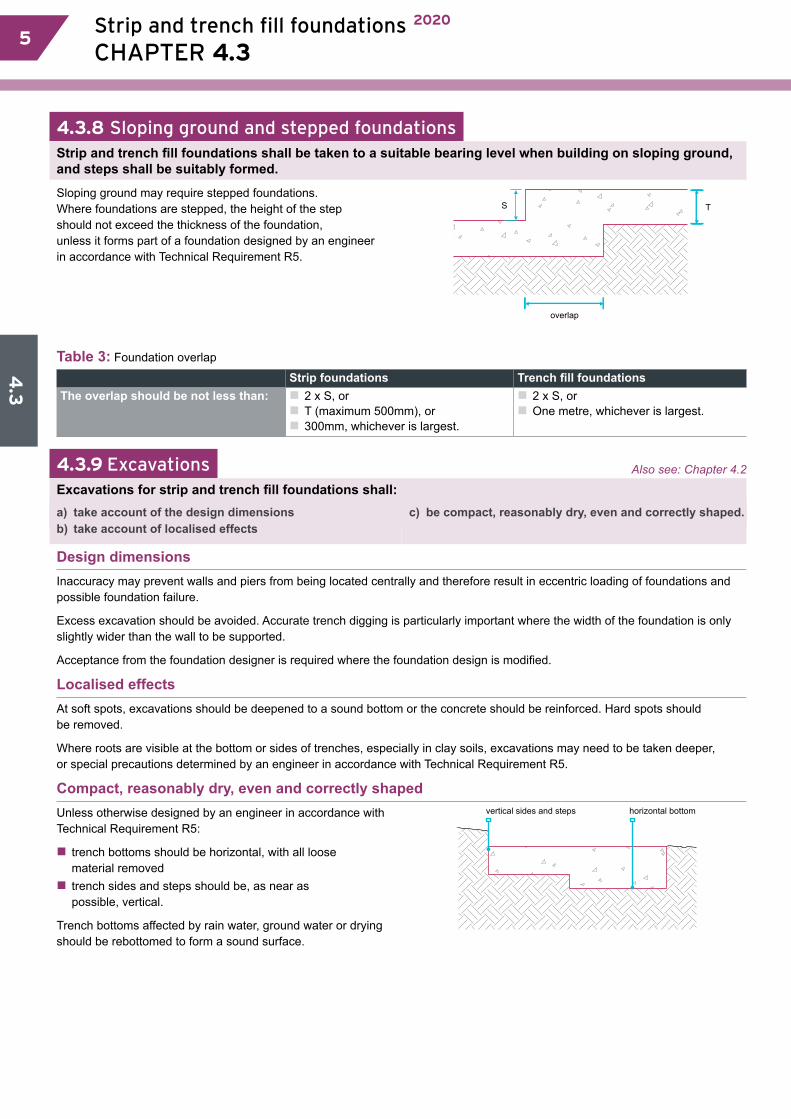
4.3
5 Strip and trench fill foundations 2020
CHAPTER 4.3 5
4.3.8 Sloping ground and stepped foundationsStrip and trench fill foundations shall be taken to a suitable bearing level when building on sloping ground, and steps shall be suitably formed.
Sloping ground may require stepped foundations. Where foundations are stepped, the height of the step should not exceed the thickness of the foundation, unless it forms part of a foundation designed by an engineer in accordance with Technical Requirement R5.
S T
overlap
Table 3: Foundation overlap
Strip foundations Trench fill foundationsThe overlap should be not less than: �� 2 x S, or
�� T (maximum 500mm), or�� 300mm, whichever is largest.
�� 2 x S, or�� One metre, whichever is largest.
4.3.9 Excavations Also see: Chapter 4.2
Excavations for strip and trench fill foundations shall:a) take account of the design dimensionsb) take account of localised effects
c) be compact, reasonably dry, even and correctly shaped.
Design dimensionsInaccuracy may prevent walls and piers from being located centrally and therefore result in eccentric loading of foundations and possible foundation failure.
Excess excavation should be avoided. Accurate trench digging is particularly important where the width of the foundation is only slightly wider than the wall to be supported.
Acceptance from the foundation designer is required where the foundation design is modified.
Localised effectsAt soft spots, excavations should be deepened to a sound bottom or the concrete should be reinforced. Hard spots should be removed.
Where roots are visible at the bottom or sides of trenches, especially in clay soils, excavations may need to be taken deeper, or special precautions determined by an engineer in accordance with Technical Requirement R5.
Compact, reasonably dry, even and correctly shapedUnless otherwise designed by an engineer in accordance with Technical Requirement R5:
�� trench bottoms should be horizontal, with all loose material removed�� trench sides and steps should be, as near as possible, vertical.
Trench bottoms affected by rain water, ground water or drying should be rebottomed to form a sound surface.
vertical sides and steps horizontal bottom
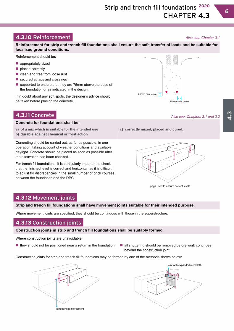
4.3
Strip and trench fill foundations 2020
CHAPTER 4.3 66
4.3.10 Reinforcement Also see: Chapter 3.1
Reinforcement for strip and trench fill foundations shall ensure the safe transfer of loads and be suitable for localised ground conditions.
Reinforcement should be:
�� appropriately sized �� placed correctly�� clean and free from loose rust�� secured at laps and crossings�� supported to ensure that they are 75mm above the base of the foundation or as indicated in the design.
If in doubt about any soft spots, the designer’s advice should be taken before placing the concrete.
75mm min. cover
75mm side cover
4.3.11 Concrete Also see: Chapters 3.1 and 3.2
Concrete for foundations shall be:a) of a mix which is suitable for the intended use b) durable against chemical or frost action
c) correctly mixed, placed and cured.
Concreting should be carried out, as far as possible, in one operation, taking account of weather conditions and available daylight. Concrete should be placed as soon as possible after the excavation has been checked.
For trench fill foundations, it is particularly important to check that the finished level is correct and horizontal, as it is difficult to adjust for discrepancies in the small number of brick courses between the foundation and the DPC.
pegs used to ensure correct levels
4.3.12 Movement jointsStrip and trench fill foundations shall have movement joints suitable for their intended purpose.
Where movement joints are specified, they should be continuous with those in the superstructure.
4.3.13 Construction jointsConstruction joints in strip and trench fill foundations shall be suitably formed.
Where construction joints are unavoidable:
�� they should not be positioned near a return in the foundation �� all shuttering should be removed before work continues beyond the construction joint.
Construction joints for strip and trench fill foundations may be formed by one of the methods shown below:
joint using reinforcement
joint with expanded metal lath

4.4.1 Compliance 014.4.2 Provisionofinformation 014.4.3 Siteconditions 014.4.4 Hazardousground 024.4.5 Servicesanddrainage 024.4.6 Safetransmissionofloads 034.4.7 Construction 034.4.8 Engineerchecks 054.4.9 Compressiblematerials 054.4.10 Reinforcement 054.4.11 Concrete 054.4.12 Movementjoints 054.4.13 Resistancetomoisture 06
This chapter gives guidance on meeting the Technical Requirements for raft, pile, pier and beam foundations.
Raft, pile, pier and beam foundations
CHAPTER 4.4
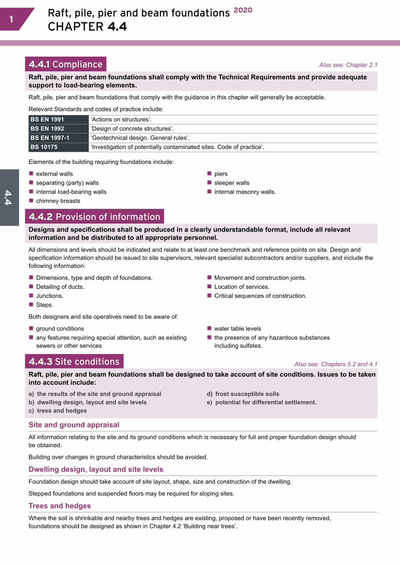
4.4
1 Raft, pile, pier and beam foundations 2020
CHAPTER 4.4 1
4.4.1 Compliance Also see: Chapter 2.1
Raft, pile, pier and beam foundations shall comply with the Technical Requirements and provide adequate support to load-bearing elements.
Raft, pile, pier and beam foundations that comply with the guidance in this chapter will generally be acceptable.
Relevant Standards and codes of practice include:
BS EN 1991 ‘Actions on structures’.BS EN 1992 ‘Design of concrete structures’.BS EN 1997-1 ‘Geotechnical design. General rules’. BS 10175 ‘Investigation of potentially contaminated sites. Code of practice’.
Elements of the building requiring foundations include:
�� external walls �� separating (party) walls �� internal load-bearing walls�� chimney breasts
�� piers�� sleeper walls�� internal masonry walls.
4.4.2 Provision of informationDesigns and specifications shall be produced in a clearly understandable format, include all relevant information and be distributed to all appropriate personnel.
All dimensions and levels should be indicated and relate to at least one benchmark and reference points on site. Design and specification information should be issued to site supervisors, relevant specialist subcontractors and/or suppliers, and include the following information:
�� Dimensions, type and depth of foundations.�� Detailing of ducts.�� Junctions.�� Steps.
�� Movement and construction joints.�� Location of services.�� Critical sequences of construction.
Both designers and site operatives need to be aware of:
�� ground conditions �� any features requiring special attention, such as existing sewers or other services
�� water table levels �� the presence of any hazardous substances including sulfates.
4.4.3 Site conditions Also see: Chapters 5.2 and 4.1
Raft, pile, pier and beam foundations shall be designed to take account of site conditions. Issues to be taken into account include:a) the results of the site and ground appraisalb) dwelling design, layout and site levelsc) trees and hedges
d) frost susceptible soilse) potential for differential settlement.
Site and ground appraisalAll information relating to the site and its ground conditions which is necessary for full and proper foundation design should be obtained.
Building over changes in ground characteristics should be avoided.
Dwelling design, layout and site levelsFoundation design should take account of site layout, shape, size and construction of the dwelling.
Stepped foundations and suspended floors may be required for sloping sites.
Trees and hedgesWhere the soil is shrinkable and nearby trees and hedges are existing, proposed or have been recently removed, foundations should be designed as shown in Chapter 4.2 ‘Building near trees’.
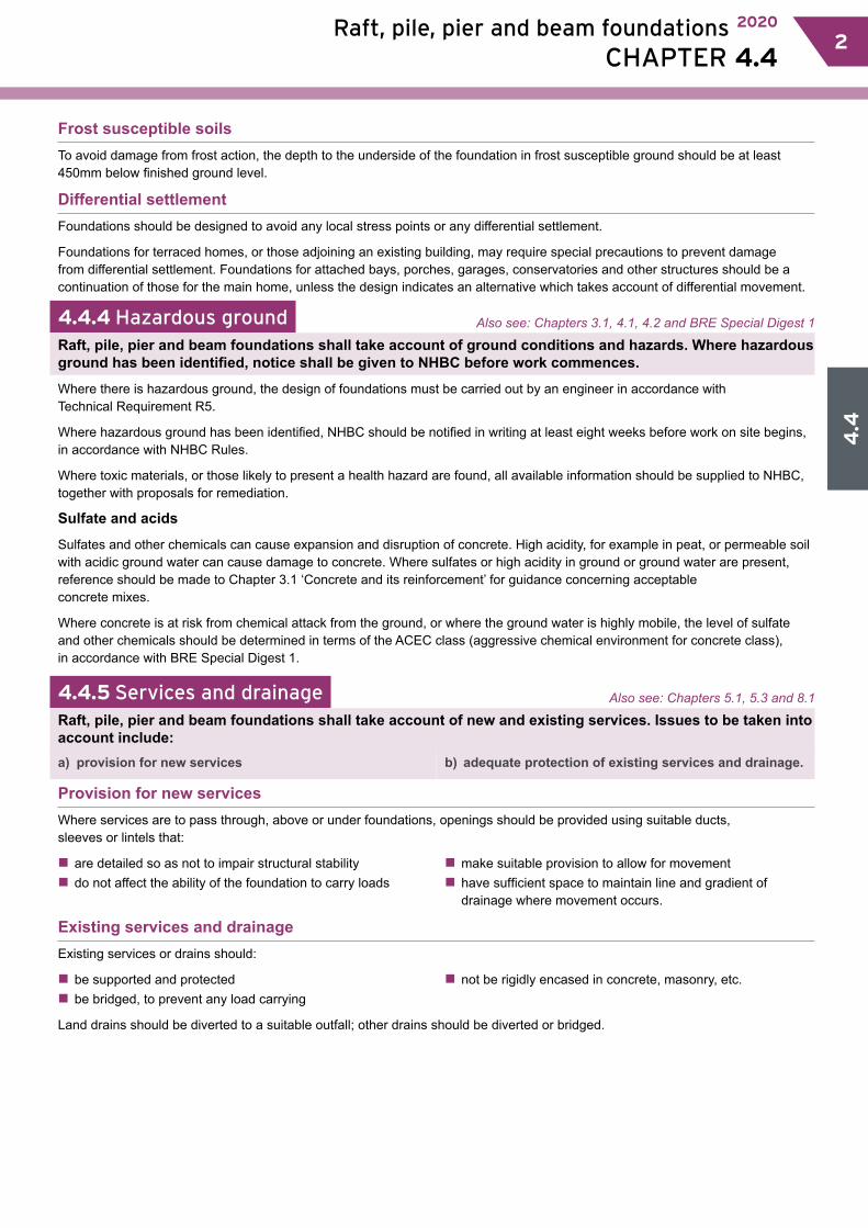
4.4
Raft, pile, pier and beam foundations 2020
CHAPTER 4.4 22
Frost susceptible soilsTo avoid damage from frost action, the depth to the underside of the foundation in frost susceptible ground should be at least 450mm below finished ground level.
Differential settlement Foundations should be designed to avoid any local stress points or any differential settlement.
Foundations for terraced homes, or those adjoining an existing building, may require special precautions to prevent damage from differential settlement. Foundations for attached bays, porches, garages, conservatories and other structures should be a continuation of those for the main home, unless the design indicates an alternative which takes account of differential movement.
4.4.4 Hazardous ground Also see: Chapters 3.1, 4.1, 4.2 and BRE Special Digest 1
Raft, pile, pier and beam foundations shall take account of ground conditions and hazards. Where hazardous ground has been identified, notice shall be given to NHBC before work commences.
Where there is hazardous ground, the design of foundations must be carried out by an engineer in accordance with Technical Requirement R5.
Where hazardous ground has been identified, NHBC should be notified in writing at least eight weeks before work on site begins, in accordance with NHBC Rules.
Where toxic materials, or those likely to present a health hazard are found, all available information should be supplied to NHBC, together with proposals for remediation.
Sulfate and acids
Sulfates and other chemicals can cause expansion and disruption of concrete. High acidity, for example in peat, or permeable soil with acidic ground water can cause damage to concrete. Where sulfates or high acidity in ground or ground water are present, reference should be made to Chapter 3.1 ‘Concrete and its reinforcement’ for guidance concerning acceptable concrete mixes.
Where concrete is at risk from chemical attack from the ground, or where the ground water is highly mobile, the level of sulfate and other chemicals should be determined in terms of the ACEC class (aggressive chemical environment for concrete class), in accordance with BRE Special Digest 1.
4.4.5 Services and drainage Also see: Chapters 5.1, 5.3 and 8.1
Raft, pile, pier and beam foundations shall take account of new and existing services. Issues to be taken into account include:a) provision for new services b) adequate protection of existing services and drainage.
Provision for new servicesWhere services are to pass through, above or under foundations, openings should be provided using suitable ducts, sleeves or lintels that:
�� are detailed so as not to impair structural stability�� do not affect the ability of the foundation to carry loads
�� make suitable provision to allow for movement�� have sufficient space to maintain line and gradient of drainage where movement occurs.
Existing services and drainageExisting services or drains should:
�� be supported and protected�� be bridged, to prevent any load carrying
�� not be rigidly encased in concrete, masonry, etc.
Land drains should be diverted to a suitable outfall; other drains should be diverted or bridged.
4.4
3 Raft, pile, pier and beam foundations 2020
CHAPTER 4.4 3
4.4.6 Safe transmission of loads Also see: Chapter 5.1
Raft, pile, pier and beam foundations shall be designed to transmit loads from the structure to the ground safely, without excessive settlement.
Raft, pile, pier and beam foundations should safely transmit loads. The following issues should be taken into account:
�� adequate stiffness to ensure that differential movement does not adversely affect the supported structure�� nature and bearing capacity of the fill material to be placed under the foundation
�� specification of concrete and cover to reinforcement.
Raft and semi-raft foundations:Raft and semi-raft foundations should be designed:
�� to prevent the erosion of ground beneath the raft�� (where required) to accommodate warm air ducts, service ducts or services without any adverse effect upon the performance of the foundation
�� to limit the risk of ducts becoming flooded.
Fill for raft foundations should be in accordance with Chapter 5.1 ‘Substructure and ground-bearing floors’.
Semi-raft foundations on made ground:The following notes are to be used as a guide for engineers designing raft foundations, but are by no means exhaustive. Special consideration will be required for certain sites.
�� Raft foundations are to be designed by a chartered civil or structural engineer taking account of ground conditions and the results of the site appraisal and ground assessment.�� Sufficient internal beams are to be provided to stiffen the slab adequately.�� The area between downstand beams should not be greater than 35m2.�� The ratio of adjacent sides on plan should not exceed 2:1.�� The minimum depth of perimeter and party wall beams is to be 450mm. On larger homes, some internal beams should be of the same depth as the perimeter beams.�� Perimeter and internal beams should be sufficiently wide at their base to carry their total loading at the allowable bearing pressure for the site.�� Beams are to be designed to span 3m simply supported and cantilever 1.5m.
�� Beams are to use properly formed reinforcement in accordance with BS EN 1992-1-1.�� Where mesh is used in beams, it should be delivered to the site pre-bent.�� All beams should be cast on a minimum of 50mm concrete blinding.�� Minimum cover to reinforcement should be 40mm.�� Floor slabs should be a minimum 150mm thick, with nominal top face reinforcement as a minimum and anti-crack reinforcement in the bottom face, where appropriate.�� Stools or similar should be used to support floor slab mesh during casting.�� Corners and junctions to beams should be adequately tied using similar reinforcement to the beams.�� A minimum cavity drain of 225mm below the DPC is to be maintained.
Piled foundations:The design of all piled foundations should specify precautions for cohesive soils where volume changes can occur.
The bearing capacity and integrity of piles should be confirmed by testing, when required.
4.4.7 ConstructionRaft, pile, pier and beam foundations shall be constructed in accordance with the design. Issues to be taken into account include:a) setting out and excavationsb) localised effects and trench bottoms
c) installation of piles, piers and ground beamsd) load capacity verification of piles.
Setting out and excavationsThe accuracy of setting out should be checked by control measurements of trenches, including their location relative to site boundaries and adjacent buildings. Levels should be checked against benchmarks, where appropriate. For excavations, check:
�� trench lengths �� trench widths
�� length of diagonals between external corners.
Also see: Chapter 4.2
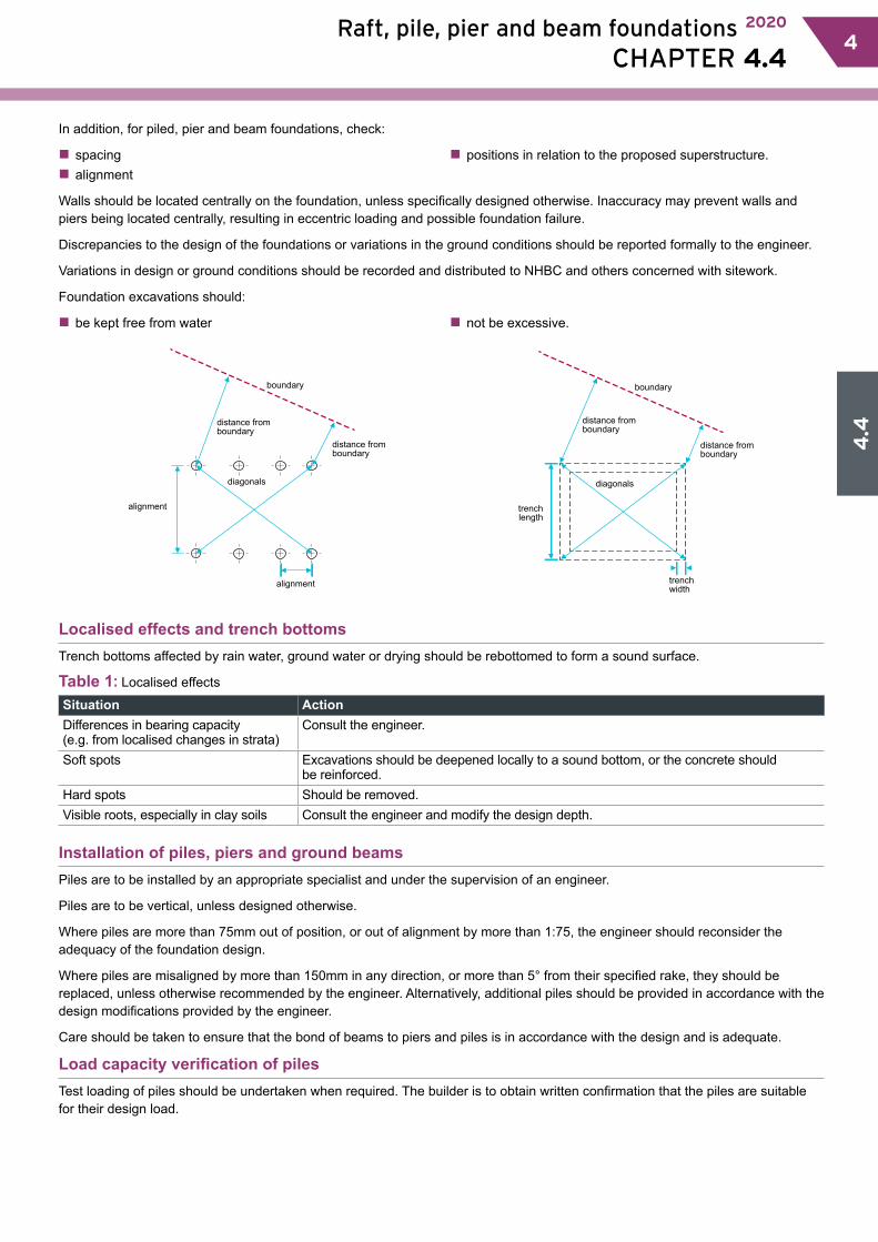
4.4
Raft, pile, pier and beam foundations 2020
CHAPTER 4.4 44
In addition, for piled, pier and beam foundations, check:
�� spacing �� alignment
�� positions in relation to the proposed superstructure.
Walls should be located centrally on the foundation, unless specifically designed otherwise. Inaccuracy may prevent walls and piers being located centrally, resulting in eccentric loading and possible foundation failure.
Discrepancies to the design of the foundations or variations in the ground conditions should be reported formally to the engineer.
Variations in design or ground conditions should be recorded and distributed to NHBC and others concerned with sitework.
Foundation excavations should:
�� be kept free from water �� not be excessive.
alignment
distance fromboundary
distance fromboundary
alignment
boundary
diagonals
trenchlength
distance fromboundary
distance fromboundary
trenchwidth
boundary
diagonals
Localised effects and trench bottomsTrench bottoms affected by rain water, ground water or drying should be rebottomed to form a sound surface.
Table 1: Localised effects
Situation ActionDifferences in bearing capacity (e.g. from localised changes in strata)
Consult the engineer.
Soft spots Excavations should be deepened locally to a sound bottom, or the concrete should be reinforced.
Hard spots Should be removed.Visible roots, especially in clay soils Consult the engineer and modify the design depth.
Installation of piles, piers and ground beamsPiles are to be installed by an appropriate specialist and under the supervision of an engineer.
Piles are to be vertical, unless designed otherwise.
Where piles are more than 75mm out of position, or out of alignment by more than 1:75, the engineer should reconsider the adequacy of the foundation design.
Where piles are misaligned by more than 150mm in any direction, or more than 5° from their specified rake, they should be replaced, unless otherwise recommended by the engineer. Alternatively, additional piles should be provided in accordance with the design modifications provided by the engineer.
Care should be taken to ensure that the bond of beams to piers and piles is in accordance with the design and is adequate.
Load capacity verification of pilesTest loading of piles should be undertaken when required. The builder is to obtain written confirmation that the piles are suitable for their design load.
4.4
5 Raft, pile, pier and beam foundations 2020
CHAPTER 4.4 5
4.4.8 Engineer checksEngineer-designed foundations shall be inspected by the engineer during construction.
The engineer should undertake site visits to ensure that the design of the foundation is suitable for the actual ground conditions encountered, and that the construction is in accordance with the design.
4.4.9 Compressible materials Also see: Chapter 4.2
Compressible materials shall be capable of absorbing potential heave forces
Materials used to accommodate heave should be assessed in accordance with Technical Requirement R3 and used in accordance with the manufacturer’s recommendations and independent assessment when applicable.
4.4.10 ReinforcementReinforcement of raft, pile, pier and beam foundations shall be in accordance with the design, sufficient to ensure the safe transfer of loads and be suitable for localised ground conditions.
Reinforcement should be:
�� appropriately sized�� placed correctly�� clean and free from loose rust
�� secured at laps and crossings�� properly supported to ensure that the cover indicated in the design is maintained.
Reinforcement may be necessary, for example at construction joints or over small localised soft spots or changes in bearing strata.
4.4.11 ConcreteConcrete for raft, pile, pier and beam foundations shall be:a) of a suitable mix design to achieve the required
strength and resistance to chemical and frost action b) correctly mixed, placed and cured.
Mixing, placing, testing and curing of concrete should be carried out as indicated in Chapter 3.1 ‘Concrete and its reinforcement’ and when work is carried out in cold weather, Chapter 3.2 ‘Cold weather working’.
Suitable mixConcrete should be of a mix which:
�� will achieve the required strength and not impair the performance of the foundation
�� is sufficiently resistant to chemical and frost action.
Correctly mixed, placed and curedBefore concrete is placed, excavations and reinforcement may need to be approved by the engineer or their representative and, in England and Wales, foundations should be approved by the person responsible for building control inspections.
Concreting should:
�� be carried out in one operation (as far as possible)�� take account of weather conditions and available daylight
�� be placed as soon as possible after the excavation or after the reinforcement has been checked �� be placed in even, compact and reasonably dry trenches.
4.4.12 Movement jointsRaft, pile, pier and beam foundations shall have movement joints suitable for their intended purpose, and be formed using appropriate materials.
Movement joints should be located so as to limit the risk of damage caused by movement. The design of movement joints and choice of sealing materials should consider:
�� anticipated movement�� movement capability of seal �� designed joint width �� actual joint width
�� joint depth �� surface preparation �� backing medium �� projected life span of the joint.
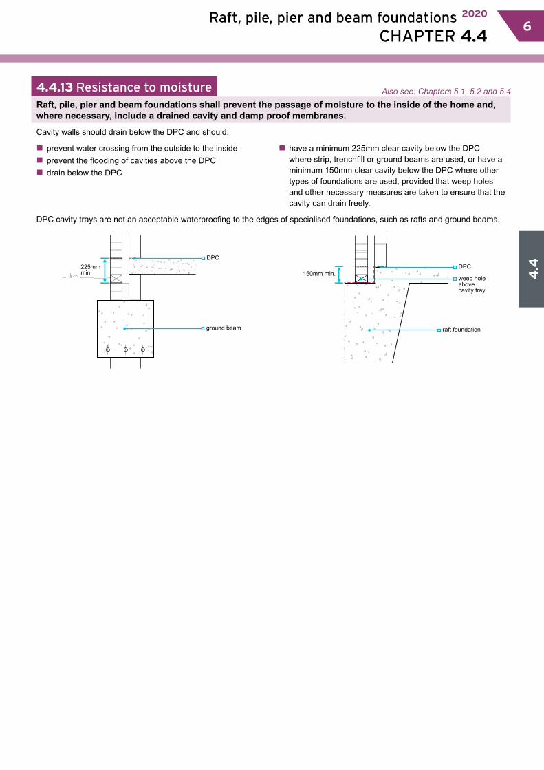
4.4
Raft, pile, pier and beam foundations 2020
CHAPTER 4.4 66
4.4.13 Resistance to moistureRaft, pile, pier and beam foundations shall prevent the passage of moisture to the inside of the home and, where necessary, include a drained cavity and damp proof membranes.
Cavity walls should drain below the DPC and should:
�� prevent water crossing from the outside to the inside�� prevent the flooding of cavities above the DPC�� drain below the DPC
�� have a minimum 225mm clear cavity below the DPC where strip, trenchfill or ground beams are used, or have a minimum 150mm clear cavity below the DPC where other types of foundations are used, provided that weep holes and other necessary measures are taken to ensure that the cavity can drain freely.
DPC cavity trays are not an acceptable waterproofing to the edges of specialised foundations, such as rafts and ground beams.
225mmmin.
DPC
ground beam
150mm min.DPC
raft foundation
weep holeabove cavity tray
Also see: Chapters 5.1, 5.2 and 5.4

4.5.1 Compliance 014.5.2 Hazardoussitesandgroundhazards 014.5.3 Deskstudyandsiteinvestigation 014.5.4 Confirmationofsuitability fortreatment 024.5.5 Suitabilityofgroundconditions 024.5.6 Compatibilityoftheground, designandtreatment 054.5.7 Acceptablemethods 064.5.8 Materialsforuseasfill 074.5.9 Granularmaterial 084.5.10 Sitework 084.5.11 Adjacentexcavations 094.5.12 Verificationofcompletedtreatment 09
This chapter gives guidance on meeting the Technical Requirements and recommendations for vibratory ground improvement techniques.
Vibratory ground improvement techniques
CHAPTER 4.5

4.5
1 Vibratory ground improvement techniques 2020
CHAPTER 4.5 1
Introduction
The vibratory process is generally applied to weak natural soils and filled ground. The purpose is to improve the load-bearing capacity, reduce settlement and provide an adequate bearing stratum for the foundation supporting the home.
4.5.1 Compliance Also see: Chapter 2.1
Vibratory ground improvement techniques shall comply with the Technical Requirements and be designed by an engineer in accordance with established standards and codes of practice.
Vibratory ground improvement techniques that comply with the guidance in this chapter, and that are in accordance with the relevant British Standards, building regulations and statutory requirements, will generally be acceptable.
Design of vibratory ground improvement, including foundations, should be carried out by an engineer experienced in ground improvement techniques in accordance with Technical Requirement R5. In this chapter, the term ‘engineer’ refers to an appropriate engineer who is independent of the contractor responsible for the vibratory ground improvement techniques.
British Standards, codes of practice and authoritative documents relevant to vibratory ground improvement techniques and site investigations include:
BS 10175 ‘Investigation of potentially contaminated sites – Code of practice’.BS EN 1991 ‘Actions on structures’.BS EN 1997-1 ‘General rules’.BS EN 1997-2 ‘Ground investigation and testing’BS EN 14731 ‘Execution of special geotechnical works – Ground treatment by deep vibration’. BS EN ISO 14688 ‘Geotechnical investigation and testing – Identification and classification of soil’. BS EN ISO 14689 ‘Geotechnical investigation and testing – Identification and classification of rock’.BS EN ISO 22476 ‘Geotechnical investigation and testing – Field testing’. BR 391 ‘Specifying vibro stone columns’.ICE ‘Specification for Ground Treatment’.
4.5.2 Hazardous sites and ground hazards Also see: Chapter 2.1, 4.1 and 4.2
Vibratory ground improvement techniques on hazardous sites shall be reported to NHBC before work on site commences, and be designed to take account of the characteristics of the site, including any ground hazards.
Hazardous sites, as defined in the NHBC Rules, should be reported to NHBC in writing at least eight weeks before sitework begins.
Details of ground hazards to be taken into consideration are given in Chapter 4.1 ‘Land quality – managing ground conditions’ and Chapter 4.2 ‘Building near trees’.
4.5.3 Desk study and site investigationThe engineer shall ensure a desk study and site investigation are undertaken and findings used to inform the design.
The engineer should establish the scope of, and supervise, the site investigation, taking account of the findings of the desk study, and relevant standards listed in Clause 4.5.1.
The specialist contractor should be satisfied that the site investigation provides adequate and representative information in order to design the ground improvements. The results of the site investigation and desk study should be sent to NHBC prior to work starting and should, as a minimum, determine the items listed in Table 1.
Also see: Chapter 2.1, 4.1 and 4.2
4.5
Vibratory ground improvement techniques 2020
CHAPTER 4.5 22
Table 1: Results of the site investigation and desk study
Item to be determined GuidanceDepths and properties of natural materials under the site
Includes the presence of caves, workings, or natural phenomena such as rocks or soils which dissolve or erode when exposed to the passage of water. Data for comparison with post-treatment properties should be established.
Extent and nature of any areas of filled ground on the site
Includes:�� proportions and distribution of constituent materials�� state of compaction of the fill material throughout its depth�� grading and particle size distribution of fill materials�� potential for gas generation from fill materials�� potential for spontaneous combustion of fill and/or natural deposits.
Presence and extent of any existing or redundant services and drains
Includes information on the extent and nature of the backfill to the excavations.
The effect of sustainable drainage systems
Includes the effect that any sustainable drainage system (SuDS) may have on the geotechnical parameters of the site.
Presence, level and nature of any ground water
Includes the potential for ground water to rise and cause heave or collapse by saturation.
Previous structures Includes any potential underground obstructions or hard-spots, e.g. basement walls, floor slabs, which remain.
Occurrence of contaminated substances
Includes the presence and extent of contaminated substances or gases present or suspected.
4.5.4 Confirmation of suitability for treatmentThe builder shall obtain written confirmation from the engineer and specialist contractor that the site is suitable for the proposed ground improvement system.
NHBC should be notified prior to work starting, that the site is suitable for the proposed system. The engineer and specialist contractor should agree the following in writing before work commences on site:
�� Design objectives. �� Detailed schedule of work.�� Programme of work.
�� Tests to be conducted on completion of the work. �� Responsibility for procedures and tests.
The following considerations should be taken into account:
�� Layout and depth of the stone columns and the accuracy to be achieved.�� Safety issues to be incorporated into the design to allow for unforeseen circumstances. �� Criteria for non-acceptance of the vibrating poker worktests to be conducted on completion of the work.
�� Responsibility for procedures and tests. �� Calculations and case histories required to justify the ground improvement proposals together with the layout of the stone columns and details of the equipment and process to be used on site.
These written agreements should be made available to NHBC before work commences on site.
4.5.5 Suitability of ground conditions Also see: Chapter 2.1, 4.1 and 4.2
Vibratory ground improvement techniques shall only be conducted on suitable ground and be appropriate for the site conditions. Issues to be taken into account include:a) unsuitable ground conditionsb) detrimental factors
c) ground water conditions.
The engineer should assess the ground and be satisfied that it is suitable for treatment. Conditions acceptable for treatment are only those within zones A and B of Chart 1.
Also see: Chapter 2.1, 4.1 and 4.2
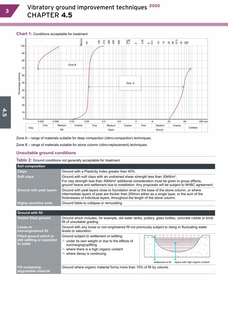
4.5
3 Vibratory ground improvement techniques 2020
CHAPTER 4.5 3
Chart 1: Conditions acceptable for treatment
Pe
rce
nta
ge
pa
ssin
g
100
90
80
70
60
50
40
30
20
10
0
ClayFine Medium
Silt
Coarse Fine Medium
Sand
Coarse Fine Medium
GravelCobbles
Coarse
0.006 0.02 0.06 0.2 0.6 2 6 20 60 200 mm0.002
Mic
ron
36
51
0 21
2
00
3
52
4
00
6
mm
81.
1 2
3.3
5
5
3.6
01
41
02
82
73
5.
50 3
65
7
Zone A
Zone B
Zone A – range of materials suitable for deep compaction (vibro-compaction) techniques.
Zone B – range of materials suitable for stone column (vibro-replacement) techniques.
Unsuitable ground conditionsTable 2: Ground conditions not generally acceptable for treatment
Soil compositionClays Ground with a Plasticity Index greater than 40%.Soft clays Ground with soft clays with an undrained shear strength less than 30kN/m2.
For clay strength less than 30kN/m2 additional consideration must be given to group effects, ground heave and settlement due to installation. Any proposals will be subject to NHBC agreement.
Ground with peat layers Ground with peat layers close to foundation level or the base of the stone column, or where intermediate layers of peat are thicker than 200mm either as a single layer, or the sum of the thicknesses of individual layers, throughout the length of the stone column.
Highly sensitive soils Ground liable to collapse or remoulding.
Ground with fillVoided filled ground Ground which includes, for example, old water tanks, pottery, glass bottles, concrete rubble or brick
fill of unsuitable grading.Loose or non-engineered fill
Ground with any loose or non-engineered fill not previously subject to rising or fluctuating water levels or saturation.
Filled ground which is still settling or expected to settle
Ground subject to settlement or settling:�� under its own weight or due to the effects of surcharging/upfilling �� where there is a high organic content �� where decay is continuing.
settlement of fill layers with high organic content
Fill containing degradable material
Ground where organic material forms more than 15% of fill by volume.

4.5
Vibratory ground improvement techniques 2020
CHAPTER 4.5 44
Highly contaminated groundGround which includes, for example toxic waste, or where inflammable, explosive or toxic gas generation may take place
Stone columns may act as vertical vents. Consideration will be given to proprietary systems which do not permit vertical venting such as vibro concrete plug technology.
stone column acting as vent for dangerous gases
Detrimental factorsWhen specifying vibratory ground improvement techniques, the following factors should be considered:
�� Partial depth treatment of filled ground. The engineer should be satisfied with the anticipated performance of both the treated and untreated zones. �� The specialist contractor should take responsibility for the treated zone and the depth of treatment.�� Alterations to the oversite level before or after treatment, or the disturbance of ground by excavations after treatment.�� Soils with a Modified Plasticity Index of 10% or greater; foundations should be designed to accommodate volume changes.
�� Obstructions and variations in the density of fill and natural ground (hard spots) and the location of changes in the profile of the natural underlying ground, e.g. edges of pits or quarries, slopes, or manmade obstructions such as soakaways or drainage runs.�� The minimum depth of soil treated, which should allow for the interaction of adjacent foundations. �� Stone columns that may form vertical drains, allowing the passage of water to a moisture-susceptible strata, or provide seepage paths for gases.
foundation depth in accordance with Chapter 4.2
house A house B
interaction of adjacent foundations
stone column actingas soakaway
Ground water conditions�� Long-term lowering of the water table causing settlement of existing adjacent buildings.
�� Short-term rise in local water table due to large volumes of water used in wet process during construction causing settlement or heave of existing adjacent buildings.
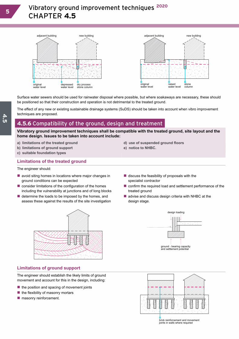
4.5
5 Vibratory ground improvement techniques 2020
CHAPTER 4.5 5
dry processstone column
depressed water level
originalwater level
adjacent building new building
stone column
raisedwater level
originalwater level
adjacent building new building
Surface water sewers should be used for rainwater disposal where possible, but where soakaways are necessary, these should be positioned so that their construction and operation is not detrimental to the treated ground.
The effect of any new or existing sustainable drainage systems (SuDS) should be taken into account when vibro improvement techniques are proposed.
4.5.6 Compatibility of the ground, design and treatmentVibratory ground improvement techniques shall be compatible with the treated ground, site layout and the home design. Issues to be taken into account include:a) limitations of the treated groundb) limitations of ground support c) suitable foundation types
d) use of suspended ground floorse) notice to NHBC.
Limitations of the treated groundThe engineer should:
�� avoid siting homes in locations where major changes in ground conditions can be expected�� consider limitations of the configuration of the homes including the vulnerability at junctions and of long blocks�� determine the loads to be imposed by the homes, and assess these against the results of the site investigation
�� discuss the feasibility of proposals with the specialist contractor�� confirm the required load and settlement performance of the treated ground�� advise and discuss design criteria with NHBC at the design stage.
ground - bearing capacity and settlement potential
design loading
Limitations of ground supportThe engineer should establish the likely limits of ground movement and account for this in the design, including:
�� the position and spacing of movement joints�� the flexibility of masonry mortars�� masonry reinforcement.
brick reinforcement and movementjoints in walls where required
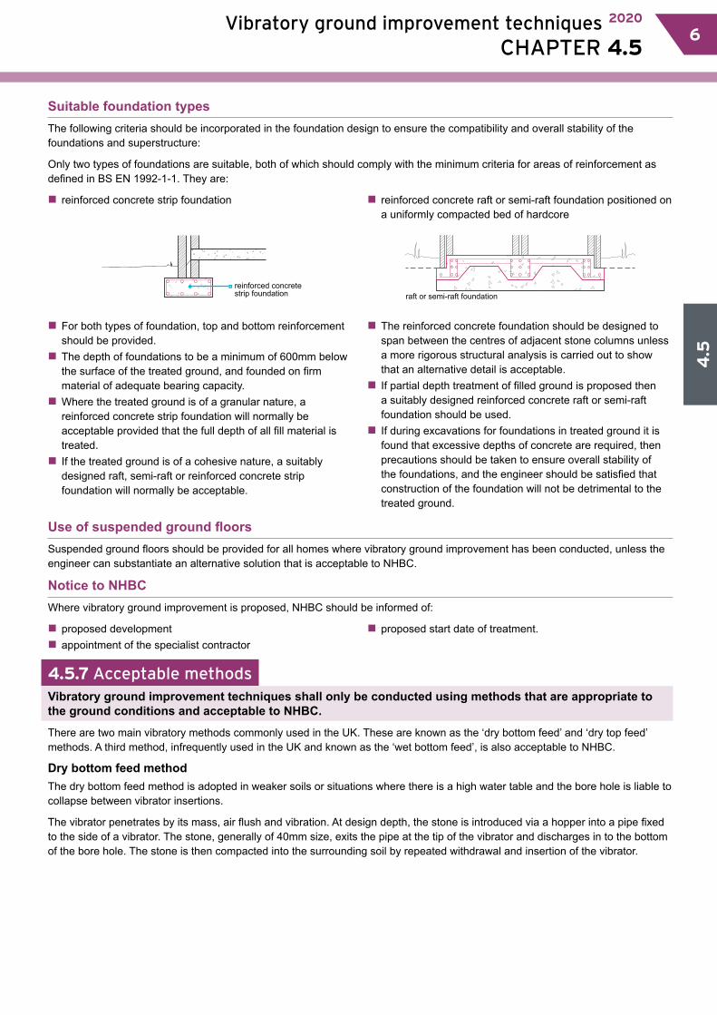
4.5
Vibratory ground improvement techniques 2020
CHAPTER 4.5 66
Suitable foundation typesThe following criteria should be incorporated in the foundation design to ensure the compatibility and overall stability of the foundations and superstructure:
Only two types of foundations are suitable, both of which should comply with the minimum criteria for areas of reinforcement as defined in BS EN 1992-1-1. They are:
�� reinforced concrete strip foundation �� reinforced concrete raft or semi-raft foundation positioned on a uniformly compacted bed of hardcore
reinforced concretestrip foundation raft or semi-raft foundation
�� For both types of foundation, top and bottom reinforcement should be provided.�� The depth of foundations to be a minimum of 600mm below the surface of the treated ground, and founded on firm material of adequate bearing capacity.�� Where the treated ground is of a granular nature, a reinforced concrete strip foundation will normally be acceptable provided that the full depth of all fill material is treated.�� If the treated ground is of a cohesive nature, a suitably designed raft, semi-raft or reinforced concrete strip foundation will normally be acceptable.
�� The reinforced concrete foundation should be designed to span between the centres of adjacent stone columns unless a more rigorous structural analysis is carried out to show that an alternative detail is acceptable.�� If partial depth treatment of filled ground is proposed then a suitably designed reinforced concrete raft or semi-raft foundation should be used.�� If during excavations for foundations in treated ground it is found that excessive depths of concrete are required, then precautions should be taken to ensure overall stability of the foundations, and the engineer should be satisfied that construction of the foundation will not be detrimental to the treated ground.
Use of suspended ground floorsSuspended ground floors should be provided for all homes where vibratory ground improvement has been conducted, unless the engineer can substantiate an alternative solution that is acceptable to NHBC.
Notice to NHBCWhere vibratory ground improvement is proposed, NHBC should be informed of:
�� proposed development�� appointment of the specialist contractor
�� proposed start date of treatment.
4.5.7 Acceptable methodsVibratory ground improvement techniques shall only be conducted using methods that are appropriate to the ground conditions and acceptable to NHBC.
There are two main vibratory methods commonly used in the UK. These are known as the ‘dry bottom feed’ and ‘dry top feed’ methods. A third method, infrequently used in the UK and known as the ‘wet bottom feed’, is also acceptable to NHBC.
Dry bottom feed methodThe dry bottom feed method is adopted in weaker soils or situations where there is a high water table and the bore hole is liable to collapse between vibrator insertions.
The vibrator penetrates by its mass, air flush and vibration. At design depth, the stone is introduced via a hopper into a pipe fixed to the side of a vibrator. The stone, generally of 40mm size, exits the pipe at the tip of the vibrator and discharges in to the bottom of the bore hole. The stone is then compacted into the surrounding soil by repeated withdrawal and insertion of the vibrator.
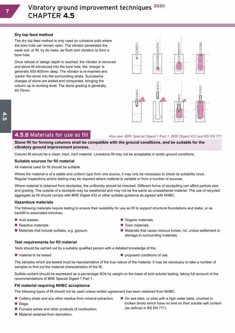
4.5
7 Vibratory ground improvement techniques 2020
CHAPTER 4.5 7
Dry top feed method The dry top feed method is only used on cohesive soils where the bore hole can remain open. The vibrator penetrates the weak soil, or fill, by its mass, air flush and vibration to form a bore hole.
Once refusal or design depth is reached, the vibrator is removed and stone fill introduced into the bore hole, the ‘charge’ is generally 500-800mm deep. The vibrator is re-inserted and ‘packs’ the stone into the surrounding strata. Successive charges of stone are added and compacted, bringing the column up to working level. The stone grading is generally 40-75mm.
4.5.8 Materials for use as fill Also see: BRE Special Digest 1 Part 1, BRE Digest 433 and BS EN 771
Stone fill for forming columns shall be compatible with the ground conditions, and be suitable for the vibratory ground improvement process.
Column fill should be a clean, hard, inert material. Limestone fill may not be acceptable in acidic ground conditions.
Suitable sources for fill material All material used for fill should be suitable.
Where the material is of a stable and uniform type from one source, it may only be necessary to check its suitability once. Regular inspections and/or testing may be required where material is variable or from a number of sources.
Where material is obtained from stockpiles, the uniformity should be checked. Different forms of stockpiling can affect particle size and grading. The outside of a stockpile may be weathered and may not be the same as unweathered material. The use of recycled aggregate as fill should comply with BRE Digest 433 or other suitable guidance as agreed with NHBC.
Hazardous materialsThe following materials require testing to ensure their suitability for use as fill to support structural foundations and slabs, or as backfill to associated trenches:
�� Acid wastes. �� Reactive materials. �� Materials that include sulfates, e.g. gypsum.
�� Organic materials. �� Toxic materials. �� Materials that cause noxious fumes, rot, undue settlement or damage to surrounding materials.
Test requirements for fill materialTests should be carried out by a suitably qualified person with a detailed knowledge of the:
�� material to be tested �� proposed conditions of use.
The samples which are tested must be representative of the true nature of the material. It may be necessary to take a number of samples to find out the material characteristics of the fill.
Sulfate content should be expressed as a percentage SO4 by weight on the basis of acid soluble testing, taking full account of the recommendations of BRE Special Digest 1 Part 1.
Fill material requiring NHBC acceptance The following types of fill should not be used unless written agreement has been obtained from NHBC:
�� Colliery shale and any other residue from mineral extraction.�� Slags. �� Furnace ashes and other products of combustion.�� Material obtained from demolition.
�� On wet sites, or sites with a high water table, crushed or broken bricks which have no limit on their soluble salt content (as defined in BS EN 771).

4.5
Vibratory ground improvement techniques 2020
CHAPTER 4.5 88
Expansive fill materialsFill containing expansive material is not acceptable for use as support to structural foundations and slabs, or as backfill to associated trenches.
4.5.9 Granular materialGranular material for raising site levels before treatment, or adding during deep compaction, shall be suitable for compaction and, unless appropriate precautions are taken, be free from hazardous materials.
The grading of material for adding during deep compaction should be within Zone A of Chart 1. Well graded, inert fill which passes a 100mm x 100mm screen in all directions and contains less than 10% fine material of silt or clay size will generally be acceptable for raising site levels.
Precautions, including testing where appropriate, should be taken where hazardous materials are present in fill.
4.5.10 SiteworkWhen using vibratory ground improvement techniques, the builder shall ensure that the engineer visits the site and provides competent supervision throughout the ground treatment process. Issues to be taken into account include:a) engineer checksb) location, depth and alignment of columns
c) managing unforeseen circumstances.
Engineer checksThe engineer should provide competent site supervision throughout the ground treatment process and at critical stages, including:
�� the inspection of setting out �� the installation of columns during the early stage of the work�� checking of materials
�� where installation data differs from design assumptions �� where changes in treatment layout are required.
Some aspects of sitework may be the responsibility of the engineer or their representative, or of the specialist contractor, rather than of the builder.
Location, depth and alignment of columnsSupervision should ensure that:
�� the minimum required depth of the stone columns is achieved and each one correctly located (the builder should provide sufficient profiles to enable locations tobe checked) �� the stone columns are located either centrally under the foundations they are to support or are in the predetermined staggered arrangement, at a maximum of 2m centres and at the intersection of adjacent reinforced concrete strips
�� missing stone columns are replaced �� stone columns which are misaligned by more than 150mm in any direction are replaced �� the location of all stone columns is checked by the engineer’s representative prior to the specialist plant leaving the site.
2m max. centres
2m max. centres
missing stonecolumn =new column required
stone columnmisaligned bymore than150mm =new column requiredin correct position
stone column misaligned by less than150mm =no action needed

4.5
9 Vibratory ground improvement techniques 2020
CHAPTER 4.5 9
Managing unforeseen circumstances
Table 3: Actions for managing unforeseen circumstances
Circumstance Action In all casesUnforeseen changes or trends which affect the site conditions
Recorded and reported to the engineer immediately
Where there is an effect on the final efficiency of the treatment, this should be fully considered by the engineer and the specialist contractor. The builder and NHBC are to be advised immediately regarding proposed remedial measures.
Change in the anticipated depth of the compaction point in excess of 25%
Recorded and reported to the engineer and specialist contractor as soon as possible but no later than the end of the working day of occurrence
Variation of over 50% in the quantity of backfill used in compaction points of the same length
depth 25%greater thananticipated
50% morebackfill thananticipated
Allowance should be made for unforeseen obstructions that require either local removal and backfilling prior to treatment, realignment or additional columns, coupled with local amendment of foundation design.
4.5.11 Adjacent excavationsThe builder shall ensure that foundations are not disturbed by adjacent excavations.
The engineer should consider the influence of drainage and other service trenches on the stability of the complete design.
The minimum clearance between excavations and foundations must not be less than the depth of excavation minus the depth of the structural foundation. Particular attention is needed for excavation below the water table.
excavation anddrain/servicetrenches shouldbe above 45º line
4.5.12 Verification of completed treatmentThe engineer shall require the specialist contractor to verify that the ground treatment is satisfactory, including:a) suitable testingb) written confirmation of completed treatment
c) recording of work.
Suitable testing
Tests should be carried out to establish the degree of ground improvement, the load-bearing characteristics and settlement potential.
The specialist contractor should:
�� predict the results from his experience of work on the type of ground prior to the test taking place�� agree results and tolerance with the engineer prior to testing
�� agree results and tolerance with the engineer with actual results.
Where the results are vastly different, a further investigation may be necessary.
Where a threefold improvement were predicted and only a twofold improvement achieved, this could indicate that the ground was different to that identified in the investigation, or that the treatment carried out differed from the specified treatment.
Tests on ground containing clay soils may need to be conducted several days after completion to allow excess pore pressures to dissipate. The engineer may choose any appropriate combination of the tests detailed in Table 4, with the agreement of NHBC.

4.5
Vibratory ground improvement techniques 2020
CHAPTER 4.5 1010
Table 4: Test methods
Test Comments600mm diameter plate tests Plate tests will not determine the design but will allow for an assessment to be made of the
workmanship on the stone columns. The tests should be carried out on stone columns or treated ground at a frequency of at least one test per day per rig.
Dummy footing test/mini zone test
A mini zone test can be used as a limited substitute for zone tests. The test should be applied to at least two stone columns and the area of foundation which they support. The load may be applied through a rigid beam or stiffened plate using skips or other known loads, arranged to give a uniform distribution of the load.
Mini zone tests should be continued for a sufficient time to allow creep behaviour to be quantified. Allowances for this time should be made in the overall project programme.
Zone test An isolated pad or strip footing is used to test up to eight stone columns and the intervening ground. Loadings which should simulate the dwelling loads are held for 24 hours at predetermined stages to examine creep behaviour.
In-situ test Where vibration will improve the ground itself, e.g. granular materials, then in-situ testing is appropriate.Improvement can be assessed when the in-situ test results are compared with the pretreatment investigation.
Trial pits Trial pits can be excavated around trial stone columns to prove that they are fully formed and to the required depth and diameter. This is a destructive test, and allowance should be made accordingly.
Written confirmation of completed treatment
On completion of the treatment, the engineer should:
�� use the test results to verify that the treated ground has achieved the anticipated condition assumed in the design �� advise the builder and NHBC in writing of the verified effectiveness of treatment in relation to the design
�� advise the builder of any special precautions which should be taken for the positioning of services both beneath the home and adjacent to it.
Recording of work
A comprehensive record of all works should be made available to NHBC, including:
�� information concerning the treatment�� depth of fill�� volume of stone used
�� on-site changes�� any other relevant information.