Embed Size (px)
DESCRIPTION
SDMS
Citation preview

Saudi Electricity Company الشرآة السعودية للكهرباء
32-SDMS-02 SEC DISTRIBUTION MATERIALS SPECIFICATION DATE: 15-09-2004G
32-SDMS-02
SPECIFICATIONS
FOR
MV METERED RING MAIN UNIT UP TO 36 KV
This specification is property of SEC and subject to change or modification without any notice

Saudi Electricity Company الشرآة السعودية للكهرباء
32-SDMS-02 SEC DISTRIBUTION MATERIALS SPECIFICATION DATE: 15-09-2004G
Page 2 of 25
CONTENTS PAGE
1.0 SCOPE 3 2.0 CROSS REFERENCES 3 3.0 APPLICABLE CODES AND STANDARDS 3 4.0 DESIGN AND CONSTRUCTION REQUIREMENTS 4 4.1 General 4 4.2 Current rating 5 4.3 Ring switches 5 4.4 Circuit breaker 6 4.5 Protective relay 7 4.6 Operations 7 4.7 Cable testing facility 7 4.8 Interlocks 7 4.9 Terminations / cable compartments 8 4.10 Earthing 9 4.11 Voltage Indicator Lamps / Phase Comparators 9 4.12 Earth Fault Indicator (EFI) 9 4.13 Auxiliaries supply 9 4.14 Load management system 10 4.15 Metering and protection equipment 10 4.16 Terminal blocks 10 4.17 Indicating meters 11 4.18 Over-pressure Release 11 4.19 Nameplate 11 4.20 Circuit Labels 12 4.21 Monograms and Danger Plates 12 5.0 TESTING AND INSPECTION 12 6.0 PACKING AND SHIPMENT 13 7.0 GUARANTEE 13 8.0 SUBMITTALS 14 DATA SCHEDULE 15-18
APPENDIX 19-22

Saudi Electricity Company الشرآة السعودية للكهرباء
32-SDMS-02 SEC DISTRIBUTION MATERIALS SPECIFICATION DATE: 15-09-2004G
Page 3 of 25
1.0 SCOPE
This SEC Distribution Material Specification (SDMS) specifies the minimum technical requirements for design, materials, manufacturing, testing, inspection and performance for indoor type medium voltage metered ring main unit (MRMU) up to 36 KV with load management facility, to be used for bulk loads in the medium voltage distribution network of the Saudi Electricity Company (SEC) in Saudi Arabia.
2.0 CROSS REFERENCES
This material standard specification shall be read in conjunction with SEC specification No. 01-SDMS-01 (latest revision) for General Requirement For All Equipment / Materials, which shall be considered as an integral part of this SDMS. This SDMS shall also be read in conjunction with SEC Purchase Order (PO) requirements.
3.0 APPLICABLE CODES AND STANDARDS
The latest revision / amendments of the following codes and standards shall be applicable for the equipment / materials covered in this SDMS. In case of conflict, the vendor / manufacturer may propose equipment / materials conforming to one group of industry codes and standards quoted hereunder without jeopardizing the requirements of this SDMS.
3.1 IEC 62271-100 High-voltage alternating-current circuit breakers 3.2 IEC 62271-172 HVAlternating current disconnectors and earthing switch 3.3 IEC 60044-1 Current Transformers 3.4 IEC 60044-2 Voltage Transformers 3.5 IEC 60255 Electric Relays 3.6 IEC 60265 High-voltage switches
3.7 IEC 62271-200 AC metal-enclosed switchgear and controlgear for rated
voltage above 1 kV and up to and including 52 kV

Saudi Electricity Company الشرآة السعودية للكهرباء
32-SDMS-02 SEC DISTRIBUTION MATERIALS SPECIFICATION DATE: 15-09-2004G
Page 4 of 25
3.8 IEC 60337 Control switches (low-voltage switching devices for
control and auxiliary circuits, including contactor relays)
3.9 IEC 60376 Specification and acceptance of new sulphur hexafluoride
3.10 IEC 60420 High-voltage alternating current fuse-switch combination and fuse-circuit-breaker combination
3.11 IEC 60529 Classification of degree of protection provided by enclosures
3.12 IEC 60694 Common specifications for HV switchgear and controlgear
standards
3.13 ISO 2063 Metallic coatings – protection of iron and steel against corrosion – metal spraying of Zinc and Aluminum
3.14 11-SDMS-03 XLPE insulated power cables for rated voltages 15 KV up
to 36 KV (Um) 3.15 50-SDMS-01 Current Transformers
4.0 DESIGN AND CONSTRUCTION REQUIREMENTS
4.1 General 4.1.1 The MRMU shall consist of two load break switches and one circuit breaker. The
circuit breaker panel shall be in the middle. One additional load break switch panel may be added to either side if requested in the tender.
4.1.2 The MRMU shall be indoor, metal-enclosed, single bus-bar type. 4.1.3 Insulation medium shall be SF6 gas and fault interruption medium shall be either
SF6 gas or vacuum. 4.1.4 Degree of protection of the panels shall be class IP-41 as per SEC specification No.
01-SDMS-01 for indoor application. All access to the mechanism shall be protected against dust and moisture.
4.1.5 Humidity and moisture condensation control elements with activation and
deactivation thermal switch shall be provided in each panel.

Saudi Electricity Company الشرآة السعودية للكهرباء
32-SDMS-02 SEC DISTRIBUTION MATERIALS SPECIFICATION DATE: 15-09-2004G
Page 5 of 25
4.1.6 Temperature independent gas pressure gauge marked with green (safe) and red (not
safe) zones shall be provided. The safe operating zone shall correspond to a temperature range of –10º C to +55º C. The unit shall continue to work safely even if the gas pressure inside the tank goes down to the atmospheric pressure. Refilling / re-pressurizing inlet valve, if provided, shall be easily accessible for field refilling.
4.1.7 The maximum width of the panels shall be 1000 mm for breaker panel and 750 mm
for each load break switch panel. Depth of the panels shall be suitable for 600 mm wide cable trench. The height shall not exceed 2400 mm.
4.1.8 The operating mechanisms shall be lockable at each position with padlocks
(provided by SEC) having 6 mm shackle diameter and 25 mm clearance. The maximum physical effort required for operating any mechanism shall not exceed 400 Newton. The maximum height of the mechanism operating access shall not exceed 1.5 m.
4.1.9 The operating handle shall have anti-reflex action for load break switches and shall
be stored in a proper place at the front or side of the unit. Operating handle inserts shall have marking as appropriate to avoid inserting the wrong end during switching operations. It is preferred to have one common handle for all switches.
4.1.10 All parts of equal size and shape shall be inter-changeable. 4.1.11 All bolted electrical joints shall be secured by fasteners of corrosion-proof
materials. 4.2 Current rating
Bus-bars shall be of electrolytic high grade copper. It shall withstand the mechanical stresses of the rated short circuit current. The continuous current rating at the maximum ambient temperature given in SEC specification 01-SDMS-01 shall be 400A for ring switches and breaker panels.
4.3 Ring switches 4.3.1 Ring switches shall be full load break and fault-making type. Ring switches shall be
designed for interrupting full rated current as stated in clause 4.2 above, small inductive or capacitive currents involved in disconnecting of unloaded transformers, cables or overhead lines. It shall be suitable for full fault-making current.

Saudi Electricity Company الشرآة السعودية للكهرباء
32-SDMS-02 SEC DISTRIBUTION MATERIALS SPECIFICATION DATE: 15-09-2004G
Page 6 of 25
4.3.2 Ring switch shall consist of a moving contact assembly with three positions; ‘ON’,
‘OFF’, and ‘Earth’. Two independent manual operating mechanisms for ring and earth switches are also acceptable. The design shall prevent simultaneous closing of the main switch contacts and the earth switch contacts. The earth switch contacts shall be designed to close into a fault and shall have the same short circuit capacity as the main contacts.
4.3.3 The switching operation shall be manual by means of an operating handle and
independent fast acting operating mechanism. Closing and opening speeds of the switch shall be independent of the speed with which the operating handle is moved.
4.3.4 Ring switch operating mechanism shall have provision for on-site installation
(retrofitting) of geared motor mechanism and associated closing and opening coils with necessary contactors for remote and future tele-control operations in the distribution network.
4.4 Circuit Breaker 4.4.1 Circuit breaker shall be of fixed type. It shall have SF6 gas as insulation medium
and SF6 gas or vacuum as interruption medium. 4.4.2 Circuit breaker shall be designed to open, close and trip by local push buttons,
remote signals and tripping through protective relay circuit. Local and remote operation selection shall be by a selector switch on the front panel.
4.4.3 Circuit breaker shall be provided with manual and electrical switching operation.
Geared motor mechanism for spring charging and associated closing and opening coils with necessary contactors for remote and tele-control operations shall be included.
4.4.4 Earthing of circuit breaker shall be by means of a switch with same fault level
capacity of the breaker. 4.4.5 Operating mechanism shall be fast acting and independent of the operator action
when operating manually and shall indicate the following positions: • Circuit breaker ON and OFF • Off-Load Isolator ON and OFF • Earthing ON and OFF
4.4.6 If circuit breaker panel equipped with an off-load isolator switch, it shall be fully
interlocked with the circuit breaker.

Saudi Electricity Company الشرآة السعودية للكهرباء
32-SDMS-02 SEC DISTRIBUTION MATERIALS SPECIFICATION DATE: 15-09-2004G
Page 7 of 25
4.5 Protective Relay
Self-powered, built-in AC with un-interrupted power supply protective relay with over-current and earth fault protection shall be provided. General requirements of protective relay are listed in the appendix at the end of this specification.
4.6 Operations
All operating positions shall be on the front of the unit and position of each of the switches shall be displayed on a mimic diagram. Clear indicators showing ‘ON’, OFF’ and ‘Earth’ shall be provided on polycarbonate or metal painted labels not less than 15 mm in height and 1.5 mm thick (sticker type labels are not acceptable). Indicator windows shall not be less than 15 mm in diameter and shall be covered with transparent UV resistant material with adequate mechanical strength.
Indicator Letters Background
ON White Red OFF White Green Earth Black Yellow
4.7 Cable Testing Facility
Ring switches shall have test bushings or test probe insertion facility for high voltage and current injection tests for the cables terminated on ring switches. Disconnection of cables for testing purposes is not acceptable.
4.8 Interlocks
Interlocks shall be provided to make the following operations impossible:
a) Operation of the ring switch or circuit breaker directly from ‘ON’ to ‘Earth’ or
from ‘Earth’ to ‘ON’. The following additional requirements apply if the unit offered has two
independent manual operating mechanisms for ring and earth switches:
• Operation of the ‘Earth ON / Earth OFF’ mechanism of earth switch unless the ‘ON/OFF’ mechanism of ring switch is in the ‘OFF’ position.
• Operation of the ‘ON/OFF’ mechanism of ring switch unless the ‘Earth ON / Earth OFF’ mechanism of earth switch is in the ‘Earth OFF’ position.
Saudi Electricity Company الشرآة السعودية للكهرباء
32-SDMS-02 SEC DISTRIBUTION MATERIALS SPECIFICATION DATE: 15-09-2004G
Page 8 of 25
b) Opening of the cable test cover without the associated ring switch being in the
‘Earth’ position. c) Closing ring switch to ‘ON’ with the test plug inserted and /or the cover open. d) Insertion or withdrawal of the test plugs with the switch in any position other
than ‘Earth’ position. e) Opening of cable boxes without the associated ring switch or breaker in the
‘Earth’ position. f) Opening the off-load isolator switch (if any) unless the circuit breaker is in OFF
position. g) Closing the circuit breaker unless the off-load isolator switch (if any) is in ON
position.
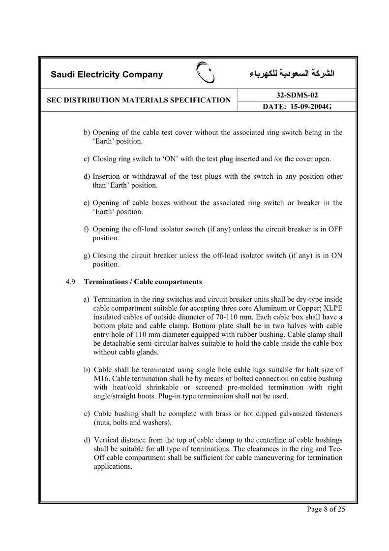
4.9 Terminations / Cable compartments
a) Termination in the ring switches and circuit breaker units shall be dry-type inside cable compartment suitable for accepting three core Aluminum or Copper; XLPE insulated cables of outside diameter of 70-110 mm. Each cable box shall have a bottom plate and cable clamp. Bottom plate shall be in two halves with cable entry hole of 110 mm diameter equipped with rubber bushing. Cable clamp shall be detachable semi-circular halves suitable to hold the cable inside the cable box without cable glands.
b) Cable shall be terminated using single hole cable lugs suitable for bolt size of
M16. Cable termination shall be by means of bolted connection on cable bushing with heat/cold shrinkable or screened pre-molded termination with right angle/straight boots. Plug-in type termination shall not be used.
c) Cable bushing shall be complete with brass or hot dipped galvanized fasteners
(nuts, bolts and washers). d) Vertical distance from the top of cable clamp to the centerline of cable bushings
shall be suitable for all type of terminations. The clearances in the ring and Tee-Off cable compartment shall be sufficient for cable maneuvering for termination applications.

Saudi Electricity Company الشرآة السعودية للكهرباء
32-SDMS-02 SEC DISTRIBUTION MATERIALS SPECIFICATION DATE: 15-09-2004G
Page 9 of 25
e) The design of the cable compartments shall be such that their covers with
sidewalls shall be removed to have full access during cable termination. f) Removal and installation of cable compartment covers shall be with minimum
number of bolts. 4.10 Earthing
A ground bar of not less than 25 x 5 mm copper strip shall be provided bolted to the frame. It shall be located so as to facilitate earthing of cable sheaths and earthing devices. In addition, a terminal having M12 stud and nut shall be provided in the back of the panel with clear grounding mark.
4.11 Voltage Indicators / Phase Comparators
Built-in push-button or continuous indication without push-button type neon voltage indicators shall be provided together with low voltage hot phasing facility on ring switches and circuit breaker panels. The lamps shall be powered by bushing type capacitive voltage dividers. Internal wiring in cable boxes shall be covered with heat resistant tape/tube, to protect it against flame temperature of gas torch during the cable termination.
4.12 Earth Fault Indicator (EFI)
Earth fault indicator (SEC approved type) with automatic resetting on 220-230V single-phase AC supply, split core type sensor of internal diameter not less than 130 mm shall be supplied. EFI shall be protected inside separate sunshield cover with a mesh front (drawn from the same metal sheet). EFI shall be installed on the left-hand side line-feeder. It shall be with two auxiliaries contacts, one for light signal and the other for remote monitoring. Three-pin plug for testing of EFI by primary current injection shall be provided in separate compartment with screwed cover, below the EFI housing. SEC may require to supply the EFI loose in an outdoor box with 10 meters of control cable for installation on masonry wall.
4.13 Auxiliaries supply
The MRMU shall not require any external auxiliary AC/DC power supply for operation and control. This power supply shall be obtained from a cast resin insulated voltage transformer connected to bus-bar side. Its secondary output shall be 220 V AC and capacity shall be adequate for spring charging motors, switching operations, status indications, protective relays, necessary contactors for control and

Saudi Electricity Company الشرآة السعودية للكهرباء
32-SDMS-02 SEC DISTRIBUTION MATERIALS SPECIFICATION DATE: 15-09-2004G
Page 10 of 25
monitoring of ring switches and circuit breaker panels and load management devices.
4.14 Load Management System
The unit shall be equipped with a management system that permits the control and monitoring of the consumer's load during normal conditions and peak time. In normal conditions, and if the consumer exceeds the contracted load (in KVA), the system shall be capable of giving alarm then trips the breaker after a preset time delay. During peak time, if the consumer exceeds the load previously determined by SEC, the system shall be capable of giving alarm and tripping / closing the breaker in a sequence and time delay provided by SEC. The system shall restore the power automatically after the peak period is over without the intervention of any operator. The minimum setting to trip the breaker during peak period shall correspond to 500 KVA of consumer's load.
4.15 Metering and protection equipment 4.15.1 Two single phase voltage transformers according to IEC-60044-2 shall be fitted at
the feeder side of the circuit breaker for metering purpose. They shall be dry type, epoxy encapsulated rated as follows: - Voltage: 13.8 kV / 110 V or 33 kV / 110 V - Frequency: 60 Hz - Burden: 100 VA - Class: 1
4.15.2 Double-ratio primary current transformers for protection and metering according
to IEC-60044-1 and SEC specification 50-SDMS-01 shall be fitted in the circuit breaker panel. They shall be dry type, epoxy encapsulated rated as follows: - Current ratio: 400/200/5-5 A - Burden: For protection: 15 VA For metering: 10 VA - Class: For protection: 5P10 For metering: 0.5
4.16 Terminal blocks 4.16.1 Terminal blocks for remotely installed three phase three-wire revenue KWH meter
shall be provided, identified and clearly marked. These terminal blocks shall have CT shorting and voltage disconnection facility without disturbing the wiring connections.

Saudi Electricity Company الشرآة السعودية للكهرباء
32-SDMS-02 SEC DISTRIBUTION MATERIALS SPECIFICATION DATE: 15-09-2004G
Page 11 of 25
4.16.2 Terminal blocks for current injection test facility for protective relay shall be
provided, identified and clearly marked. 4.16.3 Terminal blocks for remotely installed alarm shall be provided, to indicate
exceeding of the allowed load during the peak period. 4.17 Indicating meters
Indicating meters for three phase current and voltage with phase selector switches shall be provided. Current indicating meters shall be provided with 15 minutes maximum demand indicator.
4.18 Over-pressure Release
In order to ensure maximum personal safety, Metered Ring Main Unit shall be designed to withstand any overpressure due to an internal fault by rupture of a gas escape membrane located at the rear or bottom of the enclosure. The gas shall be led out through a flap in the rear panel to the bottom of the enclosure.
4.19 Nameplate
The switchgear shall be provided with Aluminum /Stainless steel / Brass nameplate showing the following information indelibly marked in Arabic and English:
• Manufacturer’s Name • Country of Origin • Type/Model • Vendor’s Name • Reference of SEC specification • Manufacturer’s Serial Number • SEC Purchase Order Number • SEC Item Number • Year of Manufacture • Voltage Rating kV • Current Rating Amps • BIL kV • Short Circuit Rating / Duration kA / Sec • Rated Frequency 60Hz • Rated Making Current kA • Rated Breaking Current kA • Gross Weight kg

Saudi Electricity Company الشرآة السعودية للكهرباء
32-SDMS-02 SEC DISTRIBUTION MATERIALS SPECIFICATION DATE: 15-09-2004G
Page 12 of 25
4.20 Circuit Labels
Ring switches and circuit breaker panels shall be provided with circuit number plates of dimension 150 x 50 mm without inscription. Plate shall be made of three-layer traffolyte material (white/black/white) of 3 mm thickness as per SEC drawing No. SEC-01- 03.
4.21 Monograms and Danger Plates
Danger plate and SEC monogram as per SEC drawings No. SEC-01-01 and SEC-01-02 respectively shall be provided and installed at the front panel (on SEC approved location) of the switchgear using M5 hot dipped galvanized / stainless steel / brass fasteners (oval head rounded neck bolts with nuts and external tooth lock washers) not removable / accessible from the front i.e. without opening the door / front cover. SEC shall approve location and samples of danger & monogram plates prior to installation.
5.0 TESTING AND INSPECTION
5.1 All equipment shall be type tested at an independent laboratory in accordance with
the latest standards and as specified herein and test report shall be submitted for SEC review and approval.
5.2 The switchgear offered shall meet the type test requirements of the standards listed below:
5.2.1 High-voltage switches per IEC 60265 a) Dielectric Tests b) Temperature Rise Tests c) Making and Breaking Tests d) Peak and Short Circuit Withstand Current Tests e) Operation and Mechanical Endurance Tests f) Internal arc test certificate
5.2.2 Circuit- breaker per IEC 60056 a) Dielectric Tests b) Temperature Rise Tests c) Measurement of the resistance of the main circuit d) Short-time and Peak Withstand Current Tests e) Mechanical and Environmental Tests f) Making and Breaking Tests

Saudi Electricity Company الشرآة السعودية للكهرباء
32-SDMS-02 SEC DISTRIBUTION MATERIALS SPECIFICATION DATE: 15-09-2004G
Page 13 of 25
g) Short-circuit Tests
5.2.3 Degree of protection IP41 per IEC 60529
5.3 The switchgear offered shall meet the routine test requirements of the standards listed below:
5.3.1 High-voltage switches per IEC 60265 a) Power Frequency Voltage Tests b) Voltage Tests on Auxiliary Circuits c) Measurement of Resistance of Main Circuit d) Operation Tests e) Operation and Mechanical Endurance Tests
5.3.2 Circuit breaker per IEC 60056 a) Power Frequency Voltage Tests b) Voltage Withstand Tests on Control and Auxiliary Circuits c) Measurement of Resistance of Main Circuit d) Mechanical Operating Tests
5.4 SEC reserve the right to visit the factory during manufacture of any or all items covered by this specification, for inspection of material or witness of tests. Accordingly, the manufacturer shall give SEC adequate notice of manufacturing and testing schedule.
6.0 PACKING AND SHIPMENT
6.1 The switchgear shall be delivered ready for installation (three panels fitted together). 6.2 Switchgear shall be individually packed in non-returnable cases as per packing/
shipping requirements in relevant clauses of 01-SDMS-01.
6.3 For container shipment, switchgear bolted on wood pallet is acceptable. 6.4 Units shall be supplied complete with all operation and installation accessories.
7.0 GUARANTEE
7.1 The vendor shall guarantee the metered ring main unit against all defects arising out
of faulty design or workmanship or defective material for a period of two years from the date of delivery.

Saudi Electricity Company الشرآة السعودية للكهرباء
32-SDMS-02 SEC DISTRIBUTION MATERIALS SPECIFICATION DATE: 15-09-2004G
Page 14 of 25
7.2 Warranty period for gas tightness shall conform to clause 5.15.3 of IEC 60694. For
the maintenance-free version the vendor / manufacturer shall assume full responsibility for no gas leakage during the service life. In case of gas leak during the service life, all expenses for repairs and replacements shall be borne by vendor / manufacturer.
7.3 If no exception to this specification and no list of deviations are submitted, it shall
be deemed that, in every respect, metered ring main unit offered shall conform to this specification. SEC interpretation of this specification shall be accepted.
8.0 SUBMITTALS
8.1 Vendor shall complete and return one copy of the attached Technical Data
Schedule. 8.2 Vendor shall provide the following with the Quotation:
• Clause by clause compliance with this specification. • Drawing showing the full constructional detail with dimensions of metered
rings main unit and all associated accessories. • Drawing of mounting details with respect to the position of cables in the
switchgear room. • Drawings of cable boxes. • Installation and maintenance instructions of the metered ring main unit. • Comprehensive list of manufacturer’s recommended spare parts. The
quantities offered should be adequate for the initial 5 years of operation. Firm price and delivery period shall be quoted for each item.
• Copy of type test report. • A certificate from the termination manufacturers that the cable box size in all
respect (technical, cable handling and making termination) is suitable for heat & cold shrink and pre-mold terminations
• Descriptive leaflet and literature of metered ring main unit offered. • Checklist of quotation request. • List of customers in case of new manufacture / vendor.
8.3 Vendor shall provide the following after signing of purchase order:
• Details of manufacturing and testing schedules. • Routine test reports.
Saudi Electricity Company الشرآة السعودية للكهرباء
32-SDMS-02 SEC DISTRIBUTION MATERIALS SPECIFICATION DATE: 15-09-2004G
Page 15 of 25
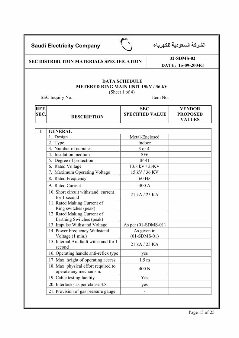
DATA SCHEDULE
METERED RING MAIN UNIT 15kV / 36 kV (Sheet 1 of 4)
SEC Inquiry No. _________________________________ Item No. _____________
REF. SEC.
DESCRIPTION
SEC SPECIFIED VALUE
VENDOR PROPOSED
VALUES
1 GENERAL 1. Design Metal-Enclosed 2. Type Indoor 3. Number of cubicles 3 or 4 4. Insulation medium SF6 5. Degree of protection IP-41 6. Rated Voltage 13.8 kV / 33KV 7. Maximum Operating Voltage 15 kV / 36 KV 8. Rated Frequency 60 Hz 9. Rated Current 400 A 10. Short circuit withstand current
for 1 second 21 kA / 25 KA
11. Rated Making Current of Ring switches (peak) -
12. Rated Making Current of Earthing Switches (peak) -
13. Impulse Withstand Voltage As per (01-SDMS-01) 14. Power Frequency Withstand
Voltage (1 min.) As given in
(01-SDMS-01)
15. Internal Arc fault withstand for 1 second 21 kA / 25 KA
16. Operating handle anti-reflex type yes 17. Max. height of operating access 1.5 m 18. Max. physical effort required to
operate any mechanism. 400 N
19. Cable testing facility Yes 20. Interlocks as per clause 4.8 yes 21. Provision of gas pressure gauge -

Saudi Electricity Company الشرآة السعودية للكهرباء
32-SDMS-02 SEC DISTRIBUTION MATERIALS SPECIFICATION DATE: 15-09-2004G
Page 16 of 25
DATA SCHEDULE METERED RING MAIN UNIT 15kV / 33 KV
(Sheet 2 of 4) SEC Inquiry No. _________________________________ Item No. _____________
2 CIRCUIT BREAKER
1. Type Fixed 2. Insulation medium SF6 3. Interruption medium SF6 or Vacuum 4. Rated Voltage 13.8 kV / 33 KV 5. Maximum Operating Voltage 15 kV / 36 KV 6. Rated Frequency 60 Hz 7. Rated Current of CB 400A 8. Rated Short circuit level (1 s) 21 kA / 25 KA 9. Rated Making Current 10. Re-striking Voltage Ratio 11. Duty Cycle 12. Making time 13.Opening time 14. Arc Duration 15. Total Breaking Time 16. Operating Mechanism Spring Charged 17. Protective E/F & O/C relay As per attached appendix 18. Provision of isolator switch -
3 TERMINATIONS / CABLE COMPARTMENTS 1. Cable compartment with bottom
plate and cable clamp
yes
2. To accept cable with 70-100 mm diameter yes
3. Bottom plate in two halves with 110 mm hole yes
4. Fasteners supplied with bushing yes 5. Bolt size for cable termination M16 6. Type of termination Dry type heat /cold /
pre-moulded
7. Clearance between clamp and bushing
Suitable for all type of terminations

Saudi Electricity Company الشرآة السعودية للكهرباء
32-SDMS-02 SEC DISTRIBUTION MATERIALS SPECIFICATION DATE: 15-09-2004G
Page 17 of 25
DATA SCHEDULE
METERED RING MAIN UNIT 15kV / 33 KV (Sheet 3 of 4)
SEC Inquiry No. _________________________________ Item No. _____________
4 ACCESSORIES 1. Ground bar 25x5 mm & M12 stud yes 2. Voltage indicator lamps yes 3. Phase comparators yes 4. Approved type EFI yes 5. Self powered switch ( doesn’t
require external auxiliary supply ) yes
6. Load management system yes 7. Voltage transformers rated as per
clause 4.15.1 yes
8. Current transformers rated as per clause 4.15.2 yes
9. Terminal blocks for KWH meter, relay testing and alarm provided yes
10. Indicating meters yes 11. Over-pressure release yes 12. Name plate yes 13. Circuit labels yes 14. SEC Monogram yes 15.Danger plate yes
5 CUBICLE 1. Maximum height 2400 mm 2. max width of CB panel 1000 mm 3. max width of LBS panel 750 mm 4. Depth suitable for 600 mm cable
trench yes
5. Paint finish Method 6. Finish Color RAL 7033

Saudi Electricity Company الشرآة السعودية للكهرباء
32-SDMS-02 SEC DISTRIBUTION MATERIALS SPECIFICATION DATE: 15-09-2004G
Page 18 of 25
DATA SCHEDULE
METERED RING MAIN UNIT 15kV / 33 KV (Sheet 4 of 4)
SEC Inquiry No. _________________________________ Item No. _____________
A. ADDITIONAL TECHNICAL INFORMATION OR FEATURES SPECIFIED BY SEC:
B. ADDITIONAL SUPPLEMENTARY DATA OR FEATURES PROPOSED BY
BIDDER/VENDOR/SUPPLIER: C. OTHER PARTICULARS TO BE FILLED UP BY BIDDER/VENDOR/
SUPPLIER: D. LIST OF DEVIATIONS & CLAUSES TO WHICH EXCEPTIONS ARE
TAKEN BY THE BIDDER/VENDOR/SUPPLIER: (USE SEPARATE SHEET IF NECESSARY)
MANUFACTURER OF
MATERIALS/EQUIPMENTVENDOR / SUPPLIER
Name of Company
Location and Office Address
Name and Signature of Authorize Representative
Official Seal / Stamp

Saudi Electricity Company الشرآة السعودية للكهرباء
32-SDMS-02 SEC DISTRIBUTION MATERIALS SPECIFICATION DATE: 15-09-2004G
Page 19 of 25
APPENDIX
Specifications of Phase and Ground Over current Protective Relays with Low set (Time Delay) and High-set (Instantaneous) Elements (50/51,50N/51N) for RMUs 1.0 General 1.1 The relay shall be microprocessor based numerical type. 1.2 All the components, hardware, input/output devices of the relay shall comply with relevant
IEC or equivalent standards. 1.3 The relay shall use thoroughly tested software and hardware to IEC or equivalent
standards. Relay should have acquired at least two (2) years of field experience in a major electric utility.
1.4 All the input/output units of the relay shall be capable of making/breaking currents (with
any transients) and withstand voltages (normally intended/harmonic over voltages). 1.5 The relay shall be immune to all types of electrical and mechanical interference in
accordance with relevant IEC standard or equivalent. 1.6 It shall have communication interface for remote control functions. 1.7 It shall have Inrush current/harmonic restraint features. 1.8 The relay shall be self-powered from RMU CTs or provided with its own power supply.
Relays requiring external power supply are not acceptable. 1.9 The degree of protection of the relay enclosure shall be of class IP 54 or better. Relay shall
be suitable for outdoor installations in extreme heat and dusty conditions without affecting its normal performance.
2.0 Application 2.1 The relay shall consist of three (3) 1-phase over current unit and one (1) ground fault unit
and suitable for 5A or 1A CT secondary current. 2.2 Each phase and ground unit shall consist of Low-set (Time Delay) element and High-set
(Instantaneous) element.
2.3 Low-set (Time Delay) element of both phase and ground fault units shall have:

Saudi Electricity Company الشرآة السعودية للكهرباء
32-SDMS-02 SEC DISTRIBUTION MATERIALS SPECIFICATION DATE: 15-09-2004G
Page 20 of 25
Appendix: Page 2 of 4 2.3.1 Selectable inverse time characteristics according to IEC 255 or BS142. 2.3.2 Selectable pickup setting 2.3.3 Selectable time multiplier setting 2.4 High-set (Instantaneous) element of the phase and ground units shall have: 2.4.1 Separate target 2.4.2 Selectable setting 2.4.3 Provision to disable the element through front panel commands/settings or software. 2.5 The relay shall have: 2.5.1 Low-set Phase Over current Relay Pickup range: 30% to 240% of relay rated current
in steps of 10%. 2.5.2 Low-set Ground Over current Relay Pickup range: 10% to 100% of relay rated current
in steps of 10%.
2.5.3 Time multiplier range of 0.1 to 1.2s for the phase and ground over current in steps of 0.05.
2.5.4 High-set Phase over current relay pickup range: 100% to 3200% of relay rated current
in steps of 50%
2.6 The relay shall be:
2.6.1 Suitable for operating on 60 Hz
2.6.2 Suitable for solidly / low resistance grounded system 2.6.3 Provide with high intensity LED target indicators for the low-set and high-set elements

Saudi Electricity Company الشرآة السعودية للكهرباء
32-SDMS-02 SEC DISTRIBUTION MATERIALS SPECIFICATION DATE: 15-09-2004G
Page 21 of 25
Appendix: Page 3 of 4
2.7 The relay AC circuits shall withstand continuous current of 3 x In (where In is the relay
rated current), a current of 20 x In for 10 sec. and a current of 70 x In for 1 sec. 2.8 The relay shall have high dropout to pickup ratio and transient overreaching for
instantaneous unit shall be less than 5%. The relay shall impose low burden on CTs. 2.9 The relay and CTs should be compatible with each other and supplied as one integrated
package. 3.0 Testing 3.1 The relays shall be tested in accordance with the requirements of IEC or equivalent ANSI,
British, etc. 3.2 The relays shall be capable of being functionally tested completely, with adequate safety
without the risk of spurious tripping, per standard test connections, using secondary injection test sets.
3.3 The relay shall have external testing facilities. The design of the test terminals/plugs shall
be such that external test equipment can be connected at a conveniently located connector on the relay panel.
4.0 Instruction and Maintenance Manual 4.1 Original Manufacturer’s Instruction Manuals and Documentation shall be provided. 4.2 The information in the manuals and documentation for the relay shall include but not l
limited to the following: 4.2.1 Specification and Characteristics and available functions 4.2.2 Relay limitations 4.2.3 External Connections 4.2.4 Any special device for testing/calibrating the relay shall be mentioned 4.2.5 Description, drawings of the construction and principals of operation.
Saudi Electricity Company الشرآة السعودية للكهرباء
32-SDMS-02 SEC DISTRIBUTION MATERIALS SPECIFICATION DATE: 15-09-2004G
Page 22 of 25
Appendix: Page 4 of 4 4.2.6 All setting Calculation Procedures and Instructions 4.2.7 Installation Requirements and Instructions 4.2.8 Routine Maintenance Requirements and Instructions 4.2.9 Repair and re-calibration Instructions 4.2.10 Parts List 4.2.11 Certified Test Reports

Saudi Electricity Company الشرآة السعودية للكهرباء
32-SDMS-02 SEC DISTRIBUTION MATERIALS SPECIFICATION DATE: 15-09-2004G
Page 23 of 25

Saudi Electricity Company الشرآة السعودية للكهرباء
32-SDMS-02 SEC DISTRIBUTION MATERIALS SPECIFICATION DATE: 15-09-2004G
Page 24 of 25

Saudi Electricity Company الشرآة السعودية للكهرباء
32-SDMS-02 SEC DISTRIBUTION MATERIALS SPECIFICATION DATE: 15-09-2004G
Page 25 of 25