Embed Size (px)
Citation preview
2327-4662 (c) 2017 IEEE. Personal use is permitted, but republication/redistribution requires IEEE permission. See http://www.ieee.org/publications_standards/publications/rights/index.html for more information.
This article has been accepted for publication in a future issue of this journal, but has not been fully edited. Content may change prior to final publication. Citation information: DOI 10.1109/JIOT.2017.2779180, IEEE Internet ofThings Journal
1
SDN-based Data Transfer Security for Internet ofThings
Yanbing Liu, Yao Kuang, Yunpeng Xiao, and Guangxia Xu
Abstract—The exponential growth of devices connected to thenetwork has resulted in the development of new Internet ofThings (IoT) applications and on-line services, which may havediverse and dynamic requirements on received quality. Although,the emerging Software-Defined Networking (SDN) approach canbe leveraged for the IoT environment, to dynamically achievedifferentiated quality levels for different IoT tasks in veryheterogeneous wireless networking scenarios, the open interfacesin SDN introduces new network attacks, which may make SDN-based IoT malfunctioned. The challenges lies in securely usingSDN for IoT systems. To address this challenge, we design aSDN-based data transfer security model Middlebox-Guard (M-G). M-G aims at reducing network latency, and properly managedataflow to ensure the network run safely. First, according todifferent security policies, middleboxes related to the definedsecure policies, are placed at the most appropriate locations, usingdataflow abstraction and a heuristic algorithm. Next, to avoidany middlebox becoming a hot-spot, an offline Integer LinearProgram (ILP) pruning algorithm is proposed in M-G, to tackleswitch volume constraints. In addition, an online Linear Program(LP) formulation is come up to handle load balance. Finally,secure mechanisms are proposed to handle different attacks. Andnetwork routing is solved flexibly, through dataflow managementprotocol, which are formulated via combining tunnels and tags.Experimental results demonstrate that this model can improvesecurity performance and manage dataflow effectively in SDN-based IoT system.
Index Terms—Internet of Things; Software-Defined Network-ing; Middlebox; Dataflow Management; Security.
I. INTRODUCTION
THE continued evolution of new services and the growthof the information circulating the Internet, has led to the
origin of ideas, concepts and paradigms such as the Internet ofThings (IoT)[1]. However, traditional network infrastructure,
Manuscript received XXXXXXXXXXXXX. This work has been support-ed by the National Science Foundation of China (Grant No.61772098&61772099), Chongqing Innovative Team Fund for College DevelopmentProject (Grant No.KJTD201310), Chongqing Youth Innovative Talent Project(Grant No.cstc2013kjrc-qnrc40004), Science and Technology Research Pro-gram of the Chongqing Municipal Education Committee (No.KJ1500425),WenFeng and Foundation of CQUPT(No.WF201403) and Chongqing Gradu-ate Research And Innovation Project(No.CYS14146).
Yanbing Liu is with Chongqing Engineering Laboratory of Internet andInformation Security Chongqing University of Posts and Telecommunications,Chongqing, 400065 China (e-mail: [email protected]).
Yao Kuang is with Chongqing Engineering Laboratory of Internet andInformation Security Chongqing University of Posts and Telecommunications,Chongqing, 400065 China (e-mail: [email protected]).
Yunpeng Xiao is with Chongqing Engineering Laboratory of Internet andInformation Security Chongqing University of Posts and Telecommunications,Chongqing, 400065 China (e-mail: [email protected]).
Guangxia Xu is with the School of Software Engineering, ChongqingUniversity of Posts and Telecommunications, Chongqing 400065, China (e-mail: [email protected]).
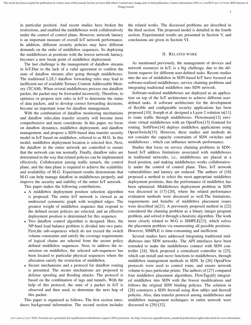
which need high-level network policies and configuring proto-cols, are inefficient and have significant limitations to supportthe high level of scalability, high amount of traffic and mo-bility. Software-Defined Networking(SDN)[2] decouples thetraditional closed network into data plane, control plane andapplication plane, which enables logically centralized controland management of the whole network. With this new designprinciple, the network could behave more flexibly and caneasily adapt to the needs of different organizations. Besides,the centralized architecture allows important information to becollected from the network and in turn used to improve andadapt their policies dynamically. Thus, as shown in Figure1, a programmable, flexible, flow-centric SDN-based IoTarchitecture is favorable. Although, open interfaces in SDNhave simplified the design of secure applications in large andcomplex IoT, they are vulnerable to new network attacks [3]-[4], and this vulnerability inevitably reduces security in SDN-based IoT architecture. In IoT, the dataflow has to go through
Fig. 1. SDN-based IoT architecture.
several processes before all required tasks are finished. Thus,proper handling of data flows in each device, is important forstable and secure network operation. Recent studies about theuse of middleboxe and SDN[5]-[9] fall into three categories,including software realized middlebox, service chaining prob-lems and integrating traditional middlebox into SDN networks.
The first challenge is the dynamic of dataflow in IoT.Thenumber of users and dataflow volume in IoT vary over time.However, most existing dataflow control techniques assume astable network. Therefore, such techniques can not activelyconsider network security. If a large number of data streamsarrive simultaneously, the entire IoT network may becomeparalyzed. Thus, when developing dataflow control strategies,considering dataflow streams dynamics can improve the secu-rity and stability of the entire network.
The second challenge is the deployment of middleboxesin IoT.In traditional networks, the middlebox is deployed
2327-4662 (c) 2017 IEEE. Personal use is permitted, but republication/redistribution requires IEEE permission. See http://www.ieee.org/publications_standards/publications/rights/index.html for more information.
This article has been accepted for publication in a future issue of this journal, but has not been fully edited. Content may change prior to final publication. Citation information: DOI 10.1109/JIOT.2017.2779180, IEEE Internet ofThings Journal
2
in particular position. And recent studies have broken therestrictions, and enabled the middleboxes work collaborativelyunder the control of control plane. However, network latencyis an important measure of overall IoT network performance.In addition, different security policies may have differentdemands on the order of middlebox sequences. So deployingthe middleboxes at positions with the lowest network latency,becomes a new break point of middlebox deployment.
The last challenge is the management of dataflow streamsin IoT.Due to the lack of a valid agreement to confirm thestate of dataflow streams after going through middleboxes.The traditional L2/L3 dataflow forwarding rules may lead toinefficient use of available Ternary Content Addressable Mem-ory (TCAM). When several middleboxes process one dataflowpacket, the packet may be forwarded incorrectly. Therefore, tooptimize or propose new rules in IoT to determine the statusof data packets, and to develop correct forwarding decisions,become an important issue for dataflow management.
With the combination of dataflow monitoring mechanismsand dataflow rules,data transfer security will become morecomprehensive and more considerate. In this paper, we focuson dataflow dynamics, middlebox deployment, and dataflowmanagement, and propose a SDN-based data transfer securitymodel in IoT based on middlebox, referred to as M-G. In thismodel, middlebox deployment location is selected first. Next,the dataflow in the entire network are controlled to ensurethat the network can run normally. Finally, dataflow rules aredetermined in the way that related policies can be implementedeffectively. Collaboration among traffic tunnels, the controlplane, and the data plane is required to achieve the scalabilityand availability of M-G. Experiment results demonstrate thatM-G can help manage dataflow in middleboxes properly, andimprove the security and stability of the entire IoT network.
This paper makes the following contributions.• A middlebox deployment position selection algorithm
is proposed. The entire IoT network is viewed as anundirected symmetric graph with weighted edges. Thegreatest weight of middlebox sequence that respond tothe defined secure policies are selected, and an effectivedeployment position is determined for this sequence.
• Two dataflow control algorithm is designed. Here, theNP-hard load balance problem is divided into two parts.First,the sub-sequences which do not exceed the switchvolume constraints and satisfy the coverage requirementsof logical chains are selected from the secure policydefined middlebox sequences. Next, to address the re-striction on middlebox, the selected sub-sequences hasbeen located to particular physical sequences where theallocation satisfy the restriction of middlebox.
• Secure mechanisms and a protocol for dataflow routingis presented. The secure mechanisms are proposed todefense spoofing and flooding attacks. The protocol isbased on the combination of tags and tunnels. With thehelp of this protocol, the state of a packet in IoT isobserved and then used, to determine the next hop ofthis packet.
This paper is organized as follows. The first section intro-duces background information. The second section includes
the related works. The discussed problems are described inthe third section. The proposed model is detailed in the fourthsection. Experimental results are presented in Section V, andconclusions are given in Section VI.
II. RELATED WORK
As mentioned previously, the management of devices andnetwork resources in IoT, is a big challenge, due to the dif-ferent requests for different user-defined tasks. Recent studiesinto the use of middlebox in SDN-based IoT have focused onsoftware-realized middleboxes, service chaining problems andintegrating traditional middlebox into SDN network.
Software-realized middleboxes are deployed as an applica-tion on top of the IoT architecture to achieve different user-defined tasks. A software architecture for the developmentof flexible and configurable security applications has beenproposed [10]. Joseph et al. designed a Layer-2 solution in[11]to route traffic through middleboxes. Flowstream[12] envi-sions virtual middleboxes with an OpenFlow[13] frontend forrouting. SoftFlow[14] deploys middlebox applications usingOpenvSwitch[15]. However, these studies and methods donot consider the capacity constraints of SDN switches andmiddleboxes , which can influence network performance.
Studies that focus on service chaining problems in SDN-based IoT address limitations associated with middleboxesin traditional networks, i.e., middleboxes are placed at afixed position, and making middleboxes works collaborative-ly under the control of control plane. Thus, IoT networkvulnerabilities and latency are reduced. The authors of [16]proposed a method to select the most appropriate middleboxdeployment positions, thus the performance of middlebox hasbeen optimized. Middleboxes deployment problem in SDNwas discussed in [17]-[20], where the related performanceevaluation methods were discussed as well.The limitations,requirements and benefits of middlebox placement issueswere described in[21]. A previously proposed method in [22]considered the chaining problem as a binary integer programproblem, and solved it through a heuristic algorithm. The workmore closely related to M-G is SIMPLE[23], which solvesthe placement problem via enumerating all possible positions.However, SIMPLE is time-consuming and inefficient.
Several studies have addressed integrating traditional mid-dleboxes into SDN networks. The API interfaces have beenextended to make the middleboxes connect with SDN con-troller [24]. Slick proposed a centralized controller in [25],which can install and move functions to middleboxes, throughmiddlebox management methods in SDN. In [26] OpenFlowprotocols were used to control route, and ensure networkvolume to pass particular points. The authors of [27] comparedfour middlebox placement algorithms. FlowTags[6] integrat-ed middlebox into SDN with the fewest modifications andfollows the original SDN binding policies. The solution in[28] constructs a SDN firewall using flow tables and firewallpolicies. Also, data transfer protocol among middleboxes andmiddlebox management techniques in entire network werediscussed in [29]-[32].
2327-4662 (c) 2017 IEEE. Personal use is permitted, but republication/redistribution requires IEEE permission. See http://www.ieee.org/publications_standards/publications/rights/index.html for more information.
This article has been accepted for publication in a future issue of this journal, but has not been fully edited. Content may change prior to final publication. Citation information: DOI 10.1109/JIOT.2017.2779180, IEEE Internet ofThings Journal
3
III. PROBLEM FORMALIZATION
A. Related Definitions
For convenience, the used symbols are shown in table1.The proposed framework attempts to solve the following
problems: 1) How to place middleboxes such as firewallintrusion detection systems (IDS) into SDN-based IoT system.2) How to guarantee that the flow streams in middleboxesand switches do not exceed their capacity limits, in order tofacilitate stable IoT network operation. Several definitions aregiven below as the basis of algorithm design and functionalcombination scheme.e basis of algorithm design and functionalcombination scheme.
Definition 1. G(N,A): The entire IoT network can be con-sidered as an undirected graph G(N,A), where N is the set ofswitches and A is the set of links.
Definition 2. Processing policy: The secure policy is bestexpressed via a dataflow abstraction. The operator who op-erate the network annotate each policy (e.g. <External, We-b>) with its ingress and egress locations and IP prefix-es. For example, a external web traffic may be specifiedby a traffic filter such as:<src=internal prefix, dst=externalprefixes,srcport=*,dstport=80,proto=TCP>. Here, PoChainc
denotes the required middlebox policy chain for this class(e.g.Firewall-IDS)
Definition 3. Successor nodes SCS(i): for node i and j, ifaij ∈ A , node j is the successor node of node i.
Definition 4. Dependency degree: two middleboxes aredependent if they appear consecutively in a policy chain, andthe dependency degree is determined based on the amount oftraffic with such middlebox chain requirement.
Definition 5. Given two different paths priu ̸= priv from anorigin node r to a node i, priu FSD dominates priv if the inverseCDF of the link travel time distribution at λ confidence levelsatisfies ϕ−1
T riu (yr)(λ) < ϕ−1
T riv (yr)(λ), ∀λ ∈ (0, 1).
Definition 6. Nondominate road DL; A path considerednondominated if it can not be FSD dominated by any otherpath.
FWIDS
Proxy
S1
S2
S3
S4S6
S5
Inadd. Outadd.
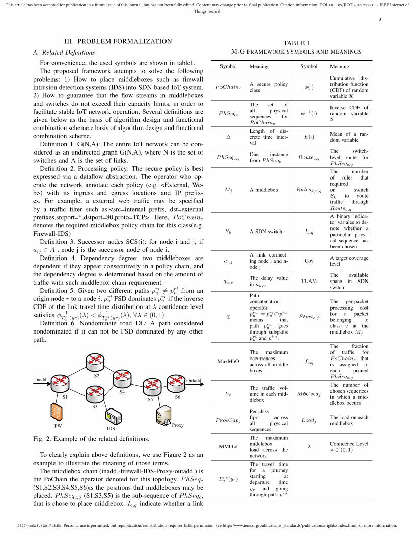
Fig. 2. Example of the related definitions.
To clearly explain above definitions, we use Figure 2 as anexample to illustrate the meaning of those terms.
The middlebox chain (inadd.-firewall-IDS-Proxy-outadd.) isthe PoChain the operator denoted for this topology. PhSeqc(S1,S2,S3,S4,S5,S6)is the positions that middleboxes may beplaced. PhSeqc,q (S1,S3,S5) is the sub-sequence of PhSeqc,that is chose to place middlebox. Ic,q indicate whether a link
TABLE IM-G FRAMEWORK SYMBOLS AND MEANINGS
Symbol Meaning Symbol Meaning
PoChaincA secure policyclass
ϕ(·)Cumulative dis-tribution function(CDF) of randomvariable X
PhSeqc
The set ofall physicalsequences forPoChainc
ϕ−1(·)Inverse CDF ofrandom variableX
∆Length of dis-crete time inter-val
E(·) Mean of a ran-dom variable
PhSeqc,qOne instancefrom PhSeqc
Routec,qThe switch-level route forPhSeqc,q
Mj A middlebox Rulesk,c,q
The numberof rules thatrequiredon switchSk to routetraffic throughRoutec,q
Sk A SDN switch Ic,q
A binary indica-tor variales to de-note whether aparticular physi-cal sequence hasbeen chosen
ai,jA link connect-ing node i and n-ode j
Cov A target coveragelevel
qu,vThe delay valuein au,v
TCAMThe availablespace in SDNswitch
⊕
Pathconcatenationoperatorprwu = priu ⊕piw
means thatpath prwu goesthrough subpathspriu and piw .
Ftprtc,j
The per-packetprocessing costfor a packetbelonging toclass c at themiddlebox Mj
MaxMbO
The maximumoccurrencesacross all middleboxes
fc,q
The fractionof traffic forPoChainc thatis assigned toeach prunedPhSeqc,q
Vc
The traffic vol-ume in each mid-dlebox
MbUsedj
The number ofchosen sequencesin which a mid-dlebox occurs
ProcCapj
Per-classftprt acrossall physicalsequences
LoadjThe load on eachmiddlebox
MMbLd
The maximummiddleboxload across thenetwork
λConfidence Levelλ ∈ (0, 1)
T rsu (yr)
The travel timefor a journeystarting atdeparture timeyr and goingthrough path prs
2327-4662 (c) 2017 IEEE. Personal use is permitted, but republication/redistribution requires IEEE permission. See http://www.ieee.org/publications_standards/publications/rights/index.html for more information.
This article has been accepted for publication in a future issue of this journal, but has not been fully edited. Content may change prior to final publication. Citation information: DOI 10.1109/JIOT.2017.2779180, IEEE Internet ofThings Journal
4
has been chosen, in figure 2 I1,2 is 0, and I1,3 is 1. InPhSeqc,q (S1,S3,S5) the number of MbUsedj is 3, becausethere are three middleboxes in t.he chose sequence. AndMaxMbO is the maximum number of all MbUsedj in theentire network, here it is 3, because there is only one sequence.Frprtc,j is the cost that a middlebox need to processing apacket. ProcCapj is the Ftprt across sequence S1-S3-S5.
B. Problem
Due to the reasons that network latency is important tomeasure network performance, and properly management ofdataflow is the key to ensure network security. To reduce thenetwork latency, the used middleboxes need to be placed atthe locations, where the communication link is the shortest.To ensure the entire network can run stably and securely, thedataflow should be properly managed. The following problemswill be investigated in this paper.
• How to find the most appropriate position for middle-box? Through dataflow abstraction, we annotate eachpolicy (e.g. <External, Web>) with its ingress and egresslocations and IP prefixes. And the most appropriatemiddlebox deployment location PhSeqc,q is selected byour heuristic algorithm.
• How to ensure that dataflow in the entire IoT network donot exceed switch and middlebox capacity, to avoid any s-ingle piece of equipment from becoming a hotspot? First,switch constraints is tackled. Here, MaxMbO, the max-imum occurrences of middleboxes in a physic sequencePhSeqc,q is minimized to obtain the most appropriateroute. Next, network loads is balanced. We run linearprogram formulation in the selected route to get Loadj ,the loads on each middlebox, and the maximum loads onmiddlebox across the entire IoT network, and minimizeit, to make the entire IoT network load balancing. As aresult, the above problem can be solved, by obtaining theminimized MaxMbO and MMbLd values.
• How to ensure the state of each data packet, for correctpolicy implementation? Through data tracking, we usetunnels and tags to generate related flow rules. The tun-nels indicate the tunnel to next switch, the tags includesthe status of each dataflow in every switch. Thus, we canroute the IoT network flexibly and effectively.
IV. FRAMEWORK
A. Framework Detail
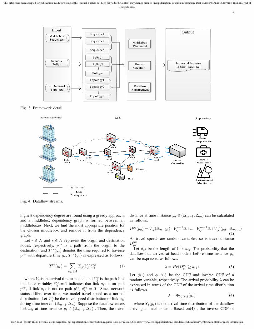
To solve the above problems, the proposed model is basedon network topologies, policy requirements, and related mid-dleboxes. First, routes are selected based on the securitypolicies, and effective middlebox deployment positions oneach route are selected. Next, the amount of traffic on eachline is limited, such that the traffic does not exceed switch andmiddleboxes capacities. Finally, SwitchTunnel is selected ac-cording to network size, for each physical sequence PhSeqc,qadd ProcState to a packet header. The next step is determinedaccording to the labels. The model framework is shown inFigure 3.
The dataflow streams of the entire IoT network are shown inFigure 4, In M-G middleboxes are connected to SDN switches.The controller route dataflow streams in SDN switches usingOpenFlow(blue dotted lines in Figure 4). The most appropriatemiddlebox position is selected by the controller using a place-ment selection algorithm. We use an ILP pruning algorithmto control the volume of traffic in each route, and use an LPformulation to balance loads across middleboxes.
Admi n
FW IDS ProxySecure
Policy
Middlebox Placement Route Selection
Dataflow Management
Topology PolicychainMbox,Switch
constraints
Port Tag Tunnel
Dataflow Management
protocol
Inadd. Nextadd. Nextport
FWIDS
Proxy
SDN
Switch
SDN
Switch
SDN
Switch
SDN
Switch
SDN
Switch
SDN
Switch
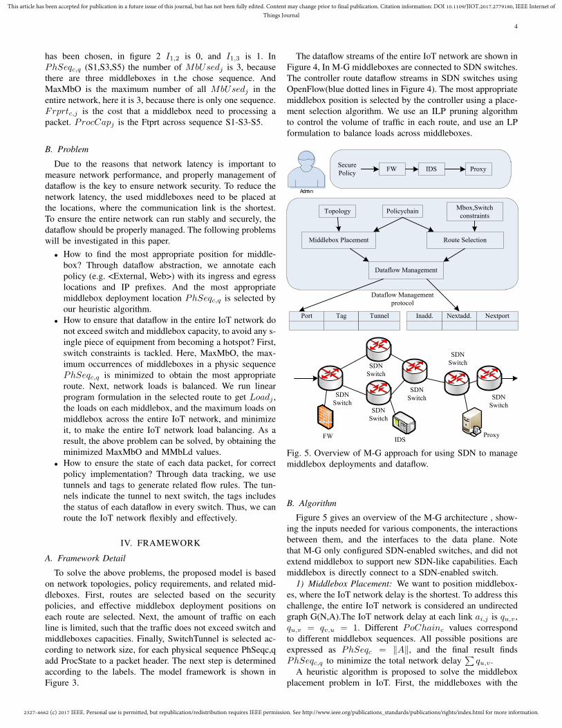
Fig. 5. Overview of M-G approach for using SDN to managemiddlebox deployments and dataflow.
B. Algorithm
Figure 5 gives an overview of the M-G architecture , show-ing the inputs needed for various components, the interactionsbetween them, and the interfaces to the data plane. Notethat M-G only configured SDN-enabled switches, and did notextend middlebox to support new SDN-like capabilities. Eachmiddlebox is directly connect to a SDN-enabled switch.
1) Middlebox Placement: We want to position middlebox-es, where the IoT network delay is the shortest. To address thischallenge, the entire IoT network is considered an undirectedgraph G(N,A).The IoT network delay at each link ai,j is qu,v ,qu,v = qv,u = 1. Different PoChainc values correspondto different middlebox sequences. All possible positions areexpressed as PhSeqc = ∥A∥, and the final result findsPhSeqc,q to minimize the total network delay
∑qu,v .
A heuristic algorithm is proposed to solve the middleboxplacement problem in IoT. First, the middleboxes with the
2327-4662 (c) 2017 IEEE. Personal use is permitted, but republication/redistribution requires IEEE permission. See http://www.ieee.org/publications_standards/publications/rights/index.html for more information.
This article has been accepted for publication in a future issue of this journal, but has not been fully edited. Content may change prior to final publication. Citation information: DOI 10.1109/JIOT.2017.2779180, IEEE Internet ofThings Journal
5
Fig. 3. Framework detail
Fig. 4. Dataflow streams.
highest dependency degree are found using a greedy approach,and a middlebox dependency graph is formed between allmiddleboxes. Next, we find the most appropriate position forthe chosen middlebox and remove it from the dependencygraph.
Let r ∈ N and s ∈ N represent the origin and destinationnodes, respectively. prs is a path from the origin to thedestination, and T rs(yr) denotes the time required to traverseprs with departure time yr. T rs(yr) is expressed as follows.
T rs(yr) =∑
aij∈A
Tij(Yj)δrsij (1)
where Yj is the arrival time at node i, and δrsij is the path-linkincidence variable; δrsij = 1 indicates that link aij is on pathprs, if link aij is not on path prs, δrsij = 0 . Since networkstatus differs over time, we model travel speed as a normaldistribution. Let V n
ij be the travel speed distribution of link aijduring time interval (∆n−1,∆n). Suppose the dataflow enterslink aij at time instance yi ∈ (∆n−1,∆n) . Then, the travel
distance at time instance ya ∈ (∆m−1,∆m) can be calculatedas follows.
Dyi(ya) = V nij (∆n−yi)+V n+1
ij ∆+...+V m−1ij ∆+V m
ij (ya−∆m−1)(2)
As travel speeds are random variables, so is travel distanceDya
yi .Let dij be the length of link aij . The probability that the
dataflow has arrived at head node i before time instance yacan be expressed as follows.
λ = Pr(Dyayi
≥ dij) (3)
Let ϕ(·) and ϕ−1(·) be the CDF and inverse CDF of arandom variable, respectively. The arrival probability λ can beexpressed in terms of the CDF of the arrival time distributionas follows.
λ = ΦYj(yi)(ya) (4)
where Yj(yi) is the arrival time distribution of the dataflowarriving at head node i. Based on(4) , the inverse CDF of
2327-4662 (c) 2017 IEEE. Personal use is permitted, but republication/redistribution requires IEEE permission. See http://www.ieee.org/publications_standards/publications/rights/index.html for more information.
This article has been accepted for publication in a future issue of this journal, but has not been fully edited. Content may change prior to final publication. Citation information: DOI 10.1109/JIOT.2017.2779180, IEEE Internet ofThings Journal
6
the arrival time distribution at the λ confidence level can becalculated as follows.
ya = Φ−1Yj(yi)
(λ) (5)
Φ−1Yj(yi)
(λ) can be calculated by (2)-(5), thus, link traveltime can be expressed as follows.
Tij(yi) = Yj(yi)− yi (6)
The shortest path can be calculated based on the link traveltime. First a heuristic evaluation function is calculated todetermine the level for path priu as follows.
F (priu ) = E(T riu (yr)) + h(i) (7)
s.t F (prju ) = E(T rju (yr))+h(j) ≥ F (priu ) = E(T ri
u (yr))+h(i)(8)
where h(i) is the mean path travel time from node i to des-tination s. Equation(8) indicates that F (priu ) should increasemonotonically with path extension.
Let P ri = {pri1 , ..., prin } be a set of nondominated pathsfrom the origin r to node i. All nondominated paths are main-tained in a priority queue that is ordered based on F (priu ). Ineach iteration, the label priu with minimum F (priu ) is selected.An acyclic temporary path priu = priu ⊕ aij is then constructedby extending the selected path priu to each successor node∀j ∈ SCS(i). The temporary path priu is inserted to prj if priuis a DL path to prj If priu dominate paths in prj . Then thesedominated paths are removed. This iteration continues untilthe destination is reached or the queue becomes empty.
Algorithm 1 PLACEMENT SELECTION ALGORITHMInput: original and destination nodes and departure time yr ;Output: The least expected time path
Step1 InitializationCreate a path prru from original to itselfSet arrival time distribution Yr(yr) = 0 for the path prruCalculate h(r) and F (prru )Set P rr = {prru } and SE = {prru }
Step2 Path selectionIf SE = φ,stop; otherwise, continueSelect priu at the top of SE and remove priu from SEIf i = s, stop ;otherwise, continue
Step3 Path extensionFor every successor node j ∈ SCS(i)If j /∈ priu ,continue; otherwise, scan next successor nodeConstruct a temporary path prju = priu ⊕ aijGenerate arrival time distribution Yj(yr) for the temporary path priuCalculate h(j) and F (priu )If prju is a nondominated path, then insert it into P rj and SE andremove all paths dominated by prju from P rj and SE
The placement selection algorithm, first calculates F (prju )based on the time required to traverse each path. Then allpaths ordered by F (prju ) are put into a priority queue. Thepath with minimum F (prju ) is selected, in each iteration, Anacyclic temporary path prju is then constructed by extendingthe selected path to each successor node SCS(i). If priu is anondominated path, it is inserted into pri. If priu FSD dominateany path in prju , the dominated paths are deleted from prj .Thealgorithm continues until the destination is reached or thequeue becomes empty. The time complexity of this algorithmis O(n ∗m).
2) Route Selection: After deploying middleboxes, two con-straints exist. One is the cost to process dataflow streamsin IoT, such as the mandatory use of the CPU, RAM andcounter. The other is the volumn restrictions in SDN switches.To address these challenges, First, an offline Integer LinearProgram(ILP) pruning algorithm is proposed to tackle theswitch constraints. Then an online Linear Program formulationis proposed to deal with load balancing.
After the middlebox is deployed, we need to select theroute which can minimize the network load. A binary indicatorvariable Ic,q is used to indicate whether a particular sequencehas been selected. To ensure that each logical chain hasa related physical sequence, a target coverage level Cov isdefined as follows. ∑
q
Ic,q ≥ Cov (9)
Ic,q ∈ {0, 1} (10)
Then, the loads on each switch are determined to ensurethat loads do not exceed switch constraints TCAM.∑
Sk∈PhSeqc,q
Rulesk,c,q × Ic,q ≤ TCAMk (11)
To ensure that no middlebox becomes a hot-spot, thenumber of middleboxes in the selected sequences is calculatedusing Linear Program pruning algorithm.
MbUsedj =∑
Mj∈PhSeqc,q
Ic,q (12)
Then find the maximum occurrences.
MaxMbO = max(MbUsedj) (13)
Finally minimize the maximum number.
MaxMbO ≥ MbUsedj (14)
Algorithm 2 ILP PATH SELECTION ALGORITHMInput: PoChainc
Output: Improved security networkInitialization:Cov, TCAM, SIc,q , Srules, MbUsed, MaxMbO;for each PoChainc do
all possible physical chains are PhSeqc;end forfor PhSeqc,q ∈ PhSeqc do
if this PhSeqc,qischoosed thenIc,q = 1;apply Rulesk,c,q ;
else {Ic,q = 0}SIc,q+ = Ic,q ;
end ifif Sk ∈ PhSeqc, q then
Srules+ = Rulesk,c,q ∗ Ic,q ;end ifif Mj ∈ PhSeqc,q then
MbUsed+ = Ic,q ;MaxMbO = max(MbUsed);
end ifend forObtain:
SIc,q ≥ Cov
2327-4662 (c) 2017 IEEE. Personal use is permitted, but republication/redistribution requires IEEE permission. See http://www.ieee.org/publications_standards/publications/rights/index.html for more information.
This article has been accepted for publication in a future issue of this journal, but has not been fully edited. Content may change prior to final publication. Citation information: DOI 10.1109/JIOT.2017.2779180, IEEE Internet ofThings Journal
7
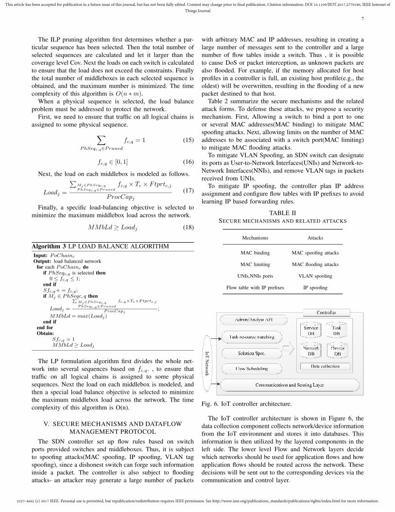
The ILP pruning algorithm first determines whether a par-ticular sequence has been selected. Then the total number ofselected sequences are calculated and let it larger than thecoverage level Cov. Next the loads on each switch is calculatedto ensure that the load does not exceed the constraints. Finallythe total number of middleboxes in each selected sequence isobtained, and the maximum number is minimized. The timecomplexity of this algorithm is O(n ∗m).
When a physical sequence is selected, the load balanceproblem must be addressed to protect the network.
First, we need to ensure that traffic on all logical chains isassigned to some physical sequence.∑
PhSeqc,q∈Pruned
fc,q = 1 (15)
fc,q ∈ [0, 1] (16)
Next, the load on each middlebox is modeled as follows.
Loadj =
∑Mj∈PhSeqc,qPhSeqc,q∈Pruned
fc,q × Tc × Ftprtc,j
ProcCapj(17)
Finally, a specific load-balancing objective is selected tominimize the maximum middlebox load across the network.
MMbLd ≥ Loadj (18)
Algorithm 3 LP LOAD BALANCE ALGORITHMInput: PoChainc
Output: load balanced networkfor each PoChainc do
if PhSeqc,q is selected then0 ≤ fc,q ≤ 1;
end ifSfc,q+ = fc,q ;if Mj ∈ PhSeqc, q then
Loadj =
∑Mj∈PhSeqc,qPhSeqc,q∈Pruned
fc,q×Tc×Ftprtc,j
ProcCapj;
MMbLd = max(Loadj)end if
end forObtain:
Sfc,q = 1MMbLd ≥ Loadj
The LP formulation algorithm first divides the whole net-work into several sequences based on fc,q. , to ensure thattraffic on all logical chains is assigned to some physicalsequences. Next the load on each middlebox is modeled, andthen a special load balance objective is selected to minimizethe maximum middlebox load across the network. The timecomplexity of this algorithm is O(n).
V. SECURE MECHANISMS AND DATAFLOWMANAGEMENT PROTOCOL
The SDN controller set up flow rules based on switchports provided switches and middleboxes. Thus, it is subjectto spoofing attacks(MAC spoofing, IP spoofing, VLAN tagspoofing), since a dishonest switch can forge such informationinside a packet. The controller is also subject to floodingattacks- an attacker may generate a large number of packets
with arbitrary MAC and IP addresses, resulting in creating alarge number of messages sent to the controller and a largenumber of flow tables inside a switch. Thus , it is possibleto cause DoS or packet interception, as unknown packets arealso flooded. For example, if the memory allocated for hostprofiles in a controller is full, an existing host profile(e.g., theoldest) will be overwritten, resulting in the flooding of a newpacket destined to that host.
Table 2 summarize the secure mechanisms and the relatedattack forms. To defense these attacks, we propose a securitymechanism. First, Allowing a switch to bind a port to oneor several MAC addresses(MAC binding) to mitigate MACspoofing attacks. Next, allowing limits on the number of MACaddresses to be associated with a switch port(MAC limiting)to mitigate MAC flooding attacks.
To mitigate VLAN Spoofing, an SDN switch can designateits ports as User-to-Network Interfaces(UNIs) and Network-to-Network Interfaces(NNIs), and remove VLAN tags in packetsreceived from UNIs.
To mitigate IP spoofing, the controller plan IP addressassignment and configure flow tables with IP prefixes to avoidlearning IP based forwarding rules.
TABLE IISECURE MECHANISMS AND RELATED ATTACKS
Mechanisms Attacks
MAC binding MAC spoofing attacks
MAC limiting MAC flooding attacks
UNIs,NNIs ports VLAN spoofing
Flow table with IP prefixes IP spoofing
IoT
Netw
ork
Fig. 6. IoT controller architecture.
The IoT controller architecture is shown in Figure 6, thedata collection component collects network/device informationfrom the IoT environment and stores it into databases. Thisinformation is then utilized by the layered components in theleft side. The lower level Flow and Network layers decidewhich networks should be used for application flows and howapplication flows should be routed across the network. Thesedecisions will be sent out to the corresponding devices via thecommunication and control layer.
2327-4662 (c) 2017 IEEE. Personal use is permitted, but republication/redistribution requires IEEE permission. See http://www.ieee.org/publications_standards/publications/rights/index.html for more information.
This article has been accepted for publication in a future issue of this journal, but has not been fully edited. Content may change prior to final publication. Citation information: DOI 10.1109/JIOT.2017.2779180, IEEE Internet ofThings Journal
8
Phase1:Intialization
Parameter:{tag}
step1
step2
step1
step2
Fig. 7. Three stages of proposed protocol.
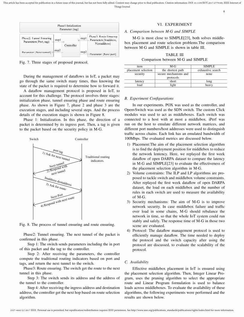
During the management of dataflows in IoT, a packet maygo through the same switch many times, thus knowing thestate of the packet is required to determine how to forward it.
A dataflow management protocol is proposed in IoT, toaccount for this challenge. The protocol involves three stages:initialization phase, tunnel ensuring phase and route ensuringphase. As shown in Figure 7, phase 2 and phase 3 are theexecution stages, and including several steps. And the processdetails of the execution stages is shown in Figure 8.
Phase 1: Initialization. In this phase, the direction of apacket is determined by its ingress port. Then, a tag is givento the packet based on the security policy in M-G.
Switch Controller
port tag1) Ask for next tunnel
Next tunnel
2) Respond with
next tunnel
Inaddress destaddress3) Ask for route
Next Port
4) Respond with next route
Traditional routing
indicators.
Fig. 8. The process of tunnel ensuring and route ensuring.
Phase2: Tunnel ensuring. The next tunnel of the packet isconfirmed in this phase.
Step 1: The switch sends parameters including the in portof this packet and the tag to the controller.
Step 2: After receiving the parameters, the controllercompute the traditional routing indicators based on port andtags, and return the next tunnel to the switch.
Phase3: Route ensuring. The switch get the route to the nexttunnel in this phase.
Step 3: The switch sends its address and the address ofthe tunnel to the controller.
Step 4: After receiving the ingress address and destinationaddress, the controller get the next hop based on route selectionalgorithm.
VI. EXPERIMENT
A. Comparison between M-G and SIMPLE
M-G is most close to SIMPLE[23], both solves middle-box placement and route selection problems.The comparisonbetween M-G and SIMPLE is shown in table III.
TABLE IIIComparison between M-G and SIMPLE
item M-G SIMPLEplacement selection the shortest path exhaustive search
security secure mechanisms andprotocols
none
latency short longload light heavy
B. Experiment Configurations
In our experiments. POX was used as the controller, andOpenvSwitch was used as the SDN switch. The custom Clickmodules was used to act as middleboxes. Each switch wasconnected to a host with at most a middlebox. iPerf wasrun on the host to emulate different network matrices, anddifferent port numbers/host addresses were used to distinguishtraffic across chains. Each link has an emulated bandwidth of100Mbps. The evaluated metrics are discussed below.
1) Placement:The aim of the placement selection algorithmis to find the deployment position for middlebox to reducethe network lentency. Here, we replayed the first weekdataflow of open DARPA dataset to compare the latencyin M-G and SIMPLE[23] to evaluate the effectiveness ofthe placement selection algorithm in M-G.
2) Volume constraints: The ILP and LP algorithms are pro-posed to tackle switch and middlebox volume constraints.After replayed the first week dataflow of open DARPAdataset, the load on each middlebox and the number ofrules in each switch are used to measure the availabilityof M-G.
3) Security mechanisms: The aim of M-G is to improvenetwork security. In case middlebox failure and trafficover load in some chains, M-G should rebalance thenetwork in time, so that the whole IoT system could runstably and safely. The response time of M-G in those twoscene are evaluated.
4) Protocol: The dataflow management protocol is used toefficiently manage dataflow. The time needed to deploythe protocol and the switch capacity after using theprotocol are discussed, to evaluate the scalability of theprotocol.
C. Availability
Effective middlebox placement in IoT is ensured usingthe placement selection algorithm. Then, Integer Linear Pro-gram, uses the pruning algorithm to select the appropriateroute and Linear Program formulation is used to balanceloads across middleboxes. To evaluate the availability of thesealgorithms, the following experiments were performed and theresults are shown below.
2327-4662 (c) 2017 IEEE. Personal use is permitted, but republication/redistribution requires IEEE permission. See http://www.ieee.org/publications_standards/publications/rights/index.html for more information.
This article has been accepted for publication in a future issue of this journal, but has not been fully edited. Content may change prior to final publication. Citation information: DOI 10.1109/JIOT.2017.2779180, IEEE Internet ofThings Journal
9
0 20 40 60 80 100 120 140 160 180 2000.0
0.1
0.2
0.3
0.4
0.5
0.6
0.7
0.8
0.9
1.0CDF
Latency(ms)
placement selection algorithm
random placement
Fig. 9. Delay distribution of all flows.
0 1 2 3 4 5 6 7 8 90
100
200
300
400
500
600
Lat
ency
(ms)
Number of middleboxes
M-G
SIMPLE
Fig. 10. Latency with different number of middlebox.
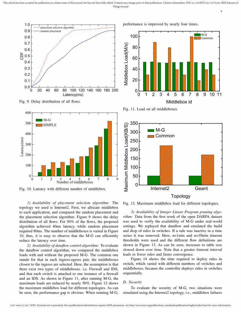
1) Availability of placement selection algorithm: Thetopology we used is Internet2. First, we allocate middleboxto each application, and compared the random placement andthe placement selection algorithm. Figure 9 shows the delaydistribution of all flows. For 50% of the flows, the proposedalgorithm achieved 40ms latency, while random placementrequired 80ms. The number of middleboxes is varied in Figure10, thus, it is easy to observe that the M-G can efficientlyreduce the latency over time.
2) Availability of dataflow control algorithm: To evaluatethe dataflow control algorithm, we compared the middleboxloads with and without the proposed M-G. The common onestands for that in each ingress-egress pair, the middleboxesclosest to the ingress are selected. Here, the assumption is thatthere exist two types of middleboxes. i.e. Firewall and IDS,and that each switch is attached to one instance of a firewalland an IDS. As shown in Figure 11, after running M-G, themaximum loads are reduced by nearly 50%. Figure 12 showsthe maximum middlebox load for different topologies. As canbe seen, the performance gap is obvious. When running M-G,
performance is improved by nearly four times.
0 1 2 3 4 5 6 7 8 9 10 110
20
40
60
80
100
Mid
dle
bo
x L
oa
d(M
/s)
Middlebox id
M-G
Common
Fig. 11. Load on all middleboxes.
Internet2 Geant0
50
100
150
200
250
300
350M
axim
um
Mid
dle
box L
oa
d(K
B/S
)
Topology
M-G
Common
Fig. 12. Maximum middlebox load for different topologies.
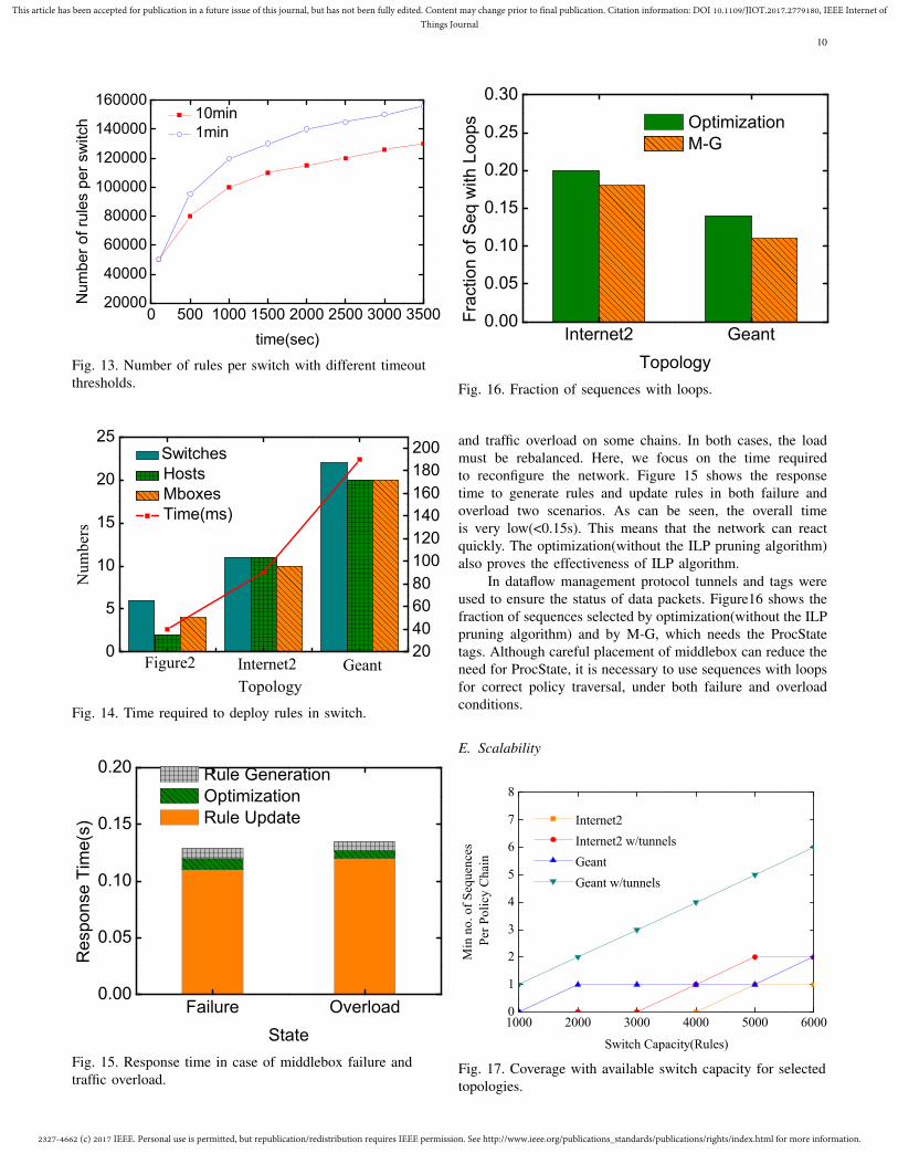
3) Availability of Integer Linear Program pruning algo-rithm: Data from the first week of the open DARPA datasetwas used to verify the availability of M-G under real-worldsettings. We replayed that dataflow and emulated the buildand drop of rules in switches. If a rule was inactive in a timeseries it was removed. Here, n=1min and n=10min timeoutthresholds were used and the different flow definitions areshown in Figure 13. As can be seen, increases to table sizeslowed down over time. Note that a greater timeout intervalleads to fewer rules and faster convergence.
Figure 14 shows the time required to deploy rules inswitch, which varied with different numbers of switches andmiddleboxes, because the controller deploys rules in switchessequentially.
D. SecurityTo evaluate the security of M-G, two situations were
simulated using the Internet2 topology, i.e., middlebox failures
2327-4662 (c) 2017 IEEE. Personal use is permitted, but republication/redistribution requires IEEE permission. See http://www.ieee.org/publications_standards/publications/rights/index.html for more information.
This article has been accepted for publication in a future issue of this journal, but has not been fully edited. Content may change prior to final publication. Citation information: DOI 10.1109/JIOT.2017.2779180, IEEE Internet ofThings Journal
10
0 500 1000 1500 2000 2500 3000 350020000
40000
60000
80000
100000
120000
140000
160000N
um
ber
of ru
les p
er
sw
itch
time(sec)
10min
1min
Fig. 13. Number of rules per switch with different timeoutthresholds.
0
5
10
15
20
25
Numbers
Topology
Switches
Hosts
Mboxes
Time(ms)
Figure2 Internet2 Geant20
40
60
80
100
120
140
160
180
200
Fig. 14. Time required to deploy rules in switch.
Failure Overload0.00
0.05
0.10
0.15
0.20
Re
sp
on
se
Tim
e(s
)
State
Rule Generation
Optimization
Rule Update
Fig. 15. Response time in case of middlebox failure andtraffic overload.
Internet2 Geant0.00
0.05
0.10
0.15
0.20
0.25
0.30
Fra
ction
of S
eq w
ith
Loops
Topology
Optimization
M-G
Fig. 16. Fraction of sequences with loops.
and traffic overload on some chains. In both cases, the loadmust be rebalanced. Here, we focus on the time requiredto reconfigure the network. Figure 15 shows the responsetime to generate rules and update rules in both failure andoverload two scenarios. As can be seen, the overall timeis very low(<0.15s). This means that the network can reactquickly. The optimization(without the ILP pruning algorithm)also proves the effectiveness of ILP algorithm.
In dataflow management protocol tunnels and tags wereused to ensure the status of data packets. Figure16 shows thefraction of sequences selected by optimization(without the ILPpruning algorithm) and by M-G, which needs the ProcStatetags. Although careful placement of middlebox can reduce theneed for ProcState, it is necessary to use sequences with loopsfor correct policy traversal, under both failure and overloadconditions.
E. Scalability
1000 2000 3000 4000 5000 60000
1
2
3
4
5
6
7
8
Min
no
. o
f S
equ
ence
s
Per
Po
licy
Ch
ain
Switch Capacity(Rules)
Internet2
Internet2 w/tunnels
Geant
Geant w/tunnels
Fig. 17. Coverage with available switch capacity for selectedtopologies.
2327-4662 (c) 2017 IEEE. Personal use is permitted, but republication/redistribution requires IEEE permission. See http://www.ieee.org/publications_standards/publications/rights/index.html for more information.
This article has been accepted for publication in a future issue of this journal, but has not been fully edited. Content may change prior to final publication. Citation information: DOI 10.1109/JIOT.2017.2779180, IEEE Internet ofThings Journal
11
Internet2 Geant-0.5
0.0
0.5
1.0
1.5
2.0
2.5T
ime t
o g
en
era
te lo
ad
ba
lance
d
co
nfig
ura
tio
ns(s
)
Topology
Opt
Opt w/tunnel
M-G
M-G w/tunnel
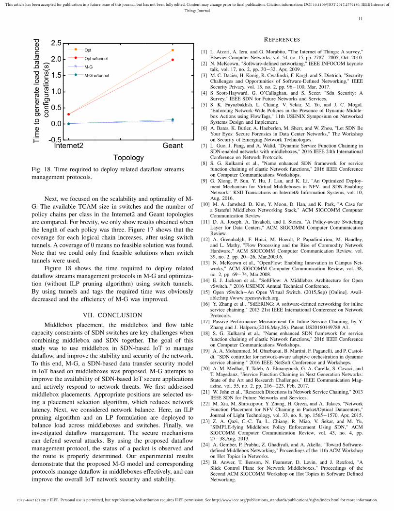
Fig. 18. Time required to deploy related dataflow streamsmanagement protocols.
Next, we focused on the scalability and optimality of M-G. The available TCAM size in switches and the number ofpolicy chains per class in the Internet2 and Geant topologiesare compared. For brevity, we only show results obtained whenthe length of each policy was three. Figure 17 shows that thecoverage for each logical chain increases, after using switchtunnels. A coverage of 0 means no feasible solution was found.Note that we could only find feasible solutions when switchtunnels were used.
Figure 18 shows the time required to deploy relateddataflow streams management protocols in M-G and optimiza-tion (without ILP pruning algorithm) using switch tunnels.By using tunnels and tags the required time was obviouslydecreased and the efficiency of M-G was improved.
VII. CONCLUSION
Middlebox placement, the middlebox and flow tablecapacity constraints of SDN switches are key challenges whencombining middlebox and SDN together. The goal of thisstudy was to use middlebox in SDN-based IoT to managedataflow, and improve the stability and security of the network.To this end, M-G, a SDN-based data transfer security modelin IoT based on middleboxes was proposed. M-G attempts toimprove the availability of SDN-based IoT secure applicationsand actively respond to network threats. We first addressedmiddlebox placements. Appropriate positions are selected us-ing a placement selection algorithm, which reduces networklatency. Next, we considered network balance. Here, an ILPpruning algorithm and an LP formulation are deployed tobalance load across middleboxes and switches. Finally, weinvestigated dataflow management. The secure mechanismscan defend several attacks. By using the proposed dataflowmanagement protocol, the status of a packet is observed andthe route is properly determined. Our experimental resultsdemonstrate that the proposed M-G model and correspondingprotocols manage dataflow in middleboxes effectively, and canimprove the overall IoT network security and stability.
REFERENCES
[1] L. Atzori, A. Iera, and G. Morabito, "The Internet of Things: A survey,"Elsevier Computer Networks, vol. 54, no. 15, pp. 2787−2805, Oct. 2010.
[2] N. McKeown, "Software-defined networking," IEEE INFOCOM keynotetalk, vol. 17, no. 2, pp. 30−32, Apr, 2009.
[3] M. C. Dacier, H. Konig, R. Cwalinski, F. Kargl, and S. Dietrich, "SecurityChallenges and Opportunities of Software-Defined Networking," IEEESecurity Privacy, vol. 15, no. 2, pp. 96−100, Mar, 2017.
[4] S Scott-Hayward, G. O’Callaghan, and S. Sezer. "Sdn Security: ASurvey," IEEE SDN for Future Networks and Services.
[5] S. K. Fayazbakhsh, L. Chiang, V. Sekar, M. Yu, and J. C. Mogul."Enforcing Network-Wide Policies in the Presence of Dynamic Middle-box Actions using FlowTags," 11th USENIX Symposium on NetworkedSystems Design and Implement.
[6] A. Bates, K. Butler, A. Haeberlen, M. Sherr, and W. Zhou, "Let SDN BeYour Eyes: Secure Forensics in Data Center Networks," The Workshopon Security of Emerging Network Technologies.
[7] L. Guo, J. Pang, and A. Walid, "Dynamic Service Function Chaining inSDN-enabled networks with middleboxes," 2016 IEEE 24th InternationalConference on Network Protocols.
[8] S. G. Kulkarni et al., "Name enhanced SDN framework for servicefunction chaining of elastic Network functions," 2016 IEEE Conferenceon Computer Communications Workshops.
[9] G. Xiong, P. Sun, Y. Hu, J. Lan, and K. Li, "An Optimized Deploy-ment Mechanism for Virtual Middleboxes in NFV- and SDN-EnablingNetwork," KSII Transactions on Internet& Information Systems, vol. 10,Aug, 2016.
[10] M. A. Jamshed, D. Kim, Y. Moon, D. Han, and K. Park, "A Case fora Stateful Middlebox Networking Stack," ACM SIGCOMM ComputerCommunication Review.
[11] D. A. Joseph, A. Tavakoli, and I. Stoica, "A Policy-aware SwitchingLayer for Data Centers," ACM SIGCOMM Computer CommunicationReview.
[12] A. Greenhalgh, F. Huici, M. Hoerdt, P. Papadimitriou, M. Handley,and L. Mathy, "Flow Processing and the Rise of Commodity NetworkHardware," ACM SIGCOMM Computer Communication Review, vol.39, no. 2, pp. 20−26, Mar,2009.6.
[13] N. McKeown et al., "OpenFlow: Enabling Innovation in Campus Net-works," ACM SIGCOMM Computer Communication Review, vol. 38,no. 2, pp. 69−74, Mar,2008.
[14] E. J. Jackson et al., "SoftFlow: A Middlebox Architecture for OpenvSwitch.," 2016 USENIX Annual Technical Conference.
[15] Open vSwitch−An Open Virtual Switch. (2015,Sep) [Online]. Avail-able:http://www.openvswitch.org.
[16] Y. Zhang et al., "StEERING: A software-defined networking for inlineservice chaining," 2013 21st IEEE International Conference on NetworkProtocols.
[17] Passive Performance Measurement for Inline Service Chaining, by Y.Zhang and J. Halpern,(2016,May,26). Patent US20160149788 A1.
[18] S. G. Kulkarni et al., "Name enhanced SDN framework for servicefunction chaining of elastic Network functions," 2016 IEEE Conferenceon Computer Communications Workshops.
[19] A. A. Mohammed, M. Gharbaoui, B. Martini, F. Paganelli, and P. Castol-di, "SDN controller for network-aware adaptive orchestration in dynamicservice chaining," 2016 IEEE NetSoft Conference and Workshops.
[20] A. M. Medhat, T. Taleb, A. Elmangoush, G. A. Carella, S. Covaci, andT. Magedanz, "Service Function Chaining in Next Generation Networks:State of the Art and Research Challenges," IEEE Communication Mag-azine, vol. 55, no. 2, pp. 216−223, Feb, 2017.
[21] W. John et al., "Research Directions in Network Service Chaining," 2013IEEE SDN for Future Networks and Services.
[22] M. Xia, M. Shirazipour, Y. Zhang, H. Green, and A. Takacs, "NetworkFunction Placement for NFV Chaining in Packet/Optical Datacenters,"Journal of Light Technology, vol. 33, no. 8, pp. 1565−1570, Apr, 2015.
[23] Z. A. Qazi, C.-C. Tu, L. Chiang, R. Miao, V. Sekar, and M. Yu,"SIMPLE-fying Middlebox Policy Enforcement Using SDN," ACMSIGCOMM Computer Communication Review, vol. 43, no. 4, pp.27−38,Aug, 2013.
[24] A. Gember, P. Prabhu, Z. Ghadiyali, and A. Akella, "Toward Software-defined Middlebox Networking," Proceedings of the 11th ACM Workshopon Hot Topics in Networks.
[25] B. Anwer, T. Benson, N. Feamster, D. Levin, and J. Rexford, "ASlick Control Plane for Network Middleboxes," Proceedings of theSecond ACM SIGCOMM Workshop on Hot Topics in Software DefinedNetworking.
2327-4662 (c) 2017 IEEE. Personal use is permitted, but republication/redistribution requires IEEE permission. See http://www.ieee.org/publications_standards/publications/rights/index.html for more information.
This article has been accepted for publication in a future issue of this journal, but has not been fully edited. Content may change prior to final publication. Citation information: DOI 10.1109/JIOT.2017.2779180, IEEE Internet ofThings Journal
12
[26] S. Shin and G. Gu, "CloudWatcher: Network security monitoring usingOpenFlow in dynamic cloud networks (or: How to provide securitymonitoring as a service in clouds?)," 2012 20th IEEE InternationalConference on Network Protocols.
[27] M. Allamanis, S. Scellato, and C. Mascolo, "Evolution of a Location-based Online Social Network: Analysis and Models," Proceedings of the2012 Internet Measurement Conference.
[28] Hu, W. Han, G.-J. Ahn, and Z. Zhao, "FLOWGUARD: Building RobustFirewalls for Software-defined Networks," Proceedings of the ThirdWorkshop on Hot Topics in Software Defined Networking.
[29] M. Honda, Y. Nishida, C. Raiciu, A. Greenhalgh, M. Handley, andH. Tokuda, "Is It Still Possible to Extend TCP?," Proc 2011 ACMSIGCOMM Conference on Internet Measurement Conference.
[30] R. Craven, R. Beverly, and M. Allman, "A Middlebox-cooperative TCPfor a Non End-to-end Internet," ACM SIGCOMM Computer Communi-cation Rev, vol. 44, no. 4, pp. 151−162, Aug,2014.
[31] K. R. Khan, Z. Ahmed, S. Ahmed, A. Syed, and S. A. Khayam, "Rapidand Scalable Isp Service Delivery Through a Programmable Middlebox,"ACM SIGCOMM Computer Communication Review, vol. 44, no. 3, pp.31−37, Jul,2014.
[32] F. Qian, V. Gopalakrishnan, E. Halepovic, S. Sen, and O. S-patscheck,"TM3:flexible transport-layer multi-pipe multiplexing middle-box without head-of-line blocking[C]". Proceedings of the 11th ACMConference on Emerging Network Experiments and Technologies.
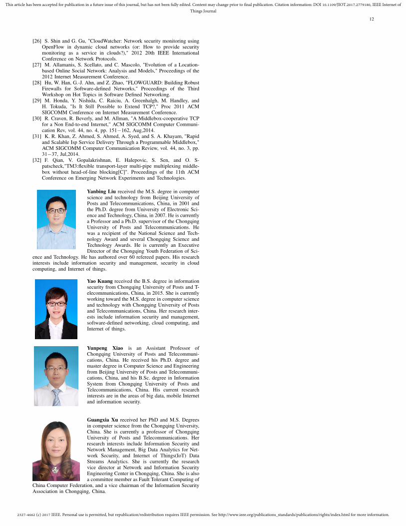
Yanbing Liu received the M.S. degree in computerscience and technology from Beijing University ofPosts and Telecommunications, China, in 2001 andthe Ph.D. degree from University of Electronic Sci-ence and Technology, China, in 2007. He is currentlya Professor and a Ph.D. supervisor of the ChongqingUniversity of Posts and Telecommunications. Hewas a recipient of the National Science and Tech-nology Award and several Chongqing Science andTechnology Awards. He is currently an ExecutiveDirector of the Chongqing Youth Federation of Sci-
ence and Technology. He has authored over 60 refereed papers. His researchinterests include information security and management, security in cloudcomputing, and Internet of things.
Yao Kuang received the B.S. degree in informationsecurity from Chongqing University of Posts and T-elecommunications, China, in 2015. She is currentlyworking toward the M.S. degree in computer scienceand technology with Chongqing University of Postsand Telecommunications, China. Her research inter-ests include information security and management,software-defined networking, cloud computing, andInternet of things.
Yunpeng Xiao is an Assistant Professor ofChongqing University of Posts and Telecommuni-cations, China. He received his Ph.D. degree andmaster degree in Computer Science and Engineeringfrom Beijing University of Posts and Telecommuni-cations, China, and his B.Sc. degree in InformationSystem from Chongqing University of Posts andTelecommunications, China. His current researchinterests are in the areas of big data, mobile Internetand information security.
Guangxia Xu received her PhD and M.S. Degreesin computer science from the Chongqing University,China. She is currently a professor of ChongqingUniversity of Posts and Telecommunications. Herresearch interests include Information Security andNetwork Management, Big Data Analytics for Net-work Security, and Internet of Things(IoT) DataStreams Analytics. She is currently the researchvice director at Network and Information SecurityEngineering Center in Chongqing, China. She is alsoa committee member as Fault Tolerant Computing of
China Computer Federation, and a vice chairman of the Information SecurityAssociation in Chongqing, China.