Embed Size (px)
Citation preview
SE 555 Software Requirements & Specification
Requirements Analysis
SE 555 Software Requirements & Specification
Goals of Requirements Analysis
Create requirements containing sufficient detail and of high enough quality to allow realistic project planning as well as successful design and implementation.
Scrutinize requirements for errors, conflicts, omissions and boundaries.
SE 555 Software Requirements & Specification
Requirements Analysis Practices
Analyze feasibility Allocate requirements to subsystems Create prototypes where necessary Model the requirements Prioritize the requirements Define system boundaries and interfaces Create consistent data definitions
SE 555 Software Requirements & Specification
Requirements Analysis Checklist
Premature Design – Does the requirement include premature design or implementation information?
Combined Requirements – Does the description of a requirement describe a single requirement or could it be broken down into several different requirements?
Unnecessary Requirements – Is the requirement “gold plating”? That is, is the requirement a cosmetic addition to the system which is not really necessary.
Use of Non-standard Components – Does the requirement mean that non-standard hardware or software must be used?
SE 555 Software Requirements & Specification
Requirements Analysis Checklist – cont’d
Conformance with Business Goals – Is the requirement consistent with the business goals defined in the introduction to the requirements document/
Requirements Ambiguity – Is the requirement ambiguous i.e. could it be read in different ways by different people?
Requirements Realism – Is the requirement realistic given the technology which will be used to implement the system?
Requirements Testability – Is the requirement testable? Is it stated in such a way that a test can be derived to show if the system meets the requirement?
SE 555 Software Requirements & Specification
Requirements Analysis Artifacts
System Boundaries – Context Diagram Requirements Modeling – Class Diagrams, Activity State
Diagrams, Interaction Diagrams, Sequence Diagrams, Data Flow Diagrams, Entity-Relationship Diagrams
Data Definition – Data Dictionary Requirements Priority – Prioritization Matrix Requirements Definition, Risk Mitigation, Feasibility –
Prototypes
SE 555 Software Requirements & Specification
Context Diagram - Purpose
Highlights the boundary between the system and the outside world.
Highlights the people, organizations, and outside systems that interact with the system under development.
Special case of the data flow diagram.
SE 555 Software Requirements & Specification
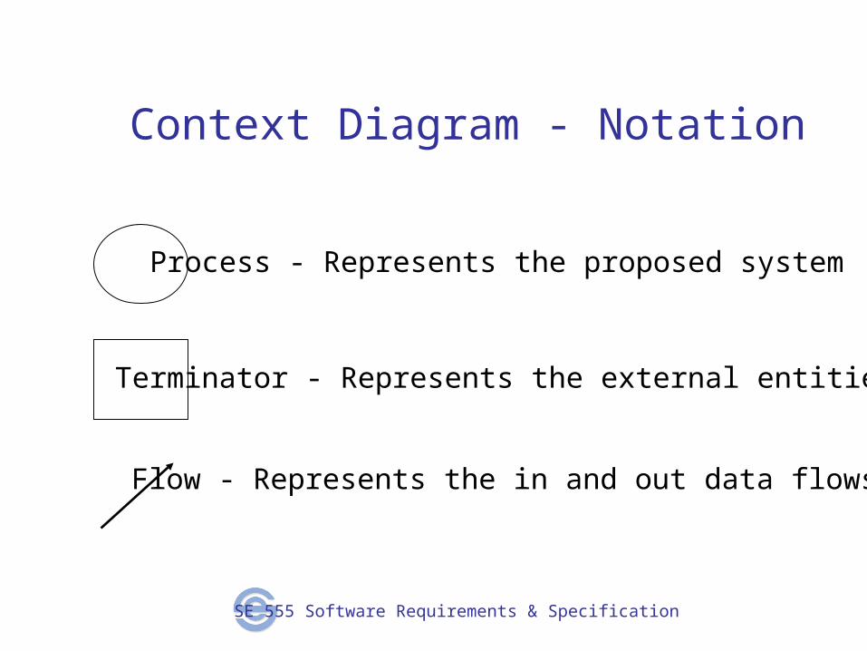
Context Diagram - Notation
Process - Represents the proposed system
Terminator - Represents the external entities
Flow - Represents the in and out data flows
SE 555 Software Requirements & Specification
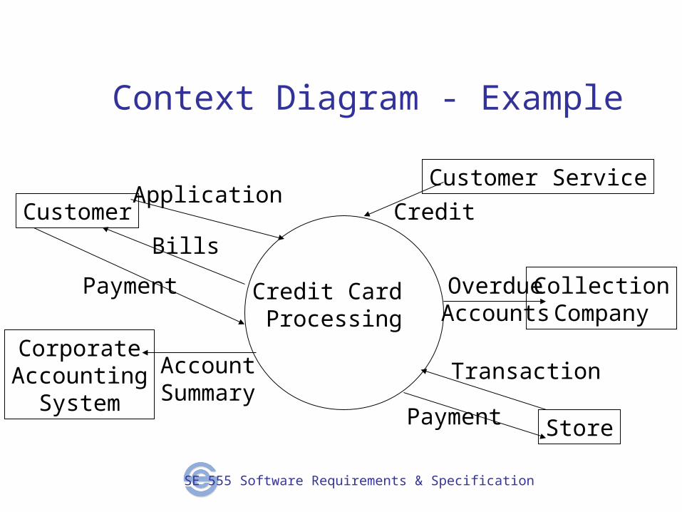
Context Diagram - Example
Credit Card Processing
Customer
CollectionCompany
CorporateAccounting
SystemStore
Customer ServiceApplication
Bills
Payment
Transaction
Payment
OverdueAccounts
Credit
AccountSummary
SE 555 Software Requirements & Specification
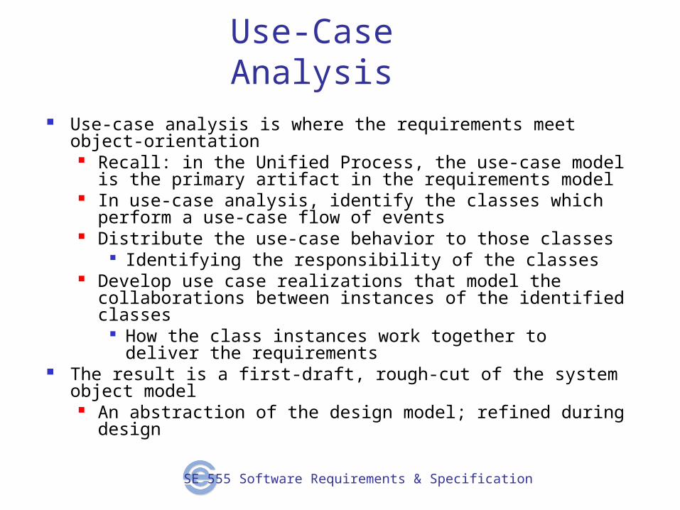
Use-Case Analysis Use-case analysis is where the requirements meet object-orientation
Recall: in the Unified Process, the use-case model is the primary artifact in the requirements model
In use-case analysis, identify the classes which perform a use-case flow of events
Distribute the use-case behavior to those classes Identifying the responsibility of the classes
Develop use case realizations that model the collaborations between instances of the identified classes
How the class instances work together to deliver the requirements
The result is a first-draft, rough-cut of the system object model An abstraction of the design model; refined during design
SE 555 Software Requirements & Specification
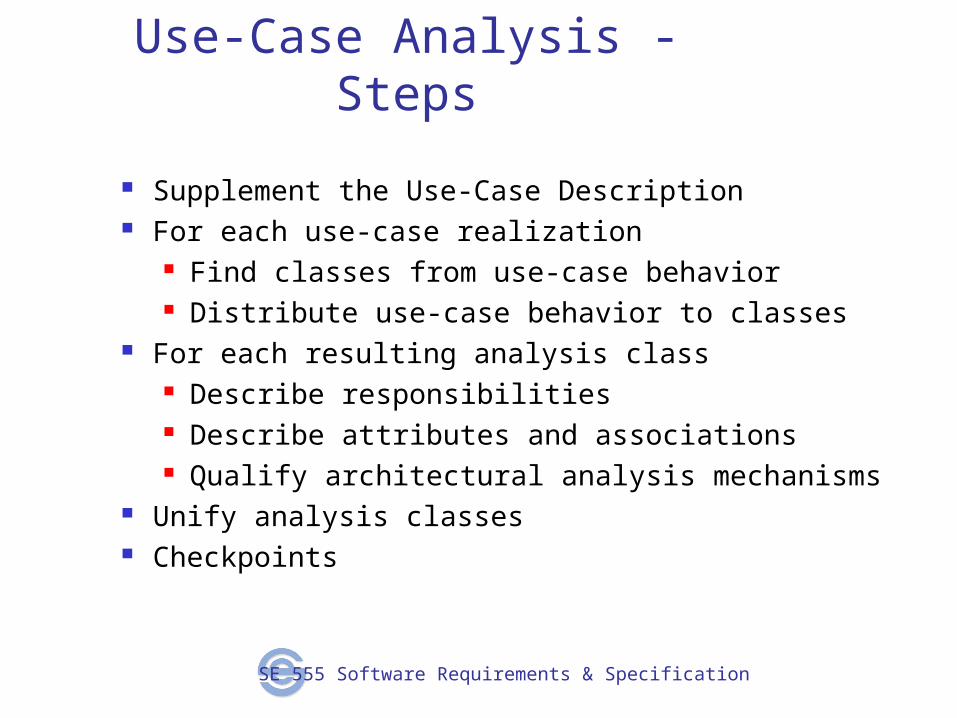
Use-Case Analysis - Steps
Supplement the Use-Case Description For each use-case realization
Find classes from use-case behavior Distribute use-case behavior to classes
For each resulting analysis class Describe responsibilities Describe attributes and associations Qualify architectural analysis mechanisms
Unify analysis classes Checkpoints
SE 555 Software Requirements & Specification
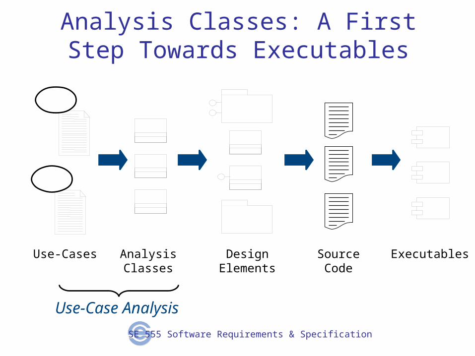
Analysis Classes: A First Step Towards Executables
Use-Cases AnalysisClasses
DesignElements
SourceCode
Executables
Use-Case Analysis

SE 555 Software Requirements & Specification
Data Flow Diagram - Purpose
Provides a means for functional decomposition. Primary tool in analysis to model data transformation in
the system.
SE 555 Software Requirements & Specification
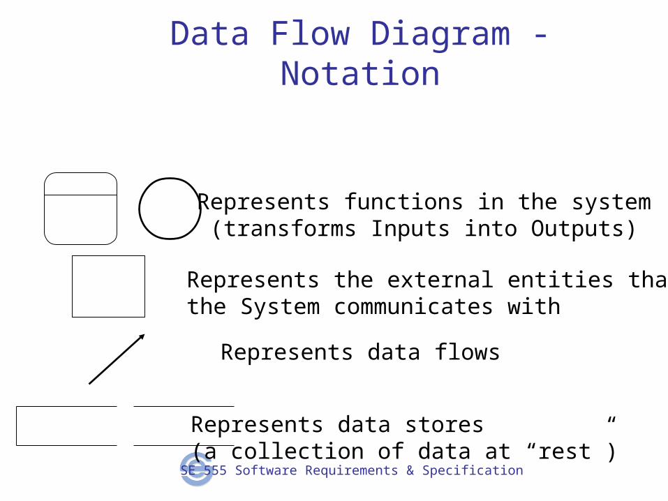
Data Flow Diagram - Notation
Represents the external entities that the System communicates with
Represents data flows
Represents functions in the system(transforms Inputs into Outputs)
Represents data stores(a collection of data at “rest”)
SE 555 Software Requirements & Specification
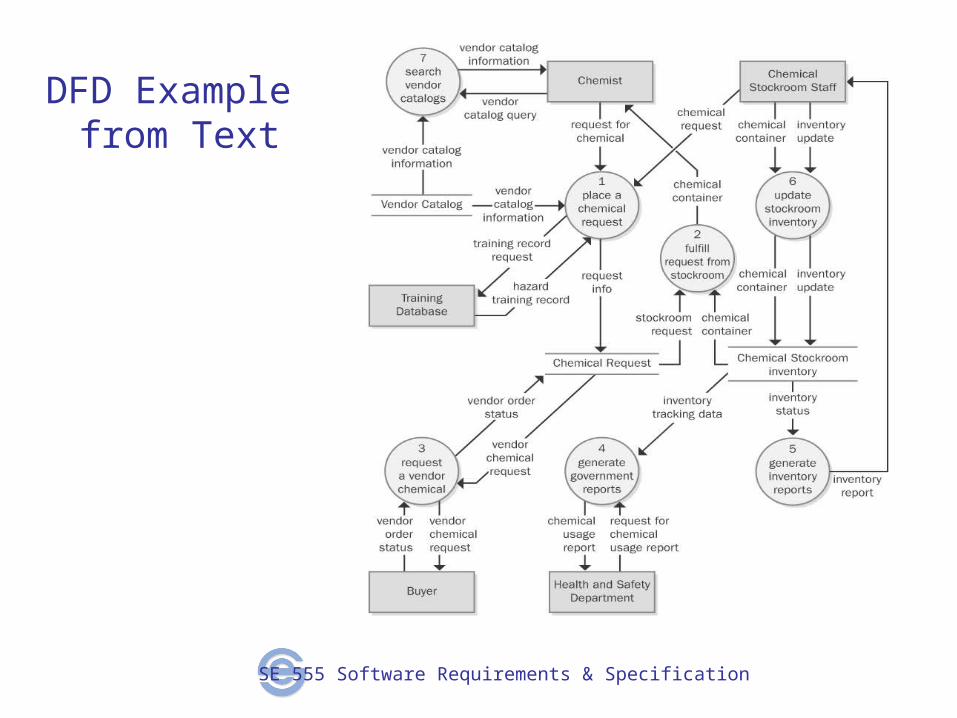
DFD Example from Text
SE 555 Software Requirements & Specification
Data Dictionary
A repository that defines the data elements or attributes used in the system
It is not the project glossary Makes it easy to find info about the data Avoids redundancy and maintenance issues, over being in
various func. req. Have it as an appendix in your SRS (project)
SE 555 Software Requirements & Specification
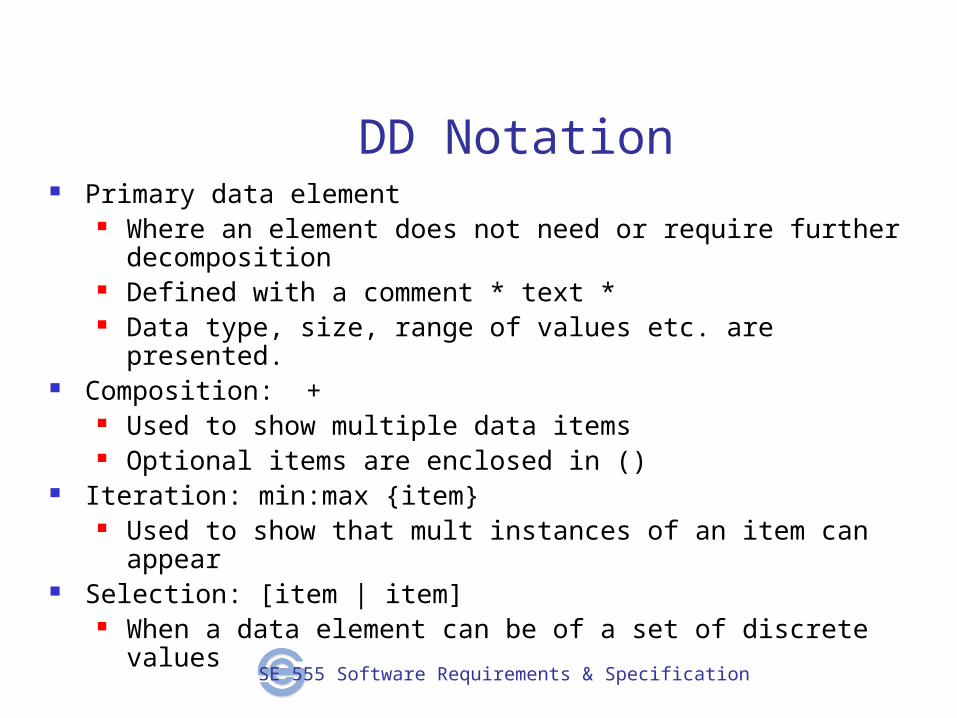
DD Notation Primary data element
Where an element does not need or require further decomposition Defined with a comment * text * Data type, size, range of values etc. are presented.
Composition: + Used to show multiple data items Optional items are enclosed in ()
Iteration: min:max {item} Used to show that mult instances of an item can appear
Selection: [item | item] When a data element can be of a set of discrete values
SE 555 Software Requirements & Specification
DD Examples Customer Name Phone Number
SE 555 Software Requirements & Specification
DD Notation
Entry comprised of: (and listed in alphabetical order) Name: its name Aliases: if it goes by another name as well Used in: the use cases it is present in, by id and name Description: the notation goes here Notes: any special notes about it
SE 555 Software Requirements & Specification
Entity Relationship Diagram (ERD) - Purpose
A graphical representation of the data layout of a system at a high level of abstraction.
Defines data elements and their inter-relationships in the system.
SE 555 Software Requirements & Specification
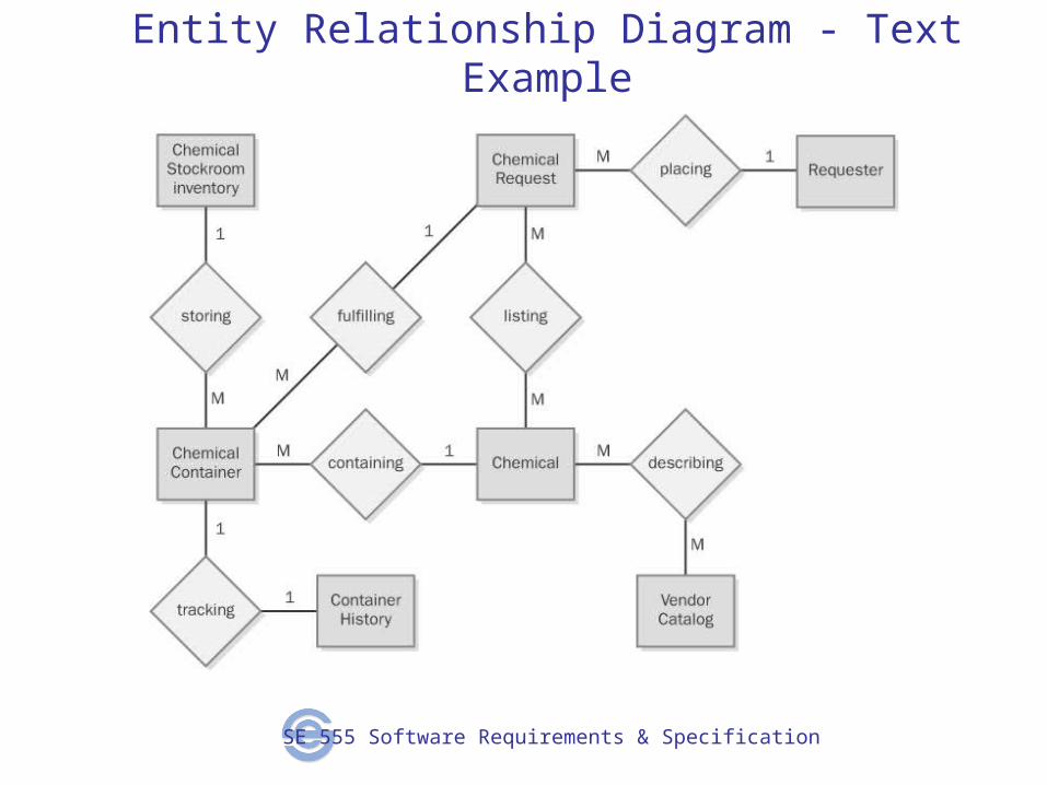
Entity Relationship Diagram - Text Example