Embed Size (px)
Citation preview

www.advenergymat.de
Full paper
1701729 (1 of 9) © 2017 WILEY-VCH Verlag GmbH & Co. KGaA, Weinheim
A 4 V Na+ Intercalation Material in a New Na-Ion Cathode Family
Se Young Kim, Dipan Kundu, and Linda F. Nazar*
DOI: 10.1002/aenm.201701729
The voltage and capacity of the posi-tive host (cathode) material is the major determinant of the specific energy. There-fore, in parallel to LIBs, a large thrust in NIB research has been in identifying and developing new cathode hosts. Many dif-ferent Na-ion analogues of classic Li-ion hosts have been explored. Distinct struc-tural and electrochemical differences have emerged that are largely attributable to the larger size of the Na+ ion.[13,14] Advances in Na-ion intercalation host materials based on oxides including NaNi1/3Mn1/3Co1/3O2, P2-Na0.67Mn0.5Fe0.5O2, and β-NaMnO2 have been realized.[12,15,16] Breakthroughs have been reported with novel poly-anionic materials such as Na1.5VPO4.8F0.7 and Na2Fe2(SO4)3.[17,18] These latter two materials exhibit a remarkably high redox potential of 3.8 V versus Na for V5+/V3.8+ and Fe3+/Fe2+ redox, respectively. In fact, compared to layered oxides, polyanionic materials often present better structural
and thermal stability, a flatter voltage response upon Na-(de)intercalation and better capacity retention.[19] In the pursuit of high capacity and high voltage cathodes, studies have focused on transition metals capable of multiple electron redox. Their redox potential can be tuned by altering the polyanionic group—for example, replacing PO4
3− with the more electron-withdrawing SO4
2− moitié raises the voltage. The latter approach has been heavily exploited for the Fe2+/Fe3+ redox couple. It has not been typically utilized for the Co2+/Co3+ or Ni2+/Ni4+ cou-ples, however, because their redox voltages already lie above the upper stability window of liquid organic electrolytes (≈ 4.3 V vs Na/Na+ with a passivated cathode). For example, the Co2+/3+ couple is close to 5 V for PO4
3-based polyanion cathodes.[19–25] As a result, low discharge capacities are exhibited (<50 mA g−1). While cobalt is not an ideal choice for the redox center for NIBs because of its high cost, this metal has been explored in combination with a variety of polyanions—including the less withdrawing [SiO4]4− moitié—in an attempt to find a compro-mise between voltage and electrolyte stability. For example, Na2CoSiO4 exhibits a high reversible capacity of 100 mA g−1, but at a moderate voltage of 3.3 V versus Na/Na+.[23] Alterna-tively, NaCo(PO3)3 and NaCoP2O7 show higher redox potentials between 3.5 and 3.7 V, but exhibit low discharge capacities of only 35 and 38 mA h g−1, respectively.[21,24] In Na4Co3(PO4)2P2O7, the Co2+/3+ redox couple is reported to be over 4.75 V (with an initial discharge capacity of ≈ 90 mA g−1) but this high redox potential induces electrolyte decomposition.[20]
Large-scale electrochemical energy storage is a critical factor in the devel-opment of renewable energy sources to enable their intermittent power to become dispatchable. In this context, Na-ion batteries are seen as promising alternatives to Li-ion batteries, but their advancement requires the discovery of new materials, their electrochemical properties, and a better understanding of structure–property relationships that underpin the electrochemistry. This study presents a new class of Na+ insertion materials for Na-ion batteries. By virtue of its moderately inductive polyanionic framework, the air and moisture stable selenite Na2Co2(SeO3)3 displays a highly suitable redox potential of ≈ 4 V versus Na/Na+ based on the Co2+/Co3+ couple, rendering it compatible with conventional liquid organic electrolytes. A microwave hydrothermal synthesis route is developed for the rapid synthesis of nanostructured Na2Co2(SeO3)3 and its conductive graphene oxide composite. The electrochemistry and structural evolution of Na2Co2(SeO3)3 determined on cycling the cathode in a Na battery was investigated by operando X-ray diffraction, X-ray photoelectron spectroscopy, and temperature dependent magnetic susceptibility measure-ments. These studies reveal good structural and electrochemical reversibility.
S. Y. Kim, Dr. D. Kundu, Prof. L. F. NazarDepartment of ChemistryUniversity of Waterloo200 University Avenue West, Waterloo, Ontario N2L3G1, CanadaE-mail: [email protected]
The ORCID identification number(s) for the author(s) of this article can be found under https://doi.org/10.1002/aenm.201701729.
Sodium-Ion Batteries
1. Introduction
The need for high performance electrochemical energy storage devices is growing overwhelmingly every year. This demand has propelled intense research efforts to build better battery systems and has revived some previously neglected chemistries such as sodium-ion batteries (NIBs).[1–3] Lithium ion batteries (LIBs) are ubiquitous in applications constrained by mass and volume, i.e., portable electronic devices and electric vehicles.[4–7] For stationary energy storage, however, earth abundant and low cost NIBs offer important sustainability and cost-effectiveness.[8–10] While sodium is heavier than lithium (which renders the cathode a slightly lower gravimetric capacity), it lends itself to different chemistries. In this regard, NIBs can be advantageous over their LIB counterparts.[11,12] Moreover, since the redox potential of sodium (−2.73 V vs the standard hydrogen electrode) is only 0.3 V higher than lithium, the energy penalty to pay is small.
Adv. Energy Mater. 2017, 1701729

www.advenergymat.dewww.advancedsciencenews.com
© 2017 WILEY-VCH Verlag GmbH & Co. KGaA, Weinheim1701729 (2 of 9)
Herein, by utilizing a rather different, intermediate electron-withdrawing polyanionic selenite group for the first time, we present a new class of cathode material—Na2Co2(SeO3)3 —which displays a highly suitable cobalt redox potential of ≈4 V versus Na/Na+ owing to Co2+/Co3+ redox. Although this voltage is by far the most moderate cobalt redox potential reported to date for sodium-based polyanionic materials, it is still one of the highest among NIB cathode hosts. Importantly, it is com-patible with the upper stability limit of typical liquid organic electrolytes. We have also developed a microwave hydrothermal synthesis route for the rapid synthesis of nanostructured Na2Co2(SeO3)3 and its graphene oxide (GO) composite. The electrochemistry and structural evolution of the Na2Co2(SeO3)3 composite - determined by cycling the cathode in a Na bat-tery - has been investigated by operando X-ray diffraction (XRD), X-ray photoelectron spectroscopy (XPS), and tempera-ture dependent magnetic susceptibility measurements. These studies reveal good structural and electrochemical reversibility.
2. Results and Discussion
2.1. Synthesis and Physiochemical Characterization
Even though transition metal selenites (SeO32− containing com-
pounds) are less prone to thermal decomposition than sulfates, they are not as stable as transition metal oxides or polyanionic compounds containing PO4
3− or SiO44− anions.[26,27] Therefore,
selenites are normally synthesized via low temperature hydro-/solvothermal routes, which require prolonged heat treatment and a mineralizer for better phase purity and crystallinity.[28–31] Here, by employing a microwave heat treatment, we achieved an ultrafast (30 min) and scalable hydrothermal approach for the synthesis of crystalline-nanosized Na2Co2(SeO3)3. Similar
to other polyanionic materials, this compound is an electrical insulator. In order to fabricate an electrically conductive com-posite material, a GO–Na2Co2(SeO3)3 composite material was also prepared by employing the microwave hydrothermal route.
The pristine material was confirmed to be Na2Co2(SeO3)3 by powder XRD. Rietveld refinement led to the fit in the Cmcm space group shown in Figure 1a, corresponding to lattice para-meters of a = 11.1449 (1), b = 7.5591 (3), and c = 10.2655 (1) Å. More information on the refinement is provided in Table S1 in the Supporting Information. A small amount of unidentified impurity was detected in the diffraction pattern (inset, Figure 1a) which was also visible under high-resolution transmission elec-tron microscopy (HRTEM) imaging (see below). The 3D open framework structure of orthorhombic Na2Co2(SeO3)3 has been previously reported (Figure 1b).[32] It consists of 2D CoSeO3 layers that are crosslinked by SeO3 units into a pillared architec-ture, leading to intersecting large channels for 2D Na+ migra-tion parallel to the a and c crystallographic axes. There are two crystallographically distinct Na sites in this structure. We note that the site occupying the channel along a is only half filled, and vacancies at the intersection of conduction pathways allow multidimensional diffusion. The Rietveld refinement of the XRD pattern of the as-synthesized Na2Co2(SeO3)3 –GO com-posite (Figure S1a, Supporting Information) is the same as that of the pristine material (Figure S1b, Supporting Information).
Thermogravimetric (TG) analyses of the pristine and the composite material (Figure S2, Supporting Information) were performed to determine that the fraction of GO in the com-posite was 15 wt%. Thermal analysis also showed that both the pristine and the composite materials are stable up to 500 °C in air, which indicates good oxidative stability that is crucial for a high voltage cathode. Scanning electron microscopy (SEM) images of the pristine and GO composite materials are shown in Figure 2a,b, respectively. The pristine material is a mixture
Adv. Energy Mater. 2017, 1701729
Figure 1. a) Rietveld refinement of the powder XRD pattern of the pristine Na2Co2(SeO3)3. The experimental data are shown in red circles, the calculated pattern is shown in black, the difference curve is shown in blue, and the Bragg positions are shown in magenta. b) Crystal structure of Na2Co2(SeO3)3 viewed along the [100] and [001] directions, showing the Na+ migration channels in a 3D open framework built by CoO6 and SeO3 polyhedra. Color code: blue, CoO6 octahedra; green, trigonal planar SeO3; red spheres, O; yellow (or yellow/white representing partial occupancy of the second Na site) spheres, Na.

www.advenergymat.dewww.advancedsciencenews.com
© 2017 WILEY-VCH Verlag GmbH & Co. KGaA, Weinheim1701729 (3 of 9)
of plate and rod-shaped particles with thicknesses ranging from 300 nm to 1 µm. These particles are composed of thin crystalline plates with a smooth surface (Figure 2a, inset). The GO composite material consists of ≈1 µm cubic particles dispersed on graphene sheets, where the cubes are also com-posed of multiple thin plates (Figure 2b, inset). Low magnifi-cation TEM images shown in the inset of Figure 2c,d further confirm the rod and cube like morphology of the pristine and the composite material, respectively. The HRTEM images pro-vide more detailed insight into the microstructure of the par-ticles (Figure 2c,d). Two perpendicular set of lattice fringes are visible—(002) and (020)—corresponding to d-spacings of 0.378 and 0.525 nm, respectively; (002) planes runs along the length and (020) planes run along the width of the crystallites. We conclude that the particles terminate at the (200) surface with the a axis as the reduced growth direction. This feature is expected to assist Na+-ion mobility since the a direction has open pathways for Na+ migration. HRTEM studies also revealed a thin layer of an unknown phase (denoted as α) on the surface of the particles. This 5 nm impurity layer, which most likely corresponds to the unidentified impurity observed in the XRD pattern, can be seen in Figure 2 c,d and Figure S3 in the Supporting Information.
The activation energy (Ea) for Na ion migration and the corre-sponding Na+ ionic conductivity were determined by performing electrochemical impedance spectroscopy (EIS) measurements on a pressed Na2Co2(SeO3) powder pellet. Figure S4 in the Sup-porting Information shows the impedance plots obtained at dif-ferent temperatures ranging from 25 to 170 °C and the Arrhe-nius plot obtained by fitting the bulk conductivity values. The ionic conductivity of 1.51 × 10⁻⁸ S cm−1 at 298 K is comparable to values for other polyanion materials such as NASICON type Na3V2(PO4)3 or cubic Na3TiP3O9N (both ≈10−7 S cm−1).[33,34]
The observed Ea of 0.6 eV atom−1 is similar to that reported for either Na3TiP3O9N or P2 type layered Na2Co2TeO6.[35] While the pristine material showed poor electrical conductivity (≈10−10 S cm−1), as do most polyanion materials,[36] the elec-trical conductivity of the Na2Co2(SeO3)–GO composite increased by nine orders of magnitude to 65 mS cm−1. This increase is key to electrochemical performance as we show below.
2.2. Structural Changes upon Electrochemical Cycling
The evolution of the diffraction pattern obtained by an operando XRD study during the first charge/discharge cycle is shown in Figure 3a (see Figure S5 in the Supporting Information for fur-ther details). A continuous shift of peak positions on cycling is evident, with the trend during Na+ extraction being reversed on reinsertion. Further analysis reveals an underlying complex pro-cess. Upon Na+ extraction beyond x ≈ 0.35 in Na2−xCo2(SeO3)3, the XRD peaks broaden and the peak intensity decreases, a trend which continues until x ≈ 0.7. This point is accompanied by a potential jump to 4.2 V in the galvanostatic profile. We ascribe the peak broadening to microstrain generation resulting from electrostatic repulsion between adjacent CoSeO3 layers that accompanies Na+ extraction. Subsequent desodiation leads to an apparent biphasic process as demonstrated by the appear-ance of new peaks at 2θ = 26.77° and 34.07°, which evolve in the XRD pattern up until x ≈ 1.6. The deintercalation limit corresponds to a composition of Na0.4Co2(SeO3)3. The chemical composition of the electrochemically charged material was also probed by energy dispersive X-ray spectroscopy (EDX) and com-pared to that of the starting phase (Figure S6a,b, Supporting Information). While EDX does not provide a rigorous quan-titative analysis, nonetheless the data show that after the first
Adv. Energy Mater. 2017, 1701729
Figure 2. SEM images of a) pristine Na2Co2(SeO3)3 and b) Na2Co2(SeO3)3–GO composite materials. HRTEM images show the lattice fringes in the c) pristine Na2Co2(SeO3)3 and d) Na2Co2(SeO3)3–GO composite crystallites indicative of a high degree of crystallinity.

www.advenergymat.dewww.advancedsciencenews.com
© 2017 WILEY-VCH Verlag GmbH & Co. KGaA, Weinheim1701729 (4 of 9)
charge, the Na content of the charged compound is ≈ 0.4 mol per formula unit (i.e., Na0.4Co2(SeO3)3). This value —80% of theoretical—is in excellent agreement with the electrochemical results. On charging above 4.4 V, the electrochemistry is domi-nated by electrolyte degradation.
Interestingly, structural evolution during discharge does not mirror charge. The biphasic-like process on discharge occurs in a smaller compositional window of 1.8 ≥ x ≥ 1.45, followed by an extended solid solution region until x ≈ 0.4. Nonetheless, following a complete cycle, the XRD pattern is very similar to the pristine pattern, suggesting good structural reversibility. It is noteworthy that during the charge/discharge process, all the peaks upshift/downshift slightly, indicating an underlying solid solution mechanism. The appearance of two new peaks (red arrows, Figure 3) suggests a two-phase reaction in the compo-sition range, but these peaks also shift continuously which is typical of a solid solution reaction.
The evolution of the lattice parameters of Na2−xCo2(SeO3)3 phases during Na+ (de)intercalation was derived from full-pat-tern matching (Figure 3b). For most of the charge process, all three lattice parameters (a, b, and c) of the orthorhombic system continuously decrease with decreasing Na content. This can be attributed to the contraction of the cobalt octahedra upon Co2+ oxidation to Co3+. However, toward the end of charge, at x > 1.3, the a and c parameters increase slightly with Na removal. This
is due to the increasing electrostatic repulsion between adjacent O2− layers that are no longer screened by Na+, because the layers are nearly empty. During discharge, increasing Na+ content leads to expansion of the lattice parameters, but again, the process follows a different trend than during charge. The lattice param-eters increase sharply at the beginning of discharge with a small change in Na+ content (a, c: until x ≤ 1.3; b: until x ≤ 1.5), beyond which they are almost constant until the end of discharge. After a full cycle, the lattice parameters return to their initial values. Typically polyanionic compounds undergo significant volume change, especially for Na+ (de)intercalation due to the large size of the Na+ cation, but Na2−xCo2(SeO3)3 (2 < x < 0.2) undergoes a relatively small volume change of ≈4.7%, which is beneficial.
The structural stability upon electrochemical cycling was investigated by ex situ XRD analysis of the charged/discharged electrodes. Figure 3c shows the ex situ XRD patterns of the as-prepared, 1st charged/discharged and 10th charged/discharged Na2Co2(SeO3)3 electrodes. The pattern of the material after the 10th cycle is very similar to that of the pristine, suggesting stability of the 3D structural framework. Closer examina-tion reveals a change in the peak intensity ratios, whereby the intensity of the (310), (331), and (117, 443) reflections increase with cycling. Electrochemical grinding upon repeated cycling, leading to morphological degradation of the cubic particles of the GO composite as evident in the SEM image of electrode
Adv. Energy Mater. 2017, 1701729
Figure 3. a) Operando XRD data of Na2Co2(SeO3)3–GO electrode (left) during the first charge/discharge cycle at C/20 (5 mA g−1) in the potential range of 1.0–4.5 V (vs Na/Na+) (left) as a function of intercalated Na+ concentration (right). b) Evolution of lattice parameters of Na2−xCo2(SeO3)3 calculated from operando X-ray diffraction patterns as a function of Na+ composition during the first cycle. c) Ex situ XRD patterns collected from as-prepared, 1st charged/discharged and 10th charged/discharged electrodes.

www.advenergymat.dewww.advancedsciencenews.com
© 2017 WILEY-VCH Verlag GmbH & Co. KGaA, Weinheim1701729 (5 of 9)
after 100 cycles (Figure S7, Supporting Information) likely explains this. Structural modification induced by cation disor-dering cannot be ruled out, however. In-depth operando and ex situ synchrotron-XRD structural studies are required to probe the subtle details of the apparent biphasic and solid solution process, which will be the topic of future work.
2.3. Electrochemical Performance
Electrochemical properties of the pristine nanostructured Na2Co2(SeO3)3 and the Na2Co2(SeO3)3–GO composites were evaluated in Na half cells. The cathode materials were utilized without further modification such as carbon coating or particle downsizing. The GO composite material exhibited better per-formance than the pristine material due to its much higher electrical conductivity, and hence only it will be discussed here (comparison with the pristine material is described in Figure S8 in the Supporting Information). Figure 4a shows the first three cyclic voltammograms of the GO composite. The cyclic voltammetry (CV) curves show two closely spaced revers-ible peaks, indicating two independent electrochemical pro-cesses. The first cycle differs a little from subsequent cycles. It shows an increasing current response at the end of the anodic sweep which primarily results from electrolyte oxidation, and
the appearance of cathodic peaks at slightly lower voltages rela-tive to those in the subsequent cycles. In subsequent cycles, the reversible anodic/cathodic peaks are centered at 4 and 4.15 V. These potentials are very “moderate” for a cobalt-based sodium polyanionic compound,[20–25] although a similar potential was reported for LiCoBO3.[37] Like trigonal BO3
3−, the trigonal SeO3
2− group (where Se4+ is the central cation) is a very weakly inductive polyanion compared to tetrahedral PO4
3− or SO44−.
The two redox peaks arise due to the de/intercalation of sodium ions from two distinct lattice sites in the crystal structure and involve the Co2+/Co3+ couple as confirmed by XPS and mag-netic property studies (see below).
Figure 4b shows the voltage-capacity profiles of the Na2Co2(SeO3)3–GO composite electrode for the first three cycles between 1.0 and 4.5 V at a C/20 rate, where 1 C corresponds to the theoretical 2e− capacity of ≈ 98 mA h g−1. After the first dis-charge, a capacity of 75 mA h g−1 is recovered. Raising the lower cutoff voltage to 1.5 V results in a lower capacity (≈ 50 mA h g−1; Figure S9, Supporting Information) owing to increased polari-zation at high Na content, and therefore the wider window was utilized in this study. The charge profile exhibits multiple plateau-like features along with sloping regions, indicating a rather complex phase evolution as demonstrated by the oper-ando XRD studies. The discharge profile primarily consists of a 4 V plateau followed by a sloping region corresponding to a
Adv. Energy Mater. 2017, 1701729
Figure 4. a) Cyclic voltammograms of the Na2Co2(SeO3)3–GO electrode during the first three cycles at a scan rate of 0.1 mV s−1. b) Voltage-capacity profiles of the Na2Co2(SeO3)3–GO electrode for the first three cycles at a C/20 rate (1 C = 98.4 mA h g−1) in a voltage window of 1.0–4.5 V versus Na/Na+. c) Cyclability and corresponding Coulombic efficiency of the Na2Co2(SeO3)3–GO electrode in a Na cell at a C/20 rate. d) Rate capability of the Na2Co2(SeO3)3–GO electrode at varying C rates.
www.advenergymat.dewww.advancedsciencenews.com
© 2017 WILEY-VCH Verlag GmbH & Co. KGaA, Weinheim1701729 (6 of 9)
biphasic and a solid solution process, respectively. In the fol-lowing cycles, the reversible capacity stabilizes at ≈70 mA h g−1 (Figure 4c). Notably, the specific capacity slowly increases with cycling and reaches ≈75 mA h g−1 after 15 cycles. The discrep-ancy between the charge and discharge capacities originates from electrolyte decomposition during charge. This is apparent from a rate capability study (Figure 4d): upon increasing the current rate, the difference between the charge and discharge capacities slowly decreases as a 0.5 C rate is achieved. The difference disappears at 1 C and 2 C because of the sluggish kinetics of parasitic decomposition processes at higher current rates. The pristine material exhibited identical electrochemical
characteristics, except lower specific capacity and inferior rate performance were observed (Figure S8b,d, Supporting Information).
2.4. Redox Mechanism
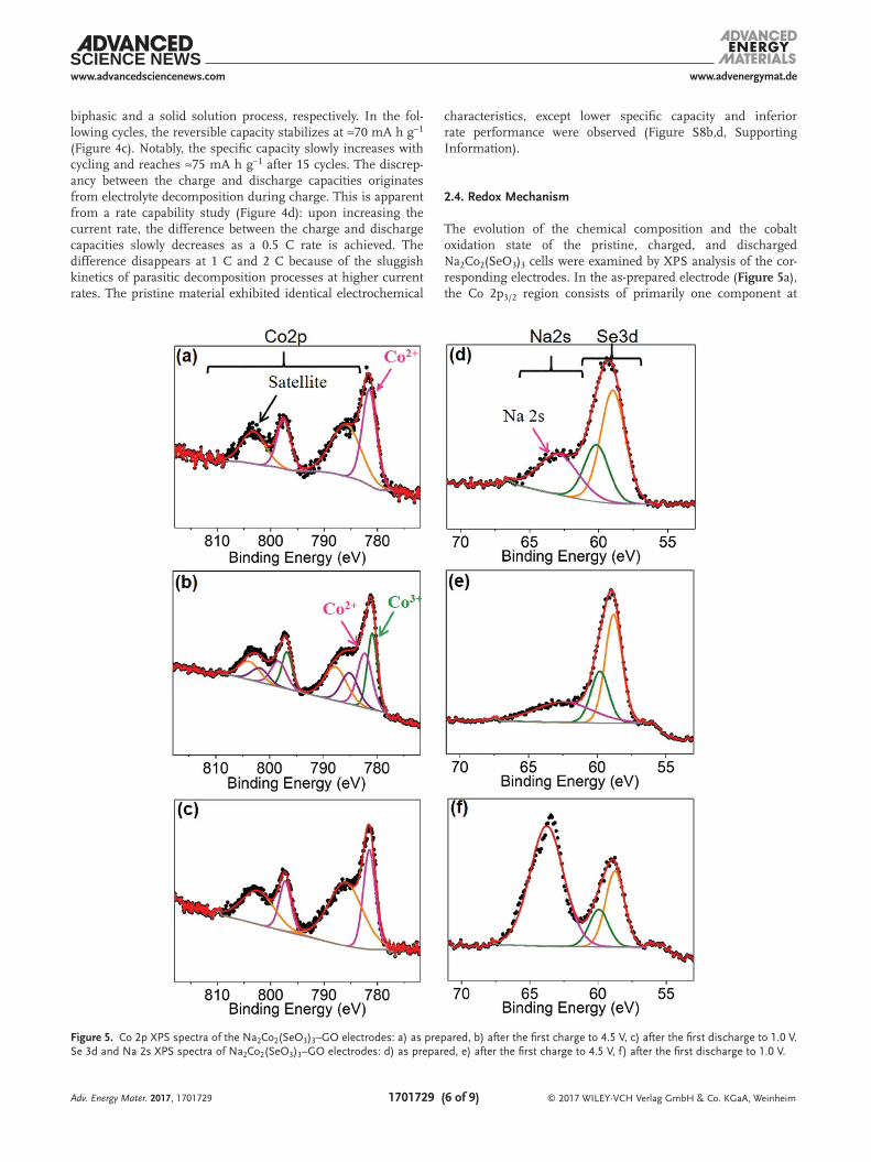
The evolution of the chemical composition and the cobalt oxidation state of the pristine, charged, and discharged Na2Co2(SeO3)3 cells were examined by XPS analysis of the cor-responding electrodes. In the as-prepared electrode (Figure 5a), the Co 2p3/2 region consists of primarily one component at
Adv. Energy Mater. 2017, 1701729
Figure 5. Co 2p XPS spectra of the Na2Co2(SeO3)3–GO electrodes: a) as prepared, b) after the first charge to 4.5 V, c) after the first discharge to 1.0 V. Se 3d and Na 2s XPS spectra of Na2Co2(SeO3)3–GO electrodes: d) as prepared, e) after the first charge to 4.5 V, f) after the first discharge to 1.0 V.

www.advenergymat.dewww.advancedsciencenews.com
© 2017 WILEY-VCH Verlag GmbH & Co. KGaA, Weinheim1701729 (7 of 9)
781.5 eV in accord with the Co2+ state of the pristine compound. The broad peak centered at ≈786 eV corresponds to the shake-up satellite, which is present for a paramagnetic metal state such as high spin (HS) Co2+. For the sample charged to 4.5 V (Figure 5b), the Co 2p3/2 region was deconvoluted into two con-tributions, with both being necessary to achieve a good fit. One peak is at slightly lower binding energy (780.6 eV) vis a vis Co2+, consistent with the partial conversion of Co2+ to Co3+.[38,39] The origin of the red shift is not well understood in the litera-ture. The other peak arises from residual Co2+, as the material does not fully oxidize on charge. The cobalt oxidation state is correlated to the amount of sodium that is deintercalated during charge (1.6 per formula unit as indicated by the electro-chemical studies, i.e., a little less than the theoretical 2e− redox per formula unit). While the Co2+ feature in the charged mate-rial represents a higher fraction than expected from the electro-chemistry, this is probably due to the fact that XPS probes the surface, not the bulk. Due to the subtlety (small shift of Co3+ w.r.t. Co2+) and complexities (shake-up final states) involved, the fit in Figure 5b is an exemplary fit, not quantitative. Two satellite features are also observed beside the primary Co 2p contributions, which indicates the paramagnetic nature of both Co2+ (HS) and Co3+ (intermediate spin (IS): t2g
5eg1) ions in the
charged compound.Upon subsequent discharge (Figure 5c), the Co 2p spectrum
returned to its initial state consisting of only the Co2+ com-ponent, implying a good reversibility of the cobalt redox pro-cess. Notably, no change in the selenium XPS component was observed for the charged/discharged materials (Figure 5d–f),
which confirms the lack of selenium redox activity. The inten-sity of the Na 2s peak, which appears to the right of the Se 3d XPS feature, is not in agreement with the true sodium content of the charged (see EDX data, above) and discharged mate-rials owing to residual surface Na+ contamination from the electrolyte.
The magnetic properties of the pristine and the charged/dis-charged materials were probed to further investigate the change in the oxidation state of the cobalt ion. All materials display Curie–Weiss paramagnetic behavior above 50 K as indicated by the linear fit of the reciprocal susceptibilities (Figure 6a–c) to the Curie–Weiss law
χθ
=−C
T (1)
where C is the molar curie constant, T is absolute tempera-ture, and θ is the Curie–Weiss temperature. The parameters obtained from the Curie–Weiss fitting are shown in Table S2 in the Supporting Information, where the effective magnetic moment (µeff) values were calculated from: µeff = 2.824 × C1/2. The magnetic moment obtained for pristine Na2Co2(SeO3)3 (4.23 µB mol−1 of Co) is consistent with typically observed values for Co2+ ions. These are higher than the spin-only value (3.87 µB) due to the spin-orbit contribution.[40] The charged material displays an effective moment (2.90 µB mol−1 of Co) that cannot be explained only by the magnetic moment of unoxidized Co2+ (high-spin (HS): t2g
5eg2; 0.4 of 2 Co). Thus,
we identify Co3+ as the source. Co3+ in both intermediate-spin
Adv. Energy Mater. 2017, 1701729
Figure 6. Variation of the inverse of the magnetic susceptibilities with temperature (black) and their fit to the Curie–Weiss (red) law above 50 K for the a) as prepared, b) charged, and the c) discharged Na2Co2(SeO3)3–GO electrodes. d) Variation of the magnetic susceptibilities with temperature for the as-prepared (black), charged (red), and the discharged (blue) Na2Co2(SeO3)3.

www.advenergymat.dewww.advancedsciencenews.com
© 2017 WILEY-VCH Verlag GmbH & Co. KGaA, Weinheim1701729 (8 of 9)Adv. Energy Mater. 2017, 1701729
(IS) (t2g5eg
1–spin-only µeff: 2.83 µB; 1.45 of 2 Co) and low spin (LS) (t2g
6 eg0—µeff: 0 µB; 0.15 of 2 Co) states are needed
to explain the observed moment. An IS-state of Co3+ is often observed in oxides, particularly when Jahn-Teller distortion is significant due to the local distortion of CoO6 octahedra.[41] In Na2Co2(SeO3)3, the CoO bond lengths are shorter out-of-plane than in-plane, thus favoring Jahn–Teller distortion on oxidation and hence the IS state. Therefore, we speculate that upon Na+ removal, HS Co2+ is initially oxidized to IS Co3+, with a small fraction of LS Co3+ forming only at the very end of charge leading to Na0.4Co0.4(HS)
2+Co1.45(IS)3+Co3+
0.15(LS)(SeO3)3. After dis-charge, the effective moment per cobalt ion closely resembles the pristine material, which confirms the reversibility of the cobalt redox upon electrochemical cycling. Furthermore, nearly superimposable magnetic susceptibility plots (Figure 6d) of the pristine and the discharged materials, where both display anti-ferromagnetic coupling below ≈14 K, provide substantial confir-mation for the electrochemical reversibility of the system.
3. Conclusions
In a search for novel polyanionic NIB cathode host materials in the transition metal selenite system, we developed a rapid and versatile microwave solvothermal synthesis route for nano-structured Na2Co2(SeO3)3 and its GO composite. In a NIB, the material delivers a reversible capacity of ≈75 mA h g−1 at a potential of ≈4 V. Among high voltage NIB cathodes, this is the second highest Co2+/3+ redox potential after Na4Co3(PO4)2P2O7 (≈90 mA g−1 and 4.5 V)[20] and is more compatible with organic electrolytes. Furthermore, Na2Co2(SeO3)3 is stable to air and moisture unlike higher voltage cathode materials. While oper-ando XRD investigation revealed a good structural reversibility during electrochemical cycling —with a predominantly solid solution mechanism and a relatively small volume change (4.7%) between the Na+ intercalated and deintercalated members—XPS and magnetic susceptibility studies provided evidence for good chemical reversibility. The electrochemical process is based on the Co2+/Co3+ redox couple, which is difficult to access in cobalt-based polyanionic compounds. This is the first example of a Na+ insertion compound based on a selenite polyanionic system. While our findings are not directed toward a commercially viable system, we hope that the fundamental understanding achieved in this work will pave the way for further discovery efforts to find new host materials for Na-ion battery applications.
4. Experimental Section
Synthesis: Nanostructured Na2Co2(SeO3)3 and the Na2Co2(SeO3)3–GO composites were prepared by employing a rapid and scalable microwave hydrothermal method. Water interacts strongly with microwave irradiation through a dipole-microwave interaction, which leads to local superheated regions in the reaction media. While typical hydrothermal methods involve slow heating via a convection mechanism, microwave irradiation of the entire reaction media triggers rapid nucleation leading to more homogeneous particles. For the synthesis of Na2Co2(SeO3)3, a stoichiometric mixture of Na2SeO3 (99.8%, Sigma Aldrich) and anhydrous CoCl2 (Purum p.a., ≥98.0% (KT), Sigma Aldrich) was dissolved in deionized (DI) water to give a total material concentration
of 1 m. An over-stoichiometric amount of Na2SeO3 was used to yield a pH of ≈10, and an equal volume of acetonitrile was added to this solution. The resultant mixture was placed in Teflon vessels, which were fitted to a rotor equipped with temperature and pressure sensors and placed in an Anton Parr microwave synthesis system (Synthos 3000). The system temperature was raised to 150 °C in 15 min and maintained for 30 min while the reaction mixture was magnetically stirred. The as-synthesized product was thoroughly washed with DI water, followed by a small volume of ethanol, and dried at 100 °C for 24 h. The same protocol was applied for the synthesis of the Na2Co2(SeO3)3–GO composite, where a 5 wt% GO suspension (prepared by the Hummers method) in water was used as the GO source.[42]
Powder X-Ray Diffraction(XRD): Powder XRD was performed on a Bruker D8-Advance powder diffractometer equipped with a Vantec-1 detector, using Cu Kα radiation (λ = 1.5405 Å) in the range from 10° to 80° (2θ) at a step size of 0.025° with Bragg–Brentano geometry. X-ray data refinement was carried out by a conventional Rietveld refinement method using the FullProf Suite program and the crystal structure was plotted using VESTA 3D visualization software.[43]
Operando X-Ray Diffraction(XRD): Operando XRD experiments were conducted using a homemade cell mounted on a PANalytical Empyrean diffractometer. The diffraction patterns were collected in Bragg–Brentano geometry using Cu-Kα radiation and a PIXcel detector with a Ni Kβ filter. The operando cell was cycled at a rate of C/20 with an XRD pattern collection time of ≈30 min. The evolution of lattice parameters during charge/discharge was determined by means of Le Bail fitting of the patterns.
Scanning Electron Microscopy (SEM): The morphologies of the materials were analyzed by a field emission scanning electron microscope (FE-SEM, LEO 1530) where the elemental mapping of Na, Co, Se, and O was carried out using the EDX imaging function.
Transmission Electron Microscopy(TEM): High Resolution TEM (HRTEM) samples were dispersed in isopropanol by ultrasonication and loaded on to a carbon-coated copper grid for imaging on JEOL 1200EX.
Electrochemical Impedance Spectroscopy (EIS) and Ionic Conductivity: The Na2Co2(SeO3)3 powder was pressed into a pellet of 0.92 mm in thickness and 11.27 mm in diameter using an uniaxial Carver press under a pressure of 6 ton cm−2. A silver conductive paste was applied to both sides of the pellet before mounting it in a symmetric Swagelok-type cell. The bulk resistance of the pellet was measured using two-probe ac impedance spectroscopy (VMP3, Bio-Logic) in a frequency range of 1 MHz to 10 mHz using a potentiostatic signal perturbation of 200 mV. Impedance spectroscopy data were recorded in a temperature range of 25 to 170 °C. Bulk ionic conductivities at different temperatures were obtained by fitting the Nyquist plot using EC-lab Z-fit analysis software. The Ea for Na-ion migration was obtained by linear fitting of the ionic conductivity values at different temperatures by applying the Arrhenius equation, modified to include a temperature dependent pre-exponential: σT = σ0 exp (−Ea/kbT), where σ is the temperature dependent ionic conductivity, σ0 is the ionic conductivity at absolute zero temperature, Ea is the activation energy of ion migration, and kb and T have their usual meanings.
Thermal Analysis: Thermogravimetric analysis and Differential Thermal Analysis (TG-DTA) was performed using a TG-DTA instrument SDT Q600 in air at a heating rate of 5 °C min−1.
X-ray Photoelectron Spectroscopy (XPS): XPS analysis was performed on a Thermo ESCALAB 250 instrument configured with monochromatic Al Kα radiation. The air-sensitive electrode samples were transported to the spectrometer in an Ar atmosphere and transferred into the chamber with less than 5 s exposure to air. All spectra were fitted with Gaussian–Lorentzian functions and a Shirley-type background using CasaXPS software. The binding energy values were calibrated using the C 1s peak at 284.8 eV. For the fitting of the 2p (Co) component pairs, a peak area ratio of 2:1 for 2p3/2: 2p1/2 was used with 2p1/2 having the higher value of full width at half maximum.
Magnetic Susceptibility Measurements: Magnetic susceptibility measurements on the pristine and charged/discharged samples were performed as a function of temperature using a MPMS SQUID VSM magnetometer (Quantum Design Inc.) in a magnetic field of 1000 Oe upon cooling the samples from 350 to 2 K.

www.advenergymat.dewww.advancedsciencenews.com
© 2017 WILEY-VCH Verlag GmbH & Co. KGaA, Weinheim1701729 (9 of 9)Adv. Energy Mater. 2017, 1701729
Electrochemistry: Electrochemical properties of the materials were evaluated in 2325 coin cells using Na metal as the counter electrode. Coin cell assembly was performed inside a glove box under argon (O2 and H2O < 0.1 ppm). For electrode fabrication, the Na2Co2(SeO3)3–GO composite was mixed with carbon black and polyvinylidene fluoride (average Mw ≈ 534 000, Sigma Aldrich) to achieve a final weight ratio of active material: carbon: binder in the cathode of 70:25:5. The weight of GO in the composite was taken into account for this formulation. The mixture was suspended in N-methyl-2-pyrrolidinone (99.5%, Sigma Aldrich) to obtain a viscous slurry, which was cast on aluminum foil with a typical loading of 4–5 mg cm−2. Electrodes of 1 cm2 geometric area were punched and dried at 120 °C in a vacuum oven. A mixture of 1 m sodium hexafluorophosphate (≥98%, Alfa Aesar; dried for 24 h at 120 °C in a glass oven under dynamic vacuum) in propylene carbonate (BASF, 99.98%), and ethylene carbonate (BASF, 99.98%) in a ratio of 1:1 (by volume) was used as the electrolyte. The electrodes were separated by glass fiber separators (Merck Millipore), which were dried at 300 °C for 24 h under dynamic vacuum prior to use. Galvanostatic cycling and cyclovoltammetry tests were conducted at 23 °C within a potential window of 1.0–4.5 V (vs Na/Na+) using an MPG-2 (Bio-Logic) battery tester.
Supporting InformationSupporting Information is available from the Wiley Online Library or from the author.
AcknowledgementsS.Y.K. and D.K. contributed equally to this work. The authors thank the Natural Sciences and Engineering Council of Canada for generous financial support of this work through their Discovery and Canada Research Chair programs, and BASF SE for ongoing support through the research network in Electrochemistry and Batteries.
Conflict of InterestThe authors declare no conflict of interest.
Keywordsmicrowave hydrothermal synthesis, polyanionic cathode materials, sodium-ion batteries, transition metal selenites
Received: June 25, 2017Revised: July 23, 2017
Published online:
[1] N. Yabuuchi, K. Kubota, M. Dahbi, S. Komaba, Chem. Soc. Rev. 2014, 114, 11636.
[2] D. Kundu, E. Talaie, V. Duffort, L. F. Nazar, Angew. Chem. 2015, 127, 3495; Angew. Chem., Int. Ed. Engl. 2015, 54, 3431.
[3] B. L. Ellis, L. F. Nazar, Curr. Opin. Solid State Mater. Sci. 2012, 16, 168.[4] M. Armand, J. M. Tarascon, Nature 2008, 451, 652.[5] B. Scrosati, J. Hassoun, Y. K. Sun, Energy Environ. Sci. 2011, 4, 3287.[6] B. Scrosati, J. Garche, J. Power Sources 2010, 195, 2419.[7] T. Kodama, H. Sakaebe, J. Power Sources 1999, 81, 144.[8] V. Palomares, P. Serras, I. Villaluenga, K. B. Hueso,
J. Carretero-Gonzalez, T. Rojo, Energy Environ. Sci. 2012, 5, 5884.[9] M. D. Slater, D. Kim, E. Lee, C. S. Johnson, Adv. Funct. Mater. 2013,
23, 947.
[10] V. Etacheri, R. Marom, R. Elazari, G. Salitra, D. Aurbach, Energy Environ. Sci. 2011, 4, 3243.
[11] S. W. Kim, D. H. Seo, X. H. Ma, G. Ceder, K. Kang, Adv. Energy Mater. 2012, 2, 710.
[12] N. Yabuuchi, M. Kajiyama, J. Iwatate, H. Nishikawa, S. Hitomi, R. Okuyama, R. Usui, Y. Yamada, S. Komaba, Nat. Mater. 2012, 11, 512.
[13] S. Komaba, C. Takei, T. Nakayama, A. Ogata, N. Yabuuchi, Electrochem. Commun. 2010, 12, 355.
[14] S. P. Ong, V. L. Chevrier, G. Hautier, A. Jain, C. Moore, S. Kim, X. H. Ma, G. Ceder, Energy Environ. Sci. 2011, 4, 3680.
[15] M. Sathiya, K. Hemalatha, K. Ramesha, J. M. Tarascon, A. S. Prakash, Chem. Mater. 2012, 24, 1846.
[16] J. Billaud, R. J. Clement, A. R. Armstrong, J. Canales-Vazquez, P. Rozier, C. P. Grey, P. G. Bruce, J. Am. Chem. Soc. 2014, 136, 17243.
[17] Y. U. Park, D. H. Seo, H. S. Kwon, B. Kim, J. Kim, H. Kim, I. Kim, H. I. Yoo, K. Kang, J. Am. Chem. Soc. 2013, 135, 13870.
[18] P. Barpanda, G. Oyama, S. Nishimura, S. C. Chung, A. Yamada, Nat. Commun. 2014, 5, 4358.
[19] C. Masquelier, L. Croguennec, Chem. Rev. 2013, 113, 6552.[20] M. Nose, H. Nakayama, K. Nobuhara, H. Yamaguchi, S. Nakanishi,
H. Iba, J. Power Sources 2013, 234, 175.[21] P. Barpanda, J. C. Lu, T. Ye, M. Kajiyama, S. C. Chung, N. Yabuuchi,
S. Komaba, A. Yamada, RSC Adv. 2013, 3, 3857.[22] P. Barpanda, G. D. Liu, C. D. Ling, M. Tamaru, M. Avdeev,
S. C. Chung, Y. Yamada, A. Yamada, Chem. Mater. 2013, 25, 3480.
[23] J. C. Treacher, S. M. Wood, M. S. Islam, E. Kendrick, Phys. Chem. Chem. Phys. 2016, 18, 32744.
[24] X. H. Lin, Y. Z. Dong, Q. Kuang, D. L. Yan, X. D. Liu, W. Han, Y. M. Zhao, J. Solid State Electrochem. 2016, 20, 1241.
[25] A. Gutierrez, S. Kim, T. T. Fister, C. S. Johnson, ACS Appl. Mater. Interfaces 2017, 9, 4391.
[26] H. L. Pan, Y. S. Hu, L. Q. Chen, Energy Environ. Sci. 2013, 6, 2338.[27] Z. L. Gong, Y. Yang, Energy Environ. Sci. 2011, 4, 3223.[28] M. Wildner, J. Solid State Chem. 1993, 103, 341.[29] R. E. Morris, A. K. Cheetham, Chem. Mater. 1994, 6, 67.[30] M. Wildner, J. Alloys Compd. 1995, 217, 209.[31] M. Wildner, Acta Crystallogr., Sect. C: Struct. Chem. 1994, 50, 336.[32] X. Q. Yuan, M. L. Feng, J. R. Li, X. Y. Huang, J. Solid State Chem.
2010, 183, 1955.[33] W. X. Song, X. B. Ji, C. C. Pan, Y. R. Zhu, Q. Y. Chen, C. E. Banks,
Phys. Chem. Chem. Phys. 2013, 15, 14357.[34] J. Liu, D. H. Chang, P. Whitfield, Y. Janssen, X. Q. Yu, Y. N. Zhou,
J. M. Bai, J. Ko, K. W. Nam, L. J. Wu, Y. M. Zhu, M. Feygenson, G. Amatucci, A. Van der Ven, X. Q. Yang, P. Khalifah, Chem. Mater. 2014, 26, 3295.
[35] M. A. Evstigneeva, V. B. Nalbandyan, A. A. Petrenko, B. S. Medvedev, A. A. Kataev, Chem. Mater. 2011, 23, 1174.
[36] Y. J. Zhu, Y. H. Xu, Y. H. Liu, C. Luo, C. S. Wang, Nanoscale 2013, 5, 780.
[37] Y. Yamashita, P. Barpanda, Y. Yamada, A. Yamada, ECS Electrochem. Lett. 2013, 2, A75.
[38] L. Daheron, R. Dedryvere, H. Martinez, M. Menetrier, C. Denage, C. Delmas, D. Gonbeau, Chem. Mater. 2008, 20, 583.
[39] D. H. Ge, J. J. Wu, G. L. Qu, Y. Y. Deng, H. B. Geng, J. W. Zheng, Y. Pan, H. W. Gu, Dalton Trans. 2016, 45, 13509.
[40] L. Tao, J. R. Neilson, B. C. Melot, T. M. McQueen, C. Masquelier, G. Rousse, Inorg. Chem. 2013, 52, 11966.
[41] C. Zobel, M. Kriener, D. Bruns, J. Baier, M. Gruninger, T. Lorenz, P. Reutler, A. Revcolevschi, Phys. Rev. B: Condens. Matter Mater. Phys. 2002, 66, 020402(R).
[42] W. S. Hummers, R. E. Offeman, J. Am. Chem. Soc. 1958, 80, 1339.[43] K. Momma, F. Izumi, J. Appl. Crystallogr. 2011, 44, 1272.