Embed Size (px)
Citation preview

SEABROOK STATION RELIEF VALVE PROGRAM
Roger Samson Bob Thomas
Plant Engineering Maintenance
PRDUG MEETING, ORLANDO, FLA.
JANUARY 24-26, 2001

Seabrook Relief Valve Team 2
SEABROOK STATION RELIEF VALVE PROGRAM
• Testing Video R. Samson / R. Thomas
• Program overview R. Samson
• ORO-7 Code Revision R. Samson
• Determination of testing parameters R. Samson
• Test Equipment / Facility development R. Thomas
• Data Package Revision For Hot TestingR. Thomas
• ORO-7 testing results R. Thomas / R. Samson
• EPRI Test Model R. Samson / R. Thomas
• Questions and Answers R. Samson / R. Thomas

Seabrook Relief Valve Team 3
Program Overview
• Last plant using ASME XI, 1983 Edition, Summer Addenda
No thermal relief valves
TWO PARAGRAPHS - PTC 25.3
Bench test at ambient temperature
• First plant using ASME O&M Code 1995 Edition, 1996 Addenda in its entirety
Thermal relief valves now included
Significant changes - prescriptive test requirements
(Test media and ambient air temp requirements)

Seabrook Relief Valve Team 4
SEABROOK STATION RELIEF VALVE PROGRAM
• Program overview R. Samson
• ORO-7 Code Revision R. Samson
• Determination of testing parameters R. Samson
• Test Equipment / Facility development R. Thomas
• Data Package Revision For Hot TestingR. Thomas
• ORO-7 testing results R. Thomas / R. Samson
• EPRI Test Model R. Samson / R. Thomas
• Questions and Answers R. Samson / R. Thomas

Seabrook Relief Valve Team 5
OR07 Code Revision
New prescriptive test requirements:
• Class 1 RV’s and MSSV’s – 5 years, 20% min. in 2 yrs.
• Class 2&3 RV’s – 10 years, 20% min. in 4 yrs.
• .Additional scope if failure occur
• .Replacement Valves – special testing requirements.
• .Rupture Disks – replace every 5 years.
• Instrumentation ‑ 1% of setpoint.

Seabrook Relief Valve Team 6
OR07 Code Revision
New prescriptive test requirements (con’t)
• Testing Sequence:Visual, Leak, Setpoint, Leak, Bellows
• Test Media same as operating, (e.g., steam, air, N2, water, oil, etc.).
• Test Media Temperature & Ambient Temperature
Operating vs. conditions when valve is expected to actuate
• Thermal Equilibrium Criteria, (10F change in 30 minutes)
• 10 Minutes between Lift Tests
• 2 Consecutive Lifts, (without adjustment)
• Alternate Test Media Correlation.

Seabrook Relief Valve Team 7
Significant Changes
Test Media Temperature & Ambient Temperature -
• Expected to perform its intended function
• These conditions also apply to Seat Tightness.
• Requires test equipment with “Hot” testing capabilities.

Seabrook Relief Valve Team 8
Significant Changes (con’t)
Alternate Test Media Correlation
• Permits testing using both cold ambient and media conditions provided that correlation test data exists to support cold testing.
• Some vendors had media correlation
• No vendors combined media and ambient temperature
• No vendors had ambient temperature correlation
• Some vendors refused to do alternate media testing

Seabrook Relief Valve Team 9
SEABROOK STATION RELIEF VALVE PROGRAM
• Program overview R. Samson
• ORO-7 Code Revision R. Samson
• Determination of testing parameters R. Samson
• Test Equipment / Facility development R. Thomas
• Data Package Revision For Hot TestingR. Thomas
• ORO-7 testing results R. Thomas / R. Samson
• EPRI Test Model R. Samson / R. Thomas
• Questions and Answers R. Samson / R. Thomas

Seabrook Relief Valve Team 10
Determination of testing parameters
Temperature Requirements - two methods:
• Normal system operating
Versus
• Conditions when valve is expected to perform its function
upset system or emergency accident condition
what function each valve was performing
what conditions were associated with its function
Document search included Technical Specifications, UFSAR, System Calculations and technical (T/P) sheets
Seabrook Relief Valve Team 11
Test valve
TEST GROUP NO. 4
Valve No. P&ID No. Train Class FP Manual Size TypeTest
Medium Setpoint
AcceptanceCriteria
(+0, - 3%)Leak Test Pressure
AcceptanceCriteria
RC-V24 1-RC-D20841 A 2 50457 C710-1 3" JB-35-TD-WR Water 450 psig 436.5 to 450 psig 405 to 410 psig 30 cc/hr
RC-V89 1-RC-D20844 B
SPEC 248-43 MEDIA
TEMPERATURE
(+/-10F)
SERVICE
ENVIRONMENT
AMBIENT
TEMPERATURE
(+/-10F)
TESTPROCEDURE
REPAIRPROCEDURE
REMARKS
R-32 350F Containment -Heatup and
Cooldown
120F EX1804.044 MS0519.13 RHR Suction Relief Valves-Heatup
and Cooldown.

Seabrook Relief Valve Team 12
SEABROOK STATION RELIEF VALVE PROGRAM
• Program overview R. Samson
• ORO-7 Code Revision R. Samson
• Determination of testing parameters R. Samson
• Test Equipment / Facility development R. Thomas
• Data Package Revision For Hot TestingR. Thomas
• ORO-7 testing results R. Thomas / R. Samson
• EPRI Test Model R. Samson / R. Thomas
• Questions and Answers R. Samson / R. Thomas

Seabrook Relief Valve Team 13
Test Equipment / Facility Development

Seabrook Relief Valve Team 14
Test Equipment / Facility developmentDesign Considerations
•SAFETY
•VOLUME CONTROL
•TEMPERATURE CONTROL
•ERGONOMIC OPERATOR CONTROLS

Seabrook Relief Valve Team 15
SAFETY
Due to the increased energy potential created by flashing fluids, special safety features were included in the equipment and facilities design.

Seabrook Relief Valve Team 16
SAFETY
RCA TEST STAND
Due to radiological release concerns, the RCA test stand discharge system includes an adjustable, sealed discharge pipe for each table and a vented discharge tank. The tank is equipped with a sparging system and has provisions for connection of a HEPA filter, if required.
COLD SIDE TEST STAND
The cold side test stand discharge system includes an adjustable, sealed discharge pipe and an exhaust pipe vented to atmosphere through the side of the building.

Seabrook Relief Valve Team 17
SAFETY
Quick Acting Valves
Quick acting air operated valves were added on the accumulator and table vent lines This allows for rapid venting if the pressure increases in the test stand due to internal flashing. Quick acting air operated valves were also added on the accumulator / table isolation valves in case of a stuck open valve.

Seabrook Relief Valve Team 18
Test Equipment / Facility developmentDesign Considerations
•SAFETY
•VOLUME CONTROL
•TEMPERATURE CONTROL
•ERGONOMIC OPERATOR CONTROLS

Seabrook Relief Valve Team 19
VOLUME CONTROL
Manual bypass valve on water side
Three rates of air feeds to the accumulator
Bypass line on the water circuit allows for low volume set pressure testing on smaller valves or when lifting larger valves is undesirable.
Three rates of air feed to accumulator lets the operator vary the fill rate and air volume from air storage to accumulator.

Seabrook Relief Valve Team 20
VOLUME CONTROL
Restricting Devices
Valves are often partially gagged to restrict lift and conserve heated water.

Seabrook Relief Valve Team 21
Test Equipment / Facility developmentDesign Considerations
•SAFETY
•VOLUME CONTROL
•TEMPERATURE CONTROL
•ERGONOMIC OPERATOR CONTROLS
Seabrook Relief Valve Team 22
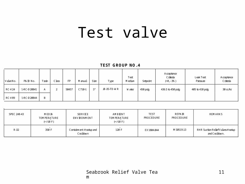
TEMPERATURE CONTROL
Local Controllers
Each heat zone has a local controller to program final temperature settings, and ramp rates
Separate Heat Zones
Vessel, piping, and environmental chambers are divided into seperate heating zones for variable heat control.

Seabrook Relief Valve Team 23
Test Equipment / Facility developmentDesign Considerations
•SAFETY
•VOLUME CONTROL
•TEMPERATURE CONTROL
•ERGONOMIC OPERATOR CONTROLS

Seabrook Relief Valve Team 24
ERGONOMIC OPERATOR CONTROLS
Seabrook Relief Valve Team 25
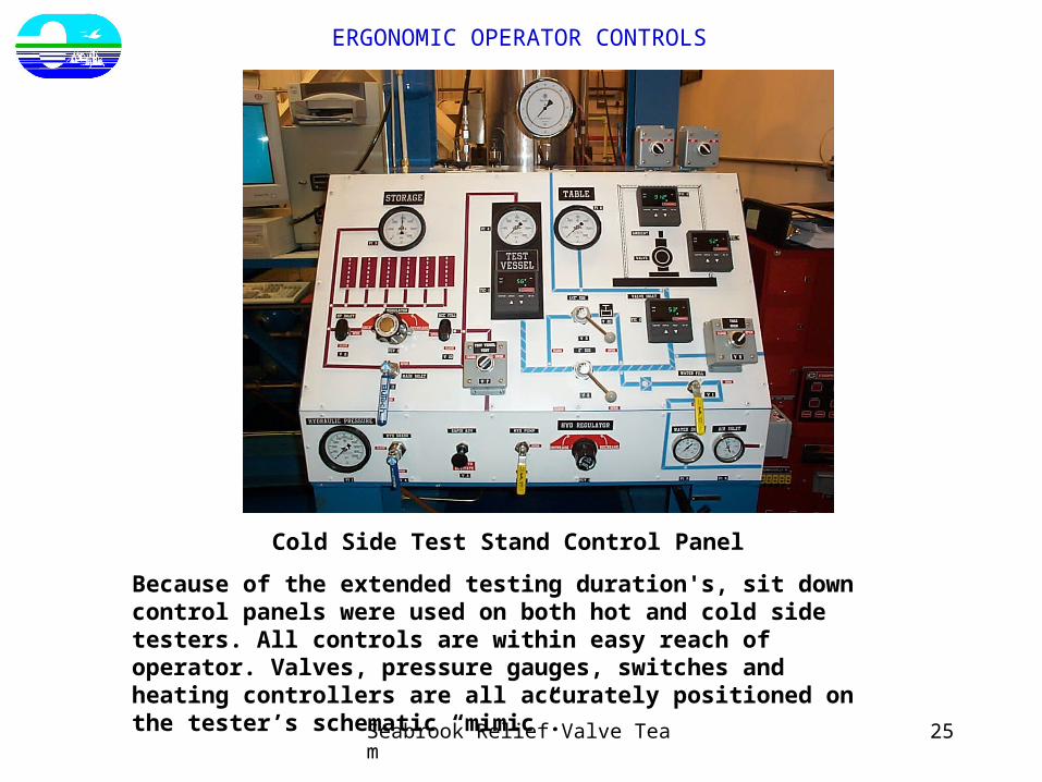
Cold Side Test Stand Control Panel
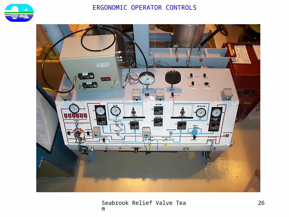
Because of the extended testing duration's, sit down control panels were used on both hot and cold side testers. All controls are within easy reach of operator. Valves, pressure gauges, switches and heating controllers are all accurately positioned on the tester’s schematic “mimic”.
ERGONOMIC OPERATOR CONTROLS
Seabrook Relief Valve Team 26
ERGONOMIC OPERATOR CONTROLS

Seabrook Relief Valve Team 27
ERGONOMIC OPERATOR CONTROLS

Seabrook Relief Valve Team 28
ERGONOMIC OPERATOR CONTROLS

Seabrook Relief Valve Team 29
SEABROOK STATION RELIEF VALVE PROGRAM
• Program overview R. Samson
• ORO-7 Code Revision R. Samson
• Determination of testing parameters R. Samson
• Test Equipment / Facility development R. Thomas
• Data Package Revision For Hot TestingR. Thomas
• ORO-7 testing results R. Thomas / R. Samson
• EPRI Test Model R. Samson / R. Thomas
• Questions and Answers R. Samson / R. Thomas

Seabrook Relief Valve Team 30
Data Package Revision For Hot Testing

Seabrook Relief Valve Team 31
SETPOINT VERIFICATION / DATA ACQUISITION
SETPOINT VERIFICATION

Seabrook Relief Valve Team 32
SETPOINT VERIFICATION / DATA ACQUISITION
SETPOINT VERIFICATION
Seabrook Relief Valve Team 33
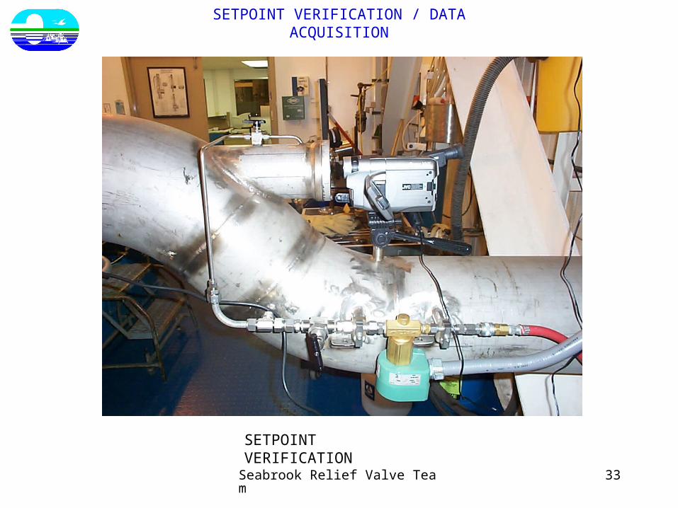
SETPOINT VERIFICATION / DATA ACQUISITION
SETPOINT VERIFICATION

Seabrook Relief Valve Team 34
SETPOINT VERIFICATION / DATA ACQUISITION
Cold SideTester Piping Hot Side Tester Piping

Seabrook Relief Valve Team 35
SETPOINT VERIFICATION / DATA ACQUISITION
Seabrook Relief Valve Team 36
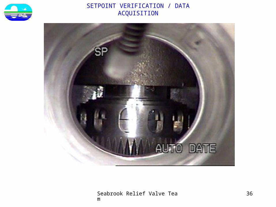
SETPOINT VERIFICATION / DATA ACQUISITION

Seabrook Relief Valve Team 37
SETPOINT VERIFICATION / DATA ACQUISITION

Seabrook Relief Valve Team 38
SETPOINT VERIFICATION / DATA ACQUISITION

Seabrook Relief Valve Team 39
SETPOINT VERIFICATION / DATA ACQUISITION

Seabrook Relief Valve Team 40
SEABROOK STATION RELIEF VALVE PROGRAM
• Program overview R. Samson
• ORO-7 Code Revision R. Samson
• Determination of testing parameters R. Samson
• Test Equipment / Facility development R. Thomas
• Data Package Revision For Hot TestingR. Thomas
• ORO-7 testing results R. Thomas / R. Samson
• EPRI Test Model R. Samson / R. Thomas
• Questions and Answers R. Samson / R. Thomas

Seabrook Relief Valve Team 41
OR07 Test Results
• New Scope thermal relief valves - near 100%
• One LER - RH Suction Relief Valve lifted low
• Expanded scope for several groups
Containment
Component Cooling system
• 2 Rupture Disc replaced
• Oil tests - DG System

Seabrook Relief Valve Team 42
OR07 Test ResultsGroup Valve ID Set As Found Delta Ambient Media Size Manufacture Status
Pressure Pressure Pressure Temp Temppsig psig psig (F) (F)
01 1-cc-v-474 150 149 1 273 97 1.5x2 Lonergan
04 1-rc-v-24 450 415 35 120 350 3x4 Crosby Outside Tolerance
04 1-rc-v-89 450 452 2 120 350 3x4 Crosby EXPANSION
05 1-cbs-v-96 350 359 9 104 104 3/4x1 Lonergan
05 1-cbs-v-94 350 345 5 0 0 3/4x1 Lonergan
06 1-cbs-v-149 325 300 25 104 350 3/4x1 Crosby Outside Tolerance
06 1-cbs-v-150 325 340 -15 104 350 3/4x1 Crosby Outside Tolerance-EXPANSION
06 1-cbs-v-151 325 325 0 104 350 3/4x1 Crosby EXPANSION
06 1-cbs-v-152 325 320 5 104 350 3/4x1 Crosby EXPANSION
07 1-cs-v-227 220 198 22 220 180 .75 x 1 Crosby Outside Tolerance
07 1-cbs-v-62 220 204 16 180 189 3/4x1 Crosby Outside Tolerance-EXPANSION
08 1-wld-v-213 150 150 0 273 120 1.5 Lonergan
09 1-sf-v-183 150 148 2 104 75 .75 x 1 Lonergan
09 1-sf-v-45 150 148 2 104 75 .75 x 1 Lonergan
09 1-sf-v-74 150 160 10 104 75 .75 x 1 Lonergan Outside Tolerance
10 1-cs-v-250 150 147 3 198 130 2.0 Crosby
11 1-rc-v-337 2485 2412 73 273 120 .75 x 1 Lonergan
12 1-rc-v-312 2485 2165 320 273 120 .75 Lonergan Outside Tolerance
12 1-rc-v-314 2485 2290 195 273 120 .75 x 1 Lonergan Outside Tolerance-EXPANSION
12 1-si-v-247 2485 2483 2 273 120 .75 x 1 Lonergan EXPANSION

Seabrook Relief Valve Team 43
OR07 Test ResultsGroup Valve ID Set As Found Delta Ambient Media Size Manufacture Status
Pressure Pressure Pressure Temp Temppsig psig psig (F) (F)
13 1-si-v-101 1750 1724 26 104 120 .75 x 1 Crosby
14 1-si-v-60 700 712 12 120 120 1.0 x 2 Crosby
15 1-rh-v-57 600 615 15 104 120 .75 x 1 Crosby
17 1-cc-v-407 150 148 2 104 260 1.5 Lonergan
17 1-cc-v-409 150 154 4 104 278 1.5 Lonergan
18 1-cc-v-343 150 152 2 104 350 2.0 x 3 Lonergan
20 1-cc-v-26 150 135 15 104 260 .75 Lonergan Outside Tolerance
20 1-cc-v-141 150 144 6 104 350 .75 Lonergan Outside Tolerance
20 1-cc-v-1277 150 154 -4 130 130 3/4 X 1 Lonergan EXPANSION
20 1-cc-v-1278 150 156 6 130 130 3/4 x 1 Lonergan Outside Tolerance-EXPANSION
20 1-cc-v-1279 150 161 11 158 150 .75 Lonergan Outside Tolerance-EXPANSION
20 1-cc-v-262 150 162 12 104 260 .75 Lonergan Outside Tolerance-EXPANSION
20 1-cc-v-269 150 148 2 104 350 .75 Lonergan EXPANSION
20 1-cc-v-30 150 147 7 104 350 .75 Lonergan Outside Tolerance-EXPANSION
20 1-cc-v-320 150 156 6 104 350 .75 Lonergan Outside Tolerance-EXPANSION
20 1-cc-v-321 150 159 9 104 350 .75 Lonergan Outside Tolerance-EXPANSION
20 1-cc-v-322 150 150 0 104 260 .75 Lonergan EXPANSION
20 1-cc-v-342 150 147 3 104 151 .75 Lonergan EXPANSION
21 1-dg-v-118 55 55 0 114 120 1.5 x 2 Lonergan
21 1-dg-v-124 55 54 1 114 120 1.5 x 2 Lonergan
22 1-dg-v-211a 70 68 2 113 135 .75 x 1 Circle Seal

Seabrook Relief Valve Team 44
OR07 Test ResultsGroup Valve ID Set As Found Delta Ambient Media Size Manufacture Status
Pressure Pressure Pressure Temp Temppsig psig psig (F) (F)
22 1-dg-v-211b 70 74 4 113 135 .75 x 1 Circle Seal Outside Tolerance
23 1-sw-v-514a 145 171 26 113 135 .75 x 1 Circle Seal Outside Tolerance
23 1-sw-v-514b 145 170 25 113 135 .75 Circle Seal Outside Tolerance
24 1-cc-v-1105 150 146 4 273 175 .75 Lonergan
26 1-sw-v-32 150 152 2 104 175 2.0 x 3 Crosby
26 1-sw-v-73 150 205 55 104 175 2.0 Lonergan Outside Tolerance
27 1-cs-v-48 600 594 6 273 290 2 x 3 Lonergan
41 1-cs-v-834 300 330 30 104 104 .75 x 1 CON. 1975 Outside Tolerance
47 1-hd-v-232 170 176 6 80 350 .75 x 1 consolidated Outside Tolerance
53 1-co-v-430 150 151 1 80 100 .75 x 1 CON. 1975c
Seabrook Relief Valve Team 45
SEABROOK STATION RELIEF VALVE PROGRAM
• Program overview R. Samson
• ORO-7 Code Revision R. Samson
• Determination of testing parameters R. Samson
• Test Equipment / Facility development R. Thomas
• Data Package Revision For Hot TestingR. Thomas
• ORO-7 testing results R. Thomas / R. Samson
• EPRI Test Model R. Samson / R. Thomas
• Questions and Answers R. Samson / R. Thomas

Seabrook Relief Valve Team 46
EPRI Test Model
The plan involved 60 lifts, 10 at each set of ambient and fluid temperatures. The first three tests will evaluate fluid temperature effects alone. The next two (when combined with the first) will evaluate the effects of ambient temperature alone. The final test when compared to the first will evaluate the combined effects of fluid and ambient temperature increases. By conducting 10 lifts at each test condition we will obtain excellent statistical confidence in the observed mean values from each data set.
EPRI will begin the development of the thermal model with the intention of predicting the set point changes resulting from the testing described above. Based on the results of this effort, EPRI will be able to develop a cost effective research plan for validating the model for the full range of class 2 and 3 relief valve designs in use in the industry. In addition, the data obtained will provide very significant insights into the effects of fluid and ambient temperatures on relief valve set points.
Fluid Temperature (F) Ambient Temperature (F) Number of lifts80 80 10
150 80 10350 80 1080 150 1080 350 10
350 350 10
Shortly after our facility was declared operational EPRI was invited for a facility tour and demonstration. After the visit EPRI requested that Seabrook run a series of tests at various combinations of fluid and ambient temperatures. Seabrook agreed to perform the testing which was completed in late November.


![Servo Actuators FLA - Harmonic Drive SE · FLA Actuators without hollow shaft Table 14.1 Technical data Table 14.2 Symbol [Unit] FLA-11A-xxFB FLA-14A-xxFB FLA-17A-xxFB FLA-20A-xxFB](https://img.pdfslide.net/doc/110x75/5fd5fffdc37b2c5c172eeba3/servo-actuators-fla-harmonic-drive-se-fla-actuators-without-hollow-shaft-table.jpg)