Embed Size (px)
Citation preview

Seagate Technology
STT8000 ATAPI Minicartridge Drive
Product Description Manual
July 1997
Part Number 10002475-003Stocking Number 601-087


FCC Notice
This equipment generates and uses radio frequency energy and if not installedand used properly—that is, in strict accordance with the manufacturer'sinstructions—may cause interference to radio and television reception. It hasbeen type tested and found to comply with the limits for a Class B computingdevice in accordance with the specifications in Part 15 of FCC Rules, which aredesigned to provide reasonable protection against such interference in aresidential installation. However, there is no guarantee that interference willnot occur in a particular installation. If this equipment does cause interferenceto radio or television reception, which can be determined by turning theequipment on and off, you are encouraged to try to correct the interference byone or more of the following measures:
z Reorient the receiving antenna.
z Relocate the computer with respect to the receiver.
z Move the computer into a different outlet so that the computer and receiverare on different branch circuits.
If necessary, you should consult the dealer or an experienced radio/televisiontechnician for additional suggestions. You may find the following bookletprepared by the Federal Communications Commission helpful:
How to Identify and Resolve Radio-TV Interference Problems
This booklet (Stock No. 004-000-00345-4) is available from the U.S. GovernmentPrinting Office, Washington, DC 20402.
Warning: Changes or modifications made to this equipment which have notbeen expressly approved by Seagate Technology may cause radio and televisioninterference problems that could void the user's authority to operate theequipment.
Further, this equipment complies with the limits for a Class B digital apparatusin accordance with Canadian Radio Interference Regulations.
Cet appareil numérique de la classe B est conforme au Règlement sur brouillageradioélectrique, C. R. C., ch. 1374.
Seagate and the Seagate logo are registered trademarks of Seagate Technology.All other trademarks mentioned in this manual are the property of theirrespective owners.
Copyright 1996, Seagate TechnologyAll rights reserved.
Document No. 10002475-003Stocking No. 601-087

Important Information About This Manual
All information contained in or disclosed by this document is consideredproprietary by Seagate Technology. By accepting this material, the recipientagrees that this material and the information contained therein are held inconfidence and in trust and will not be used, reproduced in whole or in part, norits contents revealed to others, except to meet the purpose for which it wasdelivered. It is understood that no right is conveyed to reproduce or translateany item herein disclosed without express written permission from SeagateTechnology.
Seagate Technology provides this manual "as is," without warranty of any kind,either expressed or implied, including, but not limited to, the impliedwarranties of merchantability and fitness for a particular purpose. SeagateTechnology reserves the right to change, without notification, the specificationscontained in this manual.
Seagate Technology assumes no responsibility for the accuracy, completeness,sufficiency, or usefulness of this manual, nor for any problem that might arisefrom the use of the information in this manual.

Product Description Manual Page v
Table of Contents
1 Introduction 1
Overview 1Features 3Typical System Configurations 4Minicartridge Technology Overview 4Flash EEPROM 5Software 5References 6About This Manual 6
2 Specifications 7
Overview 7Physical Specifications 7Power Specifications 9Drive Performance Specifications 10Environmental Requirements 11Recommended Tapes 11Tape Capacities and Formats 12Regulatory Compliance 12
3 Installation 13
Introduction 13Before You Begin 13
Check the Package Contents 13Guidelines 14
Installation Summary (Default) 14Installing the Seagate IDE Adapter Card 15Installing the Drive Unit 17Custom Installation with the Seagate IDE Adapter Card 23Configuring the Seagate IDE Adapter Card 24
4 Drive Operations 27
Introduction 27Front Panel LED Operation 27Using Cartridges 28
Loading and Unloading Tape Cartridges 28Setting the Write-Protect Switch 29
Loading Revised Firmware via Seagate FirmwareCartridge 30
Table of Contents
Page vi STT8000 ATAPI Minicartridge Drive
5 ATAPI Interface 33
Introduction 33ATA-2 Interface 33
ATA-2 Signals 33ATA Registers 34Supported ATA Commands 36
ATAPI Interface 39
6 Tape Format 55
Introduction 55Tape Partitioning 55Track Positions 55Track Numbering 56Track Format 56
Frames 56Blocks 58
Tape Reference Servo Pattern 58Write Equalization 59Randomization 59
7 Theory of Operations 61
Overview 61Block Diagrams 61Understanding the Drive 61Mechanics 63
Cartridge Load Mechanism 63Capstan Drive Motor Assembly 63Chassis 63
Control Circuits 63Head Design 64Flash EEPROM 64Sensors and Switches 64Media—Minicartridges 65
8 Maintenance, Troubleshooting, andReliability 67
Maintenance 67Caring for Tape Cartridges 67Cleaning the Drive Read/Write Head 67
Troubleshooting 68Reliability 70
Mean-Time-Between Failures 70Mean-Time-To-Repair 70

Table of Contents
Product Description Manual Page vii
A Glossary 71
B Acronyms and Measurements 75
Acronyms and Abbreviations 75Measurements 76

Table of Contents
Page viii STT8000 ATAPI Minicartridge Drive
NOTES

Product Description Manual Page 1
Introduction
Overview
The Seagate STT8000 ATAPI minicartridge drive extends the Seagate family ofone-inch high, DC2000 drives that feature high performance, high reliability,and quiet operation. The drive transfers data at up to 36 megabytes per minute(MB/min) without compression. With optimal system resources andcompressible data structures, nominal transfer rates of 60 MB/min can beobserved using software data compression (assumes 2:1 compression ratio).
The system optimizations include but are not limited to
z Allocating the maximum amount of the base 640 KB memory available
z Using a memory manager program
Note: During backup tasks, screen savers can have a negative affect ontransfer rates.
Data compression is available within the Seagate Backup software package forDOS and Windows and typically provides for a 2:1 compression ratio. Thecompression ratio is dependent on the specific system and the nature of the filesbeing compressed.
This drive optimizes throughput through the Seagate feature FastSenseTM. Thisfeature enables the drive to automatically sense the fastest supportable datatransfer rate of the host system and choose a transfer speed of either 600, 450,or 300 kilobytes/second (KB/sec). This process maximizes system throughput byeliminating tape repositioning, which is typically required when the tape driveoperates faster than the host computer.
The product is available as an internal device in either a 3.5-inch or half-high5.25-inch configuration. The drive form factors are tailored for easy installationin today's computers.
The drive supports the QIC-3095 format standard and will provide 4 gigabytesuncompressed storage capacity, 8 gigabytes compressed, with a Travan TR-4cartridge.
The drive will also write and read tapes conforming to the QIC-3080 standard,providing 1.6 and 2.0 gigabytes respectively on 400 foot minicartridges or 400foot QIC-Wide cartridges.
A precision burst intelligent positioning system is used to achieve high trackdensities.
1

Chapter 1 Introduction
Page 2 STT8000 ATAPI Minicartridge Drive
The STT8000 ATAPI minicartridge drive conforms to the QIC-3095development standard adopted by Quarter-Inch Cartridge Drive Standards Inc.(QIC). The drive records in a serpentine fashion utilizing a 1,7 RLL (RunLength Limited) data encoding method, and provides for 72 data tracks and one(1) directory track on Travan TR-4 media.
The drive offers electronically erasable, programmable, read-only memory (flashEEPROM), which enables qualified Seagate OEMs to download revisedfirmware to the drive.
With the availability of greater capacity disk drives and the growth of smallnetworks, the need for cost-effective, high-capacity storage has grown. TheSTT8000 ATAPI minicartridge drives are ideal for high-end standalonecomputers, workstations, and small networks.
Built using long-wearing materials and custom Large Scale Integration (LSI)components, the ATAPI drive was engineered for heavy-duty computerapplications. Providing carefully controlled tape handling and rapid, smoothoperation, the design promotes long life for key components such as the motors,drive heads, and the media itself. One major benefit of this new, computergrade engineering is low power consumption.
Figure 1-1 illustrates the STT8000 ATAPI minicartridge internal drive. Figure1-2 illustrates the internal drive equipped with rails.
Figure 1-1STT8000 ATAPI Minicartridge Internal Drive

Introduction Chapter 1
Product Description Manual Page 3
Figure 1-2STT8000 ATAPI Minicartridge Internal Drive with Rails
Features
The STT8000 ATAPI minicartridge drive embodies Seagate 's commitment toengineer reliable and durable tape drive products. In summary form, keyfeatures of the drive are as follows:
z Internal form factor for installation in a 5.25-inch half-high or 3.5-inch byone-inch space
z Capability to write and read Travan TR-4 (QIC-3095) media, as well asminicartridge or QIC-Wide media conforming to the QIC-3080 standard
z QIC-3095-MC tape format compliance for compatibility and informationinterchange
z Typical uncompressed capacities of 4 gigabytes on 740 foot TR-4 media; 2gigabytes on 400 foot QIC-Wide media; 1.6 gigabytes on 400 foot quarter-inch minicartridge media
z Typical compressed capacities of 8 gigabytes on 740 foot TR-4 media; 4gigabytes on 400 foot QIC-Wide media; 3.2 gigabytes on 400 foot quarter-inch minicartridge media
z Transfer rate optimized with FastSense—automatic selection of fastestsupportable data transfer rate (600, 450, or 300 KB/sec)
z ATAPI interface that supports DMA and PIO modes 0, 1, or 2 with 512 KBon-drive data buffer to facilitate the most efficient use of the host computerand tape drive.

Chapter 1 Introduction
Page 4 STT8000 ATAPI Minicartridge Drive
z Uncorrectable error rate of less than 1 in 1015 bits
z Flash EEPROM to enable electrically upgradeable drive firmware
z Custom Seagate-designed LSI circuitry to reduce component count andboost drive reliability
z Low power consumption—less than 15.0 Watts (typical) for internal drives
Typical System Configurations
The Enhanced IDE standard supports up to four ATAPI peripherals: twodevices on the primary port and two devices on the secondary port. Of the twodevices, one must be slave to the other, which is the master. Figure 1-3 showssample configurations for ATAPI systems.
Figure 1-3Sample ATAPI Configurations
COMPUTERSYSTEM
HARD DISKPRIMARY
IDE BUS
SECONDARY
IDE BUS
ENHANCEDIDE
CONTROLLER
COMPUTERSYSTEM
HARD DISK
STT8000
ENHANCEDIDE
CONTROLLER
CD-ROMMASTER
STT8000SLAVE
ACCULOGICIDE ADAPTER
Minicartridge Technology Overview
Having evolved from the original mass-storage medium—reel-to-reel, 1/2-inchtape storage—the minicartridge technology of today offers fast, efficient, high-capacity storage in a compact, easy-removable hard-shell package. In littlemore than a decade, storage capacities have increased from some 60 megabytes(MB) on 9 tracks (QIC-24, 1982) to the to the 8-GB capacity achievable with theSTT8000 minicartridge drive on a single Travan TR-4 cartridge.

Introduction Chapter 1
Product Description Manual Page 5
The streaming-tape intelligence in the STT8000 ATAPI minicartridge driveprovides a continuous tape motion with an uninterrupted, precisely coordinatedflow of data to and from the minicartridge. This "streaming" motion combinedwith the "serpentine" recording method is one element that contributes to theincreased storage capacities, efficiency, and speed of today's minicartridgetechnology.
Use of the "serpentine" recording method exploits the bidirectional capabilitiesof the cartridge. With this method, the tape is not rewound at the end of atrack. Instead, the write-read heads are logically or mechanically switched to adifferent position on the tape and another track is written or read in the reversedirection. That is, the drive first records track 1 in one direction and when theend of the tape is reached, the head is moved and the direction of tape motion isreversed to record track 2. This serpentine process continues until the entiretape is recorded. The individual tracks are sequential to minimize the amountof head motion as the heads change position for each track.
Flash EEPROM
The STT8000 ATAPI minicartridge drive incorporates leading-edge technologyin the flash EEPROM, which is useful should the drive's firmware need to beupgraded at some point. With the permanently installed, electricallyupgradeable, flash EEPROM memory, revised firmware for the drive can beloaded via any one of two methods:
z Seagate OEM firmware cartridge (See chapter 4)
z Host IDE bus
This feature enables qualified OEMs needing to revise the drive firmware to doso rapidly and at a reduced cost. Flash EEPROM should also prolong the lifecycle of a drive because many new techniques—such as increasing the capacityof the drive through support for longer tapes—may require only a firmwareupgrade.
Software
The STT-8000 ATAPI minicartridge drive is a cost-effective means of backingup fixed disks. The drive is compatible with DOSTM version 5.0 or later,Microsoft WindowsTM 3.1 or later, Microsoft Windows 95, or Windows NT andwill operate with many of the popular backup software applications such asSeagate's Backup for DOS and Windows, Windows 95, Netware, or WindowsNT.

Chapter 1 Introduction
Page 6 STT8000 ATAPI Minicartridge Drive
References
The following standards documents describe some of the technologyincorporated in the drives referenced in this manual.
z QIC-170—Preformatted magnetic minicartridge
z QIC-157—ATAPI command set for streaming tape
z QIC-3095-MC—Serial recorded magnetic tape minicartridge
z QIC-3080-MC—Serial recorded magnetic tape minicartridge
For more information about a particular QIC standard, contact Quarter-InchCartridge Standards, Inc., c/o Freeman Associates, 311 East Carrillo Sreet,Santa Barbara, California 93101.
About This Manual
The remaining chapters and the appendices in this manual are briefly describedin the following table. A glossary of terms is also included.
Number Title Description2 Specifications Contains physical, performance,
environmental, power, andminicartridge specification tables.
3 Installation Provides cautions, unpacking tips,inspection information, andinstallation/connection steps includingcabling requirements and connectorpinouts.
4 Drive Operation Explains the simple operation of thedrive.
5 ATAPI Interface Lists general information about theinterface.
6 Tape Format Provides an overview of the QIC-3095tape format.
7 Theory of Operation Details the functional operation ofvarious assemblies of the ATAPI drive.
8 Maintenance andReliability
Presents maintenance procedures andreliability information.
Appendix A Glossary Defines key terms.Appendix B Acronyms and
MeasurementsLists the acronyms and measurementsused in the manual.

Product Description Manual Page 7
Specifications
Overview
The STT8000 ATAPI minicartridge drive provides exceptional reliability instoring large amounts of computer data. This chapter includes the followingspecifications and requirements:
z Physical specifications
z Power requirements
z Drive performance specifications
z Environmental requirements
z Recommended tapes
z Tape capacities and formats
z Regulatory compliance
Physical Specifications
The physical specifications of the STT8000 ATAPI minicartridge drive are listedin the following table.
Specification Drive for 3.5-Inch Mount
Drive for 5.25-Inch Mount
Height 1.0 in/ 25 mm 1.7 in/ 43 mm
Width 4.0 in/102 mm 5.87 in/149.1 mm
Length 6.2 in/157.5 mm 6.36 in/161.5 mm
Weight 1.0 lbs/0.5 kg 1.5 lbs/0.7 kg
Figures 2-1 and 2-2 illustrate the STT8000 ATAPI minicartridge drive for the3.5-inch mount and for the 5.25-inch mount (with rails) showing the generaldimensions.
2

Chapter 2 Specifications
Page 8 STT8000 ATAPI Minicartridge Drive
Figure 2-1STT8000 ATAPI minicartridge drive (3.5-Inch mount) generaldimensions
6.19" (157.2mm)4.00" (101.6mm)
4.00" (101.6mm)
DRIVE ACTIVE(AMBER)
1.00"(25.4mm)
0.157" (4mm)
Figure 2-2STT8000 IDE minicartridge drive (5.25-Inch mount) general dimensions
1.685"(42.8mm)
5.87"(149.0mm)
0.20" (5.0mm)
0.86" (21.8mm)
5.76" (146.4mm)5.49" (139.4mm)
DRIVE ACTIVE(GREEN)

Specifications Chapter 2
Product Description Manual Page 9
Power Specifications
The following table lists the power specifications for the STT8000 ATAPIminicartridge drive. (Power specifications are measured at the tape drive powerconnector and are nominal values.)
Specification MeasurementDC Voltage +12 VDC +5 VDCVoltage Tolerance + or – 10% + or – 5%Operational Current 2.0 amps 1.0 ampStandby Current 0.2 amp 0.6 ampPeak 2.2 amps max —Power Sequence None NoneRipple (peak to peak) <= 100 mV <= 100 mVPower use(nominal)
< 15 Watts(excluding surge)
< 15 Watts(excluding surge)
The following table lists pin assignments for the power connector for the drive.
Pin Assignment
1 +12 VDC
2 +12 return
3 +5 return
4 +5 VDC

Chapter 2 Specifications
Page 10 STT8000 ATAPI Minicartridge Drive
Drive Performance Specifications
The following table lists the performance specifications for the STT8000 ATAPIminicartridge drive.
Feature Specification
Capacity 4.0 gigabytes—900 Oe 740' Travan cartridge (uncompressed)8.0 gigabytes—900 Oe 740' Travan cartridge (compressed)
Effective backup rate 30 MB/min typical native; 45 MB/min typical compressed
Data transfer rate 300/450/600 KB/second FastSense
Tape speedRead/WriteSearch/Rewind
33, 51, or 77 ips90 ips maximum
Recording method Serpentine
Recording format QIC-3095-MC
Recording code 1,7 RLL
Error recovery Reed Solomon ECC
Recording unrecoverableerrors
Less than 1 in 1015 data bits
Head configuration Wide write/narrow read
Recording media 900 Oe 740' Travan TR-4
Cartridge size 3.2 in. x 2.4 in. x 0.4 in. (81 mm x 61 mm)
Data density 67,733 bpi
Tracks 72 data tracks, one (1) directory track
Synchronous transfer rate(burst)
5 MByte/second maximum
Asynchronous transfer rate(burst)
5 MByte/second maximum

Specifications Chapter 2
Product Description Manual Page 11
Environmental Requirements
The following table lists the environmental specifications for the STT8000ATAPI minicartridge drive. The drive may be mounted either vertically orhorizontally.
Specification Operational NonoperationalTemperature +41o to +113oF1
(+ 5o to + 45oC)–40o to +149oF2
(–40o to + 65oC)Thermal gradient 1o C/minute
(no condensation)20o C/hour
Relative humidity 20% to 80% noncondensing1 5% to 95%noncondensing2
Maximum wet bulb temperature 78.8oF (26oC) No condensationAltitude –1000 to +15,000 feet –1000 to +50,000 feetVibration
Peak to PeakDisplacement
0.005" max (5 to 44.3 Hz) 0.1" max (5 to 17 Hz)
Peak Acceleration 0.50 g max (44.3 to 500 Hz) 1.5 g max (17 to 500 Hz)Acoustic level operational(A-wt sum)
55 dBA maximum (measured insuitable enclosure at 3-ft distanceand operator height)
—
Shock (1/2 sine wave) 2.5 g’s peak, 11 msec 100 g's peak, 11 msec1Mechanism and media 2Mechanism
Recommended Tapes
The STT8000 ATAPI minicartridge drive uses prewritten minicartridges. Thefollowing cartridges are recommended:
Description Seagate Sony 3MTravan (740 ft)(QIC-3095)• 4.0 GB capacity• 8.0 GB capacity with
data compression
8000TT — TR-4
Standard 900 Oe (400 ft)(QIC-3080)• 1.6 GB capacity• 3.2 GB capacity with
data compression
— — miniMAGNUSTM
3080
QIC Wide 900 Oe(400 ft)(QIC-3080)• 2 GB capacity• 4 GB capacity with
data compression
4000QT QW 3080XLF —

Chapter 2 Specifications
Page 12 STT8000 ATAPI Minicartridge Drive
Tape Capacities and Formats
The following table gives the uncompressed capacities for the drive.
Media Type QIC-3095-MC QIC-3080-MCTravan TR-4 4.0 GB400 ft QIC-Wide 2.0 GB400 ft minicartridge 1.6 GB
The STT8000 ATAPI minicartridge drive reads and writes the QIC-3095-MCand QIC-3080-MC formats. When used with the appropriate software, the drivereads the QIC 80, QIC-3010, and QIC-3020 formats.
Regulatory Compliance
The STT8000 ATAPI minicartridge drive complies with the regulations listed inthe following table.
Agency Regulation
CSA C22.2, No. 950-M89
TUV & IEC-RHEINLAND
EN 60 950/IEC 950
UL 1950
Canadian Dept ofCommunications
Class B
VDE Class B
FCC Class B, Part 15
Use the STT8000 ATAPI minicartridge drives only in equipment where thecombination has been determined to be suitable by an appropriate certificationorganization (for example, Underwriters Laboratories Inc. or the CanadianStandards Association in North America). You should also consider thefollowing safety points.
z Install the drive in an enclosure that limits the user's access to live parts,gives adequate system stability, and provides the necessary grounding forthe drive.
z Provide the correct voltages (+5 VDC and +12 VDC) based on the regulationapplied—Extra Low Voltage (SEC) for UL and CSA and Safety Extra LowVoltage for BSI and VDE (if applicable).

Product Description Manual Page 13
Installation
Introduction
This chapter explains how to install the STT8000 ATAPI minicartridge drive.The following paragraphs briefly outline the organization of this chapter.
z The following section, Before You Begin contains general informationthat you should read before you begin the installation.
z Installation Summary (Default) lists general tasks involved in theinstallation process for the default configuration.
z Installing the Seagate IDE Adapter card describes the steps to take toinstall the adapter card.
z Installing the Drive Unit explains how to mount the internal drive unit.
z Custom Installation explains the various IRQ settings that you mightneed to make to resolve conflicts.
z Configuring the Seagate IDE Adapter card explains how to configurethe card for custom installations.
Before You Begin
Check the Package Contents
When you open the drive package, check to be sure the following componentsare included:
z STT8000—tape drive
z Seagate IDE Adapter card
z IDE adapter cable
If any of the above items are missing, contact your Seagate distributorimmediately for a replacement part.
3

Chapter 3 Installation
Page 14 STT8000 ATAPI Minicartridge Drive
Guidelines
Because the IDE Adapter card and drive unit can be damaged by electrostaticdischarge, an electrostatic grounding strap is recommended. This strapprevents an electrostatic discharge from damaging the electronic components onthe card or in the drive unit
If you do not have an electrostatic grounding strap, perform the installation at astatic-safe workstation. If one is not available, follow these guidelines as youinstall the interface card and drive unit:
z Work in an uncarpeted area.
z To protect the drive and adapter card from static electricity, DO NOTremove either the drive or the card from its anti-static bag until you areready to install it.
z Before you remove the drive or card from the anti-static bag, touch a metalor grounded surface to discharge any static electricity buildup from yourbody.
Caution: If you touch static-sensitive parts of the drive, such as the printedcircuit board, or if you touch any of the components on the adaptercard and discharge static electricity, the components may bedamaged.
z Hold the drive and the adapter card by the edges only. Avoid direct contactwith any printed circuit board exposed in the drive.
z Lay the drive and adapter card only on top of its anti-static bag or returnthe drive or card to its bag when you need to lay it down.
Caution: If you substitute other IDE Adapter cards, longer cables, or if youchain the tape drive to an existing ATAPI adapter or peripheral, thecompatibility and operation of the tape subsystem may be seriouslyaffected.
Installation Summary (Default)
The following steps outline the installation process that is explained in thismanual.
1. Check that the contents of the subsystem package are complete.
2. Attach the interface cable to the IDE Adapter card.
3. Install the IDE Adapter card in your PC.

Installation Chapter 3
Product Description Manual Page 15
4. Install the drive unit in your PC.
5. Install the software included in the package.
Installing the Seagate IDE Adapter card
The following steps guide you through installing the Seagate IDE Adapter card.
Caution: Turn off your computer and all peripherals before you begin theinstallation. Unplug the computer power cord from the AC outlet.Failure to do so might result in damage to your equipment orelectrical shock to you.
Note: Because computer models vary between manufacturers, refer to yourcomputer manual for specific instructions about installing additionalboards.
1. Remove the cover from your computer. Refer to the manual that youreceived with your computer for instructions about removing the computercover.
2. Choose an available 16-bit ISA expansion slot within your computer andremove the slot cover. See Figure 3-1.
Figure 3-1Removing the Expansion Slot Cover
3. In the default setting, jumpers are installed at JP1 for IRQ15, at JP2, atJP3, and at JP4. Other jumpers should NOT be installed on the card.

Chapter 3 Installation
Page 16 STT8000 ATAPI Minicartridge Drive
4. Insert the IDE Adapter card in the prepared expansion slot. Press down tofirmly seat the card in the connector. Secure the card with the screw. SeeFigure 3-2.
Note: If the cable supplied with your IDE Adapter card appears to be tooshort for connection in your computer, DO NOT SUBSTITUTE ALONGER CABLE. If necessary, move the other cards in the computer todifferent slots until the cable supplied with the ATAPI card reach the tapedevice.
Figure 3-2Inserting the Interface Card in the Expansion Slot
5. Connect the connector on one end of the interface cable with the connectoron the adapter card. See Figure 3-3 for the location of the card connectorand the cable keying.

Installation Chapter 3
Product Description Manual Page 17
The interface cable is keyed to prohibit incorrect installation Make surethat the blocked pin in the interface connector coincides with the missingpin on the interface card connector. Also, be sure to install the cable withpin 1 as shown Figure 3-3. Pin 1 on the interface cable is designated by adark stripe.
Figure 3-3Cable Connection Location and Keying
To Controller
To Tape Drive
Keying Plug
Pin 1Side
Installing the Drive Unit
The internal drive can be installed in a one-inch high by 3.5-inch form factor orin a half-high by 5.25-inch form factor (with mounting brackets). The drive canbe installed in three different orientations:horizontally (LED to the left) andvertically (LED up or down).
The following section provides directions for mounting the drive in either a 3.5-inch enclosure or in a 5.25-inch enclosure.
1. Write down the serial number and model number shown on the drive andput this information in a safe place. You need this information if you evercall for service.
2. With the computer cover removed, remove the face plate from the drive bayin which you plan to install the drive. Refer to the manual that youreceived with your computer for instructions about removing the face plateif necessary.
Note: If devices are installed in any drive bays adjacent to the one you areusing for the internal drive, partially removing those devices might giveyou more working space.
3. Attach any special mounting hardware to the drive that your system mightrequire. Refer to the manual that you received with your computer forrequirements.

Chapter 3 Installation
Page 18 STT8000 ATAPI Minicartridge Drive
4. Locate the mounting screw holes in the drive brackets. Each side containstwo sets of holes. Use the set that aligns the drive properly within thedrive bay.
5. Slide the tape drive into the computer so that the drive bezel and thecomputer face plate are flush. Then, align the mounting holes as shown inFigure 3-4.
Figure 3-4Aligning the Drive in the Computer
6. Secure the drive using the mounting screws. The threaded mountingbrackets are designed for M3.0 metric screws. If you are mounting thedrive in a 3.5-inch bay, use the screw supplied with the drive. Do notsubstitute other screws because use of longer length screws may damagethe drive. If slide rails are needed, use the plastic slide rails (supplied withthe drive in some configurations).

Installation Chapter 3
Product Description Manual Page 19
Figure 3-5Mounting Holes on Internal Drive
6.2 in(158mm)
2.382 in(60mm)
.984 in(25mm)
3.543 in(90mm)
2.758 in(70mm)
1.220 in(31mm)
0.315 in(8mm)
0.2 in (5mm)
.157 in(4mm)
1.0 in(25.4mm)
3.7 in (94mm)
4.0 in (102.6mm)

Chapter 3 Installation
Page 20 STT8000 ATAPI Minicartridge Drive
Figure 3-6Mounting Holes on Internal Drive with Rails
5.49 in(139mm)
3.12 in(79mm)
2.08 in(53mm)1.81 in
(45.9mm)
3.12 in(79,2mm)
0.197 in(5mm)
1.7 in(43mm)
2.36 in(60mm)
0.62 in(15.7mm)
0.4 in(10.2mm)
0.51 in(13.0mm)
0.86 in(21.8mm)
.075 in (1.9mm)2 PLACES
5.87 in (149.0mm)
5.76 in (146.4mm)
7. Check the jumper block to ensure that the jumper is properly configured foryour system. Figure 3-7 shows the location of the jumper block. Figure 3-8shows the jumper block.
The default setting is Slave mode with a jumper over pin 3 and pin 4.
Your individual system setting may vary, so be sure to check yourcomputer or ATAPI controller manual to determine the properconfiguration choice for your system.

Installation Chapter 3
Product Description Manual Page 21
Figure 3-7Location of Connectors
IDECONNECTOR
IDE PIN 1POWER
CONNECTOR
NOTE:Bottom of drive shown.
JUMPERBLOCKPIN 1
Figure 3-8Jumper Block and Locations
64
3
2
1
8
NOT USED
MASTER
SLAVE
CABLE SELECT
JUMPER ON
JUMPER OFF
75
(TOP OF TAPE DRIVE)
8. Connect an available power cable to the power connector on the drive.Figure 3-7 shows the location of the power connector. The recommendedpower mating connector requires an AMP 1-48024-0 housing with AMP60617-1 pins or equivalent.
Note: Turn off all power before inserting connectors.
9. Connect the interface cable with the connector on the rear of the unit.When you make the connection, be sure pin 1 of the connector aligns withpin 1 on the cable connector. See Figure 3-7 for the location of the connectorand the Pin 1 location.

Chapter 3 Installation
Page 22 STT8000 ATAPI Minicartridge Drive
Note: Pin 1 on the connector on the rear of the drive is to your right as youlook at the back of the drive. (See Figure 3-7.) Your cable should have Pin1 highlighted by a color or dark strip. Be sure to mate Pin 1 on the cable toPin 1 on the drive. Failure to do so could make the drive inoperative. Also,the cable is keyed to prevent incorrect installation. Make sure that theblocked pin in the cable connector coincides with the missing pin on theconnector on the rear of the drive. (See Figure 3-7.)
The STT8000 ATAPI minicartridge drive provides a standard ATA-2connector. The pin assignments for this connector are listed in the followingtable for your reference.
Pin Assignment Description Source
1 RESET Reset Host
2 Gnd Ground N/A
3 DD7 Data Bus bit 7 Host/Device
4 DD8 Data Bus bit 8 Host/Device
5 DD6 Data Bus bit 66 Host/Device
6 DD9 Data Bus bit 9 Host/Device
7 DD5 Data Bus bit 6 Host/Device
8 DD10 Data Bus bit 10 Host/Devicee
9 DD4 Data Bus bit 4 Host/Device
10 DD11 Data Bus bit 11 Host/Device
11 DD3 Data Bus bit 3 Host/Device
12 DD12 Data Bus bit 12 Host/Device
13 DD2 Data Bus bit 2 Host/Device
14 DD13 Data Bus bit 13 Host/Device
15 DD1 Data Bus bit 1 Host/Device
16 DD14 Data Bus bit 14 Baby sitting
17 DD0 Data Bus bit 0 Baby sitting
18 DD15 Data Bus bit 15 Host/Device
19 GND Ground N/A
20 --- Keypin N/A
21 DMARQ DMA Request Device
22 GND Ground N/A
23 DIOW- I/O Write Host
24 –REQ Ground N/A
25 –I/O I/O Read Host
26 GND Ground N/a
27 IORDY I/O Ready Device
28 CSEL Cable Select Device
29 DMACK DMA Acknowledge Host

Installation Chapter 3
Product Description Manual Page 23
Pin Assignment Description Source
30 GND Ground N/A
31 INTRQ Interrupt Request Device
32 10CS16- 16-Bit I/O Device
33 DA1 Device Address Bit 1 Host
34 PDIAG Passed Diagnostics Device
35 DA0 Device Address Bit 0 Host
36 DA2 Device Address Bit 2 Host
37 CS0- Chip Select 0 Host
38 CD1- Chip Select 1 Host
39 DASP- Device Active or SlavePresent
Device
40 Ground Ground N/A
10. Replace the computer cover. Be sure to reconnect any peripherals that youdisconnected during the installation.
11. Plug the computer and any peripherals into an AC power outlet.
Custom Installation with the Seagate IDE Adapter Card
The Seagate IDE Adapter card and the Seagate Backup software is set at thefactory to IRQ level 15 and I/O address 170h. Depending on the configurationof your system—including the type of peripherals and the motherboard, acustom installation will be necessary if a conflict exists with the factory defaultsettings of the adapter card and the software.
This section describes the steps to take to set up the correct IRQ and addresssettings if a conflict occurs.
1. Run the DOS (Version 5.0 or above) program MSD.EXE by typing MSD atthe DOS prompt.
If you do not have DOS Version 5.0 or higher available on your computer,go to Step 3.
Once MSD completes, a screen is displayed showing the options of the MSDprogram.
2. Select the IRQ button to display the use of interrupts for your computer.The interrupts are listed 0 through 15. Some of the IRQ settings are shownas reserved.
If IRQ 15 is used for a device other than the IDE Adapter card, refer to thesettings list in Step 3 and set the adapter card to correspond to an availableIRQ level.

Chapter 3 Installation
Page 24 STT8000 ATAPI Minicartridge Drive
3. To make changes to the jumper settings on the IDE Adapter card, first turnoff the computer and remove the computer cover. Refer to Figure 3-7 inConfiguring the IDE Adapter card in order to change the IRQ setting ofthe card.
The following address and IRQ combinations are provided for reference.These combinations are presented in the sequence of the most likelycompatible combinations. Reconfigure the adapter and software; thenretest until a working combination is established.
IRQ10 with address set to 168
IRQ11 with address set to 168
IRQ12 with address set to 168
IRQ10 with address set to 1E8
IRQ11 with address set to 1E8
IRQ12 with address set to 1E8
After changing the jumper configuration, reinstall the adapter card andcables to the drive; then, power up the computer. You must also makethe corresponding change to the configuration in the SeagateBackup software. Run the hardware test process until a workingcombination is found.
Notes: Because the Seagate Backup software controls the drive directlythrough the adapter card, you do not need to install any device drivers.
Some mother boards contain two onboard ATAPI interfaces. One suchinterface is at IRQ 15 and I/O address 170. If no device attached to thisDOS program, MSC cannot detect its presence and thus assumes that theIRQ and address are free when, in fact, they are not. If you configure theIDE Adapter card to this address and/or interrupt, a conflict occurs.
Configuring the Seagate IDE Adapter Card
Read this section only if you need to change the default configuration of theadapter card in order to resolve a conflict with another card. Unnecessarychanges to the default configuration might create problems within your system.
Figure 3-9 illustrates the location of the jumpers on the interface card.

Installation Chapter 3
Product Description Manual Page 25
Figure 3-9Location of Jumpers
IRQ ChannelJumper
I/O AddressJumper
Figure 3-10 shows the default settings and then lists alternate jumper settings.Choose an alternate setting that does not conflict with other devices within yourcomputer. To change a setting, pull the jumper from its current position andslide it onto the desired position.
Figure 3-10Jumper Configurations
JP2JP3JP4
JP2JP3JP4
JP2JP3JP4
JP2JP3JP4
= DISABLED
= 170–177
= 1E8 –1EF
= 168 –16F
I/O ADDRESS
IRQ15 = DEFAULTIRQ10IRQ11
IRQ CHANNEL
IRQ12

Chapter 3 Installation
Page 26 STT8000 ATAPI Minicartridge Drive
Notes

Product Description Manual Page 27
Drive Operations
Introduction
This chapter describes important operational procedures for the STT8000ATAPI minicartridge drive. It covers the following topics:
z Operation of the front panel LED
z Using cartridges
z Loading revised firmware (updating flash EEPROM)
Note: Required drive maintenance is explained in chapter 8.
Front Panel LED Operation
The front panel of the Travan drive contains the cartridge opening and oneamber, light-emitting diode (LED). This LED is lit when the tape is NOT at thebeginning of the tape. Thus, the LED shows tape movement when lit.
Figure 4-1 shows the front panel of the internal drive.
Figure 4-1Front Panel
DRIVE ACTIVE(AMBER)
4

Chapter 4 Drive Operations
Page 28 STT8000 ATAPI Minicartridge Drive
Using Cartridges
The minicartridges recommended for use with the STT8000 ATAPIminicartridge drive are listed in chapter 2. This section describes someoperations using the cartridges.
Loading and Unloading Tape Cartridges
Your tape drive has a flip-up door that covers the cartridge opening when atape cartridge is not installed in the drive. Once a cartridge is inserted, it isheld firmly in place by the drive's positive locking mechanism.
Caution: DO NOT remove a tape cartridge while the drive is active.Complete any tape operations and wait until the amber LED is OFFbefore removing the cartridge.
To load a cartridge, insert it with the metal base plate down and the tapeaccess door facing into the drive. Figure 4-2 illustrates the loading of acartridge.
Figure 4-2Loading a Travan Cartridge

Drive Operations Chapter 4
Product Description Manual Page 29
To unload a cartridge, wait until the drive activity LED is OFF and then pullthe cartridge straight out. Figure 4-3 illustrates the unloading of a cartridge.
Figure 4-3Unloading a Tape Cartridge
Setting the Write–Protect Switch
Travan minicartridges feature a sliding write protect tab located in the upperleft corner of the cartridge. You can set the tab to keep data from being writtenon the tape. Use this switch when you want to make sure that important dataon the tape will not be overwritten.
Figure 4-4 shows the cartridge with the switch in the nonprotected (read/write)or unlocked position.
Figure 4-4Travan Cartridge Read/Write Switch Position

Chapter 4 Drive Operations
Page 30 STT8000 ATAPI Minicartridge Drive
Figure 4-5 shows the tab in the protected (read only) or locked position.
Figure 4-5Tape Cartridge Read-Only Switch Position
To return a cartridge to the "writable" state, push the switch toward the end ofthe cartridge or to the unlocked position.
Loading Revised Firmware via Seagate Firmware Cartridge
The STT8000 ATAPI minicartridge drive uses flash EEPROM. Flash EEPROMenables you to download new firmware when revisions to firmware arereleased. Firmware revisions are released on specially encoded cartridges thatare automatically recognized by these drives. These firmware revisions areavailable for qualified OEMs only from Seagate Peripherals, Inc.
To load a firmware upgrade tape, follow these steps.
1. Power on the host system and the STT8000 drive. Allow the system boot upprocess to reach the point where there is no ATAPI bus activity.
2. Place the firmware upgrade cartridge record switch to the nonrecordposition. Insert the firmware upgrade cartridge in the drive and observethe amber LED light on the front of the drive.
3. Once the upgrade cartridge is inserted, tape motion begins. The drive LEDflashes on and off. Approximately 15 seconds later, tape motion stops, andthe LED continues to flash.
4. The LED flashes on and off at at steady rate as the firmware upgradecontinues. Approximately 45 seconds later, the drive resets internally, andthe tape moves back and forth, then stops.
5. The LED light will go off and remain off. Double check that the LEDremains off . Make sure that there is not further tape motion. Remove theupgrade cartridge.
6. The firmware is now upgraded to the new revision. The drive is operationaland the new firmware is active. Turning power off at this time does notaffect the firmware revision level.

Drive Operations Chapter 4
Product Description Manual Page 31
Note: Once the firmware upgrade cartridge is inserted in the drive, it isimportant that no power interruption occurs while the firmware is loading.DO NOT POWER OFF THE DRIVE AT THIS TIME. If a powerinterruption occurs, the firmware may not be loaded correctly, and thedrive may not operate properly.
If a problem occurs during the firmware loading process, the LED on thefront panel goes out. In that case, the firmware upgrade cartridge may bedefective, or the drive may not be operating correctly.
If after a repeat loading of the firmware cartridge, the same condition isobserved, contact your Seagate sales representative.
Firmware upgrade cartridges are available to qualified Seagate OEMcustomers. Contact your Seagate sales representative for information.

Chapter 4 Drive Operations
Page 32 STT8000 ATAPI Minicartridge Drive
Notes

Product Description Manual Page 33
ATAPI Interface
Introduction
The STT8000 ATAPI minicartridge drive provides an ATA Packet Interface(ATAPI) controller for communications between the host computer and thedrive. The drive supports the QIC-157 standard interface.
The STT8000 ATAPI minicartridge drive provides a connection between thedriver/card and the component of the PC. Refer to chapter 3 for specific cablingand connector information.
Note: Refer to the QIC-157 Standard for detailed information about thethis interface.
This chapter clarifies the use of several ATA-2 signals and ATAPI commandsthat are either vague or optional in the QIC-157 specification.
ATA-2 Interface
The information about the ATA-2 interface is presented in the following topics:ATA-2 Signals, ATA Registers, and ATA Commands.
ATA-2 Signals
Only the DASP and PDIAG–signals are described in the following paragraphs.
DASP–
This signal is used during power-up handshake sequences for master/slaveidentification per ATA-2 specifications.
Because the device has its own front-panel activity LED, this signal is notdriven by this device (to indicate activity) after power-up is complete.
PDIAG–
This signal is used during power-up handshake sequences for master/slaveidentification per ATA-2 specifications.
5

Chapter 5 ATAPI Interface
Page 34 STT8000 ATAPI Minicartridge Drive
ATA Registers
The following table lists the values for the registers during registerinitialization.
Register POR RESET–(Hard Reset)
ATA Reset(SRST Bit)
ATAPI SoftReset
Read/IdentifyDevice Cmds
STATUS 00h 00h 00h 10h 41h(DRDY+ERR)
ERROR 01h(NoError)
01h 01h 01h 04h(ABRT)
Sector Count(ATAPI Intr.Reason)
01h 01h 01h 01h —
Sector Number(ATAPIReserved)
01h 01h 01h 01h —
Cylinder Low(ATAPI ByteCount High)
14h 14h 14h 14h 14h
Cylinder High(ATAPI ByteCount High)
EBh EBh EBh EBh EBh
Drive/Head 00 00 00 — —
During an ATA soft reset or aborted ATA command, the host view of the DSCbit (Status register) will be cleared, along with the DRDY bit. Any ATAPIcommand (including ATAPI Identify) can be used to set DRDY true and to re-enable host view of DSC bit.
Status RegisterThe following layout represents the Status Register.
7 6 5 4 3 2 1 0
BSY DRDY .(0)
DSC DRQ CORR(0)
IDX(0)
CHECK
Bit Mnemonic Description
7 BSY Busy—set when only drive has access to ATA registers.
6 DRDY Drive Ready—set when DSC is valid.
4 DSC Drive Seek Complete—set when drive ready for command.
3 DRQ Data Request—set when data ready to be transferred.
0 CHECK Check—set when an error has occurred.

ATAPI Interface Chapter 5
Product Description Manual Page 35
The remaining bits (CORR, IDX) are not used by the drive.
Error Register
The following layout represents the Error Register.
7 6 5 4 3 2 1 0
Sense Key [3..0] MCR ABRT EOM ILI
Bit Mnemonic Description
7..4 Sense Key Set to indicate the reason for the CHECK bitbeing set in the Status Register.
3 MCR Media Change Request—Always 0.
2 ABRT Aborted Command—Set when an ATA or ATAPIcommand is aborted.
1 EOM End Of Media—The end of the current partitionwas detected. On a WRITE command, unrecover-able data might be left in the buffer.
0 ILI Illegal Length Indication—This bit is set whenan illegal length block is read. Sense Status alsoindicates ILI.
Feature Register
The following layout represents the Feature Register.
7 6 5 4 3 2 1 0
. . . . . . . DMA
Bit Mnemonic Description
0 DMA DMA Data Transfer—When this bit is a 1, thedata transfer is in DMA mode. If the bit is 0, PIOdata transfer is used. All ATAPI packetcommands are transferred in PIO mode.
The value in this register must be set before every ATAPI command thattransfers data (including log/mode set/sense) to determine the transfer method.This register is overwritten by the drive after every command completion to

Chapter 5 ATAPI Interface
Page 36 STT8000 ATAPI Minicartridge Drive
present Error information. If you do not program this register correctly, thedrive "hangs" in the BSY state. To correct this problem, reset operations.
Supported ATA Commands
The ATA commands are briefly described in the following paragraphs.
Execute Drive Diags (90h)
This command is executed regardless of the state of the DRV bit. The commandcauses an actual microprocessor reset (drive loses all logical positioninformation). Power-up diagnostics are performed, and the PDIAG/DASPhandshake is performed per ATA-2 specification. The master device willgenerate an interrupt.
Idle Immediate (E1h)
This command causes the device to set its Power Mode state to Idle and togenerate an interrupt. Although the drive has no actual power saving features,this command is emulated for software compatibility.
Standby Immediate (E0h)
This command causes the device to set its Power Mode state to Standby and togenerate an interrupt. Although the drive has no actual power saving features,this command is emulated for software compatibility.
Check Power Mode (E5h)
This command causes the device to return its Power Mode state in the IntReason register, and generate an interrupt. If the drive is in Standby mode, thiscommand returns 00h in the Int Reason register, otherwise this commandreturns FFh in the Int Reason register (indicating IDLE mode).
Previous Cmd Int Reason
Reset/Power-up FFh (Idle)
Standby Immed. 00h (Standby)
Idle Immediate FFh (Idle)
Any Other Cmd FFh (Idle)
Sleep (E6)
This command is treated as an Idle command and does NOT prevent the drivefrom responding to further commands.

ATAPI Interface Chapter 5
Product Description Manual Page 37
Set Features (EFh)
If an unsupported feature is selected, the command is aborted. Otherwise, theindicated parameter is set. The following list indicates the supported features:
Feature Number Set Feature Commands
03h Set Transfer Mode from Sector Count register
66h Disable reverting to power-on defaults (no-op)
CCh Enable reverting to power-on defaults (no-op)
Set Transfer Mode Feature
If the Set Transfer Mode feature (03h) is received, the Sector Count (ATAPIInterrupt Reason) register is used to set the transfer mode based on thefollowing table. Any transfer modes not listed in the table cause the commandto be aborted.
Sector Transfer Mode
00h PIO Transfer Mode 2 (Default)
01h PIO Transfer Mode 2 (Explicit IORDY Disable)
08h PIO Transfer Mode 0
09h PIO Transfer Mode 1
0Ah PIO Transfer Mode 2
10h Single Word DMA Mode 0
11h Single Word DMA Mode 1
12h Single Word DMA Mode 2
Issuing PIO and DMA transfer modes does not actually select these operations;however, issuing these modes selects the rate of either type of transfer, asselected by the DMA bit (bit 0) of the ATAPI Features register.
Note: PIO Mode 3 is not supported, and IORDY handshake is notsupported. Also, multiword DMA modes are not supported.
ATAPI Identify Device (A1h)
The protocol and timing of this command conforms to a standard ATA typecommand as defined in ATA-2.
Note: This command is similar to the ATA Identify Device commandexcept it uses a different op-code. The ATA Identify Device command isaborted.
This command is generally intended to be used by a low-level ATAPI driver todetermine the number and type of ATA/ATAPI devices attached to theinterface. This driver might be able to program transfer rates and otherparameters in the host ATA (IDE) interface.

Chapter 5 ATAPI Interface
Page 38 STT8000 ATAPI Minicartridge Drive
The following table defines the values returned by the drive.
Word Description Value Meaning
0 General Configuration 81C0h ATAPI Streaming Tape, RemovableAccelerated DRQ, 12 byte packets
1-3 Disk info: dylinders, eads 0000h Unsupported4-6 Disk info: track, sector sizes 0000h Unsupported7-9 Reserved 0000h —10-19 Serial Number (20 ASCII characters) "N...N" Serial Number20 Buffer Type 4002h Cap&Mech Sts bytes 6 and 721 Buffer Size 02D8h 14 frames of 52 data blocks=72822 ECC Bytes Available 0000h Unsupported23-26 Firmware Revision (8 ASCII characters) "N.NN" Firmware Revision27-46 Model Number (40 ASCII characters) Model Number. "CONNER CTT 8000-A"47,48 Disk info: mult-xfer, double word I/O 0000h Unsupported49 Capabilities 0F00h IORDY supported. Logical Blocks
Addressing and DMA supported50 Reserved 0000h —51 PIO Data Transfer Cycle Timing 0200h Mode 252 DMA Data Transfer Cycle Timing 0200h Mode 253 Field Validity 0002h Fields 54-58 not valid. Fields 64-70 valid54-56 Current Cylinder/Heads/Sectors 0000h Unsupported57-58 Current Capacity 0000h Unsupported59 Reserved 0000h —60-61 User Addressable Sectors 0000h Unsupported62 Single Word DMA Mode 0407h Selected DMA mode 2 (Upper Byte),
DMA modes 2,1,0 Supported.63 Multi Word DMA Mode 0407h Selected DMA mode 2 (Upper Byte)
DMA modes 2, 1, 0 supported.64 Enhanced PIO Mode 0003h PIO Mode 3 and 4 Supported65 Minimum Multi Word DMA Cycle Time 0078h Mode 2 (120 nanoseconds)66 Recommended Multi Word DMA Cycle
Time0078h Mode 2 (120 nanoseconds)
67 Minimum PIO Cycle Time w/o IORDY 0078h Mode 4 (120 nanoseconds)68 Minimum PIO Cycle Time with IORDY 0078h Mode 4 (120 nanoseconds)69-255 Reserved/Vendor Unique 0000h —
ATAPI Packet Command (A0h)
Before issuing the ATAPI Packet command, the host writes to the Byte Countregister (high and low) the maximum/preferred number of bytes to betransferred in a single PIO DRQ. For Data Transfer commands (READ andWRITE), this value is assumed to be greater than or equal to 512 and isignored.
ATAPI Soft Reset (08h)
The ATAPI Soft Reset command performs a complete microprocessor reset.Current physical and logical position is lost, and if a tape is present, a LOADsequence is performed, resulting in a Ready at BOP0 condition (with Unit Attn).
The DSC is set to 1 before the BSY bit is cleared.

ATAPI Interface Chapter 5
Product Description Manual Page 39
ATAPI Interface
The following table lists the ATAPI interface commands for the drive. In thistable, DSC restrictive means that the host should wait for DSC to be set beforeissuing the command for minimum IDE bus overhead. Note that all ATAPIcommands are 12 bytes in length. The command descriptions show only the first6 or 10 bytes of these commands, even though the commands are actually 12bytes long.
Code DSCRestrictive
Command Comments
00h Y TEST UNIT READY Not DSC restrictive on some other drives.01h Y REWIND03h N REQUEST SENSE Null status if DSC not set.08h buffer READ Delay occurs if first READ is not READ 0 blocks.0Ah buffer WRITE Write 0 not required to initialize DSC.10h Y WRITE FILEMARK Flush always. WFM 0 to flush.11h Y SPACE Space forward/reverse Filemarks and space to
EOD only.12h N INQUIRY DSC not affected.15h — MODE SELECT Select speed, FDP, page 2B updates only.19h Y ERASE Constitutes a logical erase; accepted at BOP0/1
or EOD only.1Ah — MODE SENSE1Bh Y LOAD/UNLOAD UNLOAD to make not ready; LOAD to return to
Ready. LOAD w/Retension any time. (All LOADSimply REWIND and select partition 0.)
2Bh Y LOCATE Locates logically only; can also select partition.34h Y READ POSITION Also used to wait for previous command done.3Bh — WRITE BUFFER Use for download only. Drive must be "unloaded".4Ch — LOG SELECT Resets Error Counts.4Dh — LOG SENSE Contains Error Counts (WRITE and READ) and
tape capacity.
Reserved Fields
Unless otherwise stated, all reserved and unsupported fields are not verifiedwhen the drive accepts a command. These fields are filled with 00s for futurecompatibility.

Chapter 5 ATAPI Interface
Page 40 STT8000 ATAPI Minicartridge Drive
Erase
BitByte
7 6 5 4 3 2 1 0
0 Operation code (19h)1 Reserved 1 (Long)2 Reserved3 Reserved4 Reserved5 Reserved
The Erase command is only accepted when the drive is ready and located ateither BOP 0/1 or EOD. Erase at BOP causes the drive to write a Control/FillerFrame at the beginning of the current partition, followed by an EOD pattern.(The Use Count field of the Control Frame is incremented from its previousvalue). This action results in a logical erasure of the current partition. Ifpartition 0 is erased, partition 1 becomes logically erased because of the usecount field. Erase at EOD is accepted, but no operation is performed except awrite flush if following a WRITE command. This result is because all datafollowing EOD is already logically erased.
The DSC bit is reset (0) after this command is accepted and is set (1) when thecommand is complete. REQUEST SENSE can then be used to verify successfulcommand completion.
Inquiry
BitByte
7 6 5 4 3 2 1 0
0 Operation code (12h)1 Reserved2 Reserved3 Reserved4 Allocation Length5 Reserved
The INQUIRY command is always accepted, regardless of the state of the DSCbit. The command does not modify the status of DSC.
This command returns the lesser of 36 bytes or the Allocation Lengthparameter of information. The following table defines the returned values.
Note: Much of the information returned by this command is redundantwith the ATAPI Identify Device command response.

ATAPI Interface Chapter 5
Product Description Manual Page 41
Byte Description Value Meaning0 Peripheral Device Type 01h Streaming Tape Drive
(QIC-121 ArchitecturalModel)
1 Removable Media Bit (RMB) 80h Removable2 ISO/ECMA/ANSI Version 02h ANSI=023 Response Data Format 02h This Format4 Additional Length 32. 36 total bytes5-7 Reserved 00h —8-15 Vendor ID (8 ASCII characters) ASCII "CONNER"16-31 Product ID (16 ASCII characters) ASCII "CTT 8000-A"32-35 Product Revision (4 ASCII characters) ASCII "N.NN"
This command is not to be used by the low-level driver; rather, it is intended tobe used by applications, which usually have access to the drive only through theATAPI protocol.
Load/Unload
BitByte
7 6 5 4 3 2 1 0
0 Operation code (1Bh)1 Reserved2 Reserved3 Reserved4 Reserved Re-Ten Load5 Reserved
LOAD (with or without Retension) is accepted any time a tape is present in thedrive, (even if status indicates it is already loaded). This command includesimplicit rewind and select partition 0 operations. The DSC bit is reset (0) afterthis command is accepted and is set (1) when the drive has initialized and isready. REQUEST SENSE can then be used to verify successful commandcompletion.
The UNLOAD option(s) retensions the tape (if selected) and moves the tape tothe logical BOT or EOT end (as selected), then causes the drive to report notready to any subsequent media access commands. Either a manual loadoperation or LOAD command is required for the drive to return to ready.

Chapter 5 ATAPI Interface
Page 42 STT8000 ATAPI Minicartridge Drive
Locate
BitByte
7 6 5 4 3 2 1 0
0 Operation code (2Bh)1 Reserved CP Reserved2 Reserved3 (MSB)4 Logical Block Address56 (LSB)7 Reserved8 Partition9 Reserved
If the Change Partition (CP) bit is set, the drive first changes to the specifiedpartition, then attempts to locate before the specified logical block. (Alladdresses are interpreted as logical.) A locate to Block 0 (in any partition) istreated like a rewind (to BOP)and does not start a read-ahead. Depending onthe exact sequence of commands, LOCATE to Block 0 might or might not reporta Blank Check error.
The DSC bit is reset (0) after this command is accepted and is set (1) whencompleted. REQUEST SENSE can then be used to verify successful commandcompletion.
Log Select
BitByte
7 6 5 4 3 2 1 0
0 Operation code (4Ch)1 Reserved PCR Reserved2 01(PC) Reserved3 Reserved4 Reserved5 Reserved6 Reserved7 (MSB) Parameter List Length8 (LSB)9 Reserved
The PC (Page Control) field is 01, for current values. The Parameter ListLength field specifies the number of data bytes to transfer. If the PCR bit is 1and the Parameter List Length is 0, the error counters are all reset (0).
All of the counters defined in the Log Sense command are reset by the LogSelect command and are otherwise only cleared by a power-on (hard) or ATAPIreset.

ATAPI Interface Chapter 5
Product Description Manual Page 43
Log Sense
BitByte
7 6 5 4 3 2 1 0
0 Operation code (4Dh)1 Reserved2 01(PC) Page Code3 Reserved4 Reserved5 (MSB) Parameter Pointer6 (LSB)7 (MSB) Allocation Length8 (LSB)9 Reserved
The PC (Page Control) field is 01, for current values. The Page Code fieldidentifies which page of data is being requested. The Parameter Pointer fieldallows requested parameter data to begin from a specific parameter code. TheAllocation Length field specifies the number of data bytes to transfer.
The following table presents the supported log pages.
Byte Description Value Meaning0 Page Code 00h Supported Log Pages Page1 Reserved 00h -2,3 Page Length 00,04h 4 Supported Pages4 First Supported Page 00h Supported Log Pages Page Code5 03h Error Counter (Read) Page Code6 31h Tape Capacity Page Code7 Last Supported Page 00h Filler

Chapter 5 ATAPI Interface
Page 44 STT8000 ATAPI Minicartridge Drive
Error Counter Page (Read)
The following table presents the Error Counter Page layout.
Byte Description Value Meaning0 Page Code 03h Error Counter (Read) Page1 Reserved 00h -2,3 Page Length 0030h 48 Bytes Following4,5 Parameter Code 0000h ECC Corrections Code6 Parameter Bits 40h Device Controlled Counter7 Parameter Length 04h 4-byte Counter8-11 Number of ECC Corrections N,N,N,N Counter Value12,13 Parameter Code 0001h Read Retries Code14 Parameter Bits 40h Device Controlled Counter15 Parameter Length 04h 4-byte Counter16-19 Number of Retries N,N,N,N Counter Value20,21 Parameter Code 8020h Even Tracks ECC Corrections
Code22 Parameter Bits 40h Device Controlled Counter23 Parameter Length 04h 4-byte Counter24-27 Even Tracks(reverse) ECC Corrections N,N,N,N Counter Value28,29 Parameter Code 8021h Odd Tracks ECC Corrections
Code30 Parameter Bits 40h Device Controlled Counter31 Parameter Length 04h 4-byte Counter32-35 Odd Tracks (forward) ECC Corrections N,N,N,N Counter Value36,37 Parameter Code 8022h Even Tracks Read Retries Code38 Parameter Bits 40h Device Controlled Counter39 Parameter Length 04h 4-byte Counter40-43 Even Tracks (reverse) Read Retries N,N,N,N Counter Value44,45 Parameter Code 8023h Odd Tracks Read Retries Code46 Parameter Bits 40h Device Controlled Counter47 Parameter Length 04h 4-byte Counter48-51 Odd Tracks (Forward) Read Retries N,N,N,N Counter Value
Tape Capacity Page Code
The following table presents the Tape Capacity Page layout.
Byte Description Value Meaning0 Page Code 31h Tape Capacity Page1 Reserved 00h -2,3 Page Length 00,20h 32 Bytes Following4,5 Parameter Code 0001h Remaining Capacity, Part 0 Code6 Parameter Bits 40h Device Controlled Counter7 Parameter Length 04h 4-byte Counter8-11 Remaining Capacity, Partition 0 Value N,N,N,N12-15 Parameter: Code, Bits, Length 0002h,
40h,04hRemaining Capacity, Part 1 Code
16-19 Remaining Capacity, Partition 1 Value N,N,N,N20-23 Parameter: Code, Bits, Length 0003h,
40h,04hMaximum Capacity, Part 0 Code
24-27 Maximum Capacity, Partition 0 Value N,N,N,N28-31 Parameter: Code, Bits, Length 0004h,
40h,04hMaximum Capacity, Part 1 Code
32-35 Maximum Capacity, Partition 1 Value N,N,N,N
ATAPI Interface Chapter 5
Product Description Manual Page 45
The Remaining Capacity for noncurrent partitions shall be the same as theMaximum Capacity for that partition. Capacities are multiplied by 1024 todetermine the number of bytes. These values are conservative estimates.
The Parameter bit, TSD (not shown), is zero implying that the drive can saveparameters across resets, etc. Parameters are not saved but are recomputedcorrectly from any logical position, regardless of the previous states of the tapedrive.
Mode Select
BitByte
7 6 5 4 3 2 1 0
0 Operation code (15h)1 Reserved 1 (PF) Reserved2 Reserved3 (MSB) Parameter List Length4 (LSB)5 Reserved
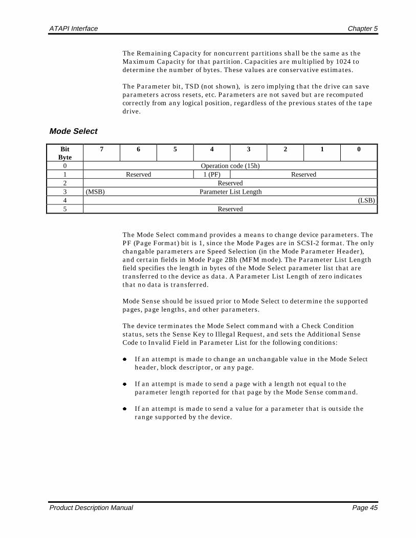
The Mode Select command provides a means to change device parameters. ThePF (Page Format) bit is 1, since the Mode Pages are in SCSI-2 format. The onlychangable parameters are Speed Selection (in the Mode Parameter Header),and certain fields in Mode Page 2Bh (MFM mode). The Parameter List Lengthfield specifies the length in bytes of the Mode Select parameter list that aretransferred to the device as data. A Parameter List Length of zero indicatesthat no data is transferred.
Mode Sense should be issued prior to Mode Select to determine the supportedpages, page lengths, and other parameters.
The device terminates the Mode Select command with a Check Conditionstatus, sets the Sense Key to Illegal Request, and sets the Additional SenseCode to Invalid Field in Parameter List for the following conditions:
z If an attempt is made to change an unchangable value in the Mode Selectheader, block descriptor, or any page.
z If an attempt is made to send a page with a length not equal to theparameter length reported for that page by the Mode Sense command.
z If an attempt is made to send a value for a parameter that is outside therange supported by the device.

Chapter 5 ATAPI Interface
Page 46 STT8000 ATAPI Minicartridge Drive
Mode Sense
BitByte
7 6 5 4 3 2 1 0
0 Operation code (1Ah)1 Reserved DBD Reserved2 00(PC) Page Code3 (MSB) Allocation Length4 (LSB)5 Reserved
The PC (Page Control) field is 00, since only current values are reported. IfDBD (Disable Block Descriptor) is set (1), then the Mode Block Descriptor is notincluded in the data returned to the host. The Allocation Length field specifiesthe number of data bytes to transfer
The following pages are supported for Mode Select and Mode Sense commands.
Page Code Description
11h Medium Partition Page
2Ah Capabilities and Mechanical Status Page
2Bh Tape Parameters Page (MFM mode)
3Fh Return All Pages
Mode Parameter Header
The following table describes the Mode Parameter header.
Byte Description Value Meaning0 Mode Data Length NN Select: Reserved
Sense: Length of Available Following Data1 Medium Type NN Tape type2 Device Specific Parameters WP,001,Speed Bit 7 = Write Protect, Bits 6-4 = 001, Bits 3-
0 = Speed Selection3 Block Descriptor Length 00/08h If 8, Block Descriptor follows
The only supported Buffered Mode (bits 6-4 of byte 2) is 001, indicating thatwrite operations are buffered. Only the Speed Selection field can be changed.
The following table defines the tape speeds supported with QIC-3095 tapes.
Speed Tape Speed Transfer Rate
0000b Automatic Automatic
0001b 46 ips 300 KBytes/sec
0010b 69 ips 450 KBytes/sec
0011b 92 ips 600 KBytes/sec

ATAPI Interface Chapter 5
Product Description Manual Page 47
Mode Block Descriptor
The Block Descriptor is returned to the MODE SENSE command unless theDBD bit in the command packet is set to one. If the Block Descriptor is not sent,the Block Descriptor Length field (in the Mode Parameter Header) is 0.
Byte Description Value Meaning4 Density Code NN Current Density5-7 Number of Blocks 000000h Zero8 Reserved 00h —9-11 Block Length 000200h Always 512 byte blocks
The Number of Blocks is 0, indicating that all blocks in the media match thisdescriptor, (the blocks are fixed 512 byte blocks).
None of the Block Descriptor parameters may be changed (Block Length isfixed).
Mode Medium Partition Page
The following table describes the Mode Medium Partition Page layout.
Byte Description Value Meaning0 Page Code 11h Medium Partition Page1 Page Length 06h 6 Bytes of Information2,3 Maximum Additional Partitions,
Additional Partitions Defined00h,00h Not Supported
4 FDP (bit 7), reserved 80h Fixed Data Partitions5 Medium Format Recognition 03h Format and Partition Recognition6,7 Reserved 00h,00h —
None of the Medium Partition Page (11h) parameters can be changed.
Mode Capabilities and Mechanical Status Page
The following table describes the Mode Capabilities and Mechanical StatusPage layout.
Byte Description Value Meaning0 Page Code 2Ah Capabilities and Mechanical Status Page1 Page Length 12h 18 Bytes of Information2,3 Reserved 00h,00h —4 SPREV (bit 5), RO (bit 0) 20h Space Reverse supported, bit 0 = Write
Protect status5 QFA (bit 5) 20h QFA supported6 ECC (bit 6) 40h ECC supported7 BLK1024 (bit 1), BLK512 (bit 0) 03h 512 byte blocks (1024 if floppy tape)8,9 Maximum Speed Supported (KBps) 600. 600 KBytes/sec Maximum10,11 Maximum Stored Defect List
Entries0000h —
12,13 Continuous Transfer Limit (blocks) 0034h 52 blocks per Read/Write command14,15 Current Speed Selected (KBps) NNNN Current transfer rate16,17 Buffer Size (in 512 bytes) 02D8h 14 frames of 52 blocks = 72818-19 Reserved 00h —

Chapter 5 ATAPI Interface
Page 48 STT8000 ATAPI Minicartridge Drive
None of the Mode Capabilities and Mechanical Status Page (2Ah) parameterscan be changed.
Mode Tape Parameters Page
Byte Description Value Meaning0 Page Code 2Bh Tape Paremeters Page1 Page Length 0Eh 14 Bytes of Information2 Density in Kilo bits per inch NN Density can imply tape format3 Reserved 00h —4 Reserved (Format Fill Byte) 00h Not used, MFM mode is read only5 BSEG 20h Number of Blocks per Segment (32)6,7 SEGTRK NNNN Number of Segments per Track8,9 TRKS NN Number of Tracks (per Tape)10 MAXSECT 80h Max MFM Sector Value (128)11 MAXCYL NN Max MFM Cylinder Value12 MAXHD NN Max MFM Head Value13,14 Reserved 0000h —15 WDAM,RM,FW (bits 7-5) 00h Not Used, MFM mode is read only
This page is used for MFM (Modified Frequency Modulation), or floppyinterface tape formats, such as 2080, 2120, TR1, TR2, TR3, etc. The drivesupports the reading of MFM tapes, but does not support write or formatoperations on MFM tapes.
The following fields are changeable: SEGTRK, TRKS, MAXCYL, and MAXHD.
Read
BitByte
7 6 5 4 3 2 1 0
0 Operation code (08h)1 Reserved 1 (Fixed)2 (MSB)3 Transfer Length4 (LSB)5 Reserved
The Transfer Length specifies the number of fixed 512 byte blocks to betransferred. A transfer length of 0 indicates that no data is to be transferred butwill initiate a read-ahead.
The DSC bit is reset (0) after this command is accepted and is set (1) when atleast 52 blocks in the buffer are available for the next READ command. Issuinga READ command when the DSC bit is reset (0) will keep the ATA bus busy(BSY = 1) while the drive is reading the required data into the buffer. Thisdelay could be more than a minute if exhaustive retries are required to read thedata.

ATAPI Interface Chapter 5
Product Description Manual Page 49
Read Position
BitByte
7 6 5 4 3 2 1 0
0 Operation code (34h)1 Reserved2 Reserved3 Reserved4 Reserved5 Reserved6 Reserved7 Reserved8 Reserved9 Reserved
The following table describes the Read Position layout.
Byte Description Value Meaning0 BOP, EOP, BPU nn 80h = Beginning of Partition
40h = End of Partition04h = Block Position Unknown
1 Partition Number 00/01h Current Partition (bit 0)2,3 Reserved 00h -4-8 First Block Location
(Host Block Location)NNNNNNNN Logical Number of next block to transfer
between host and buffer8-11 Last Block Location
(Medium BlockLocation)
NNNNNNNN* Not Supported
12 Reserved 00h —13-15 Blocks in Buffer 000000* Not Supported16-19 Bytes in Buffer 00000000* Not Supported
*These fields might appear to report the number of bytes/blocks in the buffer.However, this information is not guaranteed to be accurate. You should not relyon this information.
The only position that is guaranteed is the host logical block position. The Firstand Last Block Locations both return the same host location, and Blocks andBytes in Buffer are reported as 0.
Because Read Position is DSC restrictive on all ATAPI tape drives, it can beused to “wait” for any previous command to complete. This can be useful forapplications with ATAPI only access to determine the actual completion of acommand. Note, this will keep the ATA bus busy during the “wait”. DSC polling(to wait for DSC set) is preferred when possible.

Chapter 5 ATAPI Interface
Page 50 STT8000 ATAPI Minicartridge Drive
Request Sense
BitByte
7 6 5 4 3 2 1 0
0 Operation code (03h)1 Reserved2 Reserved3 Reserved4 Allocation Length5 Reserved
An Allocation Length value of 20 will return all Request Sense data.
The Request Sense command is always accepted, regardless of the state of theDSC bit, but the status is valid only when DSC or CHK (error) is set (1). If DSCand CHK are both reset (0), a non-error “null” status is returned. Normally, ifCHK is set, DSC is set. The only time CHK is set and DSC is reset, is duringwrites at logical end of media; DSC remains a buffer indicator, and CHK is setto indicate EOM, which is a warning, not an error.
If a command completes with a check (error) condition, the next commandissued, if not Request Sense or Inquiry, will be aborted, and a deferred errorwill be reported. If the command is Request Sense, a non-deferred error isreported. The Inquiry command does not affect status reporting.
The following table describes the REQUEST SENSE layout.
Byte Description Value Meaning0 Valid, Error Code 70h,71h 80h = Information Field Valid
+ 70h = Current Errorsor 71h = Deferred Errors
1 Reserved (Segment Number) 00 —2 Filemark, EOM, ILI, Sense Key NN 80h = Filemark
+ 40h = EOM+ 20h = ILI+ Sense Key
3-6 Information NNNNNNNN Transfer Residue or Unwritten Blocks + Filemarks
7 Additional Sense Length 0Ah 10 bytes following8-11 Command Specific Information 00h Not Supported12 Additional Sense Code (ASC) NN13 Additional Sense Code
Qualifier (ASCQ)NN
14 Field Replaceable Unit Code 00h Not Supported15 SKSV + Sense Key Specific 00h Not Supported16,17 Sense Key Specific 0000h Not Supported18,19 Pad 0000h Pad to 4-byte boundary

ATAPI Interface Chapter 5
Product Description Manual Page 51
Rewind
BitByte
7 6 5 4 3 2 1 0
0 Operation code (01h)1 Reserved2 Reserved3 Reserved4 Reserved5 Reserved
The Rewind command first ensures that all buffered write data has beentransferred to the medium, then causes the device to position to BOP of thecurrent partition.
The DSC bit is reset (0) after this command is accepted and is set (1) when thedrive is ready to write at BOP0 (or encountered a hardware error). REQUESTSENSE can then be used to verify successful command completion.
Space
BitByte
7 6 5 4 3 2 1 0
0 Operation code (11h)1 Reserved Space Code2 (MSB)3 Count4 (LSB)5 Reserved
The only Space codes that are supported are 001b (Filemarks) and 011b (End ofData on Current Partition). For Space Filemarks, negative count (2scompliment) indicates Space Filemarks Reverse.
The DSC bit is reset (0) after this command is accepted and is set (1) when thecommand is completed and the drive is ready. REQUEST SENSE can then beused to verify successful command completion.

Chapter 5 ATAPI Interface
Page 52 STT8000 ATAPI Minicartridge Drive
Test Unit Ready
BitByte
7 6 5 4 3 2 1 0
0 Operation code (00h)1 Reserved2 Reserved3 Reserved4 Reserved5 Reserved
This command can be used to determine the readiness of the device to accept amedia access command. It’s purpose is to indicate the cartridge state: nocartridge (or drive fault), cartridge becoming ready, or cartridge/drive ready.
If the drive is busy with a previous command (DSC reset), the drive will wait forthe previous operation to complete before releasing the ATA bus. On some otherATAPI tape drives, Test Unit Ready does not wait for DSC set beforecompleting, and if an application needs to “wait” for an command done via theATAPI interface, Read Position should be used instead.
Write
BitByte
7 6 5 4 3 2 1 0
0 Operation code (0Ah)1 Reserved 1 (Fixed)1 Reserved2 (MSB)3 Transfer Length4 (LSB)5 Reserved
The Transfer Length specifies the number of fixed 512 byte blocks to betransferred. A transfer length of 0 indicates that no data is to be transferredbut is used on some drives to put DSC into write buffer mode.
The DSC bit is reset (0) after this command is accepted and all data has beentransferred. This bit is set (1) when there are at least 52 empty blocks in thebuffer available for the next WRITE command. Issuing a WRITE commandwhen the DSC bit is reset (0) will keep the ATA bus busy (BSY=1) until buffer

ATAPI Interface Chapter 5
Product Description Manual Page 53
Write Filemark
BitByte
7 6 5 4 3 2 1 0
0 Operation code (10h)1 Reserved2 Reserved3 Reserved4 Reserved Count5 Reserved
After receiving this command, the device sets DSC (0) and returns completionstatus. Any data remaining in the buffer is then written to tape (flush/synchronize), and if the count is 1, a Filemark is written. In any case, an EODis then written.
The Immed bit in the command packet is ignored, and the DSC bit is reset (0)after this command is accepted. The DSC bit is set (1) after the EOD has beensuccessfully written. REQUEST SENSE can then be used to verify successfulcommand completion.
Write Buffer (Download Microcode)
BitByte
7 6 5 4 3 2 1 0
0 Operation code (3Bh)1 Reserved 101 (Mode)2 Reserved3 Reserved4 Reserved5 Reserved6 (MSB)7 Transfer Length8 (LSB)9 Reserved
The Write Buffer command is intended only to provide a method fordownloading new drive microcode (firmware) into Flash EPROM, so the onlyvalid MODE is 101 (download microcode and save). The drive must be NotReady (unloaded) for this command to be accepted, and the transfer length isset to the download file size, which is currently 0x026800. All data istransferred in one command.

Chapter 5 ATAPI Interface
Page 54 STT8000 ATAPI Minicartridge Drive
Notes

Product Description Manual Page 55
Tape Format
Introduction
The STT8000 ATAPI minicartridge drive conforms to the QIC-3095-MCrecording format standard. This format is for streaming magnetic tape in aminicartridge that is to be used for information interchange among informationprocessing systems, communication systems, and associated equipment.
This chapter provides an overview of the tape format used by the STT8000ATAPI minicartridge drive.
Tape Partitioning
The drive uses factory prewritten Travan TR-4 media. The tape is alwaysdivided into two partitions:
z Partition 1 is the directory partition and is recorded on the Directory trackonly.
z Partition 0 contains the data (tracks 1 through 71) and is recorded on alltracks except the Directory track.
Recording data at 67,733 bits per inch (BPI), the drive can store 4.0 GB on thedata partition of one 900-foot long, 0.315-inch (8.0 mm) wide Travan TR-4 tape.Using software data compression, these capabilities are typically doubled.
The recording format and partitioning support Quick File Access (QFA).
Track Positions
The centermost track is called the Directory Track and has larger guard bandson both sides of it to allow it to be written without interfering with its adjacenttracks.
Track zero is the track immediately below the Directory Track. The evennumbered tracks are positioned sequentially below track 0. Thus, track 2 isbelow track 0, and track 4 is below track 2, and so on down to track 70, which isthe closest to the reference edge of the tape. (The reference edge is the edge ofthe tape that is nearest to the baseplate of the cartridge.)
Track 1 is the track immediately below the Directory Track. The odd numberedtracks are positioned sequentially up from track 1. Thus, track 3 is above track1, and track 5 is above track 3, and so up to track 71, which is the closest to theupper edge of the tape.
6
Chapter 6 Tape Format
Page 56 STT8000 ATAPI Minicartridge Drive
Track Numbering
All even numbered tracks, and the Directory Track, are recorded in the forwarddirection (the direction from the BOT marker to the EOT marker). All oddnumbered tracks are recorded in the reverse direction (the direction from theEOT marker to the BOT marker). All even numbered tracks are located belowthe Directory Track; all odd numbered tracks are above it.
Track Format
Tracks are recorded sequentially beginning with track 0, then track 1, and soon. Before recording, data are grouped into blocks, and blocks are grouped intoframes with 64 blocks per frame.
Two numbering methods are used for blocks: physical numbering and logicalnumbering. Both numbers start from 0 at the beginning of each partition.
z Physical numbering is related directly to the recorded block on the tape.Each new block is given a unique physical number, regardless of itscontents.
z Logical numbering does not relate to the blocks physically recorded on thetape; rather, this type of numbering is the block numbering system used bythe host computer. Often the host system operates with logical blocks thatare a different size from the 512-byte blocks that are physically recorded onthe tape.
The host blocks can be larger or smaller than 512-bytes and can also befixed or variable. Fixed host blocks contain the same number of data bytesin each block. Variable host blocks may contain a different number of databytes in each block.
The format provides both a physical block number for each block recorded onthe tape and a logical block number that can span more than one physical block.These two numbers are recorded in the control field of every block.
Frames
Every track on the tape is recorded in blocks that contain 512 data bytes. Thedata bytes are 8-bit bytes, which are numbered b0 to b7 with b7 being the mostsignificant bit.
A frame is made up of 64 blocks—52 data blocks plus 12 error-correction code(ECC) blocks. Figure 6-1 illustrates the general track layout of sequentiallyrecorded frames.

Tape Format Chapter 6
Product Description Manual Page 57
Figure 6-1General Track Layout
Frame
N+1
Frame Frame Frame Frame
N N+2 N+3 N+4
Frames are numbered indirectly using the 26 most significant bits of thePhysical Block Address. Frame operation is controlled by the drive andgenerally invisible to the host. Frames are used primarily as a means to controlthe error correction operations.
Frames can be overwritten with new data frames or an end-of-data (EOD)frame. Append operations can only begin at EOD.
An underrun is not allowed in the middle of a frame, regardless of the frametype. Filler blocks can be used to complete a frame as long as they are not usedinterior to a logical block.
A frame that cannot be completed on one track is rewritten in its entirety at thebeginning of the following track. Frames are not split around corner turns.
The general frame layout—52 data blocks and 12 ECC blocks—is illustrated inFigure 6-2.
Figure 6-2General Frame Layout
DataBlock
Data Data DataBlock Block Block
0 1 2. . . . .
51
ECC ECCBlock Block. . . . .
0 11
The four types of frames are as follows:
z Data frames contain data and information blocks in addition to ECCblocks.
z The Media Header frame contains only Media Header blocks and ECCblocks. This frame is recorded as the first frame on the Directory Track.
z Track ID frames are recorded as part of the preformatting process of thecartridge. These frames are easily distinguished from other frame typesbecause they reside entirely outside of the data region of the tape.
z An EOD frame is an absolute indicator of the end of the recorded data. It isrecorded after the last frame containing host data upon terminating aWrite process.

Chapter 6 Tape Format
Page 58 STT8000 ATAPI Minicartridge Drive
Blocks
Information in the Block Control byte determines the type of block beingrecorded except for ECC blocks which are recognized by their block numbers.Also, information about the number of user data bytes available in each datablock is recorded in the Block Control byte of the block.
The Data Field of the blocks always contain 512 bytes. However, the number ofvalid data bytes in the block may be less than 512.
The seven different types of blocks are as follows:
z Data blocks contain user data. A full Data block contains 512 bytes;however, data block can contain from 1 through 511 valid data bytesdepending on the selected logical block size of the host.
z Media Header blocks contain specific host., drive, and vendorinformation as well as the Volume Directory. The first frame on theDirectory Track is teh Media Header Frame. This frame contains 52 MediaHeader blocks (plus the normal 12 ECC blocks).
z Information blocks—Filemark blocks, Setmark blocks, and Cancelmarkblocks—contain specific types of information. Filemark blocks are physicalblocks written to tape in response to a host WRITE FILEMARKS command.Setmark blocks are physical blocks written to tape in response to a hostWRITE SETMARKS command. Cancelmark blocks are physical blockswritten to tape under firmware control.
z Filler blocks contain no valid information in the data area. These blocksare used to fill incomplete frames.
z EOD blocks are absolute indicators of the end of recorded data.
z ECC blocks contain error correction parity bytes that are used toensuredata integrity during read operations.
z Track ID blocks are recorded as part of the preformatting process of thecartridge.
Tape Reference Servo Pattern
To increase track density, a track servo reference pattern is prerecorded on thetape at the factory. The pattern is recorded referenced to servo patterns in theregion between the beginning-of-tape (BOT) hole and the load point market(LP) hole. The same pattern is recorded between the end-of-tape (EOT) hole andthe early warning (EW) hole. The servo pattern is written across the entirewidth of the tape.
Tape Format Chapter 6
Product Description Manual Page 59
Write Equalization
The drive uses the technique of write equalization. RLL encoding has a 4:1ratio in the minimum and maximum spacing between flux transitions. Writeequalization inserts short pulses in the write current to break up the longspacing intervals. These pulses are too short to be detected in the read processbut result in significant improvement in read-back resolution.
On 900 Oersted media, write equalization provides the benefit of compatibilitywith Magneto-Resistive (MR) heads. MR heads are prone to saturation by lowfrequency flux with high energy content. Equalization redistributes this energyto higher frequencies and eliminates the problem.
Randomization
To reduce problems resulting from long strings of repetitive data with a badpeak shift or amplitude characteristics, a data randomizer algorithm is used onall bytes in the data and control area of each block. This randomizing takesplace prior to the encoding of the data.

Chapter 6 Tape Format
Page 60 STT8000 ATAPI Minicartridge Drive
Notes

Product Description Manual Page 61
Theory of Operations
Overview
The STT8000 ATAPI minicartridge drive is a low-cost, high-performance D2000minicartridge tape drive that is ideal for stand-alone users or small networkcomputer systems. With capacities of 4.0 GB to 8.0 GB dependent upon mediaand data compression, this drive offers quick, efficient backup and restoreoperations. Its unique FastSenseTM feature automatically selects theappropriate transfer rate—600, 450, or 300 kb/sec—based on the speed of theoperating system.
The STT8000 ATAPI minicartridge drive is based on proven Seagate designs,Seagate firmware, and the latest technology. This drive uses secondgeneration, custom LSIs for efficient circuit layout and increased reliabilitywith low power consumption. The drive also uses flash EEPROM devices foreasy firmware upgrades.
This chapter describes the drive in more detail and explains implementationspecific information.
Block Diagrams
The electronics of the STT8000 ATAPI minicartridge drive are laid out on onemain printed circuit board (PCB).
Figure 7-1 is a simplified block diagram of the drive.
Understanding the Drive
This section generally describes the hardware design features of the STT8000ATAPI minicartridge drive. You may want to refer to the block diagramsreferenced previously as you read this information.
7

Chapter 7 Theory of Operations
Page 62 STT8000 ATAPI Minicartridge Drive
Figure 7-1Simplified Block Diagram
FLASHEPROM
DRAMBUFFER
HEADSTEPPER
DRIVEMOTOR
IDECONTROLLER
CONTROLLOGIC
TAPEHEAD
WRITEDRIVER
READCHANNEL
MICRO-PROCESSOR
SYSTEMCLOCK
Table 7-1Clock Frequencies used by the STT8000 Drive
VCO Frequencies—All Derived from System Clock (42 MHz Crystal Oscillator)
FundamentalFrequency
28 MHz 28 MHz 28 MHz 24.89 MHz
Channel Frequency 9.33 MHz 7.00 MHz 4.667 MHz 3.11 MHz

Theory of Operations Chapter 7
Product Description Manual Page 63
Mechanics
The mechanical package for the STT8000 ATAPI minicartridge drive wasdesigned to provide you with all the advantages of easy cartridge loading andunloading while maintaining the positioning accuracy necessary for high-density data recording. The orientation of the cartridge is the same as themajority of QIC minicartridge drives in the field.
Cartridge Load Mechanism
The cartridge is inserted in the drive by sliding it through the aperture in thebezel and into a tray mechanism. When fully inserted the back portion of thecartridge protrudes about 3/4-inch from the aperture. A switch is actuated atthis point that causes a microprocessor to complete the loading operation.
When the tape is in motion, the amber LED on the front panel flashes. TheLED is not lit when the tape is positioned at BOT.
Capstan Drive Motor Assembly
In the STT8000 ATAPI minicartridge drive, the cartridge is driven by thecapstan/belt motor assembly, which is on a linear slide. The cartridge is loadedagainst the cartridge drive roller which exerts a net radial dynamic force of 18to 26 ounces. The motor is a brushless DC drive motor with integral capstanwhich is designed to provide maximum reliability.
The motor operates from the 12V nominal supply and moves the tape at speedsfrom 35 to 100 inches per second (IPS).
Chassis
The drive mechanism is mounted in a molded frame that provides the mountingholes for the industry standard 3.5-inch by one inch form factor. A 5.25-inchmounting kit is an available option. The bezel is a simple snap-on design that isavailable in several standard and custom colors. The round, front-panel LED isamber and indicates tape activity.
Control Circuits
The control logic module shown in Figure 7-1 includes a buffer manager tohandle data movement between the controller, the buffer, and the tapeformatter. This module also includes logic to perform ECC and CRC generationand testing, WRITE/READ data formatting, head stepper control, and drivemotor control.
The microprocessor directs all functions performed by the control logic. Theinstructions are read from a flash EEPROM, which can be updated with newfirmware through a specially written tape cartridge.

Chapter 7 Theory of Operations
Page 64 STT8000 ATAPI Minicartridge Drive
The 512-KB DRAM data buffer allows the drive to maintain streaming whenthe host cannot provide data continuously at the tape streaming rate.
The write driver receives data from the write formatter and generates writecurrent, causing data to be written on tape by the tape head.
The read channel amplifies and conditions the signal from the tape head andpasses it back to the read formatter.
The head stepper and drive motor both receive current from the control logic tocontrol the stepping of the head from track to track and to move the tapeforward and back across the tape head.
Head Design
The recording/playback head is a state-of-the art, thin-film design—a thin-filminductive write head paired with an advanced magneto-resistive read head.This head design provides the drive with exceptional performance andreliability. The material composition of the head also results in exceptionalwear characteristics, resulting in stable performance throughout the life of thedrive.
Flash EEPROM
Because the drive uses flash EEPROM (electronically erasable, programmableread-only memory), the drive firmware can be easily upgraded when newrevisions of the firmware are released. The circuitry includes 128 KB of flashEEPROM.
You can load new firmware by using a specially encoded firmware upgradecartridge.
Refer to chapter 4 for information about loading new firmware using a Seagatefirmware upgrade cartridge.
Sensors and Switches
A number of mechanical and optical sensors and switches are integrated in thedrive design. The Cartridge In switch detects when a cartridge is fully loadedand positioned against the A-plane datum of the cartridge. The Unsafe switchsenses the position of the SAFE indicator on the cartridge and disables writingof write-protected (SAFE) cartridges.
The Head-Position Sensor is an electro-optical assembly (LED andphototransistor) to determine the approximate head position.
The drive has an electro-optical sensor assembly comprised of a solid-state lightsource (LED) and a photosensor (phototransistor) that sense the beginning-of-tape (BOT), end-of-tape (EOT), load point, and early warning holes of thecartridge.
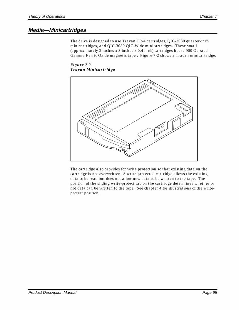
Theory of Operations Chapter 7
Product Description Manual Page 65
Media—Minicartridges
The drive is designed to use Travan TR-4 cartridges, QIC-3080 quarter-inchminicartridges, and QIC-3080 QIC-Wide minicartridges. These small(approximately 2 inches x 3 inches x 0.4 inch) cartridges house 900 OerstedGamma Ferric Oxide magnetic tape . Figure 7-2 shows a Travan minicartridge.
Figure 7-2Travan Minicartridge
The cartridge also provides for write protection so that existing data on thecartridge is not overwritten. A write-protected cartridge allows the existingdata to be read but does not allow new data to be written to the tape. Theposition of the sliding write-protect tab on the cartridge determines whether ornot data can be written to the tape. See chapter 4 for illustrations of the write-protect position.

Chapter 7 Theory of Operations
Page 66 STT8000 ATAPI Minicartridge Drive
NOTES

Product Description Manual Page 67
Maintenance, Troubleshooting, and Reliability
Maintenance
Minimal maintenance is needed to ensure that your STT8000 ATAPIminicartridge drive operates at peak condition. This section explains how tocare for tape cartridges and how to clean the drive head.
Caring for Tape Cartridges
Although minicartridges are ruggedly built, they must be handled with care topreserve the data that they contain. The following points are guidelines forstoring and using minicartridges.
z Do not open the tape access door of the cartridge or touch the tape itself.One fingerprint can prevent the drive from reading the tape.
z Keep the cartridge away from sources of electromagnetic fields, such astelephones, dictation equipment, mechanical or printing calculators,motors, and bulk erasers. Do not lay cartridges on the computer monitor oron the base unit of the computer.
z Keep the cartridge away from direct sunlight and heat sources, such asradiators or warm air ducts.
z Keep the cartridge free of moisture. Do not wet or submerge a cartridge inany liquid.
z Do not expose the cartridge to temperature extremes. Allow the cartridgeto assume room temperature slowly.
z Retensioning the tape cartridge is always recommended for optimalperformance, particularly after exposure of the cartridge to temperaturechanges or shock. Retensioning restores the proper tape tension to themedia.
Cleaning the Drive Read/Write Head
To properly maintain the tape drive, you should periodically clean theread/write head. No other periodic maintenance is required.
8

Chapter 8 Maintenance, Troubleshooting, and Reliability
Page 68 STT8000 ATAPI Minicartridge Drive
Follow these guidelines to help ensure that your drive provides long, reliableservice:
z Operate the drive in a clean, dust-free environment.
z Never apply a lubricant to the drive.
z Clean the tape drive head every month or after each 8 hours of continuousread/write operations.
For new cartridges, clean the head after two hours of tape movement.
You can clean the drive head by one of two methods: you can use the Seagateapproved 3M DC2000 cleaning cartridge DC051111 (12947), Seagate P/N10001794-001, which is available through Seagate Express 1-800-531-0968, oryou can manually clean the drive head. To manually clean the drive head,follow these steps.
1. Moisten a clean, lint-free swab in 90% isopropyl alcohol so that it is wet butnot dripping. (Never use a dry swab.)
2. Hold the drive access door open and wipe the head gently using a side-to-side motion. The upright rectangle with the stripe in Figure 8-1 is thehead.
Figure 8-1The Drive Head
HEAD
3. Allow the drive to dry for 3 minutes before using.
Troubleshooting
If you experience problems after you install the drive, take the following actionsto try to solve the problems.
z Check that the I/O address and the IRQ setting of the ATAPI card matchesthe setup information in the Seagate Backup Exec Software. Review the
Maintenance, Troubleshooting, and Reliability Chapter 8
Product Description Manual Page 69
installation manual supplied with that product to be sure the settings areappropriate.
z Check that all connections are secure.
z Check the configuration of the card and drive to be sure that the settingsare correct.
z Check to be sure that the ATAPI adapter card is firmly seated in theconnector.
z Ensure that no other peripherals are attached to the ATAPI adapter cardexcept the Seagate tape drive.
If a power interruption occurs during a backup or restore operation, start overwhen the power is restored. If the drive appears to fail during a backup orrestore operation, try the following steps:
1. Remove and replace the cartridge and try again. Make sure you are usingthe correct type of tape cartridge.
2. Turn off all power to the computer and drive. Wait for the computer topower down and then start over.
3. Try a different tape—preferably one that has never been used.
4. Check all cable connections for proper contact.
5. Clean the tape drive head as previously instructed. Then try the operationagain.
6. Check to be sure that the adapter card is firmly seated in the connector.
7. Verify that the I/O address and IRQ settings of the adapter match the setupin the Seagate Backup Exec software.
If problems persist, contact your tape drive supplier or Seagate technicalsupport at
(800) SEAGATE US and Canada 732-4283
44-294-315333 Outside US and Canada
Seagate Web Site http://www.Seagate.com
Seagate BBS (408) 456-4415
Be sure that you have the documentation for your computer and all installeddevices before you call technical support.

Chapter 8 Maintenance, Troubleshooting, and Reliability
Page 70 STT8000 ATAPI Minicartridge Drive
Reliability
The STT8000 ATAPI minicartridge drive is designed for maximum reliabilityand data integrity. The following table summarizes the reliability specifications.
Feature Specification
Nonrecoverable errorrate
< 1 in 1015 bits
Error recovery andcontrol
Reed-Solomon Error CorrectionCode techniquesError monitoring and reporting(Error Log)Media prewrittenRetry on readData randomization
Mean-Time-Between-Failures (MTBF)
More than 200,000 hours
Mean-Time-To-Repair(MTTR)
Less than 0.33 hour
Mean-Time-Between Failures
The Mean-Time-Between Failures (MTBF) is greater than 200,000 hours. Thisspecification includes all power-on and operational time but excludesmaintenance periods. Operational time is assumed to be 20% of the power-ontime. Operational time is the time the tape is loaded.
Note: Seagate does not warrant the stated MTBF as representative of anyparticular unit installed for customer use. The failure rate quoted here isderived from a large database of test samples. Actual rates may vary fromunit to unit.
Mean-Time-To-Repair
The Mean-Time-To-Repair (MTTR) is the average time required by as qualifiedservice technician to diagnose a defective drive and install a replacement drive.The MTTR for the drive is less than 0.33 hour (20 minutes).
The STT8000 ATAPI minicartridge drive is a field replaceable unit. If aproblem occurs with a subassembly or component in the drive, the entire unitshould be replaced. The faulty drive should be returned to the factory in itsoriginal packaging. Contact your distributer, dealer, your computer systemcompany, or your Seagate sales representative to arrange the return.

Product Description Manual Page 71
Glossary
ATA Packet Interface—The interface providing for communications between the host computer andthe drive (standard QIC-157).
Azimuth—The angular deviation, in minutes of arc, of the mean flux transition line from the linenormal to the tape reference edge.
Backup—Copy of a file or collection of files on fixed disk, diskette, or tape. Ensures against data loss.
Beginning of Media (BOM)—Equal to the physical beginning of the tape.
Beginning of Tape (BOT)—Equal to the logical beginning of the tape.
Bezel—Front panel of a drive.
Bit—A single digit in the binary numbering system.
Bit Error Rate—The number of errors divided by the total number of bits written or read.
Block—A group of 512 consecutive data bytes plus additional control bytes recorded as a unit.
BOP—Beginning of Partition. The position at the beginning of the permissible recording region of apartition.
BOT marker—The beginning of tape (BOT) marker is a set of two holes punched side by side in thetape.
Byte—A group of 8 binary bits operated on as a unit.
Cancelmark—A "negative" Filemark or Setmark. When a Cancelmark follows as the first block in thenext frame after a Filemark or Setmark, the drive when reading the tape will logically ignore theCancelmark and the Filemark or Setmark it cancels.
Cartridge—An enclosure containing magnetic tape wound on two coplanar hubs.
Control field—A group of 8 bytes recorded before the data area in each block, continaing informationabout clock address, track address, and block type.
Cyclic Redundancy Check (CRC)—A group of 2 bytes recorded at the end of each block of data forthe purpose of error detection.
Data block—A block containing user valid data in its data field
Data Compression—The process of removing redundant data from a data stream before recordingthe data to tape. Compressed data requires less storage space than uncompressed data.
A

Appendix A Glossary
Page 72 STT8000 ATAPI Minicartridge Drive
Data Density—The number of single-byte characters stored per unit length of track. Usuallyexpressed as bits-per-inch (bpi).
Decompression—The process of restoring compressed data to its original state.
Dew—Collection of moisture in a tape drive.
Directory track—The track at the centerline of the tape, identified as track 254 by its Track IDframe.
Disk Drive—A peripheral storage device that rotates the disk, writes data onto it, and reads datafrom it as instructed by a program.
ECC—(Error Correction Code) Special drive generated information that can be used to correct badblocks.
ECC block—A block containing drive-generated ECC data in its data field and part of control field.
Encoding—A method whereby a group of data bits is translated into a group of recording bits.
End-of-Data (EOD)—Indicates the point where the host stopped writing data to the tape.
End-of-Media (EOM)—Equal to the physical end of tape.
End-of-Partition (EOP)—The position at the end of the permissible recording area of a partition.
End of Tape (EOT)—Equal to the logical end of the tape.
Error Correction Codes (ECC)—nformation written on tape during the recording operation thatcan later be used to reconstruct errors during the data reading operation.
Early Warning (EW)—The early warning marker is a single hole punched in the tape to indicate theapproaching end of the usable recording area in the forward direction.
File—A logical unit of information.
Filler block—A block containing no valid informaiton in its data field.
Fixed Disk—A non-removable hard disk. All data must be transferred to and from the disk via thecomputer.
Frame—A group of 64 blocks forming a complete logical group.
Full-high (or full-height)—Usually refers to a tape drive fitting in a vertical space of 3-1/2 inches.
Half-high (or half-height)—Refers to the size of tape drive occupying a vertical space of about 1-1/2inches.
Head Clog—Particles from the tape or from outside the drive adhere to the head gap on a read orwrite head and obstruct the reading or writing of data.
Interleaving—The process of shuffling the order of data blocks before writing them to tape so theconsecutive bytes are not recorded physically adjacent.
Glossary Appendix A
Product Description Manual Page 73
Magnetic Tape—A tape that accepts and retains magnetic signals intended for input, output, andstorage of data for information processing.
Media Header block—A unique block identifying the type of format being recorded.
Noise—A disturbance of the signal caused by the read channel, write channel, head/tape interaction,or conducted or radiated sources.
Randomizing—A recoding of data symbols before they are written to tape in order to provide aconsistently uniform RF envelope level.
RLL (Run Length Limited)—A data encoding method where data bits are encoded so that certaincontraints are emt with regard to the maxmum and minimum distances between flux transitions.
Serpentine—A recording method in which tracks are laid down sequentially, and the tape is notrewound at the end of a track. This recording method exploits the bidirectional capabilities of thecartridge.
Streaming—A method of recording on magnetic tape that maintains continuous tape motion withoutthe requirement to start and stop within an interblock gap.
Tape Drive—A peripheral storage device that records data onto removable tape cartridges. Used toback up a disk drive. (See also Disk Drive.)
Track—A longitudinal area on the tape along which magnetic signals can be serially recorded.
Track ID block—A block recorded in the Load Point and Early Warning regions to designate thetrack number.
Uncorrected Bit Error Rate—The probability of a bit being in error, without using any errorcorrection techniques.
Underrun—A condition developed when the host transmits or receives data at a rate less thanrequired by the device for streaming operation.

Appendix A Glossary
Page 74 STT8000 ATAPI Minicartridge Drive
Notes

Product Description Manual Page 75
Acronyms and Measurements
Acronyms and Abbreviations
Acronym MeaningANSI American National Standards InstituteBIOS Basic Input Output SystemBOM Beginning of MediaBOT Beginning OF TapeBPI Bits Per InchCD Compact DiscCMOS Complementary Metal-Oxide
SemiconductorCSA Canadian Standard AssociationDMA Direct Memory AccessECC Error Correction CodeECMA European Computer Manufacturers
AssociationEEPROM Electronically Eraseable,
Programmable Read-Only MemoryEOD End of DataEOM End of MediaEOT End Of TapeFCC Federal Communications CommissionFTPI Flux Transitions Per InchIDE Intelligent Drive ElectronicsIEC International Electrotechnical
CommissionIPS Inches Per SecondLED Light Emitting DiodeLSI Large Scale IntegrationMTBF Mean Times Between FailuresMTTR Mean Time To RepairOEM Original Equipment ManufacturerPCB Printed Circuit BoardQIC Quarter Inch Cartridge Drive
Standards, IncorporatedRAM Random Access MemoryRLL Run Length LimitedSCSI Small Computer System InterfaceUL Underwriters' Laboratories, Inc.VDC Volts Direct CurrentVDE Verband Deutscher Electrotechniker
B

Appendix B Acronyms and Measurements
Page 76 STT8000 ATAPI Minicartridge Drive
Measurements
Measure MeaningA AmpC Celsius or Centigradecm centimeterdBa decibels, A-weighted sound power
reference one picowattF Fahrenheitft foot or feetg acceleration of a free-falling body; equal
to 32.17 feet per second2
GB gigabyteHz Hertzin. inchk kiloKB kilobytekg kilogramKHz kilohertzlb(s) pound(s)m meterM megaMbits megabitsMB megabyteMHz megaHertzmin minutemm millimeterms millisecondRPM revolutions per minuteV VoltW Watt