Embed Size (px)
Citation preview
SEALING FARM PONDS IN-- P
Ozark Highlands * ?
Central Mississippi Valley Wooded Slopes*-
Deep Loess Hills
Jur 1963 ARS 41-78
Agricultural Research Service
UNITED STATES DEPARTMENT OF AGRICULTURE
- ' . ,I. . 4: CONTENTP p ~ . ~ & . $'.\ 4 + I ~ ~ ~ , ! ' ~ - ~ , J 7 -3 t v ~ ' r " . 7 . - i ' *
n.- 4 : r; I
Principles of sealing farm poncis. ......................... Study of problem soils used for pond construction ..............
aoil descriptions ....................................... ....................... Laboratory studies of soil compaction
Prepared by
....................... Effect of soil compaction on hydraulic conductivity.
Tests with barnyard manure. ...................................... - 101 i t , .- . L 4
Tests with polyphosphates and silicates ................................ ........................... Tests with emulsions .............. - - 11
............................................ Laboratory model studies 11 -, I.., ,,.,rt..,L .:+$ y stioV i ~ q i a r i z z i m "- u \ " & . ............................................ Procedure.... . . . 12
F i e l d t e s t s . . . . . . . . . . . . . . . . . .................................... l5 I Procedure...... .............................................
l5 I ................................................ Observations. l7 i
................................................. ~ i t e r a t u r e cited. 20,
Soil and Water Conservation Research Division Agricultural Research Service U.S. Department of Agriculture
in cooperation with 7'f,
QT-c? 1 I + Missouri Agricultural Experiment Station . e.- J~,-.'. d' . - ,9 > # l!3''.@?~3hg& and
,J 2- . - --- A
- - - - ~ L I L I J I J > . B ~ A ' a i l c o n s e n a t i o n s e M c e - C A W iiilwo b r a , r r + t ? ?
&a*
. r c: r I l 8
r l ~ [ ~ l w 1 SEALING FARM PONDS IN OZARK HIGHLANDS, QF+~W
r$ef r=t?~li jLrc%rr.jp: CENTRAL MISSISSIPPI VALLEY WOODEP,#Q!ES, ,,,,, ,,, : .uw 2) SIP , ANDDEEPLC--- HILLS1 l - . k - l f l L f - - 5 ~ u n ~ : i ~ 7
Properly constructed and sealed farm ponds a re water-saving structures. They will reduce peak runoff and drainage-channel erosion during wet periods and provide water for farm animals and irrigation during dry seasons. Leaking ponds lose much of their value, since they cannot be relied upon to supply storage when it is needed. Ponds that leak so rapidly a s to be dry most of the time represent serious losses in land and construction cqsts. . - ,. -.- - -.- - . -
Id Ac,,,ha t% !€E-;
Excessive seepage from ponds is a serious problem in many areas of the Midwest. A survey of farm ponds in Dade County, Mo., made in November 1959 by the Soil Conservation Service, revealed 75 to 80 seriously leaking o r dry ponds in that county and 750 to 1,000 such ponds in southwestern Missouri. Most of these ponds were excavated in soils derived from Mississippian limestones and shales. Leaking and dry ponds occurred most frequently where they were excavated in soils classified a s being included in the Newtonia, Baxter, Eldon, Eldorado, Craig, and Gasconade series. Most of the dry ponds were constructed according to current recommendations, which specify a depth of at least 8 feet. These a r e generally excavated deeper than the older reservoirs, which had fewer failures. The older shallow structures were less apt to expose the highly aggregated red clay subsoilor cherty gravel layers in the deep subsoil. Also, many older ponds were not fenced and farm animals were allowed to trample in them. This trampling may have improved sealing of the pond bottom. . 1 L Tm,-!~t.~ B
r t ' . ~ m .>$:I
Depth is essential for a dependable water supply. High evaporation losses during droughts will tend to nullify the value of a shallow pond, since it will contain water only when the need is not great. A shallow pond may be littlemore than a source of mosquito infestation during normal periods of rainfall and a dry basin during dry seasons when water is needed.
I . 4, *l*>:i-i- The problem of rapid pond seepage is not confined to the Ozark Highlands. Some leaking
ponds were excavated in soils of the Deep Loess Hills--the Menfro, Winfield, and Memphis-- soils of the central Mississippi Valley wooded slopes, and a few in the Shelby, Grundy, and Sharpsburg of the Heavy Till Plains. Profile descriptions of representative soils of these areas a r e given elsewhere (7, B).S
tJaor-- + ,.-:, . PRINCIPLES OF SEALING FARM PONDS
Basic principles of pond construction and sealing have been presented by Holtan @, 6). If an impervious layer is beneath the bottom of the pond, a good seal may be achieved by placing an impervious core in the fill, o r by spreading and compacting a surface blanket of impervious material on the face of the fill. The core o r blanket must be keyed into the impervious layer or,
i b . 4d1 o 31(6 3d V.
. A . -1, A I L u ' L - . . U - . & I
1 Contribution from the Soil and Water lservation Research Division, Agricultural Research Service, USDA, !! cooperation with the Missouri Agricultural Experiment Stati md the Soil Conservation Service, USDA.
2 Soil Scientist and Agricultural Engineer. Soil and Water -_.servation Research Division, at Columbia, Mis- wu%
a Underscored numbers in parentheses refer fo Literatare Cited at ead of pub3icatim ~ m a m t
where such a ,$!I%?@-* 'Be &&.%WU&W ?jf a compacted impervious blanket covering the pond bottom and the sides extending above the high water level. To prevent excesrsive fleepage or blowout Qailu~efi, the sealing layer must have beneath it o r within its depth, sufficient strength to support the head of water above it. Holtan's tests (a with soils in Virginia in which ponds were constructed showed that compacted blankets of sandy loam soil materials should be most satisfactory. A good combination of strength and impermeability could be expected from about 1 foot of compacted sandy loam. He suggested that ideal material should have from 70 to as high a s 95 percent of sharp sand, and from 5 to 30 percent clay with silt as needed to improve the gradation of particle sizes. Compacting the materi@-ptimum m~~&ture content imp^^ s@rengt.@ a-eal. , I . . . , , : , . , , I tXl !; - 9 : = _. <??Y 5 r .~(+i ,17,b.7~ i ., - , . .. . 7~ ,I&, . I * - , :
,..rI. :Puddling hcreased @gxifeal,&s @ten reduced the+@rength5HT&e material a@ &creased the tendemy for blo~o~rfailur~~1Additit@a colloidal clay suchtm, bentonite increased the seal Qf sands, but excessive amounts reduced the soil strength. Also, bentonite acted a s a dispersing ;in clays of & , a m * t * a % t h a ~ & y iwimvkgtthe sea4Jwme&cins the strength;, i ,, .- . 3 . r , r , -: *,( I I:! . : ,, )VT. . !f?ij.-.~](y), 7 ' ' : - ! . - fh 5 , r i &-ilf.+i ' ,-. [I,., I > 4 . l a, L. r~ ? j ,-
, 7 ' 4 - r - 'I&&& @&W a d d i t i v ~ , bee&,$psted @~rsealing farm ponds and c a n a ~ , a , ,b. &mq treatment benefits, &mation of the effects was uncertain. 7 iq 2- 3j , T 1
, -,i i - ~ f , ; f - - ., ' . 1 , , . . $ 1 , . . ' - V;
t . ?.- - m-le soil aggregation~:rssponsible for high seepage, it may be possible to improw %-d seal by dispersing some!304~4he material= *+ &log the soil voids in deeper lying layers. with clay. Observation indicated that the trampling of animals will reduce seepage, probably through puddling and dispersing a s well a s by compaction of the soil aggregates so a s to form a sealed layer below the zone of disturbance. Recent- tests with tripolyphosphates (1, _2), which have a dispersing effect on sesquioxide-bond* aggregatmt-\Wicate these and similar chemicals may be us'ed to improve pond sealing.-whatever method is used, it will be effective only if the pores are sufficiently fine beneath the disturbed o r dispersed zone to entrap the fine particlea, ,a& if fhe EKJA bed has sufficient ,c&@,apd st;reRgtb to &made reg&Wce to blowout failures. r - ,I . : 7 : ; ,?; , , - - - , t - I .,-, ,. I ,I . ,
3.3. 9 , 2, 1 j ' t , 017 f r . h j ~ .:I ,!:. 7 f : : 1 t ..L> 11 :- I ? , ) .
There are related to sealing ponds other than reducing seepage. With some chemical treatments, contamination -af the water may make it unfit for irrigation or use by animals. Dia%.rs-& clay o r other colloids in the water,.may- reduce the value of the pond for stock consumption- p. recreational purposes. Dispersion, ampling ling of animals o r other means, may be e~pe~t&r@'-increase erosion of the soil at the water line, unless this zone is protected by riprapping o r other means. . - I ; . L - . I ~ ~ nz .L.S .. .
STUDY OF PROBLEM SU-ED FOR POND CQNSTRUCTION
Soil Descriptions - . , I -.Grs,i pr !Ia- - ! t ' + 1 , . I ; ? . ~ -. 4 : 2 q >;?.,to
; y ? #b! L - . ( 1 -2 1 1 , 4 1 % A <l -,:J iri , I ~ : ~ L . ., 1 1 1 ~ <ir . { I . - ,do:J. ,.!I~!
orrThe surface soil layer of the Ozark Highlands is usually silt loam. It can be compacted to , &&h bulk density; however, it is often "spongy" and permeable after compaction. This may be due to the presence of clay aggregates. The subsoil layers a re high in chert, which is intermixed .with highly stable aggregated red clay (fig. 1). In some instances, thick layers
r - L, ,I-e-. u- vss of chert-free red clay occur in the upper subsoil. This material is rapidly permeable, owing to its well-developed structure and stable aggregation. Layers of fragmental, porous chert relatively free of fine material also occur. Exposure of either red clay o r cherty material in the pond construction will result in rapid seepage loss. :Is. --). 71 . .J ~s-.. <-.-I 3 ' :. 529Ll71~~.
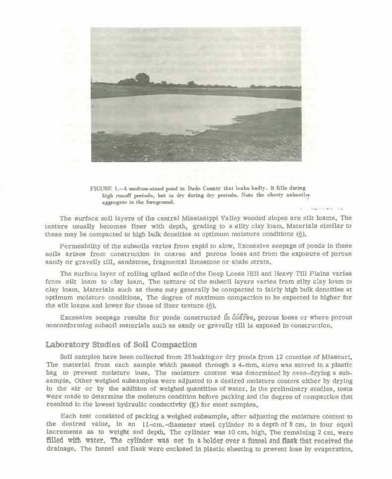
FIGURE 1.-A medimn-sieed pond in Dade Couuty that leaks badly. It fills during high runoff periods, bur is dry during dry periods. Note the cherty snbso i l~ .. aggregate in the f u e g d .
- - - - - -
The surface soil layers of the central Mississippi Valley wooded slopes a re silt hams. The texture usually becomes finer with depth, grading to a silty clay loam. Materials similar to these may be compacted to high bulk densities at optimum moisture conditions (6).
Permeability of the subsoils varies from rapid to slow. Excessive seepage of ponds in these soils arises from construction in coarse and porous loess and from the exposure of porous sandy o r gravelly till, sandstone, fragmental limestone o r shale strata.
The surface layer of rolling upland soils of the Deep Loess Hill and Heavy Till Plains varies from silt loam to clay loam. The texture of the subsoil layers varies from silty clay loam to clay loam. Materials such as these may generally be compacted to fairly high bulk densities at optimum moisture conditions. The degree of maximum compaction to be expected is higher for the silt barns and lower for those of finer texture (6).
L ,-A+.
Excessive seepage results for ponds constructed fn warfie, porous loess o r where porous nonconforming subsoil materials such as sandy o r gravelly till is exposed in construction.
Laboratory Studies of Soil Compaction Soil samples have been collected from 25leakingor dry ponds from 12 counties of Missouri.
The material from each sample which passed through a 4-mm. sieve was stored in a plastic bag to prevent moisture loss. The moisture content was determined by oven-drying a sub- sample. Other weighed subsamples were adjusted to a desired moisture content either by drying in the a i r o r by the addition of weighed quantities of water. In the preliminary studies, tests were made to determine the moisture condition before packing and the degree of compaction that resulted in the lowest hydraulic conductivity (IC) for most samples.
Each test consisted of packing a weighed subsample, after adjusting the moisture c6ntent to the desired value, in an 11-cm.-diameter steel cylfnder to a depth of 8 cm. in four equal increments as to weight and depth. The cylinder was 10 cm. high. The remaining 2 cm. were m~ with water. The i y ~ f n d e r -8 set in it holder aver a -el and ~t received the drainage. The funnel and flask were enclosed in plastic sheeting to prevent loss by evaporation.
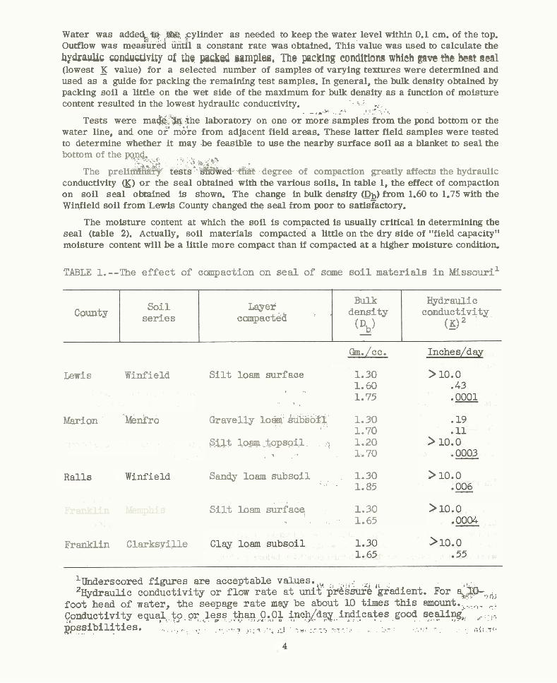
Water was adde% @y I$&. ~ y l i n d e r a s needed to keep the water level within 0.1 cm. of the top. Outflow was measurbd until a constant rate was obtained. This value was used to calculate the ByQrWc coWUwity of the pixksl aamplea, The packing eondltions which gave the best seal (lowest _K value) for a selected number of samples of varying textures were determined and used as a guide for packing the remaining test samples. In general, the bulk density obtained by packing soil a little on the wet side of the maximum for bulk density a s a function of moisture content resulted in the lowest hydraulic conductivity. *-
. - ,-2- : 3 , r L 1,
Tests were ma&'& *he laboratory on one o r more samples fib* the pond bottom o r the water line, and one or' m&e from adjacent field areas. These latter field samples were tested to determine whether i t may be feasible to use the nearby surface soil a s a blanket to seal the bottom of the wq. +-.--*f: . - 7 . * s--'&%
The preli&$+ j - - a& degree of compaction greatly affects the hydraulic
conductivity g) o r the seal obtained with the various soils. In table 1, the effect of compaction on soil seal obtained is shown. The change in bulk density (Db) from 1.60 to 1.75 with the Winfield soil from Lewis County changed the seal from poor to satisFactory.
The moisture content at which the soil is compacted is usually critical in determining the seal (table 2). Actually, soil materials compacted a little on the dry side of "field capacity" moisture content will be a little more compact than if compacted at a higher moisture condition.
TABLE 1. --The effect of compaction on seal of some s o i l materials i n Missouri1
Lewis Winfield
Marion -&n?ro
Caunty
, I , "
Franklin kernphis - *~
Bulk density (Db) -
Fraaklin Clarksyille
W r a u l i c canductivitg_
(g)2 Soil
series
Gm./cc.
S i l t loam surface 1.30 + .. 1.60
I ' I
1.75
Layer compacted - '
Gravelly l o w kub50fl' - - 1.30 1 . ' 1.70
silt lo-arp ..tgpsoil 3 1.20 4 - ) - 1.70
Sandy loam subsoil 1.30 , .
' 1.85
silt loam &.rfacq 1.30 1.65
'Underscored figures are acceptable values. ,, 'JiIydraulic conductivity or flow ra te a t unit p&&~ '3adient. For a;%,,,
foot head of water, the seepage ra te may be about 10 times this amount.*, ,,_ ,:, Cpnductivity eq~a;~, t p , or Je$s , thq ,$ i n c g d a ~ , , . . indicates . . good seali%, -, .- .,- L r . ,.. gpssibi l i t ies . , , , + , - ,t,? ., LI -yl,-. 7> -,-, , . -,- , + , i i ~ 7 '*
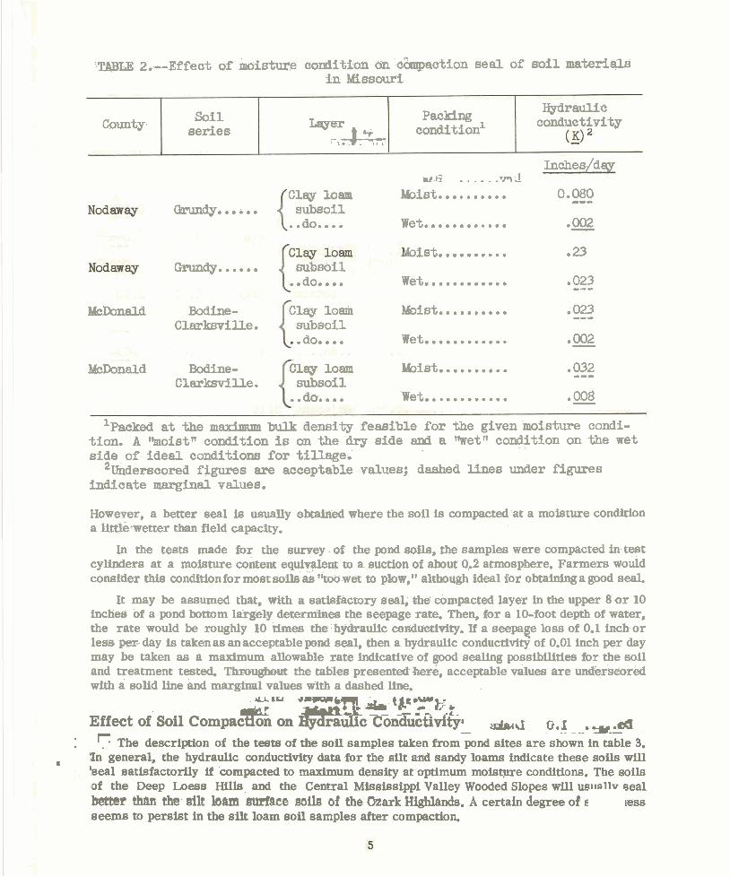
:TABLE 2.--Effect of moisture condition an cbqpaet3on seal of so i l materials: i n Missouri
........ bist.. .23 Gmdy..oao. subsoil
..do.. .. Wet............ .023 --- k h n a l d Ebdhe- Clay 10am bbEli~t.......... ,023 ---
Clmksville . subsoil .do.... Wet............ .=
Hydraulic c0ndtlctiPity
l&Donald Bodine- Moist.......... .032 --- Clarksville. subsoil
..do.. .. Wet............ .008 -
1nche s/day ........ ..md ......... Clay loam kist. 0.080 ---
Grmdy...... subsoil .do.. Wet............ . .. 0002 -
Packing condition1
'packed a t the maximum bulk Uensity feasible for the given moisture condi- tion. A I ) m o i s t n condition is on the dry side and a Wetfi condition on the wet side of ideal conditions for tillage.
2Underscored figures are acceptable values; dashed lines under figures indicate marginal values.
Laser -* ' \ * .
County
However, a better seal is usually obtained where the soil is compacted at a moisture condidon a little.wetter than field capacity.
Soil series
In the tests made for the survey - of the pond mils, the samples were compacted in test cylinders at a moisture content equiveent to a suction of about 0.2 atmosphere. Farmers would consider this condition for most soils ak "too wet to plow," although ideal for obtaining a good seal.
It may be assumed that, Mth a satisfactory seal, the compacted layer in the upper 8 or 10 inches of a pond battom largely d e t e r m e s the seepage rate. Then, for a 10-foot depth of water, the rate would be roughly 10 dmes the h3draulic conduetipity. If a seepaee lose of 0.1 inchor less per- day is talcenas anacceptable pond seal, then a hydraulic conductivity of 0.01 inch per day may be taken as a maximum allowable rate indicative of good sealing possibilities for the soil and treatment tested. Thn,ughout the tables presented hete, acceptable values are undkrseured with a solid line and marginal values with a dashed line.
u r n *-(, - - '*-. 'P*Yt:* Effect of Soil Compaction on Qdraulic ~on&xipi'& &< 0 ,! - --. =-- - - .&I
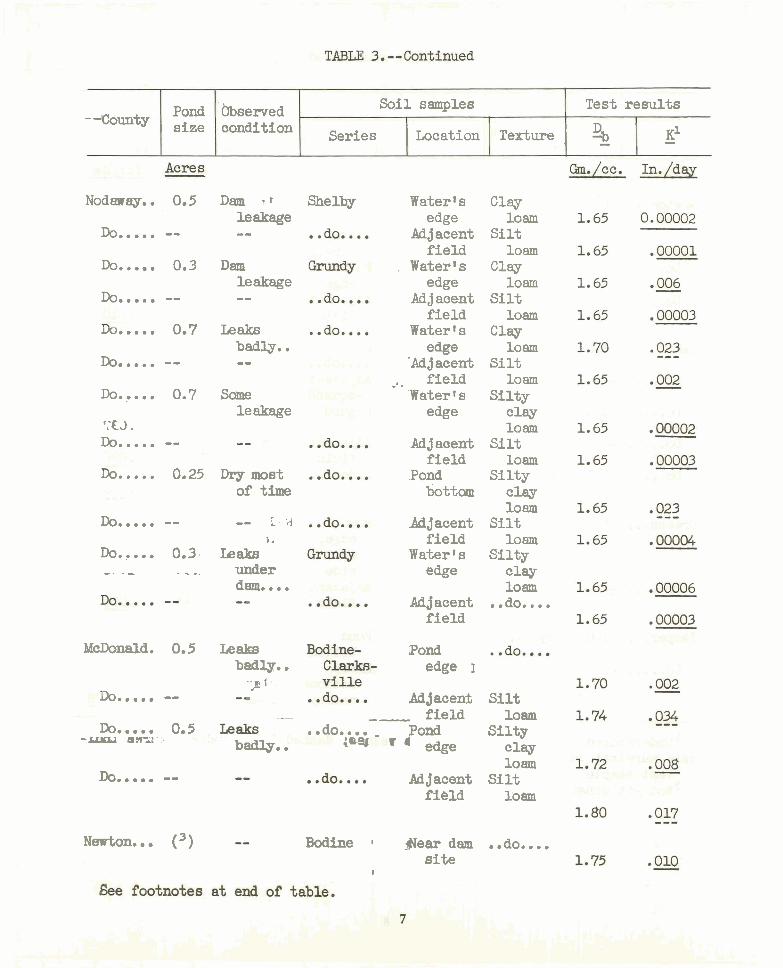
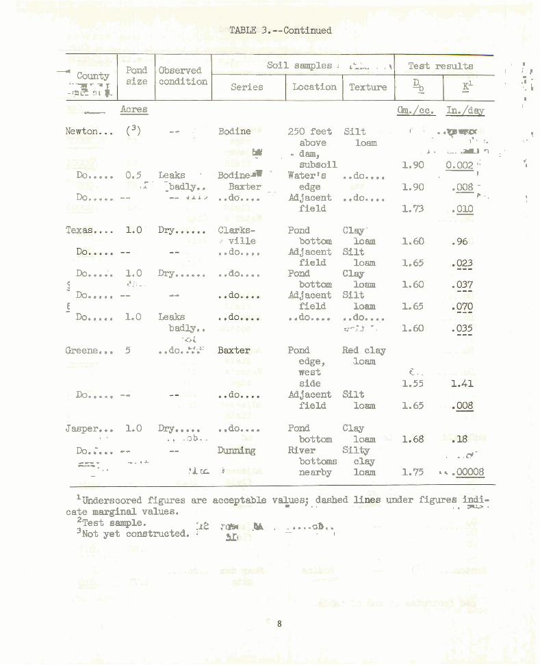
: '- The description of the tests of the soil samples taken from pond sites are shown in table 3. I general, the hydraulic conductivity data for the silx a d sandy loams indicate these soils will
'seal satisfactorily if compacted to maximum density at optimum moistyre conditions. The soils of the Deep Loess Hills and the Central Mississippi Valley Wooded Slopes will uellnllv eeal better thUt the silt 10am smlace mils of the b a r k Higfilancfs. A certain degree of E less seems to persist in the silt loam soil samples after compaction.
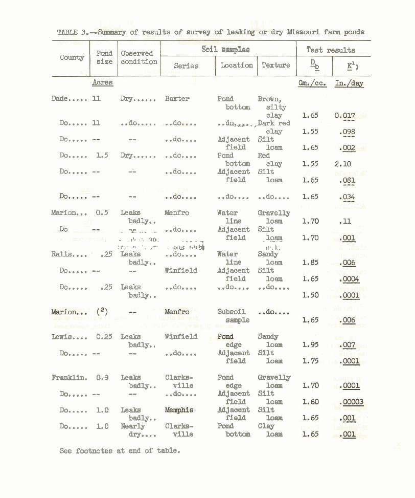
TABLE 3,--3ummary 02 resul ts of survey of leaJsing or dry Missouri farm ponds
Pond Observed Sbfl Sramples Test results County size condition
Series Location Texture 31 - - ~~3
Acres - Dade. .... 11 Dry.. .... Baxter
Do..... 11
Do..... . -- ..do.. .. .... ...... ..... Do 1.5 Dry ..do
Do..... -- -- .. do....
Marion... 0.5 Leaks Menfro badly..
no . -" - .... .do.. .. - ' . . ,\d 1 , - - -- -
, . . . . .?- . , 5t,a Rails.... .25 Leaks ..do. ...
badly.. Do..... -- - - Winfield
Do..... .25 Ieaks .. do.... badly..
ewi s . . . . 0.25 Leaks Winfield badly.,
Do..... -- -- . .do.. .. Franklin. 0.9 Leaks Clarks-
badly.. v i l l e Do..... -- -- .. do....
Do..... 1.0 Leaks badly..
Do..... 1.0 Nearly C l a r k s - dry.... vi l le
Pond bottom
. . d ~ s u * .
Adjacent f i e ld
Pond bottom
Adjacent f i e ld
B-, s i l t y clay
,Dark red clay
S i l t loam
Red c l w
S i l t loam
.. do.... .. do....
Water Gravelly line loam
Adjacent S i l t f i e ld - loam --
t i 1 . k 1 Water
line sazady
loern Adjacent S i l t
f i e ld loam ..do.. .do.. . . . . ..
Subsoil sample
cage Adjacent
field
Pond ease
Ad j acent field
Adjacent f i e ld
Pond bottosn
Sandy loam
S i l t loam
Gravelly loam
S i l t loam
S i l t loam
Clw loam
See footnotes a t end of table.
Pond bbserved Soil samples Test resul ts -Ccunty size condition Series Location Texture % - - KI
Nodaway.. 0.5
Do..... -- Do..... 0.3
Do..... -- me.... 0.7
Do..... -- Do..... 0.7
':E3 . Do..... -- uo..... 0.25
Do..... -- Do.,... 0.3. -- . - ~ - -.
McDonald. 0.5
Do..... -- Do..... 0.5 -- an-,I. :.
Do..... --
Newton... (3)
Dam r leakage - -
Dam leakage - -
Leaks badly.. --
same leakage
Dry most of time
-- r.;1 1
Leak8 under dam.. . . -
Leak8 badly.. .;E 1 . -
Shelby
I
..do.. . ,'tlri.. .tA Sharps-
burg i
.-
badly. . - . . do.. . . -,
iW
Water s edge
Adjacent f i e ld
. WaterIs edge
Ad j acent f ie ld
Water s cage
'Ad j acent , f ie ld
Water's cage
:Adjacent f ie ld
.Pond bottom
Adjacent f i e ld
Water ' s edge
Adjacent f ie ld
Pond edge 3
Ad j acenii - f i e ld Pond ' ' edge
Adjacent f ie ld
Clay loam
S i l t loam
Clay loam
S i l t loam
Clay loam
S i l t loam
S i l t y clay loam
S i l t loam
S i l ty clay loam
S i l t loam
S i l ty clay loam
.*do.. ..
S i l t loam
S i l t y cw loam
S i l t loam
Bodine I geardam ..do**.* s i t e
I
---4 Pond Observed Soil samples . , Test results I r l
County size condition . Series
- '-a- 7
-I.? s l j. Location Texture % - KI . '-I i - -- I
I - Acres Gm./cc. In./day L
- - Bodi 250 feet S i l t c ..~lrzry 1.
above loam 1 r. '. . w - dam, A . ,,,-I :
subsoil 1.90 0.002'' f I
Leaks ~ o d i n e a . Water's . .do.. .. I -
_badly.. Baxter - . e@e 1.90 .008 - - -- .. do.... Adjamnt .. ao.... F . , 7
Do..... 0.5 - - I I
Do..... -- f ie ld 1.73 .010 -
Text C l a r k s - .! vi l le ..do.*. .
Pond bottom
Adjacent f ie ld
Pond bottom
Adjacent f ie ld . .do. ...
Clay ' loam 1.60
S i l t loam 1.65
C l a g loam 1.60
S i l t loam 1.65 .. do. ....
Y~---~.T * 1.60
Do...;. 1.0 Dry ...... 5 2 ; : - : - Do..... -- - -
.. do....
E - Do..... 1.0 Leaks
badly.. 'GL
Greene.. . 5 . . do. .Y ic: Pond Red clay edge, .loam west cl. side 1.55
Adjacent S i l t f ie ld loarm 1.65
Do...... --
..... . .. Jasper... 1.0 Dry .do.. Pond b - Clay
+ , sb.. bottom loam Do.;... -- - - River Sil ty
r . @ * - -- - -. * A -. bottoms clay 1 I - C i r ~ i nearby loam 1.75 ~+.00008
'Underscored figures are acceptable veluesj , . dashed li cate marginal values.
* ~ e s t sample. :ti? tm .aa . - . +. .&. . 3 ~ o t yet constructed. ;
- x4 - I
1 under figures indi- , . m%-.
. L . .
, 8 , ,,t - I I -. I
. m
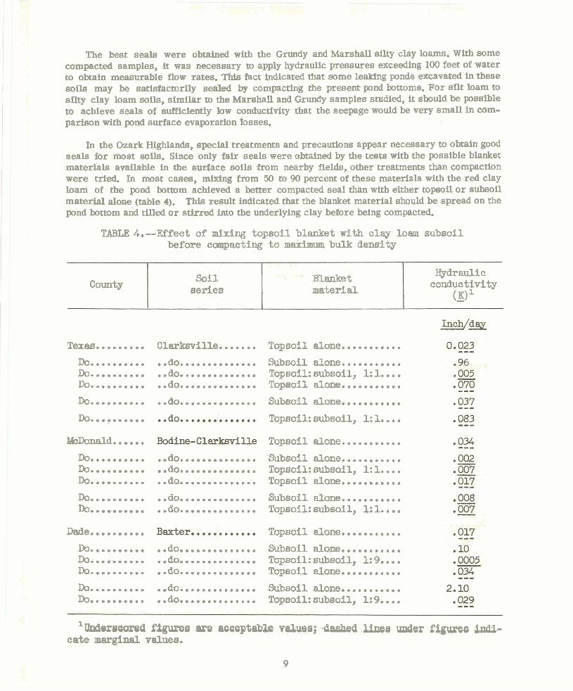
The best seals were obtained with the Grundy and Marshall silty clay loams. With some compacted samples, it was necessary to apply hydraulic pressures exceeding 100 feet of water to obtain measurable flow rates. This fact indicated that some leaking ponds excavated in these soils may be satisfactorily sealed by compacting the present pond bottoms. For sflt loam to silty clay loam soils, similar to the Mar~hal l and Grundy samples studied, it should be possible to achieve seals of sufficiently low conductivity that the seepage would be very small in com- parison with pond surface evaporation losses.
In the Ozark Highlands, special treatments and precautions appear necessary to obtain good seals for most soils. Since only fair seals were obtained by the tests with the possible blanket materials available in the surface soils from nearby fields, other treatments than compaction were Wed. In most cases, mixing from 50 to 90 percent of these materials with the red clay loam of the pond bottom achieved a better compacted seal than with either topsoil o r subsoil material alone (table 4). This result indicated that the blanket material should be spread on the pond bottom and tilled o r stirred into the underlying clay before being compacted.
TABLE 4.--Effect of mixing topsoil blanket with clay loam subsoil before compacting t o maximum bulk density
Texas......... Clarksville. ......
Hydraulic conductivity
(_K> County
.......... Topsoil alone. -.
Soil Blanket series material
Do.......... Do.......... Do..........
.. do...........,.. .. do.............. .. do..............
Subsoil alone.........., .. Topsoil: subsoil, 1: 1.. Top~oi l alone...........
Do.......... .. do.............. Subsoil alone...........
Do.......... .. Topsoil: subsoil, 1: 1..
McDonald.. e... Topsoil alone...........
Do.......... Do.......... m..........
.. do.............. .. do.............. .. do..............
'Subsoil alone........... Topsoil: subsoil, 1: 1.. .. Topsoil alone.....,.....
Do.......... Do ........... .. do.............. . .do.. ... 0 0 , . ...... Subsoil alone...........
Topsoil: subsoil, 1: 1.. .. Topsoil alone........... Dade..........
Do.......... Do.......... Do..........
.. do.............. .. do.............. .. do..............
Subsoil alone........... Topsoil: subsoil, 1: 9.. .. Topsoil alone...........
Do.......... Do..........
.. do.............. .. do.............. Subsoil alone........... Topsoil: subsoil, 1: 9.. ..
1 UndwscoreQ figuxes am aoaeptsib&- va;lu@i~; -dashed U a under figures tsdli- cate marginal values.
9
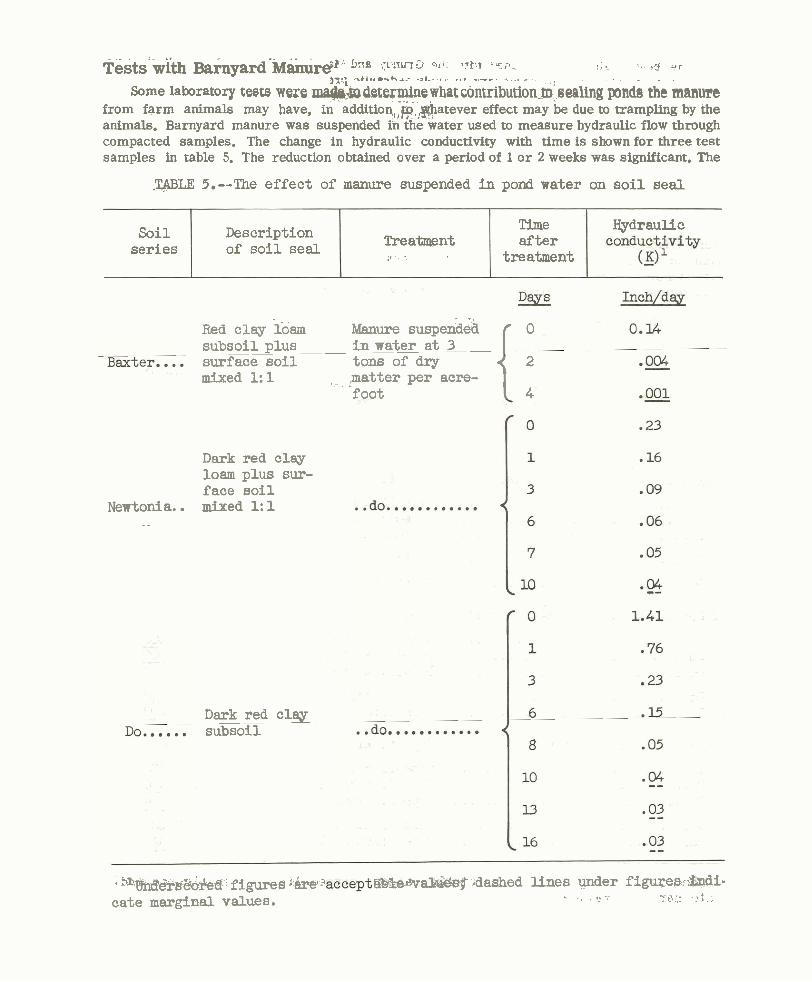
T&sti-With B & y a a r d * ~ ~ $ ~ ' h"B C K .IU-r" 9.1. i q t ' ~ fibtp. 8 L ' 3 13 a r ,=.; x b i . . . ~ + . A . - - 3 , - . - ... - -- . - Some laboratory tests were derermine what cdntribudon-m! sealing i n d s che manun
from farm animals may have, in addition,&.:@atever effect may be due to trampling by the animals. Barnyard manure was suspended in the water used to measure hydraulic flow through compacted samples. The change in hydraulic conductivity with time is shown for three test samples in table 5. The reduction obtained over a period of 1 o r 2 weeks was significant. The
-T$BLE 5.--The effect of manure suspended i n pond water on s o i l seal
Newtonia. . -
Red clay loam mure suspend& 0 subsoil plus i n water at 3 ------------
surface so i l tons of dry 2 mixed 1: 1 1 , I matter per acre-
foot 4
Time after
treatment
Dark red c l a y loam plus sur- f a c e soil mixed 1: 1
Trea-nt ,I
Soil series
Dark red clay -----
subsoil
Description o f so i l seal
Hydraulic
i m ~ E ~ ~ figures '.kt W2e*al&3eg dashed lines under f iguyes. ~ a d i - cate marginal values. - .*.,-. - 7 . .t': . * t . ,
hydraulic conductivity was reduced to an acceptable level by the treatment when the initial value was less than 0.2 inch per day. Further tests with ammonia in solution indicated that this con- stituent of the manure was not responsible. The sealing effect is probably due to some complex organic material. However, tests with organic gums and acrylic poaymers gave disappointing results. suspended clay o r ground hay in the water improved sealing but to a somewhat lesser degree than manure.
Tests with Polyphosphates and Silicates 6
1 Since soil puddling o r a soil-dispersing action may be largely responsible for the effect
i obtained by the trampling of animals in reducing pond seepage, laboratory tests were made with chemical dispersants. The dispersants studied were sodium hexametaphosphate and sodium tripolyphosphates (condensed phosphates) as well as sodium silicate (water glass). Results with a soil from a Dade County pond a r e shown in table 6. The effects of the sodium hexametaphosphate a r e often spectacular. Changes in conductivity with additions of sodium tripolyphosphate were not so noticeable and even less so with water glass. Other tests using soda lime and ammonia gave small decreases in conductivity.
It is evident that the dispersing effect of the condensed phosphates of sodium is largely due to the formation of soluble ion complexes with the multivalent cations in the soil (such a s iron, aluminum, calcium, and magnesium), which a re responsible for binding clay particles in stable floccules o r aggregates. The activity of the flocculating polyvalent cations is reduced and replaced by the monovalent cation sodium. Also, the condensed phosphate is strongly adsorbed on the clay particles. The process virtually rips the clay mineral apart, owing to the complexing of iron and aluminum.' At the same bulk density, a puddled mass of dispersed clay will be less per- meable than a gravel-like body of aggregates before dispersion. Unfortunately, the condensed phosphates hydrolyze to ordinary orthophosphate, so that precipitation and a reversion to the aggregation of the clay particles may be expected after several months' time.
Although chemical treatments a r e quite effective, they may in some cases be too expensive to, be practical. The use of mechanical dispersion methods, either by machinery that may be designed to tread o r s t i r the soil below the pond water surface o r simply by allowing animals to trample in the pond, may be more satisfactory--at least, from the cost standpoint.
Tests with Emulsions Some asphalt-water emulsions and a commercial pond sealing emulsion were tested. The
results with asphalt emulsions, either mixed in the soil o r suspended in the water, were d i s a p pointing. The decreases obtained differed little from those that were obtained by working and compacting the soil to the same extent in a slightly wet condition. Tests with the commercial emulsion indicated that i t will reduce the flow rate about 60 o r 70 percent. These results were consistent with the claims of the distributors of this mterial . However, for sealing farm ponds, a more effective method o r material is needed.
LABORATORY MODEL STUDIES
It would be extremely difficult &I determine the distribution bf hydraulic pressures and flow characteristics in the soil under a hnd. Yet these relarionships, especially in the top of the soil
, 4 ~ ~ 3 0 n a 1 cammiation from R R b r a s , si,n scfentist, oil and Water ~oas~lratim~&searchlllvisim.
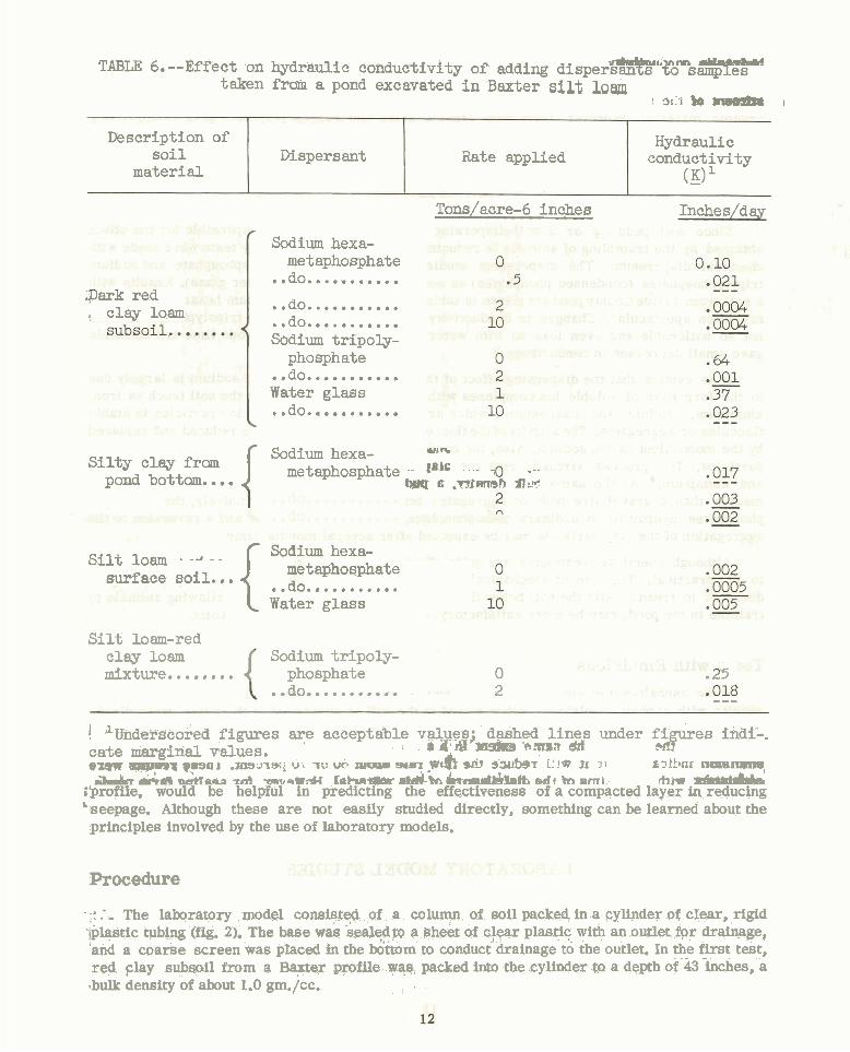
TABLE 6. --Effect on hydraulic conductivity of adding d i ~ ~ e r ~ ' ' % ~ s ~ taken frah a pond excavated i n Baxter silt lorn
1 31'1 bO I -
Tons/acre-6 inches Inches/d ay
Description of s o i l
material
;park red ! clay loam
r
Sodium hexa- met aphosphat e .. do...........
.. do........... .. do........... Sodium tripoly-
phosphate .. do........... Water glass .. do...........
b
Dispersant
I Sodium hexa- WJIF S i l t y clay from metaphosphate - fakc - - .- pond bottom.... wq e .mmh a,* - - sdl ,yls *do* k ~ 4 tdnga~a lo VLIT . & + , m a r . .. do... ........ y m l b
Rate applied
S i l t loam - -" - - surface so i l . met aphosphate .. I hexa-
Hydraulic conductivity (x>l
1 .. UU...........
[ Water glass
S i l t loam-red clay loam Sodium tripoly- mixture........ phosphate 0 . ~5 .. do.........*. 2 ---
! l ~ d e r s c o r e d figures a? acceptable values; dashed l ines under figures indiL. . rcW 'msbbrs'e-ma &I NT? cate nrarglrial aalues.
. - - F v F a l .nnnqufi wuc~nw-~hui ,-r ;:la a 71 ~2kbnr num- aka wtflam~ tni -sw;sCI hhn* d h kand&bk edr in eni & k r -'
;profile, would be helpful in predicting the effectiveness of a compacted layer in reducing 'seepage. Although these a re not easily studied directly, something can be learned about the principles involved by the use of laboratory models.
Procedure
- ;: I, The laboratory model consiflfep of. a column- of soil packed in a cylinder of clear, rigid .~pl+stic tubing (fig. 2). The base was kealedto a ~ h e e t of ct+r plastic with an outlet for dra-ple, land a coarse screen was placed in the &&om to conduct drainage to the outlet. In the first test, red @ay subsoil from a Ba.@er p f i l e we, packed into the cylinder a depth of 43-khes, a .bulk density of about 1.0 gm./cc. I .
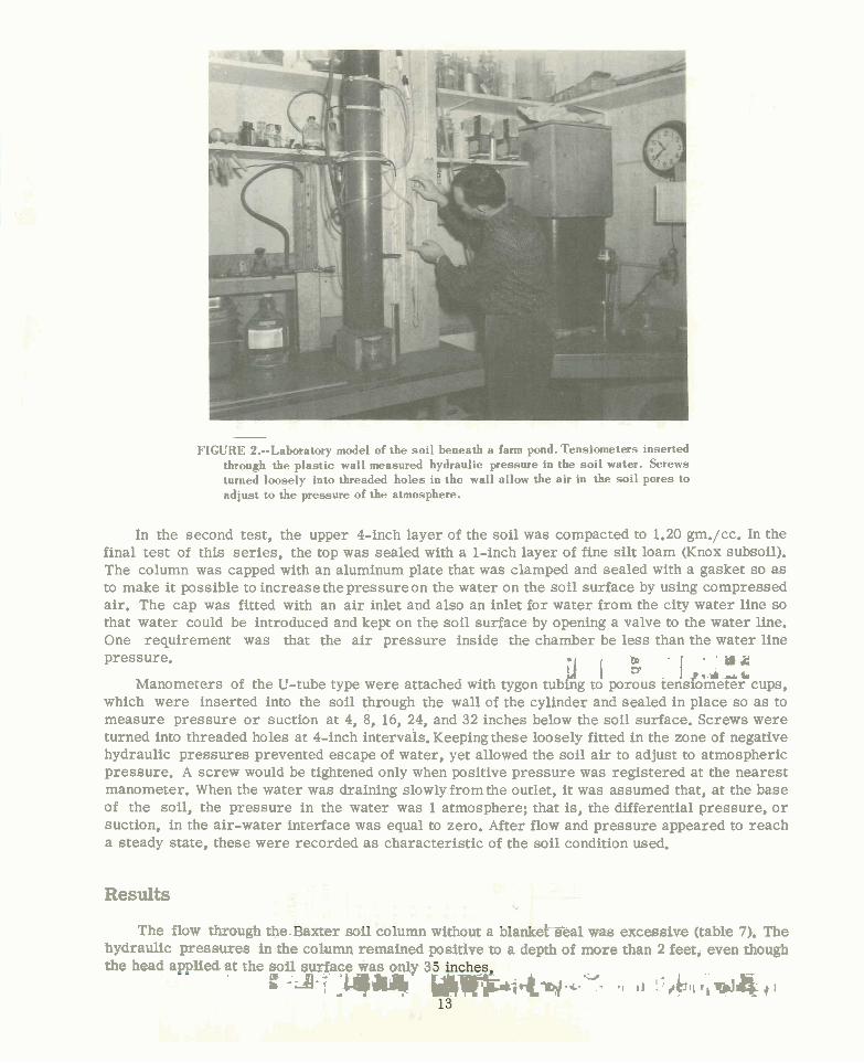
- FIGURE 2.--Laboratory model of the soi l beneath a farm pond. Tensiometers inserted
through the plastic wall measured hydraulic pressure in the soi l water. Screws turned loosely into threaded holes in the wall allow the air in the soi l pores to adjust to the pressure of the atmosphere.
In the second test, the upper 4-inch layer of the soil was compacted to 1.20 grn./cc. In the final test of this series, the top was sealed with a 1-inch layer of fine silt loam (Knox subsoil). The column was capped with an aluminum plate that was clamped and sealed with a gasket so a s to make it possible to increase the pressureon the water on the soil surface by using compressed air. The cap was fitted with an a i r inlet and also an inlet for water from the city water line so that water could be introduced and kept on the soil surface by opening a valve to the water line. One requirement was that the a i r pressure inside the chamber be less than the water line pressure. zn ' m & i / I .id&
Manometers of the U-tube type were attached with tygon tubing to porous tensiometer cups, which were inserted into the soil through the wall of the cylinder and sealed in place so a s to measure pressure o r suction at 4, 8, 16, 24, and 32 inches below the soil surface. Screws were turned into threaded holes at 4-inch intervals. Keeping these loosely fitted in the zone of negative hydraulic pressures prevented escape of water, yet allowed the soil a i r to adjust to atmospheric pressure. A screw would be tightened only when positive pressure was registered a t the nearest manometer. When the water was draining slowlyfrom the outlet, it was assumed that, at the base of the soil, the pressure in the water was 1 atmosphere; that is, the differential pressure, o r suction, in the air-water interface was equal to zero. After flow and pressure appeared to reach a steady state, these were recorded a s characteristic of the soil condition used.
Results
The flow through the-baxter mil column wiithout a ~ranuetTea1 was excessive (table 7). The hydraulic pressures in the column remained positive to a depth of more than 2 feet, even though -
the head appliect at the soil surface was only 3 ' f - J a y - .yJw, l4w.L. W - ~:&l,*,aq,l
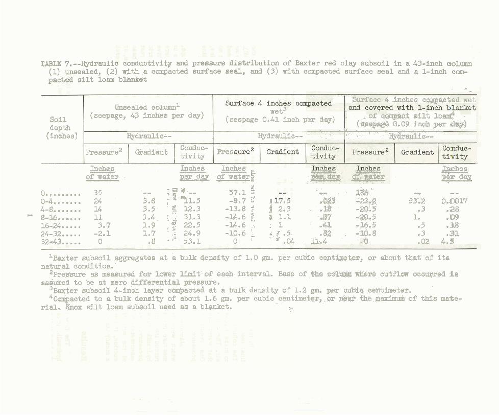
TABLE 7,--Hydraulic conductivi$y and prqssure distribution of Baxter red clay subsoil i n a 43-inch aolumn (1) w e a l e d , (2) with a campacted surf ace seal, and (3) with compacted surface seal and a l-inch com- acted si l t loam blanket
Soil depth
(inches)
. a - .. . -- -, --
'rcurf ace 4 incrhes oompacled wet IJnsealed column1 wet3
(seepage, 43 2n-s per day) (seepage 0.41 inch par diw) - &%s c q c & erl1.t 104 - (&elsag@ 0.09 inch per drgr)
? - . - ., . ,
Hydraulic-- Hydraulic-- , .., .-. - . I. . . : ..7r ' WKTQ&C-- -
Conduo- e e s Pressure2 Gradient tivity w
Inches - Inches Inches - - +bches of wa;tsr per d w -of waterf pE,r day
3
;a*" 57.1 3 0.. ....... 35 -- mi- ' 8 , Zg& ' -* -- 3.8 ; a 91.5 -8.7 C' a 17.5 +%023 0-4.5..... 24 c23..0.;2 53i2 Q.A9017
4-8,....... U 3.5 !! 12.3 -U.8 f 4 2.3 . .2& -2Q.Y .3 .28 B- 8-3.6...... 11 1.4 ' 31.3 - U . 6 $ , 4 1.1 - 4 7 -20.5 1. .09
1 6 2 4 - 3.7 1.9 'la t s 22.5 -l4.6 -, : 1 ImRJ -16.5 05 0 1 8 24-32..... -2.1 1.7 '.i 24.9 -10.6 1 k j . 5 O M . -10.8 .3 ,3& 3243..... 0 r 8 ' - 53.1 0 ' .04 . lk.4 .O2 4.5
-
L ~ w t e r subsoil aggregates a t a bulk density of 1.0 gm. per cudiic cent@@ter, or abouti mat' of its natural. condition. '
2 ~ ~ e a s u r e as measwed for lower limit of each interval. Base of ,$b@ c G Z ~ %here ou%fluw accusred f a askiufned t o be a t zero differential presswe.
'~ax-ber subsoil 4-in& l w e r compacted a t a bulk density of 1.2 gm. per cub13 centimeter. 4 ~ a c t e d t o a bulk density of sbout 1.6 grp. per cubic centimetm, .or. gear ..the maximum of W.B mate-
rial, Mnox silt- loam subsoil used as a blanket. -
h . \ -
The wet compaction treatment had a pronounced effect on the hydraulic pressure distribution in the column as well a s the flow velocity. With a hydraulic head of nearly 6 feet of water at the surface, the pressure dropped to a suction of about 9 inches of water at the 4-inch depth. The soil remained unsaturated (under suction) throughout the remainder of the-plumn. Thers-eepage rate was reduced to about 1 percent of that of the unsealed column. j
' . ' e iTF
, The compacted 1-inch silt loam seal further reduced seepage and increased the pressure
gradient iq the surface layer. Even with more than 15.5 feet of head at the surface, the pressure dropped to negative (suction) values at the 4-inch depth. The hydraulic conductivity of the surface layer was decreased from 11.5 inches to 0.0017 inch per day by the combined wet and blanket treatments.
The results of this model study indicate that, even under leaking ponds, the soil water may be at pressures below that of the atmosphere at a foot o r two below the soil surface under the pond. When there is a good seal of the soil surface beneath the pond, the soil water is probably under suction just a few inches beneath the seal, even at hydraulic heads of more than 10 feet of water. The suction effect will make a small contribution to the hydraulic gradient and, hence, the forces causing seepage. With a good seal, this effect will be negligible.
The observed drop from the applied pressure to suction over the sealed interval has one further practical application. If sufficient supporting strength is providkd beneath the seal, a coarse aggregate o r gravelly zone below the sealed layer will contribute less to seepage than a moderately fine material, since water will not enter large pores until the suction force is very low o r the pressure becomes positive. Water moving under suction force of about 0.1 atmosphere o r greater will flow faster at the same gradient through dispersed medium-to-fine-textured soil particles than through sand, gravel, o r loose aggregates.
FIE W)
Procedure
TESTS
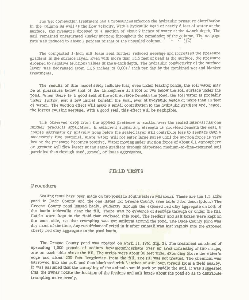
Sealing tests have been made on two pond,^ m southwestern ndissouri. These are the 1.5-acre pond in Dade County and the one listed for Greene County. (See table 3 for description.) The Greene County pond leaked badly, evidently through the exposed red clay aggregate on both of the basin sidewalls near the fill. There was no evidence of seepage through o r under the fill. Cattle were kept in the field that enclosed thls pond. The feeders and salt boxes were kept on the east side, so that trampling was not uniform around the pond. The Dade County pond was dry most of thetime. Any runoff that collected in it after rainfall was lost rapidly into the exposed cherty red clay aggregate in the pond basin.
The Greene County pond was treated on April 11, 1961 (fig. 3). The treatment consisted of spreading 1,000 pounds of sodium hexametaphosphate over an area consisting of two strips, one on each side above the fill. The strips were about 30 feet wide, extending above the water's edge and about 200 feet lengthwise from the fill. The fill was not treated. The chemical was harrowed into the soil and then blanketed with 3 inches of silt loam topsoil from a field nearby. It was assumed that the trampling of the animals would pack o r puddle the soil. It was suggested that the owner rotate the location of the feeders and salt boxes a h t the pond so as to distribute trampling more evenly.
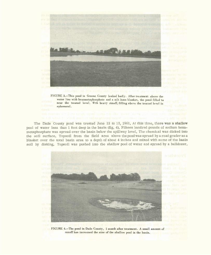
FIGURE 3.--This pond in Greene County leaked badly. After treatment above tne water line with hexametaphosphate and a silt loam blanket, the pond filled to near the treated level. With heavy runoff, filling above the treated level i s ephemeral.
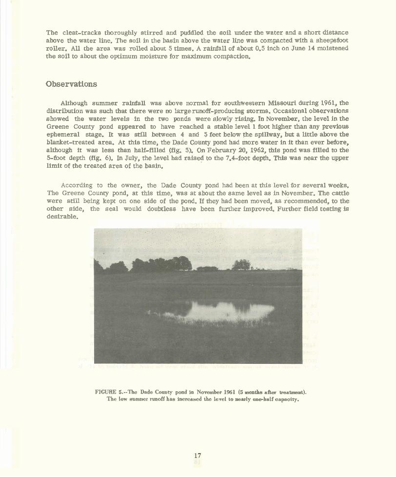
The uaae County pond was treated June 12 to 15. 1961. At t b nme. me - - pool of water less than 1 foot deep in the basin (fig. 4).- ift teen hundred pobnds of sodium hexa- metaphosphate was spread over the basin below the spillway level. The chemical was disked into the soil surface. Topsoil from the field area above the pond was spread by a road grader a s a blanket over the total basin area to a depth of about 4 inches and mixed with some of the basin soil by disking. Topsoil was pushed into the shallow pool of water and spread by a bulldozer.
The cleat-tracks thoroughly stirred and puddled the soil under the water and a short distance above the water line. The soil in the basin above the water line was compacted with a sheepsfoot roller. Al l the area was rolled about 5 times. A rainfall of about 0.5 inch on June 14 moistened the soil to about the optimum moisture for maximum compaction.
Observations
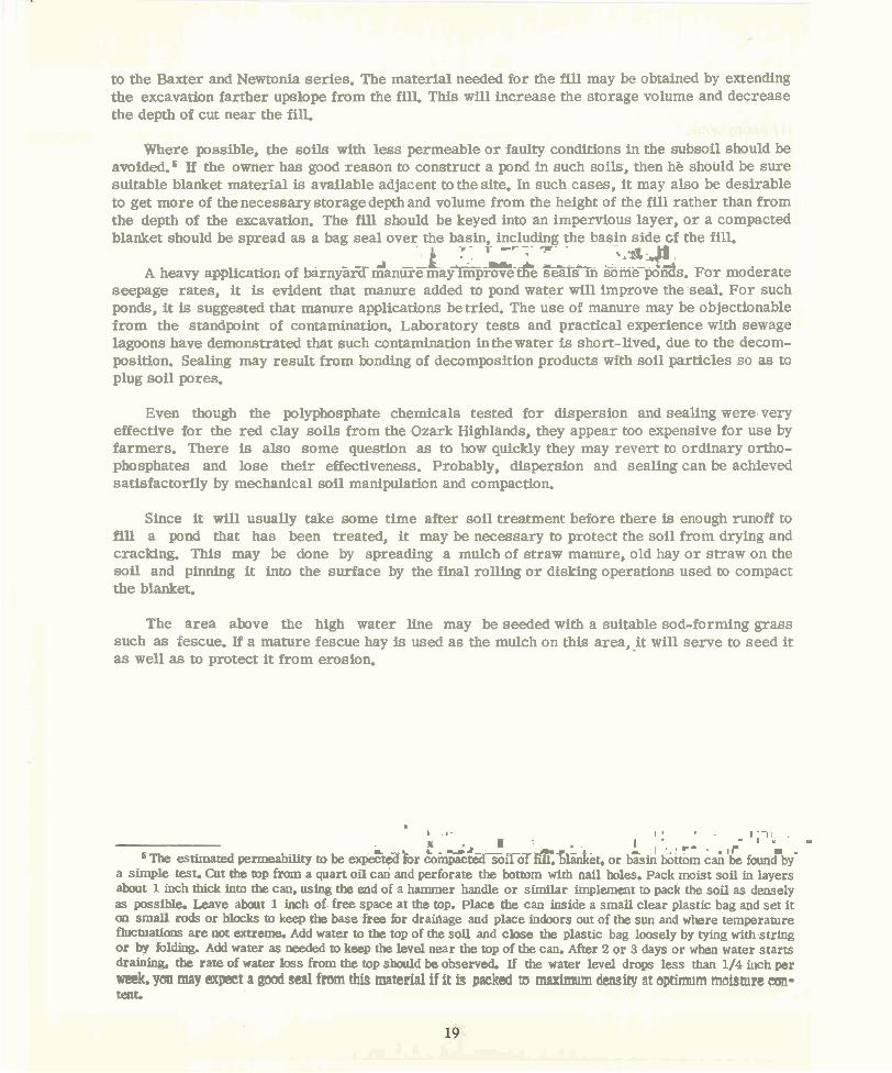
Although summer rainfall was above normal for southwestern Missouri during 1961, the distribution was such that there were no large runoff-producing storms. Occasional observations showed the water levels in the two ponds were slowly rising. In November, the level in the Greene County pond appeared to have reached a stable level 1 foot higher than any previous ephemeral stage. It was still between 4 and 5 feet below the spillway, but a little above the blanket-treated area. At this time, the Dade County pond had more water in it than ever before, although it was less than half-filled (fig. 5). On February 20, 1962, this pond was filled to the 5-foot depth (fig. 6). In July, the level had raised to the 7.4-foot depth. This was near the upper limit of the treated area of the basin.
According to the owner, the Dade County pond had been at this level for several weeks. The Greene County pond, a t this time, was at about the same level as in November. The cattle were still being kept on one side of the pond. If they had been moved, a s recommended, to the other side, the seal would doubtless have been further improved. Further field testing is desirable.
FIGURE 5.--The Dade County pond in November 1961 (5 months after treatment). The low summer runoff has increased the level to nearly -half capacity.
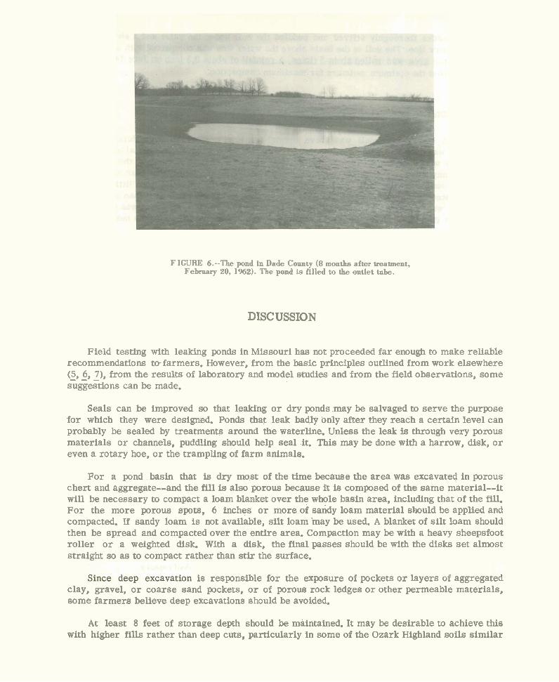
FIGURE 6.--The pond in Dade County (8 months after treatment, February 20, 1962). The pond is filled to the outlet tnbe.
DISCUSSION
Field testing with leaking ponds in Missouri has not proceeded far enough to make reliable recommendations tefarmers. However, from the basic principles outlined from work elsewhere (5, - - - 6, 7), from the results of laboratory and model studies and from the field observations, some suggestions can be made.
Seals can be improved so that leaking o r dry ponds may be salvaged to serve the purpose for which they were designed. Ponds that leak badly only after they reach a certain level can probably be sealed by treatments around the waterline. Unless the leak is through very porous materials o r channels, puddling should help seal it. This may be done with a harrow, disk, o r even a rotary hoe, o r the trampling of farm animals.
For a pond basin that is dry most of the time because the area was excavated in porous chert and aggregate--and the fill is a h porous because i t is composed of the same material--it will be necessary to compact a loam blanket over the whole basin area, including that of the fill. For the more porous spots, 6 inches o r more of sandy loam material should be applied and compacted. If sandy loam is not available, silt loam .may be used. A blanket of si l t loam should then be spread and compacted over the entire area. Compaction may be with a heavy sheepsfoot roller o r a weighted disk. With a disk, the final passes should be with the disks set almost straight so as to compact rather than stir the surface.
is responsible for the exposure of pockets o r layers of aggregatea clay, gravel, o r coarse sand pockets, o r of porous rock ledges o r other permeable materials, some farmers believe deep excavations should be avoided.
At least 8 feet of storage depth should be maintained. It may be desirable to achieve this with higher fills rather than deep cuts, particularly in some of the Ozark Highland soils similar
to the Baxter and Newtonia series. The material needed for the fill may be obtained by extending the excavation farther upslope from the fill. This will increase the storage volume and decrease the depth of cut near the fill.
Where possible, the soils with less permeable o r faulty conditions in the subsoil should be avoided. If the owner has good reason to construct a pond in such soils, then he should be sure suitable blanket material is available adjacent to the site. In such cases, it may also be desirable to get more of the necessary storage depth and volume from the height of the fill rather than from the depth of the excavation. The fill should be keyed into an impervious layer, o r a compacted blanket should be spread as a bag -. seal - - over the basin, including the basin side of the fill. -, - r--r -- 7- -
' I L a - ,-. *.a -p 1
-
A heavy application of birnY'ar7 dantiTtFmay~Prove &e 8eaTfin &me-poi&. For moderate seepage rates, i t is evident that manure added to pond water will improve the seal. For such ponds, i t is suggested that manure applications betried. The use of manure may be objectionable from the standpoint of contamination. Laboratory tests and practical experience with sewage lagoons have demonstrated that such contamination inthewarer is short-lived, due to the decom- position. Sealing may result from bonding of decomposition products with soil particles so as to plug soil pores.
Even though the polyphosphate chemicals tested for dispersion and sealing were very effective for the red clay soils from the Ozark Highlands, they appear too expensive for use by farmers. There is also some question a s to how quickly they may revert to ordinary ortho- phosphates and lose their effectiveness. Probably, dispersion and sealing can be achieved satisfactorily by mechanical soil manipulation and compaction.
Since it will usually take some time after soil treatment before there is enough runoff to fill a pond that has been treated, i t may be necessary to protect the soil from drying and cracking. This may be done by spreading a mulch of straw manure, old hay o r straw on the soil and pinning it into the surface by the final rolling o r disking operations used to compact the blanket.
The area above the high water line may be seeded with a suitable sod-forming grass such as fescue. If a mature fescue hay is used a s the mulch on this a reas i t will serve to seed it a s well a s to protect it from erosion.
b L r -
I : . . 1 , 1 1 . r I ' - . ' , , . o w - a .,r -
5 The estimated permeability to be expkdhx & i n ~ * ~ o i l % ~ ~ , $ k & e t , or b%in knnn can h found'bi a simple test. Cut the top from a quart oil can and perforate the bottom with nail holes. Pack moist soil in layers about 1 inch thick into the can. using the end of a hammer handle or similar implement to pack the soil as densely as possible. Leave about 1 inch of free space at the top. Place the can inside a small clear plastic bag and set it on small rods or blocks to keep the base free for drainage and place indoors out of the sun and where temperature fluctuations are not extreme. Add water to the top of the soil and close the plastic bag loosely by tying with string or by folding. Add water as needed to keep the level near the top of the can. After 2 or 3 days or when water starts drainhg, the rate of water loss from the top should be observed. If the water level drops less than 1/4 inch per we&, you may cxpeet a goal seal fmm this material if it is packed to m a x i m density at sptimum moisture can- teat.
LITERATURE CITED E T
k r ? mm (1) Anonymous. 4 v
1960. Sealing earth dams. Australia Commonwealth Sci. and Indus. Res. Organ. Rural Res. 32: 10-11.
(2) 1960. Study seepage from western Iowa reservoirs. Iowa Farm Sci. 15(10): 14-690.
(3) Dirmeyer, R. D., Jr. 1962. Progress report of clay sealing investigations during 1961. Colo. State Univ. Civil
Engin. Sect. Rpt. 62RDD8: 1-8.
(4) and Shen, R. T. 1960. Sediment sealing of irrigation canals. Colo. State Univ. Civil Engin. Sect. Rpt.
60RDD33: 1-124.
(5) Holtan, H. N. 1950. Holding water in farm ponds. U.S. Dept. Agr. SCS-TP-93.
(6) 1950. Sealing farm ponds. Agr. Engin. 31: 125130, 133-134.
(7) Kroth, E. M., Jamison, V. C., and Grogger, H. E. 1960. Soil moisture survey of sonie representative Missouri soil types. U.S. Dept. Agr.
ARS-41-34: 3-41.
(8) North Central Region Technical Committee on Soil Survey. 1960. Soils of the north central region of the United States. North Cent. Region Pub.
76: 70-118; Wis. Univ. Bul. 544.