Embed Size (px)
Citation preview
BRITISH STANDARD BS EN 10216-2:2002
Seamless steel tubes for pressure purposes — Technical delivery conditions —
Part 2: Non-alloy and alloy steel tubes with specified elevated temperature properties
The European Standard EN 10216-2:2002 has the status of a British Standard
ICS 23.040.10; 77.140.75
NO COPYING WITHOUT BSI PERMISSION EXCEPT AS PERMITTED BY COPYRIGHT LAW
Copyright European Committee for Standardization Provided by IHS under license with CEN
Document provided by IHS Licensee=Borealis/9990751100, 10/28/2004 13:58:36 MDTQuestions or comments about this message: please call the Document Policy Groupat 303-397-2295.
--`,```,`,,`,``,`,```,`,,`,,-`-`,,`,,`,`,,`---

BS EN 10216-2:2002
This British Standard, having been prepared under the direction of the Engineering Sector Policy and Strategy Committee, was published under the authority of the Standards Policy and Strategy Committee on 26 June 2002
© BSI 26 June 2002
ISBN 0 580 39838 2
National foreword
This British Standard is the official English language version of EN 10216-2:2002. Together with BS EN 10217-2:2002 it replaces BS 3059-2, BS 3602-1, BS 3604-1 and BS 3606:1992 which is withdrawn.
The UK participation in its preparation was entrusted by Technical Committee ISE/73, Steels for pressure purposes, to Subcommittee ISE/73/1, Steel tubes for pressure purposes, which has the responsibility to:
A list of organizations represented on this subcommittee can be obtained on request to its secretary.
Cross-referencesThe British Standards which implement international or European publications referred to in this document may be found in the BSI Catalogue under the section entitled “International Standards Correspondence Index”, or by using the “Search” facility of the BSI Electronic Catalogue or of British Standards Online.
This publication does not purport to include all the necessary provisions of a contract. Users of this publication are responsible for their correct application.
Compliance with a British Standard does not of itself confer immunity from legal obligations.
— aid enquirers to understand the text;
— present to the responsible international/European committee any enquiries on the interpretation, or proposals for change, and keep the UK interests informed;
— monitor related international and European developments and promulgate them in the UK.
Summary of pagesThis document comprises a front cover, an inside front cover, the EN title page,pages 2 to 40, an inside back cover and a back cover.
The BSI copyright date displayed in this document indicates when thedocument was last issued.
Amendments issued since publication
Amd. No. Date Comments
Copyright European Committee for Standardization Provided by IHS under license with CEN
Document provided by IHS Licensee=Borealis/9990751100, 10/28/2004 13:58:36 MDTQuestions or comments about this message: please call the Document Policy Groupat 303-397-2295.
--`,```,`,,`,``,`,```,`,,`,,-`-`,,`,,`,`,,`---

EUROPEAN STANDARD
NORME EUROPÉENNE
EUROPÄISCHE NORM
EN 10216-2
May 2002
ICS 23.040.10; 77.140.75
English version
Seamless steel tubes for pressure purposes - Technical deliveryconditions - Part 2: Non-alloy and alloy steel tubes with specified
elevated temperature properties
Tubes sans soudure en acier pour service sous pression -Conditions techniques de livraison - Partie 2: Tubes enacier non allié et allié avec caractéristiques spécifiées à
température élevée
Nahtlose Stahlrohre für Druckbeanspruchungen -Technische Lieferbedingungen - Teil 2: Rohre ausunlegierten und legierten Stählen mit festgelegten
Eigenschaften bei erhöhten Temperaturen
This European Standard was approved by CEN on 25 April 2002.
CEN members are bound to comply with the CEN/CENELEC Internal Regulations which stipulate the conditions for giving this EuropeanStandard the status of a national standard without any alteration. Up-to-date lists and bibliographical references concerning such nationalstandards may be obtained on application to the Management Centre or to any CEN member.
This European Standard exists in three official versions (English, French, German). A version in any other language made by translationunder the responsibility of a CEN member into its own language and notified to the Management Centre has the same status as the officialversions.
CEN members are the national standards bodies of Austria, Belgium, Czech Republic, Denmark, Finland, France, Germany, Greece,Iceland, Ireland, Italy, Luxembourg, Malta, Netherlands, Norway, Portugal, Spain, Sweden, Switzerland and United Kingdom.
EUROPEAN COMMITTEE FOR STANDARDIZATIONC OM ITÉ EUR OP ÉEN DE NOR M ALIS AT IONEUROPÄISCHES KOMITEE FÜR NORMUNG
Management Centre: rue de Stassart, 36 B-1050 Brussels
© 2002 CEN All rights of exploitation in any form and by any means reservedworldwide for CEN national Members.
Ref. No. EN 10216-2:2002 E
Copyright European Committee for Standardization Provided by IHS under license with CEN
Document provided by IHS Licensee=Borealis/9990751100, 10/28/2004 13:58:36 MDTQuestions or comments about this message: please call the Document Policy Groupat 303-397-2295.
--`,```,`,,`,``,`,```,`,,`,,-`-`,,`,,`,`,,`---

EN 10216-2:2002 (E)
2
Contents
Foreword ....................................................................................................................... .............................................. 3
1 SCOPE ............................................................................................................................................................ 4
2 NORMATIVE REFERENCES ......................................................................................................................... 4
3 TERMS AND DEFINITIONS ........................................................................................................................... 5
4 SYMBOLS....................................................................................................................... ................................ 5
5 CLASSIFICATION AND DESIGNATION ................................................................................................ ....... 65.1 Classification .............................................................................................................. ................................... 65.2 Designation ................................................................................................................. ................................... 6
6 INFORMATION TO BE SUPPLIED BY THE PURCHASER.......................................................................... 66.1 Mandatory information....................................................................................................... ........................... 66.2 Options ..................................................................................................................... ...................................... 76.3 Examples of an order ........................................................................................................ ............................ 7
7 MANUFACTURING PROCESS......................................................................................................... ............. 87.1 Steel making process........................................................................................................ ............................ 87.2 Deoxidation process ......................................................................................................... ............................ 87.3 Tube manufacture and delivery conditions .................................................................................... ............ 8
8 REQUIREMENTS............................................................................................................................................ 88.1 General ..................................................................................................................... ...................................... 88.2 Chemical composition ........................................................................................................ .......................... 98.3 Mechanical properties....................................................................................................... .......................... 138.4 Appearance and internal soundness ........................................................................................... ............. 188.5 Straightness................................................................................................................ ................................. 188.6 Preparation of ends......................................................................................................... ............................ 188.7 Dimensions, masses and tolerances ........................................................................................... ............. 19
9 INSPECTION................................................................................................................................................. 249.1 Types of inspection......................................................................................................... ............................ 249.2 Inspection documents ........................................................................................................ ........................ 249.3 Summary of inspection and testing ........................................................................................... ............... 24
10 SAMPLING..................................................................................................................... ............................... 2510.1 Frequency of tests......................................................................................................... .............................. 2510.2 Preparation of samples and test pieces..................................................................................... ............... 26
11 TEST METHODS .......................................................................................................................................... 2711.1 Chemical analysis .......................................................................................................... ............................. 2711.2 Tensile test ............................................................................................................... .................................... 2711.3 Flattening test ............................................................................................................ .................................. 2811.4 Ring tensile test.......................................................................................................... ................................. 2911.5 Drift expanding test....................................................................................................... .............................. 2911.6 Ring expanding test ........................................................................................................ ............................ 3011.7 Impact test................................................................................................................ .................................... 3011.8 Leak tightness test ........................................................................................................ .............................. 3111.9 Dimensional inspection ..................................................................................................... ......................... 3211.10 Visual examination ........................................................................................................ .............................. 3211.11 Non-destructive testing ................................................................................................... ........................... 3211.12 Material identification................................................................................................... ............................... 3211.13 Retests, sorting and reprocessing ......................................................................................... ................... 32
12 MARKING...................................................................................................................... ................................ 3312.1 Marking to be applied...................................................................................................... ............................ 3312.2 Additional marking ......................................................................................................... ............................. 33
13 PROTECTION............................................................................................................................................... 33
Annex A (Informative) Creep rupture strength values ........................................................................... ............. 34
Annex ZA (informative) ......................................................................................................... ................................... 39
Bibliography (Informative)..................................................................................................... .................................. 40
Copyright European Committee for Standardization Provided by IHS under license with CEN
Document provided by IHS Licensee=Borealis/9990751100, 10/28/2004 13:58:36 MDTQuestions or comments about this message: please call the Document Policy Groupat 303-397-2295.
--`,```,`,,`,``,`,```,`,,`,,-`-`,,`,,`,`,,`---

EN 10216-2:2002 (E)
3
Foreword
This document (EN 10216-2:2002) has been prepared by Technical Committee ECISS/TC 29, "Steel tubes andfittings for steel tubes", the secretariat of which is held by UNI.
This European Standard shall be given the status of a national standard, either by publication of an identical textor by endorsement, at the latest by November 2002, and conflicting national standards shall be withdrawn at thelatest by November 2002.
This document has been prepared under a mandate given to CEN by the European Commission and theEuropean Free Trade Association, and supports essential requirements of EU Directive(s).
For relationship with EU Directive(s), see informative annex ZA, which is an integral part of this document.
Other Parts of EN 10216 are:
Part 1: Non-alloy steel tubes with specified room temperature properties.
Part 3 : Alloy fine grain steel tubes
Part 4 : Non-alloy and alloy steel tubes with specified low temperature properties
Part 5 : Stainless steel tubes
Another European Standard series covering tubes for pressure purposes is:
EN 10217: Welded steel tubes for pressure purposes
According to the CEN/CENELEC Internal Regulations, the national standards organizations of the followingcountries are bound to implement this European Standard: Austria, Belgium, Czech Republic, Denmark, Finland,France, Germany, Greece, Iceland, Ireland, Italy, Luxembourg, Malta, Netherlands, Norway, Portugal, Spain,Sweden, Switzerland and the United Kingdom.
Copyright European Committee for Standardization Provided by IHS under license with CEN
Document provided by IHS Licensee=Borealis/9990751100, 10/28/2004 13:58:36 MDTQuestions or comments about this message: please call the Document Policy Groupat 303-397-2295.
--`,```,`,,`,``,`,```,`,,`,,-`-`,,`,,`,`,,`---

EN 10216-2:2002 (E)
4
1 SCOPE
This Part of EN 10216 specifies the technical delivery conditions in two test categories for seamless tubes ofcircular cross section, with specified elevated temperature properties, made of non-alloy and alloy steel.
NOTE This Part of EN 10216 may also be applied for tubes of non-circular cross section; necessary modification shouldbe agreed a the time of enquiry and order.
2 NORMATIVE REFERENCES
This European Standard incorporates by date or undated reference, provisions from other publications. Thesenormative references are cited at the appropriate places in the text and the publications are listed hereafter. Fordate references, subsequent amendments to or revisions of, any of these publications apply to this EuropeanStandard only when incorporated in it by amendment or revision. For undated references the latest edition of thepublication referred to applies (including amendments).
The requirements of this European Standard rule when they differ from those in the standards and documentsreferred to below:
EN 10002-1, Metallic materials - Tensile testing - Part 1: Method of test (at ambient temperature).
EN 10002-5, Metallic materials - Tensile testing - Part 5: Method of testing (at elevated temperature).
EN 10020, Definitions and classification of grades of steel.
EN 10021, General technical delivery requirements for steel and iron products.
EN 10027-1, Designation systems for steels - Part 1 : Steel names, principle symbols..
EN 10027-2, Designation systems for steels - Part 2: Numerical systems.
EN 10045-1, Metallic materials - Charpy impact test - Part 1: Test method.
EN 10052, Vocabulary of heat treatment terms for ferrous products.
EN 10204, Metallic products - Types of inspection documents.
ENV 10220, Seamless and welded steel tubes - Dimensions and masses per unit length
EN 10233, Metallic materials - Tubes - Flattening test.
EN 10234, Metallic materials - Tubes - Drift expanding test.
EN 10236, Metallic materials - Tubes - Ring expanding test.
EN 10237, Metallic materials - Tubes - Ring tensile test.
EN 10246-1, Non-Destructive Testing of steel tubes Part 1 : Automatic electromagnetic testing of seamless andwelded (except submerged arc welded) ferromagnetic steel tubes for verification of hydraulic leak-tightness.
EN 10246-5, Non-Destructive Testing of steel tubes – Part 5: Automatic full peripheral magnetic transducer/fluxleakage testing of seamless and welded (except submerged arc-welded) ferromagnetic steel tubes for thedetection of longitudinal imperfections.
EN 10246-6, Non-Destructive Testing of steel tubes - Part 6: Automatic full peripheral ultrasonic testing ofseamless steel tubes for the detection of transverse imperfections.
Copyright European Committee for Standardization Provided by IHS under license with CEN
Document provided by IHS Licensee=Borealis/9990751100, 10/28/2004 13:58:36 MDTQuestions or comments about this message: please call the Document Policy Groupat 303-397-2295.
--`,```,`,,`,``,`,```,`,,`,,-`-`,,`,,`,`,,`---
EN 10216-2:2002 (E)
5
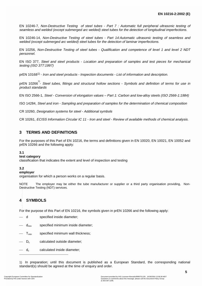
EN 10246-7, Non-Destructive Testing of steel tubes - Part 7 : Automatic full peripheral ultrasonic testing ofseamless and welded (except submerged arc welded) steel tubes for the detection of longitudinal imperfections.
EN 10246-14, Non-Destructive Testing of steel tubes - Part 14:Automatic ultrasonic testing of seamless andwelded (except submerged arc welded) steel tubes for the detection of laminar imperfections.
EN 10256, Non-Destructive Testing of steel tubes - Qualification and competence of level 1 and level 2 NDTpersonnel.
EN ISO 377, Steel and steel products - Location and preparation of samples and test pieces for mechanicaltesting (ISO 377:1997)
prEN 101681) , Iron and steel products - Inspection documents - List of information and description.
prEN 102661), Steel tubes, fittings and structural hollow sections - Symbols and definition of terms for use in
product standards
EN ISO 2566-1, Steel - Conversion of elongation values – Part 1: Carbon and low-alloy steels (ISO 2566-1:1984)
ISO 14284, Steel and iron - Sampling and preparation of samples for the determination of chemical composition
CR 10260, Designation systems for steel - Additional symbols
CR 10261, ECISS Information Circular IC 11 - Iron and steel - Review of available methods of chemical analysis.
3 TERMS AND DEFINITIONS
For the purposes of this Part of EN 10216, the terms and definitions given in EN 10020, EN 10021, EN 10052 andprEN 10266 and the following apply:
3.1test categoryclassification that indicates the extent and level of inspection and testing
3.2employerorganisation for which a person works on a regular basis.
NOTE The employer may be either the tube manufacturer or supplier or a third party organisation providing, Non-Destructive Testing (NDT) services.
4 SYMBOLS
For the purpose of this Part of EN 10216, the symbols given in prEN 10266 and the following apply:
� d specified inside diameter;
� dmin specified minimum inside diameter;
� Tmin specified minimum wall thickness;
� Dc calculated outside diameter;
� dc calculated inside diameter;
1) In preparation; until this document is published as a European Standard, the corresponding nationalstandard(s) should be agreed at the time of enquiry and order.
Copyright European Committee for Standardization Provided by IHS under license with CEN
Document provided by IHS Licensee=Borealis/9990751100, 10/28/2004 13:58:36 MDTQuestions or comments about this message: please call the Document Policy Groupat 303-397-2295.
--`,```,`,,`,``,`,```,`,,`,,-`-`,,`,,`,`,,`---

EN 10216-2:2002 (E)
6
� Tc calculated wall thickness;
� TC test category
5 CLASSIFICATION AND DESIGNATION
5.1 Classification
In accordance with the classification system in EN 10020, the steel grades P195GH, P235GH and P265GH areclassified as non-alloy quality steels and the other steel grades are classified as alloy special steels.
5.2 Designation
5.2.1 For the tubes covered by this Part of EN 10216 the steel designation consists of:
� the number of this Part of EN 10216;
plus either:
� the steel name in accordance with EN 10027-1 and CR 10260;
or:
the steel number allocated in accordance with EN 10027-2.
5.2.2 The steel name of non-alloy steel grades is designated by:
� the capital letter P for pressure purposes;
� the indication of the specified minimum yield strength at room temperature for wall thickness less than orequal to 16 mm, expressed in MPa (see Table 4):
� the symbols GH for elevated temperature.
5.2.3 The steel name of alloy steel grades is designated by the chemical composition (see Table 2) and thesymbols for the heat treatment, where specified in column 3 and footnote 3 of Table 1.
6 INFORMATION TO BE SUPPLIED BY THE PURCHASER
6.1 Mandatory information
The following information shall be supplied by the purchaser at the time of enquiry and order:
a) the quantity (mass or total length or number);
b) the term "tube";
c) the dimensions (outside diameter D and wall thickness T or a set of dimensions covered by Option 11) (seeTable 6);
d) the designation of the steel grade in accordance with this Part of EN 10216 (see 5.2);
e) the test category for non-alloy steel (see 9.3).
Copyright European Committee for Standardization Provided by IHS under license with CEN
Document provided by IHS Licensee=Borealis/9990751100, 10/28/2004 13:58:36 MDTQuestions or comments about this message: please call the Document Policy Groupat 303-397-2295.
--`,```,`,,`,``,`,```,`,,`,,-`-`,,`,,`,`,,`---

EN 10216-2:2002 (E)
7
6.2 Options
A number of options are specified in this Part of EN 10216 and these are listed below. In the event that thepurchaser does not indicate a wish to implement any of these options at the time of enquiry and order, the tubesshall be supplied in accordance with the basic specification (see 6.1).
1) Cold finishing (see 7.3.2).
2) Restriction on copper and tin content (see Table 2).
3) Product analysis (see 8.2.2).
4) Impact testing (see Table 4).
5) Longitudinal impact testing at -10° C for non-alloy steel grades (see Table 4).
6) Tensile testing at elevated temperature (see 8.3.2).
7) Selection of leak-tightness test method (see 8.4.2.1).
8) Non-Destructive Testing for test category 2 tubes for detection of transverse imperfections (see8.4.2.2).
9) Non-Destructive Testing for test category 2 tubes for detection of laminar imperfections (see 8.4.2.2).
10) Special ends preparation (see 8.6).
11) Set of dimensions other than D and T (see 8.7.1).
12) Exact lengths (see 8.7.3).
13) The type of inspection document other than the standard document (see 9.2.1).
14) Test pressure for hydrostatic leak-tightness test (see 11.8.1).
15) Wall thickness measurement away from the ends (see 11.9).
16) Non-Destructive Testing method (see 11.11.1).
17) Additional marking (see 12.2).
18) Protection (see 13).
6.3 Examples of an order
6.3.1 Example 1
100 t of seamless tube with an outside diameter of 168,3 mm, a wall thickness of 4,5 mm, in accordance with EN10216-2, made of steel grade P265GH, to test category 1 with a 3.1.C inspection certificate in accordance withEN 10204:
100 t - Tube - 168,3 x 4,5 - EN 10216-2 - P265GH - TC1 - Option 13: 3.1.C
6.3.2 Example 2
100 m of seamless tube with a minimum inside diameter of 240 mm, a minimum wall thickness of 40 mm inaccordance with Part of EN 10216, made of steel grade 10CrMo9-10, with a 3.1.C inspection certificate inaccordance with EN 10204:
100 m - Tube - dmin 240 x Tmin 40 - EN 10216-2 - 10CrMo9-10 - Option 13: 3.1.C
Copyright European Committee for Standardization Provided by IHS under license with CEN
Document provided by IHS Licensee=Borealis/9990751100, 10/28/2004 13:58:36 MDTQuestions or comments about this message: please call the Document Policy Groupat 303-397-2295.
--`,```,`,,`,``,`,```,`,,`,,-`-`,,`,,`,`,,`---
EN 10216-2:2002 (E)
8
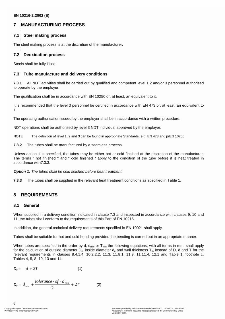
7 MANUFACTURING PROCESS
7.1 Steel making process
The steel making process is at the discretion of the manufacturer.
7.2 Deoxidation process
Steels shall be fully killed.
7.3 Tube manufacture and delivery conditions
7.3.1 All NDT activities shall be carried out by qualified and competent level 1,2 and/or 3 personnel authorisedto operate by the employer.
The qualification shall be in accordance with EN 10256 or, at least, an equivalent to it.
It is recommended that the level 3 personnel be certified in accordance with EN 473 or, at least, an equivalent toit.
The operating authorisation issued by the employer shall be in accordance with a written procedure.
NDT operations shall be authorised by level 3 NDT individual approved by the employer.
NOTE The definition of level 1, 2 and 3 can be found in appropriate Standards, e.g. EN 473 and prEN 10256
7.3.2 The tubes shall be manufactured by a seamless process.
Unless option 1 is specified, the tubes may be either hot or cold finished at the discretion of the manufacturer.The terms “ hot finished “ and “ cold finished “ apply to the condition of the tube before it is heat treated inaccordance with7.3.3.
Option 1: The tubes shall be cold finished before heat treatment.
7.3.3 The tubes shall be supplied in the relevant heat treatment conditions as specified in Table 1.
8 REQUIREMENTS
8.1 General
When supplied in a delivery condition indicated in clause 7.3 and inspected in accordance with clauses 9, 10 and11, the tubes shall conform to the requirements of this Part of EN 10216.
In addition, the general technical delivery requirements specified in EN 10021 shall apply.
Tubes shall be suitable for hot and cold bending provided the bending is carried out in an appropriate manner.
When tubes are specified in the order by d, dmin or Tmin the following equations, with all terms in mm, shall applyfor the calculation of outside diameter Dc, inside diameter dc and wall thickness Tc, instead of D, d and T for therelevant requirements in clauses 8.4.1.4, 10.2.2.2, 11.3, 11.8.1, 11.9, 11.11.4, 12.1 and Table 1, footnote c,Tables 4, 5, 8, 10, 13 and 14:
Dc = Td 2� (1)
Dc = Tdoftolerance
d 22
minmin �
��
� (2)
Copyright European Committee for Standardization Provided by IHS under license with CEN
Document provided by IHS Licensee=Borealis/9990751100, 10/28/2004 13:58:36 MDTQuestions or comments about this message: please call the Document Policy Groupat 303-397-2295.
--`,```,`,,`,``,`,```,`,,`,,-`-`,,`,,`,`,,`---

EN 10216-2:2002 (E)
9
dc = 2
minmin
doftoleranced
��
� (3)
Tc = 2
minmin
ToftoleranceT
��
� (4)
For tolerance see Tables 8, 9 and 10.
8.2 Chemical composition
8.2.1 Cast analysis
The cast analysis reported by the steel producer shall apply and conform to the requirements of Table 2.
NOTE When welding tubes produced in accordance with this Part of this EN 10216, account should be taken of the factthat the behaviour of the steel during and after welding is dependent not only on the steel, but also on the applied heattreatment and the conditions of preparing for and carrying out the welding.
8.2.2 Product analysis
Option 3 : Product analysis for the tubes shall be supplied.
Table 3 specifies the permissible deviations of the product analysis from the specified limits on cast analysisgiven in Table 2.
Copyright European Committee for Standardization Provided by IHS under license with CEN
Document provided by IHS Licensee=Borealis/9990751100, 10/28/2004 13:58:36 MDTQuestions or comments about this message: please call the Document Policy Groupat 303-397-2295.
--`,```,`,,`,``,`,```,`,,`,,-`-`,,`,,`,`,,`---
EN 10216-2:2002 (E)
10
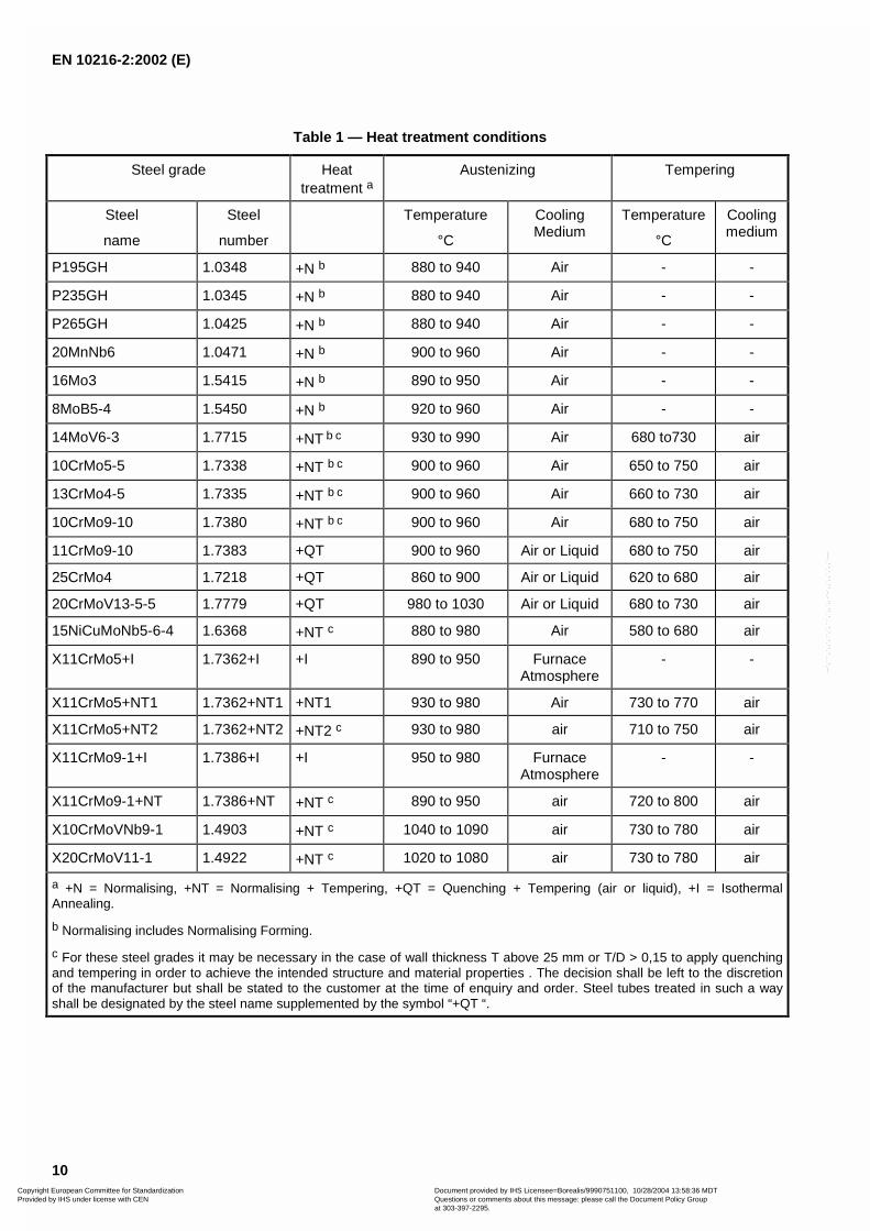
Table 1 — Heat treatment conditions
Steel grade Heattreatment a
Austenizing Tempering
Steel
name
Steel
number
Temperature
°C
CoolingMedium
Temperature
°C
Coolingmedium
P195GH 1.0348 +N b 880 to 940 Air - -
P235GH 1.0345 +N b 880 to 940 Air - -
P265GH 1.0425 +N b 880 to 940 Air - -
20MnNb6 1.0471 +N b 900 to 960 Air - -
16Mo3 1.5415 +N b 890 to 950 Air - -
8MoB5-4 1.5450 +N b 920 to 960 Air - -
14MoV6-3 1.7715 +NT b c 930 to 990 Air 680 to730 air
10CrMo5-5 1.7338 +NT b c 900 to 960 Air 650 to 750 air
13CrMo4-5 1.7335 +NT b c 900 to 960 Air 660 to 730 air
10CrMo9-10 1.7380 +NT b c 900 to 960 Air 680 to 750 air
11CrMo9-10 1.7383 +QT 900 to 960 Air or Liquid 680 to 750 air
25CrMo4 1.7218 +QT 860 to 900 Air or Liquid 620 to 680 air
20CrMoV13-5-5 1.7779 +QT 980 to 1030 Air or Liquid 680 to 730 air
15NiCuMoNb5-6-4 1.6368 +NT c 880 to 980 Air 580 to 680 air
X11CrMo5+I 1.7362+I +I 890 to 950 FurnaceAtmosphere
- -
X11CrMo5+NT1 1.7362+NT1 +NT1 930 to 980 Air 730 to 770 air
X11CrMo5+NT2 1.7362+NT2 +NT2 c 930 to 980 air 710 to 750 air
X11CrMo9-1+I 1.7386+I +I 950 to 980 FurnaceAtmosphere
- -
X11CrMo9-1+NT 1.7386+NT +NT c 890 to 950 air 720 to 800 air
X10CrMoVNb9-1 1.4903 +NT c 1040 to 1090 air 730 to 780 air
X20CrMoV11-1 1.4922 +NT c 1020 to 1080 air 730 to 780 air
a +N = Normalising, +NT = Normalising + Tempering, +QT = Quenching + Tempering (air or liquid), +I = IsothermalAnnealing.
b Normalising includes Normalising Forming.
c For these steel grades it may be necessary in the case of wall thickness T above 25 mm or T/D > 0,15 to apply quenchingand tempering in order to achieve the intended structure and material properties . The decision shall be left to the discretionof the manufacturer but shall be stated to the customer at the time of enquiry and order. Steel tubes treated in such a wayshall be designated by the steel name supplemented by the symbol “+QT “.
Copyright European Committee for Standardization Provided by IHS under license with CEN
Document provided by IHS Licensee=Borealis/9990751100, 10/28/2004 13:58:36 MDTQuestions or comments about this message: please call the Document Policy Groupat 303-397-2295.
--`,```,`,,`,``,`,```,`,,`,,-`-`,,`,,`,`,,`---

EN 10216-2:2002 (E)
11
Table 2 — Chemical composition (cast analysis) a, in % by mass
Steel grade C Si Mn Pmax
Smax
Cr Mo Ni Al tot Cu Nb Ti
max
V Cr+Cu
+Mo+Ni
Others
Steel name Steelnumber
195GH 1.0348 � 0,13 � 0,35 � 0,70 0,025 0,020 � 0,30 � 0,08 � 0,30� 0,020 b
� 0,30 c � 0,010d 0,040 d� 0,02 d � 0,70 -
P235GH 1.0345 � 0,16 � 0,35 � 1,20 0,025 0,020 � 0,30 � 0,08 � 0,30� 0,020 b
� 0,30 c� 0,010 d 0,040 d
� 0,02 d � 0,70 -
P265GH 1.0425 � 0,20 � 0,40 � 1,40 0,025 0,020 � 0,30 � 0,08 � 0,30 � 0,020 b� 0,30 c � 0,010 d 0,040 d
� 0,02 d � 0,70 -
20MnNb6 1.0471 � 0,22 0,15to
0,35
1,00to
1,50
0,025 0,020 - - - � 0,060 � 0,30 c 0,015to
0,10
- - - -
16Mo3 1.5415 0,12to
0,20 e
� 0,35 0,40to
0,90
0,025 0,020 � 0,30 0,25to
0,35
� 0,30 � 0,040� 0,30 c - - - - -
8MoB5-4 1.5450 0,06to
0,10
0,10to
0,35
0,60to
0,80
0,025 0,020 � 0,20 0,40to
0,50
- � 0,060 � 0,30 c - 0,060 - - B = 0,002to
0,006
14MoV63 1.7715 0,10to
0,15
0,15to
0,35
0,40to
0,70
0,025 0,020 0,30to
0,60
0,50to
0,70
� 0,30 � 0,040� 0,30 c - - 0,22
to0,28
- -
10CrMo5-5 1.7338 � 0,15 0,50to
1,00
0,30to
0,60
0,025 0,020 1,00to
1,50
0,45to
0,65
� 0,30 � 0,040 � 0,30 c - - - - -
13CrMo4-5 1.7335 0,10to
0,17 e
� 0,35 0,40to
0,70
0,025 0,020 0,70to
1,15
0,40to
0,60
� 0,30 � 0,040� 0,30 c - - - - -
10CrM09-10 1.7380 0,08to
0,14
� 0,50 0,30to
0,70
0,025 0,020 2,00to
2,50
0,90to
1,10
� 0,30 � 0,040� 0,30 c - - . - -
11CrMo9-10 1.7383 0,08to
0,15
� 0,50 0,40to
0,80
0,025 0,020 2,00to
2,50
0,90to
1,10
� 0,30 � 0,040 � 0,30 c - - . - -
Copyright E
uropean Com
mittee for S
tandardization P
rovided by IHS
under license with C
EN
Docum
ent provided by IHS
Licensee=B
orealis/9990751100, 10/28/2004 13:58:36 MD
TQ
uestions or comm
ents about this message: please call the D
ocument P
olicy Group
at 303-397-2295.
--`,```,`,,`,``,`,```,`,,`,,-`-`,,`,,`,`,,`---

EN 10216-2:2002 (E)
12
Table 2 (continued)
Steel gradeC Si Mn P
maxS
maxCr Mo Ni Al tot Cu Nb Ti V Cr+Cu
+Mo+Ni
Others
Steel name Steel number
25CrMo4 1.7218 0,22to
0,29
� 0,40 0,60to
0,90
0,025 0,020 0,90to
1,20
0,15to
0,30
� 0,30 � 0,040 � 0,30 c - - - - -
20CrMoV13-5-5 1.7779 0,17to
0,23
0,15to
0,35
0,30to
0,50
0,025 0,020 3,00 to
3,30
0,50to
0,60
� 0,30 � 0,040� 0,30 c - - 0,45
to0,55
- -
15NiCuMoNb5-6-4 1.6368 � 0,17 0,25to
0,50
0,80to
1,20
0,025 0,020 � 0,30 0,25to
0,50
1,00to
1,30
� 0,050 0,50to
0,80
0,015to
0,045
- - - -
X11CrMo5+IX11CrMo5+NT1X11CrMo5+NT2
1.7362+I1.7362+NT11.7362+NT2
0,08to
0,15
0,15to
0,50
0,30to
0,60
0,025 0,020 4,00to
6,00
0,45to
0,65
� 0,040 � 0,30c
X11CrMo9-1+IX11CrMo9-1+NT
1.7386+I1.7386+NT
0,08to
0,15
0,25to
1,00
0,30to
0,60
0,025 0,020 8,00to
10,00
0,90to
1.10
� 0,040� 0,30 c
X10CrMoVNb9-1 1.4903 0,08to
0,12
0,20to
0,50
0,30to
0,60
0,020 0,010 8,00to
9,50
0,85to
1,05
� 0,40 � 0,040 � 0,30 c 0,06to
0,10
- 0,18to
0,25
- N = 0,030to
0,070
X20CrMoV11-1 1.4922 0,17to
0,23f
0,15to
0,50
� 1,00 0,025 0,020 10,00to
12,50
0,80to
1,20
0,30to
0,80
� 0,040� 0,30 c - - 0,25
to0.35
- -
a Elements not included in this Table shall not be intentionally added to the steel without the agreement of the purchaser, except for elements which may be added for finishing the cast. Allappropriate measures shall be taken to prevent the addition of undesirable elements from scrap or other materials used in the steel making process.
b This requirement is not applicable provided the steel contains a sufficient amount of other nitrogen binding elements which shall be reported. When using titanium, the producer shall verifythat (Al+Ti/2)�0,020%
c Option 2: In order to facilitate subsequent forming operations, an agreed maximum copper content lower than indicated and an agreed specified maximum tin content shall apply
d The content of these elements need not to be reported unless intentionally added to the cast.
e For wall thickness � 30 mm the carbon content may be increased by 0,02 % for cast and product analysis.
f The upper carbon value of 0,23 % shall not be exceeded for product analysis.
Copyright E
uropean Com
mittee for S
tandardization P
rovided by IHS
under license with C
EN
Docum
ent provided by IHS
Licensee=B
orealis/9990751100, 10/28/2004 13:58:36 MD
TQ
uestions or comm
ents about this message: please call the D
ocument P
olicy Group
at 303-397-2295.
--`,```,`,,`,``,`,```,`,,`,,-`-`,,`,,`,`,,`---

EN 10216-2:2002 (E)
13
Table 3 — Permissible deviations of the product analysis from specified limits on cast analysis givenin Table 2
Element Limiting value for the cast analysis inaccordance with Table 2
% by mass
Permissible deviation of the productanalysis
% by mass
C � 0,29 � 0,02
� 0,40 � 0,05Si
� 0,40 to � 1,00 � 0,06
� 1,00 � 0,05Mn
� 1,00 to � 1,50 � 0,10
P � 0,025 + 0,005
� 0,010 + 0,003S
� 0,010 � 0,020 + 0,005
Al � 0,060 � 0,005
B � 0,006 � 0,001
� 1,00 � 0,05
� 1,00 to � 10,00 � 0,10Cr
� 10,00 to � 12,50 � 0,15
Cu � 0,80 � 0,05
� 0,35 � 0,03Mo
� 0,35 to � 1,20 � 0,04
N � 0,070 � 0,01
Nb � 0,10 � 0,005
� 0,35 � 0,05Ni
� 0,35 to � 1,30 � 0,07
Ti � 0,060 + 0,010
� 0,10 + 0,01V
� 0,10 to � 0,55 � 0,03
8.3 Mechanical properties
8.3.1 Mechanical properties at and below room temperature
The mechanical properties at and below room temperature of the tubes shall conform to the requirements inTable 4 and in clauses 11.3, 11.4, 11.5 and 11.6.
8.3.2 Proof strength at elevated temperature
The minimum proof strength Rp0,2 values at elevated temperature are given in Table 5.
Option 6: Proof strength Rp0,2 shall be verified. The test temperature shall be specified at the time of enquiryand order.
Copyright European Committee for Standardization Provided by IHS under license with CEN
Document provided by IHS Licensee=Borealis/9990751100, 10/28/2004 13:58:36 MDTQuestions or comments about this message: please call the Document Policy Groupat 303-397-2295.
--`,```,`,,`,``,`,```,`,,`,,-`-`,,`,,`,`,,`---

EN 10216-2:2002 (E)
14
8.3.3 Creep rupture strength
The creep rupture strength values are given in annex A for information.
Copyright European Committee for Standardization Provided by IHS under license with CEN
Document provided by IHS Licensee=Borealis/9990751100, 10/28/2004 13:58:36 MDTQuestions or comments about this message: please call the Document Policy Groupat 303-397-2295.
--`,```,`,,`,``,`,```,`,,`,,-`-`,,`,,`,`,,`---

EN 10216-2:2002 (E)
15
Table 4 — Mechanical properties
Steel grade Tensile properties at room temperature Impact properties a b
Steel name Steel
number
Upper yield strength or proof strength
ReH or Rp 0,2 for Wall Thickness T
min.
Tensile
Strength
Rm
Elongation
A min.
% a
Minimum average absorbed energy KV
J
at a temperature of
°C
T � 16 16 � T � 40 40 � T � 60 60 � T � 100 l t l t
MPa * MPa * MPa * MPa * MPa * 20 0 -10 20 0
P195GH 1.0348 195 - - - 320 to 440 27 25 - 40 c 28 d - 27 c
P235GH 1.0345 235 225 215 - 360 to 500 25 23 - 40 c 28 d - 27 c
P265GH 1.0425 265 255 245 - 410 to 570 23 21 - 40 c 28 d - 27 c
20MnNb6 1.0471 355 345 335 - 500 to 650 22 20 . 40 c - - 27 c
16Mo3 1.5415 280 270 260 - 450 to 600 22 20 40 c - - 27 c -
8MoB5-4 1.5450 400 - - - 540 to 690 19 17 40 c - - 27 c -
14MoV6-3 1.7715 320 320 310 - 460 to 610 20 18 40 c f - - 27 c -
10CrMo5-5 1.7338 275 275 265 - 410 to 560 22 20 40 c - - 27 c -
13CrMo4-5 1.7335 290 290 280 - 440 to 590 22 20 40 c - - 27 c -
10CrMo9-10 1.7380 280 280 270 - 480 to 630 22 20 40 c - - 27 c -
11CrMo9-10 1.7383 355 355 355 - 540 to 680 20 18 40 c - - 27 c -
25CrMo4 1.7218 345 345 345 - 540 to 690 18 15 40 c f - - 27 c -
20CrMoV13-5-5 1.7779 590 590 590 - 740 to 880 16 14 40 c f - - 27 c -
15NiCuMoNb5-6-4 1.6368 440 440 440 440 e 610 to 780 19 17 40 c f - - 27 c -
Copyright E
uropean Com
mittee for S
tandardization P
rovided by IHS
under license with C
EN
Docum
ent provided by IHS
Licensee=B
orealis/9990751100, 10/28/2004 13:58:36 MD
TQ
uestions or comm
ents about this message: please call the D
ocument P
olicy Group
at 303-397-2295.
--`,```,`,,`,``,`,```,`,,`,,-`-`,,`,,`,`,,`---

EN 10216-2:2002 (E)
16
Table 4 (continued)
Steel name Steel
number
Upper yield strength or proof strength
ReH or Rp 0,2 for Wall Thickness T
min.
Tensile
Strength
Rm
Elongation
A min.
% a
Minimum average absorbed energy KV
J
at a temperature of
°C
T � 16 16 � T � 40 40 � T � 60 60 � T � 100 l t l t
MPa * MPa * MPa * MPa * MPa * 20 0 -10 20 0
X11CrMo5+I 1.7362+I 175 175 175 175 430 to 580 22 20 40 c - - 27 c -
X11CrMo5+NT1 1.7362+NT1 280 280 280 280 480 to 640 20 18 40 c - - 27 c -
X11CrMo5+NT2 1.7362+NT2 390 390 390 390 570 to 740 18 16 40 c - - 27 c -
X11CrMo9-1+I 1.7386+I 210 210 210 - 460 to 640 20 18 40 c - - 27 c -
X11CrMo9-1+NT 1.7386+NT 390 390 390 - 590 to 740 18 16 40 c - - 27 c -
X10CrMoVNb9-1 1.4903 450 450 450 450 630 to 830 19 17 40 c f - - 27 c -
X20CrMoV11-1 1.4922 490 490 490 490 690 to 840 17 14 40 c f - - 27 c
a l = longitudinal t = transverse
b To be verified when options 4 and/or 5 are/is specified, unless footnote f) applies.
c Option 4: Impact energy shall be verified.
d Option 5: Longitudinal impact energy shall be verified.
e For wall thickness 60 mm� T � 80 mm.
f Impact test mandatory for wall thickness T � 16 mm.
* MPa = 1 N/mm2
Copyright E
uropean Com
mittee for S
tandardization P
rovided by IHS
under license with C
EN
Docum
ent provided by IHS
Licensee=B
orealis/9990751100, 10/28/2004 13:58:36 MD
TQ
uestions or comm
ents about this message: please call the D
ocument P
olicy Group
at 303-397-2295.
--`,```,`,,`,``,`,```,`,,`,,-`-`,,`,,`,`,,`---

EN 10216-2:2002 (E)
17
Table 5 — Minimum proof strength R p0,2 at elevated temperature
Steel grade Wall thickness
mm
Minimum proof strength Rp0,2 MPa a
at temperature of °C
Steel name Steel number 100 150 200 250 300 350 400 450 500 550 600
P195GH 1.0348 �16 175 165 150 130 113 102 94 - - - -
P235GH 1.0345 � 60 198 187 170 150 132 120 112 108 - - -
P265GH 1.0425 � 60 226 213 192 171 154 141 134 128 - - -
20MnNb6 1.0471 � 60 312 292 264 241 219 200 186 174 - - -
16Mo3 1.5415 � 60 243 237 224 205 173 159 156 150 146 - -
8MoB5-4 1.5450 � 16 368 368 368 368 368 368 368 - - - -
14MoV6-3 1.7715 � 60 282 276 267 241 225 216 209 203 200 197 -
10CrMo5-5 1.7338 � 60 240 228 219 208 165 156 148 144 143 - -
13CrMo4-5 1.7335 � 60 264 253 245 236 192 182 174 168 166 - -
10CrMo9-10 1.7380 � 60 249 241 234 224 219 212 207 193 180 - -
11CrMo9-10 1.7383 � 60 323 312 304 296 289 280 275 257 239 - -
25CrMo4 1.7218 � 60 - 315 305 295 285 265 225 185 - - -
20CrMoV13-5-5 1.7779 � 60 - 575 570 560 550 510 470 420 370 - -
15NiCuMoNb5-6-4 1.6368 � 80 422 412 402 392 382 373 343 304 - - -
X11CrMo5+I 1.7362+I � 100 156 150 148 147 145 142 137 129 116 - -
X11CrMo5+NT1 1.7362+NT1 � 100 245 237 230 223 216 206 196 181 167 - -
X11CrMo5+NT2 1.7362+NT2 � 100 366 350 334 332 309 299 289 280 265 - -
X11CrMo9-1+I 1.7386+I � 60 187 186 178 177 175 171 164 153 142 120 -
X11CrMo9-1+NT 1.7386+NT � 60 363 348 334 330 326 322 316 311 290 235 -
X10CrMoVNb9-1 1.4903 � 100 410 395 380 370 360 350 340 320 300 270 215
X20CrMoV11-1 1.4922 � 100 - - 430 415 390 380 360 330 290 250
a 1 MPa = 1 N/mm 2
Copyright E
uropean Com
mittee for S
tandardization P
rovided by IHS
under license with C
EN
Docum
ent provided by IHS
Licensee=B
orealis/9990751100, 10/28/2004 13:58:36 MD
TQ
uestions or comm
ents about this message: please call the D
ocument P
olicy Group
at 303-397-2295.
--`,```,`,,`,``,`,```,`,,`,,-`-`,,`,,`,`,,`---
EN 10216-2:2002 (E)
18
8.4 Appearance and internal soundness
8.4.1 Appearance
8.4.1.1 The tubes shall be free from external and internal surface defects that can be detected by visualexamination.
8.4.1.2 The internal and external surface finish of the tubes shall be typical of the manufacturing processand, where applicable, the heat treatment employed. Normally the finish and surface condition shall be suchthat any surface imperfections requiring dressing can be identified.
8.4.1.3 It shall be permissible to dress, only by grinding or machining, surface imperfections provided that,after doing so, the wall thickness in the dressed area is not less than the specified minimum wall thickness. Alldressed areas shall blend smoothly into the contour of the tube.
8.4.1.4 Any surface imperfection, which is demonstrated to be deeper than 5 % of the wall thickness T or 3mm whichever is the smaller, shall be dressed.
This requirement does not apply to surface imperfection with a depth equal or less 0,3 mm
8.4.1.5 Surface imperfections which encroach on the specified minimum wall thickness shall be considereddefects and tubes containing these shall be deemed not to conform to this Part of EN 10216.
8.4.2 Internal soundness
8.4.2.1 Leak Tightness
The tubes shall pass a hydrostatic test (see 11.8.1) or electromagnetic test (see 11.8.2) for leak-tightness.
Unless option 7 is specified, the choice of the test method is at the discretion of the manufacturer.
Option 7: The test method for verification of leak-tightness in accordance with 11.8.1 or 11.8.2 is specified bythe purchaser.
8.4.2.2 Non-Destructive Testing
The tubes of test category 2 shall be subjected to a non-destructive testing for the detection of longitudinalimperfections, in accordance with11.11.1.
Option 8: The tubes of test category 2 shall subjected to a non-destructive testing for the detection oftransverse imperfections in accordance with11.11.2.
Option 9: The tubes of test category 2 shall be subjected to a non-destructive testing for the detection of thelaminar imperfections in accordance with11.11.3.
8.5 Straightness
The deviation from straightness of any tube length L shall not exceed 0,0015 L. Deviations from straightnessover any one metre length shall not exceed 3 mm.
8.6 Preparation of ends
Tubes shall be delivered with square cut ends. The ends shall be free from excessive burrs.
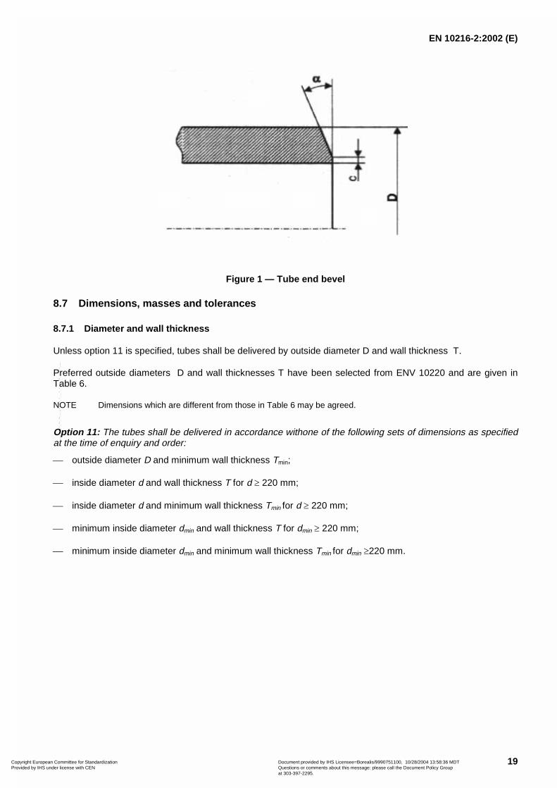
Option10: The tubes shall be delivered with bevelled ends (see figure 1). The bevel shall have an angle � of
30° ��
�
50 with a root face C of 1,6 mm � 0,8 mm, except that for wall thickness T greater than 20 mm, an agreed
alternative bevel may be specified
Copyright European Committee for Standardization Provided by IHS under license with CEN
Document provided by IHS Licensee=Borealis/9990751100, 10/28/2004 13:58:36 MDTQuestions or comments about this message: please call the Document Policy Groupat 303-397-2295.
--`,```,`,,`,``,`,```,`,,`,,-`-`,,`,,`,`,,`---
EN 10216-2:2002 (E)
19
Figure 1 — Tube end bevel
8.7 Dimensions, masses and tolerances
8.7.1 Diameter and wall thickness
Unless option 11 is specified, tubes shall be delivered by outside diameter D and wall thickness T.
Preferred outside diameters D and wall thicknesses T have been selected from ENV 10220 and are given inTable 6.
NOTE Dimensions which are different from those in Table 6 may be agreed.
Option 11: The tubes shall be delivered in accordance withone of the following sets of dimensions as specifiedat the time of enquiry and order:
� outside diameter D and minimum wall thickness Tmin;
� inside diameter d and wall thickness T for d � 220 mm;
� inside diameter d and minimum wall thickness Tmin for d � 220 mm;
� minimum inside diameter dmin and wall thickness T for dmin � 220 mm;
� minimum inside diameter dmin and minimum wall thickness Tmin for dmin �220 mm.
Copyright European Committee for Standardization Provided by IHS under license with CEN
Document provided by IHS Licensee=Borealis/9990751100, 10/28/2004 13:58:36 MDTQuestions or comments about this message: please call the Document Policy Groupat 303-397-2295.
--`,```,`,,`,``,`,```,`,,`,,-`-`,,`,,`,`,,`---

EN 10216-2:2002 (E)
20
Table 6 — Preferred dimensionsdimensions in mm
Outside diameter D
Series a Wall thickness T1 2 3 1,6 1,8 2 2,3 2,6 2,9 3,2 3,6 4 4,5 5 5,6 6,3 7,1 8 8,8 10 11 12,5 14,2
10,212
12,713,5
1416
17,218
1920
21,322
2525,4
26,930
31,832
33,735
3840
42,444,5
48,351
5457
60,363,570
7376,1
82,588,9
101,6108
114,3127133
139,7141,3152,4159
168,3177,8193,7
219,1244,5
273323,9355,6406,4457508
559610
660711
Copyright European Committee for Standardization Provided by IHS under license with CEN
Document provided by IHS Licensee=Borealis/9990751100, 10/28/2004 13:58:36 MDTQuestions or comments about this message: please call the Document Policy Groupat 303-397-2295.
--`,```,`,,`,``,`,```,`,,`,,-`-`,,`,,`,`,,`---

EN 10216-2:2002 (E)
21
Table 6 (Continued)dimensions in mm
Outside diameterD
Series aWall thickness T
1 2 3 16 17,5 20 22,2 25 28 30 32 36 40 45 50 55 60 65 70 80 90 100
10,212
12,713,5
1416
17,218
1920
21,322
2525,4
26,930
31,832
33,735
3840
42,444,5
48,351
5457
60,363,5
7073
76,1
82,5
88,9
101,6
108
114,3
127
133139,7
141,3
152,4159
168,3
177,8
193,7
219
244,5273
323,9355,6406,4457508
559610
660
711
a series 1 = diameter for which all the accessories needed for the construction of piping system are standardised;series 2 = diameter for which not all the accessories are standardised ;series 3 = diameter for special application for which very few standardised accessories exist.
Copyright European Committee for Standardization Provided by IHS under license with CEN
Document provided by IHS Licensee=Borealis/9990751100, 10/28/2004 13:58:36 MDTQuestions or comments about this message: please call the Document Policy Groupat 303-397-2295.
--`,```,`,,`,``,`,```,`,,`,,-`-`,,`,,`,`,,`---
EN 10216-2:2002 (E)
22
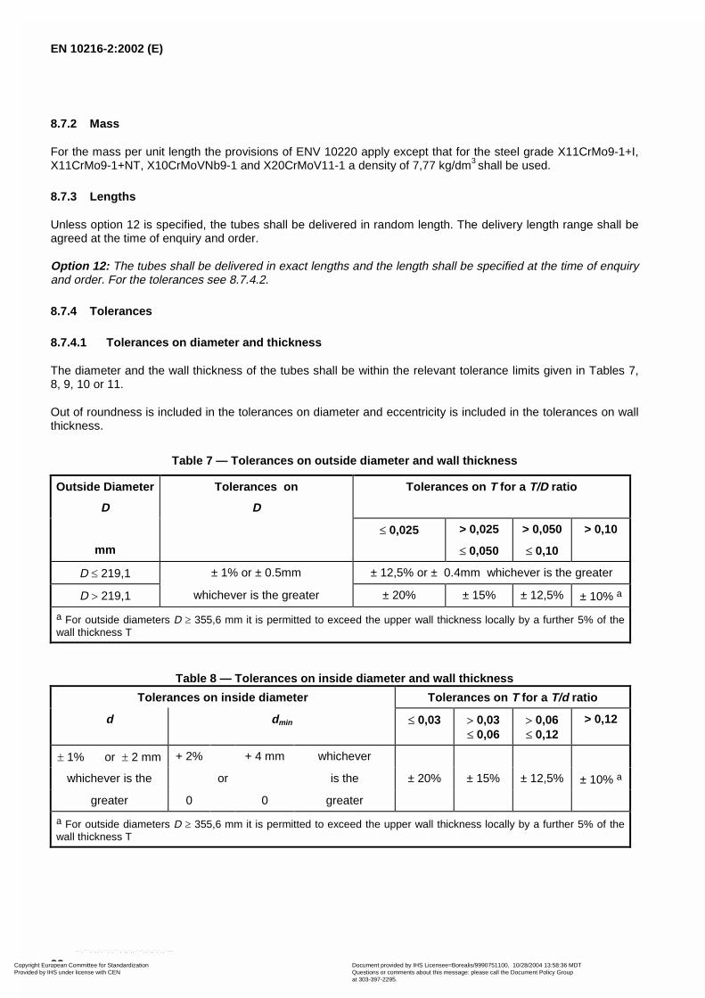
8.7.2 Mass
For the mass per unit length the provisions of ENV 10220 apply except that for the steel grade X11CrMo9-1+I,X11CrMo9-1+NT, X10CrMoVNb9-1 and X20CrMoV11-1 a density of 7,77 kg/dm3 shall be used.
8.7.3 Lengths
Unless option 12 is specified, the tubes shall be delivered in random length. The delivery length range shall beagreed at the time of enquiry and order.
Option 12: The tubes shall be delivered in exact lengths and the length shall be specified at the time of enquiryand order. For the tolerances see 8.7.4.2.
8.7.4 Tolerances
8.7.4.1 Tolerances on diameter and thickness
The diameter and the wall thickness of the tubes shall be within the relevant tolerance limits given in Tables 7,8, 9, 10 or 11.
Out of roundness is included in the tolerances on diameter and eccentricity is included in the tolerances on wallthickness.
Table 7 — Tolerances on outside diameter and wall thickness
Outside Diameter
D
Tolerances on
D
Tolerances on T for a T/D ratio
mm
� 0,025 > 0,025
� 0,050
> 0,050
� 0,10
> 0,10
D � 219,1 ± 1% or ± 0.5mm ± 12,5% or ± 0.4mm whichever is the greater
D � 219,1 whichever is the greater ± 20% ± 15% ± 12,5% ± 10% a
a For outside diameters D � 355,6 mm it is permitted to exceed the upper wall thickness locally by a further 5% of thewall thickness T
Table 8 — Tolerances on inside diameter and wall thickness
Tolerances on inside diameter Tolerances on T for a T/d ratio
d dmin � 0,03 � 0,03� 0,06
� 0,06� 0,12
> 0,12
� 1% or � 2 mm + 2% + 4 mm whichever
whichever is the or is the ± 20% ± 15% ± 12,5% ± 10% a
greater 0 0 greater
a For outside diameters D � 355,6 mm it is permitted to exceed the upper wall thickness locally by a further 5% of thewall thickness T
Copyright European Committee for Standardization Provided by IHS under license with CEN
Document provided by IHS Licensee=Borealis/9990751100, 10/28/2004 13:58:36 MDTQuestions or comments about this message: please call the Document Policy Groupat 303-397-2295.
--`,```,`,,`,``,`,```,`,,`,,-`-`,,`,,`,`,,`---

EN 10216-2:2002 (E)
23
Table 9 — Tolerances on outside diameter and minimum wall thickness
Outside diameter Tolerances on Tolerances on Tmin for a Tmin /D ratio
Dmm
D � 0,02 � 0,02� 0,04
� 0,04� 0,09
> 0,09
D � 219,1 ± 1% or ± 0.5mm + 28%0
or + 0.8 mm0
whichever is thegreater
D � 219,1 whichever is the greater + 50%
0
+ 35%
0
+ 28%
0
+ 22% a
0
a For outside diameters D � 355,6 mm it is permitted to exceed the upper wall thickness locally by a further 5% of thewall thickness T
Table 10 — Tolerances on inside diameter and minimum wall thickness
Tolerances
on inside diameter
Tolerances on Tmin for aTmin /d ratio
d dmin � 0,05 � 0,05
� 0,1
> 0,1
� 1% or � 2 mmwhichever is the greater
+2%0
or + 4 mm0
whichever is thegreater
+ 35%0
+ 28%0
+ 22% a
0
a For outside diameters D � 355,6 mm it is permitted to exceed the upper wall thickness locally by a further 5% of thewall thickness T
Table 11 — Tolerances on outside diameter and wall thickness for tube ordered cold finished
Tolerance on D Tolerance on T
� 0,5% or � 0,3 mm
whichever is the greater
� 10% or � 0,2 mm
whichever is the greater
8.7.4.2 Tolerances on exact lengths
The tolerances for exact lengths shall be as given in Table 12.
Table 12 — Tolerances on exact lengths
Dimension in mm
Length L Tolerance on exact length
L � 6000 +100
6000 < L � 12 000 +150
L � 12 000 + by agreement0
Copyright European Committee for Standardization Provided by IHS under license with CEN
Document provided by IHS Licensee=Borealis/9990751100, 10/28/2004 13:58:36 MDTQuestions or comments about this message: please call the Document Policy Groupat 303-397-2295.
--`,```,`,,`,``,`,```,`,,`,,-`-`,,`,,`,`,,`---

EN 10216-2:2002 (E)
24
9 INSPECTION
9.1 Types of inspection
Conformity to the requirements of the order, for tubes in accordance with this Part of EN 10216, shall bechecked by specific inspection.
9.2 Inspection documents
9.2.1 Types of inspection documents
Unless option 13 is specified, an inspection certificate 3.1.B, in accordance with EN 10204, shall be issued.
Option 13: One of the inspection documents 3.1.A, 3.1.C or 3.2 in accordance with EN 10204 shall be issued
If an inspection document 3.1.A, 3.1.C or 3.2 is specified, the purchaser shall notify the manufacturer of thename and address of the organisation or person who is to carry out the inspection and produce the inspectiondocument . In the case of inspection report 3.2 it shall be agreed which party shall issue the certificate.
9.2.2 Content of inspection documents
The content of the inspection document shall be in accordance withprEN 10168.
The inspection certificate or inspection report shall contain the following codes and information :
� A - commercial transactions and parties involved;
� B - description of products to which the inspection document applies;
� C02-C03 - direction of the test pieces and testing temperature;
� C10-C13 - tensile test;
� C40-C43 - impact test if applicable;
� C60-C69 - other tests (e.g. flattening);
� C71-C92 - chemical composition on cast analysis (product analysis if applicable);
� D01 - marking and identification, surface appearance, shape and dimensional properties;
� D02-D99 - leak-tightness test, NDT, material identification if applicable;
� Z - validation.
9.3 Summary of inspection and testing
Non-alloy steel tubes shall be inspected and tested in accordance with test category 1 or test category 2 asspecified at the time of inquiry and order (see 6.1).
Alloy steel tubes shall be inspected and tested in accordance with test category 2 (see Table 13).
Inspection and testing to be carried out are summarised in Table 13.
Copyright European Committee for Standardization Provided by IHS under license with CEN
Document provided by IHS Licensee=Borealis/9990751100, 10/28/2004 13:58:36 MDTQuestions or comments about this message: please call the Document Policy Groupat 303-397-2295.
--`,```,`,,`,``,`,```,`,,`,,-`-`,,`,,`,`,,`---

EN 10216-2:2002 (E)
25
Table 13 — Summary of inspection and testing
Test category(TC)Type of inspection and test
Frequency ofTesting
Refer to
1 2
Cast analysis One per cast 8.2.1 - 11.1 X X
Tensile test at room temperature 8.3.1 - 11.2.1 X X
Flattening test for D � 600 mm and T/D ratio � 0,15 but T � 40 mm
or a
Ring tensile test for D � 150 mm and T � 40 mm
8.3 - 11.3 -11.4 X X
Drift expanding test for D � 150 mm and T � 10 mm
or a b
Ring expanding test for D � 114.3 mm and T � 12,5 mm
8.3 - 11.5 - 11.6 X X
Impact test at 20° C for Group A c
One per
sample tube
8.3 - 11.7 X X
Leak tightness test Each tube 8.4.2.1 - 11.8 X X
Dimensional inspection 8.7.1 - 11.9 X X
Visual examination 11.10 X X
NDT for the detection of longitudinal imperfections Each 8.4.2.2 - 11.11.1 -- X
Mandatorytests
Material identification of alloy steels tube 11.12 X X
Product analysis (Option 3) One per cast 8.2.2 - 11.1 X X
Tensile test at elevated temperature (Option 6)
One per castand same heat
treatmentcondition
8.3.2 - 11.2.2 X X
Impact test for Group B c (Option 4) One per 8.3 - 11.7 X X
Longitudinal impact test at-10°C for non-alloy steel grades (Option 5) sample tube 8.3 - 11.7 X X
Wall thickness measurement away from tube ends (Option 15) 8.7.1 - 11.9 X X
NDT for the detection of transverse imperfections (Option 8) Each 8.4.2.2 - 11.11.2 -- X
Optional
tests
NDT for the detection of laminar imperfections (Option 9) tube 8.4.2.2 - 11.11.3 -- X
a The choice of flattening or ring tensile test and of drift expanding test or ring expanding test is at the manufacturer’sdiscretion.
b For steel grades X10CrMoVNb9-1 and X20CrMoV11-1 tubes, the flattening or ring tensile test and the drift expanding testor ring expanding test shall be carried out at one end of 20 % of the tubes of each test unit.
c Group A: tubes having wall thickness T � 16 mm manufactured from steel grades 14MoV6-3, 25CrMo4, 20CrMoV13-5-5, 15NiCuMoNb5-6-4, X10CrMoVNb9-1 and X20CrMoV11-1
Group B: All tubes except group A.
10 SAMPLING
10.1 Frequency of tests
10.1.1 Test unit
For normalised formed tubes a test unit shall comprise tubes of the same specified diameter and wall thickness,the same steel grade, the same cast, the same manufacturing process.
Copyright European Committee for Standardization Provided by IHS under license with CEN
Document provided by IHS Licensee=Borealis/9990751100, 10/28/2004 13:58:36 MDTQuestions or comments about this message: please call the Document Policy Groupat 303-397-2295.
--`,```,`,,`,``,`,```,`,,`,,-`-`,,`,,`,`,,`---

EN 10216-2:2002 (E)
26
For tubes which are furnace heat treated a test unit shall comprise tubes of the same specified diameter andwall thickness, the same steel grade, the same cast, the same manufacturing process, subjected to the samefinishing treatment in a continuous furnace or heat treated in the same furnace charge in a batch-type furnace.
The number of tubes per test unit shall conform to Table 14.
Table 14 — Number of tubes per test unit
Outside diameter D
mm
Maximum number of tubes per test unit
D � 114,3 200
114,3 � D � 323,9 100
D � 323,9 50
10.1.2 Number of sample tubes per test unit
The following number of sample tubes shall be selected from each test unit :
� test category 1: one sample tube;
� test category 2: two sample tubes; when the total number of tubes is less than 20, only one sample tube
10.2 Preparation of samples and test pieces
10.2.1 Selection and preparation of samples for product analysis
Samples for product analysis shall be taken from the test pieces or samples for mechanical testing or from thewhole thickness of the tube at the same location as the mechanical test samples, in accordance with ISO14284.
10.2.2 Location, orientation and preparation of samples and test pieces for mechanical test
10.2.2.1 General
Samples and test pieces shall be taken at the tube ends and in accordance with the requirements of EN ISO377.
10.2.2.2 Test pieces for tensile tests
The test pieces for the tensile tests at room temperature shall be prepared in accordance with EN 10002-1.
The test piece for the tensile tests at elevated temperature shall be prepared in accordance with EN 10002-5.
At the manufacturer's discretion:
� for tubes with an outside diameter D � 219,1 mm the test piece shall be either a full tube section or a stripsection and shall be taken in a direction longitudinal to the axis of the tube;
� for tubes with an outside diameter D � 219,1 mm the test piece shall either a machined test piece withcircular cross section from an unflattened sample or a strip section and be taken in a direction eitherlongitudinal or transverse to the axis of the tube.
10.2.2.3 Test pieces for flattening test, ring tensile test, drift expanding test and ring expanding test
The test pieces for the flattening test, ring tensile test, drift expanding test and the ring expanding test shallconsist of a full tube section in accordance with EN 10233, EN 10237, EN 10234 or EN 10236 respectively.
Copyright European Committee for Standardization Provided by IHS under license with CEN
Document provided by IHS Licensee=Borealis/9990751100, 10/28/2004 13:58:36 MDTQuestions or comments about this message: please call the Document Policy Groupat 303-397-2295.
--`,```,`,,`,``,`,```,`,,`,,-`-`,,`,,`,`,,`---
EN 10216-2:2002 (E)
27
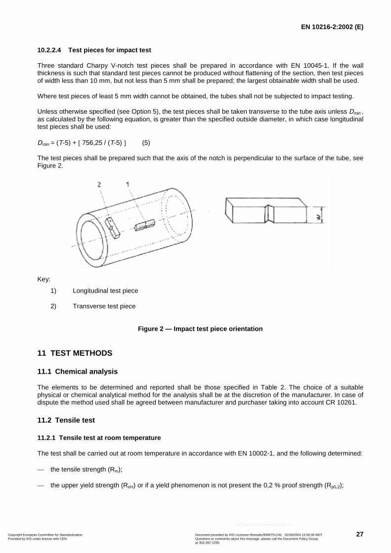
10.2.2.4 Test pieces for impact test
Three standard Charpy V-notch test pieces shall be prepared in accordance with EN 10045-1. If the wallthickness is such that standard test pieces cannot be produced without flattening of the section, then test piecesof width less than 10 mm, but not less than 5 mm shall be prepared; the largest obtainable width shall be used.
Where test pieces of least 5 mm width cannot be obtained, the tubes shall not be subjected to impact testing.
Unless otherwise specified (see Option 5), the test pieces shall be taken transverse to the tube axis unless Dmin ,as calculated by the following equation, is greater than the specified outside diameter, in which case longitudinaltest pieces shall be used:
Dmin = (T-5) + 756,25 / (T-5) (5)
The test pieces shall be prepared such that the axis of the notch is perpendicular to the surface of the tube, seeFigure 2.
Key:
1) Longitudinal test piece
2) Transverse test piece
Figure 2 — Impact test piece orientation
11 TEST METHODS
11.1 Chemical analysis
The elements to be determined and reported shall be those specified in Table 2. The choice of a suitablephysical or chemical analytical method for the analysis shall be at the discretion of the manufacturer. In case ofdispute the method used shall be agreed between manufacturer and purchaser taking into account CR 10261.
11.2 Tensile test
11.2.1 Tensile test at room temperature
The test shall be carried out at room temperature in accordance with EN 10002-1, and the following determined:
� the tensile strength (Rm);
� the upper yield strength (ReH) or if a yield phenomenon is not present the 0,2 % proof strength (Rp0,2);
Copyright European Committee for Standardization Provided by IHS under license with CEN
Document provided by IHS Licensee=Borealis/9990751100, 10/28/2004 13:58:36 MDTQuestions or comments about this message: please call the Document Policy Groupat 303-397-2295.
--`,```,`,,`,``,`,```,`,,`,,-`-`,,`,,`,`,,`---

EN 10216-2:2002 (E)
28
� the percentage elongation after fracture with a reference to a gauge length ( L0) of So�65,5 ; if a non-proportional test piece is used, the percentage elongation value shall be converted to the value for a gauge
length SoLo �� 65,5 using the conversion Tables in EN ISO 2566-1.
11.2.2 Tensile test at elevated temperature
The test shall be carried out in accordance with EN 10002-5 at the temperature agreed at the time of enquiryand order (see 6.2) and the proof strength (Rp0,2) shall be determined.
11.3 Flattening test
The test shall be carried out in accordance with EN 10233.
The tube section shall be flattened in a press until the distance H between the platens reaches the value givenby the following equation:
xTDTC
CH
)/(
)1(
�
�� (6)
where :
� H is the distance between platens, in mm, to be measured under load;
� D is the specified outside diameter, in mm;
� T is the specified wall thickness, in mm;
� C is the constant factor of deformation (given in Table 15).
Table 15 — Flattening test - Constant factor of deformation C
Steel grade Steel grade
Steel name Steel number C Steel name Steel number C
P195GH 1.0348 0,09 25CrMo4 1.7218 0,06
P235GH 1.0345 0,09 20CrMoV13-5-5 1.7779 0,05
P265GH 1.0425 0,07 15NiCuMoNb5-6-4 1.6368 0,05
20MnNb6 1.0471 0,07 X11CrMo5+I 1.7362+I 0,05
16Mo3 1.5415 0,07 X11CrMo5+NT1 1.7362+NT1 0,05
8MoB5-4 1.5450 0,05 X11CrMo5+NT2 1.7362+NT2 0,05
14MoV63 1.7715 0,05 X11CrMo9-1+I 1.7386+I 0,05
10CrMo5-5 1.7338 0,08 X11CrMo9-1+NT 1.7386+NT 0,05
13CrMo4-5 1.7335 0,07 X10CrMoVNb9-1 1.4903 0,05
10CrMo9-10 1.7380 0,07 X20CrMoV11-1 1.4922 0,05
11CrMo9-10 1.7383 0,07
After testing, the test piece shall be free from cracks or breaks. However, slight incipient cracks at its edgesshall not be regarded as justification for rejection.
Copyright European Committee for Standardization Provided by IHS under license with CEN
Document provided by IHS Licensee=Borealis/9990751100, 10/28/2004 13:58:36 MDTQuestions or comments about this message: please call the Document Policy Groupat 303-397-2295.
--`,```,`,,`,``,`,```,`,,`,,-`-`,,`,,`,`,,`---

EN 10216-2:2002 (E)
29
11.4 Ring tensile test
The test shall be carried out in accordance with EN 10237.
The tube section shall be subjected to strain in the circumferential direction until fracture occurs.
After fracture the test pieces shall not show any visible cracks without the use of magnifying aids (excluding thefracture point).
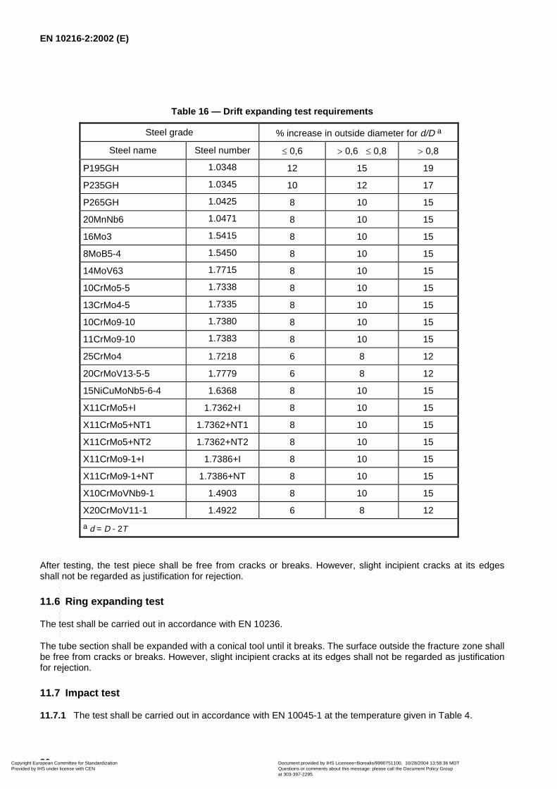
11.5 Drift expanding test
The test shall be carried out in accordance with EN 10234.
The tube section shall be expanded with a 60° conical tool until the percentage increase in outside diametershown in Table 16 is reached.
Copyright European Committee for Standardization Provided by IHS under license with CEN
Document provided by IHS Licensee=Borealis/9990751100, 10/28/2004 13:58:36 MDTQuestions or comments about this message: please call the Document Policy Groupat 303-397-2295.
--`,```,`,,`,``,`,```,`,,`,,-`-`,,`,,`,`,,`---
EN 10216-2:2002 (E)
30
Table 16 — Drift expanding test requirements
Steel grade % increase in outside diameter for d/D a
Steel name Steel number � 0,6 � 0,6 � 0,8 � 0,8
P195GH 1.0348 12 15 19
P235GH 1.0345 10 12 17
P265GH 1.0425 8 10 15
20MnNb6 1.0471 8 10 15
16Mo3 1.5415 8 10 15
8MoB5-4 1.5450 8 10 15
14MoV63 1.7715 8 10 15
10CrMo5-5 1.7338 8 10 15
13CrMo4-5 1.7335 8 10 15
10CrMo9-10 1.7380 8 10 15
11CrMo9-10 1.7383 8 10 15
25CrMo4 1.7218 6 8 12
20CrMoV13-5-5 1.7779 6 8 12
15NiCuMoNb5-6-4 1.6368 8 10 15
X11CrMo5+I 1.7362+I 8 10 15
X11CrMo5+NT1 1.7362+NT1 8 10 15
X11CrMo5+NT2 1.7362+NT2 8 10 15
X11CrMo9-1+I 1.7386+I 8 10 15
X11CrMo9-1+NT 1.7386+NT 8 10 15
X10CrMoVNb9-1 1.4903 8 10 15
X20CrMoV11-1 1.4922 6 8 12
a d = D - 2T
After testing, the test piece shall be free from cracks or breaks. However, slight incipient cracks at its edgesshall not be regarded as justification for rejection.
11.6 Ring expanding test
The test shall be carried out in accordance with EN 10236.
The tube section shall be expanded with a conical tool until it breaks. The surface outside the fracture zone shallbe free from cracks or breaks. However, slight incipient cracks at its edges shall not be regarded as justificationfor rejection.
11.7 Impact test
11.7.1 The test shall be carried out in accordance with EN 10045-1 at the temperature given in Table 4.
Copyright European Committee for Standardization Provided by IHS under license with CEN
Document provided by IHS Licensee=Borealis/9990751100, 10/28/2004 13:58:36 MDTQuestions or comments about this message: please call the Document Policy Groupat 303-397-2295.
--`,```,`,,`,``,`,```,`,,`,,-`-`,,`,,`,`,,`---

EN 10216-2:2002 (E)
31
11.7.2 The mean value of the three test pieces shall meet the requirements given in Table 4. One individualvalue may be below the specified value, provided that it is not less than 70 % of that value.
11.7.3 If the width (W) of the test piece is less than 10 mm, the measured impact energy (KVp) shall beconverted to the calculated impact energy(KVc) using the following equation:
W
KVKV
pc
10 � (7)
where:
� KVc is the calculated impact energy, in J;
� KVp is the measured impact energy, in J;
� W is the width of the test piece, in mm.
The calculated impact energy KVc shall conform to the requirements given in 11.7.2.
11.7.4 If the requirements of 11.7.2 are not met, then an additional set of three test pieces may be taken at thediscretion of the manufacturer from the same sample and tested. To consider the test unit as conforming, aftertesting the second set, the following conditions shall be satisfied simultaneously:
the average value of the six tests shall be equal to or greater than the specified minimum average value;
not more than two of the six individual values may be lower than the specified minimum average value;
not more than one of the six individual values may be lower than 70 % of the specified minimum average value.
11.7.5 The dimensions in millimetres of the test pieces, the measured impact energy values and the resultingaverage value shall be reported.
11.8 Leak tightness test
11.8.1 Hydrostatic test
The hydrostatic test shall be carried out at a test pressure of 70 bar 2) or at a test pressure P calculated usingthe following equation, whichever is lower:
D
TSP
� 20 (8)
where :
� P is the test pressure, in bar;
� D is the specified outside diameter, in mm;
� T is the specified wall thickness, in mm;
� S is the stress, in MPa, corresponding to 70 % of the specified minimum yield strength (see Table 4) for thesteel grade concerned.
The test pressure shall be held for not less than 5 s for tubes with an outside diameter D less than or equal to457 mm and for not less than 10 s for tubes with an outside diameter D greater than 457 mm.
The tube shall withstand the test without showing leakage or visible deformation.
2) 1 bar = 100 kPa
Copyright European Committee for Standardization Provided by IHS under license with CEN
Document provided by IHS Licensee=Borealis/9990751100, 10/28/2004 13:58:36 MDTQuestions or comments about this message: please call the Document Policy Groupat 303-397-2295.
--`,```,`,,`,``,`,```,`,,`,,-`-`,,`,,`,`,,`---

EN 10216-2:2002 (E)
32
NOTE This hydrostatic leak-tightness test is not a strength test.
Option 14: A test pressure different from that specified in 11.8.1 and corresponding to stresses below 90% ofthe specified minimum yield strength (see Table 4) for the steel grade concerned is specified.
11.8.2 Electromagnetic test
The test shall be carried out in accordance with EN 10246-1.
11.9 Dimensional inspection
Specified dimensions, including straightness, shall be verified.
The outside diameter shall be measured at tube ends. For tubes with outside diameter D � 406,4 mm, thediameter may be measured using a circumference tape.
Unless option 15 is specified the wall thickness shall be measured at both tube ends.
Option 15 : The wall thickness shall be measured away from the tube ends in accordance withan agreedprocedure.
11.10 Visual examination
Tubes shall be visually examined to ensure conformity to the requirements of 8.4.1.
11.11 Non-destructive testing
11.11.1 Tubes of test category 2 shall be subjected to a Non-Destructive Testing for the detection oflongitudinal imperfections, in accordance with EN 10246-7, to acceptance level U2, sub-category C or EN10246-5 acceptance level F2.
Unless option 16 is specified, the selection of the test method is at the discretion of the manufacturer.
Option 16: The test method is specified by the purchaser.
Regions at the tube ends not automatically tested shall either be subjected to manual/semi-automatic ultrasonictesting in accordance with EN 10246-7 to acceptance level U2, sub-category C or be cropped off.
11.11.2 If option 8 is specified (see 8.4.2.2), the tubes shall be subjected to ultrasonic testing for the detectionof transverse imperfections in accordance with EN 10246-6 to acceptance level U2, sub-category C.
11.11.3 If option 9 is specified (see 8.4.2.2), the tubes shall be subjected to ultrasonic testing for the detectionof the laminar imperfections in accordance with EN 10246-14 to acceptance level U2.
11.11.4 For tubes ordered by minimum wall thickness Tmin (see option 11), the acceptance level shall apply tothe calculated wall thickness Tc as determined in accordance with the formula stated in clause 8.1.
11.12 Material identification
Each tube made from alloy steel (see 5.1) shall be tested by an appropriate method to ensure that the correctgrade is being supplied.
11.13 Retests, sorting and reprocessing
For retest, sorting and reprocessing the requirements of EN 10021 shall apply.
Copyright European Committee for Standardization Provided by IHS under license with CEN
Document provided by IHS Licensee=Borealis/9990751100, 10/28/2004 13:58:36 MDTQuestions or comments about this message: please call the Document Policy Groupat 303-397-2295.
--`,```,`,,`,``,`,```,`,,`,,-`-`,,`,,`,`,,`---

EN 10216-2:2002 (E)
33
12 MARKING
12.1 Marking to be applied
The marking shall be indelibly marked on each tube at least at one end. For tubes with outside diameter D � 51mm the marking on tubes may be replaced by the marking on a label attached to the bundle or box.
The marking shall include the following information:
� the manufacturer's name or trade mark ;
� the number of this European standard and the steel name (see 5.2);
� the test category in case of non-alloy steel grades;
� the cast number or a code number;
� the mark of the inspection representative;
� an identification number (e.g. order or item number) which permits the correlation of the product or deliveryunit to the related document.
Example of marking:X - EN 10216-2 - P265GH - TC1 - Y- Z1 - Z2
where:
� X is the manufacturer's mark;
� TC1 is the designation of the test category 1;
� Y is the cast number or a code number;
� Z1 is the mark of the inspection representative;
� Z2 is the identification number.
12.2 Additional marking
Option 17: Additional marking, as agreed upon at the time of enquiry and order, shall be applied.
13 PROTECTION
The tubes shall be delivered without a temporary protective coating.
Option 18: A temporary protective coating or durable coating and/or lining shall be applied.
Copyright European Committee for Standardization Provided by IHS under license with CEN
Document provided by IHS Licensee=Borealis/9990751100, 10/28/2004 13:58:36 MDTQuestions or comments about this message: please call the Document Policy Groupat 303-397-2295.
--`,```,`,,`,``,`,```,`,,`,,-`-`,,`,,`,`,,`---

EN 10216-2:2002 (E)
34
Annex A
(Informative)
Creep rupture strength values
The creep rupture strength values of steel grades covered by this Part of EN 10216 are given in Table A1.
Table 17 Creep rupture strength valuesSteel grade Temperature Creep rupture strength values for (MPa ) a b c d
Steel name Steel number °C 10 000 h 100 000 h 200 000 h 250 000 hP235GHP265GH
400410420430440450460470480490500
182166151138125112100
88776758
141128114100
88776656473932
128115102
8977665646302624
122109
97867464544433----
20MnNb6 400410420430440450460470480490500
243221200180161143126110
968474
179157136117100
857363554741
157*135*115*
97*82*70*60*52*44*37*
--
150*128*108*
91*77*66*56*48*41*32*
--16Mo3 450
460470480490500510520530540550
298273247221196171148125104
8464
236205176149124102
8365514032
218188158129105
846753423425
210179148122
9878635038----
14MoV6-3 450460470480490500510520530540550560570580590600
377349324298274249225203181162143126112
978574
305276249224200177155135117102
877565584841
282255226202179158136117101
86746354474034
275247220195171150129110
9582705950433732
Copyright European Committee for Standardization Provided by IHS under license with CEN
Document provided by IHS Licensee=Borealis/9990751100, 10/28/2004 13:58:36 MDTQuestions or comments about this message: please call the Document Policy Groupat 303-397-2295.
--`,```,`,,`,``,`,```,`,,`,,-`-`,,`,,`,`,,`---

EN 10216-2:2002 (E)
35
Table A 1 (continued)Steel grade Temperature Creep rupture strength values for (MPa ) a b c d
Steel name Steel number °C 10 000 h 100 000 h 200 000 h 250 000 h10CrMo5-513CrMo4-5
450460470480490500510520530540550560570580590600
377347319292264238209181155131109
9074605041
290258227198170145121100
8065534438312620
264233203175148123102
82665141353025----
257225193164138114
927358463731--------
10CrMo9-10 450460470480490500510520530540550560570580590600
308284261238216195176158142126111
9988786960
229212194177160141124105
9581706153464035
204188172156140124108
948068574943383328
196180165150143118103
887664544640343026
11CrMo9-10 400410420430440450460470480490500510520
382355333312294276259242225208191174157
313269272255238221204187170153137122107
Copyright European Committee for Standardization Provided by IHS under license with CEN
Document provided by IHS Licensee=Borealis/9990751100, 10/28/2004 13:58:36 MDTQuestions or comments about this message: please call the Document Policy Groupat 303-397-2295.
--`,```,`,,`,``,`,```,`,,`,,-`-`,,`,,`,`,,`---

EN 10216-2:2002 (E)
36
Table A 1 (continued)
Steel grade Temperature Creep rupture strength values for (MPa ) a b c d
Steel name Steel number °C 10 000 h 100 000 h 200 000 h 250 000 h20CrMoV13-5-5 420
430440450460470480490500510520530540550
470440410360310270240210186169152134117
98
420370310260220190165145127114101
877459
15NiCuMoNb5-6-4
400410420430440450460470480490500
402385368348328304274242212179147
373349325300273245210175139104
69X11CrMo5+I 450
460470480490500510520530540550560570580590600610620630
196180166152140128116105
9585776963585045413733
147133119108
98897969625549443834302624----
130118107
96867667585246413631272422------
126114102
9081726355494338342925----------
X11CrMo5+NT1X11CrMo5+NT2
450460470480490500510520530540550560570580590600
----
242215188164145128113100
887869605346
270225188157131113
9682706050----------
237202170141116
968068584840----------
226189159131108
907564544537
---------
Copyright European Committee for Standardization Provided by IHS under license with CEN
Document provided by IHS Licensee=Borealis/9990751100, 10/28/2004 13:58:36 MDTQuestions or comments about this message: please call the Document Policy Groupat 303-397-2295.
--`,```,`,,`,``,`,```,`,,`,,-`-`,,`,,`,`,,`---
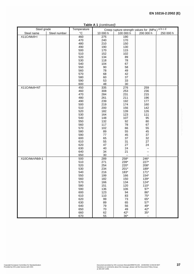
EN 10216-2:2002 (E)
37
Table A 1 (continued)Steel grade Temperature Creep rupture strength values for (MPa ) a b c d
Steel name Steel number °C 10 000 h 100 000 h 200 000 h 250 000 hX11CrMo9+I 460
470480490500510520530540550560570580590600
275240210190170152134118104
907868605348
190170150130115102
897867584942373330
X11CrMo9+NT 450460470480490500510520530540550560570580590600610620630640650
335308284261239219200182164148132117102
8977655547403430
276253231211192174156139123107
92786655453731272421--
259236215196177160142126111
958067554537322724------
X10CrMoVNb9-1 500510520530540550560570580590600610620630640650660670
289271254234216199182166151136123110
998979706255
258*239*220*201*183*166150134120106
948373655649
42*36*
246*227*208*189*171*154*139*124*110*
97*86*75*65*57*49*42*35*
--
Copyright European Committee for Standardization Provided by IHS under license with CEN
Document provided by IHS Licensee=Borealis/9990751100, 10/28/2004 13:58:36 MDTQuestions or comments about this message: please call the Document Policy Groupat 303-397-2295.
--`,```,`,,`,``,`,```,`,,`,,-`-`,,`,,`,`,,`---

EN 10216-2:2002 (E)
38
Table A 1 (continued)
Steel grade Temperature Creep rupture strength values for (MPa ) a b c d
Steel name Steel number °C 10 000 h 100 000 h 200 000 h 250 000 hX20CrMoV11-1 480
490500510520530540550560570580590600610620630640650
348319292269247225205184165147130113
978472615244
289263236212188167147128111
958169595143363126
270242218194170149129112
9681685849423630----
a The values listed in the Table are values suggested by ECCC (1) and are average values from scatter range determinedfrom existing data which will be assessed from time to time after test results are available and corrected if necessary.The values for the steel grades 14MoV6-3 and X10CrMoVNb9-1 have been obtained by new evaluation. For theremaining steel grades the values were obtained from creep rupture strength values given in national and internationalstandards
b The creep rupture strength values given up to the elevated temperature listed in the Table, do not mean that the steelscan be used in continuous duty up to the these temperatures. A governing factor is the total stress during operation.
c For the creep rupture strength values indicated in the Table the extrapolation times are always less than a factor ofthree unless indicated by an asterisk (*).
d 1 MPa = 1 N/mm2
Copyright European Committee for Standardization Provided by IHS under license with CEN
Document provided by IHS Licensee=Borealis/9990751100, 10/28/2004 13:58:36 MDTQuestions or comments about this message: please call the Document Policy Groupat 303-397-2295.
--`,```,`,,`,``,`,```,`,,`,,-`-`,,`,,`,`,,`---

EN 10216-2:2002 (E)
39
Annex ZA (informative)
CLAUSES OF THIS EUROPEAN STANDARD ADDRESSING ESSENTIAL REQUIREMENTS OR OTHERPROVISIONS OF EU DIRECTIVES
This European Standard has been prepared under a mandate given to CEN by the European Commission andthe European Free Trade Association and supports essential requirements of EU Directive 97/23/EC.
Warning: Other requirements and other EU Directives may be applicable to the product(s) falling within thescope of this European Standard.
The clauses of this European Standard are likely to support the essential requirements of section 4 of annex 1,“Essential safety requirements” of the Pressure Equipment Directive 97/23/EC.
Compliance with this European Standard provides one means of conforming with the specific essentialrequirements of the Directive concerned.
Copyright European Committee for Standardization Provided by IHS under license with CEN
Document provided by IHS Licensee=Borealis/9990751100, 10/28/2004 13:58:36 MDTQuestions or comments about this message: please call the Document Policy Groupat 303-397-2295.
--`,```,`,,`,``,`,```,`,,`,,-`-`,,`,,`,`,,`---

EN 10216-2:2002 (E)
40
Bibliography
EN 473, Non destructive testing - Qualification and certification of NDT personnel - General principles
(1) Results of investigations of the European Creep Collaborative Committee (ECCC, WG 3.2), Submitted toECISS/TC 29 by fax of 1998-04-03 ( Document ECISS/TC 29/SC 1 N. 245).
Copyright European Committee for Standardization Provided by IHS under license with CEN
Document provided by IHS Licensee=Borealis/9990751100, 10/28/2004 13:58:36 MDTQuestions or comments about this message: please call the Document Policy Groupat 303-397-2295.
--`,```,`,,`,``,`,```,`,,`,,-`-`,,`,,`,`,,`---

blankCopyright European Committee for Standardization Provided by IHS under license with CEN
Document provided by IHS Licensee=Borealis/9990751100, 10/28/2004 13:58:36 MDTQuestions or comments about this message: please call the Document Policy Groupat 303-397-2295.
--`,```,`,,`,``,`,```,`,,`,,-`-`,,`,,`,`,,`---

BS EN 10216-2:2002
BSI
389 Chiswick High Road
London
W4 4AL
BSI — British Standards InstitutionBSI is the independent national body responsible for preparing British Standards. It presents the UK view on standards in Europe and at the international level. It is incorporated by Royal Charter.
Revisions
British Standards are updated by amendment or revision. Users of British Standards should make sure that they possess the latest amendments or editions.
It is the constant aim of BSI to improve the quality of our products and services. We would be grateful if anyone finding an inaccuracy or ambiguity while using this British Standard would inform the Secretary of the technical committee responsible, the identity of which can be found on the inside front cover. Tel: +44 (0)20 8996 9000. Fax: +44 (0)20 8996 7400.
BSI offers members an individual updating service called PLUS which ensures that subscribers automatically receive the latest editions of standards.
Buying standards
Orders for all BSI, international and foreign standards publications should be addressed to Customer Services. Tel: +44 (0)20 8996 9001. Fax: +44 (0)20 8996 7001. Email: [email protected]. Standards are also available from the BSI website at http://www.bsi-global.com.
In response to orders for international standards, it is BSI policy to supply the BSI implementation of those that have been published as British Standards, unless otherwise requested.
Information on standards
BSI provides a wide range of information on national, European and international standards through its Library and its Technical Help to Exporters Service. Various BSI electronic information services are also available which give details on all its products and services. Contact the Information Centre. Tel: +44 (0)20 8996 7111. Fax: +44 (0)20 8996 7048. Email: [email protected].
Subscribing members of BSI are kept up to date with standards developments and receive substantial discounts on the purchase price of standards. For details of these and other benefits contact Membership Administration. Tel: +44 (0)20 8996 7002. Fax: +44 (0)20 8996 7001. Email: [email protected].
Information regarding online access to British Standards via British Standards Online can be found at http://www.bsi-global.com/bsonline.
Further information about BSI is available on the BSI website at http://www.bsi-global.com.
Copyright
Copyright subsists in all BSI publications. BSI also holds the copyright, in the UK, of the publications of the international standardization bodies. Except as permitted under the Copyright, Designs and Patents Act 1988 no extract may be reproduced, stored in a retrieval system or transmitted in any form or by any means – electronic, photocopying, recording or otherwise – without prior written permission from BSI.
This does not preclude the free use, in the course of implementing the standard, of necessary details such as symbols, and size, type or grade designations. If these details are to be used for any other purpose than implementation then the prior written permission of BSI must be obtained.
Details and advice can be obtained from the Copyright & Licensing Manager. Tel: +44 (0)20 8996 7070. Fax: +44 (0)20 8996 7553. Email: [email protected].
Copyright European Committee for Standardization Provided by IHS under license with CEN
Document provided by IHS Licensee=Borealis/9990751100, 10/28/2004 13:58:36 MDTQuestions or comments about this message: please call the Document Policy Groupat 303-397-2295.
--`,```,`,,`,``,`,```,`,,`,,-`-`,,`,,`,`,,`---