Embed Size (px)
Citation preview

Seanet SCU v5
0581-SOM-00002, Issue: 03 1 © Tritech International Ltd.
Seanet SCU v5
Product Manual
0581-SOM-00002, Issue: 03

Seanet SCU v5
0581-SOM-00002, Issue: 03 2 © Tritech International Ltd.
© Tritech International Ltd
The copyright in this document is the property of Tritech International Ltd. The document is supplied by Tritech International Ltd on theunderstanding that it may not be copied, used, or disclosed to others except as authorised in writing by Tritech International Ltd.
Tritech International Ltd reserves the right to change, modify and update designs and specifications as part of their ongoing product developmentprogramme.
All product names are trademarks of their respective companies.

Seanet SCU v5
0581-SOM-00002, Issue: 03 3 © Tritech International Ltd.
Table of ContentsHelp & Support ........................................................................................................ 4Warning Symbols ..................................................................................................... 51. Introduction .......................................................................................................... 62. Specification ........................................................................................................ 7
2.1. Dimensions ............................................................................................... 72.2. Computer and Electrical ........................................................................... 82.3. Physical ..................................................................................................... 82.4. SCUv5 Front Panel ................................................................................... 82.5. Seanet SCU (v5) Rear Panel Layout ........................................................ 92.6. Major differences between SCUv4 and SCUv5 ..................................... 10
3. System Options .................................................................................................. 114. Installation .......................................................................................................... 12
4.1. Connections ............................................................................................. 124.2. Communication Configuration ............................................................... 13
5. Operation ............................................................................................................ 156. System Software Configuration ........................................................................ 17
6.1. Seanet System Re-Installation ................................................................ 176.2. Repair of Seanet Pro .............................................................................. 176.3. Full Disk Re-Installation using Boot Recovery ...................................... 18
7. Maintenance ....................................................................................................... 20A. Data and Control Ports ..................................................................................... 21B. SCUv5 Communications Setup ........................................................................ 27C. ARCNET Termination ...................................................................................... 33D. Setting the computer IP address in Windows 7 ............................................... 34Glossary .................................................................................................................. 36

Seanet SCU v5
0581-SOM-00002, Issue: 03 4 © Tritech International Ltd.
Help & SupportFirst please read this manual thoroughly (particularly the Troubleshooting section,if present). If a warranty is applicable, further details can be found in a WarrantyStatement at the end of the manual.
Tritech International Ltd can be contacted as follows:
Mail Tritech International LtdPeregrine RoadWesthill Business ParkWesthill, AberdeenshireAB32 6JL, UK
Telephone ++44(0)1224 744 111
Fax ++44(0)1224 741 771
Email [email protected]
Website www.tritech.co.uk
Prior to contacting Tritech International Ltd please ensure that the following isavailable:
1. The Serial Numbers of the product and any Tritech International Ltd equipmentconnected directly or indirectly to it.
2. Software or firmware revision numbers.
3. A clear fault description.
4. Details of any remedial action implemented.
Contamination
If the product has been used in a contaminated or hazardous environmentyou must de-contaminate the product and report any hazards prior toreturning the unit for repair. Under no circumstances should a product bereturned that is contaminated with radioactive material.
The name of the organisation which purchased the system is held on record atTritech International Ltd and details of new software or hardware packages will beannounced at regular intervals. This manual may not detail every aspect of operationand for the latest revision of the manual please refer to www.tritech.co.uk
Tritech International Ltd can only undertake to provide software support of systemsloaded with the software in accordance with the instructions given in this manual. Itis the customer's responsibility to ensure the compatibility of any other package theychoose to use.

Seanet SCU v5
0581-SOM-00002, Issue: 03 5 © Tritech International Ltd.
Warning SymbolsThroughout this manual the following symbols may be used where applicable todenote any particular hazards or areas which should be given special attention:
Note
This symbol highlights anything which would be of particular interest tothe reader or provides extra information outside of the current topic.
Important
When this is shown there is potential to cause harm to the devicedue to static discharge. The components should not be handled withoutappropriate protection to prevent such a discharge occurring.
Caution
This highlights areas where extra care is needed to ensure that certaindelicate components are not damaged.
Warning
DANGER OF INJURY TO SELF OR OTHERS
Where this symbol is present there is a serious risk of injury or loss of life.Care should be taken to follow the instructions correctly and also conducta separate Risk Assessment prior to commencing work.

Seanet SCU v5
0581-SOM-00002, Issue: 03 6 © Tritech International Ltd.
1. IntroductionThe Seanet Surface Control Unit SCU (v5) incorporates the very latest in electronicsand PC technology including readers for memory cards and a built-in factory restoremode. The latest v5 model of the SCU has again been designed with reliabilityand robustness in mind. The SCU is housed in a rugged 3U rack mount chassisand incorporates a front panel Remote Access Terminal (RAT) which enables allfunctions to be controlled by a combination of pointer and function button operations.
The Seanet SCU (v5) is designed to control and display the complete range of TritechInternational Ltd sonars and subsidiary subsea sensors,
Features:
• The SCU can simultaneously run combinations of (amongst others) Imaging Sonar,Profiling Sonar, Bathymetric & Oceanographic package and Sidescan together.
• Uses a fast ARCNET communications to the subsea devices allowing a standarddata rate of 156kbps (max cable length 1200m) with options for fibre-opticinterfaces and other Baud rates available for longer cable lengths.
• Simultaneous connection and operation of Gemini heads via Ethernet.
• Able to run on SVGA/SXGA monitors at up to 1280 x 1024 screen resolution andon latest QXGA capable monitors at up to 2048 x 1536 screen resolution.
• Built-in factory restore disk, for simple diskless restoration to original settings, alsocontains a minimum of 32GB SSD (10GB reserved for Operating System)
• Compact Flash or SD slot in front panel.
• As well as sonar data, other data including NMEA 1083, Pipetracker, TurnsCounter and Compass data may be recorded.
• A range of interface ports is provided including DA-15 ARCNET, USB2.0, DE-9serial, Ethernet RJ45, PS/2, SVGA/SXGA & Video Out, Parallel Centronics andAudio.
• All data collected by the subsea devices can be made available on one or moreserial ports - 5 x DE-9 COM ports built in for this purpose and four of these ports(A – D) are general purpose and can provide RS232, RS485, RS422 and ARCNETconnections.
• Rack-mountable in racks of depth 330mm or greater.
Note
A range of factory fit options are available on request, such asvideo capture cards, please contact Tritech International Ltd for moreinformation.

Seanet SCU v5
0581-SOM-00002, Issue: 03 7 © Tritech International Ltd.
2. Specification
2.1. Dimensions

Specification Seanet SCU v5
0581-SOM-00002, Issue: 03 8 © Tritech International Ltd.
2.2. Computer and Electrical
Processor Intel™ Dual Core (or better)Operating System Microsoft Windows™ EmbeddedPrimary Control PS/2 Remote Access Terminal (RAT)Video Output SVGA, XGA or SXGAARCNET Link 1 x 156kbit·s-1 (1500m) or 78kbit·s-1 (2500m)Storage Media Minimum 32GB SSD (10GB reserved for OS)Interface Ports 4 x 9-pin DE-9 ports (configurable RS-232, RS-485,
RS-422, ARCNET)1 x 15-pin DA-15 port for ARCNET or RS2321 x 24VDC at 36VA Output (for equipment test purposes)Front and rear USB 2.0 portsMulti-card reader (CF Type 1 & SD card)Ethernet
Input Voltage Universal 100-240VAC 50/60HzOptions Composite PAL/NTSC output
Composite video inputInternal HDD (instead of SSD)Additional Gigabit Ethernet ports (for Gemini sonars).
Note
Any connectors on the motherboard are not part of the SCU specificationand may be used as part of the normal operation of the unit but their useis not covered by this manual.
2.3. Physical
Weight ~10kgMaterial Aluminium, Stainless SteelOperating Temperature 5 to 35°CStorage Temperature -20 to 50°C
2.4. SCUv5 Front Panel1. The RAT can be de-coupled from the main unit completely or operated from an
RS232 extension cable. The function of the RAT controls depend on which subseasensors are fitted, and the user should refer to the appropriate section of eachproduct manual for full details.

Specification Seanet SCU v5
0581-SOM-00002, Issue: 03 9 © Tritech International Ltd.
2. The AUX Power Switch toggles the DC Voltage Output on the rear of the SCU.This DC voltage is accessible on the DC OUT banana plugs on the rear.
3. The memory card reader is compatible with Compact Flash I/II and SD cards. Therestore disk on earlier Seanet SCUs is no longer used as there is an in-built factoryrestore option for system recovery.
4. The port activity LEDs indicate the state and configuration of the DE-9 COM ports(A - D) accessible on the rear.
2.5. Seanet SCU (v5) Rear Panel Layout
1. Power supply with DC Out ports
2. Motherboard connectors
3. Expansion slots (showing default installed graphics card) also for optional itemssuch as video capture cards, additional Ethernet cards, etc.
4. (from left to right) Earth mounting point, DE-9 (top row) and DA-15 (bottom row)ports for RS232, RS422, RS485, ARCNET and RAT, system restore button
For detailed pin-out diagrams and wiring options for the DE-9 and DA-15connectors refer to Appendix A, Data and Control Ports and Appendix B, SCUv5Communications Setup.
The motherboard connectors are subject to change in line with Tritech InternationalLtd policy of continual product improvement, however, this will in not affect ordinaryoperation of the SCU. Generally the motherboard will have USB 2.0 ports, 1 or 2PS/2 keyboard/mouse ports and RJ45 Ethernet.
Caution
If a DE-9 port is present on the motherboard it will only work with RS232signals but is not fitted with over-current protection. To avoid potential
Specification Seanet SCU v5
0581-SOM-00002, Issue: 03 10 © Tritech International Ltd.
damage to the motherboard it is recommended that this port is not usedto connect sensor equipment.
2.6. Major differences between SCUv4 and SCUv5
Feature SCU (v4) SCU (v5)RAM 256Mb 512Mb (minimum)Data Storage Zip Drive, optional HDD SSD Drive, optional HDD
(instead of SSD)ARCNET Sonar Ports 1 x AIF card interface 2 x SCU5 Main Board
PortsSerial Sonar Ports 3 x RS232 4 x RS232/RS485 or 2 x
RS422USB Ports 2 front, 2 rear 4 front plus rear portsARCNET Ports PCI AIF, Node 255 V5 Main Board, Node 252Ethernet LAN Port Optional Normally 1, more can be
added.Port Activity LED Display No YesAux Power Supply 24V 1A, non-switchable 24V 2.4A switchable, 33V
1.8A option, LED onwarning
External Storage Floppy Disk Drive, ZIPDrive
Compact Flash Card, SDCard, Memory Stick
System Recovery Device ZIP Disk – stored internalto SCU. SCU Lid needs tobe removed to access
Internal flash memory –switched system restore.No internal accessrequired.
Caution
If a DE-9 port is present on the motherboard it will only work with RS232signals but is not fitted with over-current protection. To avoid potentialdamage to the motherboard it is recommended that this port is not usedto connect sensor equipment.

Seanet SCU v5
0581-SOM-00002, Issue: 03 11 © Tritech International Ltd.
3. System OptionsThe SCUv5 can be factory supplied or field retro-fitted with a number of add-onoptions to provide expanded functionality and added user control. New options maybe added at any time and may not be limited to the following available options.
Hard Disk Drive (HDD) The primary storage device may optionallybe specified to be a hard disk of at least40GB capacity. This can be partitioned intoa C: (system) and D: (user) drive in suitableproportion to reserve enough additional spaceon the D: drive for log file storage. Thisdrive would be installed instead of the 32GB(minimum) SSD.
Video Input A video input card may optionally bespecified, to receive composite PAL/NTSCvideo, at up to 25 frames per second.
MicronNav System Support A connector port may be optionally specifiedfor the MicronNav navigation system. Thisenables an Ultra-Short Baseline (USBL)transducer to be connected to the SCU, fordisplay of sub-sea vehicle bearing and rangeinformation via Seanet software. A subseavehicle used in such an application willrequire a Tritech Micron Modem transponder.
33V Auxiliary Power Supply The 24V Auxiliary power supply may beoptionally replaced by a 33V supply, for usewhere an instrument is to be supplied over along cable length for example.
Additional Ethernet ports For controlling multiple Gemini sonar headsadditional Ethernet ports can be provided. It ispossible to install cards with one, two or fourextra ports per card.

Seanet SCU v5
0581-SOM-00002, Issue: 03 12 © Tritech International Ltd.
4. InstallationThe Seanet SCU (v5) should be carefully removed from its transit case and checkedto see that the control unit is undamaged. The unit may be inverted to check for anyparts that may have been loosened during transit. If so, remove the unit cover andinvestigate further. The unit should be firmly mounted in a clean dry installation suchas a rack system.
If fitted in a confined space such as a rack, then an adequate supply of cool air shouldbe available to keep the unit from overheating. The front and back of the unit musthave a clear space for air venting, cooling and cable access. If the unit is mountedon a desk or bench, then it should be secured against movement when powered on.Again leave space for air circulation and cable access.
The SCU is supplied with the screen display and output and communications alreadyconfigured. The user should not have to change the screen display layout or comm’sset-up unless it is not suited to their use (contact Tritech International Ltd for moredetails).
4.1. Connections
Caution
The power should be turned off before making a connection between thesonar head and surface controller (SCU or SeaHub).
The SCU mains inlet should be connected to a fused (rated 5A) 100-240V 50/60Hzpower supply. The mains supply to the SCU must be clean, free of transient noisespikes and interference, as suitable for computers and electrical instruments. If themains supply is of a dirty nature then a suitable filter or uninterruptible power supply(UPS) must be fitted. There is an On/Off isolator switch at the rear of the unit andmomentary soft power switch at the front. The isolator switch must be ON beforeoperating the front momentary soft power switch.
For the full connection details of the SCUv5 please refer to Appendix B, SCUv5Communications Setup.
Connect the DVI port to a suitable digital display, or use the DVI to VGA adapter ifconnecting a VGA computer screen. If the RAT is used remotely, use the extensionlead supplied to connect it to either the front of the Seanet SCU, or on the rear portmarked RAT. As an alternative to using the RAT a keyboard and mouse can beconnected to the motherboard PS/2 ports. Finally connect any sensor equipment tothe serial ports, ARCNET or Ethernet port.

Installation Seanet SCU v5
0581-SOM-00002, Issue: 03 13 © Tritech International Ltd.
Caution
COM1 does not have any ESD / Transient protection and so should not beused for connection of serial Sensors and devices. Ports A – D are installedwith protection.
Before powering up the Seanet SCU check that the subsea heads are correctlyconnected, check the data communication lines for shorts to other wires, and checkthe termination resistance is correct at both ends.
4.2. Communication Configuration
Fitted inside the SCU, located at the front panel, is the SCUv5 Main Board. Thisis a multi-purpose board that houses the bulk of the circuitry from the supersededAIF PCB. This includes the ARCNET interface, for communications with the subseasensor heads, and the RAT interface. The Main Board is also populated with theMemory Card Reader, Port Status LEDs and hardware for COM Ports A to D. TheSCUv5 Main Board will appear in the Setup table as Node 252 which replaces theNode 255 for the superseded AIF Card.
Full details of all the connections are contained in Appendix B, SCUv5Communications Setup. Normal communications with the subsea devices is via acustomised version of the ARCNET network system and requires a good qualitybalanced twisted pair cable.
An optional RS232 interface can be provided to allow telemetry connection througha fibre optic system capable of 115kbit·s-1 transmission. The RS232 interface isavailable in the guise of an RS232 to ARCNET converter PCB that is installed in adry pod inside the ROV. Alternatively, an intelligent 4000m pressure rated JunctionBox will provide the RS232 interface to the network of SeaKing ARCNET devices.
Note
The SeaKing range of Subsea Sensors are designed to work from asmoothed DC power supply of 18-36V DC (Absolute Maximum 36VDC).
If using a rectified transformer PSU, the output of the PSU must have a filter capacitorof not less than 470μF, for each head being powered. If an unregulated PSU is used,then make sure that the voltage value measured at the head is in the range 18-36v DC,both in power off and running conditions. If powering the head(s) down a long leador umbilical, the maximum recommended loop resistance of the power line must notexceed 10ohm for one head, 5ohm for two heads, and 3ohm for three heads. If thesupplied voltage is less than 18V DC the head may not operate correctly.

Installation Seanet SCU v5
0581-SOM-00002, Issue: 03 14 © Tritech International Ltd.
Caution
Never try to make Tritech International Ltd sonar heads work down along cable by increasing the PSU output voltage above the recommendedvoltage.
For detail of the appropriate termination requirements for a Tritech International LtdARCNET network please refer to Appendix C, ARCNET Termination
Use with Ethernet Sonars
The motherboard Ethernet port is capable of driving a single Ethernet device, such asa Gemini imaging sonar or profiler, or it can be coupled to a network switch to enablemultiple sonars to be operated. A specially designed Gemini Hub unit is availablefrom Tritech International Ltd which enables multiple Gemini profilers and othersensors to be attached through the Ethernet port.
Extra software may be required to operate the Ethernet sonars, please contact TritechInternational Ltd for more details.
Use with Serial Devices
The SCU is installed with four DE-9 ports on the rear panel for use with serialcommunications. These ports can be configured for different standards and for surveydata output ports to a data logger or as ports where Tritech International Ltd or other3rd party sensors/devices can be connected.
Ports A to D can be configured to operate to different communication standards:
Port RS232 RS422 RS485 ARCNETA YES NO YES NOB YES YES YES NOC YES NO YES YESD YES NO YES YES
Caution
The internal motherboard DE-9 connector (if present) is not fitted withESD protection and so should not be used to connect sonar or sensorequipment. Doing so might damage the motherboard of the SCU.
For a more complete listing of the ports and their capabilities (as well as pin-outdiagrams) please refer to Appendix A, Data and Control Ports

Seanet SCU v5
0581-SOM-00002, Issue: 03 15 © Tritech International Ltd.
5. OperationOnce a system has been installed in conjunction with the relevant sections of thismanual and any relevant sensor manuals, it can be tested in air by powering up thesystem and observing that communications with the subsea device(s) is established.
Caution
The power should be turned off before making a connection between thesonar head and surface controller (SCU or SeaHub).
When the SCU and subsea heads are switched on, the system display will appearon the monitor after a few seconds delay. Until the SCU, Remote Access Terminal(RAT), and Subsea elements are communicating correctly, the Status Bar willdisplay a Timeout (‘Timeout Node xx’) message for each Node that it is trying tocommunicate with. These messages will be removed from the display as each subseadevice is detected as operating correctly.
If the RAT or subsea elements are not powered up, not present, or have a faultsomewhere, then error messages will be shown in the status bar boxes on the bottomof the display. If error messages appear, check that all the system parts are connectedand that all leads/cables are correctly installed.
The following sections of this manual will describe the general software controls inaddition to installation and connection instructions. Further, separate manual sectionswill describe operation of each of the subsea Sensors and their connection details.
Full details of the Seanet Pro and Seanet Setup operation can be found in the SeanetPro Software Manual. There are also a number of devices that can be connected to theSeanet SCU including Imaging Sonar, Profiler, Bathymetric and Sidescan. Refer tothe individual device manual for specific details of their screen controls and functions.
Note
The four DE-9 ports are labelled as ScuA to ScuD in Seanet Setup.These are assigned virtual port numbering in Windows. Two otherports will be shown, ScuMain and ScuAux - these are used forcommunication inside the SCU and not for external devices.
The port numbering will be re-set if a system restore is performed and due to themanner in which Windows manages resources the ports may be numbered differentlyeach time the system is restored. If desired they can be manually re-assigned fromthe Windows™ Control Panel.
Setting COM Ports
1. From within the Control Panel select System & Security.
2. Select the System button.

Operation Seanet SCU v5
0581-SOM-00002, Issue: 03 16 © Tritech International Ltd.
3. Click on Device Manager in the left-hand pane.
4. Under Ports (COM & LPT) select the port to be changed and right click onit and select Properties.
5. Navigate to the Port Settings tab and then click the Advanced button andfrom here it is possible to change the port number to one that had not yet beenassigned.

Seanet SCU v5
0581-SOM-00002, Issue: 03 17 © Tritech International Ltd.
6. System Software ConfigurationYour system will be delivered with Microsoft Windows™ Embedded and SeanetSystem Software pre-installed.
A complete image of the Microsoft Windows™ Embedded Operating System isprovided on an internal flash memory device. This is independent from the primaryC:\ partition where the system software is installed to. This image can be re-installedat any time through a boot recovery process to restore the primary C:\ partition to afactory default state.
The boot recovery process is initiated via a switch on the rear panel of the SCU. Fileson the C:\ partition are re-installed during the recovery process, leaving user files onthe D:\ drive unaffected.
There are 2 levels of restoration that can be carried out:
1. Re-installation of the Seanet Pro software only to factory default. It isrecommended where possible that this is attempted before level 2 in order torecover the SCU.
2. Complete re-installation of the primary C:\ partition to factory supplied condition.Use of this level will erase all files currently stored on the C:\ drive and replacewith a factory installation state. D:\ drive user files will be unaffected. The D:\drive is also where a copy of the Seanet Pro software installer and manuals canbe located.
6.1. Seanet System Re-InstallationThe Seanet SCU has the following drive letters:
Drive C:\ Primary, flash memory boot drive where system files and Seanet Prosoftware are installed. This drive should NOT be used for storing anylog files.
Drive D:\ This drive is where the Seanet Pro software installer and operatormanuals can be found. There is space to use this drive for user filesand log files. The ‘My Documents’ folder has also been moved tothis drive.
6.2. Repair of Seanet ProIf the Seanet SCUv5 is booting up normally and only the Seanet Pro software is givinga problem then, as a first level recovery, the Seanet Pro software can be re-installedfrom the D:\ drive.

System Software Configuration Seanet SCU v5
0581-SOM-00002, Issue: 03 18 © Tritech International Ltd.
Before re-installing Seanet Pro, it is advisable to first remove the existing SeanetPro installation. This can be performed through Control Panel – Programsand Features. Select the Seanet Pro entry and then follow the on-screeninstructions to remove the program.
For re-installation browse to the D:\SeaNet Installer folder and runSCU5Setup.exe and follow the installation prompts throughout. After installationis complete, click on the Finish button which will reboot the SCU ready to runSeanet Pro on Microsoft Windows™ re-start.
6.3. Full Disk Re-Installation using Boot RecoveryIf any part of the Microsoft Windows™ operating system becomes corrupt andrequires re-installing, the original factory configuration can be restored from a backupimage of the primary disk that is retained on internal flash memory. Refer to thefollowing steps for guidance:
1. With keyboard connected and SCU powered down, power on the SCU andimmediately press and release the System Restore button located on the rearof the SCU.
2. When the BIOS POST message is displayed after power up, press the <F8>or <F12> button on the keyboard (note: this button can very depending on themotherboard fitted - if in doubt watch the screen during boot-up and select theappropriate button to get to the "boot" menu). This will start the SCU with theboot selection screen.
3. On this screen will be listed the boot device options which will vary dependingon the SCU version between PRETEC 01GB USB DOF (early SCUv5 units),USB Disk module PMAP (later Microsoft Windows™ XP SCUv5 units) orUSB-HDD (for Microsoft Windows™ 7 SCUv5 units). Select the correct deviceand press <Enter> on the keyboard.
4. The Microsoft Windows™ Startup Menu will soon appear.
• For Microsoft Windows™ XP units the user should select Option 1 RestoreSystem Disk to Factory Defaults, press <Enter> on the keyboardand then press the <Y> key to confirm disk restore.
• For Microsoft Windows™ 7 units the option is labelled as "A" and RestoreHard Disk to Factory Defaults, so button <A> should be pressedand then the <Enter> key.
5. The system retore will start and when it is complete a notification to press thereset button on the front of SCU appears. At this point, press the Reset button toreboot the SCU.
6. ( Microsoft Windows™ XP only) On reboot, notification will be displayed that themachine is resealed, click the OK button at this point to reboot the SCU once more.

System Software Configuration Seanet SCU v5
0581-SOM-00002, Issue: 03 19 © Tritech International Ltd.
7. ( Microsoft Windows™ XP only) Once rebooted, Microsoft Windows™ willrestart and a ‘Log On to Windows’ box will appear. Click OK to proceed past this.
8. A prompt will then appear to install Seanet Pro. Click on OK to proceed with thisand follow the instructions given during the installation process.
9. Once Seanet Pro installation is complete, click Finish which will restart theSCU for a final time. The restore operation is now complete.
Note
If this device is not listed then you will need to reboot once more followingthe above steps – it is important that the System Restore button is pressedimmediately after power on as this engages the flash memory where thebackup image is held.

Seanet SCU v5
0581-SOM-00002, Issue: 03 20 © Tritech International Ltd.
7. MaintenanceThere are few user-serviceable parts inside the Seanet SCU (v5) that can be checkedand/or replaced.
Firstly, it is recommended that the unit be used in a clean, well ventilated and dust-free environment. Also, operating in extreme temperature and humidity should beavoided if possible. The environmental temperature should be between 5 to 35°C.
ESD / Transient Protection (COM Port A - D )
Note
The onboard motherboard COM1 is not fitted with any isolation or surgeprotection and so should only be used as a data logger output port andNOT used for Sensor interfacing.
The multi-purpose Ports A - D are installed with electrical surge protection. Theseelements are fitted on the SCU V5 Main Board which is located inside the SCUat the front. If the COM Ports A through D are subjected to very high electrostaticnoise or transients, the protective elements on this PCB would blow / open-circuitand therefore protect the serial UART that is installed on the main board.
If in the unlikely event the protection does blow on the PCB then the user has anumber of options open to themselves:
1. Replace the SCUv5 Main Board PCB with a spare if carried. Contact Tritech ora local agent who will supply this PCB.
2. Replace the blown protective elements / components on the PCB. This wouldobviously require some diagnosing and know-how on the part of the user.
3. Mark or label the failed port as inoperative and continue to use the remainingavailable Ports until such time as the faulty Port can be repaired.
Front Air Inlet FilterIt is recommended that this filter be replaced annually although a replacement maybe required sooner if operating the unit in a particularly dirty environment.
Note
The Tritech Part number of the air filter is 5023.
Seanet SCU v5
0581-SOM-00002, Issue: 03 21 © Tritech International Ltd.
Appendix A. Data and Control Ports
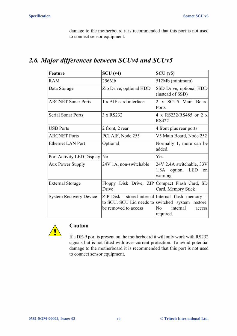
Waterblock Pin-out Diagram
Tritech Waterblock
Pin MAIN port AUX port Cable colour
1RS232 TX
ARCNET ARS485 A
RS232 RXARCNET A
RS485 AYellow
2RS232 RX
ARCNET BRS485 B
RS232 TXARCNET B
RS485 BBlue
3 +DC Power Red4 -DC Power Black5 RS232 Ground Green6 Earth/cable shield cable screen
On the SCU a range of interface ports is provided, arranged as follows:
Location Port Type Number providedUSB 2.0 4Front PanelRAT Interface 1Sonar/Sensor/Serial Interface 4RAT Interface 1ARCNET Link 2SVGA, XGA, SXGA 2
Rear Panel
TV/Video out (optional) 1
Notes:
1. 500mA current capacity per USB port
2. Sonar/Sensor Serial ports are software selectable up to 4 x RS-232, up to 4 xRS-485, 2 x ARCNET, 1 x RS-422.
3. The ARCNET Link provides a long distance communications link to other TritechInternational Ltd instruments. It is software configurable (using Seanet) to operateup to 1500m cable (156kbps) or 2500m (78kbs).
4. The SVGA, XGA, SXGA port is a 15w High Density D, analogue; DVI (DigitalVideo Interface)
5. TV/Video out is Composite PAL/NTSC.
6. Motherboard ports are subject to change and are not part of this specification.

Data and Control Ports Seanet SCU v5
0581-SOM-00002, Issue: 03 22 © Tritech International Ltd.
Comms Status and Data Activity LEDs (Ports A – D)The layout of the Communication Port COMMS status and data activity LED’s isshown below.
The COMMS row of LEDs are bi-colour, with Red - Receive; Green - Transmit
The remaining LEDs are Blue, indicating the communications protocol which hasbeen software selected for a particular port.
If working in reduced lighting conditions, the overall brightness of the statusindicators may be controlled through the “Seanet Setup” configuration interface forthe SCU.
Port A DetailsAll signals are fully isolated and voltage transient protected with respect to thecommunications power supply. The modes are software selectable. When used inRS-232 mode, the pin out of this port is wired in the same way as a PC serial “COM”port (i.e. using DTE signal directions), and compatible with any standard RS-232peripherals and cabling.
Supports data transfer rates of up to 921,600 baud.
PORT A
SCU DE-9 male connector
Pin RS232 RS4851 ‡ ‡2 RX TX/RX.A3 TX TX/RX.B4 ‡ ‡5 GROUND GROUND6 ‡ ‡7 RTS ‡8 CTS ‡9 ‡ ‡‡ = connected for handshaking only.

Data and Control Ports Seanet SCU v5
0581-SOM-00002, Issue: 03 23 © Tritech International Ltd.
Note
Port A will also work as a 3-wire RS232 connection without RTS andCTS. Pin 7 and 8 maintain signal levels of +/-12V for both 3-wire RS232and RS485
Port B DetailsAll signals are fully isolated and voltage transient protected with respect to thecommunications power supply.
When used in RS-232 mode, the pin out of this port is wired in the same way as aPC serial “COM” port (i.e. using DTE signal directions), and compatible with anystandard RS-232 peripherals and cabling.
Supports data transfer rates of up to 921,600 baud in RS-232/RS-485 mode.
PORT B
SCU DE-9 male connector
Pin RS232 RS422 RS4851 ‡ ‡ ‡2 RX TX.A TX/RX.A3 TX TX.B TX/RX.B4 ‡ ‡ ‡5 GROUND GROUND GROUND6 ‡ ‡ ‡7 ‡ RX.B ‡8 ‡ RX.A ‡9 ‡ ‡ ‡‡ = connected for handshaking only.
• 150ohm termination resistor is fitted across pins 2 and 3, when in RS-485/RS-422mode, and pins 7 and 8 permanently.
• Pins 7 and 8 will have RS-422 signal levels (+/-5V) present on them whenconfigured in RS-232 or RS-485 mode.
• RTS and CTS handshaking protocol is not available on this port. PC Serial portsshould be configured to use no handshaking.
Port C & D DetailsSignals are fully isolated and voltage transient protected with respect to thecommunications power supply.

Data and Control Ports Seanet SCU v5
0581-SOM-00002, Issue: 03 24 © Tritech International Ltd.
Supports data transfer rates of up to 921,600 baud in RS-232/RS-485 mode.
PORT C/D
SCU DE-9 male connector
Pin RS232 RS485 ARCNET1 ‡ ‡ ‡2 RX RX/TX.A LAN A3 TX RX/TX.B LAN B4 ‡ ‡ ‡5 GROUND GROUND GROUND6 ‡ ‡ ‡7 ‡ ‡ ‡8 ‡ ‡ ‡9 ‡ ‡ ‡‡ = connected for handshaking only.
• 150ohm termination resistor is fitted across pins 1 and 2, when in RS-485 mode.
• RTS and CTS handshaking protocol not available on this port. PC Serial portsshould be configured to use no handshaking.
ARCNET Port
DA-15 female connector, providing access to:
• Isolated +12V and +5V supplies.
• Isolated and protected TTL ARCNET connections (LAN PULSE1, LAN PULSE2,LAN EN and LAN RX).
• Isolated and protected differential ARCNET connections (LAN A, LAN B).
• Optional connections to “Port A” serial interface signals – consult factory fordetails.

Data and Control Ports Seanet SCU v5
0581-SOM-00002, Issue: 03 25 © Tritech International Ltd.
ARCNET
SCU DA-15 female connector
Pin Connection Pin Connection1 nc 9 +12v DC
2 COMMSGround 10 VCC
3 Ground 11 LAN EN4 LAN RX 12 RS232 RTX5 RS232 CTS 13 RS232 RX6 RS232 TX 14 LAN PULSE17 LAN PULSE2 15 LAN B8 LAN A
nc = not connected
• Signals on pins 4, 5, 6, 7, 8, 11, 12, 13, 14 and 15 are with respect to the groundon pin 2.
• The +12V output on pin 9, and the +5V output on pin 10 is with respect to pin 3,External Ground.
• The RS-232 signals on pins 5, 6, 12, 2 and 13 are present simultaneously on thisconnector and the DE-9 connector PORT A.
RAT InterfaceA single 9-Way D-Type Female connector for connection to a V2 RAT (with PS2mouse and RS-485 data signals only)
RAT
SCU DE-9 female connector
Pin Function1 GROUND2 +5v DC3 RAT RS485 B4 RAT RS485 A5 ‡6 ‡7 PS/2 SCLK8 PS/2 SDATA9 +12v DC‡ = connected for handshaking only.
• RAT RS-485 and PS2 data signals are not isolated, and are with respect to theinternal power supplies “+5V” and “GROUND”.

Data and Control Ports Seanet SCU v5
0581-SOM-00002, Issue: 03 26 © Tritech International Ltd.
• An internal 150ohm termination resistor is fitted across the RS-485 input signals(pins 3 and 4).

Seanet SCU v5
0581-SOM-00002, Issue: 03 27 © Tritech International Ltd.
Appendix B. SCUv5 Communications SetupThere is no AIF card inside the V5 Seanet SCU, in its place is the V5 Main Board.The Main Board provides 4 Serial Ports A,B,C,D which can be configured to RS232,RS485 or RS422. These are available on separate 9 pin D-type connectors
In addition to this the Main Board feeds a 15 pin D-type connector which has thesame pinouts as the 15D connector fitted to the AIF card on earlier SCU models.Serial Port A is also available from 15D on the same pins as the earlier model SCUSerial LAN (AUX 0) connection.
The 4 Non-ARCNET serial ports can have several functions depending on userconfiguration.
• To allow single node communication to Subsea sensors such as Split AIF card,Multicomm or single head RS232 direct connection.
• REMV4 operations
• They can be used as a standard com port for interface to 3rd party devices suchas GPS or compass.
The Main Board is detected as NODE 252 in the Seanet Setup program with TYPEset to SCU as below
Note
The flexibility of the V5 Seanet SCU means that not all connectionpossibilities are listed in this document, but an set of examples are shown.
SeaKing Sensor(S) in ARCNET through Twisted Pair
The traditional method of transmitting Tritech data from Subsea to Surface is via atwisted pair cable.
SCUv5 Communications Setup Seanet SCU v5
0581-SOM-00002, Issue: 03 28 © Tritech International Ltd.
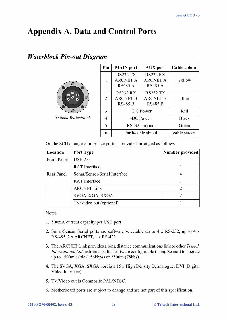
Connection to the V5 SCU should be made through the DA-15 connector, wired asbelow with any additionally networked heads connected in series off the first head.
Tritech 6-pin connector
SCU DA-15 female connector
Pin TritechConnector
DA-15Connector
1 ARCNET A nc2 ARCNET B nc3 (see note) nc4 (see note) nc5 nc nc6 nc nc7 - nc8 - ARCNET A9 - nc10 - nc11 - nc12 - nc13 - nc14 - nc15 - ARCNET B
nc = not connected
Note
Power will need to be supplied to the sonar head through pin 3 (forexample 24V DC supply for a SeaKing) and pin 4 (0V ground) of theTritech connector - the ARCNET port will not be able to supply this powerand a suitable external source should be used.
SeaKing Sensor(s) in ARCNET through Fiber Optic Interface
It is possible to connect a standard ARCNET system through Fiber, allowing multipleheads without the need for a stand alone AIF card or Junction Box
SCUv5 Communications Setup Seanet SCU v5
0581-SOM-00002, Issue: 03 29 © Tritech International Ltd.
The connection to the SCU should be made through the ARCNET (DA-15) port andwired in the same manner as the ARCNET Through Twisted Pair shown above.
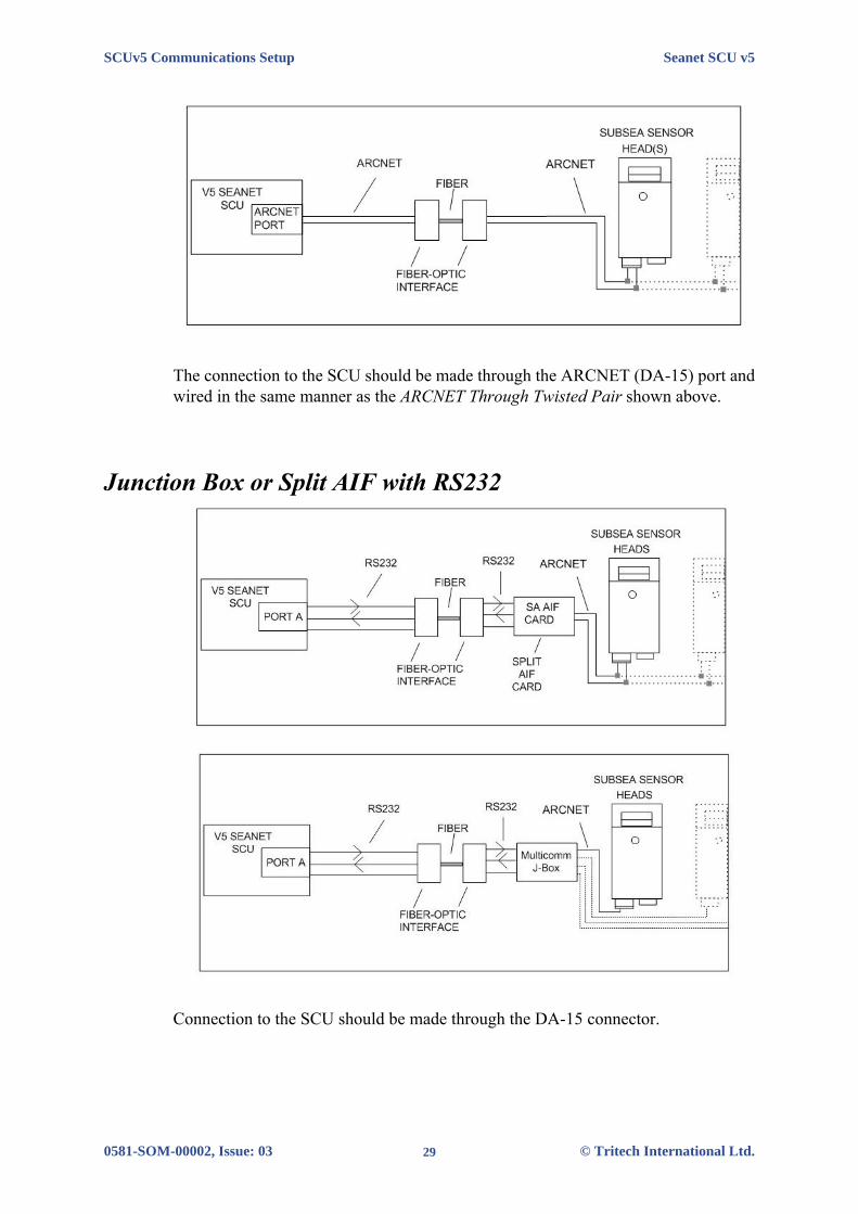
Junction Box or Split AIF with RS232
Connection to the SCU should be made through the DA-15 connector.

SCUv5 Communications Setup Seanet SCU v5
0581-SOM-00002, Issue: 03 30 © Tritech International Ltd.
ARCNET
SCU DA-15 female connector
Pin Connection Pin Connection1 nc 9 nc2 Ground 10 nc3 nc 11 nc4 nc 12 nc5 nc 13 RS232 Rx6 RS232 Tx 14 nc7 nc 15 nc8 nc
nc = not connected
Note
In DA-15 can operate in RS232 mode (this type of operation is fixedduring manufacture of the unit and cannot subsequently be changed). InRS232 mode the output has the same internal connection as the DE-9RS232 PORT A and therefore a connection can be used to PORT Ainstead. For a pin-out of of PORT A see Appendix A, Data and ControlPorts.
Single SeaKing Sensor in RS232
The V5 SCU can support direct connection of a single node to a dedicated RS232 port.
Connection can be made through the DA-15 connector (if it is wired for RS232communications) or through one of the standard DE-9 ports, such as PORT A shownabove. This configuration is single head so subsea networking is not possible.

SCUv5 Communications Setup Seanet SCU v5
0581-SOM-00002, Issue: 03 31 © Tritech International Ltd.
Multiple Sensors Connected to the SCU
The connection of multiple serial sensors to a single V5 SCU is possible. Each sensormust feed into the SCU on its own port:
Connection should be made through the DE-9 connectors A through D, each wiredfor serial communications as shown in Appendix A, Data and Control Ports (thechosen serial standard, RS232, RS422 or RS485 will depend on the sensor in use -note that only port B can use RS422.
SeaKing Sensors Through TTL to ARCNET Modem
This is only applicable to systems operating with the Tritech International Ltd TTLto ARCNET interface PCB or alternative such as the Subsea 7 “Eagle Eye” PCB.

SCUv5 Communications Setup Seanet SCU v5
0581-SOM-00002, Issue: 03 32 © Tritech International Ltd.
Connection to the SCU should be made through the DA-15 connector, wired as below.TTL signals are isolated on the V5 Seanet SCU.
ARCNET
SCU DA-15 female connector
Pin Connection Pin Connection1 nc 9 nc2 Ground 10 nc3 nc 11 nc4 LAN.Rx 12 nc5 nc 13 nc6 nc 14 LAN.Tx7 nc 15 nc8 nc
nc = not connected

Seanet SCU v5
0581-SOM-00002, Issue: 03 33 © Tritech International Ltd.
Appendix C. ARCNET TerminationDepending on the cable length the ARCNET communication link requires atermination resistor to be installed at each end of the umbilical cable. Normally thisis supplied fitted within the ARCNET cable DA-15 or within the SCU/SeaHub at thesurface and is left for the user to fit at the sub-sea end in a convenient junction boxor by use of a special waterblock.
Caution
Fitting the resistor inside the subsea device is not recommended and mayinvalidate the warranty.
The purpose of these terminations is to attenuate any electrical interference or"reflections" which may occur due to an impedance mis-match and the overall aimis to improve signal quality and negate any effects which might otherwise be felt byother sources of impedance such as from the cable itself.
The diagram below shows best practice to use when installing termination resistorson an ARCNET network of Tritech International Ltd sonar products.
Note
A special yellow waterblock is available from Tritech International Ltdwhich contains an in-line impedance of 39Ω which will enable quick andeasy installation of the subsea termination resistor.
Cable length Termination Baud rate settingLess than 100m Single 39Ω subsea resistor Normal baud rate100-1200m 270Ω at surface and 39Ω subsea Normal baud rate1200-2500m 270Ω at surface and 39Ω subsea Half baud rate
Note
If there is more than one sensor connected then the sub-sea resistor shouldbe fitted at the junction box or splice of the cable.

Seanet SCU v5
0581-SOM-00002, Issue: 03 34 © Tritech International Ltd.
Appendix D. Setting the computer IP address inWindows 7
The following instructions apply to a computer running Windows 7, though thesequence for other operating systems will be similar.
Disconnect the computer from any existing network.
First click on the Start Menu and select Control Panel.
Under Network and Internet click on View network status andtasks.
This will bring up the Network and Sharing Center which allowsconfiguration of any networks on the computer. Click on Change adaptersettings on the left-hand pane.

Setting the computer IP address in Windows 7 Seanet SCU v5
0581-SOM-00002, Issue: 03 35 © Tritech International Ltd.
A list of attached network devices should now present itself. Find the one which thesonar is to be connected to and double-click on it.
The Local Area Connection Properties dialog should be displayed. Findthe entry labelled Internet Protocol Version 4 (TCP/IPv4), select itand then click on the Properties button.
In the properties dialog which opens there will either be Obtain an IP addressautomatically or Use the following IP address selected. If an IPaddress is already present, make a note of it before changing any values since it will beneeded if the computer is ever restored to the previous network. Refer to appropriatesection of this manual for the correct IP addresses to use.

Seanet SCU v5
0581-SOM-00002, Issue: 03 36 © Tritech International Ltd.
GlossaryAIF ARCNET Interface - can refer to either the interface port on a
SeaHub or SCU or to the expansion card available for installationinto a computer.
ARCNET Attached Resource Computer NETwork - a network protocolsimilar to Ethernet but with the advantage of working over muchlonger ranges.
BIOS Basic Input Output System - the code that loads when a computeris initially turned on.
COM Short for "communications". When used in the context ofcomputers typically it refers to the Microsoft Windowsdesignation of a serial communications port (in this instance itmay be given a number, "COM3", for example). In the contextof sonar hardware it can be used to refer to the circuit board thatcontrols the communication to the surface.
DA-15 A 15 pin D shaped connector used mainly for the ARCNETconnection on the SCU and SeaHub.
DC Direct Current
DE-9 A 9 pin D shaped connector commonly used for serialcommunications on computers.
DVI Digital Visual Interface, a standard connector for connectingfrom a computer to a monitor.
Ethernet A family of computer networking technologies for local areanetworks (LANs).
Gemini Unless specified this can refer to any of the multibeam sonarsin the Gemini range by Tritech International Ltd such as theGemini Imager (720id), Narrow Beam Imager or Gemini Profiler(620pd).
Gemini Hub A rack mountable device capable of driving 2 Gemini sonars andmultiple serial sensors and outputting the data to a PC network.
LED Light Emitting Diode
MicronNav An Ultra Short Baseline (USBL) system for location andtracking of ROVs, divers, etc. Consists of the MicronNav 100surface control unit (similar to the SeaHub but with differentfunctionality) a "dunking transducer" which is mounted on thevessel/dockside under the waterline and a responder which ismounted on the ROV or Hammerhead tripod.

Glossary Seanet SCU v5
0581-SOM-00002, Issue: 03 37 © Tritech International Ltd.
NMEA National Marine Electronics Association - a USA basedstandards association responsible for overseeing electrical anddata communications standards between marine devices (dueto become the IMEA or International Marine ElectronicsAssociation in 2012).
NTSC National Television System Committee - an analogue televisionstandard used in most of North America.
PAL Phase Alternating Line - an analogue television colour encodingsystem.
PCB Printed Circuit Board
PSU Power Supply Unit
RAT Remote Access Terminal - the detachable front part of the TritechSurface Control Unit (SCU) computer. Provides an alternative tousing a keyboard and mouse.
RJ45 Registered Jack wiring scheme commonly used to refer tothe 8 position 8 contact (8P8C) connector wired for Ethernetcommunications.
RS232 Traditional name for a series of standards for serial binary datacontrol signals.
RS485 A standard for defining the electrical characteristics of driversand receivers for use in a balanced digital multipoint system (alsoknown as EIA-485).
RX Receive (data)
SCU Surface Control Unit - a specially manufactured computer whichis rack mountable and capable of processing the data fromthe sonar equipment running either Windows XP Embedded orWindows 7 and Seanet Pro or Gemini software.
SeaHub An alternative to using a Seanet SCU, this device connects to alaptop or PC via USB interface, essentially this takes the signalfrom the sonar (in RS232, RS485 or ARCNET) and converts itinto a signal suitable for the USB port of the computer.
Seanet Pro The software supplied by Tritech International Ltd which iscapable of running all the sonar devices.
TX Transmit (data)
USB Universal Serial Bus.