Embed Size (px)
Citation preview
SeaQuest with a Transversely Polarized Target (E1039)
M. Brooks, A. Klein (CoSpokesperson), D. Kleinjan, K. Liu, M. LiuM. McCumber , P. McGaughey , C. Da Silva
Los Alamos National Laboratory, Los Alamos, NM 87545
J. Arrington, D. Geesaman, M. Mesquita de Medeiros, P. Reimer, Z. YeArgonne National Laboratory, Argonne, IL 60439
C. Brown , D. ChristianFermi National Accelerator Laboratory, Batavia IL 60510
J.-C. PengUniversity of Illinois, Urbana, IL 61081
W.-C. Chang, Y.-C. ChenInstitute of Physics, Academia Sinica, Taiwan
S. SawadaKEK, Tsukuba, Ibaraki 305-0801, Japan
T.-H. ChangLing-Tung University, Taiwan
C. Aidala, W. Lorenzon, R. RaymondUniversity of Michigan, Ann Arbor, MI 48109-1040
T. Badman, E. Long, K. Slifer, R. ZielinskiUniversity of New Hampshire, Durham, NH 03824
R.-S. GuoNational Kaohsiung Normal University, Taiwan
Y. GotoRIKEN, Wako, Saitama 351-01, Japan
J.-P. ChenThomas Jefferson National Accelerator Facility, Newport News, VA 23606
K. Nakano, T.-A. ShibataTokyo Institute of Technology, Tokyo 152-8551, Japan
D. Crabb, D. Day, D. Keller (CoSpokesperson), O. RondonUniversity of Virginia, Charlottesville, VA 22904
G. Dodge, S. BueltmannOld Dominion University, Norfolk VA 23936
J. Dunne, D. Dutta, L. El Fassi,Mississippi State University, Starkville, MS 39762
E. KinneyUniversity of Colorado, Boulder, CO 80309
N. Doshita, T. Iwata, Y. MiyachiYamagata University, Yamagata 990-8560, Japan
M. Daugherity, D. Isenhower, R. Towell, S. WatsonAbilene Christian University, Abilene, TX 79601
1
Abstract
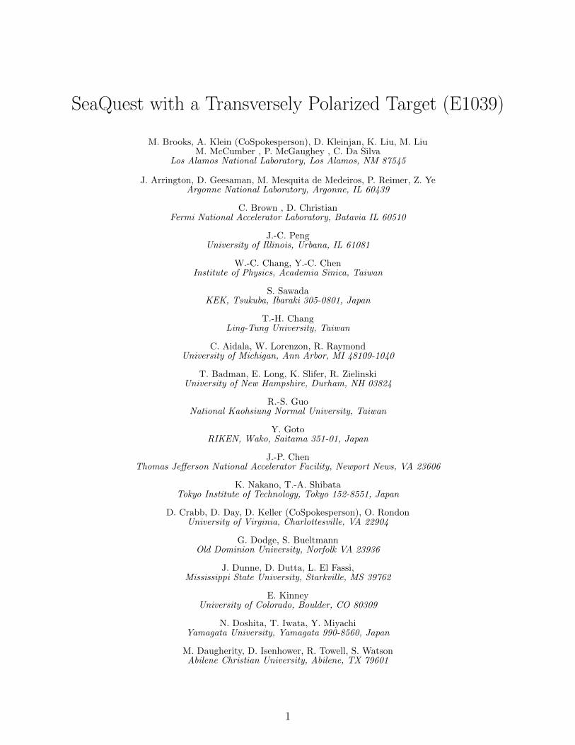
We have constructed a state-of-the-art, high luminosity polarized proton and deuterontarget and propose to measure the Sivers asymmetry for the u and d sea quarks in thenucleon for four different Bjorken xB bins in the range 0.1 < xB < 0.5, using the Drell-Yanprocess at SeaQuest. We will: i) perform the first measurement of the Sivers asymmetryin Drell-Yan scattering for sea quarks; ii) determine the flavor dependence of the Siversfunction for the u and d sea quarks iii) explore a unique range of virtualities and transversemomenta not accessible through Z0/W± measurements; and iv) determine the sign andpossibly the magnitude of the sea quark Sivers function in Drell-Yan for comparison to futuresea quark Sivers function determinations in Semi Inclusive Deep Inelastic Scattering (SIDIS).Measuring a nonzero Sivers asymmetry would provide “smoking gun” evidence for nonzeroorbital angular momentum of sea quarks; determination of the u and d Sivers function wouldallow comparison of the sea quark Sivers function flavor dependence to that for valence quarks;and measuring a sign change in the Sivers asymmetry between this measurement and futuremeasurements at the EIC would test a fundamental prediction of QCD.
This proposal seeks funding from DOE Office of Nuclear Physics for the installation of theE-1039 experiment, which could be the beginning of an exciting new spin physics program atFermilab that is complementary to the spin physics programs at RHIC and JLab.
2
Abstract
Contents
1 Introduction 5
2 Motivation 82.1 The Drell Yan Process . . . . . . . . . . . . . . . . . . . . . . . . . . . . . . . . . . 82.2 Theory . . . . . . . . . . . . . . . . . . . . . . . . . . . . . . . . . . . . . . . . . . . 9
2.2.1 TMDs . . . . . . . . . . . . . . . . . . . . . . . . . . . . . . . . . . . . . . . 112.2.2 Orbital Angular Momentum . . . . . . . . . . . . . . . . . . . . . . . . . . . 14
2.3 Current theoretical and experimental status . . . . . . . . . . . . . . . . . . . . . . 152.4 The angular dependence of the Drell-Yan cross section . . . . . . . . . . . . . . . . 162.5 The Measurements . . . . . . . . . . . . . . . . . . . . . . . . . . . . . . . . . . . . 18
2.5.1 p + p↑ . . . . . . . . . . . . . . . . . . . . . . . . . . . . . . . . . . . . . . . 182.5.2 p + d↑ . . . . . . . . . . . . . . . . . . . . . . . . . . . . . . . . . . . . . . . 18
3.2 The Polarized Target . . . . . . . . . . . . . . . . . . . . . . . . . . . . . . . . . . . 203.3 Beamline . . . . . . . . . . . . . . . . . . . . . . . . . . . . . . . . . . . . . . . . . . 213.5 Count Rates and Statistical Errors . . . . . . . . . . . . . . . . . . . . . . . . . . . 233.4 Integration of the polarized target into SeaQuest . . . . . . . . . . . . . . . . . . . . 233.6 Polarization Measurements . . . . . . . . . . . . . . . . . . . . . . . . . . . . . . . . 24
3.6.1 Proton Polarization Measurements . . . . . . . . . . . . . . . . . . . . . . . 243.6.2 Neutron Polarization Measurements . . . . . . . . . . . . . . . . . . . . . . . 253.6.3 Target Polarization Uncertainty . . . . . . . . . . . . . . . . . . . . . . . . . 263.6.4 Active Target Contributions . . . . . . . . . . . . . . . . . . . . . . . . . . . 27
3.7 Luminosity and Beam Intensity Uncertainty . . . . . . . . . . . . . . . . . . . . . . 273.7.1 Beam Profile . . . . . . . . . . . . . . . . . . . . . . . . . . . . . . . . . . . 273.7.2 Luminosity measurement . . . . . . . . . . . . . . . . . . . . . . . . . . . . 273.7.3 Consistency in Delivered Luminosity . . . . . . . . . . . . . . . . . . . . . . 28
3.8 Spectrometer Induced Uncertainities . . . . . . . . . . . . . . . . . . . . . . . . . . 293.9 Overall Systematic Error . . . . . . . . . . . . . . . . . . . . . . . . . . . . . . . . . 303.10 Expected Results . . . . . . . . . . . . . . . . . . . . . . . . . . . . . . . . . . . . . 30
4 Comparison to Competition 31
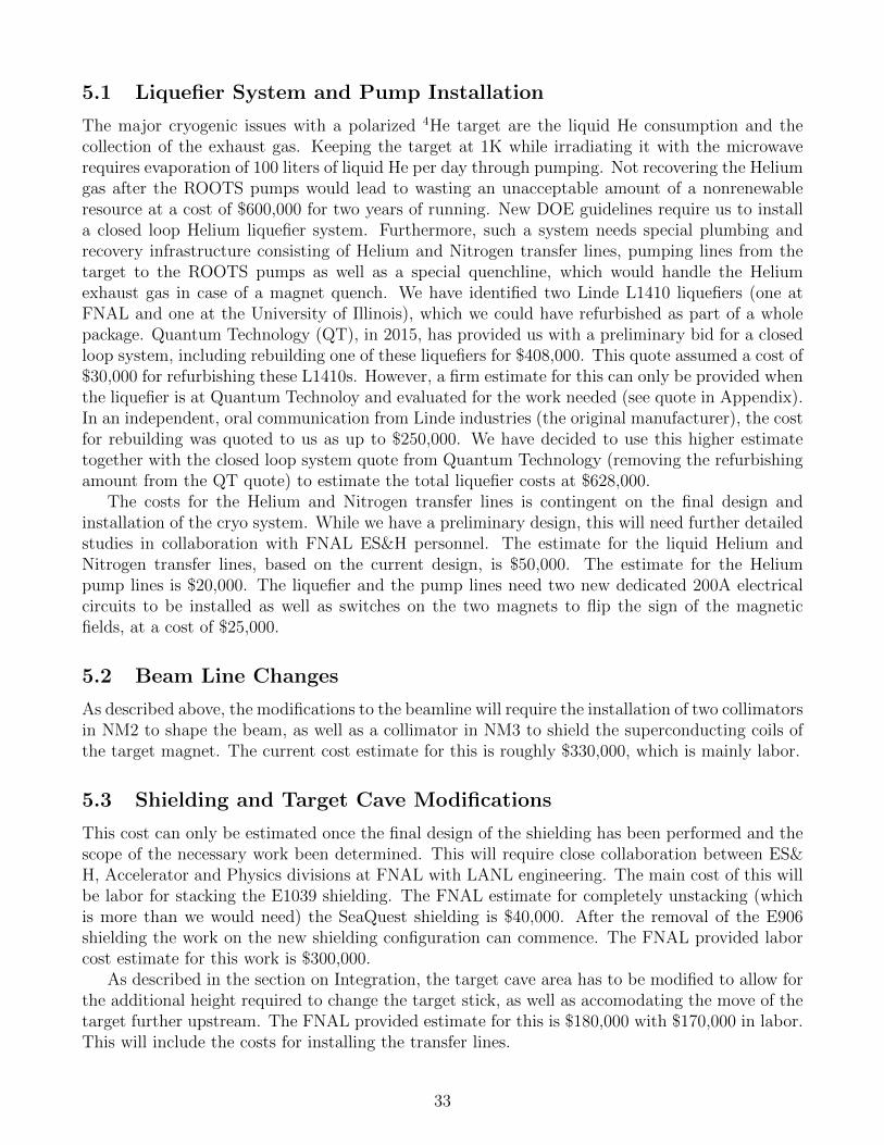
5 Budget Discussion 325.1 Liquefier System and Pump Installation . . . . . . . . . . . . . . . . . . . . . . . . 335.2 Beam Line Changes . . . . . . . . . . . . . . . . . . . . . . . . . . . . . . . . . . . . 335.3 Shielding and Target Cave Modifications . . . . . . . . . . . . . . . . . . . . . . . . 335.4 Total Installation Costs . . . . . . . . . . . . . . . . . . . . . . . . . . . . . . . . . . 34
Appendices 34
A Fermilab PAC 2013 and 2015 reviews 34
3
B The current accomplishments from the LDRD 35B.1 Experimental . . . . . . . . . . . . . . . . . . . . . . . . . . . . . . . . . . . . . . . 35B.2 Theoretical . . . . . . . . . . . . . . . . . . . . . . . . . . . . . . . . . . . . . . . . 37B.3 LANL reviews . . . . . . . . . . . . . . . . . . . . . . . . . . . . . . . . . . . . . . . 37
C Future Physics Opportunities 38C.1 Deuteron Tensor Function b1 . . . . . . . . . . . . . . . . . . . . . . . . . . . . . . . 38C.2 Explore gluon TMD/Twist-3 trigluon correlation functions and QCD dynamics with
heavy quarks . . . . . . . . . . . . . . . . . . . . . . . . . . . . . . . . . . . . . . . 39
D Letter of Intent P-1039 41
E Quote For Liquefier 48
4
1 Introduction
The central challenge of nuclear and particle spin physics is to disentangle exactly how the nucleon’sspin is built up from its quark and gluon constituents. It is well known that the proton is a spin-1/2particle, but how the constituents assemble into this quantized spin is still a mystery. Since thediscovery of the ”spin crisis” by the EMC collaboration [1], the global physics community, withthe support of the Department of Energy Office of Nuclear Physics has embarked on a multidecadeprogram to determine the individual contributions to the proton spin [2] [3]. Experiments haveestablished that the valence quark spins contribute around 30%, while the gluon intrinsic angularmomentum is still under active investigation at the Relativistic Heavy Ion Collider [4].
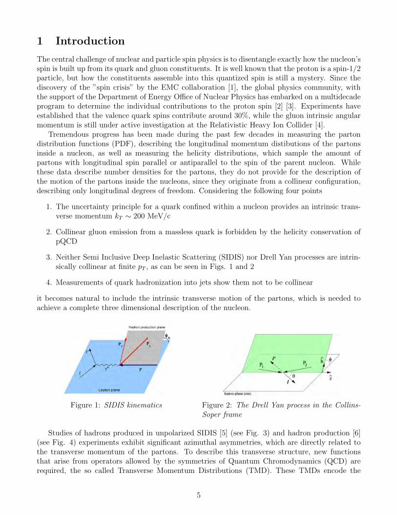
Tremendous progress has been made during the past few decades in measuring the partondistribution functions (PDF), describing the longitudinal momentum distibutions of the partonsinside a nucleon, as well as measuring the helicity distributions, which sample the amount ofpartons with longitudinal spin parallel or antiparallel to the spin of the parent nucleon. Whilethese data describe number densities for the partons, they do not provide for the description ofthe motion of the partons inside the nucleons, since they originate from a collinear configuration,describing only longitudinal degrees of freedom. Considering the following four points
1. The uncertainty principle for a quark confined within a nucleon provides an intrinsic trans-verse momentum kT ∼ 200 MeV/c
2. Collinear gluon emission from a massless quark is forbidden by the helicity conservation ofpQCD
3. Neither Semi Inclusive Deep Inelastic Scattering (SIDIS) nor Drell Yan processes are intrin-sically collinear at finite pT , as can be seen in Figs. 1 and 2
4. Measurements of quark hadronization into jets show them not to be collinear
it becomes natural to include the intrinsic transverse motion of the partons, which is needed toachieve a complete three dimensional description of the nucleon.
Figure 1: SIDIS kinematics Figure 2: The Drell Yan process in the Collins-Soper frame
Studies of hadrons produced in unpolarized SIDIS [5] (see Fig. 3) and hadron production [6](see Fig. 4) experiments exhibit significant azimuthal asymmetries, which are directly related tothe transverse momentum of the partons. To describe this transverse structure, new functionsthat arise from operators allowed by the symmetries of Quantum Chromodynamics (QCD) arerequired, the so called Transverse Momentum Distributions (TMD). These TMDs encode the
5
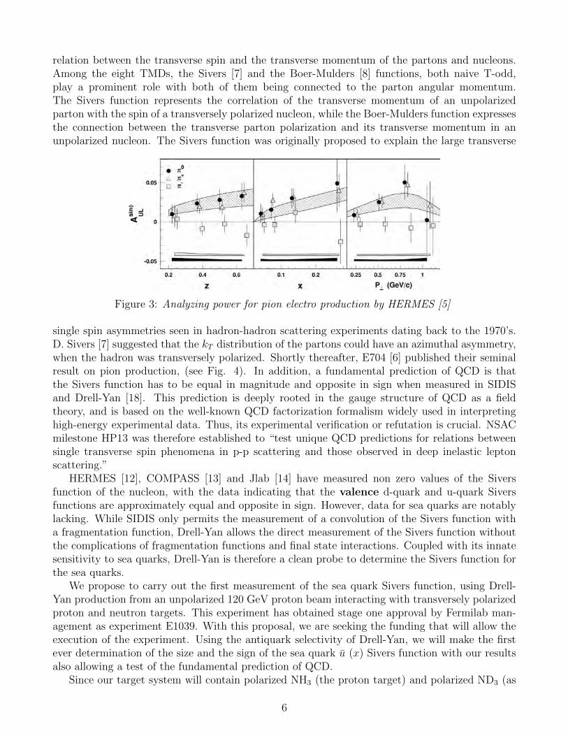
relation between the transverse spin and the transverse momentum of the partons and nucleons.Among the eight TMDs, the Sivers [7] and the Boer-Mulders [8] functions, both naive T-odd,play a prominent role with both of them being connected to the parton angular momentum.The Sivers function represents the correlation of the transverse momentum of an unpolarizedparton with the spin of a transversely polarized nucleon, while the Boer-Mulders function expressesthe connection between the transverse parton polarization and its transverse momentum in anunpolarized nucleon. The Sivers function was originally proposed to explain the large transverse
Figure 3: Analyzing power for pion electro production by HERMES [5]
single spin asymmetries seen in hadron-hadron scattering experiments dating back to the 1970’s.D. Sivers [7] suggested that the kT distribution of the partons could have an azimuthal asymmetry,when the hadron was transversely polarized. Shortly thereafter, E704 [6] published their seminalresult on pion production, (see Fig. 4). In addition, a fundamental prediction of QCD is thatthe Sivers function has to be equal in magnitude and opposite in sign when measured in SIDISand Drell-Yan [18]. This prediction is deeply rooted in the gauge structure of QCD as a fieldtheory, and is based on the well-known QCD factorization formalism widely used in interpretinghigh-energy experimental data. Thus, its experimental verification or refutation is crucial. NSACmilestone HP13 was therefore established to “test unique QCD predictions for relations betweensingle transverse spin phenomena in p-p scattering and those observed in deep inelastic leptonscattering.”
HERMES [12], COMPASS [13] and Jlab [14] have measured non zero values of the Siversfunction of the nucleon, with the data indicating that the valence d-quark and u-quark Siversfunctions are approximately equal and opposite in sign. However, data for sea quarks are notablylacking. While SIDIS only permits the measurement of a convolution of the Sivers function witha fragmentation function, Drell-Yan allows the direct measurement of the Sivers function withoutthe complications of fragmentation functions and final state interactions. Coupled with its innatesensitivity to sea quarks, Drell-Yan is therefore a clean probe to determine the Sivers function forthe sea quarks.
We propose to carry out the first measurement of the sea quark Sivers function, using Drell-Yan production from an unpolarized 120 GeV proton beam interacting with transversely polarizedproton and neutron targets. This experiment has obtained stage one approval by Fermilab man-agement as experiment E1039. With this proposal, we are seeking the funding that will allow theexecution of the experiment. Using the antiquark selectivity of Drell-Yan, we will make the firstever determination of the size and the sign of the sea quark u (x) Sivers function with our resultsalso allowing a test of the fundamental prediction of QCD.
Since our target system will contain polarized NH3 (the proton target) and polarized ND3 (as
6
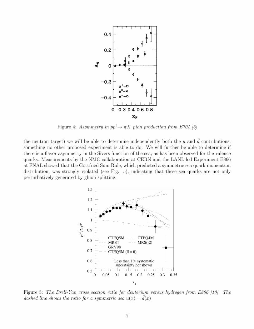
Figure 4: Asymmetry in pp↑→ πX pion production from E704 [6]
the neutron target) we will be able to determine independently both the u and d contributions;something no other proposed experiment is able to do. We will further be able to determine ifthere is a flavor asymmetry in the Sivers function of the sea, as has been observed for the valencequarks. Measurements by the NMC collaboration at CERN and the LANL-led Experiment E866at FNAL showed that the Gottfried Sum Rule, which predicted a symmetric sea quark momentumdistribution, was strongly violated (see Fig. 5), indicating that these sea quarks are not onlyperturbatively generated by gluon splitting.
0.5
0.6
0.7
0.8
0.9
1
1.1
1.2
1.3
0 0.05 0.1 0.15 0.2 0.25 0.3 0.35
x2
σpd
/2σ
pp
Less than 1% systematicuncertainty not shown
CTEQ5MMRSTGRV98
CTEQ4M
CTEQ5M (d_ = u
_)
MRS(r2)
Figure 5: The Drell-Yan cross section ratio for deuterium versus hydrogen from E866 [10]. Thedashed line shows the ratio for a symmetric sea u(x) = d(x)
7
The origin of this violation of perturbative QCD is still not understood and has led to thedevelopment of many different theoretical models. Among those, the pion cloud model of theproton, predicts a direct connection between the d excess seen in E866 (see Fig.5) and the orbitalangular momentum of the sea.
In summary, E1039 will measure the Sivers asymmetry for both the u and d quarks, withinthe range of 0.1 < xB < 0.5. Proton induced Drell-Yan production on polarized proton anddeuteron targets has never been performed. These measurements are complementary to the (stage-1) approved experiment E1027 at Fermilab [19], which will measure the Sivers function of thevalence quarks using a polarized proton beam on an unpolarized proton target. If the measuredsea quark Sivers function is non-zero, we will also determine its sign. While it is clear that theexistence of the Sivers function requires non-zero quark orbital angular momentum (OAM), thereis no model-independent connection between the Sivers distribution and the size of the quark OAMas of yet, so additional theoretical work is needed to provide a direct connection.
It is important to note that the proposed measurement is the only currently planned experimentwhich will cleanly access the sea quark Sivers function in a unique virtuality Q2 ∼ 10 GeV2 andtransverse momentum qT in the few GeV region. Current SIDIS measurements are dominated bythe valence quarks and are insensitive to sea quark contributions. The COMPASS experimentat CERN, using pion induced Drell-Yan, probes the valence region due to the antiquark contentof the beam. Measurements of single spin asymmetries in W±/Z0 production at RHIC probe acombination of the Sivers function and the parity-violating transverse helicity distribution g1T [9].The virtuality Q2 ∼ 10000 GeV2 and transverse momentum qT ∼ 10 GeV are also vastly different.Such large transverse momenta may also require a nonpertubative theoretical treatment.
While E1039 is a continuation of the SeaQuest experiment, there are some important changesand additions necessary to the current configuration. The installation of the polarized target willrequire not only some modifications to the beamline to protect the superconducting coils, butalso changes to the shielding around the target area and the first magnet. In addition, we willneed to purchase a closed loop liquid Helium system, to conform with new DOE requirementson nonrenewable resources. A detailed discussion of these changes can be found in Section 5. Inorder to cover these initial installation expenses we are asking for support from the DOE Office ofNuclear Physics.
2 Motivation
2.1 The Drell Yan Process
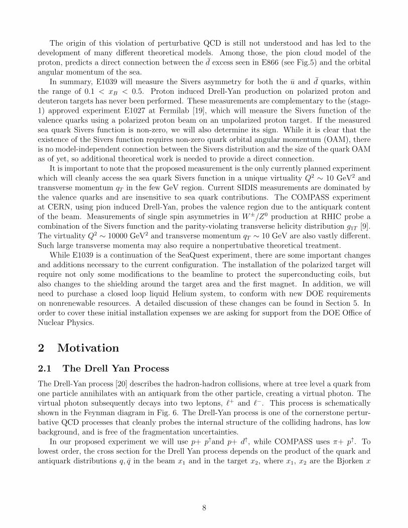
The Drell-Yan process [20] describes the hadron-hadron collisions, where at tree level a quark fromone particle annihilates with an antiquark from the other particle, creating a virtual photon. Thevirtual photon subsequently decays into two leptons, `+ and `−. This process is schematicallyshown in the Feynman diagram in Fig. 6. The Drell-Yan process is one of the cornerstone pertur-bative QCD processes that cleanly probes the internal structure of the colliding hadrons, has lowbackground, and is free of the fragmentation uncertainties.
In our proposed experiment we will use p+ p↑and p+ d↑, while COMPASS uses π+ p↑. Tolowest order, the cross section for the Drell Yan process depends on the product of the quark andantiquark distributions q, q in the beam x1 and in the target x2, where x1, x2 are the Bjorken x
8
µ+
µ-p (beam)
N (target)
x1 qx2 q
_γ*
Figure 6: The Drell-Yan process
and express the fraction of the longitudinal momentum of the nucleon carried by the quark.
dσ
dx1dx2
=4πα2
9sx1x2
∑i
e2i (q
Bi (x1, Q
2)qTi (x2, Q2) + qBi (x1, Q
2)qTi (x2, Q2) , (1)
s is the square of the center of mass energy and is given by s = 2mT ∗ EBeam + m2T + m2
B, withEBeam the beam energy and mB,T the rest masses of the beam and target nucleons. Measuringthe two decay leptons in the spectrometer allows one to determine the photon center of mass pγ‖(longitudinal) and pγT (transverse) momenta as well as the mass Mγ. From these quantities onecan deduce the momentum fractions of the quarks through:
xF =pγ‖
pγ,max‖= x1 − x2 , sx1x2 = M2
γ . (2)
If one chooses the kinematics of the experiment such that xF > 0 and x1 is large, the contributionsfrom the valence quarks in the beam dominate.
In this case, in Eq. 1 the second term becomes negligible and the cross section can be writtenas
dσ
dx1dx2
≈ 4πα2
9sx1x2
∑i
e2i qBi (x1, Q
2)qTi (x2, Q2) . (3)
For a proton beam on a proton target the process is dominated by the u(x1) distribution due to thecharge factor e2
i . To extract the d(x) Sivers asymmetry one has to measure the p+d↑ asymmetry.In the following discussion we will assume that the cross section on the deuteron is the sum of theproton and neutron cross sections and use isospin symmetry to equate dp and un and ignore strangeand heavier antiquarks in the target, as well as antiquarks in the beam. Through a simultaneousmeasurement of the pp↑ and pd↑ asymmetries one can independently extract the Sivers asymmetryfor both u and d.
2.2 Theory
The fundamental importance of studying transverse momentum dependent parton distributions(TMDs) and advancing the related theory of the nucleon spin is well summarized by the goals ofthe nuclear theory TMD Topical Collaboration, where LANL is a key member [21]. The study
9
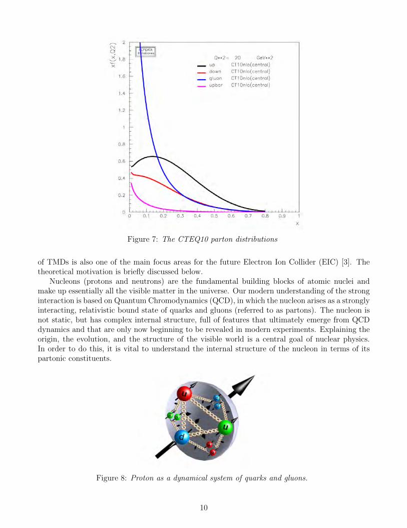
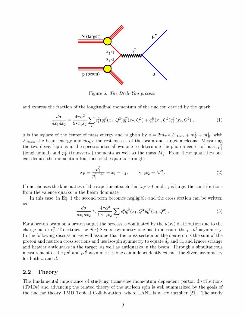
Figure 7: The CTEQ10 parton distributions
of TMDs is also one of the main focus areas for the future Electron Ion Collider (EIC) [3]. Thetheoretical motivation is briefly discussed below.
Nucleons (protons and neutrons) are the fundamental building blocks of atomic nuclei andmake up essentially all the visible matter in the universe. Our modern understanding of the stronginteraction is based on Quantum Chromodynamics (QCD), in which the nucleon arises as a stronglyinteracting, relativistic bound state of quarks and gluons (referred to as partons). The nucleon isnot static, but has complex internal structure, full of features that ultimately emerge from QCDdynamics and that are only now beginning to be revealed in modern experiments. Explaining theorigin, the evolution, and the structure of the visible world is a central goal of nuclear physics.In order to do this, it is vital to understand the internal structure of the nucleon in terms of itspartonic constituents.
Figure 8: Proton as a dynamical system of quarks and gluons.
10
Over the last 50 years, since the first deep inelastic scattering experiments, there have beenmany advances in our understanding of the partonic structure of the nucleon, including its mo-mentum and spin structure. The most significant progress has been in understanding the (one-dimensional) longitudinal momentum distributions of quarks and gluons encoded in the standardunpolarized collinear parton distribution functions (PDFs) f1(x,Q) (see Fig. 7), with x the longi-tudinal momentum fraction of the nucleon carried by the parton and Q the resolution momentumscale of the external probe. However, there are still unknown and important aspects of the nu-cleon structure to be further explored, especially the ones related to the transverse momentumdistribution of partons and its full 3-dimensional landscape (both longitudinal and transverse di-mensions), Fig. 8. With the running of the COMPASS experiment at CERN, RHIC at BNL,the E906/SeaQuest Drell-Yan experiment at Fermilab, e+e− annihilation experiments at Belle andBaBar, and experiments at JLab, we have uncovered the first layers of transverse partonic struc-ture of the proton. It is critical to ramp up the experimental investigation of TMDs and provideaccurate and thus far missing experimental information on polarized proton reactions to enableimportant advances in our understanding of QCD dynamics and nucleon structure.
2.2.1 TMDs
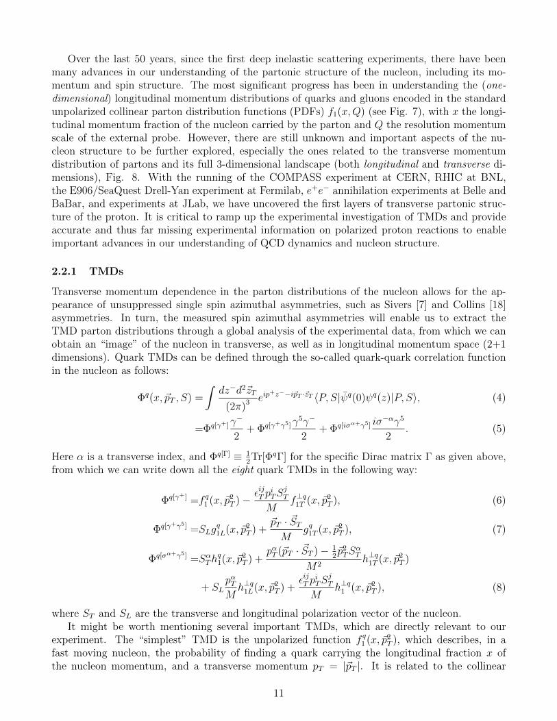
Transverse momentum dependence in the parton distributions of the nucleon allows for the ap-pearance of unsuppressed single spin azimuthal asymmetries, such as Sivers [7] and Collins [18]asymmetries. In turn, the measured spin azimuthal asymmetries will enable us to extract theTMD parton distributions through a global analysis of the experimental data, from which we canobtain an “image” of the nucleon in transverse, as well as in longitudinal momentum space (2+1dimensions). Quark TMDs can be defined through the so-called quark-quark correlation functionin the nucleon as follows:
Φq(x, ~pT , S) =
∫dz−d2~zT
(2π)3 eip+z−−i~pT ·~zT 〈P, S|ψq(0)ψq(z)|P, S〉, (4)
=Φq[γ+]γ−
2+ Φq[γ+γ5]γ
5γ−
2+ Φq[iσα+γ5] iσ
−αγ5
2. (5)
Here α is a transverse index, and Φq[Γ] ≡ 12Tr[ΦqΓ] for the specific Dirac matrix Γ as given above,
from which we can write down all the eight quark TMDs in the following way:
Φq[γ+] =f q1 (x, ~p2T )− εijT p
iTS
jT
Mf⊥q1T (x, ~p2
T ), (6)
Φq[γ+γ5] =SLgq1L(x, ~p2
T ) +~pT · ~STM
gq1T (x, ~p2T ), (7)
Φq[σα+γ5] =SαThq1(x, ~p2
T ) +pαT (~pT · ~ST )− 1
2~p2TS
αT
M2h⊥q1T (x, ~p2
T )
+ SLpαTMh⊥q1L(x, ~p2
T ) +εijT p
iTS
jT
Mh⊥q1 (x, ~p2
T ), (8)
where ST and SL are the transverse and longitudinal polarization vector of the nucleon.It might be worth mentioning several important TMDs, which are directly relevant to our
experiment. The “simplest” TMD is the unpolarized function f q1 (x, ~p2T ), which describes, in a
fast moving nucleon, the probability of finding a quark carrying the longitudinal fraction x ofthe nucleon momentum, and a transverse momentum pT = |~pT |. It is related to the collinear
11
ƒ1 =
g1L
=
h1 =
g1T
=ƒ1T
=
h1
=
h1L
=
h1T
=Sivers
Boer-Mulders
Helicity
Transversity
Leading Twist TMDs
Quark Polarization
Nu
cleo
n P
ola
riza
tio
n
Un-Polarized(U)
Longitudinally Polarized(L)
Transversely Polarized(T)
Nucleon Spin Quark Spin
—
—
—
—
—
—
—
U
L
T
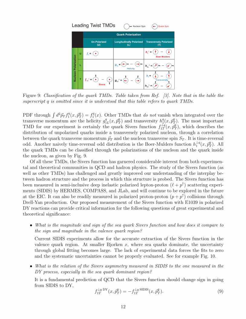
Figure 9: Classification of the quark TMDs. Table taken from Ref. [3]. Note that in the table thesuperscript q is omitted since it is understood that this table refers to quark TMDs.
PDF through∫d2~pTf
q1 (x, ~p2
T ) = f q1 (x). Other TMDs that do not vanish when integrated over thetransverse momentum are the helicity gq1L(x, ~p2
T ) and transversity hq1(x, ~p2T ). The most important
TMD for our experiment is certainly the quark Sivers function f⊥q1T (x, ~p2T ), which describes the
distribution of unpolarized quarks inside a transversely polarized nucleon, through a correlationbetween the quark transverse momentum ~pT and the nucleon transverse spin ST . It is time-reversalodd. Another naively time-reversal odd distribution is the Boer-Mulders function h⊥q1 (x, ~p2
T ). Allthe quark TMDs can be classified through the polarizations of the nucleon and the quark insidethe nucleon, as given by Fig. 9.
Of all these TMDs, the Sivers function has garnered considerable interest from both experimen-tal and theoretical communities in QCD and hadron physics. The study of the Sivers function (aswell as other TMDs) has challenged and greatly improved our understanding of the interplay be-tween hadron structure and the process in which this structure is probed. The Sivers function hasbeen measured in semi-inclusive deep inelastic polarized lepton-proton (` + p↑) scattering experi-ments (SIDIS) by HERMES, COMPASS, and JLab, and will continue to be explored in the futureat the EIC. It can also be readily measured in polarized proton-proton (p+ p↑) collisions throughDrell-Yan production. Our proposed measurement of the Sivers function with E1039 in polarizedDY reactions can provide critical information for the following questions of great experimental andtheoretical significance:
• What is the magnitude and sign of the sea quark Sivers function and how does it compare tothe sign and magnitude in the valence quark region?
Current SIDIS experiments allow for the accurate extraction of the Sivers function in thevalence quark region. At smaller Bjorken x, where sea quarks dominate, the uncertaintythrough global fitting becomes large. The lack of experimental data forces the fits to zeroand the systematic uncertainties cannot be properly evaluated. See for example Fig. 10.
• What is the relation of the Sivers asymmetry measured in SIDIS to the one measured in theDY process, especially in the sea quark dominant region?
It is a fundamental prediction of QCD that the Sivers function should change sign in goingfrom SIDIS to DY,
f⊥q DY1T (x, ~p2
T ) = −f⊥q SIDIS1T (x, ~p2
T ). (9)
12
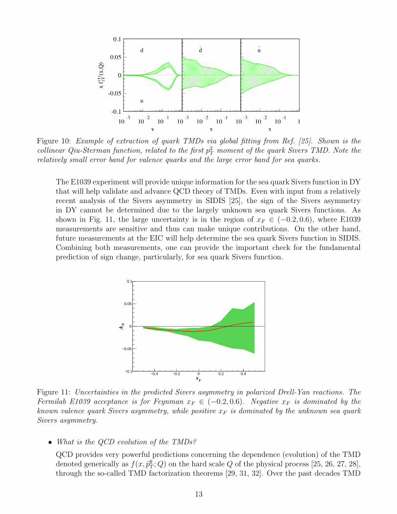
Figure 10: Example of extraction of quark TMDs via global fitting from Ref. [25]. Shown is thecollinear Qiu-Sterman function, related to the first p2
T moment of the quark Sivers TMD. Note therelatively small error band for valence quarks and the large error band for sea quarks.
The E1039 experiment will provide unique information for the sea quark Sivers function in DYthat will help validate and advance QCD theory of TMDs. Even with input from a relativelyrecent analysis of the Sivers asymmetry in SIDIS [25], the sign of the Sivers asymmetryin DY cannot be determined due to the largely unknown sea quark Sivers functions. Asshown in Fig. 11, the large uncertainty is in the region of xF ∈ (−0.2, 0.6), where E1039measurements are sensitive and thus can make unique contributions. On the other hand,future measurements at the EIC will help determine the sea quark Sivers function in SIDIS.Combining both measurements, one can provide the important check for the fundamentalprediction of sign change, particularly, for sea quark Sivers function.
Fx0.4− 0.2− 0 0.2 0.4
NA
0.1−
0.05−
0
0.05
0.1
ZhongBoCenter.txt
Figure 11: Uncertainties in the predicted Sivers asymmetry in polarized Drell-Yan reactions. TheFermilab E1039 acceptance is for Feynman xF ∈ (−0.2, 0.6). Negative xF is dominated by theknown valence quark Sivers asymmetry, while positive xF is dominated by the unknown sea quarkSivers asymmetry.
• What is the QCD evolution of the TMDs?
QCD provides very powerful predictions concerning the dependence (evolution) of the TMDdenoted generically as f(x, ~p2
T ;Q) on the hard scale Q of the physical process [25, 26, 27, 28],through the so-called TMD factorization theorems [29, 31, 32]. Over the past decades TMD
13
factorization formalism has been greatly improved using various approaches, see Refs. [33,34, 35, 36]. A unique feature of the TMD evolution distinctive from the usual collinear QCDevolution is the dependence on the non-perturbative aspects of gluon radiation. This can beeasily seen as follows: assuming one starts from a TMD f(x, ~p2
T ;Qi) measured at a lower scaleQi, and evolve to a TMD f(x, ~p2
T ;Qf ) at a higher scale Qf , the QCD evolution kernel shoulddepend on x, ~p2
T , Qi, Qf and is thus denoted as R(x, ~p2T , Qi, Qf ). As long as pT can be as
small as ΛQCD, which is the relevant region for TMDs, we are faced with a non-perturbativecontribution to the TMD evolution kernel.
Because of this, to understand the QCD evolution of TMDs and thus to extract TMDs inmuch better precision, it is essential to have experimental measurements at multiple scales.Current SIDIS measurements probe the low Q2 (few GeV2) and QT < 1 GeV region, whileW/Z production in p+ p↑ collisions probes the very high Q2 ' 1002 GeV2 and QT up to the10 GeV/c region. On the other hand, Drell-Yan measurements above the J/ψ peak fall in aunique region with Q2 in the range of 42 < M2 < 92 GeV 2 and QT ≤ few GeV. The E1039results will thus be highly complementary to those measurements for SIDIS and for W/Zproduction, and be critical to constrain the QCD evolution of TMDs.
2.2.2 Orbital Angular Momentum
There is compelling experimental evidence that the quark intrinsic angular momentum only con-tributes ∼ 1/3 of the proton spin. The majority of the proton spin is thus unaccounted for, whichhas been referred to as the “proton spin crisis” [37]. With recent experimental data from RHIC,it is fair to say that the sum of both quark and gluon spin contributions still cannot account forthe total proton spin [38]. The missing fraction of the spin (potentially very large) is likely to becarried by the orbital angular momentum (OAM) of the quarks and gluons.
Figure 12: Various contributions to the orbital angular momentum of nucleons as given by acalculation of K.F. Liu et al. [48].
14
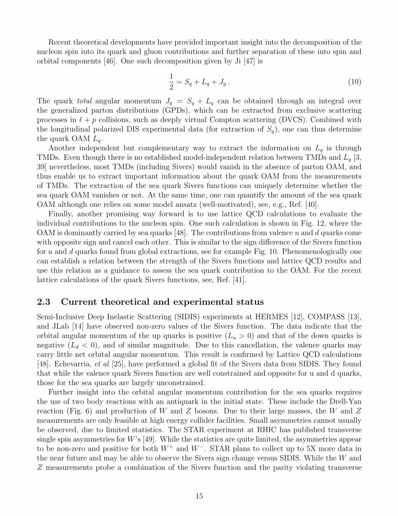
Recent theoretical developments have provided important insight into the decomposition of thenucleon spin into its quark and gluon contributions and further separation of these into spin andorbital components [46]. One such decomposition given by Ji [47] is
1
2= Sq + Lq + Jg . (10)
The quark total angular momentum Jq = Sq + Lq can be obtained through an integral overthe generalized parton distributions (GPDs), which can be extracted from exclusive scatteringprocesses in ` + p collisions, such as deeply virtual Compton scattering (DVCS). Combined withthe longitudinal polarized DIS experimental data (for extraction of Sq), one can thus determinethe quark OAM Lq.
Another independent but complementary way to extract the information on Lq is throughTMDs. Even though there is no established model-independent relation between TMDs and Lq [3,39] nevertheless, most TMDs (including Sivers) would vanish in the absence of parton OAM, andthus enable us to extract important information about the quark OAM from the measurementsof TMDs. The extraction of the sea quark Sivers functions can uniquely determine whether thesea quark OAM vanishes or not. At the same time, one can quantify the amount of the sea quarkOAM although one relies on some model ansatz (well-motivated), see, e.g., Ref. [40].
Finally, another promising way forward is to use lattice QCD calculations to evaluate theindividual contributions to the nucleon spin. One such calculation is shown in Fig. 12, where theOAM is dominantly carried by sea quarks [48]. The contributions from valence u and d quarks comewith opposite sign and cancel each other. This is similar to the sign difference of the Sivers functionfor u and d quarks found from global extractions, see for example Fig. 10. Phenomenologically onecan establish a relation between the strength of the Sivers functions and lattice QCD results anduse this relation as a guidance to assess the sea quark contribution to the OAM. For the recentlattice calculations of the quark Sivers functions, see, Ref. [41].
2.3 Current theoretical and experimental status
Semi-Inclusive Deep Inelastic Scattering (SIDIS) experiments at HERMES [12], COMPASS [13],and JLab [14] have observed non-zero values of the Sivers function. The data indicate that theorbital angular momentum of the up quarks is positive (Lu > 0) and that of the down quarks isnegative (Ld < 0), and of similar magnitude. Due to this cancellation, the valence quarks maycarry little net orbital angular momentum. This result is confirmed by Lattice QCD calculations[48]. Echevarria, et al [25], have performed a global fit of the Sivers data from SIDIS. They foundthat while the valence quark Sivers function are well constrained and opposite for u and d quarks,those for the sea quarks are largely unconstrained.
Further insight into the orbital angular momentum contribution for the sea quarks requiresthe use of two body reactions with an antiquark in the initial state. These include the Drell-Yanreaction (Fig. 6) and production of W and Z bosons. Due to their large masses, the W and Zmeasurements are only feasible at high energy collider facilities. Small asymmetries cannot usuallybe observed, due to limited statistics. The STAR experiment at RHIC has published transversesingle spin asymmetries for W ’s [49]. While the statistics are quite limited, the asymmetries appearto be non-zero and positive for both W+ and W−. STAR plans to collect up to 5X more data inthe near future and may be able to observe the Sivers sign change versus SIDIS. While the W andZ measurements probe a combination of the Sivers function and the parity violating transverse
15
helicity distribution, as mentioned previously, they are also carried out at much higher Q2. Drell-Yan production on fixed target experiments typically has higher integrated luminosity and arecarried out at a lower Q2. The COMPASS experiment at CERN [13] has performed transversesingle spin asymmetry measurements, with first results expected during this year. Due to thepresence of the antiquark in the pion beam, COMPASS is primarily sensitive to valence quarks inthe polarized target. Additional information summarizing the polarized Drell-Yan experiments atvarious laboratories around the world is given in Section 4 below.
Thus, no existing experiment is capable of directly measuring the Sivers asymmetry of thesea quarks with high precision. Our proposed E1039 experiment is based upon the proven E906spectrometer, which has already acquired large numbers of Drell-Yan events from liquid hydrogenand deuterium. LANL and UVa have recently completed and tested a new transversely polarizedproton target capable of both high polarization and integrated luminosity. We note that the E1027experiment at FNAL would instead use a transversely polarized beam with the E906 experiment, tomeasure the valence quark Sivers function, with a better figure of merit than COMPASS. Anotherunique capability of E1039 is the ability to separately measure the Sivers function for the d and uquarks using polarized NH3 and ND3 targets.
There are a few theoretical estimates available for the magnitude of the Sivers asymmetry inDrell-Yan, based on global fits to the existing SIDIS data. Anselmino, et al [59] and Sun and Yuan[28] predict central Sivers values ranging from 0. to 0.2 but have very large uncertainties, as shownin Fig. 22. More recently, Echevarria, et. al. [25], have confirmed that the fits to the existingdata are rather insensitive to contributions from the antiquarks, as shown in Fig. 10. Lattice QCDcalculations predict a large net orbital angular momentum contribution from the sea quarks [48].
2.4 The angular dependence of the Drell-Yan cross section
When studying the angular dependence of the proton induced Drell-Yan process, pp↑→ µ+µ−,three angles are of relevance: the azimuthal angle φS of the transverse spin orientation ST of thetarget (determined in the target rest frame) and the polar and azimuthal angles θ and φ of thedimuon pair (determined in the Collins-Soper frame [29], i.e. the dimuon center-of-mass system).The definition of the angles θ and φ is shown in Fig. 2. In the one-photon approximation, thedifferential cross section through the orientation dΩ of the dimuon pair can be decomposed in a
16

model-independent way [30] such that
dσ
d4q dΩ=
α2
4q2√
(Pb · Pt)2 −M2p [
(1 + cos2 θ)F 1UU + (1− cos2 θ)F 2
UU
+ sin 2θ cosφF cosφUU + sin2 θ cos 2φF cos 2φ
UU
]+ SL
[sin 2θ sinφF sinφ
UL + sin2 θ sin 2φF sin 2φUL
]+ ST
[sinφS
((1 + cos2 θ)F 1
UT + (1− cos2 θ)F 2UT
+ sin 2θ cosφF cosφUT + sin2 θ cos 2φF cos 2φ
UT
)+ cosφS
(sin 2θ sinφF sinφ
UT + sin2 θ sin 2φF cos 2φUT
) ].
(11)
Here, only partial cross sections are included where the polarization component ST (SL) of thetarget is transverse (longitudinal) to the direction of the virtual photon. The structure functionsF (Pb · q, Pt · q, q · q) depend on three independent Lorentz scalars calculated from the beam, targetand virtual photon momenta Pb, Pt and q. Their first and second subscripts indicate, respectively,the beam and target polarizations ((U)npolarized, (L)ongitudinally polarized, (T)ransversely po-larized). The related azimuthal modulation is given in a superscript. The Sivers mechanismmanifests itself in a sinφS (1 + cos2 θ) modulation in the cross section.
For small transverse momentum of the virtual photon, qT q, the process-dependent structurefunctions can be interpreted as convolution in transverse momentum space of the universal quarkand antiquark distributions of beam and target. At leading twist accuracy and at leading order inαS, the structure function F 1
UT provides a signal for the Sivers TMD f⊥1T in conjunction with thewell-known polarization-averaged PDF f1 of valence quarks such that
F 1UT = −C
[qT · kT,bqTMp
f1
(xt,k
2T,b
)f⊥1T(xb,k
2T,t
)]. (12)
Here, the convolution over the intrinsic transverse momenta kT of the quark and antiquark isrepresented by the symbol C.
The Sivers function can be experimentally constrained by a measurement of the angular dis-tribution of dimuon pairs produced in the Drell-Yan process with a transversely polarized target.The structure function F 1
UT is revealed in a sinφS (1 + cos2 θ) signature.In the following we present the simple expression extracting the asymmetry in LO. Taking
into account the dilution factor f , which describes the ratio of polarizable nucleons over the totalnumber of nucleons, and integrating over the virtual photon transverse momentum pT and thelepton pair angle Θ we can write the number of events in a xb and xT bin as :
dN(xb,xT ,φ,φS)dφdφS
= N(xb, xT )(
1 + 12Acos 2φUU cos 2φ
)+ fSL
12Asin 2φUL sin 2φ
+ f |ST |[AsinφSUT sinφS + 1
2
(A
sin(2φ+φS)UT sin(2φ+ φS)
+ Asin(2φ−φS)UT sin(2φ− φS)
)] (13)
17
Using the Fourier projection on the sinφS modulation finally gives
AsinφSUT =
2
f |ST |
∫dφSdφ
dN(xb,xT ,φ,φS)dφSdφ
sinφS
N(xb, xT ). (14)
This asymmetry is then connected to the structure function in Eq. 12
A sinφSUT =
F 1UT
F 1UU
. (15)
where the structure function F 1UU can be interpreted as a convolution in transverse momentum
space of the polarization averaged PDF for quarks and for antiquarks.
2.5 The Measurements
For the purpose of the proposed measurements, one needs to separately measure the Sivers functionfor u and d quarks. The approach we will follow is similar to that used previously by experimentsE866 and E906 to measure the d /u ratio in the proton. A transversely polarized proton targetis necessary for the u Sivers measurement, where the dominant Drell-Yan channel is a valence uquark from the unpolarized proton beam annihilating with a u (sea) quark from the target to formthe virtual photon. A transversely polarized deuteron target is used for the d Sivers measurement,with the neutron providing additional d assuming iso-spin symmetry.
A simultaneous measurement of the Sivers function for gluons is also possible with the polarizedproton target. Production of the J/ψ meson (a charmonium state) at small xF is primarily dueto gluon-gluon fusion. The J/ψ cross section and dimuon decay branch are large while the massof 3.097 GeV places it well within our experimental acceptance. This gluon Sivers measurementrequires no hardware changes to the experiment and is discussed further in Appendix C.2.
2.5.1 p + p↑
A dynamically polarized NH3 target is the optimum choice for a transversely polarized protontarget. While the dilution factor is small (0.18), due to the presence of a nitrogen atom, largepolarization values of greater than 95% for the protons can be obtained. Measurement of Drell-Yan events at forward rapidity (positive xF ) naturally selects u(beam) + u (target) with only asmall background from other quark combinations. The Sivers asymmetry is constructed from thenormalized difference of the cross sections for events with opposite target polarization. Most ofthe systematic errors can be canceled by reversing the target polarization or the magnetic fieldsof the spectrometer. The expected statistical error for a 1-yr NH3 measurement is ∼3% for thecentral x2 bins, while the systematic error is less than 1%.
2.5.2 p + d↑
ND3 can be used to provide the transversely polarized neutron target. Here the dilution factor ishigher (0.3), with a maximum polarization of up to 50%, leading to similar sensitivity as for theNH3 target. As for the proton target, events at forward rapidity select primarily sea quarks. Theadditional neutron in the deuteron increases the sensitivity to d under the assumption of iso-spinsymmetry. The Sivers d asymmetry is extracted from a comparison of the measured proton anddeuteron asymmetries. The expected statistical error for a 1-yr ND3 measurement is 4% for the
18
central xF bins, with a systematic error of less than 1%. Use of ND3 requires some changes toour existing polarized target. The Larmor (spin flip) frequency for deuterium is much lower thanfor hydrogen, 32 MHz versus 213 MHz, respectively, requiring a small modification of the NMRsystem used to measure the polarization.
Since the deuteron is a spin 1 nucleus, both vector and tensor polarizations are available. Thus,a measurement of the tensor structure function b1 is possible with the ND3 target as is discussedfurther in Appendix C.1.
3 Experimental Setup
3.1 The Spectrometer
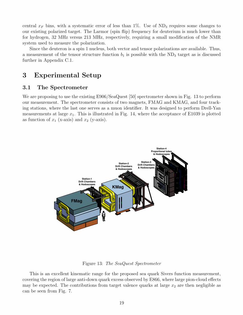
We are proposing to use the existing E906/SeaQuest [50] spectrometer shown in Fig. 13 to performour measurement. The spectrometer consists of two magnets, FMAG and KMAG, and four track-ing stations, where the last one serves as a muon identifier. It was designed to perform Drell-Yanmeasurements at large x1. This is illustrated in Fig. 14, where the acceptance of E1039 is plottedas function of x1 (x-axis) and x2 (y-axis).
FMag
KMag
Station-1Drift Chambers& Hodoscopes
Station-2Drift Chambers& Hodoscopes
Station-3Drift Chambers& Hodoscopes
Station-4Proportional tubes
& Hodoscopes
Figure 13: The SeaQuest Spectrometer
This is an excellent kinematic range for the proposed sea quark Sivers function measurement,covering the region of large anti-down quark excess observed by E866, where large pion-cloud effectsmay be expected. The contributions from target valence quarks at large x2 are then negligible ascan be seen from Fig. 7.
19
beamx0 0.1 0.2 0.3 0.4 0.5 0.6 0.7 0.8 0.9 1
targ
et
x
0
0.1
0.2
0.3
0.4
0.5
0.6
0.7
0.8
0.9
1
)ψM(J/
)ΥM(
Log scale in z
Figure 14: The kinematic acceptance of the E1039 experiment.
The experiment will be using the Fermilab main injector beam with an energy of 120 GeV anda 4 second spill every minute. The maximum beam intensity will be ' 1013 protons per spill.
3.2 The Polarized Target
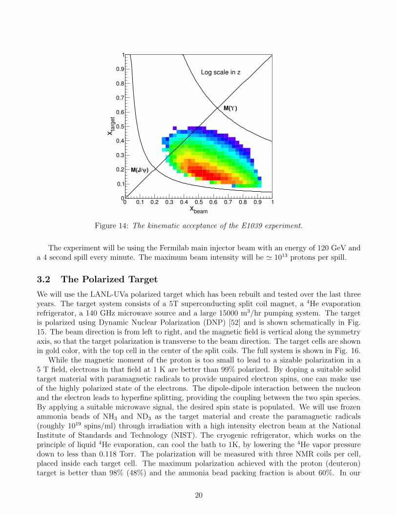
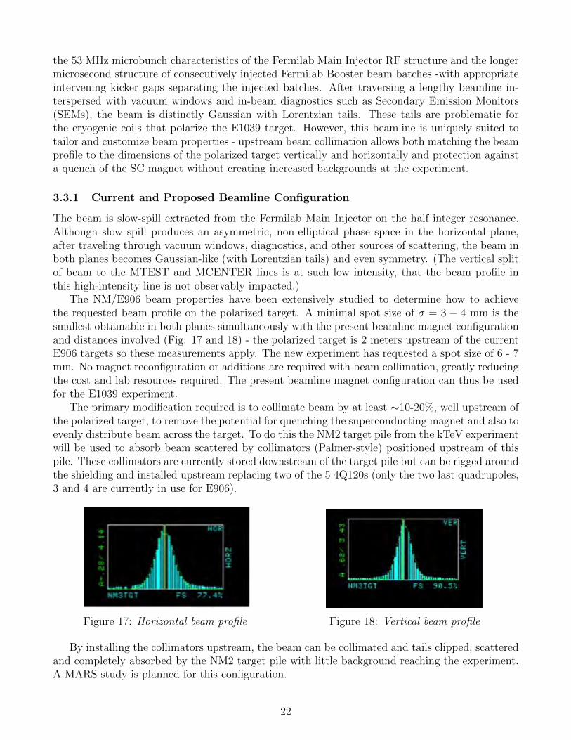
We will use the LANL-UVa polarized target which has been rebuilt and tested over the last threeyears. The target system consists of a 5T superconducting split coil magnet, a 4He evaporationrefrigerator, a 140 GHz microwave source and a large 15000 m3/hr pumping system. The targetis polarized using Dynamic Nuclear Polarization (DNP) [52] and is shown schematically in Fig.15. The beam direction is from left to right, and the magnetic field is vertical along the symmetryaxis, so that the target polarization is transverse to the beam direction. The target cells are shownin gold color, with the top cell in the center of the split coils. The full system is shown in Fig. 16.
While the magnetic moment of the proton is too small to lead to a sizable polarization in a5 T field, electrons in that field at 1 K are better than 99% polarized. By doping a suitable solidtarget material with paramagnetic radicals to provide unpaired electron spins, one can make useof the highly polarized state of the electrons. The dipole-dipole interaction between the nucleonand the electron leads to hyperfine splitting, providing the coupling between the two spin species.By applying a suitable microwave signal, the desired spin state is populated. We will use frozenammonia beads of NH3 and ND3 as the target material and create the paramagnetic radicals(roughly 1019 spins/ml) through irradiation with a high intensity electron beam at the NationalInstitute of Standards and Technology (NIST). The cryogenic refrigerator, which works on theprinciple of liquid 4He evaporation, can cool the bath to 1K, by lowering the 4He vapor pressuredown to less than 0.118 Torr. The polarization will be measured with three NMR coils per cell,placed inside each target cell. The maximum polarization achieved with the proton (deuteron)target is better than 98% (48%) and the ammonia bead packing fraction is about 60%. In our
20
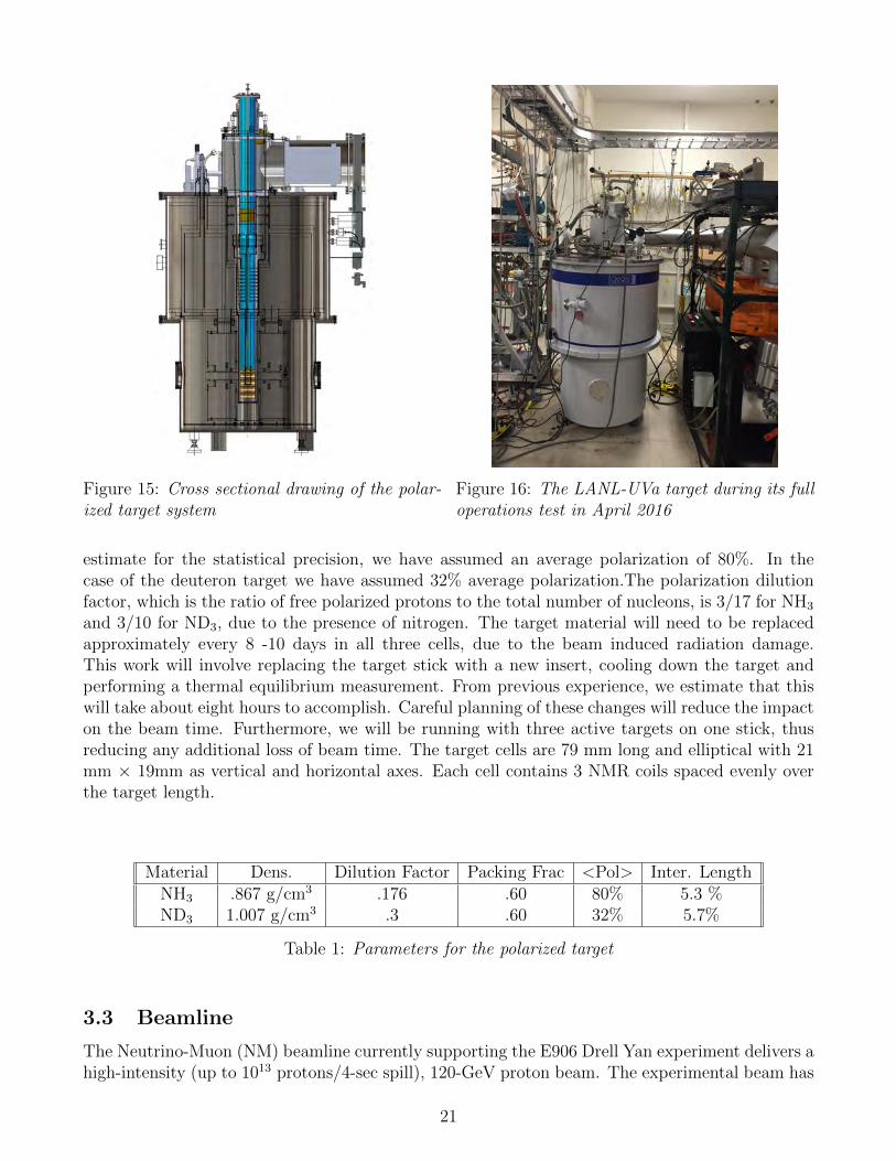
Figure 15: Cross sectional drawing of the polar-ized target system
Figure 16: The LANL-UVa target during its fulloperations test in April 2016
estimate for the statistical precision, we have assumed an average polarization of 80%. In thecase of the deuteron target we have assumed 32% average polarization.The polarization dilutionfactor, which is the ratio of free polarized protons to the total number of nucleons, is 3/17 for NH3
and 3/10 for ND3, due to the presence of nitrogen. The target material will need to be replacedapproximately every 8 -10 days in all three cells, due to the beam induced radiation damage.This work will involve replacing the target stick with a new insert, cooling down the target andperforming a thermal equilibrium measurement. From previous experience, we estimate that thiswill take about eight hours to accomplish. Careful planning of these changes will reduce the impacton the beam time. Furthermore, we will be running with three active targets on one stick, thusreducing any additional loss of beam time. The target cells are 79 mm long and elliptical with 21mm × 19mm as vertical and horizontal axes. Each cell contains 3 NMR coils spaced evenly overthe target length.
Material Dens. Dilution Factor Packing Frac <Pol> Inter. LengthNH3 .867 g/cm3 .176 .60 80% 5.3 %ND3 1.007 g/cm3 .3 .60 32% 5.7%
Table 1: Parameters for the polarized target
3.3 Beamline
The Neutrino-Muon (NM) beamline currently supporting the E906 Drell Yan experiment delivers ahigh-intensity (up to 1013 protons/4-sec spill), 120-GeV proton beam. The experimental beam has
21
the 53 MHz microbunch characteristics of the Fermilab Main Injector RF structure and the longermicrosecond structure of consecutively injected Fermilab Booster beam batches -with appropriateintervening kicker gaps separating the injected batches. After traversing a lengthy beamline in-terspersed with vacuum windows and in-beam diagnostics such as Secondary Emission Monitors(SEMs), the beam is distinctly Gaussian with Lorentzian tails. These tails are problematic forthe cryogenic coils that polarize the E1039 target. However, this beamline is uniquely suited totailor and customize beam properties - upstream beam collimation allows both matching the beamprofile to the dimensions of the polarized target vertically and horizontally and protection againsta quench of the SC magnet without creating increased backgrounds at the experiment.
3.3.1 Current and Proposed Beamline Configuration
The beam is slow-spill extracted from the Fermilab Main Injector on the half integer resonance.Although slow spill produces an asymmetric, non-elliptical phase space in the horizontal plane,after traveling through vacuum windows, diagnostics, and other sources of scattering, the beam inboth planes becomes Gaussian-like (with Lorentzian tails) and even symmetry. (The vertical splitof beam to the MTEST and MCENTER lines is at such low intensity, that the beam profile inthis high-intensity line is not observably impacted.)
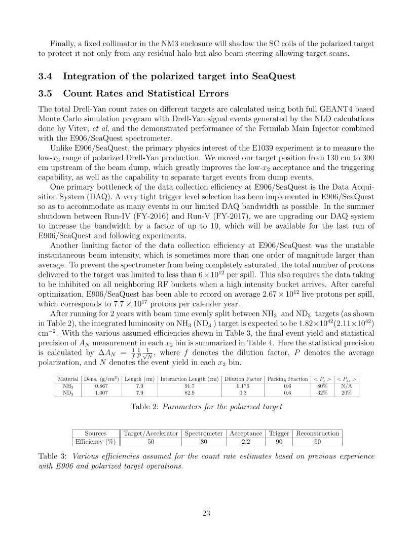
The NM/E906 beam properties have been extensively studied to determine how to achievethe requested beam profile on the polarized target. A minimal spot size of σ = 3 − 4 mm is thesmallest obtainable in both planes simultaneously with the present beamline magnet configurationand distances involved (Fig. 17 and 18) - the polarized target is 2 meters upstream of the currentE906 targets so these measurements apply. The new experiment has requested a spot size of 6 - 7mm. No magnet reconfiguration or additions are required with beam collimation, greatly reducingthe cost and lab resources required. The present beamline magnet configuration can thus be usedfor the E1039 experiment.
The primary modification required is to collimate beam by at least ∼10-20%, well upstream ofthe polarized target, to remove the potential for quenching the superconducting magnet and also toevenly distribute beam across the target. To do this the NM2 target pile from the kTeV experimentwill be used to absorb beam scattered by collimators (Palmer-style) positioned upstream of thispile. These collimators are currently stored downstream of the target pile but can be rigged aroundthe shielding and installed upstream replacing two of the 5 4Q120s (only the two last quadrupoles,3 and 4 are currently in use for E906).
Figure 17: Horizontal beam profile Figure 18: Vertical beam profile
By installing the collimators upstream, the beam can be collimated and tails clipped, scatteredand completely absorbed by the NM2 target pile with little background reaching the experiment.A MARS study is planned for this configuration.
22
Finally, a fixed collimator in the NM3 enclosure will shadow the SC coils of the polarized targetto protect it not only from any residual halo but also beam steering allowing target scans.
3.4 Integration of the polarized target into SeaQuest
3.5 Count Rates and Statistical Errors
The total Drell-Yan count rates on different targets are calculated using both full GEANT4 basedMonte Carlo simulation program with Drell-Yan signal events generated by the NLO calculationsdone by Vitev, et al, and the demonstrated performance of the Fermilab Main Injector combinedwith the E906/SeaQuest spectrometer.
Unlike E906/SeaQuest, the primary physics interest of the E1039 experiment is to measure thelow-x2 range of polarized Drell-Yan production. We moved our target position from 130 cm to 300cm upstream of the beam dump, which greatly improves the low-x2 acceptance and the triggeringcapability, as well as the capability to separate target events from dump events.
One primary bottleneck of the data collection efficiency at E906/SeaQuest is the Data Acqui-sition System (DAQ). A very tight trigger level selection has been implemented in E906/SeaQuestso as to accommodate as many events in our limited DAQ bandwidth as possible. In the summershutdown between Run-IV (FY-2016) and Run-V (FY-2017), we are upgrading our DAQ systemto increase the bandwidth by a factor of up to 10, which will be available for the last run ofE906/SeaQuest and following experiments.
Another limiting factor of the data collection efficiency at E906/SeaQuest was the unstableinstantaneous beam intensity, which is sometimes more than one order of magnitude larger thanaverage. To prevent the spectrometer from being completely saturated, the total number of protonsdelivered to the target was limited to less than 6×10¹² per spill. This also requires the data takingto be inhibited on all neighboring RF buckets when a high intensity bucket arrives. After carefuloptimization, E906/SeaQuest has been able to record on average 2.67× 10¹² live protons per spill,which corresponds to 7.7× 10¹⁷ protons per calender year.
After running for 2 years with beam time evenly split between NH3 and ND3 targets (as shownin Table 2), the integrated luminosity on NH3 (ND3 ) target is expected to be 1.82×1042(2.11×1042)cm−2. With the various assumed efficiencies shown in Table 3, the final event yield and statisticalprecision of AN measurement in each x2 bin is summarized in Table 4. Here the statistical precisionis calculated by ∆AN = 1
f1P
1√N
, where f denotes the dilution factor, P denotes the averagepolarization, and N denotes the event yield in each x2 bin.
Material Dens. (g/cm3) Length (cm) Interaction Length (cm) Dilution Factor Packing Fraction < Pz > < Pzz >NH3 0.867 7.9 91.7 0.176 0.6 80% N/AND3 1.007 7.9 82.9 0.3 0.6 32% 20%
Table 2: Parameters for the polarized target
Sources Target/Accelerator Spectrometer Acceptance Trigger ReconstructionEfficiency (%) 50 80 2.2 90 60
Table 3: Various efficiencies assumed for the count rate estimates based on previous experiencewith E906 and polarized target operations.
23
x2 bin < x2 >NH3 (p↑) ND3 (d↑) n↑
N ∆A (%) N ∆A (%) ∆A(%)0.10 - 0.16 0.139 5.0× 10⁴ 3.2 5.8× 10⁴ 4.3 5.40.16 - 0.19 0.175 4.5× 10⁴ 3.3 5.2× 10⁴ 4.6 5.70.19 - 0.24 0.213 5.7× 10⁴ 2.9 6.6× 10⁴ 4.1 5.00.24 - 0.60 0.295 5.5× 10⁴ 3.0 6.4× 10⁴ 4.1 5.1
Table 4: Event yield and statistical precision of the AN measurement in each of the x2 bins for theNH3 (p↑) and ND3 (d↑) targets, and the deduced AN measurement precision for polarized n.
3.6 Polarization Measurements
3.6.1 Proton Polarization Measurements
The proton spin polarization is measured with a continuous-wave NMR system based on theLiverpool Q-meter design [51] and recently upgraded at LANL. The Q-meter works as part of acircuit with phase sensitivity designed to respond to the change of the impedance in the NMRcoil. The radio-frequent (RF) susceptibility of the material is inductively coupled to the NMR coilwhich is part of a series LCR circuit, tuned to the Larmor frequency of the nuclei being probed.The output, consisting of a DC level digitized and recorded as a target event [52] in the targetdata acquisition system.
The polarized target NMR and data acquisition includes the software control system, the Rohde& Schwarz RF generator (R&S), the Q-meter enclosure, and the target cavity insert. The Q-meterenclosure is a standard VME crate, containing a series of Q-meter circuit boards with separateconnection cables which are used for different target cup cells during the experiment. The targetmaterial and NMR coil are held in polychlorotrifluorethylene (Kel-F) cells with the whole targetinsert cryogenically cooled to 1 K. Kel-F is used because it contains no free protons.
The R&S generator produces a RF signal which is frequency modulated to sweep over thefrequency range of interest. Typically, the R&S responds to an external modulation, sweepinglinearly from 400 kHz below to 400 kHz above the Larmor frequency. The signal from the R&Sis connected to the NMR coils within the target material. To avoid degrading reflections in thelong connection from the NMR coil to the electronics, a standing wave can be created in thetransmission cable by selecting a length of cable that is an integer multiple of the half-wavelengthof the resonant frequency. This specialized connection cable is known as the λ/2 cable and is asemi-rigid cable with a teflon based dielectric. The NMR coil consists of a set of loops made of70/30 copper-nickel tube, which minimizes interaction with the proton beam. The coil opens upinto an oval shape spanning approximately 2 cm inside the cup. It is possible to enhance the signalto noise ratio by taking multiple frequency sweeps and averaging the signals. A completion of theset number of sweeps results in a single target event with a time stamp. The averaged signal isintegrated to obtain a NMR polarization area for that event. Each target event written containsall NMR system parameters and the target environment variables needed to calculate the finalpolarization.
A target NMR calibration measurement or Thermal Equilibrium measurement (TE) is used tofind a proportionality relation to determine the enhanced polarization under a range of thermalconditions given the area of the “Q-curve” NMR signal at the same magnetic field. The magneticmoment in the external field results in a set of 2J+1 energy sublevels through Zeeman interaction,
24
where J is the particle spin. The TE natural polarization for a spin-1/2 particle is given by,
PTE = tanh
(µB
kT
), (16)
coming from Curie’s Law [54], where µ is the magnetic moment in the external field of strength B,k is the Boltzmann constant, and T the temperature. Measuring PTE at low temperature increasesstability and the polarization signal. This is favorable because the uncertainty in the NMR signalincreases as the area of the signal decreases. In fact much of the polarization uncertainty comesfrom this measurement. The goal temperature used is ∼1.4 K.
The dynamic polarization value is derived by comparing the enhanced signal SE integratedover the driving frequency ω, with that of the TE signal:
PE = G
∫SE(ω)dω∫STE(ω)dω
PTE = GCTEAE, (17)
and calibration constant defined as,
CTE =PTEATE
. (18)
PE (AE) is the polarization (area) of the enhanced signal and PTE (ATE) is the polarization(area) from the thermal equilibrium measurement. The uncertainty in the calibration constant,δCTE/CTE, can easily be calculated using the fractional error from PTE and ATE. The ratio ofgains from the NMR card used during the thermal equilibrium measurement to the enhanced signalis represented as G. For more detail, see [53].
3.6.2 Neutron Polarization Measurements
The deuteron polarization will be monitored by the same LANL continuous wave NMR system asused for the proton with one small change. There are two means whereby the polarization can beextracted from the NMR signal: the area method and the peak-height method. We intend to useboth.
First, the total area of the NMR absorption signal is proportional to the vector polarizationof the sample, and the constant of proportionality can be calibrated against the polarization ofthe sample measured under thermal equilibrium conditions. This is the standard method used forpolarized proton targets, but can be more problematic for deuteron targets. Typical conditionsfor the TE measurements are 5 T and 1.4 K, where the deuteron polarization is only 0.075%,compared to 0.36% for protons. This smaller polarization, along with quadruple broadening,makes the deuteron TE signal more difficult to measure with high accuracy. A cold NMR systemcan be used to improve the signal-to-noise ratio of the NMR signal [55].
The deuteron polarization can also be extracted from the shape of the NMR signal. Thedeuteron is a spin-1 nucleus with three magnetic substates, m = −1, 0,+1, and the NMR absorp-tion signal lineshape is the sum of the two overlapping absorption lines consisting of the −1 → 0and 0→ +1 transitions. In the case of ND3, the deuteron’s electric quadrupole moment interactswith electric field gradients within the molecule and splits the degeneracy of the two transitions.The degree of splitting depends on the angle between the magnetic field and direction of theelectric field gradient. The resultant lineshape, integrated over a sample of many polycrystallinebeads has the form of a Pake doublet. It has been experimentally demonstrated that, at or nearsteady-state conditions, the magnetic substates of deuterons in dynamically polarized ND3 are
25
populated according to the Boltzmann distribution with a characteristic spin temperature T thatcan be either positive or negative, depending on the sign of the polarization.
When the system is at thermal equilibrium with the solid lattice, the deuteron polarization isknown from:
Pz =4 + tanh µB
2kT
3 + tanh2 µB2kT
(19)
where µ is the magnetic moment, and k is Boltzmann’s constant. The vector polarization canbe determined by comparing the enhanced signal with that of the TE signal (which has knownpolarization). This polarimetry method is typically reliable to about 5% relative.
Similarly, the tensor polarization is given by:
Pzz =4 + tanh2 µB
2kT
3 + tanh2 µB2kT
(20)
From Eqs. 19 and 20, we find:Pzz = 2−
√4− 3P 2
z (21)
In addition to the TE method, polarizations can be determined by analyzing NMR lineshapesas described in [57] with a typical 5-7% relative uncertainty. At high polarizations, the intensitiesof the two transitions differ, and the NMR signal shows an asymmetry R in the value of the twopeaks. The vector polarization is then given by:
Pz =R2 − 1
R2 +R + 1(22)
and the tensor polarization is given by:
Pzz =R2 − 2R + 1
R2 +R + 1(23)
This measuring technique can be used as a compliment to the TE method resulting in reduceduncertainty in polarization for vector polarizations over 28%.
The measurement of the neutron polarization (Pn) is achieved by a calculation using the NMRmeasured polarization of the deuteron (Pd). The quantum mechanical calculation using Clebsch-Gordan coefficients show 75% of the neutron spins in the D-state are antiparallel to the deuteronspins [56]. The resulting neutron polarization is,
Pn = (1− 1.5αD)Pd ≈ 0.91Pd,
where αD is the probability of the deuteron to be in a D-state.
3.6.3 Target Polarization Uncertainty
The lower limit for polarization uncertainty is set by the Q-meter style NMR which can not beexpected to preform better that 1% relative error. UVA test lab studies have gone down as far as1.5% but typically in an experiment 2-4% is achieved for the proton. The Deuteron/neutron hasmuch larger error but with the use of the cold NMR system [55] in combination with the multiplemeasurement techniques it is also possible to get down into the same uncertainty region as theproton.
26
3.6.4 Active Target Contributions
The figure of merit for this type of polarized target experiment is proportional to the active targetcontribution squared times polarization squared. The active target contribution is made of of thedilution factor and the packing fraction over the length of the target. The packing fraction canbe determined using a method of cryogenic volume displacement measurement which compare anempty target cell to the full target cell used in the experiment. The target cell is filled with beadsof solid NH3 material with a typical packing factor of about 60% with the rest of the space filledwith liquid helium.
The dilution factor is the ratio of the number of polarizable nucleons to the total number ofnucleons in the target material and can be defined as,
f =NDσD,H
NNσN +NDσD + ΣNAσA, (24)
where ND is the number of deuteron nuclei in the target and σD is the corresponding inclusivedouble differential scattering cross section, NN is the nitrogen number of scattered nuclei withcross section σN , and NA is the numbers of other scattering nuclei of mass number A with crosssection σA. The denominator of the dilution factor can be written in terms of the relative volumeratio of ND3 to LHe in the target cell, the packing fraction pf . For the case of a cylindrical targetcell oriented along the magnetic field, the packing fraction is exactly equivalent to the percentageof the cell length filled with NH3 or ND3. The dilution factor for NH3 is 0.176 and for ND3 is 0.3.The uncertainty in these factors from irreducible background is typically 2-3%.
3.7 Luminosity and Beam Intensity Uncertainty
3.7.1 Beam Profile
The typical profile of the beam delivered to the target is a two dimensional Gaussian withσx = 6.8 mm, σy = 7.6 mm. The beam will be clipped with collimators at ±1.25σ, giving a beamprofile of ∆x= 17 mm, ∆y= 19 mm (see left plot in Fig. 19). The beam is expected to drift nomore than ±2 mm in the x-direction before collimation. The change of the luminosity of the beamdue to the beam drifting is (Nbeam −Ndrift) /Nbeam. The right plot in Fig. 19 demonstrates thatfor a beam drift of xdrift = 2 mm, the change in the delivered Luminosity is ∆L= 2.8%.
3.7.2 Luminosity measurement
Several detector and measurement techniques are used in order to control systematic uncertaintiesfrom changing beam conditions, such as position, luminosity and shape. The absolute beamintensity will be determined by the Unser Monitors upstream of the target. The accuracy of UnserMonitors has been established to be 0.05% [58].
Four detectors at 90 to the beam (two horizontally and two vertically) will help monitorthe instantaneous luminosity. Each of these detectors will consist of four plastic scintillators incoincidence and positioned outside of the shielding wall, pointing through a small hole in theshielding at the target. Fast MC simulations show that these detectors will detect π±s, µ±s, γswith E> 100 MeV on the order of ∼200 kHz.
The ratio of every one of these detectors over the Unser Monitor measurement (N90/Nunser)will provide a fast relative luminosity measurement. If part of the beam profile deviates off thetarget after the Unser measurement (see example in Fig. 20), the 90 detectors will be able detect
27
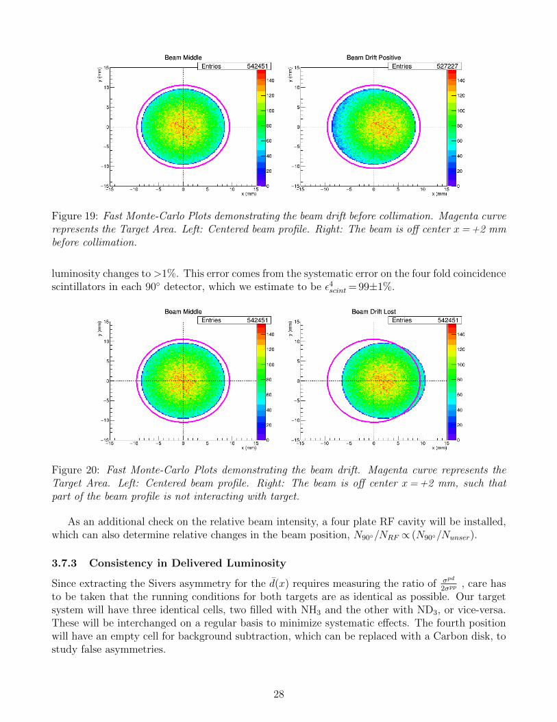
Figure 19: Fast Monte-Carlo Plots demonstrating the beam drift before collimation. Magenta curverepresents the Target Area. Left: Centered beam profile. Right: The beam is off center x= +2 mmbefore collimation.
luminosity changes to >1%. This error comes from the systematic error on the four fold coincidencescintillators in each 90 detector, which we estimate to be ε4scint = 99±1%.
Figure 20: Fast Monte-Carlo Plots demonstrating the beam drift. Magenta curve represents theTarget Area. Left: Centered beam profile. Right: The beam is off center x= +2 mm, such thatpart of the beam profile is not interacting with target.
As an additional check on the relative beam intensity, a four plate RF cavity will be installed,which can also determine relative changes in the beam position, N90/NRF ∝ (N90/Nunser).
3.7.3 Consistency in Delivered Luminosity
Since extracting the Sivers asymmetry for the d(x) requires measuring the ratio of σpd
2σpp, care has
to be taken that the running conditions for both targets are as identical as possible. Our targetsystem will have three identical cells, two filled with NH3 and the other with ND3, or vice-versa.These will be interchanged on a regular basis to minimize systematic effects. The fourth positionwill have an empty cell for background subtraction, which can be replaced with a Carbon disk, tostudy false asymmetries.
28
3.8 Spectrometer Induced Uncertainities
A further source of systematic uncertainty may come from the muon spectrometer. Geometricalacceptance and effects on dimuon reconstruction due to temperature and pressure changes mayhave an effect on the measurement of the Drell-Yan AN . To estimate the systematic uncertaintyin the AN measurement due to these changes in the spectrometer, the raw asymmetry of dimuonsin the existing E906 data was used. A high statistics sample of the E906 data with stable runningconditions was used for this study. An up-down spin direction was assigned randomly after a givenlength of data (e.g. one day), and the raw left-right asymmetry was calculated using the so calledsquare-root formula.
εsqrt(φ) =
√N↑(φ) ·N↓(φ+ π)−
√N↓(φ) ·N↑(φ+ π)√
N↑(φ) ·N↓(φ+ π) +√N↓(φ) ·N↑(φ+ π)
(25)
This process was repeated 5000 times. With random assignment of the spin direction, a Gaus-sian distribution centered around zero is expected. The RMS of the Gaussian should correspondto the statistical + systematic uncertainty due to the spectrometer, RMS2 =σ2
stat + σ2syst. In order
to estimate this error for the E1039 data, we need to take
σE1039,syst
σE1039,stat
=σsystσstat
(26)
σE1039,syst =
(σsystσstat
)× σE1039,stat, (27)
so the absolute systematic error on the spectrometer will scale with the total statistical error.The study was repeated five times, changing the length of data between spin assignments each
time. An example of the Gaussian distribution for changing the spin direction once a day is shownin Fig. 21. The results are summarized in Table 5.
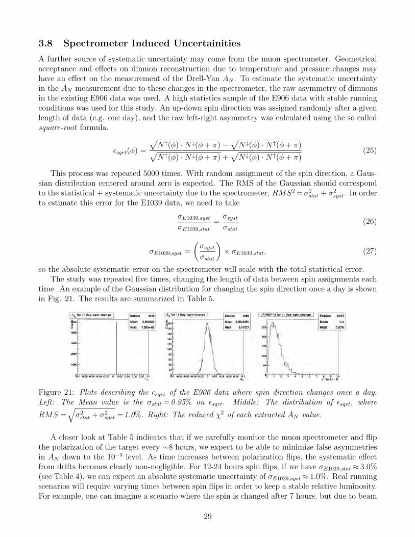
Figure 21: Plots describing the εsqrt of the E906 data where spin direction changes once a day.Left: The Mean value is the σstat = 0.95% on εsqrt. Middle: The distribution of εsqrt, where
RMS =√σ2stat + σ2
syst = 1.0%. Right: The reduced χ2 of each extracted AN value.
A closer look at Table 5 indicates that if we carefully monitor the muon spectrometer and flipthe polarization of the target every ∼8 hours, we expect to be able to minimize false asymmetriesin AN down to the 10−3 level. As time increases between polarization flips, the systematic effectfrom drifts becomes clearly non-negligible. For 12-24 hours spin flips, if we have σE1039,stat≈ 3.0%(see Table 4), we can expect an absolute systematic uncertainty of σE1039,syst≈ 1.0%. Real runningscenarios will require varying times between spin flips in order to keep a stable relative luminosity.For example, one can imagine a scenario where the spin is changed after 7 hours, but due to beam
29
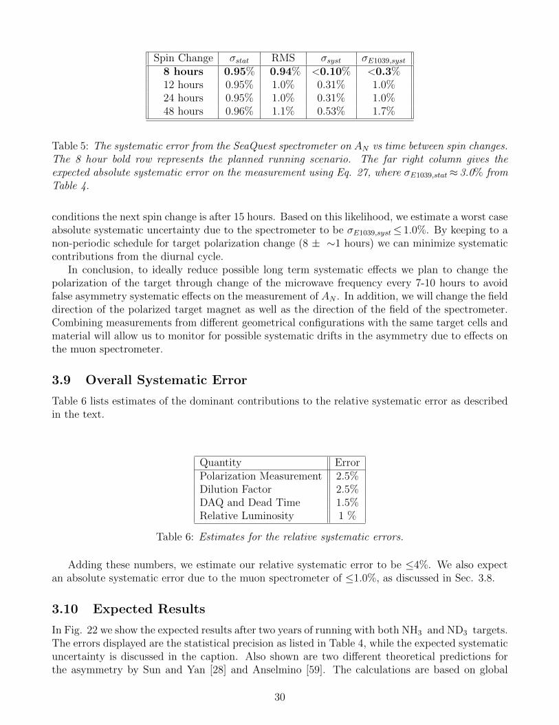
Spin Change σstat RMS σsyst σE1039,syst
8 hours 0.95% 0.94% <0.10% <0.3%12 hours 0.95% 1.0% 0.31% 1.0%24 hours 0.95% 1.0% 0.31% 1.0%48 hours 0.96% 1.1% 0.53% 1.7%
Table 5: The systematic error from the SeaQuest spectrometer on AN vs time between spin changes.The 8 hour bold row represents the planned running scenario. The far right column gives theexpected absolute systematic error on the measurement using Eq. 27, where σE1039,stat≈ 3.0% fromTable 4.
conditions the next spin change is after 15 hours. Based on this likelihood, we estimate a worst caseabsolute systematic uncertainty due to the spectrometer to be σE1039,syst≤ 1.0%. By keeping to anon-periodic schedule for target polarization change (8 ± ∼1 hours) we can minimize systematiccontributions from the diurnal cycle.
In conclusion, to ideally reduce possible long term systematic effects we plan to change thepolarization of the target through change of the microwave frequency every 7-10 hours to avoidfalse asymmetry systematic effects on the measurement of AN . In addition, we will change the fielddirection of the polarized target magnet as well as the direction of the field of the spectrometer.Combining measurements from different geometrical configurations with the same target cells andmaterial will allow us to monitor for possible systematic drifts in the asymmetry due to effects onthe muon spectrometer.
3.9 Overall Systematic Error
Table 6 lists estimates of the dominant contributions to the relative systematic error as describedin the text.
Quantity ErrorPolarization Measurement 2.5%Dilution Factor 2.5%DAQ and Dead Time 1.5%Relative Luminosity 1 %
Table 6: Estimates for the relative systematic errors.
Adding these numbers, we estimate our relative systematic error to be ≤4%. We also expectan absolute systematic error due to the muon spectrometer of ≤1.0%, as discussed in Sec. 3.8.
3.10 Expected Results
In Fig. 22 we show the expected results after two years of running with both NH3 and ND3 targets.The errors displayed are the statistical precision as listed in Table 4, while the expected systematicuncertainty is discussed in the caption. Also shown are two different theoretical predictions forthe asymmetry by Sun and Yan [28] and Anselmino [59]. The calculations are based on global
30
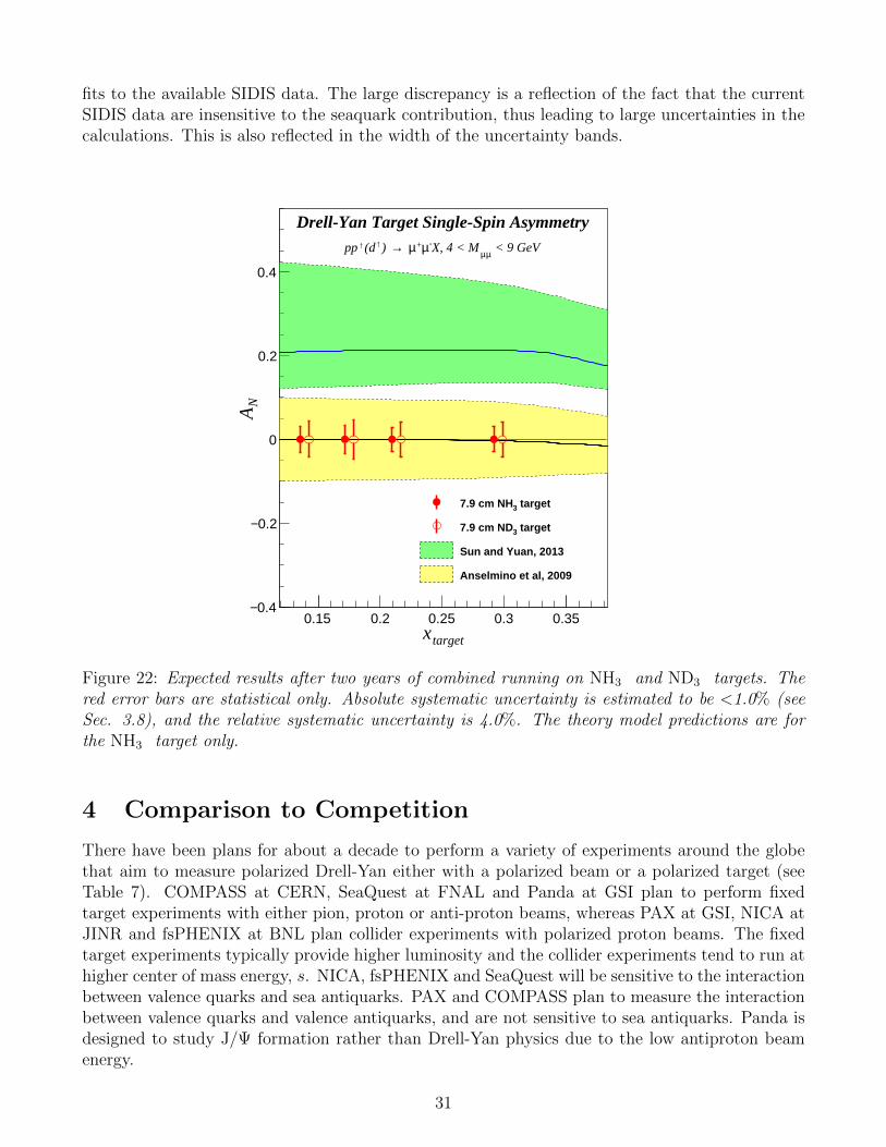
fits to the available SIDIS data. The large discrepancy is a reflection of the fact that the currentSIDIS data are insensitive to the seaquark contribution, thus leading to large uncertainties in thecalculations. This is also reflected in the width of the uncertainty bands.
targetx0.15 0.2 0.25 0.3 0.35
NA
0.4−
0.2−
0
0.2
0.4
Drell-Yan Target Single-Spin Asymmetry < 9 GeVµµX, 4 < M-µ+µ →) ↑(d↑pp
target37.9 cm NH
target37.9 cm ND
Sun and Yuan, 2013
Anselmino et al, 2009
Figure 22: Expected results after two years of combined running on NH3 and ND3 targets. Thered error bars are statistical only. Absolute systematic uncertainty is estimated to be <1.0% (seeSec. 3.8), and the relative systematic uncertainty is 4.0%. The theory model predictions are forthe NH3 target only.
4 Comparison to Competition
There have been plans for about a decade to perform a variety of experiments around the globethat aim to measure polarized Drell-Yan either with a polarized beam or a polarized target (seeTable 7). COMPASS at CERN, SeaQuest at FNAL and Panda at GSI plan to perform fixedtarget experiments with either pion, proton or anti-proton beams, whereas PAX at GSI, NICA atJINR and fsPHENIX at BNL plan collider experiments with polarized proton beams. The fixedtarget experiments typically provide higher luminosity and the collider experiments tend to run athigher center of mass energy, s. NICA, fsPHENIX and SeaQuest will be sensitive to the interactionbetween valence quarks and sea antiquarks. PAX and COMPASS plan to measure the interactionbetween valence quarks and valence antiquarks, and are not sensitive to sea antiquarks. Panda isdesigned to study J/Ψ formation rather than Drell-Yan physics due to the low antiproton beamenergy.
31
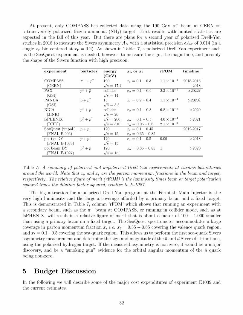
At present, only COMPASS has collected data using the 190 GeV π− beam at CERN ona transversely polarized frozen ammonia (NH3) target. First results with limited statistics areexpected in the fall of this year. But there are plans for a second year of polarized Drell-Yanstudies in 2018 to measure the Sivers asymmetry AN with a statistical precision δAN of 0.014 (in asingle xF-bin centered at xF = 0.2). As shown in Table. 7, a polarized Drell-Yan experiment suchas the SeaQuest experiment is needed, however, to measure the sign, the magnitude, and possiblythe shape of the Sivers function with high precision.
experiment particles energy xb or xt rFOM timeline(GeV)
COMPASS π− + p↑ 190 xt = 0.1 – 0.3 1.1× 10⁻³ 2015-2016(CERN)
√s = 17.4 2018
PAX p↑ + p collider xb = 0.1 – 0.9 2.3× 10⁻⁵ >2022?(GSI)
√s = 14
PANDA p+ p↑ 15 xt = 0.2 – 0.4 1.1× 10⁻⁴ >2020?(GSI)
√s = 5.5
NICA p↑ + p collider xb = 0.1 – 0.8 6.8× 10⁻⁵ >2020(JINR)
√s = 20
fsPHENIX p↑ + p↑√s = 200 xb = 0.1 – 0.5 4.0× 10⁻⁴ >2021
(RHIC)√s = 510 xb = 0.05 – 0.6 2.1× 10⁻³
SeaQuest (unpol.) p+ p 120 xt = 0.1 – 0.45 − − 2012-2017(FNAL E-906)
√s = 15 xb = 0.35 – 0.85
pol tgt DY p+ p↑ 120 xt = 0.1 – 0.5 0.09 >2018(FNAL E-1039)
√s = 15
pol beam DY p↑ + p 120 xb = 0.35 – 0.85 1 >2020(FNAL E-1027)
√s = 15
Table 7: A summary of polarized and unpolarized Drell-Yan experiments at various laboratoriesaround the world. Note that xb and xt are the parton momentum fractions in the beam and target,respectively. The relative figure of merit (rFOM) is the luminosity times beam or target polarizationsquared times the dilution factor squared, relative to E-1027.
The big attraction for a polarized Drell-Yan program at the Fermilab Main Injector is thevery high luminosity and the large x-coverage afforded by a primary beam and a fixed target.This is demonstrated in Table 7, column ’rFOM’ which shows that running an experiment witha secondary beam, such as the π− beam at COMPASS, or running in collider mode, such as atfsPHENIX, will result in a relative figure of merit that is about a factor of 100 – 1,000 smallerthan using a primary beam on a fixed target. The SeaQuest spectrometer accommodates a largecoverage in parton momentum fraction x, i.e. xb = 0.35− 0.85 covering the valence quark region,and xt = 0.1−0.5 covering the sea quark region. This allows us to perform the first sea-quark Siversasymmetry measurement and determine the sign and magnitude of the u and d Sivers distributions,using the polarized hydrogen target. If the measured asymmetry is non-zero, it would be a majordiscovery, and be a “smoking gun” evidence for the orbital angular momentum of the u quarkbeing non-zero.
5 Budget Discussion
In the following we will describe some of the major cost expenditures of experiment E1039 andthe current estimates.
32
5.1 Liquefier System and Pump Installation
The major cryogenic issues with a polarized 4He target are the liquid He consumption and thecollection of the exhaust gas. Keeping the target at 1K while irradiating it with the microwaverequires evaporation of 100 liters of liquid He per day through pumping. Not recovering the Heliumgas after the ROOTS pumps would lead to wasting an unacceptable amount of a nonrenewableresource at a cost of $600,000 for two years of running. New DOE guidelines require us to installa closed loop Helium liquefier system. Furthermore, such a system needs special plumbing andrecovery infrastructure consisting of Helium and Nitrogen transfer lines, pumping lines from thetarget to the ROOTS pumps as well as a special quenchline, which would handle the Heliumexhaust gas in case of a magnet quench. We have identified two Linde L1410 liquefiers (one atFNAL and one at the University of Illinois), which we could have refurbished as part of a wholepackage. Quantum Technology (QT), in 2015, has provided us with a preliminary bid for a closedloop system, including rebuilding one of these liquefiers for $408,000. This quote assumed a cost of$30,000 for refurbishing these L1410s. However, a firm estimate for this can only be provided whenthe liquefier is at Quantum Technoloy and evaluated for the work needed (see quote in Appendix).In an independent, oral communication from Linde industries (the original manufacturer), the costfor rebuilding was quoted to us as up to $250,000. We have decided to use this higher estimatetogether with the closed loop system quote from Quantum Technology (removing the refurbishingamount from the QT quote) to estimate the total liquefier costs at $628,000.
The costs for the Helium and Nitrogen transfer lines is contingent on the final design andinstallation of the cryo system. While we have a preliminary design, this will need further detailedstudies in collaboration with FNAL ES&H personnel. The estimate for the liquid Helium andNitrogen transfer lines, based on the current design, is $50,000. The estimate for the Heliumpump lines is $20,000. The liquefier and the pump lines need two new dedicated 200A electricalcircuits to be installed as well as switches on the two magnets to flip the sign of the magneticfields, at a cost of $25,000.
5.2 Beam Line Changes
As described above, the modifications to the beamline will require the installation of two collimatorsin NM2 to shape the beam, as well as a collimator in NM3 to shield the superconducting coils ofthe target magnet. The current cost estimate for this is roughly $330,000, which is mainly labor.
5.3 Shielding and Target Cave Modifications
This cost can only be estimated once the final design of the shielding has been performed and thescope of the necessary work been determined. This will require close collaboration between ES&H, Accelerator and Physics divisions at FNAL with LANL engineering. The main cost of this willbe labor for stacking the E1039 shielding. The FNAL estimate for completely unstacking (whichis more than we would need) the SeaQuest shielding is $40,000. After the removal of the E906shielding the work on the new shielding configuration can commence. The FNAL provided laborcost estimate for this work is $300,000.
As described in the section on Integration, the target cave area has to be modified to allow forthe additional height required to change the target stick, as well as accomodating the move of thetarget further upstream. The FNAL provided estimate for this is $180,000 with $170,000 in labor.This will include the costs for installing the transfer lines.
33
5.4 Total Installation Costs
In the following we summarize the major costs associated with mounting the E1039 experiment atFermilab. We have split up the costs into equipment and labor needs as outlined. The costs arebased on quotes from vendors, previous purchases and estimates provided by FNAL personnel. Thecontingencies for items with quotes have been lowered, however in the case of Quantum Technology,we have increased the costs of the liquefier to reflect the higher oral quote from Linde. Based onour detailed knowledge of work necessary to remove the E906 shielding, we felt confident to lowerthis contingency to 10%.
Item Equipment Labor Source of estimate Contingency CostsClose Loop Liquefier $628,000 Quote 10 % $691,000Transfer Lines $50 000 Prev Purchases 20 % $60,000Pump Lines $20,000 Quote 10 % $22,000Electrical Installations $5,000 $20,000 FNAL 25 % $32,000Beam Line $10,000 $320,000 FNAL 25 % $413,000E906 shielding $40,000 FNAL 10 % $44,000E1039 shielding $300,000 FNAL 20 % $360,000Target Cave $10,000 $170,000 FNAL 20 % $216,000Total $723,000 $850,000 $ 1,838,000
Table 8: Total Budget Estimates for E1039
We are asking for support from the DOE Office of Nuclear Physics to mount and operateexperiment E1039 at Fermilab. We expect that FNAL will cover some of these costs, but this hasto be negotiated between DOE NP, DOE HP and FNAL.
Appendices
A Fermilab PAC 2013 and 2015 reviews
In 2013 the measurement of the Sivers asymmetry was presented to the FNAL Program AdvisoryCommittee (PAC) as a letter of intent (P-1027), which can be found in the appendix D. Eventhough we submitted this as a LOI, the PAC recommended stage-1 approval, a testimony to thequality of the physics. At Fermilab, the PAC can only approve stage-1, while stage-2 is grantedby the director, once the funding for the experiment has been secured. In the following we quotethe relevant section from the 2013 PAC report [62]:
Drell-Yan Experiment with a Polarized Proton Target (P-1039) Members of theSeaQuest Collaboration presented a proposal (P-1039) for a new Drell-Yan experiment at Fermilab.P-1039 proposes to perform the first measurement of the Sivers function of sea anti-quarks byadding a new LANL-designed polarized proton target to the existing E906 detector. No majorchanges are required to the beam line. The physics addressed by P-1039 is similar to that addressedby P-1027, a proposal presented to the PAC in 2012. Both propose to perform measurements aimingto resolve the proton spin puzzle, a topic that is important to the nuclear physics community and
34
is of interest to the high-energy physics community as well. While P-1027 aims to measure theSivers function for valence quarks, P-1039 proposes to perform the same measurement on sea anti-quarks. Since there are indications from other experiments that the Sivers function for valencequarks is small, the measurement proposed by P-1039 is more promising in terms of providing apossible solution to the proton spin puzzle. By using a polarized target instead of a polarized beam,P-1039 would address this interesting physics topic while keeping to a minimum the impact on theFermilab accelerator division and the rest of the Fermilab physics program. This is not the case forP-1027, which requires significant resources to develop a polarized beam and which more severelydisrupts the beam to NOvA. The PAC also appreciates the opportunity offered by this proposal tocontinue the partnership between Fermilab and the nuclear physics community. Given the pressureon the accelerator division and the overriding responsibility of the Lab to support its core neutrinoprogram, the PAC recommends that priority should be given to P-1039 over P-1027, and hencerecommends Stage-1 approval for P-1039, contingent on the funding from DOE Office of NuclearPhysics (NP) for the project and continued minimal impact on the high-priority core program.Because of the significantly smaller impact of P-1039 on the Fermilab infrastructure, NP fundingcould be easier to obtain and the experiment could start earlier.
In Januray 2015 we presented an update to the PAC on the status of the preparation for theexperiment, where again the PAC expressed their support for this effort [63]:
LOI: P-1039 UPDATE: Drell-Yan Experiment with Polarized Target (SeaQuestextension) The SeaQuest extension E-1039 aims at resolving the proton spin puzzle, and inparticular measuring the Sivers function for sea quarks. E-1039 is planned to achieve a sensitivitylevel far superior to other experiments. The collaboration presented a very detailed and very wellthought out plan for the transition from SeaQuest to E-1039. The case was successfully madethat unique measurements could be made by E-1039 to complement those from ex-periments at other facilities, notably COMPASS at CERN (bold added for emphasis).The PAC appreciates the opportunity offered by this proposal to continue the partnership betweenFermilab and the nuclear physics community. We encourage the development of a TSW in prepa-ration for Stage 2 approval, which will require an expectation of full funding from the DOE Officeof Nuclear Physics.
B The current accomplishments from the LDRD
In 2013 LANL has awarded an internal grant jointly to Physics and Theory divisions to build apolarized target and provide theoretical guidance for this experiment. This grant has provided 5M$ for labor and equipment over three years.
B.1 Experimental
This internal grant allowed LANL and UVa to convert an old, longitudinally polarized target intoa transverse one and refurbish the refrigerator shown in Fig. 16. In addition, LANL’s funds havebeen used to buy the necessary additional equipment, like the ROOTS pump system, microwavetube and power supply and develop a new NMR system to measure the polarization. This systemis based on the Liverpool Q-meter design [61], but with new components, which allow a muchmore compact system. The new NMR is VME based and one crate will house the electronics for
35
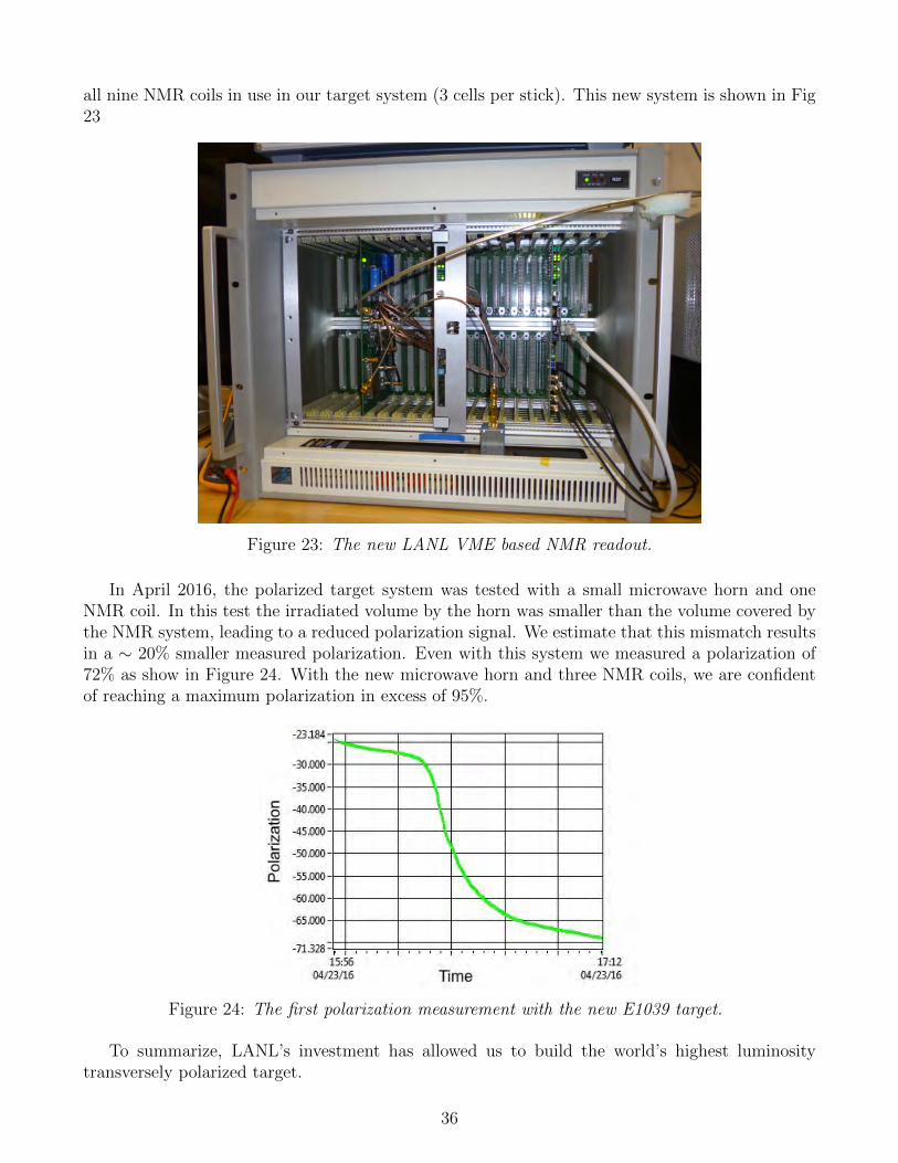
all nine NMR coils in use in our target system (3 cells per stick). This new system is shown in Fig23
Figure 23: The new LANL VME based NMR readout.
In April 2016, the polarized target system was tested with a small microwave horn and oneNMR coil. In this test the irradiated volume by the horn was smaller than the volume covered bythe NMR system, leading to a reduced polarization signal. We estimate that this mismatch resultsin a ∼ 20% smaller measured polarization. Even with this system we measured a polarization of72% as show in Figure 24. With the new microwave horn and three NMR coils, we are confidentof reaching a maximum polarization in excess of 95%.
Figure 24: The first polarization measurement with the new E1039 target.
To summarize, LANL’s investment has allowed us to build the world’s highest luminositytransversely polarized target.
36
B.2 Theoretical
Extracting the spin structure of the nucleon from the measurements of the quark Sivers asym-metry requires self-consistent and detailed theoretical interpretation of the results from Drell-Yanexperiment and from semi-inclusive deep inelastic lepton-proton scattering. The LDRD DR grantallowed us to initiate an integrated theory effort with three complementary components – pertur-bative QCD calculations, Soft Collinear Effective theory, and lattice gauge QCD. The ultimategoal is a much-improved description of the dynamic internal landscape of the nucleon from mea-surements of the Sivers asymmetry. The perturbative QCD effort has resulted in next-to-leadingorder calculations of the Sievers asymmetry in SIDIS and Drell-Yan and an extraction of the Siversfunction with next-to-leading logarithmic accuracy. Model calculations of quasi-parton distribu-tion functions were also performed. The Soft Collinear Effective Theory effort has demonstratedthe equivalence of the pQCD and SCET resummation approaches and calculated two-loop softfunctions for use in a variety of processes. Lattice QCD has produced new results for the momentsof the Sivers asymmetry from connected diagrams and compared to results from global fitting.A new method for the evaluation of disconnected diagrams has also been investigated. The inte-grated theory model, with its pQCD, SCET and LQCD components, was the stepping stone forthe formation of the TMD Topical Collaboration in nuclear theory.
B.3 LANL reviews
During the course of the LDRD project the LDRD office required two reviews of the physics,technical efforts and progress both in the experimental as well as the theoretical aspects of theLDRD project. The review panels included external as well as internal members of the community.The first review committee was composed of: C. Keith, Jefferson Lab, S. Kuhn, Old DominionUniversity and J. Qiu, Brookhaven National Laborartory as external members and C. Olinger,M. Brooks and B. Louis from LANL as internal. The second committee consisted of G. Dodge,Old Dominion University, and L. Gamberg, Penn State University as well as A. Hayes-Sterbenzand M. Brooks from LANL. In both reviews the physics program as well as the experimental andtheoretical have been consistently been deemed as outstanding. In the following we show excerptsfrom the two reviews:
Review Jan 2015Quality : Outstanding The quark and gluon Sivers functions of a polarized proton describethe quantum correlations between its spin and the direction as well as the strength of confinedorbital motion of quarks and gluons within it. They encode critical information on the confinedstructure and motion of quarks and gluons making up the proton’s properties, such as the spin,and are fundamental properties of QCD dynamics. The predicted sign change of the Sivers func-tions measured in Semi-inclusive DIS to that measured in Drell-Yan processes is deeply rooted inthe gauge property of QCD and the validity of QCD factorization. Owing to the color confine-ment - the defining property of QCD, meaning that we can’t probe the proton’s partonic structurewithout QCD factorization - developing the formalism to precisely connect the QCD dynamics tothe measured cross sections of leptons and hadrons is an area of active research. The predictedsign change of Sivers functions has been recognized as the most important test of and challenge toour understanding of QCD dynamics. It attracted tremendous theoretical and experimental effortworldwide to find a way to confirm or disapprove this prediction. The Sivers functions have been
37
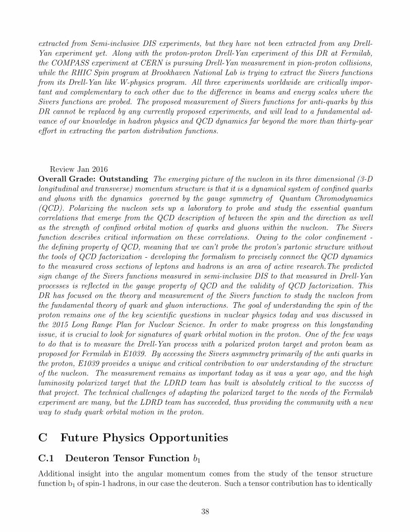
extracted from Semi-inclusive DIS experiments, but they have not been extracted from any Drell-Yan experiment yet. Along with the proton-proton Drell-Yan experiment of this DR at Fermilab,the COMPASS experiment at CERN is pursuing Drell-Yan measurement in pion-proton collisions,while the RHIC Spin program at Brookhaven National Lab is trying to extract the Sivers functionsfrom its Drell-Yan like W-physics program. All three experiments worldwide are critically impor-tant and complementary to each other due to the difference in beams and energy scales where theSivers functions are probed. The proposed measurement of Sivers functions for anti-quarks by thisDR cannot be replaced by any currently proposed experiments, and will lead to a fundamental ad-vance of our knowledge in hadron physics and QCD dynamics far beyond the more than thirty-yeareffort in extracting the parton distribution functions.
Review Jan 2016Overall Grade: Outstanding The emerging picture of the nucleon in its three dimensional (3-Dlongitudinal and transverse) momentum structure is that it is a dynamical system of confined quarksand gluons with the dynamics governed by the gauge symmetry of Quantum Chromodynamics(QCD). Polarizing the nucleon sets up a laboratory to probe and study the essential quantumcorrelations that emerge from the QCD description of between the spin and the direction as wellas the strength of confined orbital motion of quarks and gluons within the nucleon. The Siversfunction describes critical information on these correlations. Owing to the color confinement -the defining property of QCD, meaning that we can’t probe the proton’s partonic structure withoutthe tools of QCD factorization - developing the formalism to precisely connect the QCD dynamicsto the measured cross sections of leptons and hadrons is an area of active research.The predictedsign change of the Sivers functions measured in semi-inclusive DIS to that measured in Drell-Yanprocesses is reflected in the gauge property of QCD and the validity of QCD factorization. ThisDR has focused on the theory and measurement of the Sivers function to study the nucleon fromthe fundamental theory of quark and gluon interactions. The goal of understanding the spin of theproton remains one of the key scientific questions in nuclear physics today and was discussed inthe 2015 Long Range Plan for Nuclear Science. In order to make progress on this longstandingissue, it is crucial to look for signatures of quark orbital motion in the proton. One of the few waysto do that is to measure the Drell-Yan process with a polarized proton target and proton beam asproposed for Fermilab in E1039. By accessing the Sivers asymmetry primarily of the anti quarks inthe proton, E1039 provides a unique and critical contribution to our understanding of the structureof the nucleon. The measurement remains as important today as it was a year ago, and the highluminosity polarized target that the LDRD team has built is absolutely critical to the success ofthat project. The technical challenges of adapting the polarized target to the needs of the Fermilabexperiment are many, but the LDRD team has succeeded, thus providing the community with a newway to study quark orbital motion in the proton.
C Future Physics Opportunities
C.1 Deuteron Tensor Function b1
Additional insight into the angular momentum comes from the study of the tensor structurefunction b1 of spin-1 hadrons, in our case the deuteron. Such a tensor contribution has to identically
38
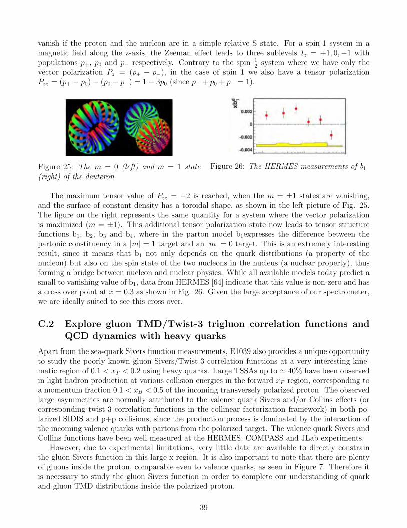
vanish if the proton and the nucleon are in a simple relative S state. For a spin-1 system in amagnetic field along the z-axis, the Zeeman effect leads to three sublevels Iz = +1, 0,−1 withpopulations p+, p0 and p− respectively. Contrary to the spin 1
2system where we have only the
vector polarization Pz = (p+ − p−), in the case of spin 1 we also have a tensor polarizationPzz = (p+ − p0)− (p0 − p−) = 1− 3p0 (since p+ + p0 + p− = 1).
Figure 25: The m = 0 (left) and m = 1 state(right) of the deuteron
Figure 26: The HERMES measurements of b1
The maximum tensor value of Pzz = −2 is reached, when the m = ±1 states are vanishing,and the surface of constant density has a toroidal shape, as shown in the left picture of Fig. 25.The figure on the right represents the same quantity for a system where the vector polarizationis maximized (m = ±1). This additional tensor polarization state now leads to tensor structurefunctions b1, b2, b3 and b4, where in the parton model b1expresses the difference between thepartonic constituency in a |m| = 1 target and an |m| = 0 target. This is an extremely interestingresult, since it means that b1 not only depends on the quark distributions (a property of thenucleon) but also on the spin state of the two nucleons in the nucleus (a nuclear property), thusforming a bridge between nucleon and nuclear physics. While all available models today predict asmall to vanishing value of b1, data from HERMES [64] indicate that this value is non-zero and hasa cross over point at x = 0.3 as shown in Fig. 26. Given the large acceptance of our spectrometer,we are ideally suited to see this cross over.
C.2 Explore gluon TMD/Twist-3 trigluon correlation functions andQCD dynamics with heavy quarks
Apart from the sea-quark Sivers function measurements, E1039 also provides a unique opportunityto study the poorly known gluon Sivers/Twist-3 correlation functions at a very interesting kine-matic region of 0.1 < xT < 0.2 using heavy quarks. Large TSSAs up to ' 40% have been observedin light hadron production at various collision energies in the forward xF region, corresponding toa momentum fraction 0.1 < xB < 0.5 of the incoming transversely polarized proton. The observedlarge asymmetries are normally attributed to the valence quark Sivers and/or Collins effects (orcorresponding twist-3 correlation functions in the collinear factorization framework) in both po-larized SIDIS and p+p collisions, since the production process is dominated by the interaction ofthe incoming valence quarks with partons from the polarized target. The valence quark Sivers andCollins functions have been well measured at the HERMES, COMPASS and JLab experiments.
However, due to experimental limitations, very little data are available to directly constrainthe gluon Sivers function in this large-x region. It is also important to note that there are plentyof gluons inside the proton, comparable even to valence quarks, as seen in Figure 7. Therefore itis necessary to study the gluon Sivers function in order to complete our understanding of quarkand gluon TMD distributions inside the polarized proton.
39
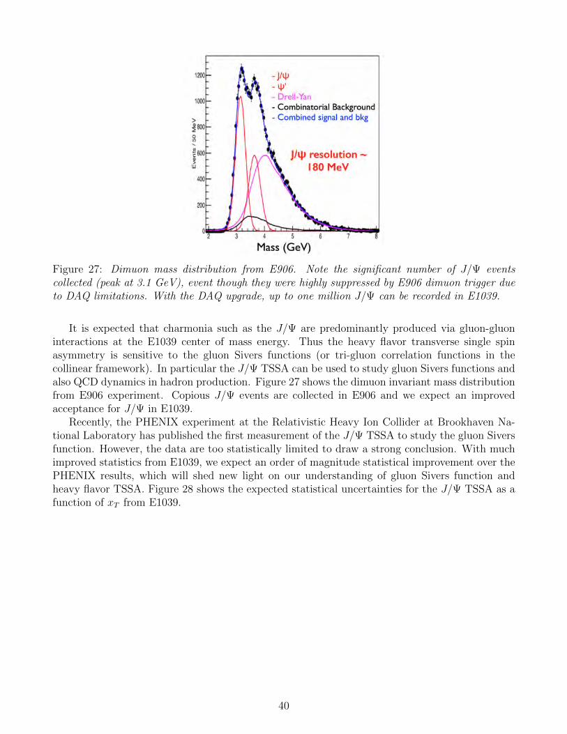
Figure 27: Dimuon mass distribution from E906. Note the significant number of J/Ψ eventscollected (peak at 3.1 GeV), event though they were highly suppressed by E906 dimuon trigger dueto DAQ limitations. With the DAQ upgrade, up to one million J/Ψ can be recorded in E1039.
It is expected that charmonia such as the J/Ψ are predominantly produced via gluon-gluoninteractions at the E1039 center of mass energy. Thus the heavy flavor transverse single spinasymmetry is sensitive to the gluon Sivers functions (or tri-gluon correlation functions in thecollinear framework). In particular the J/Ψ TSSA can be used to study gluon Sivers functions andalso QCD dynamics in hadron production. Figure 27 shows the dimuon invariant mass distributionfrom E906 experiment. Copious J/Ψ events are collected in E906 and we expect an improvedacceptance for J/Ψ in E1039.
Recently, the PHENIX experiment at the Relativistic Heavy Ion Collider at Brookhaven Na-tional Laboratory has published the first measurement of the J/Ψ TSSA to study the gluon Siversfunction. However, the data are too statistically limited to draw a strong conclusion. With muchimproved statistics from E1039, we expect an order of magnitude statistical improvement over thePHENIX results, which will shed new light on our understanding of gluon Sivers function andheavy flavor TSSA. Figure 28 shows the expected statistical uncertainties for the J/Ψ TSSA as afunction of xT from E1039.
40
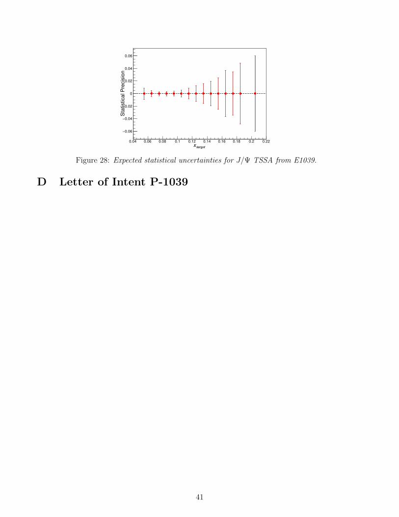
targetx
0.04 0.06 0.08 0.1 0.12 0.14 0.16 0.18 0.2 0.22
Sta
tistical P
recis
ion
0.06−
0.04−
0.02−
0
0.02
0.04
0.06
GraphGraph
Figure 28: Expected statistical uncertainties for J/Ψ TSSA from E1039.
D Letter of Intent P-1039
41
Letter of Intent for a Drell-‐Yan experim
ent with a polarized proton
target Co-‐Spokespersons: A. K
lein, X. Jiang, Los Alamos N
ational Laboratory List of Collaborators:
D. G
eesaman, P. R
eimer
Argonne National Laboratory, Argonne, IL 60439
C. B
rown , D
. Christian
Fermi N
ational Accelerator Laboratory, Batavia IL 60510 M
. Diefenthaler, J.-C
. Peng U
niversity of Illinois, Urbana, IL 61081
W.-C
. Chang, Y
.-C. C
hen Institute of Physics, Academ
ia Sinica, Taiwan
S. Sawada
KEK
, Tsukuba, Ibaraki 305-0801, Japan T. -H
. Chang
Ling-Tung University, Taiw
an J. H
uang, X. Jiang, M
. Leitch, A. K
lein, K. Liu, M
. Liu, P. McG
aughey Los Alam
os National Laboratory, Los Alam
os, NM
87545 E. B
eise, K. N
akahara U
niversity of Maryland, C
ollege Park, MD
20742 C
. Aidala, W
. Lorenzon, R. R
aymond
University of M
ichigan, Ann Arbor, MI 48109-1040
T. Badm
an, E. Long, K. Slifer, R
. Zielinski U
niversity of New
Ham
pshire, Durham
, NH
03824 R
.-S. Guo
National K
aohsiung Norm
al University, Taiw
an Y
. Goto
RIKEN
, Wako, Saitam
a 351-01, Japan L. El Fassi, K. M
yers, R. Ransome, A. Tadepalli, B. Tice
Rutgers University, Rutgers N
J 08544 J. -P. C
hen Thom
as Jefferson National Accelerator Facility, N
ewport N
ews, VA 23606
K. N
akano, T.-A. Shibata
Tokyo Institute of Technology, Tokyo 152-8551, Japan D
. Crabb, D
. Day, D
. Keller, O
. Rondon
University of Virginia, C
harlottesville, VA 22904
1. Physics motivation
It is well know
n that the proton is a spin-1/2 particle, but how the constituents (quarks and
gluons) assemble to this quantized spin is still a m
ystery. There is a worldw
ide effort to map out
the individual contributions to the proton spin [1,2]. It is established that the quark spins contribute around 30%
, while the gluon intrinsic angular m
omentum
is still under active investigation at the R
elativistic Heavy Ion C
ollider [3]. Fully resolving the proton spin puzzle requires inform
ation on the orbital angular mom
entum (O
AM
) of both quarks and gluons. Recent
studies have shown that the so-called transverse m
omentum
dependent parton distribution functions (TM
Ds) can inform
us about the OA
M of the partons.
One of the m
ost important TM
Ds, and the m
ain focus of this LOI, is the so-called Sivers
function [4]. It was introduced in 1990 to help explain the large transverse single-spin
asymm
etries observed in hadronic pion production at Fermilab [5]. The quark Sivers function
represents the mom
entum distribution of unpolarized quarks inside a transversely polarized
proton, through a correlation between the quark m
omentum
transverse to the beam and the
proton spin. On one hand, the Sivers function contains inform
ation on both the longitudinal and transverse m
otion of the partons and provides a unique way to perform
3-dimensional proton
tomography in m
omentum
space [1, 2]. On the other hand, it has been show
n that there is a close connection betw
een the Sivers function and quark OA
M. Though the search for a rigorous,
model-independent connection is still ongoing, it is clear that the existence of a non-zero Sivers
function requires non-zero quark OA
M [1]. From
a detailed analysis of the azimuthal distribution
of the produced particles from a transversely polarized nucleon, one can deduce properties of the
nucleon structure. This approach has been used in Sem
i-Inclusive Deep Inelastic Scattering (SID
IS) experiments,
where non-zero values of the Sivers function from
HER
MES [6], C
OM
PASS [7] and JLab [8]
have indicated that the orbital angular mom
entum of the up quarks is positive (L
u > 0) but of the dow
n quarks is negative (Ld < 0.) The anti-dow
n versus anti-up quark excess in the proton observed in D
rell-Yan (D
Y) m
easurements by E866 [Figure 1], w
hen interpreted in the pion cloud m
odel, provides a strong hint that the sea quarks contribute significantly to the orbital angular m
omentum
[9], in the x range where significant valence quark Sivers asym
metries w
ere observed in SID
IS. How
ever, current SIDIS experim
ents have little sensitivity to the antiquark Sivers asym
metry in this kinem
atic range. Thus, a direct measurem
ent of the Sivers function for the antiquarks has becom
e crucial and can only be accessed cleanly via the Drell-Y
an process. W
e propose to carry out the first measurem
ent of the sea quark Sivers function, using Drell-Y
an production from
an unpolarized 120 GeV
proton beam scattering off a transversely polarized
proton target. B
esides helping to resolve the proton spin puzzle, this proposal helps address the recent NSA
C
milestone H
P13 to “test unique QC
D predictions for relations betw
een single transverse spin phenom
ena in p-p scattering and those observed in deep inelastic lepton scattering.” A
fundamental prediction of Q
CD
is that the Sivers function changes sign, when going from
SIDIS
to DY
production [10]. This prediction is deeply rooted in the gauge structure of QC
D as a field
theory, and is based on the well-know
n QC
D factorization form
alism w
idely used in interpreting high-energy experim
ental data. Thus, its experimental verification or refutation is crucial. The
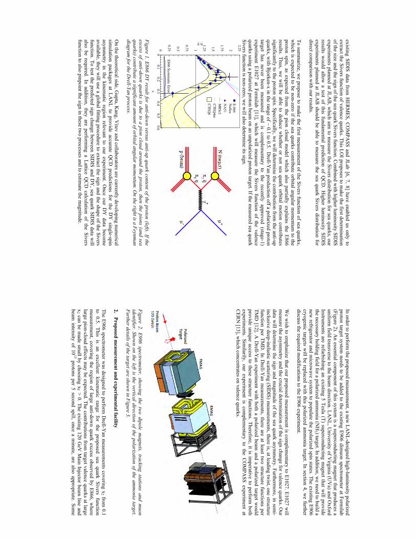
existing SIDIS data from
HER
MES, C
OM
PASS and JLab [6, 7, 8] have enabled us only to
extract the Sivers function of valence quarks. This LOI proposes to m
ake the first determination
of the size and the sign of the sea quark Sivers function. Com
bined with higher lum
inosity SIDIS
experiments planned at JLA
B, w
hich aim to m
easure the Sivers distribution for sea quarks, our results w
ould allow a test of this fundam
ental prediction of QC
D. H
igher luminosity SID
IS experim
ents planned at JLAB
should be able to measure the sea quark Sivers distribution for
direct comparison w
ith our results. To sum
marize, w
e propose to make the first m
easurement of the Sivers function of sea quarks,
which is expected to be non-zero if the sea quarks contribute orbital angular m
omentum
to the proton spin, as expected from
the pion cloud model w
hich also partially explains the E866 results. Thus, w
e will be able to deduce w
hether or not sea quark orbital motion contributes
significantly to the proton spin. Specifically, we w
ill determine the contribution from
the anti-up quarks, w
ith Bjorken-x in the range of ~ 0.1 to 0.5. D
rell-Yan production off a polarized proton
target has never been measured and is com
plementary to the recently approved (stage-1)
experiment E1027 at Ferm
ilab [11], which w
ill measure the Sivers function of the valence
quarks using a polarized proton beam on an unpolarized proton target. If the m
easured sea quark Sivers function is non-zero, w
e will also determ
ine its sign.
Figure 1. E866 D
Y result for anti-down versus anti-up quark content of the proton (left). If the
excess of anti-down quarks is due to a pion cloud around the proton, then the pions (and sea
quarks) contribute a significant amount of orbital angular m
omentum
. On the right is a Feynm
an diagram
for the Drell-Yan process.
On the theoretical side, G
upta, Kang, V
itev and collaborators are currently developing numerical
simulation packages at LA
NL to provide accurate Q
CD
predictions for the DY
single-spin asym
metry in the kinem
atic region relevant to our experiment. O
nce our DY
data become
available, they will use a global fitting procedure to extract the sign and the shape of the Sivers
function. To test the predicted sign change between SID
IS and DY
, sea quark SIDIS data w
ill also be required. In addition, they are perform
ing a Lattice QC
D calculation of the Sivers
function to also pinpoint the sign in these two processes and to estim
ate the magnitude.
0
0.2
5
0.5
0.7
5 1
1.2
5
1.5
1.7
5 2
2.2
5
00
.10
.20
.30
.40
.50
.6
x
d- /u
-
E8
66
Sy
stematic E
rror
E-8
66
Nu
Sea
NA
51
MR
Sr2
CT
EQ
4m
CT
EQ
6
In order to perform the proposed m
easurement, a new
LAN
L-designed high-luminosity polarized
proton target system needs to be added to the existing E906 dim
uon spectrometer at Ferm
ilab (Figure 2). A
n essential component of this system
is a superconducting magnet that produces a
uniform field transverse to the beam
direction. LAN
L, University of V
irginia (UV
a) and Oxford
Instruments are refurbishing an existing 5 Tesla (T) superconducting m
agnet that will provide
the necessary holding field for a polarized amm
onia (NH
3 ) target. In addition, we need to build a
new refrigerator and m
icrowave system
to populate the polarized spin states. The existing E906 cryogenic targets w
ill be replaced with this polarized am
monia target. In section 4, w
e further discuss the required m
odifications to the E906 experiment.
We w
ish to emphasize that our proposed m
easurement is com
plementary to E1027. E1027 w
ill m
easure the asymm
etry and the crucial determination of the sign change for valence quarks. O
ur data w
ill determine the sign and m
agnitude of the sea quark asymm
etry. Furthermore, in sem
i-inclusive deep-inelastic scattering (SID
IS) measurem
ents, there is, at leading twist, one structure
function per TMD
. In Drell-Y
an measurem
ents, there are at least two structure functions per
TMD
[12]. A D
rell-Yan experim
ent with both a polarized beam
and a polarized target would
provide unique access to these structure functions. Therefore, it is imperative to perform
both experim
ents. Similarily, our experim
ent is complem
entary to the CO
MPA
SS experiment at
CER
N [13], w
hich concentrates on valence quarks.
Figure 2. E906 spectrom
eter, showing the tw
o dipole magnets, tracking stations and m
uon identifier. Show
n on the left is the vertical direction of the polarization of the amm
onia target. Further details of the target are show
n in Figure 3. 2.
Proposed measurem
ent and experimental facility
The E906 spectrometer w
as designed to perform D
rell-Yan m
easurements covering x
2 from 0.1
to 0.5. This is an excellent kinematic range for the proposed sea quark Sivers function
measurem
ent, covering the region of large anti-down quark excess observed by E866, w
here large pion-cloud effects m
ay be expected. The contributions from target valence quarks at large
x2 can be m
ade small by choosing x
F > 0. The existing 120 GeV
Main Injector beam
line and beam
intensity of 1013 protons per 5 second spill, once a m
inute, are also appropriate. Some
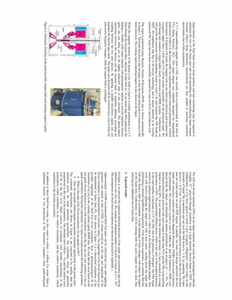
improvem
ents to the final beam focus, beam
position and halo monitoring m
ay be required to m
inimize the size of the beam
spot and avoid quenching the superconducting target magnet.
Accurate relative beam
luminosity m
easurements are also needed to m
inimize system
atic uncertainties due to false asym
metries.
A 5 T superconducting m
agnet from LA
NL has recently been re-com
missioned at full field at
UV
a during February, 2013. This target magnet w
as originally designed for longitudinal polarization (relative to the beam
) while our experim
ent requires transverse polarization. Oxford
Instruments of England w
ill rotate the magnet coils to the transverse direction and reconnect the
cryogenic supply lines. LAN
L and UV
a will be jointly responsible for the polarized target. W
e w
ill design and construct a target ladder insert, microw
ave and NM
R system
s. Furthermore, w
e w
ill provide the necessary helium pum
ping system to reach 1 K
, and irradiate the NH
3 beads at N
IST. We em
phasize that this is all proven technology and is almost identical to an existing
polarized NH
3 target that has been successfully operated for years at SLAC
and Jefferson Lab. The target is polarized using D
ynamic N
uclear Polarization (DN
P) and is shown schem
atically in Figure 3. The beam
direction is into the page, so that the target polarization is transverse to the beam
direction. The existing superconducting magnet is also show
n in the figure. W
hile the magnetic m
oment of the proton is too sm
all to lead to a sizable polarization in a 5 T field through the Zeem
an effect, electrons in that field at 1 K are better than 99%
polarized. By
doping a suitable solid target material w
ith paramagnetic radicals to provide unpaired electron
spins, one can make use of the highly polarized state of the electrons. The dipole-dipole
interaction between the nucleon and the electron leads to hyperfine splitting, providing the
coupling between the tw
o spin species. By applying a suitable m
icrowave signal, one can
populate the desired spin states. The target spin direction will be reversed once every 8 hours by
microw
ave frequency changes, while the m
agnet field is unchanged.
Figure 3. Schem
atic drawing of the polarized N
H3 target (left) and existing m
agnet (right).
We w
ill use frozen amm
onia (NH
3) as the target material and create the param
agnetic radicals (roughly 10
19 spins/ml) through irradiation w
ith a high intensity electron beam at N
IST. Our
collaborators at UV
a have agreed to build a new cryogenic refrigerator, w
hich works on the
principle of liquid 4He evaporation and can cool the bath dow
n to ~1 K, by pum
ping 4He vapor
down to < 0.18 Torr. U
Va scientists have built m
any polarized systems over the last tw
o decades and are w
orld experts on such DN
P targets. In parallel, our team w
ill design and build the new
target cell, microw
ave system and N
uclear Magnetic R
esonance (NM
R) system
used to measure
the polarization. The microw
ave system is used to induce the spin flip transition. N
MR
coils, placed inside the target, can determ
ine the proton polarization to an accuracy of ~ +/- 4%. The
maxim
um polarization achieved w
ith such a target is better than 92% and the N
H3 bead packing
fraction is about 60%. In our estim
ate for the statistical precision, we have assum
ed an average polarization of 80%
. The polarization dilution factor, which is the ratio of free polarized protons
to the total number of nucleons, is 3/17 for N
H3 , due to the presence of nitrogen. The N
H3 beads
need to be replaced approximately every 5 days, due to the beam
induced radiation damage. This
work w
ill involve replacing the target stick with a new
insert, cooling down the target and
performing a therm
al equilibrium m
easurement. From
previous experience, we estim
ate that this w
ill take about a shift to accomplish. C
areful planning of these changes will reduce the im
pact on the beam
time. Furtherm
ore, we w
ill be running with tw
o active targets on one stick, thus reducing any additional loss of beam
time.
3. E
xpected results In Figure 4, w
e present the expected statistical precision of the single spin asymm
etry that can be obtained in a one year run. W
e assume an integrated num
ber of protons on target of 2.7 x 10¹⁸.
The assumptions on w
hich these calculations are based are discussed in Appendix 1.
Approxim
ately 110,000 reconstructed Drell-Y
an pairs can be collected per year, after applying geom
etry cuts similar to that of E906. A
strong sensitivity to the sign and magnitude of the
Sivers asymm
etry is demonstrated for non-zero values. The m
agnitude of the Sivers function can be determ
ined to better than 4%. A
lso shown in Figure 4 is a theoretical estim
ation of the possible m
agnitude of the Drell-Y
an Sivers asymm
etry from a phenom
enological fit by A
nselmino et al [14] to the existing valence quark SID
IS data. We note that the error band on the
sea quark Sivers function is not well constrained, since the fits are not very sensitive to the sea
quark contribution. During this experim
ent, we expect to clearly answ
er the following questions:
• W
hat is the sign of the Sivers asymm
etry for sea quarks in DY
? •
Does the sea quark orbital angular m
omentum
contribute significantly to the proton spin? The system
atic uncertainties, not shown in Figure 4, are expected to be sm
aller than the statistical
errors, for
small
measured
asymm
etries. The
systematic
errors are
generally proportional to the size of the asym
metry. The absolute error w
ill be ~ 1% and the relative error
will be at the 4%
level. Major sources of system
atic error include uncertainties in the polarization, w
hich contributes to the relative uncertainty, and the relative luminosity, w
hich contributes to the absolute uncertainty. In addition to these D
rell-Yan events, w
e also expect to collect ~1 million J/ψ events. Since a
substantial fraction of J/ψ production at this kinematics originates from
quark-antiquark
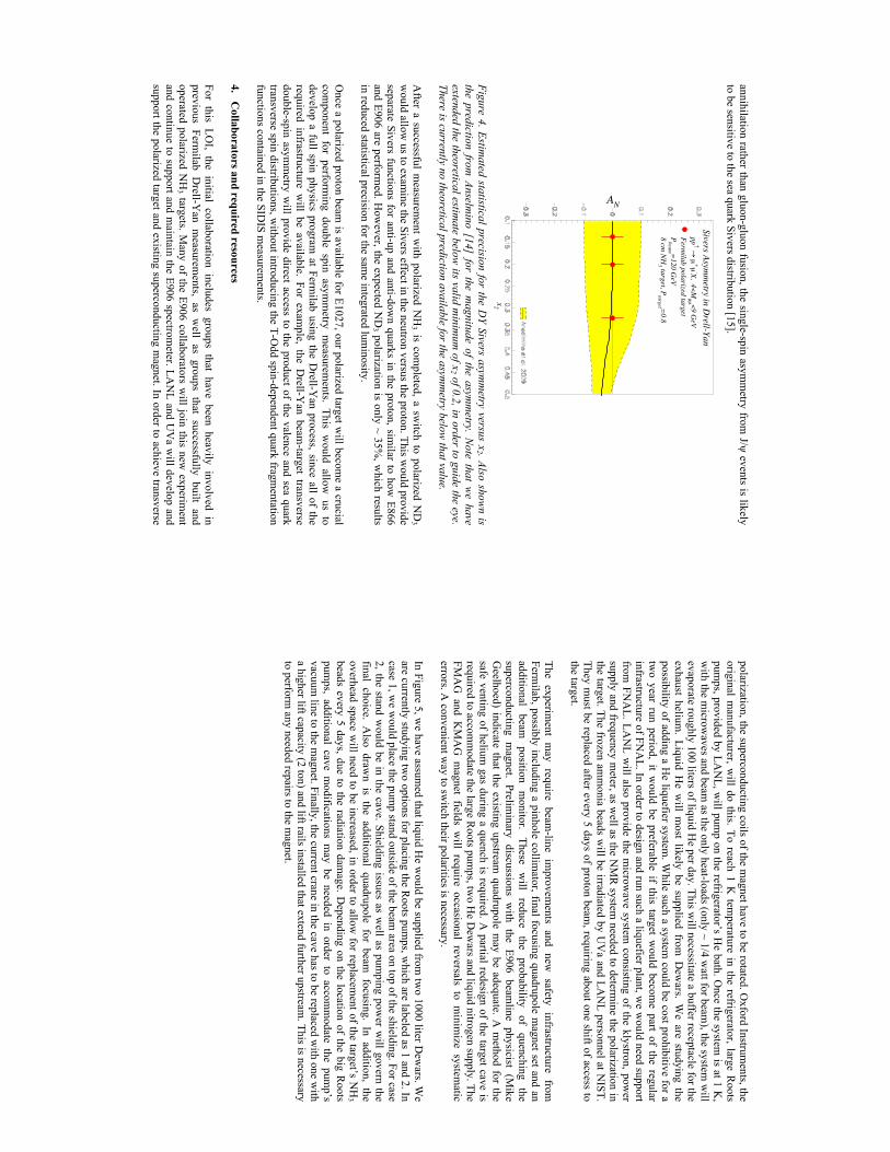
annihilation rather than gluon-gluon fusion, the single-spin asymm
etry from J/ψ events is likely
to be sensitive to the sea quark Sivers distribution [15].
Figure 4. Estim
ated statistical precision for the DY Sivers asym
metry versus x
2 . Also shown is
the prediction from Anselm
ino [14] for the magnitude of the asym
metry. N
ote that we have
extended the theoretical estimate below
its valid minim
um of x
2 of 0.2, in order to guide the eye. There is currently no theoretical prediction available for the asym
metry below
that value. A
fter a successful measurem
ent with polarized N
H3 is com
pleted, a switch to polarized N
D3
would allow
us to examine the Sivers effect in the neutron versus the proton. This w
ould provide separate Sivers functions for anti-up and anti-dow
n quarks in the proton, similar to how
E866 and E906 are perform
ed. How
ever, the expected ND
3 polarization is only ~ 35%, w
hich results in reduced statistical precision for the sam
e integrated luminosity.
Once a polarized proton beam
is available for E1027, our polarized target will becom
e a crucial com
ponent for performing double spin asym
metry m
easurements. This w
ould allow us to
develop a full spin physics program at Ferm
ilab using the Drell-Y
an process, since all of the required infrastructure w
ill be available. For example, the D
rell-Yan beam
-target transverse double-spin asym
metry w
ill provide direct access to the product of the valence and sea quark transverse spin distributions, w
ithout introducing the T-Odd spin-dependent quark fragm
entation functions contained in the SID
IS measurem
ents. 4.
Collaborators and required resources
For this LOI, the initial collaboration includes groups that have been heavily involved in
previous Fermilab D
rell-Yan m
easurements, as w
ell as groups that successfully built and operated polarized N
H3 targets. M
any of the E906 collaborators will join this new
experiment
and continue to support and maintain the E906 spectrom
eter. LAN
L and UV
a will develop and
support the polarized target and existing superconducting magnet. In order to achieve transverse
x2
Sivers Asymm
etry in Drell-Yan
ppB A
µ+µ
-X, 4<Mµµ <9 G
eVFerm
ilab polarized targetP
beam =120 G
eV8 cm
NH
3 target, Ptarget =
0.8
AN
polarization, the superconducting coils of the magnet have to be rotated. O
xford Instruments, the
original manufacturer, w
ill do this. To reach 1 K tem
perature in the refrigerator, large Roots
pumps, provided by LA
NL, w
ill pump on the refrigerator’s H
e bath. Once the system
is at 1 K,
with the m
icrowaves and beam
as the only heat-loads (only ~ 1/4 watt for beam
), the system w
ill evaporate roughly 100 liters of liquid H
e per day. This will necessitate a buffer receptacle for the
exhaust helium. Liquid H
e will m
ost likely be supplied from D
ewars. W
e are studying the possibility of adding a H
e liquefier system. W
hile such a system could be cost prohibitive for a
two year run period, it w
ould be preferable if this target would becom
e part of the regular infrastructure of FN
AL. In order to design and run such a liquefier plant, w
e would need support
from FN
AL. LA
NL w
ill also provide the microw
ave system consisting of the klystron, pow
er supply and frequency m
eter, as well as the N
MR
system needed to determ
ine the polarization in the target. The frozen am
monia beads w
ill be irradiated by UV
a and LAN
L personnel at NIST.
They must be replaced after every 5 days of proton beam
, requiring about one shift of access to the target. The experim
ent may require beam
-line improvem
ents and new safety infrastructure from
Ferm
ilab, possibly including a pinhole collimator, final focusing quadrupole m
agnet set and an additional
beam
position m
onitor. These
will
reduce the
probability of
quenching the
superconducting magnet. Prelim
inary discussions with the E906 beam
line physicist (Mike
Geelhoed) indicate that the existing upstream
quadrupole may be adequate. A
method for the
safe venting of helium gas during a quench is required. A
partial redesign of the target cave is required to accom
modate the large R
oots pumps, tw
o He D
ewars and liquid nitrogen supply. The
FMA
G and K
MA
G m
agnet fields will require occasional reversals to m
inimize system
atic errors. A
convenient way to sw
itch their polarities is necessary. In Figure 5, w
e have assumed that liquid H
e would be supplied from
two 1000 liter D
ewars. W
e are currently studying tw
o options for placing the Roots pum
ps, which are labeled as 1 and 2. In
case 1, we w
ould place the pump stand outside of the beam
area on top of the shielding. For case 2, the stand w
ould be in the cave. Shielding issues as well as pum
ping power w
ill govern the final choice. A
lso drawn is the additional quadrupole for beam
focusing. In addition, the overhead space w
ill need to be increased, in order to allow for replacem
ent of the target’s NH
3 beads every 5 days, due to the radiation dam
age. Depending on the location of the big R
oots pum
ps, additional cave modifications m
ay be needed in order to accomm
odate the pump’s
vacuum line to the m
agnet. Finally, the current crane in the cave has to be replaced with one w
ith a higher lift capacity (2 ton) and lift rails installed that extend further upstream
. This is necessary to perform
any needed repairs to the magnet.
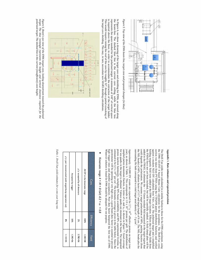
Figure 5. Top view
of the E906 beam-‐line, target cave and proposed changes (in blue).
In Figure 6, we show
a drawing of the target cave and shielding for E906, as view
ed along the beam
-‐line. The dashed blue line is the current cave ceiling, while the blue box
represents the space needed for the polarized target. A minim
um of 140” of vertical space
is required above the floor, in order to accommodate the extraction of the target ladder.
This would require raising the roof of the cave by roughly 32”, through a partial restacking of
the target cave shielding. This may , in turn, necessitate new
MA
RS shielding calculations.
Figure 6. Beam’s eye view
of the E906 target cave, looking downstream
toward the polarized
target. The blue rectangle represents the height and vertical clearance required for the polarized target. The dashed line is the current (insufficient) cave height.
Appendix 1. R
ate estimates and expected precision
The Drell-Y
an yields were calculated in a sim
ilar fashion to those for the E906 experiment, using
the E906 GEA
NT 4 based M
onte Carlo calculation for the acceptance. The D
rell-Yan cross
section was taken from
PYTH
IA using the C
TEQ5M
parton distribution functions and verified against a m
odern NLO
DY
calculation from V
itev, et.al. The polarized target and a simplified
holding magnetic field w
ere added at the E906 target location. Effects due to fringe fields from
the FMA
G have not yet been included, but w
ill be carefully studied. A field clam
p plate will be
added to the FMA
G, to elim
inate the ~ 15 Gauss residual field m
easured in the target region that could degrade the polarization. W
e assume a target polarization of 80%
, packing fraction (from
the NH
3 beads) of 60%, dilution factor of 3/17 and target length of 8 cm
. The NH
3 beads plus the surrounding H
e bath correspond to a total target areal density of ~ 5 g/cm2.
Approxim
ately 110,000 DY
events are expected for 2.7 x 10¹⁸ effective protons on target (one
year), as shown in Table 1. This corresponds to 1.0 x 10
13 protons per spill. The distribution of sam
pled parton mom
entum fraction, in term
s of x1 and x
2 , is shown in Figure 7. G
ood coverage for sea quarks in the target is obtained. V
alence quarks are dominant in the beam
. The integrated proton–nucleon lum
inosity, including 50% beam
availability and 80% experim
ental livetime, is
estimated to be 6.5 x 10
42 per cm2. The kinem
atic coverage is given in the table below. Since the
spectrometer w
ill be operating at very high rates, a good beam duty factor is essential to prevent
high trigger rates and chamber occupancies. Poor duty factor ham
pered the first run of E906. W
hatever solution is found for E906 should be adequate for our purpose.
Table 1. D
rell-Yan yield estimates for a one-year long run.
Estimated yield
•Total integrated lum
inosity (one year): 1.40!1043 cm
-2
•A
ccelerator efficiency: 50%
•Spectrom
eter efficiency: 80%
•K
inematic range: 4 < M
< 8 GeV, -0.2 < x
F < 0.8
Cuts
EfficiencyYield
All D
Y in the kinematic range
100%1.34E+08
µ+µ
- accepted by all detectors2%
2.78E+06
Accepted by trigger
50%1.39E+06
µ+µ
- pair reconstructed (with target/dum
p separation cut)8%
1.11E+05
Figure 7. Expected distribution of D
rell-Yan events, in terms of Bjorken-x
1 (beam) and x
2 (polarized target). The vertical axis is num
ber of events and error bars are statistical. References 1. D
. Boer, M
. Diehl, R
. Milner, R
. Venugopalan, W
. Vogelsang, D
. Kaplan, H
. Montgom
ery and S. V
igdor et al., “Gluons and the quark sea at high energies: D
istributions, polarization, tom
ography”, arXiv:1108.1713 [nucl-th].
2. A. A
ccardi, J. L. Albacete, M
. Anselm
ino, N. A
rmesto, E. C
. Aschenauer, A
. Bacchetta, D
. B
oer and W. B
rooks et al., “Electron Ion Collider: The N
ext QC
D Frontier - U
nderstanding the glue that binds us all”, arX
iv:1212.1701 [nucl-ex]. 3. E. A
schenauer, A. B
azilevsky, K. B
oyle, K. Eyser, R
. Fatemi, C
. Gagliardi, M
. Grosse-
Perdekamp, J. Lajoie and Z. B
. Kang et al., “The R
HIC
Spin Program: A
chievements and Future
Opportunities”, arX
iv:1304.0079 [nucl-ex]. 4. D
. Sivers, Phys. Rev. D
41 (1990) 83. 5. D
. L. Adam
s et al. [FNA
L-E704 Collaboration], Phys. Lett. B
264, 462 (1991). 6. A
. Airapetian et al. [H
ERM
ES Collaboration], Phys. R
ev. Lett. 103, 152002 (2009). 7. M
. Alekseev et al. [C
OM
PASS C
ollaboration], Phys. Lett. B 673, 127 (2009).
8. X. Q
ian et al. [JLab Hall A
Collaboration], Phys.R
ev.Lett.107:072003, 2011. 9. G
. Garvey, Phys. R
ev. C81 (2010) 055212 and E866 collaboration, Phys. R
ev. Lett. 80 (1998) 3715-3718. 10. J. C
. Collins, Phys. Lett. B
536, 43–48 (2002). 11. Ferm
ilab E1027 proposal, 2012. 12. S. A
rnold, A. M
etz, M. Schlegel, Phys.R
ev. D79 (2009) 034005.
13. CO
MPA
SS-II collaboration, http://ww
wcom
pass.cern.ch/compass/proposal/com
pass-II_proposal/ 14. M
. Anselm
ino, private comm
unication, based on M. A
nselmino et al. Eur. Phys. J. A
39, 89–100 (2009).
15. M
. Anselm
ino et al, Phys. Lett. B594 (2004) 97.
2x
00.1
0.2
0.3
0.4
0.5
Counts
4
10
5
10
1x
0.4
0.5
0.6
0.7
0.8
0.9
Counts
4
10
5
10

E Quote For Liquefier
48
uantum
Quantum
Technology Corp.
PM
B 183, 250 H Street Blaine W
A 98230 USA
Tel: +1-‐604-‐222-‐5539, Fax: +1-‐604-‐677-‐5826 Toll Free: +1-‐888 -‐271-‐9466 Fax: +1-‐888-‐711-‐5222
sales@quantum
-‐technology.com
http://www.quantum
-‐technology.com
To: M
r. Andi K
lein M
S-H846, G
roup P-25 LA
NL
Los Alam
os, NM
87545
office: A138, Bldg 1, TA
53
office: 505 667 8990 lab: 505 606 0662 em
ail: [email protected]
O
ffer Los Alam
os
Quotation #350703
July 5, 2015
Helium
Liquefaction + Purification system
Table of Contents
1. Price
2. Delivery Schedule
3. Point of Delivery
4. Payments Term
s
5. Sales and Use Taxes
6. Validity of the Q
uote
7. Appendices
uantum
Quantum
Technology Corp.
PM
B 183, 250 H Street Blaine W
A 98230 USA
Tel: +1-‐604-‐222-‐5539, Fax: +1-‐604-‐677-‐5826 Toll Free: +1-‐888 -‐271-‐9466 Fax: +1-‐888-‐711-‐5222
sales@quantum
-‐technology.com
http://www.quantum
-‐technology.com
1. Price
Customer Liquefier refurbishm
ent (estimation, pending on the actual state)…
.........
$30,000.00
RS Compression System
for liquefier ……
……
……
……
……
.……
...$149,000.00
Design of the w
hole system, valves and regulators (estim
ation)….…
….$30,000.00
RDT betw
een liquefier and dewar…
……
…...…
……
……
……
..……
...$12,000.00
Piping from liquefier to com
pressor……
……
……
……
……
……
……
.$12,500.00
Purifier for the entire flow…
……
……
……
……
……
...……
……
….....$65,000.00
Option for Purifier: Autom
ation (for purifier, see Appendix 1).......……
.$65,000.00
High pressure helium
recovery compressor…
……
...……
……
……
.….$27,500.00
Gas Bag including control for recovery com
pressor and relief valve…..$11,500.00
Com
missioning (price/day on site, expenses extra)…
……
….…
..……
…$1,500.00
Set of spare parts for purifier…
……
….…
..……
……
……
…..…
……
…$3,000.00
Set of spare parts for H
P compressor…
……
….…
..……
……
..……
……
$1,800.00
Warranty: 1 year parts and factory service
Note: Perform
ance Test and Manual are included
2. Delivery Schedule
Expected delivery date is 36 weeks from
date of the PO.
uantum
Quantum
Technology Corp.
PM
B 183, 250 H Street Blaine W
A 98230 USA
Tel: +1-‐604-‐222-‐5539, Fax: +1-‐604-‐677-‐5826 Toll Free: +1-‐888 -‐271-‐9466 Fax: +1-‐888-‐711-‐5222
sales@quantum
-‐technology.com
http://www.quantum
-‐technology.com
3. Point of delivery
Above prices are valid for point of fabrication, V
ancouver, Canada.
4. Payment Term
s
• 30%
of the contract value at the time of receiving the Purchase O
rder •
50% of the contract value at the beginning of the system
fabrication •
15% of the contract value after issuance of “N
otice of Completion”
• 5%
of the contract value after submission of the final docum
entation
5. Sales and Use Taxes
Above prices include value added, sales and/or use taxes in N
orth Am
erica, all customs, local taxes at the
customer site are the obligation of the custom
er.
6. Validity of the Q
uote
This quotation is valid for sixty (60) days.
uantum
Quantum
Technology Corp.
PM
B 183, 250 H Street Blaine W
A 98230 USA
Tel: +1-‐604-‐222-‐5539, Fax: +1-‐604-‐677-‐5826 Toll Free: +1-‐888 -‐271-‐9466 Fax: +1-‐888-‐711-‐5222
sales@quantum
-‐technology.com
http://www.quantum
-‐technology.com
Appendix 1. Purifier characteristics
QU
AN
TUM
PURE Q
016.5-200 Operating Param
eters: Inlet purity: Can be 98%
, 99% or 99.5%
The inlet purity w
ill affect the quantity of gas which can be purified before regeneration.
Outlet: purity >99.999%
Throughput of liquefier (guaranteed) is 50 liquid litres per hour of liquid helium
. M
onitoring: Continuous m
onitoring and digital display of helium purity to prevent low
purity gas from
going out. Cooling: Requires LN
2 from bulk tank at 2-3 bar absolute
Cooldown tim
e: Requires 1 hour cooldown prior to use
Operational tim
e: Depends on inlet purity, For an inlet purity of 99.5%
can purify 1000 L of liquid helium
equivalent prior to regeneration Regeneration cycle: O
vernight warm
up and venting of impurities
Autom
ation (offered as an option): A
PLC control system autom
atically controls the following features:
- Autom
atic liquid nitrogen filling of the QU
AN
TUM
PURE
- Autom
atic display of helium purity w
ith digital display - A
utomatic closing of outlet valve before helium
purity falls below 99.995%
- A
utomatic cooldow
n of system preparing for purification
Manual process:
Regeneration is manual after an overnight w
armup.
Operating m
odes: Purifying of helium
gas from new
gas bottles to the system
Purifying of recovered helium gas to the system
(recovery system not included in this
item)
Infrastructure required: Electric pow
er as per customer request
Room tem
perature: 10-30C Com
pressed air: 6-10 bar (0.1 cubic meterm
/hour) for instruments
Cooling water: not required
One bottle of helium
6.0 reference gas (for purity meter calibration).
Liquid nitrogen: 2-3 bar a (~0.6 litre of liquid nitrogen per liter of liquid helium)
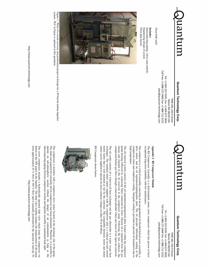
uantum
Quantum
Technology Corp.
PM
B 183, 250 H Street Blaine W
A 98230 USA
Tel: +1-‐604-‐222-‐5539, Fax: +1-‐604-‐677-‐5826 Toll Free: +1-‐888 -‐271-‐9466 Fax: +1-‐888-‐711-‐5222
sales@quantum
-‐technology.com
http://www.quantum
-‐technology.com
(from bulk tank)
Includes: Interconnecting piping, valves and controls. Engineering design of system
Floor plan layout.
Figure 1. Photo of a recent recovery and purification project in Europe for a 50 liter/hr turbine liquefier system
. PLC in Figure is optional in this quotation.
uantum
Quantum
Technology Corp.
PM
B 183, 250 H Street Blaine W
A 98230 USA
Tel: +1-‐604-‐222-‐5539, Fax: +1-‐604-‐677-‐5826 Toll Free: +1-‐888 -‐271-‐9466 Fax: +1-‐888-‐711-‐5222
sales@quantum
-‐technology.com
http://www.quantum
-‐technology.com
Appendix 2. R
S Com
pressor Module
The RS Compressor A
ssembly is a skid-m
ounted, rotary screw com
pressor which has proven to have
exceptional long-term reliability w
ith low m
aintenance.
The compressor is a vertical assem
bly consisting of an encapsulated oil-flooded helical screw assem
bly, a drive m
otor, and an oil separation/impingem
ent plate. The oil provides lubrication, sealing of the com
pressor rotors and compressor cooling. A
dequate cooling is provided to prevent oil breakdown due to
high temperature.
The oil removal system
consists of the oil separation/impingem
ent plate located within the com
pressor pum
p housing followed by coalescing filters connected in series w
herein oil is separated from the gas
stream and returned to the oil reservoir in the com
pressor sump. Follow
ing the last coalescer, the com
pressed helium gas flow
s through a charcoal bed adsorber where any traces of oil vapor are rem
oved.
The oil cooler consists of a water-to-oil heat exchanger and the gas aftercooler is a w
ater- to-gas heat exchanger. The standard m
otor starter supplied with the com
pressor skid is a reduced in-rush current m
otor starter that is wall m
ounted at site by the customer. The com
patible hermetic m
otor and motor
starter can be supplied to operate on most com
mon voltages at either 50 or 60 H
ertz.
RS Compressor show
n below.
The com
pressor is hermetic w
ith a compressor drive m
otor located on the discharge side of the pump.
The shaft seal required for externally driven compressors has been elim
inated. Therefore, it is possible to operate
on sub-atm
ospheric suction
without
the danger
of air
contamination
as long
as the
interconnecting piping between com
pressor suction and liquefier assembly is m
aintained leak tight.
The screw com
pressor includes a hydraulically operated slide valve which loads the com
pressor via button on the O
IT panel on the liquefier. The slide valve loading changes the displacement of the pum
p from
approximately 65 %
flow to 100 %
flow and is m
anually positioned by the operator at start-up. To
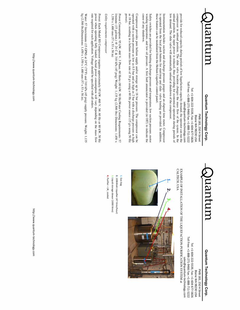
uantum
Quantum
Technology Corp.
PM
B 183, 250 H Street Blaine W
A 98230 USA
Tel: +1-‐604-‐222-‐5539, Fax: +1-‐604-‐677-‐5826 Toll Free: +1-‐888 -‐271-‐9466 Fax: +1-‐888-‐711-‐5222
sales@quantum
-‐technology.com
http://www.quantum
-‐technology.com
provide for reduced capacity during periods of low liquefaction capacity dem
and, the operator can run the com
pressor in unload position. The slide valve location changes the mass flow
of the system. In the
unload position, the input power is reduced, thus providing for econom
ical operation during periods of low
demand. The slide valve w
ill automatically unload at shutdow
n of the compressor.
Instrumentation includes suction and discharge pressure gauges and an elapsed tim
e meter. Com
pressor is operated from
the local push buttons for start/stop and slide- valve loading are provided. In addition, these features can be m
odulated from the H
elium Liquefier control panel.
Safety switches are provided for lim
iting discharge pressure and temperature, low
suction pressure, motor
winding tem
perature, and low oil pressure. A
first fault annunciator is provided (in OIT) to indicate the
cause of any shutdown.
Compressor provides pure helium
supply and/or storage up to 18 bar pressure. The compressor can be
operated with a suction pressure as low
as 0.5 bar and as high as 2 bar with a discharge pressure as high
as 18 bar, resulting in a helium m
ass flow rate of 18 g/s using a 60 H
z power source (15 g/s using 50 H
z pow
er).
Power Consum
ption: 95 kW, 460 V
, 3 Phase, 60 Hertz (80 kW
, 50 Hz)W
ater Cooling Requirements: 57
l/minute (15 gal/m
in.) @ 24 C &
310 kPa (45 psig) Weight: 1,135 kg (2,500 lbs) D
imensions: 1,450 x
1,350 x 1,480 mm
(57 x 53 x 58 in)
Utility requirem
ents compressor
Power: Each M
odel RS Compressor requires approxim
ately 95 kW, 460 V
, 3∅, 60 Hz or 80 kW
, 50 Hz
power w
hen operating fully loaded. Actual pow
er consumption w
ill vary depending on the mass flow
rate required for each application. V
oltage should be specified with all orders.
Water: 57 liters/m
inute (15 GPM
) at 24°C (75°F) and 310 kPa (45 psig) supply pressure. Weight: 1,135
kg (2,500 lbs)Dim
ensions: 1,450 x 1,350 x 1,480 mm
(57 x 53 x 58 in).
uantum
Quantum
Technology Corp.
PM
B 183, 250 H Street Blaine W
A 98230 USA
Tel: +1-‐604-‐222-‐5539, Fax: +1-‐604-‐677-‐5826 Toll Free: +1-‐888 -‐271-‐9466 Fax: +1-‐888-‐711-‐5222
sales@quantum
-‐technology.com
http://www.quantum
-‐technology.com
EXA
MPLE O
F INSTA
LLATIO
N O
F THE LIQ
UEFA
CTION
-PURIFICA
TION
SYSTEM
at CA
LTECH, U
SA
1. Gas bag
2. 100kWatt Liquefier (47 litres/hour)
3. Liquid storage dewar (1000 litres)
4. Purifier – LN2 cooled
uantum
Quantum
Technology Corp.
PM
B 183, 250 H Street Blaine W
A 98230 USA
Tel: +1-‐604-‐222-‐5539, Fax: +1-‐604-‐677-‐5826 Toll Free: +1-‐888 -‐271-‐9466 Fax: +1-‐888-‐711-‐5222
sales@quantum
-‐technology.com
http://www.quantum
-‐technology.com
Appendix 3. H
igh Pressure Helium
Recovery C
ompressor
Characteristics:
Pressure: 4500 psi
Flow
rate: 7.0 cfm
Motor size: 7.5 H
P
Filtering system
included
Electric pow
ered: 3 phase, per user requirements
Standard Scope of Supply
• M
ulti-stage, aircooled piston compressor.
• Electric m
otor drive. •
Autom
atic start-stop control. •
Emergency stop pushbutton.
• A
utomatic condensate drain system
with condensate collector.
• PLC-based control system
(UL).
• Full-voltage m
otor starter. •
Operator keypad for start, stop, reset.
• Backlit LCD
display.
uantum
Quantum
Technology Corp.
PM
B 183, 250 H Street Blaine W
A 98230 USA
Tel: +1-‐604-‐222-‐5539, Fax: +1-‐604-‐677-‐5826 Toll Free: +1-‐888 -‐271-‐9466 Fax: +1-‐888-‐711-‐5222
sales@quantum
-‐technology.com
http://www.quantum
-‐technology.com
• Low
/High inlet pressure sw
itch with gauge.
• H
igh temperature sw
itch. •
Final pressure switch.
• H
ourmeter.
• Coalescing separator at outlet.
• Sound attenuated enclosure.
References
[1] J. Ashman et al., Nucl. Phys. B 328,1 (1989)
[2] D. Boer, M. Diehl, R. Milner, R. Venugopalan, W. Vogelsang, D. Kaplan, H. Montgomeryand S. Vigdor et al., ”Gluons and the quark sea at high energies: Distributions, polarization,tomography”, arXiv:1108.1713 [nucl-th]
[3] A. Accardi, J. L. Albacete, M. Anselmino, N. Armesto, E. C. Aschenauer, A. Bacchetta, D.Boer and W. Brooks et al., Electron Ion Collider: The Next QCD Frontier - Understandingthe glue that binds us all?, arXiv:1212.1701 [nucl-ex].
[4] E. Aschenauer, et al., The RHIC Spin Program: Achievements and Future Opportunities,arXiv:1304.0079 [nucl-ex]
[5] A. Airapetian Phys Rev. D64 (2001) 097101
[6] D. L. Adams Phys. Lett. B 264 (1991), 462
[7] D. Sivers, Phys. Rev. D41 (1990) 83
[8] D. Boer and P. J. Mulders Phys. Rev. D 57, (1998) 5780
[9] J. Huang, Z. B. Kang, I. Vitev and H. Xing, Phys. Rev. D 93,(2016) 014036
[10] E. A. Hawker et al., Phys. Rev. Lett. 80 (1998) 3715
[11] D. L. Adams et al. [FNAL-E704 Collaboration], Phys. Lett. B264 (1991) 462
[12] A. Airapetian et al. [HERMES Collaboration], Phys. Rev. Lett. 103 (2009) 152002
[13] M. Alekseev et al. [COMPASS Collaboration], Phys. Lett. B673 (2009) 127
[14] X. Qian et al. [JLab Hall A Collaboration], Phys.Rev.Lett. 107 2011 072003
[15] H. Gao, et al. E12-11-108 proposal, 2012 https://www.jlab.org/exp prog/proposals/11/PR12-11-108.pdf
[16] Long Range Plan for Nuclear Science http://science.energy.gov/ /me-dia/np/nsac/pdf/2015LRP/2015 LRPNS 091815.pdf
[17] G. Garvey, Phys. Rev. C81 (2010) 055212 and E866 collaboration, Phys. Rev. Lett. 80 (1998)3715
[18] J. C. Collins, Phys. Lett. B536 (2002) 43
[19] Fermilab E1027 proposal, 2012 http://ccd.fnal.gov/techpubs/fermilab-reports-proposal.html(FERMILAB-PROPOSAL-1027)
[20] SD . Drell and TM. Yan, Phys. Rev. Lett. 25 (1971) 316
[21] TMD Collaboration for the Coordinated Theoretical Approach to Transverse MomentumDependent Hadron Structure in QCD, J.W. Qiu, W. Detmold, et al., 2015
[18] J. C. Collins, Nucl. Phys. B 396, 161 (1993)
54
[22] A. V. Belitsky, X. J and F. Yuan, Nucl. Phys. B 656 (2003) 165
[23] D. Boer, P. J. Mulders and F. Pijlman, Nucl. Phys. B 667, 201 (2003)
[24] P. J. Mulders, PoS QCDEV 2015, 005 (2015) [arXiv:1510.05871 [hep-ph]]
[25] M. G. Echevarria, A. Idilbi, Z. B. Kang and I. Vitev, Phys. Rev. D 89, 074013 (2014)
[26] S. M. Aybat, J. C. Collins, J. W. Qiu and T. C. Rogers, Phys. Rev. D 85, 034043 (2012)
[27] S. M. Aybat and T. C. Rogers, Phys. Rev. D 83, 114042 (2011)
[28] P. Sun and F. Yuan, Phys. Rev. D 88, 114012 (2013)
[29] Collins, John C. and Soper, Davison E., Nucl. Phys. B 193, 391 (1981)
[30] S. Arnold, A. Metx, M. Schlegel, Phys. Rev. D79 (2008) 034005
[31] Ji, Xiang-dong and Ma, Jian-ping and Yuan, Feng, Phys. Rev. D 71, 034005 (2005)
[32] Collins, John, Foundations of Perturbative QCD, Cambridge, UK: Univ. Pr. (2011)
[33] Becher, Thomas and Neubert, Matthias, Eur. Phys. J. C 71, 1665 (2011)
[34] Echevarria, Miguel G. and Idilbi, Ahmad and Scimemi, Ignazio, JHEP 1207, 002 (2012)
[35] Chiu, Jui-Yu and Jain, Ambar and Neill, Duff and Rothstein, Ira Z., JHEP 1205, 084 (2012)
[36] Ji, Xiangdong and Sun, Peng and Xiong, Xiaonu and Yuan, Feng, Phys. Rev. D 91, 074009(2015)
[37] Jaffe, R, “Where does the proton really get its spin?”, Physics Today. 48 (9): 24-30, (1995)
[38] D. de Florian, R. Sassot, M. Stratmann and W. Vogelsang, Phys. Rev. Lett. 113, 012001(2014)
[39] S. Meissner, A. Metz and K. Goeke, Phys. Rev. D 76, 034002 (2007)
[40] A. Bacchetta and M. Radici, Phys. Rev. Lett. 107, 212001 (2011)
[41] B. U. Musch, P. Hagler, M. Engelhardt, J. W. Negele and A. Schafer, Phys. Rev. D 85, 094510(2012)
[42] L. Adamczyk et al. [STAR Collaboration], Phys. Rev. Lett. 116, 132301 (2016)
[43] M. Anselmino, M. Boglione, U. D’Alesio, S. Melis, F. Murgia and A. Prokudin, Phys. Rev. D79, 054010 (2009)
[44] Aidala, C.A. and Field, B. and Gamberg, L.P. and Rogers, T.C., Phys. Rev. D 89, 094002(2014)
[45] Kang, Zhong-Bo and Xiao, Bo-Wen and Yuan, Feng, Phys. Rev. Lett. 107, 152002 (2011)
[46] Leader, Elliot and Lorce, Cedric, Phys. Rept. 541, 163-248 (2014)
55
[47] Ji, Xiang-Dong, Phys. Rev. Lett. 78, 610-613 (1997)
[48] K. F. Liu et al., PoS LATTICE 2011, 164 (2011)
[49] L, Adamczyk et al., Phys. Rev. Lett. 116, 132301 (2016)
[50] E906 collaboration, NIM article in preparation
[51] G. R. Court, et al., NIM A 324 (1993) 433
[52] D, Crabb, NIM in Phys. Res. A356 (1995) 9
[53] D. Keller, NIM A 728 (2013) 133-144
[54] O. Kahn, Molecular Magnetism; VCH: New York, (1993)
[55] G. R. Court et al NIM in Phys. Res.,A527 (2004) 253
[56] Kadansky V. “Photoproduktion negativer Pionen an einem polarisierten Neutronentarget”,PhD. thesis. University of Bonn. BONN-IR-75-54 (1975)
[57] C. Dulya et al. NIM A398 (1997) 109
[58] K. B. Unser, AIP Conf. Proc. 252, 266 (1992)
[59] M. Anselmino private communication, based on M. Anselmino et al. Eur. Phys. J. A39 (2009)89
[60] O. E. Krivosheev and N. V. Mokhov, A new MARS and its applications’, Fermilab-Conf-98/043 (1998) and SARE3 KEK Proceedings 97-5 (1997)
[61] G. R. Court , et al. Nucl. Instr. & Meth. A324 (1993) 433
[62] http://pac.fnal.gov/meetings/ Recommendations 2013
[63] http://pac.fnal.gov/meetings/ Recommendations 2015
[64] A. Airapetian, Phys Rev. Lett. 103 (2009) 152002
[65] F. Yuan, Phys. Rev. D 78, 014024 (2008)
[66] Z.-B. Kang, Private communications. (2016)
56