Embed Size (px)
Citation preview
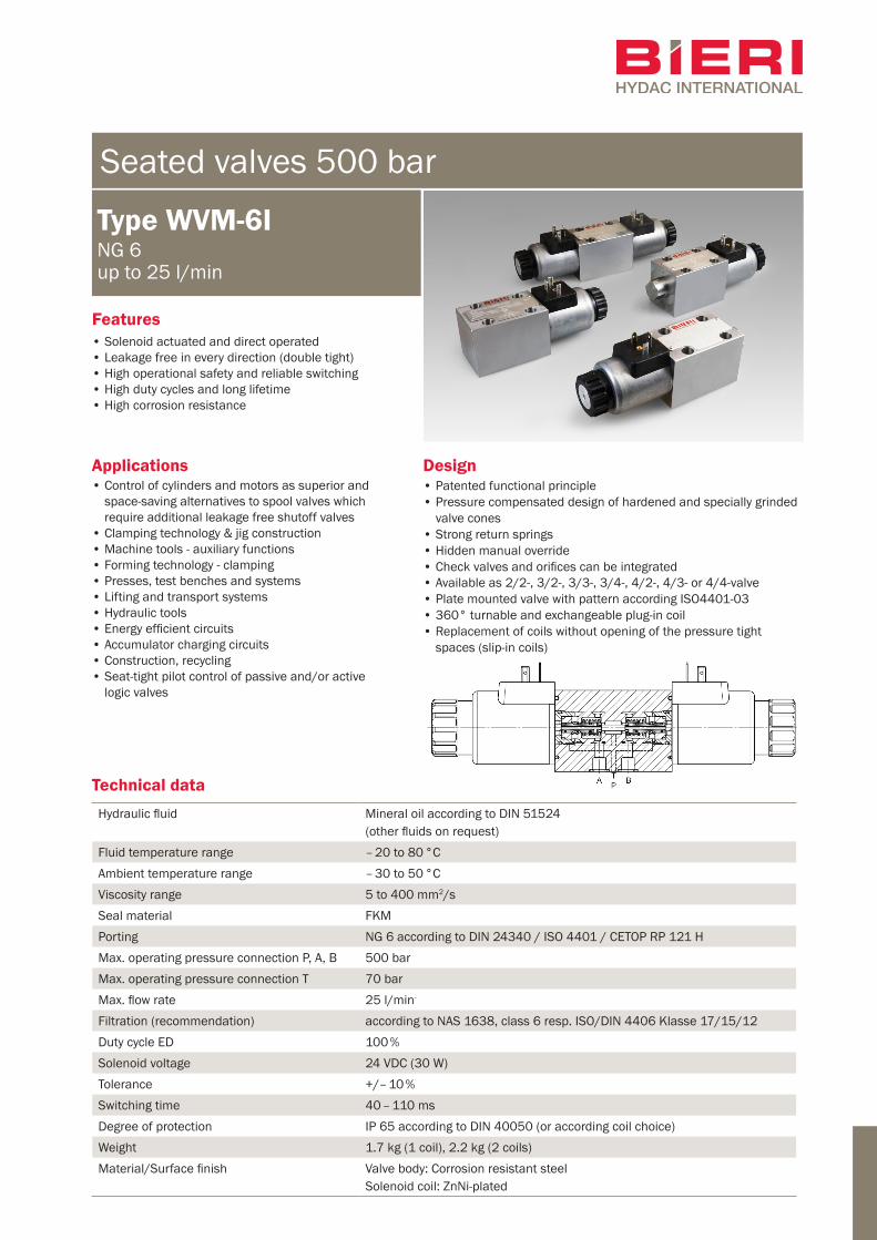
Hydraulic fluid Mineral oil according to DIN 51524(other fluids on request)
Fluid temperature range – 20 to 80 °CAmbient temperature range – 30 to 50 °CViscosity range 5 to 400 mm2/sSeal material FKMPorting NG 6 according to DIN 24340 / ISO 4401 / CETOP RP 121 HMax. operating pressure connection P, A, B 500 barMax. operating pressure connection T 70 barMax. flow rate 25 l/min-
Filtration (recommendation) according to NAS 1638, class 6 resp. ISO/DIN 4406 Klasse 17/15/12Duty cycle ED 100 %Solenoid voltage 24 VDC (30 W)Tolerance +/– 10 % Switching time 40 – 110 msDegree of protection IP 65 according to DIN 40050 (or according coil choice)Weight 1.7 kg (1 coil), 2.2 kg (2 coils)Material/Surface finish Valve body: Corrosion resistant steel
Solenoid coil: ZnNi-plated
Technical data
Applications Design
Features
Type WVM-6ING 6up to 25 l/min
Seated valves 500 bar
• Control of cylinders and motors as superior and space-saving alternatives to spool valves which require additional leakage free shutoff valves
• Clamping technology & jig construction• Machine tools - auxiliary functions• Forming technology - clamping• Presses, test benches and systems• Lifting and transport systems• Hydraulic tools• Energy efficient circuits• Accumulator charging circuits• Construction, recycling• Seat-tight pilot control of passive and/or active
logic valves
• Patented functional principle• Pressure compensated design of hardened and specially grinded
valve cones• Strong return springs• Hidden manual override• Check valves and orifices can be integrated• Available as 2/2-, 3/2-, 3/3-, 3/4-, 4/2-, 4/3- or 4/4-valve• Plate mounted valve with pattern according ISO4401-03• 360° turnable and exchangeable plug-in coil• Replacement of coils without opening of the pressure tight
spaces (slip-in coils)
• Solenoid actuated and direct operated • Leakage free in every direction (double tight)• High operational safety and reliable switching• High duty cycles and long lifetime• High corrosion resistance
2/8
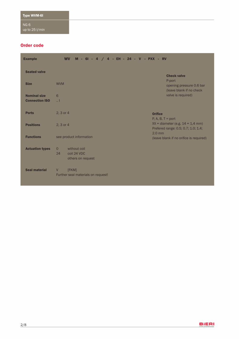
/ - - - ---- RVPXX24EH446IMWV V
Type WVM-6I
NG 6up to 25 l/min
Order code
OrificeP, A, B, T = portXX = diameter (e.g. 14 = 1,4 mm)Prefered range: 0.5; 0.7; 1.0; 1.4; 2.0 mm(leave blank if no orifice is required)
Check valveP-portopening pressure 0.6 bar(leave blank if no check valve is required)
Seal material V [FKM] Further seal materials on request!
Nominal size 6 Connection ISO .. I
Ports 2, 3 or 4
Positions 2, 3 or 4
Functions see product information
Actuation types 0 without coil 24 coil 24 VDC others on request
Size WVM
Seated valve
Example
3/8
Type WVM-6I
NG 6up to 25 l/min
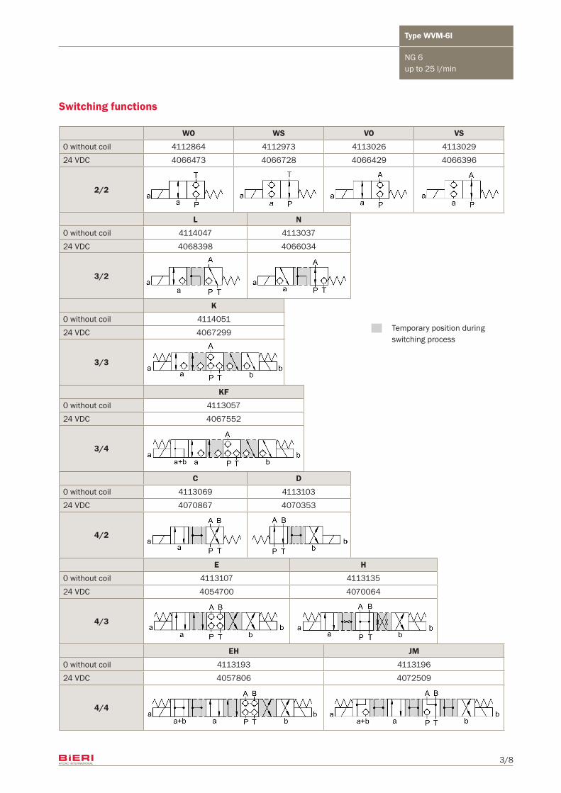
WO WS VO VS
0 without coil 4112864 4112973 4113026 411302924 VDC 4066473 4066728 4066429 4066396
2/2
C D
0 without coil 4113069 411310324 VDC 4070867 4070353
4/2
EH JM
0 without coil 4113193 411319624 VDC 4057806 4072509
4/4
E H
0 without coil 4113107 411313524 VDC 4054700 4070064
4/3
K
0 without coil 411405124 VDC 4067299
3/3
KF
0 without coil 411305724 VDC 4067552
3/4
L N
0 without coil 4114047 411303724 VDC 4068398 4066034
3/2
Switching functions
Temporary position during switching process
4/8
Type WVM-6I
NG 6up to 25 l/min
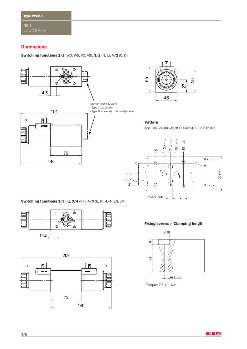
Dimensions
Switching functions 2/2 (WO, WS, VO, VS), 3/2 (N, L), 4/2 (C, D)
Only on 4/2 way valve - Type C, as shown- Type D, inversely (coil on right side)
Switching functions 3/3 (K), 3/4 (KF), 4/3 (E, H), 4/4 (EH, JM)
Fixing screws / Clamping length
acc. DIN 24340-A6/ISO 4401-03 (CETOP 03)
Torque: 7.5 + 1 Nm
Pattern
5/8
Type WVM-6I
NG 6up to 25 l/min
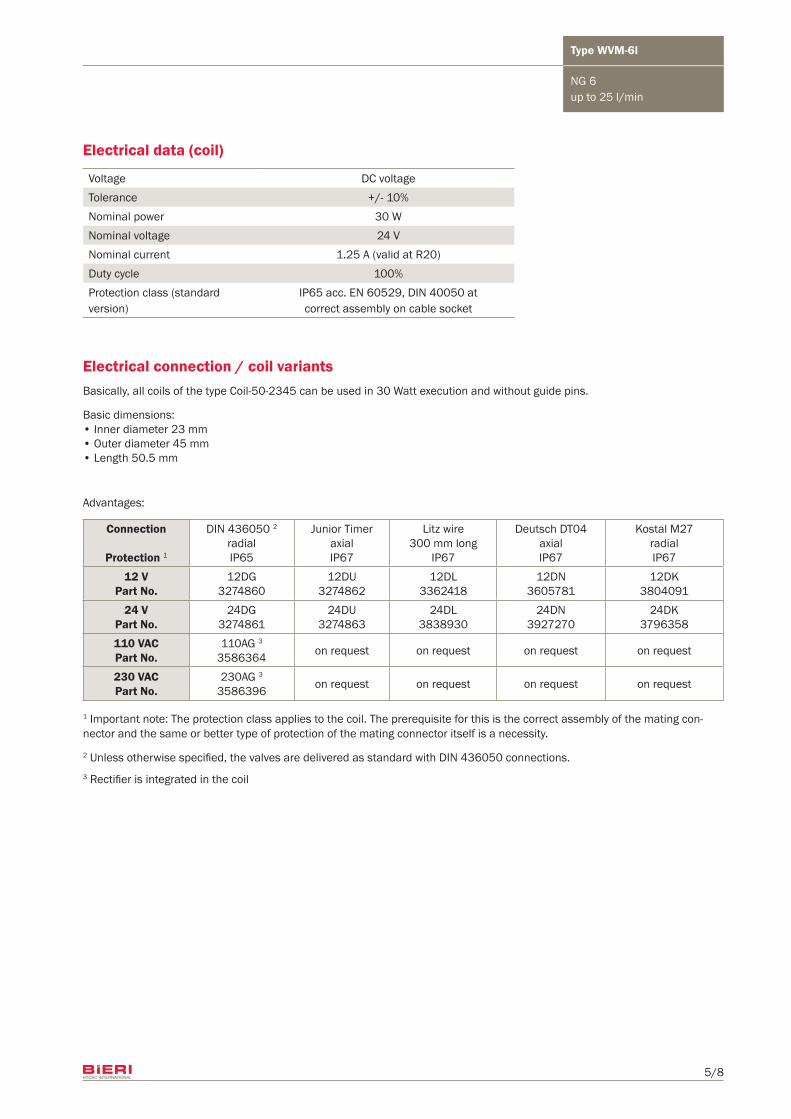
Electrical data (coil)
Electrical connection / coil variants
Voltage DC voltageTolerance +/- 10%Nominal power 30 WNominal voltage 24 VNominal current 1.25 A (valid at R20)Duty cycle 100%Protection class (standard version)
IP65 acc. EN 60529, DIN 40050 at correct assembly on cable socket
Basically, all coils of the type Coil-50-2345 can be used in 30 Watt execution and without guide pins. Basic dimensions:• Inner diameter 23 mm• Outer diameter 45 mm• Length 50.5 mm
Advantages:
2 Unless otherwise specified, the valves are delivered as standard with DIN 436050 connections.3 Rectifier is integrated in the coil
1 Important note: The protection class applies to the coil. The prerequisite for this is the correct assembly of the mating con-nector and the same or better type of protection of the mating connector itself is a necessity.
Connection
Protection 1
DIN 436050 2
radialIP65
Junior TimeraxialIP67
Litz wire300 mm long
IP67
Deutsch DT04axialIP67
Kostal M27radialIP67
12 VPart No.
12DG3274860
12DU3274862
12DL3362418
12DN3605781
12DK3804091
24 VPart No.
24DG3274861
24DU3274863
24DL3838930
24DN3927270
24DK3796358
110 VACPart No.
110AG 3
3586364 on request on request on request on request
230 VACPart No.
230AG 3
3586396 on request on request on request on request
6/8
Type WVM-6I
NG 6up to 25 l/min
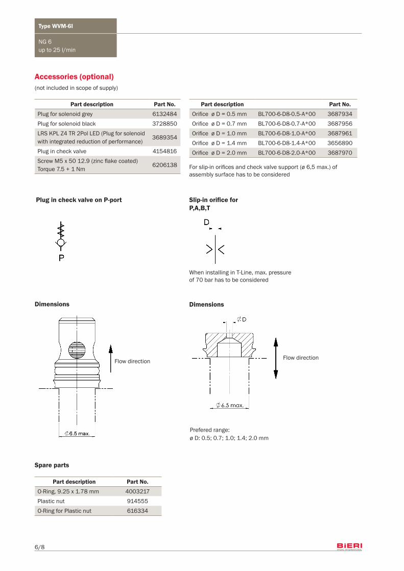
Slip-in orifice forP,A,B,T
Dimensions
When installing in T-Line, max. pressure of 70 bar has to be considered
Dimensions
Plug in check valve on P-port
For slip-in orifices and check valve support (ø 6,5 max.) of assembly surface has to be considered
Accessories (optional)
Part description Part No.
Plug for solenoid grey 6132484Plug for solenoid black 3728850LRS KPL Z4 TR 2Pol LED (Plug for solenoid with integrated reduction of performance)
3689354
Plug in check valve 4154816Screw M5 x 50 12.9 (zinc flake coated)Torque 7.5 + 1 Nm
6206138
Part description Part No.
Orifice ø D = 0.5 mm BL700-6-D8-0.5-A*00 3687934Orifice ø D = 0.7 mm BL700-6-D8-0.7-A*00 3687956Orifice ø D = 1.0 mm BL700-6-D8-1.0-A*00 3687961Orifice ø D = 1.4 mm BL700-6-D8-1.4-A*00 3656890Orifice ø D = 2.0 mm BL700-6-D8-2.0-A*00 3687970
Prefered range:ø D: 0.5; 0.7; 1.0; 1.4; 2.0 mm
Flow directionFlow direction
Spare parts
Part description Part No.
O-Ring, 9.25 x 1.78 mm 4003217Plastic nut 914555O-Ring for Plastic nut 616334
(not included in scope of supply)
7/8
Type WVM-6I
NG 6up to 25 l/min
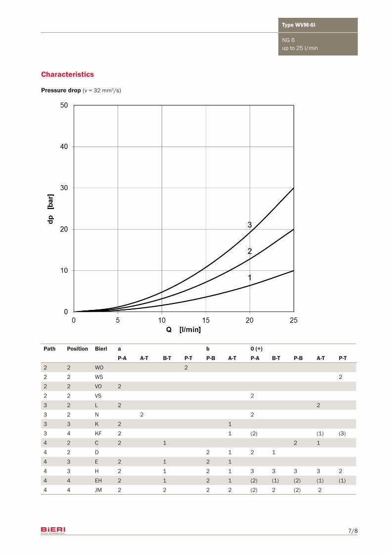
Characteristics
Pressure drop (v = 32 mm2/s)
Path Position Bieri a b 0 (+)
P-A A-T B-T P-T P-B A-T P-A B-T P-B A-T P-T
2 2 WO 22 2 WS 22 2 VO 22 2 VS 23 2 L 2 23 2 N 2 23 3 K 2 13 4 KF 2 1 (2) (1) (3)4 2 C 2 1 2 14 2 D 2 1 2 14 3 E 2 1 2 14 3 H 2 1 2 1 3 3 3 3 24 4 EH 2 1 2 1 (2) (1) (2) (1) (1)4 4 JM 2 2 2 2 (2) 2 (2) 2
Bieri Hydraulik AGKönizstrasse 274 CH-3097 Liebefeld Tel. +41 31 970 09 09 | Fax +41 31 970 09 [email protected] | www.bierihydraulics.com
8/8
p [bar]
Q [l/min]
WVM-6I_1705
HYDAC ADAVersion
DescriptionBenennung
Replaced byErs. durchExchange forErs. für
Old Doc No.alte Dok Nr.Old Mat No.alte Mat Nr.SizeFormat
Sheet ofBlatt von
Vers.Vers.No
Anz.
Modif. ongeänd. amChkd. ongepr.am
Modif. bygeänd. vonChkd. bygepr. von
Notice of change No
Ä.M.Nr.
Chkd.gepr.
Drawngez.
PartTeil
Ord.-Devel.-Project-NoAuftr.-Entw.-Projekt-Nr.
DateDatum NameName
Draw.-NoZeichn.-Nr
/
Finished sizeFertigmaße
MassMasse
overto
über bis
MaterialWerkstoff
/ linear dimensionsLängenmaße
/
Geometrical tolerances / Tolerance classForm u. Lagetoleranz / Toleranzklasse
General tolerancesAllgemeintoleranzen
Surface qualityOberflächenbeschaffenheit
CornersWerkstückkanten
//
/
/
ISO 1302
/
/
/
ISO13715
/
/
SW-Vers.
//
//
Maßstab
//
(mm)
V7.1
10002000
1,2
ISO 2768 - m
H
4155062MBL WVM-6I...AMF
WVM-6I
20.07.2016 RYSERJ
20.07.2016 SCHNEIW
A 28.09.2016 URFERR921852
.. .. .
.
.
. .. .
..
. ..
.
..
.
1 / 1
.
A3
2014
000
2,200 KG
0,53
0,1
36
0,1
301200,3
6300,2
1204000,5
4001000
0,8
1:2
HYDAC INTERNATIONAL M5
10 6.5 max.
(abweichend von Norm)
0 12.7
±0.2
21.5
±0.2
30.2
±0.2
40.5
±0.1
05.1 ±0.2
15.5 ±0.2
25.9 ±0.2
31 ±0.1
0
31.75 ±0.1
0.75 ±0.1
0.75
32.5
T
A
P
B
Lochbild Form A Nenngrösse 6 nach DIN 24340 T2(in Blickrichung auf Platte)
Ebenheit 0.02
50
8 14.5 M5 x 50 -10.9
55
ca.
28
42
10
a b
nicht imLieferumfangenthalten
(nicht im Lieferumfang enthalten)
P
A
T
B
schwarz grau
RV in P
68.5 72 68.5
37.5 17.25 209
46
1/8" Messanschluss (KF nur in A)
27
Technische Spezifikationen
Allgemeine Daten
Lochbild Nenngrösse 6DIN 24340-A6 / ISO 4401-03 / CETOP 03
BefestigungsschraubenKlemmlänge 42mm4 Stk. M5 x 50 -10.9Anziehdrehmoment 7.5Nm +1
Umgebungstemperaturbereich-30 bis 80°C
Hydraulische Daten
HydraulikflüssigkeitMineralöl nach DIN 51524 Teil 1-3
Viskositätsbereich5 - 500 cSt
Ölreinheit (Empfehlung)ISO 4406 20/18/15 oder besser
Nennbetriebsdruck400 bar
Max. Druck in P, A, B420 bar
Max. Druck in Tankleitung 70 bar
Max. Volumenstrom25 l/min
Ventiltypen4/4-EH, 4/4-JM, 3/4-KF mit Einsteck-Rückschlagventil in Pund Druckmessanschlüssen
RV Öffnungsdruck< 1 bar
Elektrische Daten
Nennspannung Un24 V DC +/- 10%
Nennleistung Pn 30 W
Einschaltdauer ED100% bis 55°C Umgebungstemperaturbei 100% Nennspannung
Schaltzahl pro h>3600
Schaltzeiten Ein: <100ms aus: <50ms
Schutzart IP 67 Gewicht 2.2 kg
Massänderungen vorbehalten
A
Schu
tzve
rmer
k IS
O 1
6016
bea
chte
n / O
bser
ving
of p
rote
ctio
n no
tice
ISO
160
16
A
B
C
876541 2 3
D
E
F
C
B
A
E
D
F
5 843 72 61
Vertr
aulic
h / c
onfid
entia
l
500
The information in this brochure relates to the operating condi-tions and applications described.For applications and operating conditions not described, ple-ase contact the relevant technical department.Subject to technical modifications.
Type WVM-6I
NG 6up to 25 l/min
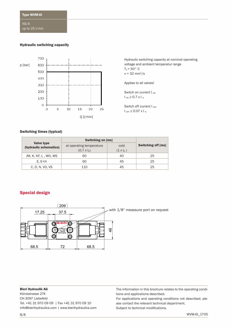
Hydraulic switching capacity
Switching times (typical)
Special design
with 1/8“ meassure port on request
Hydraulic switching capacity at nominal operating voltage and ambient temperatur rangeTa = 50° Cv = 32 mm2/s
Applies to all valves!
Switch on current I ON
I ON ≥ 0.7 x I N
Switch off current I OFF
I OFF ≤ 0.07 x I N
Valve type (hydraulic schematics)
Switching on [ms]Switching off [ms]at operating temperature
(0.7 x IN)cold
(1 x IN )JM, K, KF, L , WO, WS 60 40 25
E, E+H 90 45 25C, D, N, VO, VS 110 45 25


![Nio 20.3 FM [a] CoEx® bean2cup double bean• Cup-sensors • Strength selections menus • Connection for payment systems [MDB] • Boiler : 2x 0.4L • Pressure : max 12 Bar \](https://img.pdfslide.net/doc/110x75/61483b42cee6357ef9253837/nio-203-fm-a-coex-bean2cup-double-bean-a-cup-sensors-a-strength-selections.jpg)


![Data sheet ELIMINATOR® Hermetic filter drier Types DCL ......Filter size Connection type Connection Max. working pressure PS Temperature range [in3] [in.] [bar] [ C] 1.5, 03, 05,](https://img.pdfslide.net/doc/110x75/60c441f84aac8d33e92be655/data-sheet-eliminator-hermetic-filter-drier-types-dcl-filter-size-connection.jpg)