Embed Size (px)
Citation preview

2015 SEATTLE RESIDENTIAL CODE 399
CHAPTER 8
ROOF-CEILING CONSTRUCTION
SECTION R801GENERAL
R801.1 Application. The provisions of this chapter shallcontrol the design and construction of the roof-ceiling systemfor buildings.
R801.2 Requirements. Roof and ceiling construction shallbe capable of accommodating all loads imposed in accor-dance with Section R301 and of transmitting the resultingloads to the supporting structural elements.
R801.3 Roof drainage. In areas where expansive or collaps-ible soils are known to exist, all dwellings shall have a con-trolled method of water disposal from roofs that will collectand discharge roof drainage to the ground surface not less than5 feet (1524 mm) from foundation walls or to an approveddrainage system.
SECTION R802WOOD ROOF FRAMING
R802.1 General. Wood and wood-based products used forload-supporting purposes shall conform to the applicable pro-visions of this section.
R802.1.1 Sawn lumber. Sawn lumber shall be identifiedby a grade mark of an accredited lumber grading orinspection agency and have design values certified by anaccreditation body that complies with DOC PS 20. In lieuof a grade mark, a certificate of inspection issued by alumber grading or inspection agency meeting the require-ments of this section shall be accepted.
R802.1.1.1 End-jointed lumber. Approved end-jointed lumber identified by a grade mark conformingto Section R802.1.1 shall be permitted to be used inter-changeably with solid-sawn members of the same spe-cies and grade. End-jointed lumber used in an assemblyrequired elsewhere in this code to have a fire-resistancerating shall have the designation “Heat-Resistant Adhe-sive” or “HRA” included in its grade mark.
R802.1.2 Structural glued laminated timbers. Gluedlaminated timbers shall be manufactured and identified asrequired in ANSI/AITC A190.1 and ASTM D 3737.
R802.1.3 Structural log members. Structural log mem-bers shall comply with the provisions of ICC 400.
R802.1.4 Structural composite lumber. Structuralcapacities for structural composite lumber shall be estab-lished and monitored in accordance with ASTM D 5456.
R802.1.5 Fire-retardant-treated wood. Fire-retardant-treated wood (FRTW) is any wood product that, whenimpregnated with chemicals by a pressure process or othermeans during manufacture, shall have, when tested inaccordance with ASTM E 84 or UL 723, a listed flamespread index of 25 or less and shows no evidence of signif-
icant progressive combustion where the test is continued foran additional 20-minute period. In addition, the flame frontshall not progress more than 10.5 feet (3200 mm) beyondthe center line of the burners at any time during the test.
R802.1.5.1 Pressure process. For wood productsimpregnated with chemicals by a pressure process, theprocess shall be performed in closed vessels underpressures not less than 50 pounds per square inch gauge(psig) (344.7 kPa).
R802.1.5.2 Other means during manufacture. Forwood products produced by other means during manu-facture the treatment shall be an integral part of themanufacturing process of the wood product. The treat-ment shall provide permanent protection to all surfacesof the wood product.
R802.1.5.3 Testing. For wood products produced byother means during manufacture, other than a pressureprocess, all sides of the wood product shall be tested inaccordance with and produce the results required inSection R802.1.5. Testing of only the front and backfaces of wood structural panels shall be permitted.
R802.1.5.4 Labeling. Fire-retardant-treated lumberand wood structural panels shall be labeled. The labelshall contain:
1. The identification mark of an approved agency inaccordance with Section 1703.5 of the Interna-tional Building Code.
2. Identification of the treating manufacturer.
3. The name of the fire-retardant treatment.
4. The species of wood treated.
5. Flame spread index and smoke-developed index.
6. Method of drying after treatment.
7. Conformance to applicable standards in accor-dance with Sections R802.1.5.5 throughR802.1.5.10.
8. For FRTW exposed to weather, or a damp or wetlocation, the words “No increase in the listedclassification when subjected to the StandardRain Test” (ASTM D 2898).
R802.1.5.5 Strength adjustments. Design values foruntreated lumber and wood structural panels as speci-fied in Section R802.1 shall be adjusted for fire-retar-dant-treated wood. Adjustments to design values shallbe based upon an approved method of investigationthat takes into consideration the effects of the antici-pated temperature and humidity to which the fire-retar-dant-treated wood will be subjected, the type oftreatment and redrying procedures.

ROOF-CEILING CONSTRUCTION
400 2015 SEATTLE RESIDENTIAL CODE
R802.1.5.6 Wood structural panels. The effect oftreatment and the method of redrying after treatment,and exposure to high temperatures and high humiditieson the flexure properties of fire-retardant-treated soft-wood plywood shall be determined in accordance withASTM D 5516. The test data developed by ASTM D5516 shall be used to develop adjustment factors, maxi-mum loads and spans, or both for untreated plywooddesign values in accordance with ASTM D 6305. Eachmanufacturer shall publish the allowable maximumloads and spans for service as floor and roof sheathingfor their treatment.
R802.1.5.7 Lumber. For each species of wood treated,the effect of the treatment and the method of redryingafter treatment and exposure to high temperatures andhigh humidities on the allowable design properties offire-retardant-treated lumber shall be determined inaccordance with ASTM D 5664. The test data developedby ASTM D 5664 shall be used to develop modificationfactors for use at or near room temperature and at ele-vated temperatures and humidity in accordance withASTM D 6841. Each manufacturer shall publish themodification factors for service at temperatures of notless than 80°F (27°C) and for roof framing. The roofframing modification factors shall take into consider-ation the climatological location.
R802.1.5.8 Exposure to weather. Where fire-retar-dant-treated wood is exposed to weather or damp orwet locations, it shall be identified as “Exterior” toindicate there is not an increase in the listed flamespread index as defined in Section R802.1.5 when sub-jected to ASTM D 2898.
R802.1.5.9 Interior applications. Interior fire-retar-dant-treated wood shall have a moisture content of notover 28 percent when tested in accordance with ASTM D3201 procedures at 92-percent relative humidity. Interiorfire-retardant-treated wood shall be tested in accordancewith Section R802.1.5.6 or R802.1.5.7. Interior fire-retardant-treated wood designated as Type A shall betested in accordance with the provisions of this section.
R802.1.5.10 Moisture content. Fire-retardant-treatedwood shall be dried to a moisture content of 19 percentor less for lumber and 15 percent or less for wood struc-tural panels before use. For wood kiln dried after treat-ment (KDAT) the kiln temperatures shall not exceedthose used in kiln drying the lumber and plywood sub-mitted for the tests described in Section R802.1.5.6 forplywood and R802.1.5.7 for lumber.
R802.1.6 Cross-laminated timber. Cross-laminated tim-ber shall be manufactured and identified as required byANSI/APA PRG 320.
R802.1.7 Engineered wood rim board. Engineered woodrim boards shall conform to ANSI/APA PRR 410 or shallbe evaluated in accordance with ASTM D 7672. Structuralcapacities shall be in accordance with ANSI/APA PRR410 or established in accordance with ASTM D 7672. Rimboards conforming to ANSI/APA PRR 410 shall bemarked in accordance with that standard.
R802.2 Design and construction. The framing detailsrequired in Section R802 apply to roofs having a minimumslope of three units vertical in 12 units horizontal (25-percentslope) or greater. Roof-ceilings shall be designed and con-structed in accordance with the provisions of this chapter andFigures R606.11(1), R606.11(2) and R606.11(3) or in accor-dance with AWC NDS. Components of roof-ceilings shall befastened in accordance with Table R602.3(1).
R802.3 Framing details. Rafters shall be framed not morethan 11/2-inches (38 mm) offset from each other to ridgeboard or directly opposite from each other with a gusset plateas a tie. Ridge board shall be not less than 1-inch (25 mm)nominal thickness and not less in depth than the cut end of therafter. At valleys and hips there shall be a valley or hip rafternot less than 2-inch (51 mm) nominal thickness and not lessin depth than the cut end of the rafter. Hip and valley raftersshall be supported at the ridge by a brace to a bearing parti-tion or be designed to carry and distribute the specific load atthat point. Where the roof pitch is less than three units verti-cal in 12 units horizontal (25-percent slope), structural mem-bers that support rafters and ceiling joists, such as ridgebeams, hips and valleys, shall be designed as beams.
R802.3.1 Ceiling joist and rafter connections. Ceilingjoists and rafters shall be nailed to each other in accor-dance with Table R802.5.1(9), and the rafter shall benailed to the top wall plate in accordance with TableR602.3(1). Ceiling joists shall be continuous or securelyjoined in accordance with Table R802.5.1(9) where theymeet over interior partitions and are nailed to adjacent raf-ters to provide a continuous tie across the building wheresuch joists are parallel to the rafters.
Where ceiling joists are not connected to the rafters atthe top wall plate, joists connected higher in the attic shallbe installed as rafter ties, or rafter ties shall be installed toprovide a continuous tie. Where ceiling joists are not paral-lel to rafters, rafter ties shall be installed. Rafter ties shall benot less than 2 inches by 4 inches (51 mm by 102 mm)(nominal), installed in accordance with the connectionrequirements in Table R802.5.1(9), or connections ofequivalent capacities shall be provided. Where ceilingjoists or rafter ties are not provided, the ridge formed bythese rafters shall be supported by a wall or girder designedin accordance with accepted engineering practice.
Collar ties or ridge straps to resist wind uplift shall beconnected in the upper third of the attic space in accor-dance with Table R602.3(1).
Collar ties shall be not less than 1 inch by 4 inches (25mm by 102 mm) (nominal), spaced not more than 4 feet(1219 mm) on center.
R802.3.2 Ceiling joists lapped. Ends of ceiling joistsshall be lapped not less than 3 inches (76 mm) or buttedover bearing partitions or beams and toenailed to the bear-ing member. Where ceiling joists are used to provide resis-tance to rafter thrust, lapped joists shall be nailed togetherin accordance with Table R802.5.1(9) and butted joistsshall be tied together in a manner to resist such thrust.Joists that do not resist thrust shall be permitted to benailed in accordance with Table R602.3(1).

ROOF-CEILING CONSTRUCTION
2015 SEATTLE RESIDENTIAL CODE 401
TABLE R802.4(1)CEILING JOIST SPANS FOR COMMON LUMBER SPECIES
(Uninhabitable attics without storage, live load = 10 psf, L/∆ = 240)
(continued)
CEILING JOISTSPACING (inches)
SPECIES AND GRADE
DEAD LOAD = 5 psf
2 × 4 2 × 6 2 × 8 2 × 10
Maximum ceiling joist spans
(feet - inches) (feet - inches) (feet - inches) (feet - inches)
12
Douglas fir-larch SS 13-2 20-8 Note a Note a
Douglas fir-larch #1 12-8 19-11 Note a Note a
Douglas fir-larch #2 12-5 19-6 25-8 Note a
Douglas fir-larch #3 11-1 16-3 20-7 25-2
Hem-fir SS 12-5 19-6 25-8 Note a
Hem-fir #1 12-2 19-1 25-2 Note a
Hem-fir #2 11-7 18-2 24-0 Note a
Hem-fir #3 10-10 15-10 20-1 24-6
Southern pine SS 12-11 20-3 Note a Note a
Southern pine #1 12-5 19-6 25-8 Note a
Southern pine #2 11-10 18-8 24-7 Note a
Southern pine #3 10-1 14-11 18-9 22-9
Spruce-pine-fir SS 12-2 19-1 25-2 Note a
Spruce-pine-fir #1 11-10 18-8 24-7 Note a
Spruce-pine-fir #2 11-10 18-8 24-7 Note a
Spruce-pine-fir #3 10-10 15-10 20-1 24-6
16
Douglas fir-larch SS 11-11 18-9 24-8 Note a
Douglas fir-larch #1 11-6 18-1 23-10 Note a
Douglas fir-larch #2 11-3 17-8 23-4 Note a
Douglas fir-larch #3 9-7 14-1 17-10 21-9
Hem-fir SS 11-3 17-8 23-4 Note a
Hem-fir #1 11-0 17-4 22-10 Note a
Hem-fir #2 10-6 16-6 21-9 Note a
Hem-fir #3 9-5 13-9 17-5 21-3
Southern pine SS 11-9 18-5 24-3 Note a
Southern pine #1 11-3 17-8 23-10 Note a
Southern pine #2 10-9 16-11 21-7 25-7
Southern pine #3 8-9 12-11 16-3 19-9
Spruce-pine-fir SS 11-0 17-4 22-10 Note a
Spruce-pine-fir #1 10-9 16-11 22-4 Note a
Spruce-pine-fir #2 10-9 16-11 22-4 Note a
Spruce-pine-fir #3 9-5 13-9 17-5 21-3
R802.3.3 Blocking. Blocking shall be a minimum of util-ity grade lumber.
R802.4 Allowable ceiling joist spans. Spans for ceiling joistsshall be in accordance with Tables R802.4(1) and R802.4(2).For other grades and species and for other loading conditions,refer to the AWC STJR.
R802.5 Allowable rafter spans. Spans for rafters shall be inaccordance with Tables R802.5.1(1) through R802.5.1(8).For other grades and species and for other loading conditions,refer to the AWC STJR. The span of each rafter shall be mea-sured along the horizontal projection of the rafter.
R802.5.1 Purlins. Installation of purlins to reduce the spanof rafters is permitted as shown in Figure R802.5.1. Purlinsshall be sized not less than the required size of the raftersthat they support. Purlins shall be continuous and shall besupported by 2-inch by 4-inch (51 mm by 102 mm) bracesinstalled to bearing walls at a slope not less than 45 degrees(0.79 rad) from the horizontal. The braces shall be spacednot more than 4 feet (1219 mm) on center and the unbracedlength of braces shall not exceed 8 feet (2438 mm).

ROOF-CEILING CONSTRUCTION
402 2015 SEATTLE RESIDENTIAL CODE
TABLE R802.4(1)—continuedCEILING JOIST SPANS FOR COMMON LUMBER SPECIES
(Uninhabitable attics without storage, live load = 10 psf, L/∆ = 240)
Check sources for availability of lumber in lengths greater than 20 feet.
For SI: 1 inch = 25.4 mm, 1 foot = 304.8 mm, 1 pound per square foot = 0.0479 kPa.
a. Span exceeds 26 feet in length.
CEILING JOISTSPACING (inches)
SPECIES AND GRADE
DEAD LOAD = 5 psf
2 × 4 2 × 6 2 × 8 2 × 10
Maximum ceiling joist spans
(feet - inches) (feet - inches) (feet - inches) (feet - inches)
19.2
Douglas fir-larch SS 11-3 17-8 23-3 Note a
Douglas fir-larch #1 10-10 17-0 22-5 Note a
Douglas fir-larch #2 10-7 16-8 21-4 26-0
Douglas fir-larch #3 8-9 12-10 16-3 19-10
Hem-fir SS 10-7 16-8 21-11 Note a
Hem-fir #1 10-4 16-4 21-6 Note a
Hem-fir #2 9-11 15-7 20-6 25-3
Hem-fir #3 8-7 12-6 15-10 19-5
Southern -pine SS 11-0 17-4 22-10 Note a
Southern pine #1 10-7 16-8 22-0 Note a
Southern pine #2 10-2 15-7 19-8 23-5
Southern pine #3 8-0 11-9 14-10 18-0
Spruce-pine-fir SS 10-4 16-4 21-6 Note a
Spruce-pine-fir #1 10-2 15-11 21-0 25-8
Spruce-pine-fir #2 10-2 15-11 21-0 25-8
Spruce-pine-fir #3 8-7 12-6 15-10 19-5
24
Douglas fir-larch SS 10-5 16-4 21-7 Note a
Douglas fir-larch #1 10-0 15-9 20-1 24-6
Douglas fir-larch #2 9-10 15-0 19-1 23-3
Douglas fir-larch #3 7-10 11-6 14-7 17-9
Hem-fir SS 9-10 15-6 20-5 Note a
Hem-fir #1 9-8 15-2 19-10 24-3
Hem-fir #2 9-2 14-5 18-6 22-7
Hem-fir #3 7-8 11-2 14-2 17-4
Southern pine SS 10-3 16-1 21-2 Note a
Southern pine #1 9-10 15-6 20-5 24-0
Southern pine #2 9-3 13-11 17-7 20-11
Southern pine #3 7-2 10-6 13-3 16-1
Spruce-pine-fir SS 9-8 15-2 19-11 25-5
Spruce-pine-fir #1 9-5 14-9 18-9 22-11
Spruce-pine-fir #2 9-5 14-9 18-9 22-11
Spruce-pine-fir #3 7-8 11-2 14-2 17-4

ROOF-CEILING CONSTRUCTION
2015 SEATTLE RESIDENTIAL CODE 403
TABLE R802.4(2)CEILING JOIST SPANS FOR COMMON LUMBER SPECIES
(Uninhabitable attics with limited storage, live load = 20 psf, L/∆ = 240)
(continued)
CEILING JOISTSPACING (inches)
SPECIES AND GRADE
DEAD LOAD = 10 psf
2 × 4 2 × 6 2 × 8 2 × 10
Maximum ceiling joist spans
(feet - inches) (feet - inches) (feet - inches) (feet - inches)
12
Douglas fir-larch SS 10-5 16-4 21-7 Note a
Douglas fir-larch #1 10-0 15-9 20-1 24-6
Douglas fir-larch #2 9-10 15-0 19-1 23-3
Douglas fir-larch #3 7-10 11-6 14-7 17-9
Hem-fir SS 9-10 15-6 20-5 Note a
Hem-fir #1 9-8 15-2 19-10 24-3
Hem-fir #2 9-2 14-5 18-6 22-7
Hem-fir #3 7-8 11-2 14-2 17-4
Southern pine SS 10-3 16-1 21-2 Note a
Southern pine #1 9-10 15-6 20-5 24-0
Southern pine #2 9-3 13-11 17-7 20-11
Southern pine #3 7-2 10-6 13-3 16-1
Spruce-pine-fir SS 9-8 15-2 19-11 25-5
Spruce-pine-fir #1 9-5 14-9 18-9 22-11
Spruce-pine-fir #2 9-5 14-9 18-9 22-11
Spruce-pine-fir #3 7-8 11-2 14-2 17-4
16
Douglas fir-larch SS 9-6 14-11 19-7 25-0
Douglas fir-larch #1 9-1 13-9 17-5 21-3
Douglas fir-larch #2 8-11 13-0 16-6 20-2
Douglas fir-larch #3 6-10 9-11 12-7 15-5
Hem-fir SS 8-11 14-1 18-6 23-8
Hem-fir #1 8-9 13-7 17-2 21-0
Hem-fir #2 8-4 12-8 16-0 19-7
Hem-fir #3 6-8 9-8 12-4 15-0
Southern pine SS 9-4 14-7 19-3 24-7
Southern pine #1 8-11 14-0 17-9 20-9
Southern pine #2 8-0 12-0 15-3 18-1
Southern pine #3 6-2 9-2 11-6 14-0
Spruce-pine-fir SS 8-9 13-9 18-1 23-1
Spruce-pine-fir #1 8-7 12-10 16-3 19-10
Spruce-pine-fir #2 8-7 12-10 16-3 19-10
Spruce-pine-fir #3 6-8 9-8 12-4 15-0

ROOF-CEILING CONSTRUCTION
404 2015 SEATTLE RESIDENTIAL CODE
TABLE R802.4(2)—continuedCEILING JOIST SPANS FOR COMMON LUMBER SPECIES
(Uninhabitable attics with limited storage, live load = 20 psf, L/∆ = 240)
Check sources for availability of lumber in lengths greater than 20 feet.
For SI: 1 inch = 25.4 mm, 1 foot = 304.8 mm, 1 pound per square foot = 0.0479 kPa.
a. Span exceeds 26 feet in length.
CEILING JOISTSPACING (inches)
SPECIES AND GRADE
DEAD LOAD = 10 psf
2 × 4 2 × 6 2 × 8 2 × 10
Maximum ceiling joist spans
(feet - inches) (feet - inches) (feet - inches) (feet - inches)
19.2
Douglas fir-larch SS 8-11 14-0 18-5 23-7
Douglas fir-larch #1 8-7 12-6 15-10 19-5
Douglas fir-larch #2 8-2 11-11 15-1 18-5
Douglas fir-larch #3 6-2 9-1 11-6 14-1
Hem-fir SS 8-5 13-3 17-5 22-3
Hem-fir #1 8-3 12-4 15-8 19-2
Hem-fir #2 7-10 11-7 14-8 17-10
Hem-fir #3 6-1 8-10 11-3 13-8
Southern pine SS 8-9 13-9 18-2 23-1
Southern pine #1 8-5 12-9 16-2 18-11
Southern pine #2 7-4 11-0 13-11 16-6
Southern pine #3 5-8 8-4 10-6 12-9
Spruce-pine-fir SS 8-3 12-11 17-1 21-8
Spruce-pine-fir #1 8-0 11-9 14-10 18-2
Spruce-pine-fir #2 8-0 11-9 14-10 18-2
Spruce-pine-fir #3 6-1 8-10 11-3 13-8
24
Douglas fir-larch SS 8-3 13-0 17-2 21-3
Douglas fir-larch #1 7-8 11-2 14-2 17-4
Douglas fir-larch #2 7-3 10-8 13-6 16-5
Douglas fir-larch #3 5-7 8-1 10-3 12-7
Hem-fir SS 7-10 12-3 16-2 20-6
Hem-fir #1 7-7 11-1 14-0 17-1
Hem-fir #2 7-1 10-4 13-1 16-0
Hem-fir #3 5-5 7-11 10-0 12-3
Southern pine SS 8-1 12-9 16-10 21-6
Southern pine #1 7-8 11-5 14-6 16-11
Southern pine #2 6-7 9-10 12-6 14-9
Southern pine #3 5-1 7-5 9-5 11-5
Spruce-pine-fir SS 7-8 12-0 15-10 19-5
Spruce-pine-fir #1 7-2 10-6 13-3 16-3
Spruce-pine-fir #2 7-2 10-6 13-3 16-3
Spruce-pine-fir #3 5-5 7-11 10-0 12-3

ROOF-CEILING CONSTRUCTION
2015 SEATTLE RESIDENTIAL CODE 405
TABLE R802.5.1(1)RAFTER SPANS FOR COMMON LUMBER SPECIES
(Roof live load = 20 psf, ceiling not attached to rafters, L/∆ = 180)
(continued)
RAFTERSPACING(inches)
SPECIES AND GRADE
DEAD LOAD = 10 psf DEAD LOAD = 20 psf
2 × 4 2 × 6 2 × 8 2 × 10 2 × 12 2 × 4 2 × 6 2 × 8 2 × 10 2 × 12
Maximum rafter spansa
(feet -inches)
(feet -inches)
(feet -inches)
(feet -inches)
(feet -inches)
(feet -inches)
(feet -inches)
(feet -inches)
(feet -inches)
(feet -inches)
12
Douglas fir-larch SS 11-6 18-0 23-9 Note b Note b 11-6 18-0 23-9 Note b Note b
Douglas fir-larch #1 11-1 17-4 22-5 Note b Note b 10-6 15-4 19-5 23-9 Note b
Douglas fir-larch #2 10-10 16-10 21-4 26-0 Note b 10-0 14-7 18-5 22-6 26-0
Douglas fir-larch #3 8-9 12-10 16-3 19-10 23-0 7-7 11-1 14-1 17-2 19-11
Hem-fir SS 10-10 17-0 22-5 Note b Note b 10-10 17-0 22-5 Note b Note b
Hem-fir #1 10 -7 16-8 22-0 Note b Note b 10-4 15-2 19-2 23-5 Note b
Hem-fir #2 10-1 15-11 20-8 25-3 Note b 9-8 14-2 17-11 21-11 25-5
Hem-fir #3 8-7 12-6 15-10 19-5 22-6 7-5 10-10 13-9 16-9 19-6
Southern pine SS 11-3 17-8 23-4 Note b Note b 11-3 17-8 23-4 Note b Note b
Southern pine #1 10-10 17-0 22-5 Note b Note b 10-6 15-8 19-10 23-2 Note b
Southern pine #2 10-4 15-7 19-8 23-5 Note b 9-0 13-6 17-1 20-3 23-10
Southern pine #3 8-0 11-9 14-10 18-0 21-4 6-11 10-2 12-10 15-7 18-6
Spruce-pine-fir SS 10-7 16-8 21-11 Note b Note b 10-7 16-8 21-9 Note b Note b
Spruce-pine-fir #1 10-4 16-3 21-0 25-8 Note b 9-10 14-4 18-2 22-3 25-9
Spruce-pine-fir #2 10-4 16-3 21-0 25-8 Note b 9-10 14-4 18-2 22-3 25-9
Spruce-pine-fir #3 8-7 12-6 15-10 19-5 22-6 7-5 10-10 13-9 16-9 19-6
16
Douglas fir-larch SS 10-5 16-4 21-7 Note b Note b 10-5 16-3 20-7 25-2 Note b
Douglas fir-larch #1 10-0 15-4 19-5 23-9 Note b 9-1 13-3 16-10 20-7 23-10
Douglas fir-larch #2 9-10 14-7 18-5 22-6 26-0 8-7 12-7 16-0 19-6 22-7
Douglas fir-larch #3 7-7 11-1 14-1 17-2 19-11 6-7 9-8 12-12 14-11 17-3
Hem-fir SS 9-10 15-6 20-5 Note b Note b 9-10 15-6 19-11 24-4 Note b
Hem-fir #1 9-8 15-2 19-2 23-5 Note b 9-0 13-1 16-7 20-4 23-7
Hem-fir #2 9-2 14-2 17-11 21-11 25-5 8-5 12-3 15-6 18-11 22-0
Hem-fir #3 7-5 10-10 13-9 16-9 19-6 6-5 9-5 11-11 14-6 16-10
Southern pine SS 10-3 16-1 21-2 Note b Note b 10-3 16-1 21-2 25-7 Note b
Southern pine #1 9-10 15-6 19-10 23-2 Note b 9-1 13-7 17-2 20-1 23-10
Southern pine #2 9-0 13-6 17-1 20-3 23-10 7-9 11-8 14-9 17-6 20-8
Southern pine #3 6-11 10-2 12-10 15-7 18-6 6-0 8-10 11-2 13-6 16-0
Spruce-pine-fir SS 9-8 15-2 19-11 25-5 Note b 9-8 14-10 18-10 23-0 Note b
Spruce-pine-fir #1 9-5 14-4 18-2 22-3 25-9 8-6 12-5 15-9 19-3 22-4
Spruce-pine-fir #2 9-5 14-4 18-2 22-3 25-9 8-6 12-5 15-9 19-3 22-4
Spruce-pine-fir #3 7-5 10-10 13-9 16-9 19-6 6-5 9-5 11-11 14-6 16-10
19.2
Douglas fir-larch SS 9-10 15-5 20-4 25-11 Note b 9-10 14-10 18-10 23-0 Note b
Douglas fir-larch #1 9-5 14-0 17-9 21-8 25-2 8-4 12-2 15-4 18-9 21-9
Douglas fir-larch #2 9-1 13-3 16-10 20-7 23-10 7-10 11-6 14-7 17-10 20-8
Douglas fir-larch #3 6-11 10-2 12-10 15-8 18-3 6-0 8-9 11-2 12-7 15-9
Hem-fir SS 9-3 14-7 19-2 24-6 Note b 9-3 14-4 18-2 22-3 25-9
Hem-fir #1 9-1 13-10 17-6 21-5 24-10 8-2 12-0 15-2 18-6 21-6
Hem-fir #2 8-8 12-11 16-4 20-0 23-2 7-8 11-2 14-2 17-4 20-1
Hem-fir #3 6-9 9-11 12-7 15-4 17-9 5-10 8-7 10-10 13-3 15-5
Southern pine SS 9-8 15-2 19-11 25-5 Note b 9-8 15-2 19-7 23-4 Note b
Southern pine #1 9-3 14-3 18-1 21-2 25-2 8-4 12-4 15-8 18-4 21-9
Southern pine #2 8-2 12-3 15-7 18-6 21-9 7-1 10-8 13-6 16-0 18-10
Southern pine #3 6-4 9-4 11-9 14-3 16-10 5-6 8-1 10-2 12-4 14-7
Spruce-pine-fir SS 9-1 14-3 18-9 23-11 Note b 9-1 13-7 17-2 21-0 24-4
Spruce-pine-fir #1 8-10 13-1 16-7 20-3 23-6 7-9 11-4 14-4 17-7 20-4
Spruce-pine-fir #2 8-10 13-1 16-7 20-3 23-6 7-9 11-4 14-4 17-7 20-4
Spruce-pine-fir #3 6-9 9-11 12-7 15-4 17-9 5-10 8-7 10-10 13-3 15-5

ROOF-CEILING CONSTRUCTION
406 2015 SEATTLE RESIDENTIAL CODE
TABLE R802.5.1(1)—continuedRAFTER SPANS FOR COMMON LUMBER SPECIES
(Roof live load = 20 psf, ceiling not attached to rafters, L/∆ = 180)
Check sources for availability of lumber in lengths greater than 20 feet.
For SI: 1 inch = 25.4 mm, 1 foot = 304.8 mm, 1 pound per square foot = 0.0479 kPa.
a. The tabulated rafter spans assume that ceiling joists are located at the bottom of the attic space or that some other method of resisting the outward push of therafters on the bearing walls, such as rafter ties, is provided at that location. Where ceiling joists or rafter ties are located higher in the attic space, the rafterspans shall be multiplied by the following factors:
RAFTERSPACING(inches)
SPECIES AND GRADE
DEAD LOAD = 10 psf DEAD LOAD = 20 psf
2 × 4 2 × 6 2 × 8 2 × 10 2 × 12 2 × 4 2 × 6 2 × 8 2 × 10 2 × 12
Maximum rafter spansa
(feet -inches)
(feet -inches)
(feet -inches)
(feet -inches)
(feet -inches)
(feet -inches)
(feet -inches)
(feet -inches)
(feet -inches)
(feet -inches)
24
Douglas fir-larch SS 9-1 14-4 18-10 23-9 Note b 9-1 13-3 16-10 20-7 23-10
Douglas fir-larch #1 8-7 12-6 15-10 19-5 22-6 7-5 10-10 13-9 16-9 19-6
Douglas fir-larch #2 8-2 11-11 15-1 18-5 21-4 7-0 10-4 13-0 15-11 18-6
Douglas fir-larch #3 6-2 9-1 11-6 14-1 16-3 5-4 7-10 10-0 12-2 14-1
Hem-fir SS 8-7 13-6 17-10 22-9 Note b 8-7 12-10 16-3 19-10 23-0
Hem-fir #1 8-5 12-4 15-8 19-2 22-2 7-4 10-9 13-7 16-7 19-3
Hem-fir #2 7-11 11-7 14-8 17-10 20-9 6-10 10-0 12-8 15-6 17-11
Hem-fir #3 6-1 8-10 11-3 13-8 15-11 5-3 7-8 9-9 11-10 13-9
Southern pine SS 8-11 14-1 18-6 23-8 Note b 8-11 13-10 17-6 20-10 24-8
Southern pine #1 8-7 12-9 16-2 18-11 22-6 7-5 11-1 14-0 16-5 19-6
Southern pine #2 7-4 11-0 13-11 16-6 19-6 6-4 9-6 12-1 14-4 16-10
Southern pine #3 5-8 8-4 10-6 12-9 15-1 4-11 7-3 9-1 11-0 13-1
Spruce-pine-fir SS 8-5 13-3 17-5 21-8 25-2 8-4 12-2 15-4 18-9 21-9
Spruce-pine-fir #1 8-0 11-9 14-10 18-2 21-0 6-11 10-2 12-10 15-8 18-3
Spruce-pine-fir #2 8-0 11-9 14-10 18-2 21-0 6-11 10-2 12-10 15-8 18-3
Spruce-pine-fir #3 6-1 8-10 11-3 13-8 15-11 5-3 7-8 9-9 11-10 13-9
where:
HC = Height of ceiling joists or rafter ties measured vertically above the top of the rafter support walls.
HR = Height of roof ridge measured vertically above the top of the rafter support walls.
b. Span exceeds 26 feet in length.
HC/HR Rafter Span Adjustment Factor
1/3 0.67
1/4 0.76
1/5 0.83
1/6 0.90
1/7.5 or less 1.00

ROOF-CEILING CONSTRUCTION
2015 SEATTLE RESIDENTIAL CODE 407
TABLE R802.5.1(2)RAFTER SPANS FOR COMMON LUMBER SPECIES
(Roof live load = 20 psf, ceiling attached to rafters, L/∆ = 240)
(continued)
RAFTERSPACING(inches)
SPECIES AND GRADE
DEAD LOAD = 10 psf DEAD LOAD = 20 psf
2 × 4 2 × 6 2 × 8 2 × 10 2 × 12 2 × 4 2 × 6 2 × 8 2 × 10 2 × 12
Maximum rafter spansa
(feet -inches)
(feet -inches)
(feet -inches)
(feet -inches)
(feet -inches)
(feet -inches)
(feet -inches)
(feet -inches)
(feet -inches)
(feet -inches)
12
Douglas fir-larch SS 10-5 16-4 21-7 Note b Note b 10-5 16-4 21-7 Note b Note b
Douglas fir-larch #1 10-0 15-9 20-10 Note b Note b 10-0 15-4 19-5 23-9 Note b
Douglas fir-larch #2 9-10 15-6 20-5 26-0 Note b 9-10 14-7 18-5 22-6 26-0
Douglas fir-larch #3 8-9 12-10 16-3 19-10 23-0 7-7 11-1 14-1 17-2 19-11
Hem-fir SS 9-10 15-6 20-5 Note b Note b 9-10 15-6 20-5 Note b Note b
Hem-fir #1 9-8 15-2 19-11 25-5 Note b 9-8 15-2 19-2 23-5 Note b
Hem-fir #2 9-2 14-5 19-0 24-3 Note b 9-2 14-2 17-11 21-11 25-5
Hem-fir #3 8-7 12-6 15-10 19-5 22-6 7-5 10-10 13-9 16-9 19-6
Southern pine SS 10-3 16-1 21-2 Note b Note b 10-3 16-1 21-2 Note b Note b
Southern pine #1 9-10 15-6 20-5 Note b Note b 9-10 15-6 19-10 23-2 Note b
Southern pine #2 9-5 14-9 19-6 23-5 Note b 9-0 13-6 17-1 20-3 23-10
Southern pine #3 8-0 11-9 14-10 18-0 21-4 6-11 10-2 12-10 15-7 18-6
Spruce-pine-fir SS 9-8 15-2 19-11 25-5 Note b 9-8 15-2 19-11 25-5 Note b
Spruce-pine-fir #1 9-5 14-9 19-6 24-10 Note b 9-5 14-4 18-2 22-3 25-9
Spruce-pine-fir #2 9-5 14-9 19-6 24-10 Note b 9-5 14-4 18-2 22-3 25-9
Spruce-pine-fir #3 8-7 12-6 15-10 19-5 22-6 7-5 10-10 13-9 16-9 19-6
16
Douglas fir-larch SS 9-6 14-11 19-7 25-0 Note b 9-6 14-11 19-7 25-0 Note b
Douglas fir-larch #1 9-1 14-4 18-11 23-9 Note b 9-1 13-3 16-10 20-7 23-10
Douglas fir-larch #2 8-11 14-1 18-5 22-6 26-0 8-7 12-7 16-0 19-6 22-7
Douglas fir-larch #3 7-7 11-1 14-1 17-2 19-11 6-7 9-8 12-2 14-11 17-3
Hem-fir SS 8-11 14-1 18-6 23-8 Note b 8-11 14-1 18-6 23-8 Note b
Hem-fir #1 8-9 13-9 18-1 23-1 Note b 8-9 13-1 16-7 20-4 23-7
Hem-fir #2 8-4 13-1 17-3 21-11 25-5 8-4 12-3 15-6 18-11 22-0
Hem-fir #3 7-5 10-10 13-9 16-9 19-6 6-5 9-5 11-11 14-6 16-10
Southern pine SS 9-4 14-7 19-3 24-7 Note b 9-4 14-7 19-3 24-7 Note b
Southern pine #1 8-11 14-1 18-6 23-2 Note b 8-11 13-7 17-2 20-1 23-10
Southern pine #2 8-7 13-5 17-1 20-3 23-10 7-9 11-8 14-9 17-6 20-8
Southern pine #3 6-11 10-2 12-10 15-7 18-6 6-0 8-10 11-2 13-6 16-0
Spruce-pine-fir SS 8-9 13-9 18-1 23-1 Note b 8-9 13-9 18-1 23-0 Note b
Spruce-pine-fir #1 8-7 13-5 17-9 22-3 25-9 8-6 12-5 15-9 19-3 22-4
Spruce-pine-fir #2 8-7 13-5 17-9 22-3 25-9 8-6 12-5 15-9 19-3 22-4
Spruce-pine-fir #3 7-5 10-10 13-9 16-9 19-6 6-5 9-5 11-11 14-6 16-10
19.2
Douglas fir-larch SS 8-11 14-0 18-5 23-7 Note b 8-11 14-0 18-5 23-0 Note b
Douglas fir-larch #1 8-7 13-6 17-9 21-8 25-2 8-4 12-2 15-4 18-9 21-9
Douglas fir-larch #2 8-5 13-3 16-10 20-7 23-10 7-10 11-6 14-7 17-10 20-8
Douglas fir-larch #3 6-11 10-2 12-10 15-8 18-3 6-0 8-9 11-2 13-7 15-9
Hem-fir SS 8-5 13-3 17-5 22-3 Note b 8-5 13-3 17-5 22-3 25-9
Hem-fir #1 8-3 12-11 17-1 21-5 24-10 8-2 12-0 15-2 18-6 21-6
Hem-fir #2 7-10 12-4 16-3 20-0 23-2 7-8 11-2 14-2 17-4 20-1
Hem-fir #3 6-9 9-11 12-7 15-4 17-9 5-10 8-7 10-10 13-3 15-5
ROOF-CEILING CONSTRUCTION
408 2015 SEATTLE RESIDENTIAL CODE
TABLE R802.5.1(2)—continuedRAFTER SPANS FOR COMMON LUMBER SPECIES
(Roof live load = 20 psf, ceiling attached to rafters, L/∆ = 240)
Check sources for availability of lumber in lengths greater than 20 feet.
For SI: 1 inch = 25.4 mm, 1 foot = 304.8 mm, 1 pound per square foot = 0.0479 kPa.
a. The tabulated rafter spans assume that ceiling joists are located at the bottom of the attic space or that some other method of resisting the outward push of therafters on the bearing walls, such as rafter ties, is provided at that location. Where ceiling joists or rafter ties are located higher in the attic space, the rafterspans shall be multiplied by the following factors:
RAFTERSPACING(inches)
SPECIES AND GRADE
DEAD LOAD = 10 psf DEAD LOAD = 20 psf
2 × 4 2 × 6 2 × 8 2 × 10 2 × 12 2 × 4 2 × 6 2 × 8 2 × 10 2 × 12
Maximum rafter spansa
(feet -inches)
(feet -inches)
(feet -inches)
(feet -inches)
(feet -inches)
(feet -inches)
(feet -inches)
(feet -inches)
(feet -inches)
(feet -inches)
19.2
Southern pine SS 8-9 13-9 18-2 23-1 Note b 8-9 13-9 18-2 23-1 Note b
Southern pine #1 8-5 13-3 17-5 21-2 25-2 8-4 12-4 15-8 18-4 21-9
Southern pine #2 8-1 12-3 15-7 18-6 21-9 7-1 10-8 13-6 16-0 18-10
Southern pine #3 6-4 9-4 11-9 14-3 16-10 5-6 8-1 10-2 12-4 14-7
Spruce-pine-fir SS 8-3 12-11 17-1 21-9 Note b 8-3 12-11 17-1 21-0 24-4
Spruce-pine-fir #1 8-1 12-8 16-7 20-3 23-6 7-9 11-4 14-4 17-7 20-4
Spruce-pine-fir #2 8-1 12-8 16-7 20-3 23-6 7-9 11-4 14-4 17-7 20-4
Spruce-pine-fir #3 6-9 9-11 12-7 15-4 17-9 5-10 8-7 10-10 13-3 15-5
24
Douglas fir-larch SS 8-3 13-0 17-2 21-10 Note b 8-3 13-0 16-10 20-7 23-10
Douglas fir-larch #1 8-0 12-6 15-10 19-5 22-6 7-5 10-10 13-9 16-9 19-6
Douglas fir-larch #2 7-10 11-11 15-1 18-5 21-4 7-0 10-4 13-0 15-11 18-6
Douglas fir-larch #3 6-2 9-1 11-6 14-1 16-3 5-4 7-10 10-0 12-2 14-1
Hem-fir SS 7-10 12-3 16-2 20-8 25-1 7-10 12-3 16-2 19-10 23-0
Hem-fir #1 7-8 12-0 15-8 19-2 22-2 7-4 10-9 13-7 16-7 19-3
Hem-fir #2 7-3 11-5 14-8 17-10 20-9 6-10 10-0 12-8 15-6 17-11
Hem-fir #3 6-1 8-10 11-3 13-8 15-11 5-3 7-8 9-9 11-10 13-9
Southern pine SS 8-1 12-9 16-10 21-6 Note b 8-1 12-9 16-10 20-10 24-8
Southern pine #1 7-10 12-3 16-2 18-11 22-6 7-5 11-1 14-0 16-5 19-6
Southern pine #2 7-4 11-0 13-11 16-6 19-6 6-4 9-6 12-1 14-4 16-10
Southern pine #3 5-8 8-4 10-6 12-9 15-1 4-11 7-3 9-1 11-0 13-1
Spruce-pine-fir SS 7-8 12-0 15-10 20-2 24-7 7-8 12-0 15-4 18-9 21-9
Spruce-pine-fir #1 7-6 11-9 14-10 18-2 21-0 6-11 10-2 12-10 15-8 18-3
Spruce-pine-fir #2 7-6 11-9 14-10 18-2 21-0 6-11 10-2 12-10 15-8 18-3
Spruce-pine-fir #3 6-1 8-10 11-3 13-8 15-11 5-3 7-8 9-9 11-10 13-9
where:
HC = Height of ceiling joists or rafter ties measured vertically above the top of the rafter support walls.
HR = Height of roof ridge measured vertically above the top of the rafter support walls.
b. Span exceeds 26 feet in length.
HC/HR Rafter Span Adjustment Factor
1/3 0.67
1/4 0.76
1/5 0.83
1/6 0.90
1/7.5 or less 1.00

ROOF-CEILING CONSTRUCTION
2015 SEATTLE RESIDENTIAL CODE 409
TABLE R802.5.1(3)RAFTER SPANS FOR COMMON LUMBER SPECIES
(Ground snow load = 30 psf, ceiling not attached to rafters, L/∆ = 180)
(continued)
RAFTERSPACING(inches)
SPECIES AND GRADE
DEAD LOAD = 10 psf DEAD LOAD = 20 psf
2 × 4 2 × 6 2 × 8 2 × 10 2 × 12 2 × 4 2 × 6 2 × 8 2 × 10 2 × 12
Maximum rafter spansa
(feet -inches)
(feet -inches)
(feet -inches)
(feet -inches)
(feet -inches)
(feet -inches)
(feet -inches)
(feet -inches)
(feet -inches)
(feet -inches)
12
Douglas fir-larch SS 10-0 15-9 20-9 Note b Note b 10-0 15-9 20-5 24-11 Note b
Douglas fir-larch #1 9-8 14-9 18-8 22-9 Note b 9-0 13-2 16-8 20-4 23-7
Douglas fir-larch #2 9-6 14-0 17-8 21-7 25-1 8-6 12-6 15-10 19-4 22-5
Douglas fir-larch #3 7-3 10-8 13-6 16-6 19-2 6-6 9-6 12-1 14-9 17-1
Hem-fir SS 9-6 14-10 19-7 25-0 Note b 9-6 14-10 19-7 24-1 Note b
Hem-fir #1 9-3 14-6 18-5 22-6 26-0 8-11 13-0 16-6 20-1 23-4
Hem-fir #2 8-10 13-7 17-2 21-0 24-4 8-4 12-2 15-4 18-9 21-9
Hem-fir #3 7-1 10-5 13-2 16-1 18-8 6-4 9-4 11-9 14-5 16-8
Southern pine SS 9-10 15-6 20-5 Note b Note b 9-10 15-6 20-5 25-4 Note b
Southern pine #1 9-6 14-10 19-0 22-3 Note b 9-0 13-5 17-0 19-11 23-7
Southern pine #2 8-7 12-11 16-4 19-5 22-10 7-8 11-7 14-8 17-4 20-5
Southern pine #3 6-7 9-9 12-4 15-0 17-9 5-11 8-9 11-0 13-5 15-10
Spruce-pine-fir SS 9-3 14-7 19-2 24-6 Note b 9-3 14-7 18-8 22-9 Note b
Spruce-pine-fir #1 9-1 13-9 17-5 21-4 24-8 8-5 12-4 15-7 19-1 22-1
Spruce-pine-fir #2 9-1 13-9 17-5 21-4 24-8 8-5 12-4 15-7 19-1 22-1
Spruce-pine-fir #3 7-1 10-5 13-2 16-1 18-8 6-4 9-4 11-9 14-5 16-8
16
Douglas fir-larch SS 9-1 14-4 18-10 24-1 Note b 9-1 14-0 17-8 21-7 25-1
Douglas fir-larch #1 8-9 12-9 16-2 19-9 22-10 7-10 11-5 14-5 17-8 20-5
Douglas fir-larch #2 8-3 12-1 15-4 18-9 21-8 7-5 10-10 13-8 16-9 19-5
Douglas fir-larch #3 6-4 9-3 11-8 14-3 16-7 5-8 8-3 10-6 12-9 14-10
Hem-fir SS 8-7 13-6 17-10 22-9 Note b 8-7 13-6 17-1 20-10 24-2
Hem-fir #1 8-5 12-7 15-11 19-6 22-7 7-8 11-3 14-3 17-5 20-2
Hem-fir #2 8-0 11-9 14-11 18-2 21-1 7-2 10-6 13-4 16-3 18-10
Hem-fir #3 6-2 9-0 11-5 13-11 16-2 5-6 8-1 10-3 12-6 14-6
Southern pine SS 8-11 14-1 18-6 23-8 Note b 8-11 14-1 18-5 1-11 25-11
Southern pine #1 8-7 13-0 16-6 19-3 22-10 7-10 11-7 14-9 17-3 20-5
Southern pine #2 7-6 11-2 14-2 16-10 19-10 6-8 10-0 12-8 15-1 17-9
Southern pine #3 5-9 8-6 10-8 13-0 15-4 5-2 7-7 9-7 11-7 13-9
Spruce-pine-fir SS 8-5 13-3 17-5 22-1 25-7 8-5 12-9 16-2 19-9 22-10
Spruce-pine-fir #1 8-2 11-11 15-1 18-5 21-5 7-3 10-8 13-6 16-6 19-2
Spruce-pine-fir #2 8-2 11-11 15-1 18-5 21-5 7-3 10-8 13-6 16-6 19-2
Spruce-pine-fir #3 6-2 9-0 11-5 13-11 16-2 5-6 8-1 10-3 12-6 14-6
19.2
Douglas fir-larch SS 8-7 13-6 17-9 22-1 25-7 8-7 12-9 16-2 19-9 22-10
Douglas fir-larch #1 7-11 11-8 14-9 18-0 20-11 7-1 10-5 13-2 16-1 18-8
Douglas fir-larch #2 7-7 11-0 14-0 17-1 19-10 6-9 9-10 12-6 15-3 17-9
Douglas fir-larch #3 5-9 8-5 10-8 13-1 15-2 5-2 7-7 9-7 11-8 13-6
Hem-fir SS 8-1 12-9 16-9 21-4 24-8 8-1 12-4 15-7 19-1 22-1
Hem-fir #1 7-10 11-6 14-7 17-9 20-7 7-0 10-3 13-0 15-11 18-5
Hem-fir #2 7-4 10-9 13-7 16-7 19-3 6-7 9-7 12-2 14-10 17-3
Hem-fir #3 5-7 8-3 10-5 12-9 14-9 5-0 7-4 9-4 11-5 13-2

ROOF-CEILING CONSTRUCTION
410 2015 SEATTLE RESIDENTIAL CODE
TABLE R802.5.1(3)—continuedRAFTER SPANS FOR COMMON LUMBER SPECIES
(Ground snow load = 30 psf, ceiling not attached to rafters, L/∆ = 180)
Check sources for availability of lumber in lengths greater than 20 feet.
For SI: 1 inch = 25.4 mm, 1 foot = 304.8 mm, 1 pound per square foot = 0.0479 kPa.
a. The tabulated rafter spans assume that ceiling joists are located at the bottom of the attic space or that some other method of resisting the outward push of therafters on the bearing walls, such as rafter ties, is provided at that location. Where ceiling joists or rafter ties are located higher in the attic space, the rafterspans shall be multiplied by the following factors:
RAFTERSPACING(inches)
SPECIES AND GRADE
DEAD LOAD = 10 psf DEAD LOAD = 20 psf
2 × 4 2 × 6 2 × 8 2 × 10 2 × 12 2 × 4 2 × 6 2 × 8 2 × 10 2 × 12
Maximum rafter spansa
(feet -inches)
(feet -inches)
(feet -inches)
(feet -inches)
(feet -inches)
(feet -inches)
(feet -inches)
(feet -inches)
(feet -inches)
(feet -inches)
19.2
Southern pine SS 8-5 13-3 17-5 22-3 Note b 8-5 13-3 16-10 20-0 23-7
Southern pine #1 8-0 11-10 15-1 17-7 20-11 7-1 10-7 13-5 15-9 18-8
Southern pine #2 6-10 10-2 12-11 15-4 18-1 6-1 9-2 11-7 13-9 16-2
Southern pine #3 5-3 7-9 9-9 11-10 14-0 4-8 6-11 8-9 10-7 12-6
Spruce-pine-fir SS 7-11 12-5 16-5 20-2 23-4 7-11 11-8 14-9 18-0 20-11
Spruce-pine-fir #1 7-5 10-11 13-9 16-10 19-6 6-8 9-9 12-4 15-1 17-6
Spruce-pine-fir #2 7-5 10-11 13-9 16-10 19-6 6-8 9-9 12-4 15-1 17-6
Spruce-pine-fir #3 5-7 8-3 10-5 12-9 14-9 5-0 7-4 9-4 11-5 13-2
24
Douglas fir-larch SS 8-0 12-6 16-2 19-9 22-10 7-10 11-5 14-5 17-8 20-5
Douglas fir-larch #1 7-1 10-5 13-2 16-1 18-8 6-4 9-4 11-9 14-5 16-8
Douglas fir-larch #2 6-9 9-10 12-6 15-3 17-9 6-0 8-10 11-2 13-8 15-10
Douglas fir-larch #3 5-2 7-7 9-7 11-8 13-6 4-7 6-9 8-7 10-5 12-1
Hem-fir SS 7-6 11-10 15-7 19-1 22-1 7-6 11-0 13-11 17-0 19-9
Hem-fir #1 7-0 10-3 13-0 15-11 18-5 6-3 9-2 11-8 14-3 16-6
Hem-fir #2 6-7 9-7 12-2 14-10 17-3 5-10 8-7 10-10 13-3 15-5
Hem-fir #3 5-0 7-4 9-4 11-5 13-2 4-6 6-7 8-4 10-2 11-10
Southern pine SS 7-10 12-3 16-2 20-0 23-7 7-10 11-10 15-0 17-11 21-2
Southern pine #1 7-1 10-7 13-5 15-9 18-8 6-4 9-6 12-0 14-1 16-8
Southern pine #2 6-1 9-2 11-7 13-9 16-2 5-5 8-2 10-4 12-3 14-6
Southern pine #3 4-8 6-11 8-9 10-7 12-6 4-2 6-2 7-10 9-6 11-2
Spruce-pine-fir SS 7-4 11-7 14-9 18-0 20-11 7-1 10-5 13-2 16-1 18-8
Spruce-pine-fir #1 6-8 9-9 12-4 15-1 17-6 5-11 8-8 11-0 13-6 15-7
Spruce-pine-fir #2 6-8 9-9 12-4 15-1 17-6 5-11 8-8 11-0 13-6 15-7
Spruce-pine-fir #3 5-0 7-4 9-4 11-5 13-2 4-6 6-7 8-4 10-2 11-10
where:
HC = Height of ceiling joists or rafter ties measured vertically above the top of the rafter support walls.
HR = Height of roof ridge measured vertically above the top of the rafter support walls.
b. Span exceeds 26 feet in length.
HC/HR Rafter Span Adjustment Factor
1/3 0.67
1/4 0.76
1/5 0.83
1/6 0.90
1/7.5 or less 1.00

ROOF-CEILING CONSTRUCTION
2015 SEATTLE RESIDENTIAL CODE 411
TABLE R802.5.1(4)RAFTER SPANS FOR COMMON LUMBER SPECIES
(Ground snow load = 50 psf, ceiling not attached to rafters, L/∆ = 180)
(continued)
RAFTERSPACING(inches)
SPECIES AND GRADE
DEAD LOAD = 10 psf DEAD LOAD = 20 psf
2 × 4 2 × 6 2 × 8 2 × 10 2 × 12 2 × 4 2 × 6 2 × 8 2 × 10 2 × 12
Maximum rafter spansa
(feet -inches)
(feet -inches)
(feet -inches)
(feet -inches)
(feet -inches)
(feet -inches)
(feet -inches)
(feet -inches)
(feet -inches)
(feet -inches)
12
Douglas fir-larch SS 8-5 13-3 17-6 22-4 26-0 8-5 13-3 17-3 21-1 24-5
Douglas fir-larch #1 8-2 12-0 15-3 18-7 21-7 7-7 11-2 14-1 17-3 20-0
Douglas fir-larch #2 7-10 11-5 14-5 17-8 20-5 7-3 10-7 13-4 16-4 18-11
Douglas fir-larch #3 6-0 8-9 11-0 13-6 15-7 5-6 8-1 10-3 12-6 14-6
Hem-fir SS 8-0 12-6 16-6 21-1 25-6 8-0 12-6 16-6 20-4 23-7
Hem-fir #1 7-10 11-10 15-0 18-4 21-3 7-6 11-0 13-11 17-0 19-9
Hem-fir #2 7-5 11-1 14-0 17-2 19-11 7-0 10-3 13-0 15-10 18-5
Hem-fir #3 5-10 8-6 10-9 13-2 15-3 5-5 7-10 10-0 12-2 14-1
Southern pine SS 8-4 13-1 17-2 21-11 Note b 8-4 13-1 17-2 21-5 25-3
Southern pine #1 8-0 12-3 15-6 18-2 21-7 7-7 11-4 14-5 16-10 20-0
Southern pine #2 7-0 10-6 13-4 15-10 18-8 6-6 9-9 12-4 14-8 17-3
Southern pine #3 5-5 8-0 10-1 12-3 14-6 5-0 7-5 9-4 11-4 13-5
Spruce-pine-fir SS 7-10 12-3 16-2 20-8 24-1 7-10 12-3 15-9 19-3 22-4
Spruce-pine-fir #1 7-8 11-3 14-3 17-5 20-2 7-1 10-5 13-2 16-1 18-8
Spruce-pine-fir #2 7-8 11-3 14-3 17-5 20-2 7-1 10-5 13-2 16-1 18-8
Spruce-pine-fir #3 5-10 8-6 10-9 13-2 15-3 5-5 7-10 10-0 12-2 14-1
16
Douglas fir-larch SS 7-8 12-1 15-11 19-9 22-10 7-8 11-10 14-11 18-3 21-2
Douglas fir-larch #1 7-1 10-5 13-2 16-1 18-8 6-7 9-8 12-2 14-11 17-3
Douglas fir-larch #2 6-9 9-10 12-6 15-3 17-9 6-3 9-2 11-7 14-2 16-5
Douglas fir-larch #3 5-2 7-7 9-7 11-18 13-6 4-9 7-0 8-10 10-10 12-6
Hem-fir SS 7-3 11-5 15-0 19-1 22-1 7-3 11-5 14-5 17-8 20-5
Hem-fir #1 7-0 10-3 13-0 15-11 18-5 6-6 9-6 12-1 14-9 17-1
Hem-fir #2 6-7 9-7 12-2 14-10 17-3 6-1 8-11 11-3 13-9 15-11
Hem-fir #3 5-0 7-4 9-4 11-5 13-2 4-8 6-10 8-8 10-6 12-3
Southern pine SS 7-6 11-10 15-7 19-11 23-7 7-6 11-10 15-7 18-6 21-10
Southern pine #1 7-1 10-7 13-5 15-9 18-8 6-7 9-10 12-5 14-7 17-3
Southern pine #2 6-1 9-2 11-7 13-9 16-2 5-8 8-5 10-9 12-9 15-0
Southern pine #3 4-8 6-11 8-9 10-7 12-6 4-4 6-5 8-1 9-10 11-7
Spruce-pine-fir SS 7-1 11-2 14-8 18-0 20-11 7-1 10-9 13-8 15-11 19-4
Spruce-pine-fir #1 6-8 9-9 12-4 15-1 17-6 6-2 9-0 11-5 13-11 16-2
Spruce-pine-fir #2 6-8 9-9 12-4 15-1 17-6 6-2 9-0 11-5 13-11 16-2
Spruce-pine-fir #3 5-0 7-4 9-4 11-5 13-2 4-8 6-10 8-8 10-6 12-3
19.2
Douglas fir-larch SS 7-3 11-4 14-9 18-0 20-11 7-3 10-9 13-8 16-8 19-4
Douglas fir-larch #1 6-6 9-6 12-0 14-8 17-1 6-0 8-10 11-2 13-7 15-9
Douglas fir-larch #2 6-2 9-0 11-5 13-11 16-2 5-8 8-4 10-9 12-11 15-0
Douglas fir-larch #3 4-8 6-11 8-9 10-8 12-4 4-4 6-4 8-1 9-10 11-5
Hem-fir SS 6-10 10-9 14-2 17-5 20-2 6-10 10-5 13-2 16-1 18-8
Hem-fir #1 6-5 9-5 11-11 14-6 16-10 8-11 8-8 11-0 13-5 15-7
Hem-fir #2 6-0 8-9 11-1 13-7 15-9 5-7 8-1 10-3 12-7 14-7
Hem-fir #3 4-7 6-9 8-6 10-5 12-1 4-3 6-3 7-11 9-7 11-2

ROOF-CEILING CONSTRUCTION
412 2015 SEATTLE RESIDENTIAL CODE
TABLE R802.5.1(4)—continuedRAFTER SPANS FOR COMMON LUMBER SPECIES
(Ground snow load = 50 psf, ceiling not attached to rafters, L/∆ = 180)
Check sources for availability of lumber in lengths greater than 20 feet.
For SI: 1 inch = 25.4 mm, 1 foot = 304.8 mm, 1 pound per square foot = 0.0479 kPa
a. The tabulated rafter spans assume that ceiling joists are located at the bottom of the attic space or that some other method of resisting the outward push of therafters on the bearing walls, such as rafter ties, is provided at that location. Where ceiling joists or rafter ties are located higher in the attic space, the rafterspans shall be multiplied by the following factors:
RAFTERSPACING(inches)
SPECIES AND GRADE
DEAD LOAD = 10 psf DEAD LOAD = 20 psf
2 × 4 2 × 6 2 × 8 2 × 10 2 × 12 2 × 4 2 × 6 2 × 8 2 × 10 2 × 12
Maximum rafter spansa
(feet -inches)
(feet -inches)
(feet -inches)
(feet -inches)
(feet -inches)
(feet -inches)
(feet -inches)
(feet -inches)
(feet -inches)
(feet -inches)
19.2
Southern pine SS 7-1 11-2 14-8 18-3 21-7 7-1 11-2 14-2 16-11 20-0
Southern pine #1 6-6 9-8 12-3 14-4 17-1 6-0 9-0 11-4 13-4 15-9
Southern pine #2 5-7 8-4 10-7 12-6 14-9 5-2 7-9 9-9 11-7 13-8
Southern pine #3 4-3 6-4 8-0 9-8 11-5 4-0 5-10 7-4 8-11 10-7
Spruce-pine-fir SS 6-8 10-6 13-5 16-5 19-1 6-8 9-10 12-5 15-3 17-8
Spruce-pine-fir #1 6-1 8-11 11-3 13-9 15-11 5-7 8-3 10-5 12-9 14-9
Spruce-pine-fir #2 6-1 8-11 11-3 13-9 15-11 5-7 8-3 10-5 12-9 14-9
Spruce-pine-fir #3 4-7 6-9 8-6 10-5 12-1 4-3 6-3 7-11 9-7 11-2
24
Douglas fir-larch SS 6-8 10-5 13-2 16-1 18-8 6-7 9-8 12-2 14-11 17-3
Douglas fir-larch #1 5-10 8-6 10-9 13-2 15-3 5-5 7-10 10-0 12-2 14-1
Douglas fir-larch #2 5-6 8-1 10-3 12-6 14-6 5-1 7-6 9-5 11-7 13-5
Douglas fir-larch #3 4-3 6-2 7-10 9-6 11-1 3-11 5-8 7-3 8-10 10-3
Hem-fir SS 6-4 9-11 12-9 15-7 18-0 6-4 9-4 11-9 14-5 16-8
Hem-fir #1 5-9 8-5 10-8 13-0 15-1 8-4 7-9 9-10 12-0 13-11
Hem-fir #2 5-4 7-10 9-11 12-1 14-1 4-11 7-3 9-2 11-3 13-0
Hem-fir #3 4-1 6-0 7-7 9-4 10-9 3-10 5-7 7-1 8-7 10-0
Southern pine SS 6-7 10-4 13-8 16-4 19-3 6-7 10-0 12-8 15-2 17-10
Southern pine #1 5-10 8-8 11-0 12-10 15-3 5-5 8-0 10-2 11-11 14-1
Southern pine #2 5-0 7-5 9-5 11-3 13-2 4-7 6-11 8-9 10-5 12-3
Southern pine #3 3-10 5-8 7-1 8-8 10-3 3-6 5-3 6-7 8-0 9-6
Spruce-pine-fir SS 6-2 9-6 12-0 14-8 17-1 6-0 8-10 11-2 13-7 15-9
Spruce-pine-fir #1 5-5 7-11 10-1 12-4 14-3 5-0 7-4 9-4 11-5 13-2
Spruce-pine-fir #2 5-5 7-11 10-1 12-4 14-3 5-0 7-4 9-4 11-5 13-2
Spruce-pine-fir #3 4-1 6-0 7-7 9-4 10-9 3-10 5-7 7-1 8-7 10-0
where:
HC = Height of ceiling joists or rafter ties measured vertically above the top of the rafter support walls.
HR = Height of roof ridge measured vertically above the top of the rafter support walls.
b. Span exceeds 26 feet in length.
HC/HR Rafter Span Adjustment Factor
1/3 0.67
1/4 0.76
1/5 0.83
1/6 0.90
1/7.5 or less 1.00

ROOF-CEILING CONSTRUCTION
2015 SEATTLE RESIDENTIAL CODE 413
TABLE R802.5.1(5)RAFTER SPANS FOR COMMON LUMBER SPECIES
(Ground snow load = 30 psf, ceiling attached to rafters, L/∆ = 240)
(continued)
RAFTERSPACING(inches)
SPECIES AND GRADE
DEAD LOAD = 10 psf DEAD LOAD = 20 psf
2 × 4 2 × 6 2 × 8 2 × 10 2 × 12 2 × 4 2 × 6 2 × 8 2 × 10 2 × 12
Maximum rafter spansa
(feet -inches)
(feet -inches)
(feet -inches)
(feet -inches)
(feet -inches)
(feet -inches)
(feet -inches)
(feet -inches)
(feet -inches)
(feet -inches)
12
Douglas fir-larch SS 9-1 14-4 18-10 24-1 Note b 9-1 14-4 18-10 24-1 Note b
Douglas fir-larch #1 8-9 13-9 18-2 22-9 Note b 8-9 13-2 16-8 20-4 23-7
Douglas fir-larch #2 8-7 13-6 17-8 21-7 25-1 8-6 12-6 15-10 19-4 22-5
Douglas fir-larch #3 7-3 10-8 13-6 16-6 19-2 6-6 9-6 12-1 14-9 17-1
Hem-fir SS 8-7 13-6 17-10 22-9 Note b 8-7 13-6 17-10 22-9 Note b
Hem-fir #1 8-5 13-3 17-5 22-3 26-0 8-5 13-0 16-6 20-1 23-4
Hem-fir #2 8-0 12-7 16-7 21-0 24-4 8-0 12-2 15-4 18-9 21-9
Hem-fir #3 7-1 10-5 13-2 16-1 18-8 6-4 9-4 11-9 14-5 16-8
Southern pine SS 8-11 14-1 18-6 23-8 Note b 8-11 14-1 18-6 23-8 Note b
Southern pine #1 8-7 13-6 17-10 22-3 Note b 8-7 13-5 17-0 19-11 23-7
Southern pine #2 8-3 12-11 16-4 19-5 22-10 7-8 11-7 14-8 17-4 20-5
Southern pine #3 6-7 9-9 12-4 15-0 17-9 5-11 8-9 11-0 13-5 15-10
Spruce-pine-fir SS 8-5 13-3 17-5 22-3 Note b 8-5 13-3 17-5 22-3 Note b
Spruce-pine-fir #1 8-3 12-11 17-0 21-4 24-8 8-3 12-4 15-7 19-1 22-1
Spruce-pine-fir #2 8-3 12-11 17-0 21-4 24-8 8-3 12-4 15-7 19-1 22-1
Spruce-pine-fir #3 7-1 10-5 13-2 16-1 18-8 6-4 9-4 11-9 14-5 16-8
16
Douglas fir-larch SS 8-3 13-0 17-2 21-10 Note b 8-3 13-0 17-2 21-7 25-1
Douglas fir-larch #1 8-0 12-6 16-2 19-9 22-10 7-10 11-5 14-5 17-8 20-5
Douglas fir-larch #2 7-10 12-1 15-4 18-9 21-8 7-5 10-10 13-8 16-9 19-5
Douglas fir-larch #3 6-4 9-3 11-8 14-3 16-7 5-8 8-3 10-6 12-9 14-10
Hem-fir SS 7-10 12-3 16-2 20-8 25-1 7-10 12-3 16-2 20-8 24-2
Hem-fir #1 7-8 12-0 15-10 19-6 22-7 7-8 11-3 14-3 17-5 20-2
Hem-fir #2 7-3 11-5 14-11 18-2 21-1 7-2 10-6 13-4 16-3 18-10
Hem-fir #3 6-2 9-0 11-5 13-11 16-2 5-6 8-1 10-3 12-6 14-6
Southern pine SS 8-1 12-9 16-10 21-6 Note b 8-1 12-9 16-10 21-6 25-11
Southern pine #1 7-10 12-3 16-2 19-3 22-10 7-10 11-7 14-9 17-3 20-5
Southern pine #2 7-6 11-2 14-2 16-10 19-10 6-8 10-0 12-8 15-1 17-9
Southern pine #3 5-9 8-6 10-8 13-0 15-4 5-2 7-7 9-7 11-7 13-9
Spruce-pine-fir SS 7-8 12-0 15-10 20-2 24-7 7-8 12-0 15-10 19-9 22-10
Spruce-pine-fir #1 7-6 11-9 15-1 18-5 21-5 7-3 10-8 13-6 16-6 19-2
Spruce-pine-fir #2 7-6 11-9 15-1 18-5 21-5 7-3 10-8 13-6 16-6 19-2
Spruce-pine-fir #3 6-2 9-0 11-5 13-11 16-2 5-6 8-1 10-3 12-6 14-6
19.2
Douglas fir-larch SS 7-9 12-3 16-1 20-7 25-0 7-9 12-3 16-1 19-9 22-10
Douglas fir-larch #1 7-6 11-8 14-9 18-0 20-11 7-1 10-5 13-2 16-1 18-8
Douglas fir-larch #2 7-4 11-0 14-0 17-1 19-10 6-9 9-1 12-6 15-3 17-9
Douglas fir-larch #3 5-9 8-5 10-8 13-1 15-2 5-2 7-7 9-7 11-8 13-6
Hem-fir SS 7-4 11-7 15-3 19-5 23-7 7-4 11-7 15-3 19-1 22-1
Hem-fir #1 7-2 11-4 14-7 17-9 20-7 7-0 16-3 13-0 15-11 18-5
Hem-fir #2 6-10 10-9 13-7 16-7 19-3 6-7 9-7 12-2 14-10 17-3
Hem-fir #3 5-7 8-3 10-5 12-9 14-9 5-0 7-4 9-4 11-5 13-2

ROOF-CEILING CONSTRUCTION
414 2015 SEATTLE RESIDENTIAL CODE
TABLE R802.5.1(5)—continuedRAFTER SPANS FOR COMMON LUMBER SPECIES
(Ground snow load = 30 psf, ceiling attached to rafters, L/∆ = 240)
Check sources for availability of lumber in lengths greater than 20 feet.
For SI: 1 inch = 25.4 mm, 1 foot = 304.8 mm, 1 pound per square foot = 0.0479 kPa.
a. The tabulated rafter spans assume that ceiling joists are located at the bottom of the attic space or that some other method of resisting the outward push of therafters on the bearing walls, such as rafter ties, is provided at that location. Where ceiling joists or rafter ties are located higher in the attic space, the rafterspans shall be multiplied by the following factors:
RAFTERSPACING(inches)
SPECIES AND GRADE
DEAD LOAD = 10 psf DEAD LOAD = 20 psf
2 × 4 2 × 6 2 × 8 2 × 10 2 × 12 2 × 4 2 × 6 2 × 8 2 × 10 2 × 12
Maximum rafter spansa
(feet -inches)
(feet -inches)
(feet -inches)
(feet -inches)
(feet -inches)
(feet -inches)
(feet -inches)
(feet -inches)
(feet -inches)
(feet -inches)
19.2
Southern pine SS 7-8 12-0 15-10 20-2 24-7 7-8 12-0 15-10 20-0 23-7
Southern pine #1 7-4 11-7 15-1 17-7 20-11 7-1 10-7 13-5 15-9 18-8
Southern pine #2 6-10 10-2 12-11 15-4 18-1 6-1 9-2 11-7 13-9 16-2
Southern pine #3 5-3 7-9 9-9 11-10 14-0 4-8 6-11 8-9 10-7 12-6
Spruce-pine-fir SS 7-2 11-4 14-11 19-0 23-1 7-2 11-4 14-9 18-0 20-11
Spruce-pine-fir #1 7-0 10-11 13-9 16-10 19-6 6-8 9-9 12-4 15-1 17-6
Spruce-pine-fir #2 7-0 10-11 13-9 16-10 19-6 6-8 9-9 12-4 15-1 17-6
Spruce-pine-fir #3 5-7 8-3 10-5 12-9 14-9 5-0 7-4 9-4 11-5 13-2
24
Douglas fir-larch SS 7-3 11-4 15-0 19-1 22-10 7-3 11-4 14-5 17-8 20-5
Douglas fir-larch #1 7-0 10-5 13-2 16-1 18-8 6-4 9-4 11-9 14-5 16-8
Douglas fir-larch #2 6-9 9-10 12-6 15-3 17-9 6-0 8-10 11-2 13-8 15-10
Douglas fir-larch #3 5-2 7-7 9-7 11-8 13-6 4-7 6-9 8-7 10-5 12-1
Hem-fir SS 6-10 10-9 14-2 18-0 21-11 6-10 10-9 13-11 17-0 19-9
Hem-fir #1 6-8 10-3 13-0 15-11 18-5 6-3 9-2 11-8 14-3 16-6
Hem-fir #2 6-4 9-7 12-2 14-10 17-3 5-10 8-7 10-10 13-3 15-5
Hem-fir #3 5-0 7-4 9-4 11-5 13-2 4-6 6-7 8-4 10-2 11-10
Southern pine SS 7-1 11-2 14-8 18-9 22-10 7-1 11-2 14-8 17-11 21-2
Southern pine #1 6-10 10-7 13-5 15-9 18-8 6-4 9-6 12-0 14-1 16-8
Southern pine #2 6-1 9-2 11-7 13-9 16-2 5-5 8-2 10-4 12-3 14-6
Southern pine #3 4-8 6-11 8-9 10-7 12-6 4-2 6-2 7-10 9-6 11-2
Spruce-pine-fir SS 6-8 10-6 13-10 17-8 20-11 6-8 10-5 13-2 16-1 18-8
Spruce-pine-fir #1 6-6 9-9 12-4 15-1 17-6 5-11 8-8 11-0 13-6 15-7
Spruce-pine-fir #2 6-6 9-9 12-4 15-1 17-6 5-11 8-8 11-0 13-6 15-7
Spruce-pine-fir #3 5-0 7-4 9-4 11-5 13-2 4-6 6-7 8-4 10-2 11-10
where:
HC = Height of ceiling joists or rafter ties measured vertically above the top of the rafter support walls.
HR = Height of roof ridge measured vertically above the top of the rafter support walls.
b. Span exceeds 26 feet in length.
HC/HR Rafter Span Adjustment Factor
1/3 0.67
1/4 0.76
1/5 0.83
1/6 0.90
1/7.5 or less 1.00

ROOF-CEILING CONSTRUCTION
2015 SEATTLE RESIDENTIAL CODE 415
TABLE R802.5.1(6)RAFTER SPANS FOR COMMON LUMBER SPECIES
(Ground snow load = 50 psf, ceiling attached to rafters, L/∆ = 240)
(continued)
RAFTERSPACING(inches)
SPECIES AND GRADE
DEAD LOAD = 10 psf DEAD LOAD = 20 psf
2 × 4 2 × 6 2 × 8 2 × 10 2 × 12 2 × 4 2 × 6 2 × 8 2 × 10 2 × 12
Maximum rafter spansa
(feet-inches)
(feet-inches)
(feet-inches)
(feet-inches)
(feet-inches)
(feet-inches)
(feet-inches)
(feet-inches)
(feet-inches)
(feet-inches)
12
Douglas fir-larch SS 7-8 12-1 15-11 20-3 24-8 7-8 12-1 15-11 20-3 24-5
Douglas fir-larch #1 7-5 11-7 15-3 18-7 21-7 7-5 11-2 14-1 17-3 20-0
Douglas fir-larch #2 7-3 11-5 14-5 17-8 20-5 7-3 10-7 13-4 16-4 18-11
Douglas fir-larch #3 6-0 8-9 11-0 13-6 15-7 5-6 8-1 10-3 12-6 14-6
Hem-fir SS 7-3 11-5 15-0 19-2 23-4 7-3 11-5 15-0 19-2 23-4
Hem-fir #1 7-1 11-2 14-8 18-4 21-3 7-1 11-0 13-11 17-0 19-9
Hem-fir #2 6-9 10-8 14-0 17-2 19-11 6-9 10-3 13-0 15-10 18-5
Hem-fir #3 5-10 8-6 10-9 13-2 15-3 5-5 7-10 10-0 12-2 14-1
Southern pine SS 7-6 11-10 15-7 19-11 24-3 7-6 11-10 15-7 19-11 24-3
Southern pine #1 7-3 11-5 15-0 18-2 21-7 7-3 11-4 14-5 16-10 20-0
Southern pine #2 6-11 10-6 13-4 15-10 18-8 6-6 9-9 12-4 14-8 17-3
Southern pine #3 5-5 8-0 10-1 12-3 14-6 5-0 7-5 9-4 11-4 13-5
Spruce-pine-fir SS 7-1 11-2 14-8 18-9 22-10 7-1 11-2 14-8 18-9 22-4
Spruce-pine-fir #1 6-11 10-11 14-3 17-5 20-2 6-11 10-5 13-2 16-1 18-8
Spruce-pine-fir #2 6-11 10-11 14-3 17-5 20-2 6-11 10-5 13-2 16-1 18-8
Spruce-pine-fir #3 5-10 8-6 10-9 13-2 15-3 5-5 7-10 10-0 12-2 14-1
16
Douglas fir-larch SS 7-0 11-0 14-5 18-5 22-5 7-0 11-0 14-5 18-3 21-2
Douglas fir-larch #1 6-9 10-5 13-2 16-1 18-8 6-7 9-8 12-2 14-11 17-3
Douglas fir-larch #2 6-7 9-10 12-6 15-3 17-9 6-3 9-2 11-7 14-2 16-5
Douglas fir-larch #3 5-2 7-7 9-7 11-8 13-6 4-9 7-0 8-10 10-10 12-6
Hem-fir SS 6-7 10-4 13-8 17-5 21-2 6-7 10-4 13-8 17-5 20-5
Hem-fir #1 6-5 10-2 13-0 15-11 18-5 6-5 9-6 12-1 14-9 17-1
Hem-fir #2 6-2 9-7 12-2 14-10 17-3 6-1 8-11 11-3 13-9 15-11
Hem-fir #3 5-0 7-4 9-4 11-5 13-2 4-8 6-10 8-8 10-6 12-3
Southern pine SS 6-10 10-9 14-2 18-1 22-0 6-10 10-9 14-2 18-1 21-10
Southern pine #1 6-7 10-4 13-5 15-9 18-8 6-7 9-10 12-5 14-7 17-3
Southern pine #2 6-1 9-2 11-7 13-9 16-2 5-8 8-5 10-9 12-9 15-0
Southern pine #3 4-8 6-11 8-9 10-7 12-6 4-4 6-5 8-1 9-10 11-7
Spruce-pine-fir SS 6-5 10-2 13-4 17-0 20-9 6-5 10-2 13-4 16-8 19-4
Spruce-pine-fir #1 6-4 9-9 12-4 15-1 17-6 6-2 9-0 11-5 13-11 16-2
Spruce-pine-fir #2 6-4 9-9 12-4 15-1 17-6 6-2 9-0 11-5 13-11 16-2
Spruce-pine-fir #3 5-0 7-4 9-4 11-5 13-2 4-8 6-10 8-8 10-6 12-3
19.2
Douglas fir-larch SS 6-7 10-4 13-7 17-4 20-11 6-7 10-4 13-7 16-8 19-4
Douglas fir-larch #1 6-4 9-6 12-0 14-8 17-1 6-0 8-10 11-2 13-7 15-9
Douglas fir-larch #2 6-2 9-0 11-5 13-11 16-2 5-8 8-4 10-7 12-11 15-0
Douglas fir-larch #3 4-8 6-11 8-9 10-8 12-4 4-4 6-4 8-1 9-10 11-5
Hem-fir SS 6-2 9-9 12-10 16-5 19-11 6-2 9-9 12-10 16-1 18-8
Hem-fir #1 6-1 9-5 11-11 14-6 16-10 5-11 8-8 11-0 13-5 15-7
Hem-fir #2 5-9 8-9 11-1 13-7 15-9 5-7 8-1 10-3 12-7 14-7
Hem-fir #3 4-7 6-9 8-6 10-5 12-1 4-3 6-3 7-11 9-7 11-2

ROOF-CEILING CONSTRUCTION
416 2015 SEATTLE RESIDENTIAL CODE
TABLE R802.5.1(6)—continuedRAFTER SPANS FOR COMMON LUMBER SPECIES
(Ground snow load = 50 psf, ceiling attached to rafters, L/∆ = 240)
Check sources for availability of lumber in lengths greater than 20 feet.
For SI: 1 inch = 25.4 mm, 1 foot = 304.8 mm, 1 pound per square foot = 0.0479 kPa.
a. The tabulated rafter spans assume that ceiling joists are located at the bottom of the attic space or that some other method of resisting the outward push of therafters on the bearing walls, such as rafter ties, is provided at that location. Where ceiling joists or rafter ties are located higher in the attic space, the rafterspans shall be multiplied by the following factors:
RAFTERSPACING(inches)
SPECIES AND GRADE
DEAD LOAD = 10 psf DEAD LOAD = 20 psf
2 × 4 2 × 6 2 × 8 2 × 10 2 × 12 2 × 4 2 × 6 2 × 8 2 × 10 2 × 12
Maximum rafter spansa
(feet-inches)
(feet-inches)
(feet-inches)
(feet-inches)
(feet-inches)
(feet-inches)
(feet-inches)
(feet-inches)
(feet-inches)
(feet-inches)
19.2
Southern pine SS 6-5 10-2 13-4 17-0 20-9 6-5 10-2 13-4 16-11 20-0
Southern pine #1 6-2 9-8 12-3 14-4 17-1 6-0 9-0 11-4 13-4 15-9
Southern pine #2 5-7 8-4 10-7 12-6 14-9 5-2 7-9 9-9 11-7 13-8
Southern pine #3 4-3 6-4 8-0 9-8 11-5 4-0 5-10 7-4 8-11 10-7
Spruce-pine-fir SS 6-1 9-6 12-7 16-0 19-1 6-1 9-6 12-5 15-3 17-8
Spruce-pine-fir #1 5-11 8-11 11-3 13-9 15-11 5-7 8-3 10-5 12-9 14-9
Spruce-pine-fir #2 5-11 8-11 11-3 13-9 15-11 5-7 8-3 10-5 12-9 14-9
Spruce-pine-fir #3 4-7 6-9 8-6 10-5 12-1 4-3 6-3 7-11 9-7 11-2
24
Douglas fir-larch SS 6-1 9-7 12-7 16-1 18-8 6-1 9-7 12-2 14-11 17-3
Douglas fir-larch #1 5-10 8-6 10-9 13-2 15-3 5-5 7-10 10-0 12-2 14-1
Douglas fir-larch #2 5-6 8-1 10-3 12-6 14-6 5-1 7-6 9-5 11-7 13-5
Douglas fir-larch #3 4-3 6-2 7-10 9-6 11-1 3-11 5-8 7-3 8-10 10-3
Hem-fir SS 5-9 9-1 11-11 15-2 18-0 5-9 9-1 11-9 14-5 15-11
Hem-fir #1 5-8 8-5 10-8 13-0 15-1 5-4 7-9 9-10 12-0 13-11
Hem-fir #2 5-4 7-10 9-11 12-1 14-1 4-11 7-3 9-2 11-3 13-0
Hem-fir #3 4-1 6-0 7-7 9-4 10-9 3-10 5-7 7-1 8-7 10-0
Southern pine SS 6-0 9-5 12-5 15-10 19-3 6-0 9-5 12-5 15-2 17-10
Southern pine #1 5-9 8-8 11-0 12-10 15-3 5-5 8-0 10-2 11-11 14-1
Southern pine #2 5-0 7-5 9-5 11-3 13-2 4-7 6-11 8-9 10-5 12-3
Southern pine #3 3-10 5-8 7-1 8-8 10-3 3-6 5-3 6-7 8-0 9-6
Spruce-pine-fir SS 5-8 8-10 11-8 14-8 17-1 5-8 8-10 11-2 13-7 15-9
Spruce-pine-fir #1 5-5 7-11 10-1 12-4 14-3 5-0 7-4 9-4 11-5 13-2
Spruce-pine-fir #2 5-5 7-11 10-1 12-4 14-3 5-0 7-4 9-4 11-5 13-2
Spruce-pine-fir #3 4-1 6-0 7-7 9-4 10-9 3-10 5-7 7-1 8-7 10-0
where:
HC = Height of ceiling joists or rafter ties measured vertically above the top of the rafter support walls.
HR = Height of roof ridge measured vertically above the top of the rafter support walls.
HC/HR Rafter Span Adjustment Factor
1/3 0.67
1/4 0.76
1/5 0.83
1/6 0.90
1/7.5 or less 1.00

ROOF-CEILING CONSTRUCTION
2015 SEATTLE RESIDENTIAL CODE 417
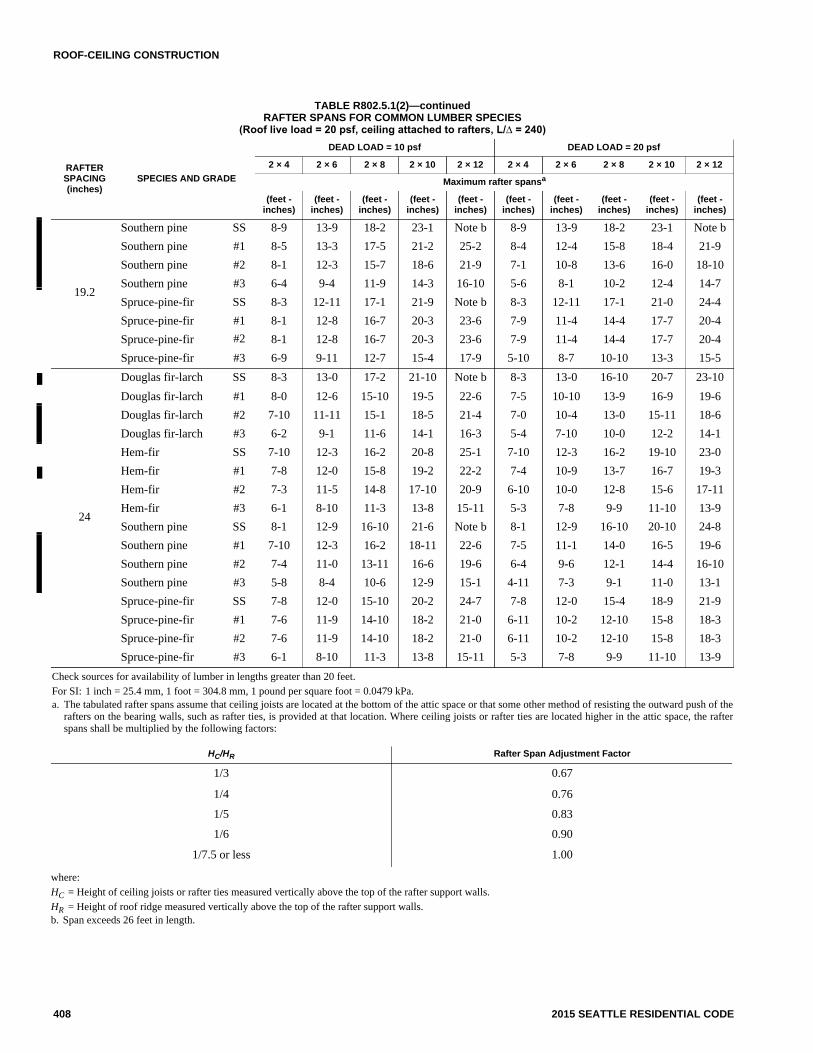
TABLE R802.5.1(7)RAFTER SPANS FOR 70 PSF GROUND SNOW LOAD
(Ceiling not attached to rafters, L/∆ = 180)
(continued)
RAFTERSPACING(inches)
SPECIES AND GRADE
DEAD LOAD = 10 psf DEAD LOAD = 20 psf
2 × 4 2 × 6 2 × 8 2 × 10 2 × 12 2 × 4 2 × 6 2 × 8 2 × 10 2 × 12
Maximum Rafter Spansa
(feet-inches)
(feet-inches)
(feet-inches)
(feet-inches)
(feet-inches)
(feet-inches)
(feet-inches)
(feet-inches)
(feet-inches)
(feet-inches)
12
Douglas fir-larch SS 7-7 11-10 15-8 19-9 22-10 7-7 11-10 15-3 18-7 21-7
Douglas fir-larch #1 7-1 10-5 13-2 16-1 18-8 6-8 9-10 12-5 15-2 17-7
Douglas fir-larch #2 6-9 9-10 12-6 15-3 17-9 6-4 9-4 11-9 14-5 16-8
Douglas fir-larch #3 5-2 7-7 9-7 11-8 13-6 4-10 7-1 9-0 11-0 12-9
Hem-fir SS 7-2 11-3 14-9 18-10 22-1 7-2 11-3 14-8 18-0 20-10
Hem-fir #1 7-0 10-3 13-0 15-11 18-5 6-7 9-8 12-3 15-0 17-5
Hem-fir #2 6-7 9-7 12-2 14-10 17-3 6-2 9-1 11-5 14-0 16-3
Hem-fir #3 5-0 7-4 9-4 11-5 13-2 4-9 6-11 8-9 10-9 12-5
Southern pine SS 7-5 11-8 15-4 19-7 23-7 7-5 11-8 15-4 18-10 22-3
Southern pine #1 7-1 10-7 13-5 15-9 18-8 6-9 10-0 12-8 14-10 17-7
Southern pine #2 6-1 9-2 11-7 13-9 16-2 5-9 8-7 10-11 12-11 15-3
Southern pine #3 4-8 6-11 8-9 10-7 12-6 4-5 6-6 8-3 10-0 11-10
Spruce-pine-fir SS 7-0 11-0 14-6 18-0 20-11 7-0 11-0 13-11 17-0 19-8
Spruce-pine-fir #1 6-8 9-9 12-4 15-1 17-6 6-3 9-2 11-8 14-2 16-6
Spruce-pine-fir #2 6-8 9-9 12-4 15-1 17-6 6-3 9-2 11-8 14-2 16-6
Spruce-pine-fir #3 5-0 7-4 9-4 11-5 13-2 4-9 6-11 8-9 10-9 12-5
16
Douglas fir-larch SS 6-10 10-9 14-0 17-1 19-10 6-10 10-5 13-2 16-1 18-8
Douglas fir-larch #1 6-2 9-0 11-5 13-11 16-2 5-10 8-6 10-9 13-2 15-3
Douglas fir-larch #2 5-10 8-7 10-10 13-3 15-4 5-6 8-1 10-3 12-6 14-6
Douglas fir-larch #3 4-6 6-6 8-3 10-1 11-9 4-3 6-2 7-10 9-6 11-1
Hem-fir SS 6-6 10-2 13-5 16-6 19-2 6-6 10-1 12-9 15-7 18-0
Hem-fir #1 6-1 8-11 11-3 13-9 16-0 5-9 8-5 10-8 13-0 15-1
Hem-fir #2 5-8 8-4 10-6 12-10 14-11 5-4 7-10 9-11 12-1 14-1
Hem-fir #3 4-4 6-4 8-1 9-10 11-5 4-1 6-0 7-7 9-4 10-9
Southern pine SS 6-9 10-7 14-0 17-4 20-5 6-9 10-7 13-9 16-4 19-3
Southern pine #1 6-2 9-2 11-8 13-8 16-2 5-10 8-8 11-0 12-10 15-3
Southern pine #2 5-3 7-11 10-0 11-11 14-0 5-0 7-5 9-5 11-3 13-2
Southern pine #3 4-1 6-0 7-7 9-2 10-10 3-10 5-8 7-1 8-8 10-3
Spruce-pine-fir SS 6-4 10-0 12-9 15-7 18-1 6-4 9-6 12-0 14-8 17-1
Spruce-pine-fir #1 5-9 8-5 10-8 13-1 15-2 5-5 7-11 10-1 12-4 14-3
Spruce-pine-fir #2 5-9 8-5 10-8 13-1 15-2 5-5 7-11 10-1 12-4 14-3
Spruce-pine-fir #3 4-4 6-4 8-1 9-10 11-5 4-1 6-0 7-7 9-4 10-9
19.2
Douglas fir-larch SS 6-6 10-1 12-9 15-7 18-1 6-6 9-6 12-0 14-8 17-1
Douglas fir-larch #1 5-7 8-3 10-5 12-9 14-9 5-4 7-9 9-10 12-0 13-11
Douglas fir-larch #2 5-4 7-10 9-11 12-1 14-0 5-0 7-4 9-4 11-5 13-2
Douglas fir-larch #3 4-1 6-0 7-7 9-3 10-8 3-10 5-7 7-1 8-8 10-1
Hem-fir SS 6-1 9-7 12-4 15-1 17-4 6-1 9-2 11-8 14-2 15-5
Hem-fir #1 5-7 8-2 10-3 12-7 14-7 5-3 7-8 9-8 11-10 13-9
Hem-fir #2 5-2 7-7 9-7 11-9 13-7 4-11 7-2 9-1 11-1 12-10
Hem-fir #3 4-0 5-10 7-4 9-0 10-5 3-9 5-6 6-11 8-6 9-10
ROOF-CEILING CONSTRUCTION
418 2015 SEATTLE RESIDENTIAL CODE
TABLE R802.5.1(7)—continuedRAFTER SPANS FOR 70 PSF GROUND SNOW LOAD
(Ceiling not attached to rafters, L/∆ = 180)
Check sources for availability of lumber in lengths greater than 20 feet.
For SI: 1 inch = 25.4 mm, 1 foot = 304.8 mm, 1 pound per square foot = 0.0479 kPa.
a. The tabulated rafter spans assume that ceiling joists are located at the bottom of the attic space or that some other method of resisting the outward push of therafters on the bearing walls, such as rafter ties, is provided at that location. Where ceiling joists or rafter ties are located higher in the attic space, the rafterspans shall be multiplied by the following factors:
RAFTERSPACING(inches)
SPECIES AND GRADE
DEAD LOAD = 10 psf DEAD LOAD = 20 psf
2 × 4 2 × 6 2 × 8 2 × 10 2 × 12 2 × 4 2 × 6 2 × 8 2 × 10 2 × 12
Maximum Rafter Spansa
(feet-inches)
(feet-inches)
(feet-inches)
(feet-inches)
(feet-inches)
(feet-inches)
(feet-inches)
(feet-inches)
(feet-inches)
(feet-inches)
19.2
Southern pine SS 6-4 10-0 13-2 15-10 18-8 6-4 9-10 12-6 14-11 17-7
Southern pine #1 5-8 8-5 10-8 12-5 14-9 5-4 7-11 10-0 11-9 13-11
Southern pine #2 4-10 7-3 9-2 10-10 12-9 4-6 6-10 8-8 10-3 12-1
Southern pine #3 3-8 5-6 6-11 8-4 9-11 3-6 5-2 6-6 7-11 9-4
Spruce-pine-fir SS 6-0 9-2 11-8 14-3 16-6 5-11 8-8 11-0 13-5 15-7
Spruce-pine-fir #1 5-3 7-8 9-9 11-11 13-10 5-0 7-3 9-2 11-3 13-0
Spruce-pine-fir #2 5-3 7-8 9-9 11-11 13-10 5-0 7-3 9-2 11-3 13-0
Spruce-pine-fir #3 4-0 5-10 7-4 9-0 10-5 3-9 5-6 6-11 8-6 9-10
24
Douglas fir-larch SS 6-0 9-0 11-5 13-11 16-2 5-10 8-6 10-9 13-2 15-3
Douglas fir-larch #1 5-0 7-4 9-4 11-5 13-2 4-9 6-11 8-9 10-9 12-5
Douglas fir-larch #2 4-9 7-0 8-10 10-10 12-6 4-6 6-7 8-4 10-2 11-10
Douglas fir-larch #3 3-8 5-4 6-9 8-3 9-7 3-5 5-0 6-4 7-9 9-10
Hem-fir SS 5-8 8-8 11-0 13-6 13-11 5-7 8-3 10-5 12-4 12-4
Hem-fir #1 5-0 7-3 9-2 11-3 13-0 4-8 6-10 8-8 10-7 12-4
Hem-fir #2 4-8 6-9 8-7 10-6 12-2 4-4 6-5 8-1 9-11 11-6
Hem-fir #3 3-7 5-2 6-7 8-1 9-4 3-4 4-11 6-3 7-7 8-10
Southern pine SS 5-11 9-3 11-11 14-2 16-8 5-11 8-10 11-2 13-4 15-9
Southern pine #1 5-0 7-6 9-6 11-1 13-2 4-9 7-1 9-0 10-6 12-5
Southern pine #2 4-4 6-5 8-2 9-9 11-5 4-1 6-1 7-9 9-2 10-9
Southern pine #3 3-4 4-11 6-2 7-6 8-10 3-1 4-7 5-10 7-1 8-4
Spruce-pine-fir SS 5-6 8-3 10-5 12-9 14-9 5-4 7-9 9-10 12-0 12-11
Spruce-pine-fir #1 4-8 6-11 8-9 10-8 12-4 4-5 6-6 8-3 10-0 11-8
Spruce-pine-fir #2 4-8 6-11 8-9 10-8 12-4 4-5 6-6 8-3 10-0 11-8
Spruce-pine-fir #3 3-7 5-2 6-7 8-1 9-4 3-4 4-11 6-3 7-7 8-10
where:
HC = Height of ceiling joists or rafter ties measured vertically above the top of the rafter support walls.
HR = Height of roof ridge measured vertically above the top of the rafter support walls.
HC/HR Rafter Span Adjustment Factor
1/3 0.67
1/4 0.76
1/5 0.83
1/6 0.90
1/7.5 or less 1.00

ROOF-CEILING CONSTRUCTION
2015 SEATTLE RESIDENTIAL CODE 419
TABLE R802.5.1(8)RAFTER SPANS FOR 70 PSF GROUND SNOW LOAD
(Ceiling attached to rafters, L/∆ = 240)
(continued)
RAFTERSPACING(inches)
SPECIES AND GRADE
DEAD LOAD = 10 psf DEAD LOAD = 20 psf
2 × 4 2 × 6 2 × 8 2 × 10 2 × 12 2 × 4 2 × 6 2 × 8 2 × 10 2 × 12
Maximum rafter spansa
(feet -inches)
(feet -inches)
(feet -inches)
(feet -inches)
(feet -inches)
(feet -inches)
(feet -inches)
(feet -inches)
(feet -inches)
(feet -inches)
12
Douglas fir-larch SS 6-10 10-9 14-3 18-2 22-1 6-10 10-9 14-3 18-2 21-7
Douglas fir-larch #1 6-7 10-5 13-2 16-1 18-8 6-7 9-10 12-5 15-2 17-7
Douglas fir-larch #2 6-6 9-10 12-6 15-3 17-9 6-4 9-4 11-9 14-5 16-8
Douglas fir-larch #3 5-2 7-7 9-7 11-8 13-6 4-10 7-1 9-0 11-0 12-9
Hem-fir SS 6-6 10-2 13-5 17-2 20-10 6-6 10-2 13-5 17-2 20-10
Hem-fir #1 6-4 10-0 13-0 15-11 18-5 6-4 9-8 12-3 15-0 17-5
Hem-fir #2 6-1 9-6 12-2 14-10 17-3 6-1 9-1 11-5 14-0 16-3
Hem-fir #3 5-0 7-4 9-4 11-5 13-2 4-9 6-11 8-9 10-9 12-5
Southern pine SS 6-9 10-7 14-0 17-10 21-8 6-9 10-7 14-0 17-10 21-8
Southern pine #1 6-6 10-2 13-5 15-9 18-8 6-6 10-0 12-8 14-10 17-7
Southern pine #2 6-1 9-2 11-7 13-9 16-2 5-9 8-7 10-11 12-11 15-3
Southern pine #3 4-8 6-11 8-9 10-7 12-6 4-5 6-6 8-3 10-0 11-10
Spruce-pine-fir SS 6-4 10-0 13-2 16-9 20-5 6-4 10-0 13-2 16-9 19-8
Spruce-pine-fir #1 6-2 9-9 12-4 15-1 17-6 6-2 9-2 11-8 14-2 16-6
Spruce-pine-fir #2 6-2 9-9 12-4 15-1 17-6 6-2 9-2 11-8 14-2 16-6
Spruce-pine-fir #3 5-0 7-4 9-4 11-5 13-2 4-9 6-11 8-9 10-9 12-5
16
Douglas fir-larch SS 6-3 9-10 12-11 16-6 19-10 6-3 9-10 12-11 16-1 18-8
Douglas fir-larch #1 6-0 9-0 11-5 13-11 16-2 5-10 8-6 10-9 13-2 15-3
Douglas fir-larch #2 5-10 8-7 10-10 13-3 15-4 5-6 8-1 10-3 12-6 14-6
Douglas fir-larch #3 4-6 6-6 8-3 10-1 11-9 4-3 6-2 7-10 9-6 11-1
Hem-fir SS 5-11 9-3 12-2 15-7 18-11 5-11 9-3 12-2 15-7 18-0
Hem-fir #1 5-9 8-11 11-3 13-9 16-0 5-9 8-5 10-8 13-0 15-1
Hem-fir #2 5-6 8-4 10-6 12-10 14-11 5-4 7-10 9-11 12-1 14-1
Hem-fir #3 4-4 6-4 8-1 9-10 11-5 4-1 6-0 7-7 9-4 10-9
Southern pine SS 6-1 9-7 12-8 16-2 19-8 6-1 9-7 12-8 16-2 19-3
Southern pine #1 5-11 9-2 11-8 13-8 16-2 5-10 8-8 11-0 12-10 15-3
Southern pine #2 5-3 7-11 10-0 11-11 14-0 5-0 7-5 9-5 11-3 13-2
Southern pine #3 4-1 6-0 7-7 9-2 10-10 3-10 5-8 7-1 8-8 10-3
Spruce-pine-fir SS 5-9 9-1 11-11 15-3 18-1 5-9 9-1 11-11 14-8 17-1
Spruce-pine-fir #1 5-8 8-5 10-8 13-1 15-2 5-5 7-11 10-1 12-4 14-3
Spruce-pine-fir #2 5-8 8-5 10-8 13-1 15-2 5-5 7-11 10-1 12-4 14-3
Spruce-pine-fir #3 4-4 6-4 8-1 9-10 11-5 4-1 6-0 7-7 9-4 10-9
19.2
Douglas fir-larch SS 5-10 9-3 12-2 15-6 18-1 5-10 9-3 12-0 14-8 17-1
Douglas fir-larch #1 5-7 8-3 10-5 12-9 14-9 5-4 7-9 9-10 12-0 13-11
Douglas fir-larch #2 5-4 7-10 9-11 12-1 14-0 5-0 7-4 9-4 11-5 13-2
Douglas fir-larch #3 4-1 6-0 7-7 9-3 10-8 3-10 5-7 7-1 8-8 10-1
Hem-fir SS 5-6 8-8 11-6 14-8 17-4 5-6 8-8 11-6 14-2 15-5
Hem-fir #1 5-5 8-2 10-3 12-7 14-7 5-3 7-8 9-8 11-10 13-9
Hem-fir #2 5-2 7-7 9-7 11-9 13-7 4-11 7-2 9-1 11-1 12-10
Hem-fir #3 4-0 5-10 7-4 9-0 10-5 3-9 5-6 6-11 8-6 9-10

ROOF-CEILING CONSTRUCTION
420 2015 SEATTLE RESIDENTIAL CODE
TABLE R802.5.1(8)—continuedRAFTER SPANS FOR 70 PSF GROUND SNOW LOAD
(Ceiling attached to rafters, L/∆ = 240)
Check sources for availability of lumber in lengths greater than 20 feet.
For SI: 1 inch = 25.4 mm, 1 foot = 304.8 mm, 1 pound per square foot = 0.0479 kPa.
a. The tabulated rafter spans assume that ceiling joists are located at the bottom of the attic space or that some other method of resisting the outward push of therafters on the bearing walls, such as rafter ties, is provided at that location. Where ceiling joists or rafter ties are located higher in the attic space, the rafterspans shall be multiplied by the following factors:
RAFTERSPACING(inches)
SPECIES AND GRADE
DEAD LOAD = 10 psf DEAD LOAD = 20 psf
2 × 4 2 × 6 2 × 8 2 × 10 2 × 12 2 × 4 2 × 6 2 × 8 2 × 10 2 × 12
Maximum rafter spansa
(feet -inches)
(feet -inches)
(feet -inches)
(feet -inches)
(feet -inches)
(feet -inches)
(feet -inches)
(feet -inches)
(feet -inches)
(feet -inches)
19.2
Southern pine SS 5-9 9-1 11-11 15-3 18-6 5-9 9-1 11-11 14-11 17-7
Southern pine #1 5-6 8-5 10-8 12-5 14-9 5-4 7-11 10-0 11-9 13-11
Southern pine #2 4-10 7-3 9-2 10-10 12-9 4-6 6-10 8-8 10-3 12-1
Southern pine #3 3-8 5-6 6-11 8-4 9-11 3-6 5-2 6-6 7-11 9-4
Spruce-pine-fir SS 5-5 8-6 11-3 14-3 16-6 5-5 8-6 11-0 13-5 15-7
Spruce-pine-fir #1 5-3 7-8 9-9 11-11 13-10 5-0 7-3 9-2 11-3 13-0
Spruce-pine-fir #2 5-3 7-8 9-9 11-11 13-10 5-0 7-3 9-2 11-3 13-0
Spruce-pine-fir #3 4-0 5-10 7-4 9-0 10-5 3-9 5-6 6-11 8-6 9-10
24
Douglas fir-larch SS 5-5 8-7 11-3 13-11 16-2 5-5 8-6 10-9 13-2 15-3
Douglas fir-larch #1 5-0 7-4 9-4 11-5 13-2 4-9 6-11 8-9 10-9 12-5
Douglas fir-larch #2 4-9 7-0 8-10 10-10 12-6 4-6 6-7 8-4 10-2 11-10
Douglas fir-larch #3 3-8 5-4 6-9 8-3 9-7 3-5 5-0 6-4 7-9 9-0
Hem-fir SS 5-2 8-1 10-8 13-6 13-11 5-2 8-1 10-5 12-4 12-4
Hem-fir #1 5-0 7-3 9-2 11-3 13-0 4-8 6-10 8-8 10-7 12-4
Hem-fir #2 4-8 6-9 8-7 10-6 12-2 4-4 6-5 8-1 9-11 11-6
Hem-fir #3 3-7 5-2 6-7 8-1 9-4 3-4 4-11 6-3 7-7 8-10
Southern pine SS 5-4 8-5 11-1 14-2 16-8 5-4 8-5 11-1 13-4 15-9
Southern pine #1 5-0 7-6 9-6 11-1 13-2 4-9 7-1 9-0 10-6 12-5
Southern pine #2 4-4 6-5 8-2 9-9 11-5 4-1 6-1 7-9 9-2 10-9
Southern pine #3 3-4 4-11 6-2 7-6 8-10 3-1 4-7 5-10 7-1 8-4
Spruce-pine-fir SS 5-0 7-11 10-5 12-9 14-9 5-0 7-9 9-10 12-0 12-11
Spruce-pine-fir #1 4-8 6-11 8-9 10-8 12-4 4-5 6-6 8-3 10-0 11-8
Spruce-pine-fir #2 4-8 6-11 8-9 10-8 12-4 4-5 6-6 8-3 10-0 11-8
Spruce-pine-fir #3 3-7 5-2 6-7 8-1 9-4 3-4 4-11 6-3 7-7 8-10
where:
HC = Height of ceiling joists or rafter ties measured vertically above the top of the rafter support walls.
HR = Height of roof ridge measured vertically above the top of the rafter support walls.
HC/HR Rafter Span Adjustment Factor
1/3 0.67
1/4 0.76
1/5 0.83
1/6 0.90
1/7.5 or less 1.00

ROOF-CEILING CONSTRUCTION
2015 SEATTLE RESIDENTIAL CODE 421
TABLE R802.5.1(9)RAFTER/CEILING JOIST HEEL JOINT CONNECTIONSa, b, c, d, e, f, h
For SI: 1 inch = 25.4 mm, 1 foot = 304.8 mm, 1 pound per square foot = 0.0479 kPa.
a. 40d box nails shall be permitted to be substituted for 16d common nails.
b. Nailing requirements shall be permitted to be reduced 25 percent if nails are clinched.
c. Heel joint connections are not required where the ridge is supported by a load-bearing wall, header or ridge beam.
d. Where intermediate support of the rafter is provided by vertical struts or purlins to a load-bearing wall, the tabulated heel joint connection requirements shallbe permitted to be reduced proportionally to the reduction in span.
e. Equivalent nailing patterns are required for ceiling joist to ceiling joist lap splices.
f. Where rafter ties are substituted for ceiling joists, the heel joint connection requirement shall be taken as the tabulated heel joint connection requirement fortwo-thirds of the actual rafter slope.
g. Applies to roof live load of 20 psf or less.
h. Tabulated heel joint connection requirements assume that ceiling joists or rafter ties are located at the bottom of the attic space. Where ceiling joists or rafterties are located higher in the attic, heel joint connection requirements shall be increased by the following factors:
RAFTERSLOPE
RAFTERSPACING(inches)
GROUND SNOW LOAD (psf)
20g 30 50 70
Roof span (feet)
12 20 28 36 12 20 28 36 12 20 28 36 12 20 28 36
Required number of 16d common nailsa, b per heel joint splicesc, d, e, f
3:12
12 4 6 8 10 4 6 8 11 5 8 12 15 6 11 15 20
16 5 8 10 13 5 8 11 14 6 11 15 20 8 14 20 26
24 7 11 15 19 7 11 16 21 9 16 23 30 12 21 30 39
4:12
12 3 5 6 8 3 5 6 8 4 6 9 11 5 8 12 15
16 4 6 8 10 4 6 8 11 5 8 12 15 6 11 15 20
24 5 8 12 15 5 9 12 16 7 12 17 22 9 16 23 29
5:12
12 3 4 5 6 3 4 5 7 3 5 7 9 4 7 9 12
16 3 5 6 8 3 5 7 9 4 7 9 12 5 9 12 16
24 4 7 9 12 4 7 10 13 6 10 14 18 7 13 18 23
7:12
12 3 4 4 5 3 3 4 5 3 4 5 7 3 5 7 9
16 3 4 5 6 3 4 5 6 3 5 7 9 4 6 9 11
24 3 5 7 9 3 5 7 9 4 7 10 13 5 9 13 17
9:12
12 3 3 4 4 3 3 3 4 3 3 4 5 3 4 5 7
16 3 4 4 5 3 3 4 5 3 4 5 7 3 5 7 9
24 3 4 6 7 3 4 6 7 3 6 8 10 4 7 10 13
12:12
12 3 3 3 3 3 3 3 3 3 3 3 4 3 3 4 5
16 3 3 4 4 3 3 3 4 3 3 4 5 3 4 5 7
24 3 4 4 5 3 3 4 6 3 4 6 8 3 6 8 10
where:
HC = Height of ceiling joists or rafter ties measured vertically above the top of the rafter support walls.
HR = Height of roof ridge measured vertically above the top of the rafter support walls.
HC/HR Heel Joint Connection Adjustment Factor
1/3 1.5
1/4 1.33
1/5 1.25
1/6 1.2
1/10 or less 1.11

ROOF-CEILING CONSTRUCTION
422 2015 SEATTLE RESIDENTIAL CODE
R802.6 Bearing. The ends of each rafter or ceiling joist shallhave not less than 11/2 inches (38 mm) of bearing on wood ormetal and not less than 3 inches (76 mm) on masonry or con-crete. The bearing on masonry or concrete shall be direct, or asill plate of 2-inch (51 mm) minimum nominal thickness shallbe provided under the rafter or ceiling joist. The sill plate shallprovide a minimum nominal bearing area of 48 square inches(30 865 mm2).
R802.6.1 Finished ceiling material. If the finished ceilingmaterial is installed on the ceiling prior to the attachment ofthe ceiling to the walls, such as in construction at a factory,a compression strip of the same thickness as the finishedceiling material shall be installed directly above the topplate of bearing walls if the compressive strength of the fin-ished ceiling material is less than the loads it will berequired to withstand. The compression strip shall cover theentire length of such top plate and shall be not less than one-half the width of the top plate. It shall be of material capableof transmitting the loads transferred through it.
R802.7 Cutting, drilling and notching. Structural roofmembers shall not be cut, bored or notched in excess of thelimitations specified in this section.
R802.7.1 Sawn lumber. Cuts, notches and holes in solidlumber joists, rafters, blocking and beams shall complywith the provisions of Section R502.8.1 except that canti-levered portions of rafters shall be permitted in accordancewith Section R802.7.1.1.
R802.7.1.1 Cantilevered portions of rafters. Notcheson cantilevered portions of rafters are permitted pro-vided the dimension of the remaining portion of the raf-ter is not less than 31/2 inches (89 mm) and the lengthof the cantilever does not exceed 24 inches (610 mm) inaccordance with Figure R802.7.1.1.
R802.7.1.2 Ceiling joist taper cut. Taper cuts at theends of the ceiling joist shall not exceed one-fourth thedepth of the member in accordance with FigureR802.7.1.2.
R802.7.2 Engineered wood products. Cuts, notches andholes bored in trusses, structural composite lumber, struc-tural glue-laminated members, cross-laminated timbermembers or I-joists are prohibited except where permittedby the manufacturer’s recommendations or where theeffects of such alterations are specifically considered in thedesign of the member by a registered design professional.
For SI: 1 inch = 25.4 mm, 1 foot = 305 mm, 1 degree = 0.018 rad.
Note: Where ceiling joists run perpendicular to the rafter, rafter ties shall be installed in accordance with Section R802.3.1.
HC = Height of ceiling joists or rafter ties measured vertically above the top of rafter support walls.
HR = Height of roof ridge measured vertically above the top of the rafter support walls.
FIGURE R802.5.1BRACED RAFTER CONSTRUCTION

ROOF-CEILING CONSTRUCTION
2015 SEATTLE RESIDENTIAL CODE 423
For SI: 1 inch = 25.4 mm.
FIGURE R802.7.1.1RAFTER NOTCH
FIGURE R802.7.1.2CEILING JOIST TAPER CUT

ROOF-CEILING CONSTRUCTION
424 2015 SEATTLE RESIDENTIAL CODE
R802.8 Lateral support. Roof framing members and ceilingjoists having a depth-to-thickness ratio exceeding 5 to 1based on nominal dimensions shall be provided with lateralsupport at points of bearing to prevent rotation. For roof raf-ters with ceiling joists attached in accordance with TableR602.3(1), the depth-to-thickness ratio for the total assemblyshall be determined using the combined thickness of the raf-ter plus the attached ceiling joist.
Exception: Roof trusses shall be braced in accordancewith Section R802.10.3.
R802.8.1 Bridging. Rafters and ceiling joists having adepth-to-thickness ratio exceeding 6 to 1 based on nominaldimensions shall be supported laterally by solid blocking,diagonal bridging (wood or metal) or a continuous 1-inch by3-inch (25 mm by 76 mm) wood strip nailed across the raf-ters or ceiling joists at intervals not exceeding 8 feet (2438mm).
R802.9 Framing of openings. Openings in roof and ceilingframing shall be framed with header and trimmer joists. Wherethe header joist span does not exceed 4 feet (1219 mm), theheader joist shall be permitted to be a single member the samesize as the ceiling joist or rafter. Single trimmer joists shall bepermitted to be used to carry a single header joist that is locatedwithin 3 feet (914 mm) of the trimmer joist bearing. Where theheader joist span exceeds 4 feet (1219 mm), the trimmer joistsand the header joist shall be doubled and of sufficient crosssection to support the ceiling joists or rafter framing into theheader. Approved hangers shall be used for the header joist totrimmer joist connections where the header joist span exceeds6 feet (1829 mm). Tail joists over 12 feet (3658 mm) long shallbe supported at the header by framing anchors or on ledgerstrips not less than 2 inches by 2 inches (51 mm by 51 mm).
R802.10 Wood trusses.
R802.10.1 Truss design drawings. Truss design draw-ings, prepared in conformance to Section R802.10.1, shallbe provided to the building official and approved prior toinstallation. Truss design drawings shall be provided withthe shipment of trusses delivered to the job site. Trussdesign drawings shall include, at a minimum, the follow-ing information:
1. Slope or depth, span and spacing.
2. Location of all joints.
3. Required bearing widths.
4. Design loads as applicable.
4.1. Top chord live load (as determined fromSection R301.6).
4.2. Top chord dead load.
4.3. Bottom chord live load.
4.4. Bottom chord dead load.
4.5. Concentrated loads and their points of appli-cation.
4.6. Controlling wind and earthquake loads.
5. Adjustments to lumber and joint connector designvalues for conditions of use.
6. Each reaction force and direction.
7. Joint connector type and description such as size,thickness or gage and the dimensioned location ofeach joint connector except where symmetricallylocated relative to the joint interface.
8. Lumber size, species and grade for each member.
9. Connection requirements for:
9.1. Truss to girder-truss.
9.2. Truss ply to ply.
9.3. Field splices.
10. Calculated deflection ratio and/or maximumdescription for live and total load.
11. Maximum axial compression forces in the trussmembers to enable the building designer to designthe size, connections and anchorage of the perma-nent continuous lateral bracing. Forces shall beshown on the truss design drawing or on supple-mental documents.
12. Required permanent truss member bracing location.
R802.10.2 Design. Wood trusses shall be designed inaccordance with accepted engineering practice. The designand manufacture of metal-plate-connected wood trussesshall comply with ANSI/TPI 1. The truss design drawingsshall be prepared by a registered professional whererequired by the statutes of the jurisdiction in which the proj-ect is to be constructed in accordance with Section R106.1.
R802.10.2.1 Applicability limits. The provisions ofthis section shall control the design of truss roofframing when snow controls for buildings, notgreater than 60 feet (18 288 mm) in length perpen-dicular to the joist, rafter or truss span, not greaterthan 36 feet (10 973 mm) in width parallel to thejoist, rafter or truss span, not more than three storiesabove grade plane in height, and roof slopes notsmaller than 3:12 (25 percent slope) or greater than12:12 (100-percent slope). Truss roof framing con-structed in accordance with the provisions of thissection shall be limited to sites subjected to a maxi-mum design wind speed of 140 miles per hour (63 m/s), Exposure B or C, and a maximum ground snowload of 70 psf (3352 Pa). For consistent loading ofall truss types, roof snow load is to be computed as:0.7 pg.
R802.10.3 Bracing. Trusses shall be braced to preventrotation and provide lateral stability in accordance with therequirements specified in the construction documents forthe building and on the individual truss design drawings. Inthe absence of specific bracing requirements, trusses shallbe braced in accordance with accepted industry practicesuch as the SBCA Building Component Safety Information(BCSI) Guide to Good Practice for Handling, Installing &Bracing of Metal Plate Connected Wood Trusses.
R802.10.4 Alterations to trusses. Truss members shall notbe cut, notched, drilled, spliced or otherwise altered in anyway without the approval of a registered design professional.Alterations resulting in the addition of load such as HVACequipment water heater that exceeds the design load for the
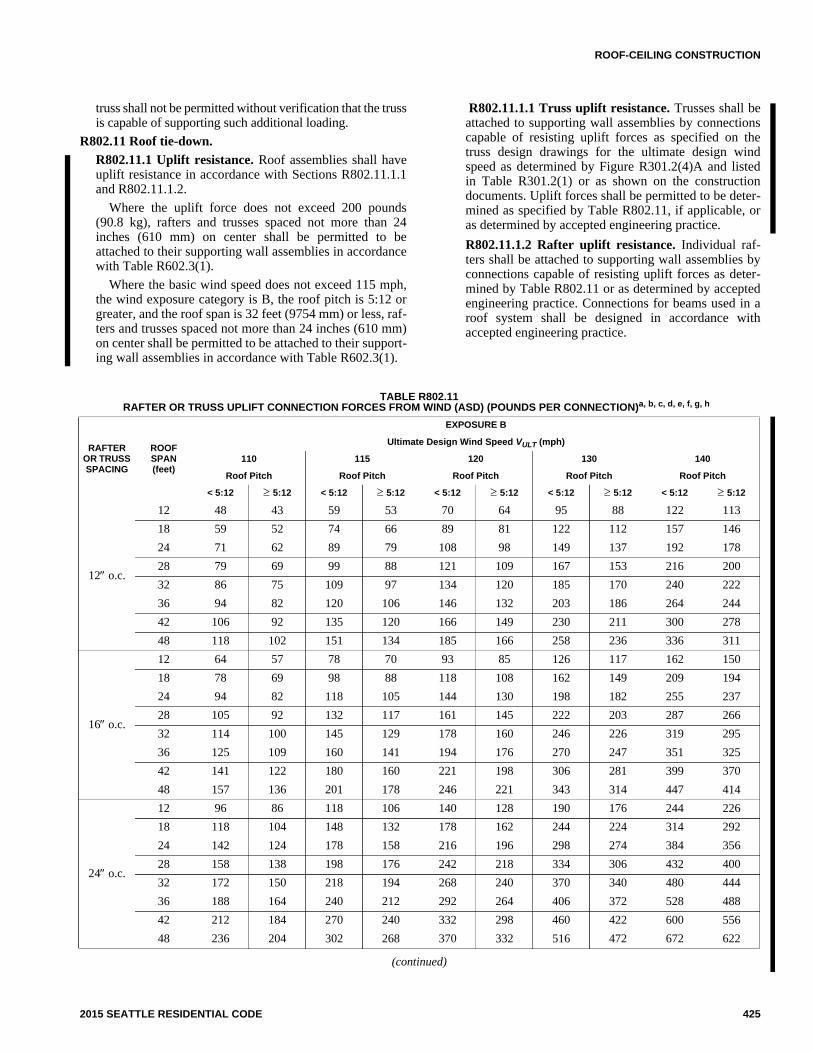
ROOF-CEILING CONSTRUCTION
2015 SEATTLE RESIDENTIAL CODE 425
truss shall not be permitted without verification that the trussis capable of supporting such additional loading.
R802.11 Roof tie-down.
R802.11.1 Uplift resistance. Roof assemblies shall haveuplift resistance in accordance with Sections R802.11.1.1and R802.11.1.2.
Where the uplift force does not exceed 200 pounds(90.8 kg), rafters and trusses spaced not more than 24inches (610 mm) on center shall be permitted to beattached to their supporting wall assemblies in accordancewith Table R602.3(1).
Where the basic wind speed does not exceed 115 mph,the wind exposure category is B, the roof pitch is 5:12 orgreater, and the roof span is 32 feet (9754 mm) or less, raf-ters and trusses spaced not more than 24 inches (610 mm)on center shall be permitted to be attached to their support-ing wall assemblies in accordance with Table R602.3(1).
R802.11.1.1 Truss uplift resistance. Trusses shall beattached to supporting wall assemblies by connectionscapable of resisting uplift forces as specified on thetruss design drawings for the ultimate design windspeed as determined by Figure R301.2(4)A and listedin Table R301.2(1) or as shown on the constructiondocuments. Uplift forces shall be permitted to be deter-mined as specified by Table R802.11, if applicable, oras determined by accepted engineering practice.
R802.11.1.2 Rafter uplift resistance. Individual raf-ters shall be attached to supporting wall assemblies byconnections capable of resisting uplift forces as deter-mined by Table R802.11 or as determined by acceptedengineering practice. Connections for beams used in aroof system shall be designed in accordance withaccepted engineering practice.
TABLE R802.11RAFTER OR TRUSS UPLIFT CONNECTION FORCES FROM WIND (ASD) (POUNDS PER CONNECTION)a, b, c, d, e, f, g, h
(continued)
RAFTEROR TRUSSSPACING
ROOFSPAN(feet)
EXPOSURE B
Ultimate Design Wind Speed VULT (mph)
110 115 120 130 140
Roof Pitch Roof Pitch Roof Pitch Roof Pitch Roof Pitch
< 5:12 5:12 < 5:12 5:12 < 5:12 5:12 < 5:12 5:12 < 5:12 5:12
12 o.c.
12 48 43 59 53 70 64 95 88 122 113
18 59 52 74 66 89 81 122 112 157 146
24 71 62 89 79 108 98 149 137 192 178
28 79 69 99 88 121 109 167 153 216 200
32 86 75 109 97 134 120 185 170 240 222
36 94 82 120 106 146 132 203 186 264 244
42 106 92 135 120 166 149 230 211 300 278
48 118 102 151 134 185 166 258 236 336 311
16 o.c.
12 64 57 78 70 93 85 126 117 162 150
18 78 69 98 88 118 108 162 149 209 194
24 94 82 118 105 144 130 198 182 255 237
28 105 92 132 117 161 145 222 203 287 266
32 114 100 145 129 178 160 246 226 319 295
36 125 109 160 141 194 176 270 247 351 325
42 141 122 180 160 221 198 306 281 399 370
48 157 136 201 178 246 221 343 314 447 414
24 o.c.
12 96 86 118 106 140 128 190 176 244 226
18 118 104 148 132 178 162 244 224 314 292
24 142 124 178 158 216 196 298 274 384 356
28 158 138 198 176 242 218 334 306 432 400
32 172 150 218 194 268 240 370 340 480 444
36 188 164 240 212 292 264 406 372 528 488
42 212 184 270 240 332 298 460 422 600 556
48 236 204 302 268 370 332 516 472 672 622

ROOF-CEILING CONSTRUCTION
426 2015 SEATTLE RESIDENTIAL CODE
TABLE R802.11—continuedRAFTER OR TRUSS UPLIFT CONNECTION FORCES FROM WIND (POUNDS PER CONNECTION)a, b, c, d, e, f, g, h
For SI: 1 inch = 25.4 mm, 1 foot = 304.8 mm, 1 mile per hour = 0.447 m/s, 1 pound = 0.454 kg, 1 pound per square foot = 47.9 N/m2, 1 plf = 14.6 N/m.
a. The uplift connection forces are based on a maximum 33-foot mean roof height and Wind Exposure Category B or C. For Exposure D, the uplift connectionforce shall be selected from the Exposure C portion of the table using the next highest tabulated ultimate design wind speed. The adjustment coefficients inTable R301.2(3) shall not be used to multiply the tabulated forces for Exposures C and D or for other mean roof heights.
b. The uplift connection forces include an allowance for roof and ceiling assembly dead load of 15 psf.
c. The tabulated uplift connection forces are limited to a maximum roof overhang of 24 inches.
d. The tabulated uplift connection forces shall be permitted to be multiplied by 0.75 for connections not located within 8 feet of building corners.
e. For buildings with hip roofs with 5:12 and greater pitch, the tabulated uplift connection forces shall be permitted to be multiplied by 0.70. This reduction shallnot be combined with any other reduction in tabulated forces.
f. For wall-to-wall and wall-to-foundation connections, the uplift connection force shall be permitted to be reduced by 60 plf for each full wall above.
g. Linear interpolation between tabulated roof spans and wind speeds shall be permitted.
h. The tabulated forces for a 12-inch on-center spacing shall be permitted to be used to determine the uplift load in pounds per linear foot.
RAFTEROR TRUSSSPACING
ROOFSPAN(feet)
EXPOSURE C
Ultimate Design Wind Speed VULT (mph)
110 115 120 130 140
Roof Pitch Roof Pitch Roof Pitch Roof Pitch Roof Pitch
< 5:12 5:12 < 5:12 5:12 < 5:12 5:12 < 5:12 5:12 < 5:12 5:12
12 o.c.
12 95 88 110 102 126 118 161 151 198 186
18 121 111 141 131 163 151 208 195 257 242
24 148 136 173 160 200 185 256 239 317 298
28 166 152 195 179 225 208 289 269 358 335
32 184 168 216 199 249 231 321 299 398 373
36 202 185 237 219 274 254 353 329 438 411
42 229 210 269 248 312 289 402 375 499 468
48 256 234 302 278 349 323 450 420 560 524
16 o.c.
12 126 117 146 136 168 157 214 201 263 247
18 161 148 188 174 217 201 277 259 342 322
24 197 181 230 213 266 246 340 318 422 396
28 221 202 259 238 299 277 384 358 476 446
32 245 223 287 265 331 307 427 398 529 496
36 269 246 315 291 364 338 469 438 583 547
42 305 279 358 330 415 384 535 499 664 622
48 340 311 402 370 464 430 599 559 745 697
24 o.c.
12 190 176 220 204 252 236 322 302 396 372
18 242 222 282 262 326 302 416 390 514 484
24 296 272 346 320 400 370 512 478 634 596
28 332 304 390 358 450 416 578 538 716 670
32 368 336 432 398 498 462 642 598 796 746
36 404 370 474 438 548 508 706 658 876 822
42 458 420 538 496 624 578 804 750 998 936
48 512 468 604 556 698 646 900 840 1120 1048

ROOF-CEILING CONSTRUCTION
2015 SEATTLE RESIDENTIAL CODE 427
SECTION R803ROOF SHEATHING
R803.1 Lumber sheathing. Allowable spans for lumberused as roof sheathing shall conform to Table R803.1. Spacedlumber sheathing for wood shingle and shake roofing shallconform to the requirements of Sections R905.7 and R905.8.Spaced lumber sheathing is not allowed in Seismic DesignCategory D2.
TABLE R803.1MINIMUM THICKNESS OF LUMBER ROOF SHEATHING
For SI: 1 inch = 25.4 mm.
a. Minimum 270 Fb, 340,000 E.
b. Minimum 420 Fb, 660,000 E.
c. Minimum 600Fb, 1,150,000 E.
R803.2 Wood structural panel sheathing.
R803.2.1 Identification and grade. Wood structural pan-els shall conform to DOC PS 1, DOC PS 2, CSA O437 orCSA O325, and shall be identified for grade, bond classifi-cation and performance category by a grade mark or certif-icate of inspection issued by an approved agency. Woodstructural panels shall comply with the grades specified inTable R503.2.1.1(1).
R803.2.1.1 Exposure durability. Wood structural pan-els, when designed to be permanently exposed in out-door applications, shall be of an exterior exposuredurability. Wood structural panel roof sheathingexposed to the underside shall be permitted to be of inte-rior type bonded with exterior glue, identified as Expo-sure 1.
R803.2.1.2 Fire-retardant-treated plywood. Theallowable unit stresses for fire-retardant-treated ply-wood, including fastener values, shall be developedfrom an approved method of investigation that consid-ers the effects of anticipated temperature and humidityto which the fire-retardant-treated plywood will be sub-jected, the type of treatment and redrying process. Thefire-retardant-treated plywood shall be graded by anapproved agency.
R803.2.2 Allowable spans. The maximum allowablespans for wood structural panel roof sheathing shall notexceed the values set forth in Table R503.2.1.1(1), or APAE30.
R803.2.3 Installation. Wood structural panel used as roofsheathing shall be installed with joints staggered or notstaggered in accordance with Table R602.3(1), APA E30for wood roof framing or with Table R804.3 for cold-formed steel roof framing.
SECTION R804COLD-FORMED STEEL ROOF FRAMING
R804.1 General. Elements shall be straight and free of anydefects that would significantly affect their structural perfor-mance. Cold-formed steel roof framing members shall be inaccordance with the requirements of this section.
R804.1.1 Applicability limits. The provisions of this sec-tion shall control the construction of cold-formed steelroof framing for buildings not greater than 60 feet (18 288mm) perpendicular to the joist, rafter or truss span, notgreater than 40 feet (12 192 mm) in width parallel to thejoist span or truss, less than or equal to three stories abovegrade plane and with roof slopes not less than 3:12 (25-percent slope) or greater than 12:12 (100-percent slope).Cold-formed steel roof framing constructed in accordancewith the provisions of this section shall be limited to siteswhere the ultimate design wind speed is less than 139miles per hour (62 m/s), Exposure Category B or C, andthe ground snow load is less than or equal to 70 poundsper square foot (3350 Pa).
R804.1.2 In-line framing. Cold-formed steel roof fram-ing constructed in accordance with Section R804 shall belocated in line with load-bearing studs in accordance withFigure R804.1.2 and the tolerances specified as follows:
1. The maximum tolerance shall be 3/4 inch (19.1 mm)between the centerline of the horizontal framingmember and the centerline of the vertical framingmember.
2. Where the centerline of the horizontal framingmember and bearing stiffener are located to one sideof the centerline of the vertical framing member, themaximum tolerance shall be 1/8 inch (3.2 mm)between the web of the horizontal framing memberand the edge of the vertical framing member.
R804.2 Structural framing. Load-bearing, cold-formed steelroof framing members shall be in accordance with this section.
R804.2.1 Material. Load-bearing, cold-formed steelframing members shall be cold formed to shape fromstructural quality sheet steel complying with the require-ments of ASTM A 1003, Structural Grades 33 Type H and50 Type H.
R804.2.2 Corrosion protection. Load-bearing, cold-formed steel framing shall have a metallic coating comply-ing with ASTM A 1003 and one of the following:
1. A minimum of G 60 in accordance with ASTM A653.
2. A minimum of AZ 50 in accordance with ASTM A792.
R804.2.3 Dimension, thickness and material grade.Load-bearing, cold-formed steel roof framing membersshall comply with Figure R804.2.3(1) and with the dimen-sional and thickness requirements specified in TableR804.2.3. Additionally, C-shaped sections shall have aminimum flange width of 1.625 inches (41 mm) and amaximum flange width of 2 inches (51 mm). The mini-mum lip size for C-shaped sections shall be 1/2 inch (12.7
RAFTER OR BEAM SPACING
(inches)
MINIMUM NET THICKNESS
(inches)
24 5/8
48a
11/2 T & G60b
72c

ROOF-CEILING CONSTRUCTION
428 2015 SEATTLE RESIDENTIAL CODE
mm). Tracks shall comply with Figure R804.2.3(2) andshall have a minimum flange width of 11/4 inches (32mm). Minimum Grade 33 ksi steel shall be used wherever33 mil and 43 mil thicknesses are specified. MinimumGrade 50 ksi steel shall be used wherever 54 and 68 milthicknesses are specified.
R804.2.4 Identification. Load-bearing, cold-formed steelframing members shall have a legible label, stencil, stampor embossment with the following information as a mini-mum:
1. Manufacturer’s identification.
2. Minimum base steel thickness in inches (mm).
3. Minimum coating designation.
4. Minimum yield strength, in kips per square inch(ksi) (MPa).
R804.2.5 Fastening requirements. Screws for steel-to-steel connections shall be installed with a minimum edgedistance and center-to-center spacing of 1/2 inch (12.7mm), shall be self-drilling tapping and shall conform toASTM C 1513. Structural sheathing shall be attached tocold-formed steel roof rafters with minimum No. 8 self-drilling tapping screws that conform to ASTM C 1513.Screws for attaching structural sheathing to cold-formedsteel roof framing shall have a minimum head diameter of0.292 inch (7.4 mm) with countersunk heads and shall beinstalled with a minimum edge distance of 3/8 inch (9.5mm). Gypsum board ceilings shall be attached to cold-
formed steel joists with minimum No. 6 screws conform-ing to ASTM C 954 or ASTM C 1513 with a bugle-headstyle and shall be installed in accordance with SectionR805. For all connections, screws shall extend through thesteel a minimum of three exposed threads. Fasteners shallhave rust-inhibitive coating suitable for the installation inwhich they are being used, or be manufactured from mate-rial not susceptible to corrosion.
R804.2.6 Web holes, web hole reinforcing and web holepatching. Web holes, web hole reinforcing and web holepatching shall be in accordance with this section.
R804.2.6.1 Web holes. Web holes in roof framingmembers shall comply with all of the following condi-tions:
1. Holes shall conform to Figure R804.2.6.1.
2. Holes shall be permitted only along the centerlineof the web of the framing member.
3. Center-to-center spacing of holes shall not be lessthan 24 inches (610 mm).
4. The web hole width shall be not greater than one-half the member depth, or 21/2 inches (64 mm).
5. Holes shall have a web hole length not exceeding41/2 inches (114 mm).
6. The minimum distance between the edge of thebearing surface and the edge of the web hole shallbe not less than 10 inches (254 mm).
For SI: 1 inch = 25.4 mm.
FIGURE R804.1.2IN-LINE FRAMING

ROOF-CEILING CONSTRUCTION
2015 SEATTLE RESIDENTIAL CODE 429
Framing members with web holes not conformingto Items 1 though 6 shall be reinforced in accordancewith Section R804.2.6.2, patched in accordance withSection R804.2.6.3 or designed in accordance withaccepted engineering practices.
R804.2.6.2 Web hole reinforcing. Reinforcement ofweb holes in ceiling joists not conforming to therequirements of Section R804.2.6.1 shall be permittedif the hole is located fully within the center 40 percentof the span and the depth and length of the hole do notexceed 65 percent of the flat width of the web. Thereinforcing shall be a steel plate or C-shaped sectionwith a hole that does not exceed the web hole size lim-itations of Section R804.2.6.1 for the member beingreinforced. The steel reinforcing shall be the same
thickness as the receiving member and shall extend notless than 1 inch (25 mm) beyond all edges of the hole.The steel reinforcing shall be fastened to the web of thereceiving member with No. 8 screws spaced not greaterthan 1 inch (25 mm) center to center along the edges ofthe patch with minimum edge distance of 1/2 inch (12.7mm).
R804.2.6.3 Hole patching. Patching of web holes inroof framing members not conforming to the require-ments in Section R804.2.6.1 shall be permitted inaccordance with either of the following methods:
1. Framing members shall be replaced or designedin accordance with accepted engineering prac-tices where web holes exceed either of the fol-lowing size limits:
TABLE R804.2.3LOAD-BEARING COLD-FORMED STEEL ROOF FRAMING MEMBER SIZES AND THICKNESSES
For SI: 1 inch = 25.4 mm
a. The member designation is defined by the first number representing the member depth in hundredths of an inch, the letter “s” representing a stud or joistmember, the second number representing the flange width in hundredths of an inch and the letter “t” shall be a number representing the minimum base metalthickness in mils.
MEMBERDESIGNATIONa
WEB DEPTH(inches)
MINIMUM BASE STEEL THICKNESSmil (inches)
350S162-t 3.5 33 (0.0329), 43 (0.0428), 54 (0.0538)
550S162-t 5.5 33 (0.0329), 43 (0.0428), 54 (0.0538), 68 (0.0677)
800S162-t 8 33 (0.0329), 43 (0.0428), 54 (0.0538), 68 (0.0677)
1000S162-t 10 43 (0.0428), 54 (0.0538), 68 (0.0677)
1200S162-t 12 43 (0.0428), 54 (0.0538), 68 (0.0677)
FIGURE R804.2.3(1)C-SHAPED SECTION
FIGURE R804.2.3(2)TRACK SECTION

ROOF-CEILING CONSTRUCTION
430 2015 SEATTLE RESIDENTIAL CODE
1.1. The depth of the hole, measured acrossthe web, exceeds 70 percent of the flatwidth of the web.
1.2. The length of the hole measured alongthe web, exceeds 10 inches (254 mm) orthe depth of the web, whichever isgreater.
2. Web holes not exceeding the dimensional require-ments in Section R804.2.6.3, Item 1, shall bepatched with a solid steel plate, stud section or tracksection in accordance with Figure R804.2.6.3. Thesteel patch shall, as a minimum, be the same thick-ness as the receiving member and shall extend notless than 1 inch (25 mm) beyond all edges of thehole. The steel patch shall be fastened to the web ofthe receiving member with No. 8 screws spaced notgreater than 1 inch (25 mm) center-to-center alongthe edges of the patch with minimum edge distanceof 1/2 inch (12.7 mm).
R804.3 Roof construction. Cold-formed steel roof systemsconstructed in accordance with the provisions of this sectionshall consist of both ceiling joists and rafters in accordancewith Figure R804.3 and fastened in accordance with TableR804.3.
R804.3.1 Ceiling joists. Cold-formed steel ceiling joistsshall be in accordance with this section.
R804.3.1.1 Minimum ceiling joist size. Ceiling joistsize and thickness shall be determined in accordancewith the limits set forth in Tables R804.3.1.1(1) andR804.3.1.1(2). When determining the size of ceilingjoists, the lateral support of the top flange shall be clas-sified as unbraced, braced at midspan or braced at thirdpoints in accordance with Section R804.3.1.4. Wheresheathing material is attached to the top flange of ceilingjoists or where the bracing is spaced closer than thirdpoint of the joists, the “third point” values from TablesR804.3.1.1(1) and R804.3.1.1(2) shall be used.
Ceiling joists shall have a bearing support length ofnot less than 11/2 inches (38 mm) and shall be connected
to roof rafters (heel joint) with No. 10 screws in accor-dance with Figure R804.3.1.1 and Table 804.3.1.1(3).
Where continuous joists are framed across interiorbearing supports, the interior bearing supports shall belocated within 24 inches (610 mm) of midspan of theceiling joist, and the individual spans shall not exceedthe applicable spans in Tables R804.3.1.1(1) andR804.3.1.1(2).
Where the attic is to be used as an occupied space,the ceiling joists shall be designed in accordance withSection R505.
For SI: 1 inch = 25.4 mm.
FIGURE R804.2.6.3ROOF FRAMING MEMBER WEB HOLE PATCH
For SI: 1 inch = 25.4 mm.
FIGURE R804.2.6.1ROOF FRAMING MEMBER WEB HOLES

ROOF-CEILING CONSTRUCTION
2015 SEATTLE RESIDENTIAL CODE 431
TABLE R804.3ROOF FRAMING FASTENING SCHEDULEa, b
For SI: 1 inch = 25.4 mm, 1 foot = 304.8 mm, 1 pound per square foot = 0.0479 kPa, 1 mil = 0.0254 mm.
a. Screws are a minimum No. 10 unless noted otherwise.
b. Indicated number of screws shall be applied through the flanges of the truss or ceiling joist or through each leg of a 54 mil clip angle. See Section R804.3.8for additional requirements to resist uplift forces.
DESCRIPTION OF BUILDING ELEMENTS NUMBER AND SIZE OF FASTENERSa SPACING OF FASTENERS
Roof sheathing (oriented strand board or plywood)to rafter
No. 8 screws6² o.c. on edges and 12²
o.c. at interior supports. 6²o.c. at gable end truss
Gable end truss to end wall top track No. 10 screws 12² o.c.
Rafter to ceiling joistMinimum No. 10 screws, in accordance with
Table R804.3.1.1(3)Evenly spaced, not lessthan 1/2² from all edges.
Ceiling joist orroof truss to toptrack of bearingwallb
Ceiling JoistSpacing (in.)
Roof Span (ft)
Ultimate Design Wind Speed(mph) and Exposure Category
Each ceiling joistor roof truss
126 B110 C
<139 B115 C
126 C <139 C
16
24 2 2 2 3
28 2 2 3 3
32 2 2 3 4
36 2 2 3 4
40 2 2 3 4
24
24 2 2 3 4
28 2 2 4 5
32 2 3 4 5
36 2 3 4 6
40 2 3 5 6
For SI: 1 inch = 25.4 mm, 1 foot = 304.8 mm, 1 mil = 0.0254 mm.
FIGURE R804.3COLD-FORMED STEEL ROOF CONSTRUCTION

ROOF-CEILING CONSTRUCTION
432 2015 SEATTLE RESIDENTIAL CODE
TABLE R804.3.1.1(1)CEILING JOIST SPANS
10 PSF LIVE LOAD (NO ATTIC STORAGE)a, b, c
For SI: 1 inch = 25.4 mm, 1 foot = 304.8 mm, 1 mil = 0.0254 mm, 1 pound per square foot = 0.0479 kPa.
a. Deflection criterion: L/240 for total loads.
b. Ceiling dead load = 5 psf.
c. Minimum Grade 33 ksi steel shall be used for 33 mil and 43 mil thicknesses. Minimum Grade 50 ksi steel shall be used for 54 and 68 mil thicknesses.
MEMBERDESIGNATION
ALLOWABLE SPAN (feet - inches)
Lateral Support of Top (Compression) Flange
Unbraced Midspan Bracing Third-point Bracing
Ceiling Joist Spacing (inches)
16 24 16 24 16 24
350S162-33 9-5 8-6 12-2 10-4 12-2 10-7
350S162-43 10-3 9-12 13-2 11-6 13-2 11-6
350S162-54 11-1 9-11 13-9 12-0 13-9 12-0
350S162-68 12-1 10-9 14-8 12-10 14-8 12-10
550S162-33 10-7 9-6 14-10 12-10 15-11 13-4
550S162-43 11-8 10-6 16-4 14-3 17-10 15-3
550S162-54 12-6 11-2 17-7 15-7 19-5 16-10
550S162-68 13-6 12-1 19-2 17-0 21-0 18-4
800S162-33 — — — — — —
800S162-43 13-0 11-9 18-10 17-0 21-6 19-0
800S162-54 13-10 12-5 20-0 18-0 22-9 20-4
800S162-68 14-11 13-4 21-3 19-1 24-1 21-8
1000S162-43 — — — — — —
1000S162-54 14-9 13-3 21-4 19-3 24-4 22-0
1000S162-68 15-10 14-2 22-8 20-5 25-9 23-2
1200S162-43 — — — — — —
1200S162-54 — — — — — —
1200S162-68 16-8 14-11 23-11 21-6 27-2 24-6

ROOF-CEILING CONSTRUCTION
2015 SEATTLE RESIDENTIAL CODE 433
TABLE R804.3.1.1(2)CEILING JOIST SPANS
20 PSF LIVE LOAD (LIMITED ATTIC STORAGE)a, b, c
For SI: 1 inch = 25.4 mm, 1 foot = 304.8 mm, 1 mil = 0.0254 mm, 1 pound per square foot = 0.0479 kPa.
a. Deflection criterion: L/240 for total loads.
b. Ceiling deal load = 5 psf.
c. Minimum Grade 33 ksi steel shall be used for 33 mil and 43 mil thicknesses. Minimum Grade 50 ksi steel shall be used for 54 and 68 mil thicknesses.
MEMBERDESIGNATION
ALLOWABLE SPAN (feet - inches)
Lateral Support of Top (Compression) Flange
Unbraced Midspan Bracing Third-point Bracing
Ceiling Joist Spacing (inches)
16 24 16 24 16 24
350S162-33 8-2 6-10 9-9 6-10 9-11 6-10
350S162-43 8-10 7-10 11-0 9-5 11-0 9-7
350S162-54 9-6 8-6 11-9 10-3 11-9 10-3
350S162-68 10-4 9-2 12-7 11-0 12-7 11-0
550S162-33 9-2 8-3 12-2 8-5 12-6 8-5
550S162-43 10-1 9-1 13-7 11-8 14-5 12-2
550S162-54 10-9 9-8 14-10 12-10 15-11 13-6
550S162-68 11-7 10-4 16-4 14-0 17-5 14-11
800S162-33 — — — — — —
800S162-43 11-4 10-1 16-5 13-6 18-1 13-6
800S162-54 20-0 10-9 17-4 15-6 19-6 27-0
800S162-68 12-10 11-6 18-5 16-6 20-10 18-3
1000S162-43 — — — — — —
1000S162-54 12-10 11-6 18-7 16-9 21-2 15-5
1000S162-68 13-8 12-3 19-8 17-8 22-4 20-1
1200S162-43 — — — — — —
1200S162-54 — — — — — —
1200S162-68 14-4 12-11 20-9 18-8 23-7 21-3

ROOF-CEILING CONSTRUCTION
434 2015 SEATTLE RESIDENTIAL CODE
For SI: 1 mil = 0.0254 mm.
FIGURE R804.3.1.1JOIST TO RAFTER CONNECTION
TABLE R804.3.1.1(3)NUMBER OF SCREWS REQUIRED FOR CEILING JOIST TO ROOF RAFTER CONNECTIONa
For SI: 1 inch = 25.4 mm, 1 foot = 304.8 mm, 1 pound per square foot = 0.0479kPa.
a. Screws shall be No. 10.
ROOF SLOPE
NUMBER OF SCREWS
Building width (feet)
24 28 32 36 40
Ground snow load (psf)
20 30 50 70 20 30 50 70 20 30 50 70 20 30 50 70 20 30 50 70
3/12 5 6 9 11 5 7 10 13 6 8 11 15 7 8 13 17 8 9 14 19
4/12 4 5 7 9 4 5 8 10 5 6 9 12 5 7 10 13 6 7 11 14
5/12 3 4 6 7 4 4 6 8 4 5 7 10 5 5 8 11 5 6 9 12
6/12 3 3 5 6 3 4 6 7 4 4 6 8 4 5 7 9 4 5 8 10
7/12 3 3 4 6 3 3 5 7 3 4 6 7 4 4 6 8 4 5 7 9
8/12 2 3 4 5 3 3 5 6 3 4 5 7 3 4 6 8 4 4 6 8
9/12 2 3 4 5 3 3 4 6 3 3 5 6 3 4 5 7 3 4 6 8
10/12 2 2 4 5 2 3 4 5 3 3 5 6 3 3 5 7 3 4 6 7
11/12 2 2 3 4 2 3 4 5 3 3 4 6 3 3 5 6 3 4 5 7
12/12 2 2 3 4 2 3 4 5 2 3 4 5 3 3 5 6 3 4 5 7

ROOF-CEILING CONSTRUCTION
2015 SEATTLE RESIDENTIAL CODE 435
R804.3.1.2 Ceiling joist bottom flange bracing. Thebottom flanges of ceiling joists shall be laterally bracedby the application of gypsum board or continuous steelstraps installed perpendicular to the joist run in accor-dance with one of the following:
1. Gypsum board shall be fastened with No. 6screws in accordance with Section R702.
2. Steel straps with a minimum size of 11/2 inchesby 33 mils (38 mm by 0.84 mm) shall be installedat a maximum spacing of 4 feet (1219 mm).Straps shall be fastened to the bottom flange ateach joist with one No. 8 screw and shall be fas-tened to blocking with two No. 8 screws. Block-ing shall be installed between joists at amaximum spacing of 12 feet (3658 mm) mea-sured along a line of continuous strapping (per-pendicular to the joist run). Blocking shall also belocated at the termination of all straps.
R804.3.1.3 Ceiling joist top flange bracing. The topflanges of ceiling joists shall be laterally braced asrequired by Tables R804.3.1.1(1) and R804.3.1.1(2), inaccordance with one of the following:
1. Minimum 33-mil (0.84 mm) C-shaped memberin accordance with Figure R804.3.1.3(1).
2. Minimum 33-mil (0.84 mm) track section inaccordance with Figure R804.3.1.3(1).
3. Minimum 33-mil (0.84 mm) hat section in accor-dance with Figure R804.3.1.3(1).
4. Minimum 54-mil (1.37 mm) 11/2-inch (38 mm)cold-rolled channel section in accordance withFigure R804.3.1.3(1).
5. Minimum 11/2-inch by 33-mil (38 mm by 0.84mm) continuous steel strap in accordance withFigure R804.3.1.3(2).
Lateral bracing shall be installed perpendicular tothe ceiling joists and shall be fastened to the top flangeof each joist with one No. 8 screw. Blocking shall beinstalled between joists in line with bracing at a maxi-mum spacing of 12 feet (3658 mm) measured perpen-dicular to the joists. Ends of lateral bracing shall beattached to blocking or anchored to a stable buildingcomponent with two No. 8 screws.
R804.3.1.4 Ceiling joist splicing. Splices in ceilingjoists shall be permitted, if ceiling joist splices are sup-ported at interior bearing points and are constructed inaccordance with Figure R804.3.1.4. The number ofscrews on each side of the splice shall be the same asrequired for the heel joint connection in TableR804.3.1.1(3).
R804.3.2 Roof rafters. Cold-formed steel roof raftersshall be in accordance with this section.
R804.3.2.1 Minimum roof rafter sizes. Roof raftersize and thickness shall be determined in accordancewith the limits set forth in Table R804.3.2.1(1) based onthe horizontal projection of the roof rafter span. Fordetermination of roof rafter sizes, reduction of roofspans shall be permitted where a roof rafter supportbrace is installed in accordance with SectionR804.3.2.2. The reduced roof rafter span shall be takenas the larger of the distances from the roof rafter supportbrace to the ridge or to the heel measured horizontally.
For the purpose of determining roof rafter sizes inTable R804.3.2.1(1), ultimate design wind speeds shallbe converted to equivalent ground snow loads in accor-dance with Table R804.3.2.1(2). Roof rafter sizes shallbe based on the higher of the ground snow load or theequivalent snow load converted from the ultimatedesign wind speed.
FIGURE R804.3.1.3(1)CEILING JOIST TOP FLANGE BRACING WITH C-SHAPED, TRACK OR COLD-ROLLED CHANNEL

ROOF-CEILING CONSTRUCTION
436 2015 SEATTLE RESIDENTIAL CODE
For SI: 1 foot = 304.8 mm.
FIGURE R804.3.1.3(2)CEILING JOIST TOP FLANGE BRACING WITH CONTINUOUS STEEL STRAP AND BLOCKING
For SI: 1 inch = 25.4 mm.
FIGURE R804.3.1.4SPLICED CEILING JOISTS

ROOF-CEILING CONSTRUCTION
2015 SEATTLE RESIDENTIAL CODE 437
R804.3.2.1.1 Eave overhang. Eave overhangs shallnot exceed 24 inches (610 mm) measured horizon-tally.
R804.3.2.1.2 Rake overhangs. Rake overhangsshall not exceed 12 inches (305 mm) measured hori-zontally. Outlookers at gable endwalls shall beinstalled in accordance with Figure R804.3.2.1.2.
R804.3.2.2 Roof rafter support brace. When used toreduce roof rafter spans in determining roof rafter sizes,a roof rafter support brace shall meet all of the follow-ing conditions:
1. Minimum 350S162-33 C-shaped brace memberwith maximum length of 8 feet (2438 mm).
2. Minimum brace member slope of 45 degrees(0.785 rad) to the horizontal.
3. Minimum connection of brace to a roof rafter andceiling joist with four No.10 screws at each end.
4. Maximum 6 inches (152 mm) between brace/ceil-ing joist connection and load-bearing wall below.
5. Each roof rafter support brace greater than 4 feet(1219 mm) in length, shall be braced with a sup-plemental brace having a minimum size of350S162-33 or 350T162-33 such that the maxi-mum unsupported length of the roof rafter supportbrace is 4 feet (1219 mm). The supplemental brace
shall be continuous and shall be connected to eachroof rafter support brace using two No. 8 screws.
R804.3.2.3 Roof rafter splice. Roof rafters shall not bespliced.
R804.3.2.4 Roof rafter to ceiling joist and ridge mem-ber connection. Roof rafters shall be connected to a par-allel ceiling joist to form a continuous tie betweenexterior walls in accordance with Figure R804.3.1.1 andTable R804.3.1.1(3). Ceiling joists shall be connected tothe top track of the load-bearing wall in accordance withTable R804.3, either with the required number of No. 10screws applied through the flange of the ceiling joist orby using a 54-mil (1.37 mm) clip angle with the requirednumber of No.10 screws in each leg. Roof rafters shallbe connected to a ridge member with a minimum 2-inchby 2-inch (51 mm by 51 mm) clip angle fastened withNo. 10 screws to the ridge member in accordance withFigure R804.3.2.4 and Table R804.3.2.4. The clip angleshall have a steel thickness equivalent to or greater thanthe roof rafter thickness and shall extend the depth of theroof rafter member to the extent possible. The ridgemember shall be fabricated from a C-shaped memberand a track section that shall have a minimum size andsteel thickness equivalent to or greater than that of adja-cent roof rafters and shall be installed in accordance withFigure R804.3.2.4. The ridge member shall extend thefull depth of the sloped roof rafter cut.
TABLE R804.3.2.1(1)ROOF RAFTER SPANSa, b, c, d
For SI: 1 inch = 25.4 mm, 1 foot = 304.8 mm, 1 pound per square foot = 0.0479 kPa.
a. Table provides maximum horizontal rafter spans in feet and inches for slopes between 3:12 and 12:12.
b. Deflection criteria: L/240 for live loads and L/180 for total loads.
c. Roof dead load = 12 psf.
d. Grade 33 ksi steel is permitted to be used for 33 mil and 43 mil thicknesses. Grade 50 ksi steel shall be used for 54 and 68 mil thicknesses.
MEMBERDESIGNATION
ALLOWABLE SPAN MEASURED HORIZONTALLY (feet - inches)
Ground snow load (psf)
20 30 50 70
Rafter spacing (inches)
16 24 16 24 16 24 16 24
550S162-33 14-0 11-6 11-11 9-7 9-6 7-9 8-2 6-8
550S162-43 16-8 13-11 14-5 11-9 11-6 9-5 9-10 8-0
550S162-54 17-11 15-7 15-7 13-8 13-2 11-6 11-9 10-3
550S162-68 19-2 16-9 16-9 14-7 14-1 12-4 12-7 11-0
800S162-33 16-5 13-5 13-11 11-4 11-1 8-2 9-0 6-0
800S162-43 19-9 16-1 16-8 13-7 13-4 10-10 11-5 9-4
800S162-54 24-2 21-2 21-1 18-5 17-10 14-8 15-5 12-7
800S162-68 25-11 22-8 22-8 19-9 19-1 16-8 17-1 14-9
1000S162-43 22-3 18-2 18-9 15-8 15-0 12-3 12-10 10-6
1000S162-54 29-0 24-6 25-4 20-9 20- 16-7 17-5 14-2
1000S162-68 31-2 27-3 27-3 23-9 20-0 19-6 20-6 16-8
1200S162-54 33-2 27-1 28-1 22-11 22-5 18-4 19-3 15-8
1200S162-68 36-4 31-9 31-9 27-0 26-5 21-6 22-6 18-6

ROOF-CEILING CONSTRUCTION
438 2015 SEATTLE RESIDENTIAL CODE
TABLE R804.3.2.1(2)ULTIMATE DESIGN WIND SPEED TO EQUIVALENT SNOW LOAD CONVERSION
For SI: 1 mile per hour = 0.447 m/s, 1 pound per square foot = 0.0479 kPa.
BASIC WIND SPEEDAND EXPOSURE
EQUIVALENT GROUND SNOW LOAD (psf)
Roof slope
Exp. B Exp. C 3:12 4:12 5:12 6:12 7:12 8:12 9:12 10:12 11:12 12:12
85 mph — 20 20 20 20 20 20 30 30 30 30
100 mph 85 mph 20 20 20 20 30 30 30 30 50 50
110 mph 100 mph 20 20 20 20 30 50 50 50 50 50
— 110 mph 30 30 30 50 50 50 70 70 70 —
For SI: 1 inch = 25.4 mm, 1 foot = 304.8 mm.
FIGURE R804.3.2.1.2GABLE ENDWALL OVERHANG DETAILS

ROOF-CEILING CONSTRUCTION
2015 SEATTLE RESIDENTIAL CODE 439
R804.3.2.5 Roof rafter bottom flange bracing. Thebottom flanges of roof rafters shall be continuouslybraced, at a maximum spacing of 8 feet (2440 mm) asmeasured parallel to the roof rafters, with one of thefollowing members:
1. Minimum 33-mil (0.84 mm) C-shaped member.
2. Minimum 33-mil (0.84 mm) track section.
3. Minimum 11/2-inch by 33-mil (38 mm by 0.84mm) steel strap.
The bracing element shall be fastened to the bottomflange of each roof rafter with one No. 8 screw andshall be fastened to blocking with two No. 8 screws.Blocking shall be installed between roof rafters in-linewith the continuous bracing at a maximum spacing of12 feet (3658 mm) measured perpendicular to the roofrafters. The ends of continuous bracing shall be fas-tened to blocking or anchored to a stable building com-ponent with two No. 8 screws.
R804.3.3 Cutting and notching. Flanges and lips of load-bearing, cold-formed steel roof framing members shall notbe cut or notched.
R804.3.4 Headers. Roof-ceiling framing above wall open-ings shall be supported on headers. The allowable spans forheaders in load-bearing walls shall not exceed the valuesset forth in Section R603.6 and Tables R603.6(1) throughR603.6(6).
R804.3.5 Framing of openings in roofs and ceilings.Openings in roofs and ceilings shall be framed with headerand trimmer joists. Header joist spans shall not exceed 4 feet(1219 mm) in length. Header and trimmer joists shall befabricated from joist and track members having a minimumsize and thickness equivalent to the adjacent ceiling joists orroof rafters and shall be installed in accordance with FiguresR804.3.5(1) and R804.3.5(2). Each header joist shall beconnected to trimmer joists with not less than four 2-inch by2-inch (51 by 51 mm) clip angles. Each clip angle shall befastened to both the header and trimmer joists with four No.8 screws, evenly spaced, through each leg of the clip angle.The steel thickness of the clip angles shall be not less thanthat of the ceiling joist or roof rafter. Each track section fora built-up header or trimmer joist shall extend the full lengthof the joist (continuous).
TABLE R804.3.2.4SCREWS REQUIRED AT EACH LEG OF CLIP ANGLE FOR ROOF RAFTER TO RIDGE MEMBER CONNECTIONa
For SI: 1 inch = 25.4 mm, 1 foot = 304.8 mm, 1 pound per square foot = 0.0479 kPa.
a. Screws shall be No. 10 minimum.
BUILDING WIDTH (feet)
NUMBER OF SCREWS
Ground snow load (psf)
0 to 20 21 to 30 31 to 50 51 to 70
24 2 2 3 4
28 2 3 4 5
32 2 3 4 5
36 3 3 5 6
40 3 4 5 7
For SI: 1 inch = 25.4 mm.
FIGURE R804.3.2.4RIDGE MEMBER CONNECTION

ROOF-CEILING CONSTRUCTION
440 2015 SEATTLE RESIDENTIAL CODE
For SI: 1 foot = 304.8 mm.
FIGURE R804.3.5(1)ROOF OR CEILING OPENING
For SI: 1 inch = 25.4 mm.
FIGURE R804.3.5(2)HEADER TO TRIMMER CONNECTION

ROOF-CEILING CONSTRUCTION
2015 SEATTLE RESIDENTIAL CODE 441
R804.3.6 Roof trusses. Cold-formed steel trusses shall bedesigned and installed in accordance with AISI S100, Sec-tion D4. In the absence of specific bracing requirements,trusses shall be braced in accordance with accepted indus-try practices, such as the SBCA Cold-Formed Steel Build-ing Component Safety Information (CFSBCSI) Guide toGood Practice for Handling, Installing & Bracing ofCold-Formed Steel Trusses. Trusses shall be connected tothe top track of the load-bearing wall in accordance withTable R804.3, either with two No. 10 screws appliedthrough the flange of the truss or by using a 54-mil (1.37mm) clip angle with two No. 10 screws in each leg.
R804.3.7 Ceiling and roof diaphragms. Ceiling and roofdiaphragms shall be in accordance with this section.
R804.3.7.1 Ceiling diaphragms. At gable endwalls aceiling diaphragm shall be provided by attaching aminimum 1/2-inch (12.7 mm) gypsum board or a mini-mum 3/8-inch (9.5 mm) wood structural panel sheath-ing, that complies with Section R803, to the bottom ofceiling joists or roof trusses and connected to wallframing in accordance with Figures R804.3.7.1(1) andR804.3.7.1(2), unless studs are designed as full heightwithout bracing at the ceiling. Flat blocking shall con-sist of C-shaped or track section with a minimum thick-ness of 33 mils (0.84 mm). For a gypsum boardsheathed ceiling, the diaphragm length shall be in
accordance with Table R804.3.7.1. For a wood struc-tural panel sheathed ceiling, the diaphragm length shallbe not less than 12 feet (3658 mm) for building widthsless than 36 feet (10 973 mm), or not less than 14 feet(4267 mm) for building widths greater than or equal to36 feet (10 973 mm).
The ceiling diaphragm shall be secured with screwsspaced at a maximum 6 inches (152 mm) o.c. at paneledges and a maximum 12 inches (305 mm) o.c. in thefield. The required lengths in Table R804.3.7.1 for gyp-sum board sheathed ceiling diaphragms shall be permit-ted to be multiplied by 0.35 if all panel edges areblocked. Multiplying the required lengths in TableR804.3.7.1 for gypsum board sheathed ceiling dia-phragms by 0.9 shall be permitted if all panel edges aresecured with screws spaced at 4 inches (102 mm) o.c.
R804.3.7.2 Roof diaphragm. A roof diaphragm shallbe provided by attaching a minimum of 3/8-inch (9.5mm) wood structural panel which complies with Sec-tion R803 to roof rafters or truss top chords in accor-dance with Table R804.3. Buildings with 3:1 or largerplan aspect ratio and with roof rafter slope (pitch) of9:12 or larger shall have the roof rafters and ceilingjoists blocked in accordance with Figure R804.3.7(2).
TABLE R804.3.7.1REQUIRED LENGTHS FOR CEILING DIAPHRAGMS AT GABLE ENDWALLS
GYPSUM BOARD SHEATHED, CEILING HEIGHT = 8 FEETa, b, c, d, e, f, g
For SI: 1 inch = 25.4 mm, 1 pound per square foot = 0.0479 kPa, 1 mile per hour = 0.447 m/s, 1 foot = 304.8 mm, 1 mil = 0.0254 mm.
a. Ceiling diaphragm is composed of 1/2-inch gypsum board (min. thickness) secured with screws spaced at 6 inches o.c. at panel edges and 12 inches o.c.infield. Use No. 8 screws (min.) where framing members have a designation thickness of 54 mils or less and No. 10 screws (min.) where framing membershave a designation thickness greater than 54 mils.
b. Maximum aspect ratio (length/width) of diaphragms is 2:1.
c. Building width is in the direction of horizontal framing members supported by the wall studs.
d. Required diaphragm lengths are to be provided at each end of the structure.
e. Multiplying required diaphragm lengths by 0.35 is permitted if all panel edges are blocked.
f. Multiplying required diaphragm lengths by 0.9 is permitted if all panel edges are secured with screws spaced at 4 inches o.c.
g. To determine the minimum diaphragm length for buildings with ceiling heights of 9 feet or 10 feet values in the table above shall be multiplied by 1.15.
EXPOSURE CATEGORY ULTIMATE DESIGN WIND SPEED (mph)
B 126 < 139 — —
C 110 — 126 < 139
Roof pitch Building endwall width (feet) Minimum diaphragm length (feet)
3:12to
6:12
24 - 28 20 22 28 32
> 28 - 32 22 28 32 38
> 32 - 36 26 32 38 44
> 36 - 40 30 36 44 50
6:12to
9:12
> 24 - 28 22 26 32 36
> 28 - 32 26 32 38 44
> 32 - 36 32 38 44 52
> 36 - 40 36 44 52 60
9:12to
12:12
> 24 - 28 26 30 36 42
> 28 - 32 30 36 42 50
> 32 - 36 36 42 50 60
> 36 - 40 42 50 60 70

ROOF-CEILING CONSTRUCTION
442 2015 SEATTLE RESIDENTIAL CODE
For SI: 1 inch = 25.4 mm.
FIGURE R804.3.7.1(1)CEILING DIAPHRAGM TO GABLE ENDWALL DETAIL
For SI: 1 inch = 25.4 mm.
FIGURE R804.3.7.1(2)CEILING DIAPHRAGM TO SIDEWALL DETAIL

ROOF-CEILING CONSTRUCTION
2015 SEATTLE RESIDENTIAL CODE 443
R804.3.8 Roof tie-down. Roof assemblies shall be con-nected to walls below in accordance with Table R804.3. Acontinuous load path shall be provided to transfer upliftloads to the foundation.
SECTION R805CEILING FINISHES
R805.1 Ceiling installation. Ceilings shall be installed inaccordance with the requirements for interior wall finishes asprovided in Section R702.
SECTION R806ROOF VENTILATION
R806.1 Ventilation required. Enclosed attics and enclosedrafter spaces formed where ceilings are applied directly to theunderside of roof rafters shall have cross ventilation for eachseparate space by ventilating openings protected against the
entrance of rain or snow. Ventilation openings shall have aleast dimension of 1/16 inch (1.6 mm) minimum and 1/4 inch(6.4 mm) maximum. Ventilation openings having a leastdimension larger than 1/4 inch (6.4 mm) shall be providedwith corrosion-resistant wire cloth screening, hardware clothor similar material with openings having a least dimension of1/16 inch (1.6 mm) minimum and 1/4 inch (6.4 mm) maxi-mum. Openings in roof framing members shall conform tothe requirements of Section R802.7. Required ventilationopenings shall open directly to the outside air.
R806.2 Minimum vent area. The minimum net free ventilat-ing area shall be 1/150 of the area of the vented space.
Exception: The minimum net free ventilation area shall be1/300 of the vented space provided one or more of the fol-lowing conditions are met:
1. In Climate Zones 6, 7 and 8, a Class I or II vaporretarder is installed on the warm-in-winter side ofthe ceiling.
For SI: 1 mil = 0.0254 mm, 1 inch = 25.4 mm.
FIGURE R804.3.7(2)ROOF BLOCKING DETAIL

ROOF-CEILING CONSTRUCTION
444 2015 SEATTLE RESIDENTIAL CODE
2. Not less than 40 percent and not more than 50 per-cent of the required ventilating area is provided byventilators located in the upper portion of the attic orrafter space. Upper ventilators shall be located notmore than 3 feet (914 mm) below the ridge or high-est point of the space, measured vertically, with thebalance of the required ventilation provided by eaveor cornice vents. Where the location of wall or roofframing members conflicts with the installation ofupper ventilators, installation more than 3 feet (914mm) below the ridge or highest point of the spaceshall be permitted.
R806.3 Vent and insulation clearance. Where eave or cor-nice vents are installed, insulation shall not block the freeflow of air. Not less than a 1-inch (25 mm) space shall be pro-vided between the insulation and the roof sheathing and at thelocation of the vent.
R806.4 Installation and weather protection. Ventilatorsshall be installed in accordance with manufacturer’s instruc-tions. Installation of ventilators in roof systems shall be inaccordance with the requirements of Section R903. Installa-tion of ventilators in wall systems shall be in accordance withthe requirements of Section R703.1.
R806.5 Unvented attic and unvented enclosed rafterassemblies. Unvented attics and unvented enclosed roofframing assemblies created by ceilings that are applieddirectly to the underside of the roof framing members andstructural roof sheathing applied directly to the top of the roofframing members/rafters, shall be permitted where all the fol-lowing conditions are met:
1. The unvented attic space is completely within thebuilding thermal envelope.
2. No interior Class I vapor retarders are installed on theceiling side (attic floor) of the unvented attic assemblyor on the ceiling side of the unvented enclosed roofframing assembly.
3. Where wood shingles or shakes are used, a minimum 1/4-inch (6.4 mm) vented airspace separates the shinglesor shakes and the roofing underlayment above thestructural sheathing.
4. ((In Climate Zones 5, 6, 7 and 8, any)) Any air-imper-meable insulation shall be a Class II vapor retarder, orshall have a Class II vapor retarder coating or coveringin direct contact with the underside of the insulation.
5. Insulation shall be located in accordance with the fol-lowing:
5.1. Item 5.1.1, 5.1.2, 5.1.3 or 5.1.4 shall be met,depending on the air permeability of the insulationdirectly under the structural roof sheathing.
5.1.1. Where only air-impermeable insulation isprovided, it shall be applied in direct con-tact with the underside of the structuralroof sheathing.
5.1.2. Where air-permeable insulation is pro-vided inside the building thermal enve-lope, it shall be installed in accordance
with Section 5.1. In addition to the air-per-meable insulation installed directly belowthe structural sheathing, minimum R-10rigid board or sheet insulation shall beinstalled directly above the structural roofsheathing ((in accordance with the R-val-ues in Table R806.5)) for condensationcontrol.
5.1.3. Where both air-impermeable and air-per-meable insulation are provided, ((the))minimum R-10 air-impermeable insula-tion shall be applied in direct contact withthe underside of the structural roof sheath-ing in accordance with Item 5.1.1. ((andshall be in accordance with the R-valuesin Table R806.5)) for condensation con-trol. The air-permeable insulation shall beinstalled directly under the air-imperme-able insulation.
5.1.4. Alternatively, sufficient rigid board orsheet insulation shall be installed directlyabove the structural roof sheathing tomaintain the monthly average temperatureof the underside of the structural roofsheathing above 45°F (7°C). For calcula-tion purposes, an interior air temperatureof 68°F (20°C) is assumed and the exteriorair temperature is assumed to be themonthly average outside air temperatureof the three coldest months.
5.2. Where preformed insulation board is used as theair-impermeable insulation layer, it shall be sealedat the perimeter of each individual sheet interiorsurface to form a continuous layer.
TABLE R806.5INSULATION FOR CONDENSATION CONTROL
a. Contributes to but does not supersede the requirements in Section N1102.
b. Alternatively, sufficient continuous insulation shall be installed directlyabove the structural roof sheathing to maintain the monthly averagetemperature of the underside of the structural roof sheathing above 45°F(7°C). For calculation purposes, an interior air temperature of 68°F (20°C)is assumed and the exterior air temperature is assumed to be the monthlyaverage outside air temperature of the three coldest months.
CLIMATE ZONEMINIMUM RIGID BOARDON AIR-IMPERMEABLE
INSULATION R-VALUEa, b
2B and 3B tile roof only 0 (none required)
1, 2A, 2B, 3A, 3B, 3C R-5
4C R-10
4A, 4B R-15
5 R-20
6 R-25
7 R-30
8 R-35

ROOF-CEILING CONSTRUCTION
2015 SEATTLE RESIDENTIAL CODE 445
SECTION R807ATTIC ACCESS
R807.1 Attic access. Buildings with combustible ceiling orroof construction shall have an attic access opening to atticareas that have a vertical height of 30 inches (762 mm) orgreater over an area of not less than 30 square feet (2.8 m2).The vertical height shall be measured from the top of the ceil-ing framing members to the underside of the roof framingmembers.
The rough-framed opening shall be not less than 22 inchesby 30 inches (559 mm by 762 mm) and shall be located in ahallway or other readily accessible location. Where located ina wall, the opening shall be not less than 22 inches wide by30 inches high (559 mm wide by 762 mm high). Where theaccess is located in a ceiling, minimum unobstructed head-room in the attic space shall be 30 inches (762 mm) at somepoint above the access measured vertically from the bottomof ceiling framing members. See Section M1305.1.3 foraccess requirements where mechanical equipment is locatedin attics.