Embed Size (px)
Citation preview
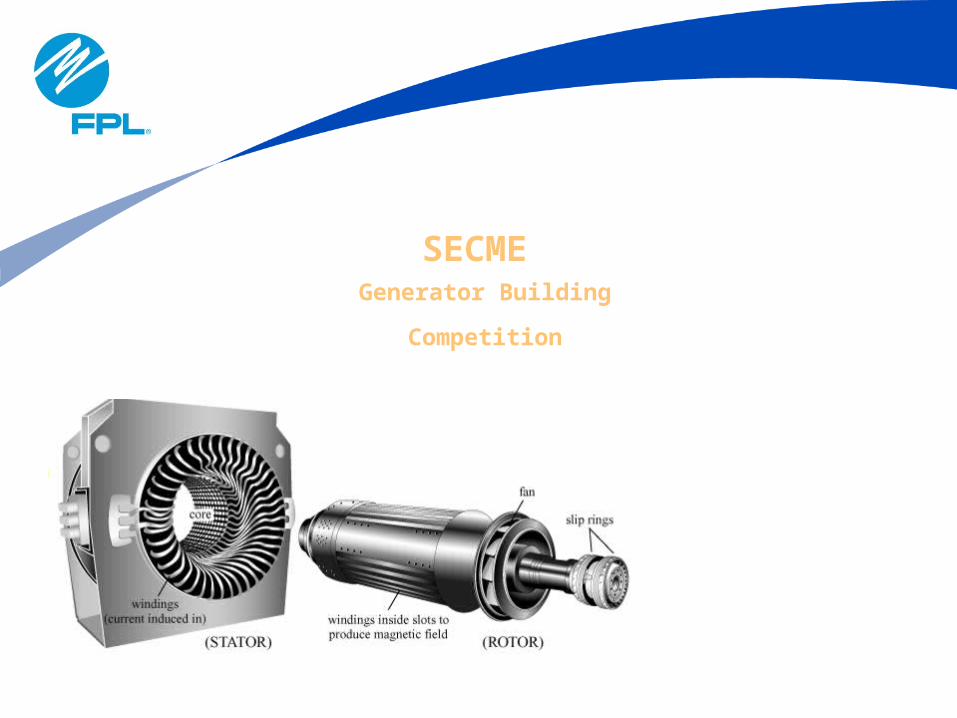
SECME Generator Building
Competition
2
• Purpose
• Basic Theory of Electrical Generators
• Competition
• Generator Building Instructions
TOPICS

3
PURPOSE
4
PurposeThe generator building competition will prepare students for other STEM programs by challenging them to understand the following:
• Basic forms of energy, including electrical and mechanical
• The basic magnetic theory
• The relationship between magnetic and electric fields.
• The flow of electrical circuits.
• The law of electromagnetic induction (Faraday’s Law).

6
BASIC THEORYof
ELECTRICALGENERATORS
7
Basic Theory
How does a Generator Work?• It’s a machine designed to convert Mechanical
Energy to Electrical Energy.• Based on the principle of electromagnetic
induction, which was introduced by Michael Faraday in 1831.
Three things are required to build a generator:• A magnetic field • Current carrying conductor• Relative motion between the two.
8
Basic TheoryMagnets
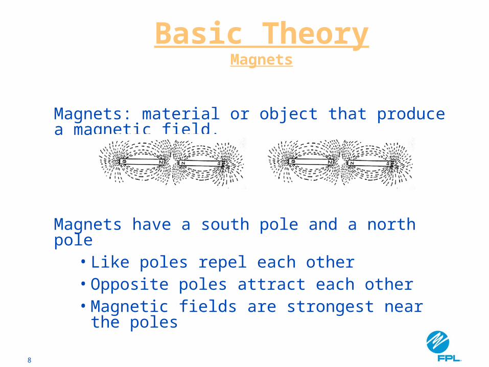
Magnets: material or object that produce a magnetic field.
Magnets have a south pole and a north pole• Like poles repel each other• Opposite poles attract each other• Magnetic fields are strongest near the poles
9
Basic TheoryMagnets
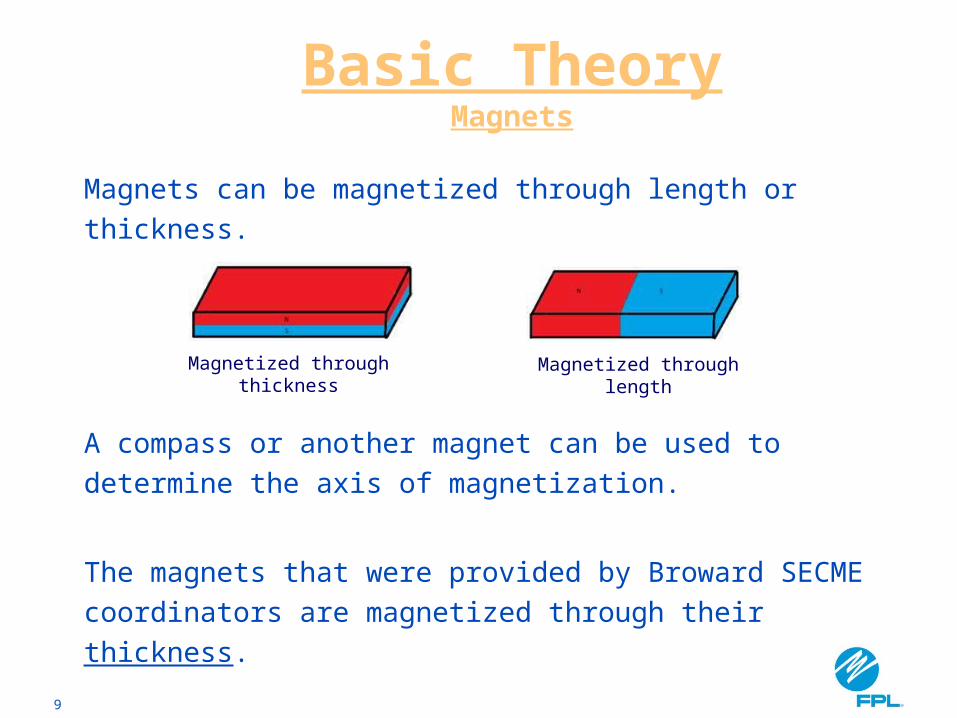
Magnets can be magnetized through length or thickness.
A compass or another magnet can be used to determine the axis of magnetization.
The magnets that were provided by Broward SECME coordinators are magnetized through their thickness.
Magnetized through thickness
Magnetized through length
10
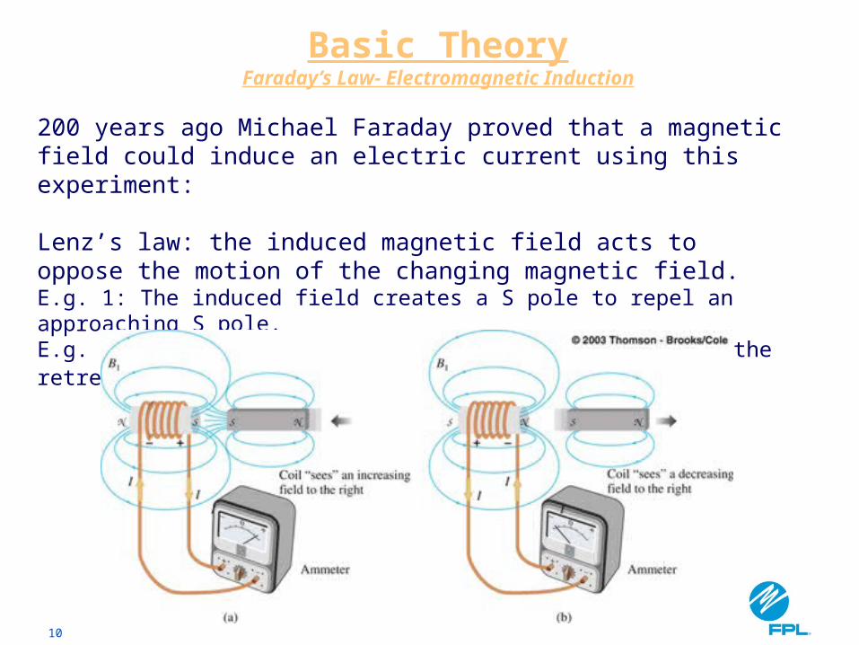
200 years ago Michael Faraday proved that a magnetic field could induce an electric current using this experiment:
Lenz’s law: the induced magnetic field acts to oppose the motion of the changing magnetic field.E.g. 1: The induced field creates a S pole to repel an approaching S pole.E.g. 2: The induced field creates a N pole to attract the retreating S pole.
Basic TheoryFaraday’s Law- Electromagnetic Induction
11
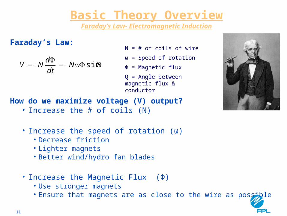
Basic Theory OverviewFaraday’s Law- Electromagnetic Induction
Faraday’s Law:
How do we maximize voltage (V) output?• Increase the # of coils (N)
• Increase the speed of rotation (ω)• Decrease friction• Lighter magnets• Better wind/hydro fan blades
• Increase the Magnetic Flux (Φ)• Use stronger magnets• Ensure that magnets are as close to the wire as possible
sinNdt
dNV
N = # of coils of wire
ω = Speed of rotation
Ф = Magnetic flux
Q = Angle between magnetic flux & conductor
12
COMPETITION
13
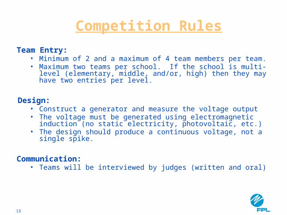
Competition Rules
Team Entry: • Minimum of 2 and a maximum of 4 team members per
team. • Maximum two teams per school. If the school is multi-level
(elementary, middle, and/or, high) then they may have two entries per level.
Design: • Construct a generator and measure the voltage output• The voltage must be generated using electromagnetic
induction (no static electricity, photovoltaic, etc.)• The design should produce a continuous voltage, not a
single spike.
Communication:• Teams will be interviewed by judges (written and oral)
14
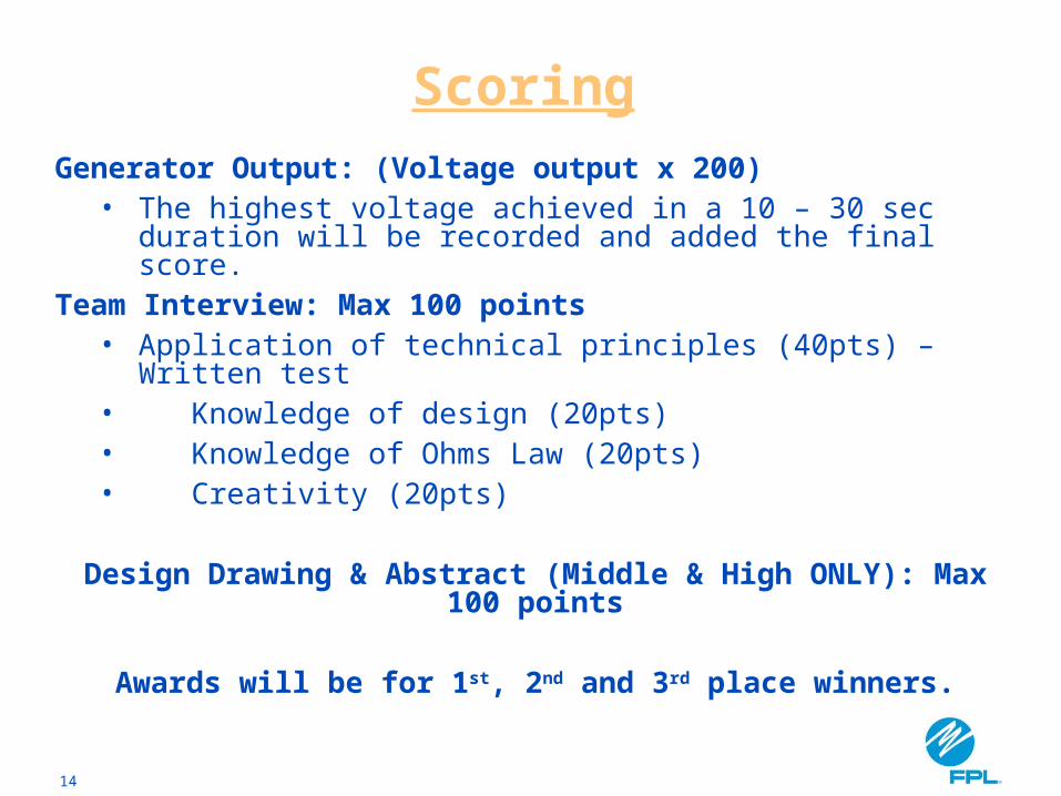
ScoringGenerator Output: (Voltage output x 200)
• The highest voltage achieved in a 10 – 30 sec duration will be recorded and added the final score.
Team Interview: Max 100 points• Application of technical principles (40pts) – Written test• Knowledge of design (20pts)• Knowledge of Ohms Law (20pts)• Creativity (20pts)
Design Drawing & Abstract (Middle & High ONLY): Max 100 points
Awards will be for 1st, 2nd and 3rd place winners.
15
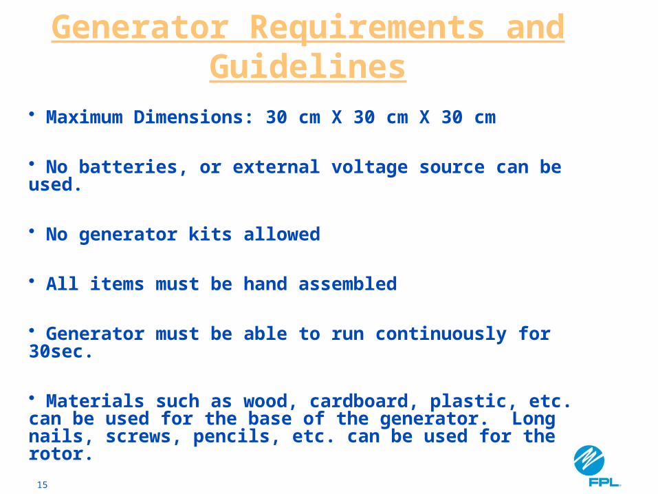
Generator Requirements and Guidelines
• Maximum Dimensions: 30 cm X 30 cm X 30 cm
• No batteries, or external voltage source can be used.
• No generator kits allowed
• All items must be hand assembled
• Generator must be able to run continuously for 30sec.
• Materials such as wood, cardboard, plastic, etc. can be used for the base of the generator. Long nails, screws, pencils, etc. can be used for the rotor.
16
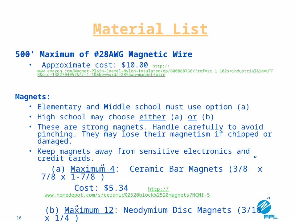
Material List
500' Maximum of #28AWG Magnetic Wire• Approximate cost: $10.00 http://
www.amazon.com/Magnet-Plain-Enamel-Nylon-Insulated/dp/B00B887G6Y/ref=sr_1_10?s=industrial&ie=UTF8&qid=1382704057&sr=1-10&keywords=28+awg+magnet+wire
Magnets:• Elementary and Middle school must use option (a)• High school may choose either (a) or (b)• These are strong magnets. Handle carefully to avoid pinching.
They may lose their magnetism if chipped or damaged.• Keep magnets away from sensitive electronics and credit cards.
(a) Maximum 4: Ceramic Bar Magnets (3/8” x 7/8 x 1-7/8”) Cost: $5.34 http://www.homedepot.com/s/ceramic%2520block%2520magnets?NCNI-5
(b) Maximum 12: Neodymium Disc Magnets (3/16” x 1/4”) Cost: $5.64 http://www.kjmagnetics.com/proddetail.asp?prod=D34-N52&cat=168
17
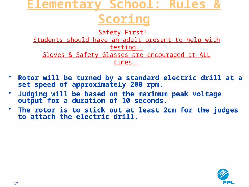
• Rotor will be turned by a standard electric drill at a set speed of approximately 200 rpm.
• Judging will be based on the maximum peak voltage output for a duration of 10 seconds.
• The rotor is to stick out at least 2cm for the judges to attach the electric drill.
Elementary School: Rules & Scoring
Safety First! Students should have an adult present to help with testing.
Gloves & Safety Glasses are encouraged at ALL times.
18
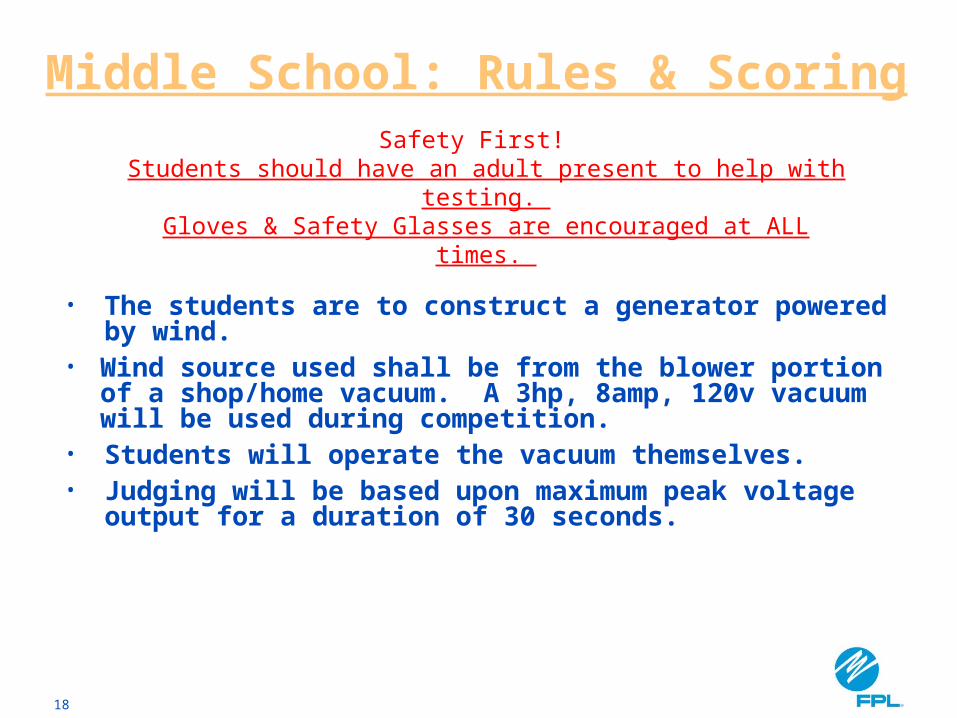
• The students are to construct a generator powered by wind.
• Wind source used shall be from the blower portion of a shop/home vacuum. A 3hp, 8amp, 120v vacuum will be used during competition.
• Students will operate the vacuum themselves.• Judging will be based upon maximum peak voltage
output for a duration of 30 seconds.
Middle School: Rules & ScoringSafety First!
Students should have an adult present to help with testing. Gloves & Safety Glasses are encouraged at ALL times.
19
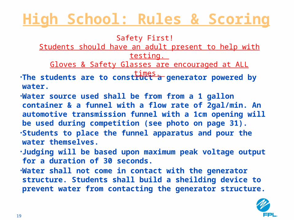
• The students are to construct a generator powered by water.
• Water source used shall be from from a 1 gallon container & a funnel with a flow rate of 2gal/min. An automotive transmission funnel with a 1cm opening will be used during competition (see photo on page 31).
• Students to place the funnel apparatus and pour the water themselves.
• Judging will be based upon maximum peak voltage output for a duration of 30 seconds.
• Water shall not come in contact with the generator structure. Students shall build a sheilding device to prevent water from contacting the generator structure.
High School: Rules & ScoringSafety First!
Students should have an adult present to help with testing. Gloves & Safety Glasses are encouraged at ALL times.
20
GENERATOR BUILDING
INSTRUCTIONS
21
Generator Composition
• The rotating parts of a generator are called the rotor. Can be a nail, screw, or metal rod.
• Basic generators use strong permanent magnets mounted on the rotor. Magnets always have a pair of poles (N & S).
• The stationary parts of a generator are called the stator. The stator consists of a tightly wound coil of wire.
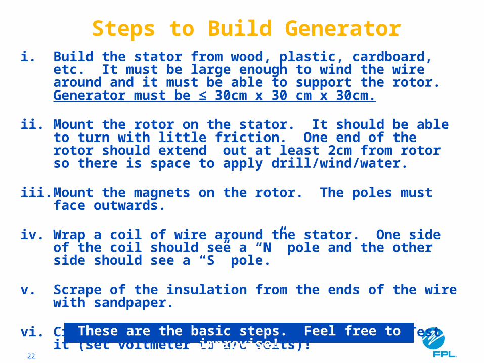
22
i. Build the stator from wood, plastic, cardboard, etc. It must be large enough to wind the wire around and it must be able to support the rotor. Generator must be ≤ 30cm x 30 cm x 30cm.
ii. Mount the rotor on the stator. It should be able to turn with little friction. One end of the rotor should extend out at least 2cm from rotor so there is space to apply drill/wind/water.
iii. Mount the magnets on the rotor. The poles must face outwards.
iv. Wrap a coil of wire around the stator. One side of the coil should see a “N” pole and the other side should see a “S” pole.
v. Scrape of the insulation from the ends of the wire with sandpaper.
vi. Create rotor blades to capture water/wind. Test it (set voltmeter to a/c volts)!
Steps to Build Generator
These are the basic steps. Feel free to improvise!
23
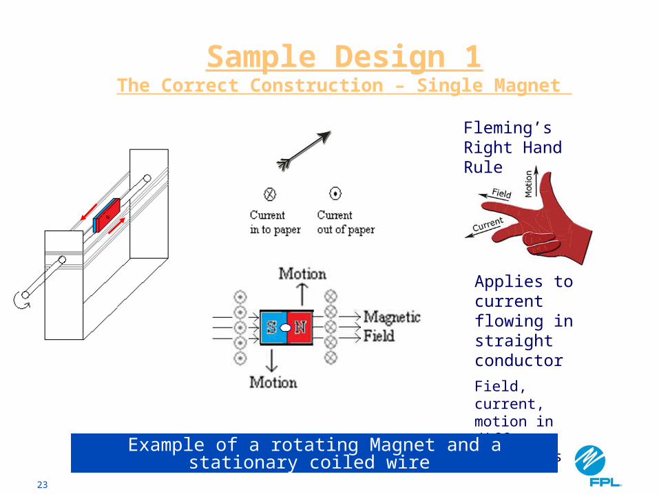
Sample Design 1The Correct Construction – Single Magnet
Direction of Current
Applies to current flowing in straight conductor
Field, current, motion in different dimensions
Fleming’s Right Hand Rule
Rotor
Example of a rotating Magnet and a stationary coiled wire
24
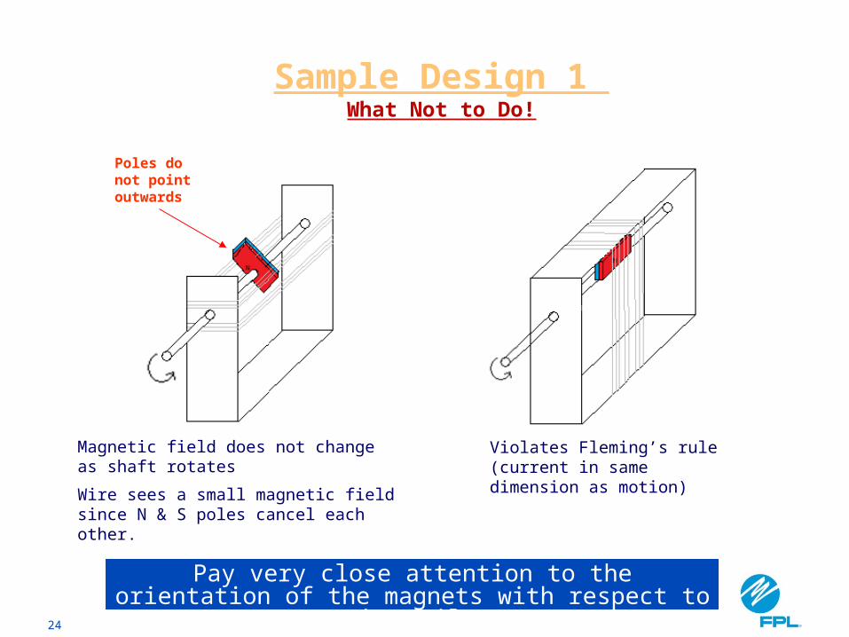
Sample Design 1 What Not to Do!
Magnetic field does not change as shaft rotates
Wire sees a small magnetic field since N & S poles cancel each other.
Violates Fleming’s rule (current in same dimension as motion)
Pay very close attention to the orientation of the magnets with respect to the coil.
Poles do not point outwards
25
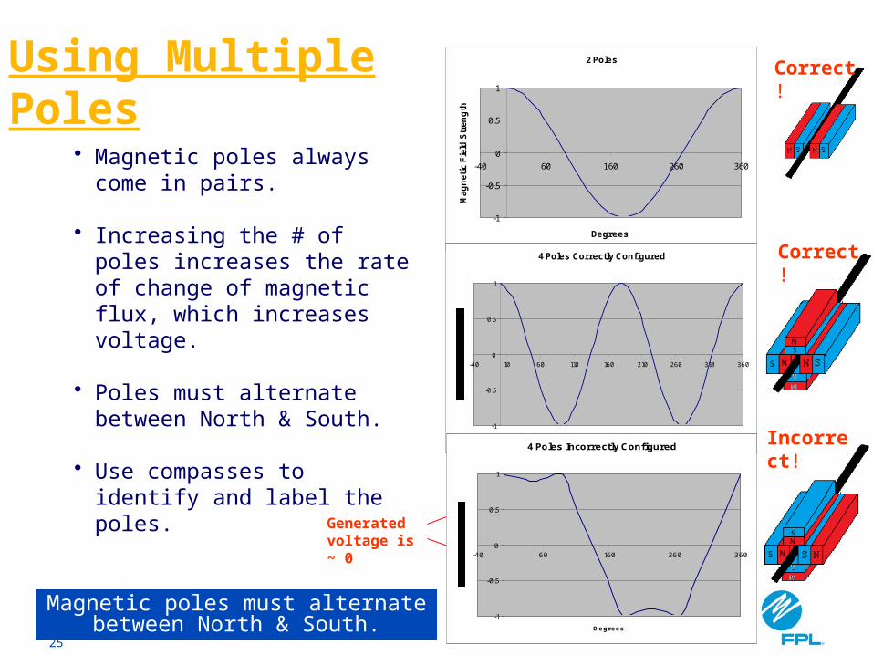
• Magnetic poles always come in pairs.
• Increasing the # of poles increases the rate of change of magnetic flux, which increases voltage.
• Poles must alternate between North & South.
• Use compasses to identify and label the poles.
2 Poles
-1
-0.5
0
0.5
1
-40 60 160 260 360
Degrees
Mag
neti
c F
ield
Str
eng
th
4 Poles Correctly Configured
-1
-0.5
0
0.5
1
-40 10 60 110 160 210 260 310 360
Degrees4 Poles Incorrectly Configured
-1
-0.5
0
0.5
1
-40 60 160 260 360
Degrees
Incorrect!
Magnetic poles must alternate between North & South.
Using Multiple Poles
Generated voltage is ~ 0
Correct!
Correct!
26
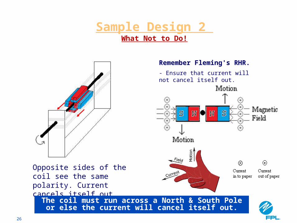
Sample Design 2 What Not to Do!
Opposite sides of the coil see the same polarity. Current cancels itself out
The coil must run across a North & South Pole or else the current will cancel itself out.
Remember Fleming's RHR.
- Ensure that current will not cancel itself out.
Direction of Current
27
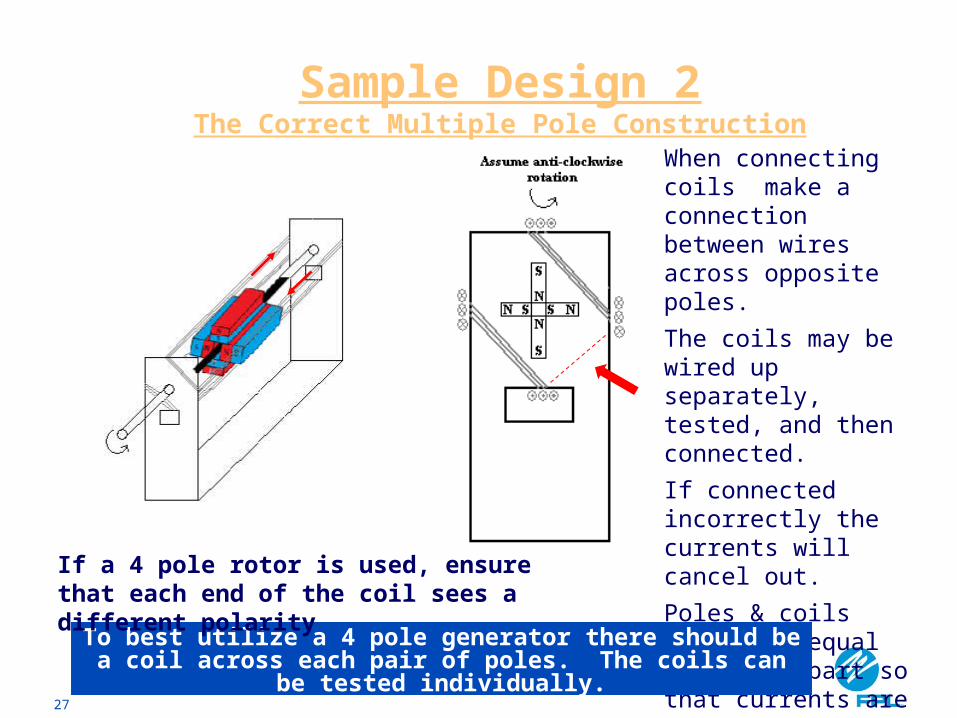
Sample Design 2The Correct Multiple Pole Construction
Stator
Direction of Current
When connecting coils make a connection between wires across opposite poles.
The coils may be wired up separately, tested, and then connected.
If connected incorrectly the currents will cancel out.
Poles & coils should be equal distance apart so that currents are in phase.
To best utilize a 4 pole generator there should be a coil across each pair of poles. The coils can be tested individually.
If a 4 pole rotor is used, ensure that each end of the coil sees a different polarity
28
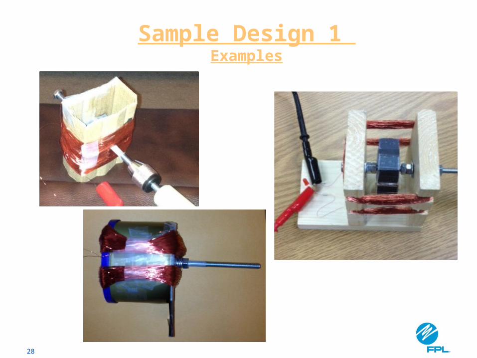
Sample Design 1 Examples
29
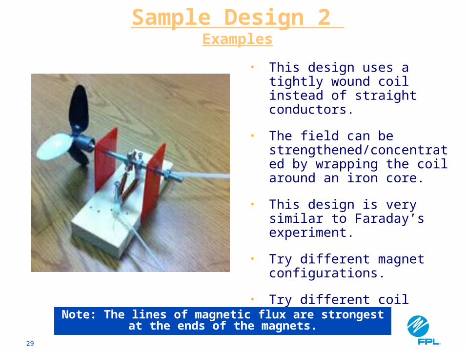
• This design uses a tightly wound coil instead of straight conductors.
• The field can be strengthened/concentrated by wrapping the coil around an iron core.
• This design is very similar to Faraday’s experiment.
• Try different magnet configurations.
• Try different coil shapes.
Sample Design 2 Examples
Note: The lines of magnetic flux are strongest at the ends of the magnets.
30
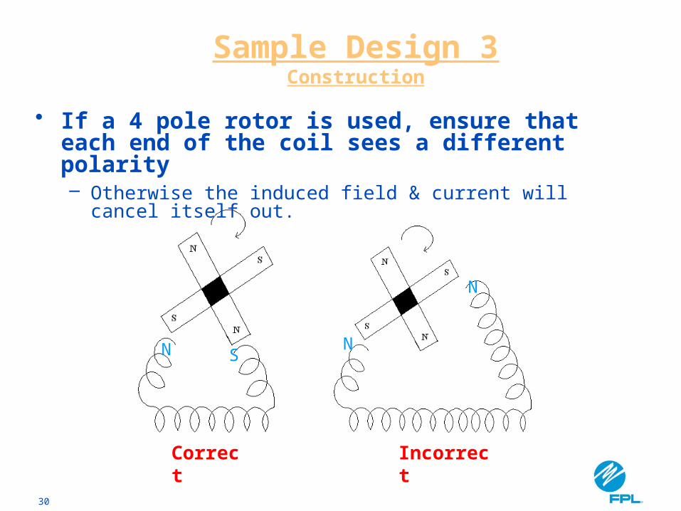
• If a 4 pole rotor is used, ensure that each end of the coil sees a different polarity– Otherwise the induced field & current will cancel itself
out.
N N
N
S
Correct Incorrect
Sample Design 3Construction
31
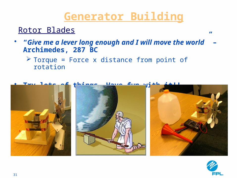
• “Give me a lever long enough and I will move the world” – Archimedes, 287 BC Torque = Force x distance from point of rotation
• Try lots of things. Have fun with it!!
Rotor Blades
Generator Building

32
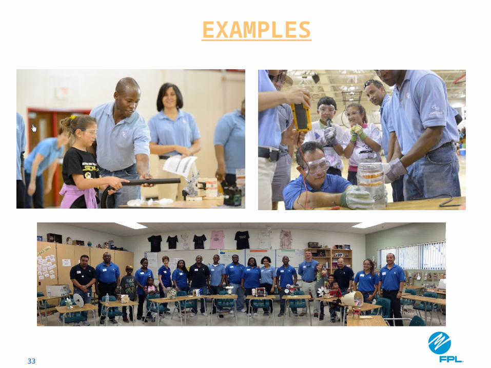
EXAMPLES
33
EXAMPLES
34
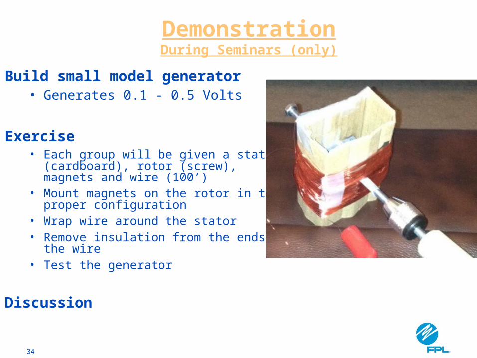
Build small model generator• Generates 0.1 - 0.5 Volts
Exercise• Each group will be given a stator
(cardboard), rotor (screw), magnets and wire (100’)
• Mount magnets on the rotor in the proper configuration
• Wrap wire around the stator• Remove insulation from the ends of the
wire• Test the generator
Discussion
DemonstrationDuring Seminars (only)