Embed Size (px)
Citation preview
Indoor Air Quality
2 0 1 8S E C O N D E D I T I O N
HandbookNON-MANDATORY DOCUMENT
INDOOR AIR QUALITY
HANDBOOK
2018
Handbook: Indoor Air Quality
Australian Building Codes Board Page ii
Copyright and licence notice
© 2018 Commonwealth of Australia and States and Territories of Australia Ownership of intellectual property rights
Unless otherwise noted, copyright (and any other intellectual property rights, if any) in this publication is jointly owned by the Commonwealth, States and Territories of Australia.
Creative Commons licence Attribution CC BY-NC-ND 4.0
All material in this publication is licensed under a Creative Commons Attribution-NonCommercial-NoDerivatives 4.0 International Licence, save for logos. Attribution-
NonCommercial-NoDerivatives 4.0 International Licence is a standard form licence agreement that does not permit any commercial use or derivatives of the original work. Under this licence: you may only distribute a verbatim copy of the work and must not adapt or change the work in any way. You must give appropriate credit and provide a link to the licence. You may do so in
any reasonable manner, but not in any way that suggests the Commonwealth of Australia, States and Territories of Australia or Australian Building Codes Board endorses you or your use. You may not use the material for commercial purposes. If you remix, transform, or build
upon the material for your own use, you may not distribute the modified material.
The full licence terms are available from http://creativecommons.org/licenses/by-nc-nd/4.0/legalcode.
Content contained herein should be attributed as:
The Indoor Air Quality Handbook© as released by the Australian Building Codes Board on behalf of the Commonwealth of Australia and States and Territories of Australia
Disclaimer
This Handbook is intended to be used as guidance material only, and is in no way a substitute for the NCC and related State and Territory legislation.
The Chief Executive Officer of the Australian Building Codes Board Office, as agent for the Commonwealth of Australia and States and Territories of Australia, does not accept any liability howsoever arising from or connected to the use or reliance on any information in this publication to the maximum extent permitted by law.
The information in this publication is provided on the basis that all persons accessing the information undertake responsibility for assessing the relevance and accuracy of the information to their particular circumstances.
Published by: Australian Building Codes Board First published: October 2016 GPO Box 2013 CANBERRA ACT 2601 Print version: 2.0 Phone: 1300 134 631 Release date: March 2018 Email: [email protected] www.abcb.gov.au
Handbook: Indoor Air Quality
Australian Building Codes Board Page iii
Preface
The Inter-Government Agreement (IGA) that governs the ABCB places a strong
emphasis on reducing reliance on regulation, including consideration of non-regulatory
alternatives such as non-mandatory guidelines, handbooks and protocols.
This Handbook is one of a series produced by the ABCB. The series of Handbooks is
being developed in response to comments and concerns expressed by government,
industry and the community that relate to the built environment. The topics of
Handbooks expand on areas of existing regulation or relate to topics which have, for a
variety of reasons, been deemed inappropriate for regulation. The aim of the
Handbooks is to provide construction industry participants with non-mandatory advice
and guidance on specific topics.
The application of the Indoor Air Quality (IAQ) Verification Methods has been identified
as an issue that requires consistent uniform guidance.
The Indoor Air Quality Handbook has been developed to foster a greater understanding
of the IAQ Verification Methods that are contained within the National Construction
Code (NCC) Volumes One and Two, i.e. Verification Methods FV4.1 and FV4.2 of NCC
2016 Volume One and Verification Method V2.4.5 of NCC 2016 Volume Two.
This Handbook addresses the issues covered in generic terms, and is not a document
that sets out a specific process of using the IAQ Verification Methods. It is expected that
this Handbook will be used to develop solutions relevant to specific situations in
accordance with the generic principles and criteria contained herein.
In 2018, this Handbook was updated to reflect the changes made as part of NCC 2016
Volume One Amendment 1.
Handbook: Indoor Air Quality
Australian Building Codes Board Page iv
Acknowledgements
This Handbook was developed by Mr Vince Aherne for the ABCB, with support from the
Australian Institute of Refrigeration, Airconditioning and Heating (AIRAH). The
Handbook is issued by the ABCB and AIRAH to assist in disseminating information to
building and construction practitioners and to foster a greater understanding of the
Ventilation (Indoor Air Quality) Verification Methods that are contained within the
Volumes One and Two of the NCC.
Handbook: Indoor Air Quality
Australian Building Codes Board Page v
Style
To assist in explaining the NCC IAQ Verification Methods, various coloured boxes are
used throughout the Handbook to highlight examples, important information and
extracts from the NCC. The following describes these in more detail:
Example:
Examples are highlighted in orange boxes and are generally used to explain the
application of a particular NCC requirement.
Reminder/Alert:
Reminders and alerts are highlighted in pink boxes and are used to remind or alert the
reader to important information that should be considered in conjunction with the
information under discussion.
NCC extract:
Blue highlighted boxes indicate that this text is an extract of the NCC which was current
at the time this Handbook was published.
Handbook: Indoor Air Quality
Australian Building Codes Board Page vi
Contents
1 Introduction ........................................................................................................... 1
1.1 Purpose ...................................................................................................... 1
2 Background ........................................................................................................... 2
2.1 Scope ......................................................................................................... 2
2.2 Limitations .................................................................................................. 2
2.3 Other Handbooks by the ABCB .................................................................. 3
2.4 Definition of Terms ..................................................................................... 3
2.4.1 NCC Defined Terms ....................................................................... 3
2.4.2 Acronyms ....................................................................................... 6
2.5 Introduction to the Performance-based NCC .............................................. 7
2.5.1 The Australian Building Codes Board ............................................ 7
2.5.2 The NCC and the BCA ................................................................... 7
2.5.3 Legislation governing building, plumbing and drainage work ......... 8
2.5.4 The NCC Compliance Structure..................................................... 8
2.5.5 The Performance Requirements .................................................... 9
2.5.6 Assessment Methods ................................................................... 11
2.6 NCC Ventilation Performance Requirements ........................................... 16
2.6.1 NCC Volume One Ventilation Performance Requirements .......... 17
2.6.2 NCC Volume Two Ventilation Performance Requirements .......... 17
2.7 Understanding Performance Solutions ..................................................... 18
2.7.1 Quantifying Performance ............................................................. 18
2.7.2 Benefits of the Performance Approach ........................................ 19
2.7.3 Typical Performance Solution Compliance Steps ........................ 19
2.7.4 Role of Verification Methods ........................................................ 20
2.7.5 Benefits of Verification Methods................................................... 20
3 Building Ventilation............................................................................................. 22
3.1 Building Ventilation Systems .................................................................... 22
3.1.1 Ventilation .................................................................................... 22
3.1.2 Natural Ventilation........................................................................ 22
3.1.3 Mechanical Ventilation ................................................................. 23
Handbook: Indoor Air Quality
Australian Building Codes Board Page vii
3.1.4 Hybrid and Mixed-mode Ventilation ............................................. 23
3.2 Indoor Air and Indoor Air Contamination .................................................. 23
3.2.1 Indoor Air Contaminant Background ............................................ 23
3.2.2 Effects of Exposure ...................................................................... 27
3.2.3 Quantifying Indoor Air Contamination .......................................... 27
3.2.4 Sources of Indoor Air Contaminants ............................................ 28
3.2.5 Indoor Air Quality (IAQ) ................................................................ 29
3.2.6 Indoor Environment Quality (IEQ) ................................................ 30
3.3 Outdoor Air and Outdoor Air Contamination ............................................. 30
3.3.1 Outdoor Air Contaminants Background ....................................... 30
3.3.2 National Standards for Outdoor Air Pollutants in Australia ........... 31
3.3.3 Documenting Australia's Air Quality ............................................. 31
3.3.4 National Air Quality Standards ..................................................... 31
3.3.5 Monitoring and Reporting ............................................................. 32
3.3.6 Sources of Outdoor Air Contaminants ......................................... 33
4 Indoor Air Contaminant Control ........................................................................ 34
4.1 Air Contaminants to be Verified ................................................................ 34
4.1.1 Carbon Dioxide, CO2 ................................................................... 34
4.1.2 Carbon Monoxide, CO ................................................................. 36
4.1.3 Nitrogen Dioxide, NO2 .................................................................. 38
4.1.4 Ozone, O3 .................................................................................... 39
4.1.5 Total Volatile Organic Compounds, TVOC .................................. 40
4.1.6 Formaldehyde, CH2O ................................................................... 42
4.1.7 Particulate Matter, PM ................................................................. 44
4.2 Controlling Air Contaminants .................................................................... 46
4.2.1 Avoidable and Unavoidable Contaminants .................................. 46
4.2.2 Hierarchy of Contaminant Controls .............................................. 46
4.2.3 Air Contaminant Balance ............................................................. 47
4.3 Indoor Air Contaminant Control Strategies ............................................... 47
4.3.1 Limit Contaminant Emitting Materials ........................................... 48
4.3.2 Limit Indoor Combustion Devices ................................................ 48
4.3.3 Seal Building to Control Infiltration and Exfiltration ...................... 49
4.3.4 Ventilate with Local or General Exhaust ...................................... 50
Handbook: Indoor Air Quality
Australian Building Codes Board Page viii
4.3.5 Air Distribution Design ................................................................. 50
4.3.6 Ventilation effectiveness .............................................................. 50
4.3.7 Air Cleaning and Contaminant Removal ...................................... 51
4.3.8 Ventilate with Clean Outdoor Air .................................................. 56
4.3.9 Construction, Commissioning, Training and Labelling ................. 56
4.3.10 Operational Planning ................................................................... 58
4.4 Design Strategies for Controlling Air Quality............................................. 60
4.4.1 Integrated Design Targeting IAQ ................................................. 61
4.4.2 Ventilation Effectiveness Targeting Air Contaminants ................. 62
4.4.3 System Documentation ................................................................ 62
4.4.4 System Maintainability ................................................................. 63
4.4.5 Location of Air Intakes and Discharges ........................................ 63
4.4.6 Addressing Entry Ways ................................................................ 64
5 Ventilation Requirements ................................................................................... 65
5.1 Current NCC Compliance Pathways ........................................................ 65
5.1.1 NCC Ventilation Requirements .................................................... 65
5.1.2 NCC Volume One Class 2 to 9 Building Ventilation (excluding
Class 7a carparks) .................................................................................... 65
5.1.3 NCC Volume One Class 7a Carpark Ventilation .......................... 66
5.1.4 NCC Volume Two Class 1 Building Ventilation ............................ 66
5.2 IAQ Verification Method Contaminant Limits ............................................ 67
5.3 Understanding the IAQ Verification Methods ............................................ 67
5.3.1 Verification Methods FV4.1 and V2.4.5 ........................................ 68
5.3.2 Verification Method FV4.2 ............................................................ 69
5.3.3 Exclusions from the IAQ Verification Methods ............................. 69
6 Applying the IAQ Verification Methods ............................................................. 72
6.1 Benefits of Performance-based Ventilation Solutions ............................... 72
6.2 The Risks of Performance-based Ventilation Solutions ............................ 72
6.3 Developing a Performance-based Ventilation Solution ............................. 73
6.1.1 Performance Drivers .................................................................... 73
6.1.2 Design Objectives ........................................................................ 73
6.1.3 Design Criteria ............................................................................. 73
6.4 Design Inputs for Performance-based Ventilation Systems ...................... 74
Handbook: Indoor Air Quality
Australian Building Codes Board Page ix
6.1.4 Design Inputs for Occupied Space Ventilation Systems .............. 74
6.1.5 Design Inputs for Carpark Ventilation Systems ............................ 75
6.5 Verifying a building solution against the Verification Method .................... 77
6.6 Modelling IAQ and Air Contaminant Transport ......................................... 77
6.1.6 Principles of Simulation ................................................................ 78
6.1.7 Air Contaminant Modelling ........................................................... 79
6.1.8 Microscopic Modelling Techniques .............................................. 80
6.6.1 Macroscopic Modelling Techniques ............................................. 81
6.6.2 Boundaries in a Model ................................................................. 84
6.6.3 Contaminant Sources and Sinks .................................................. 84
6.6.4 Building Classifications ................................................................ 85
6.6.5 Ventilation and Infiltration ............................................................. 86
6.6.6 Local and General Exhaust .......................................................... 86
6.6.7 Air Cleaning Devices .................................................................... 86
6.6.8 Complexities of Simulation ........................................................... 86
6.7 IAQ Modelling Software Tools and Platforms ........................................... 88
6.7.1 Modelling Software ...................................................................... 88
6.7.2 Interpretation and Graphical Visualisation of Results................... 88
6.7.3 Validating IAQ Models ................................................................. 89
6.8 Monitoring Air Contaminant Levels ........................................................... 89
6.8.1 Monitoring .................................................................................... 89
6.8.2 Personal Monitors ........................................................................ 89
6.8.3 Remote Monitors.......................................................................... 90
6.8.4 Monitoring Ventilation Rates ........................................................ 90
6.8.5 NABERS IE Sampling and Measurement Protocols .................... 90
6.9 Testing Air Contaminant Concentration Levels......................................... 91
6.9.1 Measurement options .................................................................. 91
6.9.2 Sampling Options......................................................................... 91
6.9.3 Measuring Contaminant Levels.................................................... 92
References, Further Reading and Information Sources ......... 93
A.1 References ............................................................................................... 93
A.2 Further reading ......................................................................................... 95
A.2.1 Papers ......................................................................................... 95
Handbook: Indoor Air Quality
Australian Building Codes Board Page x
A.2.2 Brochures and guides .................................................................. 96
A.3 Additional Information Sources ................................................................. 97
Data Sources for low-emission materials ................................ 98
B.1 Introduction ............................................................................................... 98
B.2 Evaluating and Selecting Low-emission Products .................................... 98
B.2.1 Emissions from Materials ............................................................. 99
B.2.2 Safety Data Sheet (SDS) ............................................................. 99
B.2.3 Third-Party Certification ............................................................. 100
B.2.4 Green Product Standards .......................................................... 100
B.2.5 Green Product Directories ......................................................... 100
B.3 Online Resources ................................................................................... 100
B.4 Making Material Selections ..................................................................... 103
B.5 Specification Guidelines ......................................................................... 103
B.6 Test methods for quantifying air contaminant emissions ........................ 103
B.6.1 Test Methods for Office Equipment ............................................ 103
B.6.2 Test Methods for Materials Emissions ....................................... 104
B.6.3 Test Methods for Outdoor Air Contaminants .............................. 106
IAQ Models and Simulation Software .................................... 107
C.1 Simulation software for air contaminant concentrations ......................... 107
C.1.1 CONTAM ................................................................................... 107
C.1.2 CONTAM Model/TRNSYS Simulation ....................................... 108
C.1.3 CHAMPS-Multizone ................................................................... 108
C.1.4 IA-QUEST .................................................................................. 109
C.1.5 I-BEAM ...................................................................................... 109
C.1.6 IAQ Estimator............................................................................. 110
C.1.7 IAQ Tools ................................................................................... 110
C.1.8 TRNFlow .................................................................................... 110
C.1.9 DesignBuilder............................................................................. 111
C.1.10 BIM Platforms and IAQ .............................................................. 111
C.2 CFD software for air contaminant concentrations ................................... 111
C.2.1 Class 7a Carpark Ventilation ..................................................... 111
C.2.2 ANSYS Fluid Dynamics® ........................................................... 111
Handbook: Indoor Air Quality
Australian Building Codes Board Page xi
C.2.3 FloVENT® .................................................................................. 112
C.2.4 OpenFOAM® ............................................................................. 112
C.2.5 PHOENICS® ............................................................................. 112
C.2.6 simFlow® ................................................................................... 112
C.2.7 STAR-CCM+® ........................................................................... 113
C.2.8 HyperWorks® ............................................................................ 113
C.3 Vehicle emission models for Class 7a Carpark Ventilation ..................... 113
C.3.1 ARTEMIS ................................................................................... 113
C.3.2 CUEDC ...................................................................................... 113
C.3.3 COPERT 4 ................................................................................. 114
C.3.4 HBEFA ....................................................................................... 114
C.3.5 MOVES ...................................................................................... 114
C.3.6 PHEM ........................................................................................ 114
C.3.7 VERSIT+ .................................................................................... 115
C.4 Inputs and Assumptions ......................................................................... 115
C.5 Sensitivity Analysis ................................................................................. 116
C.6 Procuring simulation services ................................................................. 116
C.7 Competencies of the Simulator............................................................... 116
NCC Building Classifications.................................................. 117
Handbook: Indoor Air Quality
Australian Building Codes Board Page 1
1 Introduction
Reminder:
This Handbook is not mandatory or regulatory in nature and compliance with it will not
necessarily discharge a user's legal obligations. The Handbook should only be read and
used subject to, and in conjunction with, the general disclaimer at page i.
The Handbook also needs to be read in conjunction with the relevant legislation of the
appropriate State or Territory. It is written in generic terms and it is not intended that the
content of the Handbook counteract or conflict with the legislative requirements, any
references in legal documents, any handbooks issued by the Administration or any
directives by the Appropriate Authority.
1.1 Purpose
This Handbook was developed to provide support in understanding Indoor Air Quality
(IAQ) Verification Methods FV4.1 and FV4.2 of NCC Volume One and V2.4.5 of NCC
Volume Two. These IAQ Verification Methods quantify ventilation system performance
through the specification of maximum air contaminant limits (for a range of indoor air
contaminants) that must be achieved for the quality of the indoor air to be deemed
“adequate”. The IAQ Verification Methods help define the point at which adequate air
quality has been achieved, which allows the performance of a proposed ventilation
building solution to be verified.
The purpose of this Handbook is to:
describe the principles behind the development of the IAQ Verification Methods;
provide examples of how they can be applied in practice; and
provide information and data sources to support the use of the IAQ Verification
Methods.
Appendix A provides a list of the documents referred to in this Handbook as well as
additional information sources on the topic.

Handbook: Indoor Air Quality
Australian Building Codes Board Page 2
2 Background
2.1 Scope
This Handbook covers IAQ Verification Methods FV4.1 Verification of suitable indoor air
quality and FV4.2 Verification of suitable indoor air quality for carparks from NCC
Volume One and IAQ Verification Method V2.4.5 Verification of suitable indoor air
quality from NCC Volume Two.
The Handbook provides some background on the application of Verification Methods
within the NCC compliance framework as well as on the general principles of building
ventilation, air contaminants, indoor air quality and a range of air contaminant controls.
It provides a detailed analysis of the ventilation Performance Requirements of the NCC
and how the IAQ Verification Methods could be used to demonstrate compliance with
those requirements. The Handbook also provides some broad guidance on design
strategies, modelling principles, and sampling and testing protocols that could assist
practitioners develop and validate Performance Solutions for maintaining adequate air
quality in buildings with outdoor air ventilation.
2.2 Limitations
This Handbook is not intended to:
override or replace any legal rights, responsibilities or requirements; or
provide users with the specifics of the NCC.
This Handbook is intended to make users aware of provisions that may affect them, not
exactly what is required by those provisions. If users determine that a provision may
apply to them, the NCC should be read to determine the specifics of the provision.
This Handbook has been written to complement NCC 2016 Volume One Amendment 1,
its application to later editions of the NCC needs to be confirmed by the user.
This Handbook does not deal with the health aspects of tobacco smoke or e-cigarette
exposure. This reflects the provisions in the NCC Deemed-to-Satisfy Provisions and
Australian Standard AS 1668.2-2012 which are based on the ventilation of enclosures in
which smoking does not occur.
While biological contaminants such as moulds and fungi are known air contaminants
that can degrade indoor air quality, the methodology for the accurate modelling,
sampling, testing and measurement of many biological species is not universally
agreed. Biological contaminants including house dust mites, moulds and fungi,
Handbook: Indoor Air Quality
Australian Building Codes Board Page 3
allergens, bacterial and viral pollutants, are not covered by the IAQ Verification
Methods. For further information regarding moulds and fungi that may result because of
condensation problems and inadequate ventilation, refer to the ABCB Condensation in
Buildings Handbook available from the ABCB website1.
2.3 Other Handbooks by the ABCB
The ABCB has produced a range of Handbooks and other educational material relating
to topics associated with the NCC. They can be downloaded from the ABCB website:
www.abcb.gov.au.
2.4 Definition of Terms
2.4.1 NCC Defined Terms
As both a legally enforceable and technical document, the NCC uses specific language
and terms. Words with special meanings are defined or have explanatory information
accompanying them. The NCC contains definitions for the following terms which may be
relevant to IAQ verification and of use when detailing Performance Solutions for building
ventilation:
Appropriate authority means the relevant authority with the statutory responsibility to
determine the particular matter.
Accredited Testing Laboratory means—
(a) an organisation accredited by the National Association of Testing Authorities
(NATA) to undertake the relevant tests; or
(b) an organisation outside Australia accredited to undertake the relevant tests by an
authority, recognised by NATA through a mutual recognition agreement; or
(c) an organisation recognised as being an Accredited Testing Laboratory under
legislation at the time the test was undertaken.
Assessment Method means a method that can be used for determining that a
Performance Solution or Deemed-to-Satisfy Solution complies with the Performance
Requirements.
Appropriately qualified person means a person recognised by the appropriate
authority as having qualifications and/or experience in the relevant discipline in
question.
1 www.abcb.gov.au
Handbook: Indoor Air Quality
Australian Building Codes Board Page 4
Carpark means a building that is used for the parking of motor vehicles but is neither a
private garage nor used for the servicing of vehicles, other than washing, cleaning or
polishing.
Certificate of Accreditation means a certificate issued by a State or Territory
accreditation authority stating that the properties and performance of a building material
or method of construction or design fulfil specific requirements of the BCA.
Certificate of Conformity means a certificate issued under the ABCB scheme for
products and systems certification stating that the properties and performance of a
building material or method of construction or design fulfil specific requirements of the
BCA.
Certification body means a person or organisation operating in the field of material,
product, form of construction or design certification that has been accredited by the
Joint Accreditation System of Australia and New Zealand (JAS-ANZ) for a purpose
other than as part of the CodeMark or CodeMark Australia Certification Scheme.
Deemed-to-Satisfy Provisions means provisions which are deemed to satisfy the
Performance Requirements.
Deemed-to-Satisfy Solution means a method of satisfying the Deemed-to-Satisfy
Provisions.
Equivalent means equivalent to the level of health, safety and amenity provided by the
Deemed-to-Satisfy Provisions.
Expert Judgement means the judgement of an expert who has the qualifications and
experience to determine whether a Performance Solution or Deemed-to-Satisfy Solution
complies with the Performance Requirements.
Habitable room means a room used for normal domestic activities, and—
(a) includes a bedroom, living room, lounge room, music room, television room,
kitchen, dining room, sewing room, study, playroom, family room, home theatre
and sunroom; but
(b) excludes a bathroom, laundry, water closet, pantry, walk-in wardrobe, corridor,
hallway, lobby, photographic darkroom, clothes-drying room, and other spaces of
a specialised nature occupied neither frequently nor for extended periods.
Open-deck carpark means a carpark in which all parts of the parking storeys are
cross-ventilated by permanent unobstructed openings in not fewer than 2 opposite or
approximately opposite sides, and—
(a) each side that provides ventilation is not less than 1/6 of the area of any other side;
and
Handbook: Indoor Air Quality
Australian Building Codes Board Page 5
(b) the openings are not less than ½ of the wall area of the side concerned.
Outdoor air means air outside the building.
Performance Requirement means a requirement which states the level of
performance which a Performance Solution or Deemed-to-Satisfy Solution must meet.
Performance Solution (Alternative Solution) means a method of complying with the
Performance Requirements other than by a Deemed-to-Satisfy Solution.
Private garage means—
(a) any garage associated with a Class 1 building; or
(b) any single storey of a building of another Class containing not more than 3 vehicle
spaces, if there is only one such storey in the building; or
(c) any separate single storey garage associated with another building where such
garage contains not more than 3 vehicle spaces.
Professional engineer means a person who is—
(a) if legislation is applicable — a registered professional engineer in the relevant
discipline who has appropriate experience and competence in the relevant field; or
(b) if legislation is not applicable—
(i) a Corporate Member of the Institution of Engineers, Australia; or
(ii) eligible to become a Corporate Member of the Institution of Engineers,
Australia, and has appropriate experience and competence in the relevant
field.
Required means required to satisfy a Performance Requirement or a Deemed-to-
Satisfy Provision of the BCA as appropriate.
Ventilation opening means an opening in the external wall, floor or roof of a building
designed to allow air movement into or out of the building by natural means including a
permanent opening, an openable part of a window, a door or other device which can be
held open.
Verification Method means a test, inspection, calculation or other method that
determines whether a Performance Solution complies with the relevant Performance
Requirements.
Window includes a roof light, glass panel, glass block or brick, glass louvre, glazed
sash, glazed door, or other device which transmits natural light directly from outside a
building to the room concerned when in the closed position.
Handbook: Indoor Air Quality
Australian Building Codes Board Page 6
2.4.2 Acronyms
The following Acronyms are used in the body of this Handbook:
ABCB Australian Building Codes Board
BCA Building Code of Australia
CFD Computational Fluid Dynamics
GUI Graphical User Interface
HVAC Heating, Ventilation and Air-Conditioning
IAQ Indoor Air Quality
IEQ Indoor Environment Quality
IGA Inter-government Agreement
NCC National Construction Code 2016
NATA National Association of Testing Authorities
NEPM National Environment Protection Measure (Ambient Air Quality)
OH&S Occupational Health and Safety
PCA Plumbing Code of Australia
PCO Photocatalytic Oxidation
PM Particulate Matter
SDS Safety Data Sheet
SGS Sub-grid scale
PPM Parts Per Million
TVOC Total Volatile Organic Compounds
VOC Volatile Organic Compound
WHO World Health Organisation

Handbook: Indoor Air Quality
Australian Building Codes Board Page 7
WHS Work Health Safety
2.5 Introduction to the Performance-based NCC
2.5.1 The Australian Building Codes Board
The Australian Building Codes Board (ABCB) is a joint initiative of all three levels of
government in Australia and includes representatives from the building and plumbing
industries. The Board was established by an Inter-government Agreement (IGA) signed
by the Commonwealth, States and Territories on 1 March 1994.
The Board’s mission is to address issues relating to safety, health, amenity and
sustainability in the design and performance of buildings through the NCC and the
development of effective regulatory systems and appropriate non-regulatory solutions.
For further information about the Board and the ABCB office, visit the ABCB website at
www.abcb.gov.au.
2.5.2 The NCC and the BCA
The ABCB is, amongst other roles, a code writing body for the States and Territories.
The series of construction codes is collectively named the NCC. The NCC is a uniform
set of technical provisions for building work and plumbing and drainage installations
throughout Australia whilst allowing for variations in climate and geological conditions.
The NCC comprises the Building Code of Australia (BCA) Volumes One and Two; and
the Plumbing Code of Australia (PCA), as Volume Three.
NCC Volume One pertains primarily to Class 2 to Class 9 buildings while NCC Volume
Two pertains primarily to Class 1 and 10 buildings. NCC Volume Three pertains
primarily to plumbing and drainage associated with all classes of buildings. See
Appendix D for an explanation of the NCC building classifications.
All three volumes are drafted in a performance-based format allowing flexibility to
develop Performance Solutions based on existing or new innovative building, plumbing
and drainage products, systems and designs, or the use of the Deemed-to-Satisfy
(DTS) Provisions to develop a DTS Solution. A combination of Performance Solutions
and DTS Solutions can also be developed.
To assist in interpreting the requirements of NCC Volume One, the ABCB also
publishes a non-mandatory Guide to Volume One. For NCC Volumes Two and Three,
clearly identified non-mandatory explanatory information boxes are included in the text
to assist users.
Handbook: Indoor Air Quality
Australian Building Codes Board Page 8
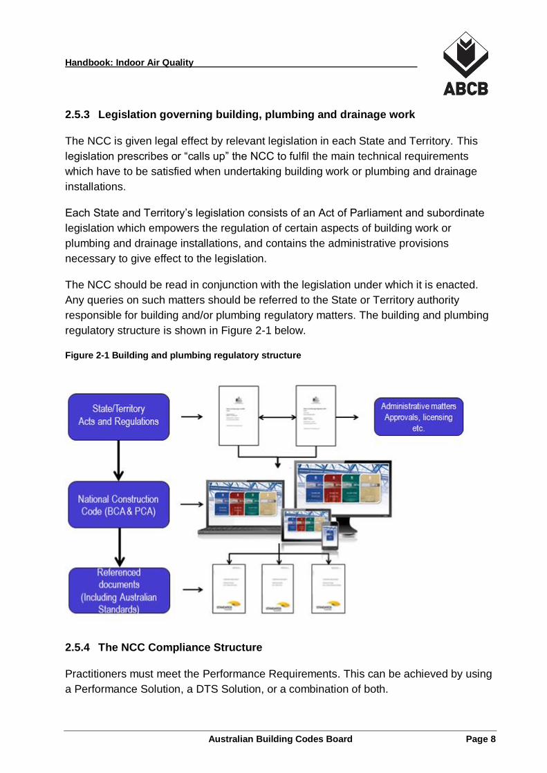
2.5.3 Legislation governing building, plumbing and drainage work
The NCC is given legal effect by relevant legislation in each State and Territory. This
legislation prescribes or “calls up” the NCC to fulfil the main technical requirements
which have to be satisfied when undertaking building work or plumbing and drainage
installations.
Each State and Territory’s legislation consists of an Act of Parliament and subordinate
legislation which empowers the regulation of certain aspects of building work or
plumbing and drainage installations, and contains the administrative provisions
necessary to give effect to the legislation.
The NCC should be read in conjunction with the legislation under which it is enacted.
Any queries on such matters should be referred to the State or Territory authority
responsible for building and/or plumbing regulatory matters. The building and plumbing
regulatory structure is shown in Figure 2-1 below.
Figure 2-1 Building and plumbing regulatory structure
2.5.4 The NCC Compliance Structure
Practitioners must meet the Performance Requirements. This can be achieved by using
a Performance Solution, a DTS Solution, or a combination of both.
Handbook: Indoor Air Quality
Australian Building Codes Board Page 9
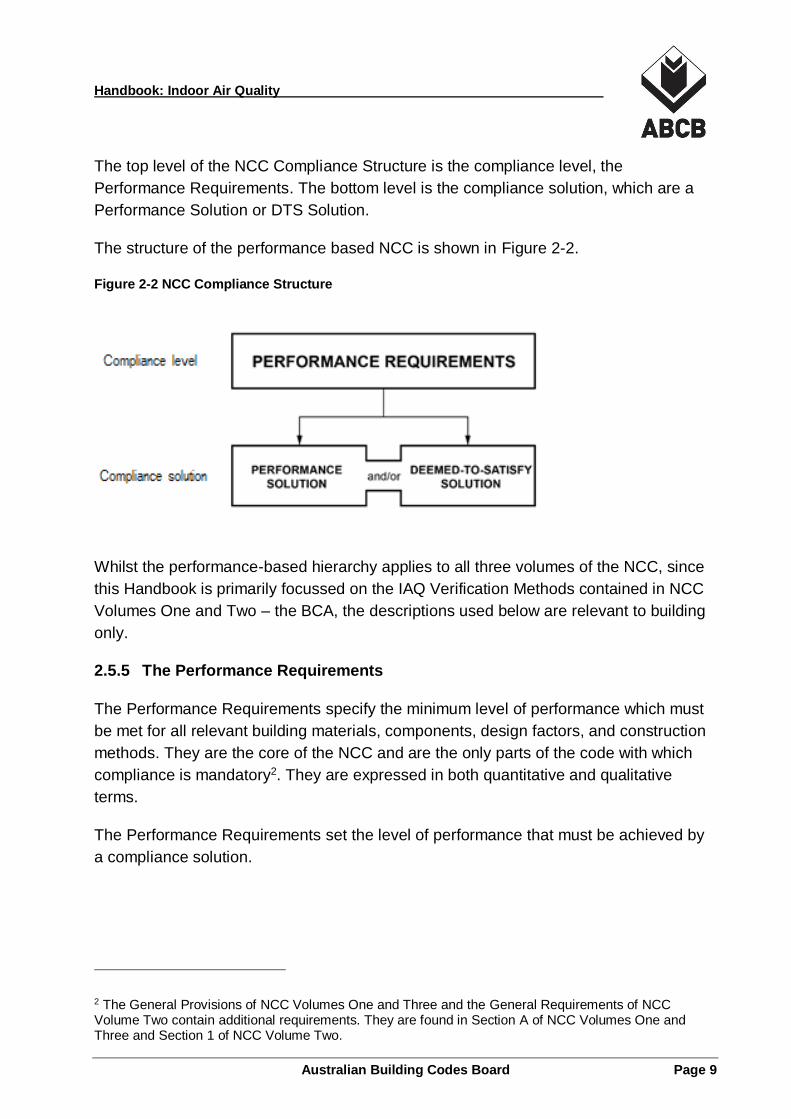
The top level of the NCC Compliance Structure is the compliance level, the
Performance Requirements. The bottom level is the compliance solution, which are a
Performance Solution or DTS Solution.
The structure of the performance based NCC is shown in Figure 2-2.
Figure 2-2 NCC Compliance Structure
Whilst the performance-based hierarchy applies to all three volumes of the NCC, since
this Handbook is primarily focussed on the IAQ Verification Methods contained in NCC
Volumes One and Two – the BCA, the descriptions used below are relevant to building
only.
2.5.5 The Performance Requirements
The Performance Requirements specify the minimum level of performance which must
be met for all relevant building materials, components, design factors, and construction
methods. They are the core of the NCC and are the only parts of the code with which
compliance is mandatory2. They are expressed in both quantitative and qualitative
terms.
The Performance Requirements set the level of performance that must be achieved by
a compliance solution.
2 The General Provisions of NCC Volumes One and Three and the General Requirements of NCC Volume Two contain additional requirements. They are found in Section A of NCC Volumes One and Three and Section 1 of NCC Volume Two.
Handbook: Indoor Air Quality
Australian Building Codes Board Page 10
Alert:
The Objectives and Functional Statements provide guidance as to the intent and
interpretation of the Performance Requirements. They are provided as explanatory
information with the Performance Requirements in the Guide to NCC Volume One and
in Part 2 of NCC Volume Two.
2.5.5.1 Meeting the Performance Requirements
The compliance solutions are the means of satisfying the Performance Requirements.
The NCC provides for different approaches being; a Performance Solution, a DTS
Solution or a combination of these. This is found in the General Requirements of NCC
Volume One in A0.2 and in NCC Volume Two in 1.0.2.
NCC Volume One A0.2 (NCC Volume Two 1.0.2)
The Performance Requirements can only be satisfied by a –
(a) Performance Solution; or
(b) Deemed-to-Satisfy Solution; or
(c) a combination of (a) and (b).
2.5.5.2 DTS Solutions
A DTS Solution uses the DTS Provisions and any referenced documents contained
within the NCC. These provisions include examples of materials, components, design
factors, construction and installation methods which, if followed in full, will result in
compliance with the Performance Requirements of the NCC.
2.5.5.3 Performance Solutions
A Performance Solution is any solution that can meet the Performance Requirements,
other than by a DTS Solution. A Performance Solution may differ in whole or part from
the DTS Provisions, but will still meet the Performance Requirements as long as it can
be successfully demonstrated to the Appropriate Authority how this will be achieved.
When developing a Performance Solution, one or more of the Assessment Methods
contained in the NCC must be used.
Handbook: Indoor Air Quality
Australian Building Codes Board Page 11
2.5.6 Assessment Methods
Assessment Methods are used to determine whether a Performance Solution or DTS
Solution (or a combination of both) complies with the relevant Performance
Requirements.
The following Assessment Methods are listed in the NCC and each, or any combination,
can be used:
Evidence of Suitability;
Verification Methods;
Expert Judgement; or
Comparison with the DTS Provisions.
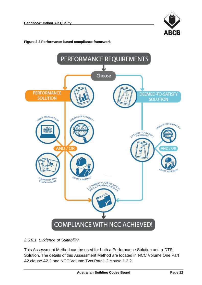
Figure 2-3 outlines the performance-based compliance framework of the NCC.
Handbook: Indoor Air Quality
Australian Building Codes Board Page 12
Figure 2-3 Performance-based compliance framework
2.5.6.1 Evidence of Suitability
This Assessment Method can be used for both a Performance Solution and a DTS
Solution. The details of this Assessment Method are located in NCC Volume One Part
A2 clause A2.2 and NCC Volume Two Part 1.2 clause 1.2.2.
Handbook: Indoor Air Quality
Australian Building Codes Board Page 13
Evidence of suitability can generally be used to support a material, form of construction
or design that satisfies either a Performance Requirement, a DTS Provision, or a
combination of both.
The form of evidence that may be used consists of one, or a combination, of the
following forms:
(a) a report from an Accredited Testing Laboratory or a Registered Testing Authority;
(b) a Certificate of Conformity or a Certificate of Accreditation;
(c) a certificate from a professional engineer or appropriately qualified person;
(d) a current certificate issued by a product certification body that has been accredited
by the Joint Accreditation System of Australia and New Zealand (JAS-ANZ);
(e) any other form of documentary evidence that adequately demonstrates suitability
such as detailed manufacturer’s specifications.
Each volume of the NCC has slightly different evidence of suitability requirements.
Practitioners should refer to the relevant volume of the NCC to clarify what is required.
2.5.6.2 Verification Methods
What is a Verification Method?
In simple terms a Verification Method is a means of demonstrating that a Performance
Solution complies with the relevant Performance Requirement. It may take a number of
forms including a test, inspection, calculation, another method, or a combination of
these.
What is a test?
A test verifies that a certain product or system achieves a certain performance level.
An example of a test to demonstrate compliance with a Performance Requirement
would be an on-site field test to determine the actual thermal performance of a window
installed in a building.
What is an inspection?
An inspection to verify whether a Performance Solution satisfies a Performance
Requirement could include an inspection to ensure that a component is constructed or
installed in a manner that satisfies the Performance Requirement. The inspection may
need to be undertaken by an appropriately qualified person.
Handbook: Indoor Air Quality
Australian Building Codes Board Page 14
What is meant by calculation?
Engineering calculations, including computer modelling, may be able to be used to
verify that a design will achieve a desired result, i.e. meet a Performance Requirement.
What is meant by another method?
Other Verification Methods, by definition, allow almost any methodology or procedure to
be used to verify a Performance Solution, subject to that method being suitable and
used in the appropriate way.
An example of “another” Verification Method may be the use of an overseas code or
standard, noting this must be assessed and approved by the Appropriate Authority as
being appropriate for use. This allows any other suitable method to prove that a design,
construction or individual component meets a Performance Requirement.
The number of possible Verification Methods can be endless depending on the
situation, construction restraints and Performance Requirements to be met.
Due to the broad definition, there are many options available for use as a Verification
Method. However, there must be agreement with the Appropriate Authority on whether
the Verification Method is appropriate.
Ultimately, a Verification Method provides a methodology under which a Performance
Solution can be assessed and generally includes a quantifiable benchmark or
predetermined acceptable criteria that the solution must achieve.
There are two types of Verification Methods that can be used:
the Verification Methods contained in NCC; and
the Verification Methods that the Appropriate Authority accepts for determining
compliance with the Performance Requirements.
2.5.6.3 Expert Judgement
Where physical criteria are unable to be tested or modelled by calculation, the opinion
of a technical expert may be accepted. This is referred to as the use of Expert
Judgement, that is, the judgement of a person who has the qualifications and
experience necessary to determine whether a Performance Solution or DTS Solution
complies with the Performance Requirements.
Handbook: Indoor Air Quality
Australian Building Codes Board Page 15
In some instances, there can be a degree of overlap between Expert Judgement and
other Assessment Methods.
In deciding whether a person is an expert, a number of questions should be asked; and
suggestions on the types of questions are detailed below. This is especially relevant for
the Approval Authority accepting a particular person as an expert even prior to the
subjective judgement being made.
Each situation may be different, so the capacity of the expert to provide credible
evidence in regards to the issue under consideration must be individually assessed.
Who is an expert?
The NCC defines an “expert” in the context of making an Expert Judgement. The NCC
definition of Expert Judgement is the judgement of a person who has the qualifications
and experience to determine whether a Performance Solution or DTS Solution complies
with the NCC Performance Requirement. Therefore the expert must have a high level of
skill and expertise in the particular subject area; enough for them to be considered an
expert on the topic.
Is the person providing the Expert Judgement eligible to be a member of the
relevant association?
There is no specific need for a person to be a member of any relevant organisation or
association. However, where appropriate, the eligibility of a person to be a member may
demonstrate that the person has an appropriate level of qualifications and experience.
This can be used as only one component in determining the appropriateness of a
person to be considered an expert for the purposes of NCC assessment. This is
because the degree of experience and the level of qualification necessary to provide an
expert opinion differ in each case.
Are the qualifications and experience of the person still current and appropriate?
It is important to ensure that the person’s qualifications (when considered appropriate
for the particular circumstance) and experience are still current. A person who has not
been practising for 10 years in the relevant field may be considered inappropriate to
provide Expert Judgement for a specific Performance Solution or DTS Solution. The
appropriate type of experience is one of the major factors that should be used for
determining whether a person is acceptable to be an expert.
Handbook: Indoor Air Quality
Australian Building Codes Board Page 16
Does the person have the appropriate level and type of professional indemnity
insurance?
In many cases, it would be considered prudent to ensure that the person providing the
Expert Judgement has the appropriate level of professional indemnity insurance. In
some States and Territories, legislation requires building practitioners to have this type
of insurance.
2.5.6.4 Comparison with the Deemed-to-Satisfy Provisions
This Assessment Method involves a comparative analysis, which would usually
demonstrate that a Performance Solution is better than, or at least equivalent to, the
DTS Provision(s). To carry out this comparison, the applicable DTS Provision(s) and
Performance Solution would both need to be subjected to the same level of analysis
using the same methodology. This would provide the building designer and Appropriate
Authority with a defined benchmark or level for the DTS Provision(s) and the
Performance Solution.
Following this path, it is possible to determine whether the Performance Solution
provides a similar level of adequate IAQ as that resulting from the use of the DTS
Provisions. In some cases, technical analysis would be carried out using calculation
methods such as computer modelling.
If it is found that the Performance Solution is equal to or better than the DTS Provision,
it can be concluded that the Performance Solution proposal satisfies the NCC
Performance Requirements. In certain circumstance, the Appropriate Authority may also
accept a Performance Solution that is marginally worse than the DTS Provision if the
margin is acceptable to the Authority.
Note also that there is a degree of overlap in the available Assessment Methods.
2.6 NCC Ventilation Performance Requirements
The NCC contains Performance Requirements, Verification Methods and DTS
Provisions for ventilation and IAQ. The Objectives and Functional Statements provide
guidance on the intent of the Performance Requirements.
It is only the Performance Requirements of the NCC that are mandatory and it is these
requirements that building solutions must comply with.
Verification Methods and DTS Provisions are not mandatory but can be chosen as the
compliance pathway for a specific building solution.
Handbook: Indoor Air Quality
Australian Building Codes Board Page 17
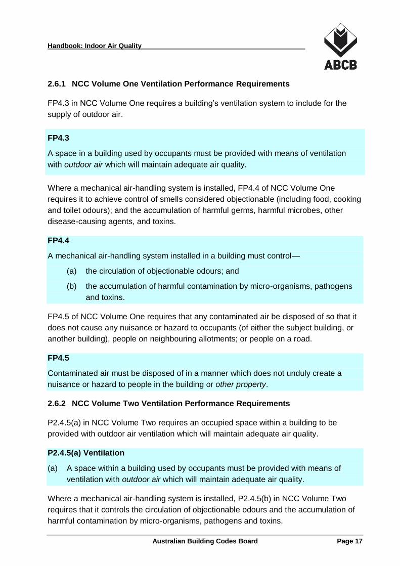
2.6.1 NCC Volume One Ventilation Performance Requirements
FP4.3 in NCC Volume One requires a building’s ventilation system to include for the
supply of outdoor air.
FP4.3
A space in a building used by occupants must be provided with means of ventilation
with outdoor air which will maintain adequate air quality.
Where a mechanical air-handling system is installed, FP4.4 of NCC Volume One
requires it to achieve control of smells considered objectionable (including food, cooking
and toilet odours); and the accumulation of harmful germs, harmful microbes, other
disease-causing agents, and toxins.
FP4.4
A mechanical air-handling system installed in a building must control—
(a) the circulation of objectionable odours; and
(b) the accumulation of harmful contamination by micro-organisms, pathogens
and toxins.
FP4.5 of NCC Volume One requires that any contaminated air be disposed of so that it
does not cause any nuisance or hazard to occupants (of either the subject building, or
another building), people on neighbouring allotments; or people on a road.
FP4.5
Contaminated air must be disposed of in a manner which does not unduly create a
nuisance or hazard to people in the building or other property.
2.6.2 NCC Volume Two Ventilation Performance Requirements
P2.4.5(a) in NCC Volume Two requires an occupied space within a building to be
provided with outdoor air ventilation which will maintain adequate air quality.
P2.4.5(a) Ventilation
(a) A space within a building used by occupants must be provided with means of
ventilation with outdoor air which will maintain adequate air quality.
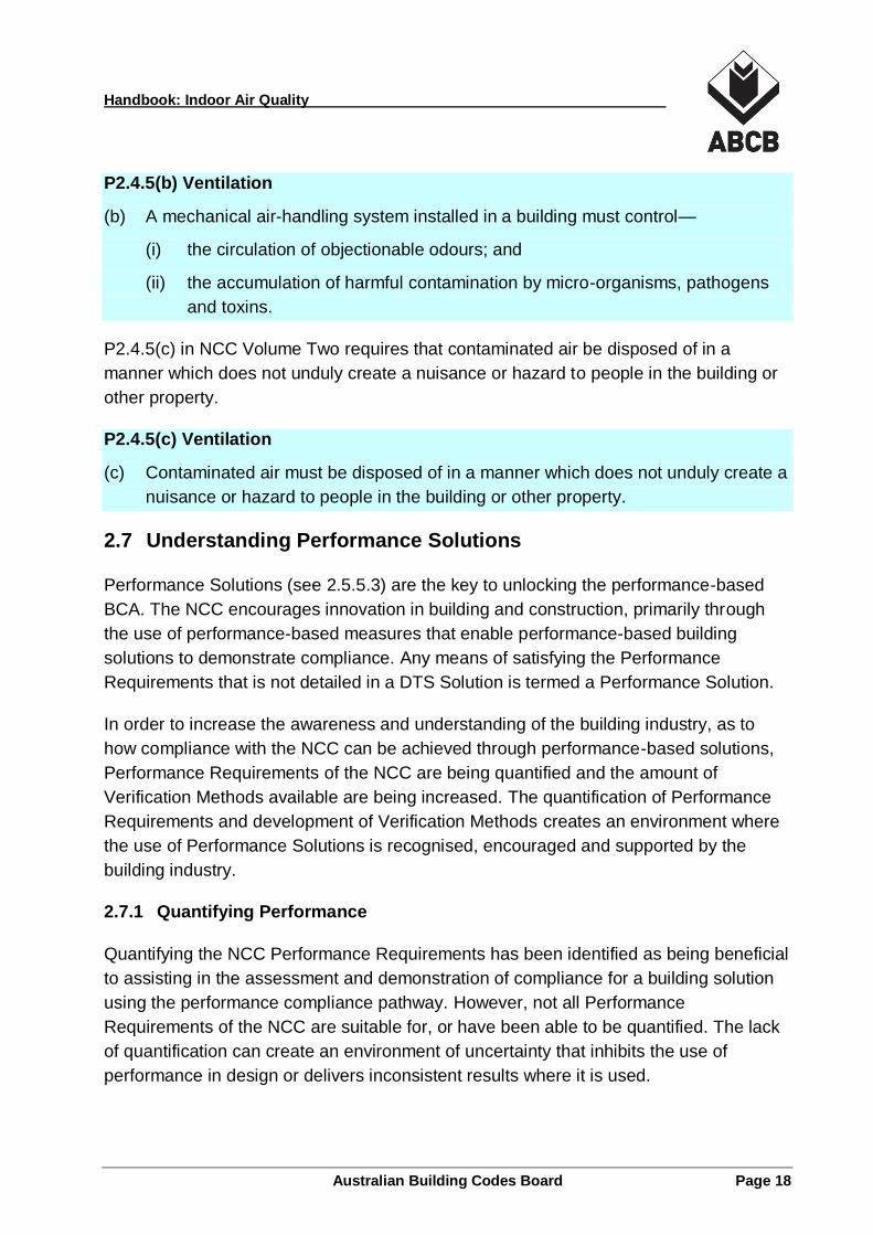
Where a mechanical air-handling system is installed, P2.4.5(b) in NCC Volume Two
requires that it controls the circulation of objectionable odours and the accumulation of
harmful contamination by micro-organisms, pathogens and toxins.
Handbook: Indoor Air Quality
Australian Building Codes Board Page 18
P2.4.5(b) Ventilation
(b) A mechanical air-handling system installed in a building must control—
(i) the circulation of objectionable odours; and
(ii) the accumulation of harmful contamination by micro-organisms, pathogens
and toxins.
P2.4.5(c) in NCC Volume Two requires that contaminated air be disposed of in a
manner which does not unduly create a nuisance or hazard to people in the building or
other property.
P2.4.5(c) Ventilation
(c) Contaminated air must be disposed of in a manner which does not unduly create a
nuisance or hazard to people in the building or other property.
2.7 Understanding Performance Solutions
Performance Solutions (see 2.5.5.3) are the key to unlocking the performance-based
BCA. The NCC encourages innovation in building and construction, primarily through
the use of performance-based measures that enable performance-based building
solutions to demonstrate compliance. Any means of satisfying the Performance
Requirements that is not detailed in a DTS Solution is termed a Performance Solution.
In order to increase the awareness and understanding of the building industry, as to
how compliance with the NCC can be achieved through performance-based solutions,
Performance Requirements of the NCC are being quantified and the amount of
Verification Methods available are being increased. The quantification of Performance
Requirements and development of Verification Methods creates an environment where
the use of Performance Solutions is recognised, encouraged and supported by the
building industry.
2.7.1 Quantifying Performance
Quantifying the NCC Performance Requirements has been identified as being beneficial
to assisting in the assessment and demonstration of compliance for a building solution
using the performance compliance pathway. However, not all Performance
Requirements of the NCC are suitable for, or have been able to be quantified. The lack
of quantification can create an environment of uncertainty that inhibits the use of
performance in design or delivers inconsistent results where it is used.
Handbook: Indoor Air Quality
Australian Building Codes Board Page 19
In some of these instances where Performance Requirements remain unquantified,
Verification Methods have been developed to facilitate the use of the performance
compliance pathway. When building solutions are verified using a Verification Method
then they meet the specific Performance Requirements nominated in the Verification
Method.
2.7.2 Benefits of the Performance Approach
Adopting a performance approach provides the freedom to develop design tools and
methods to optimise building ventilation outcomes. DTS Solutions are prescriptive one-
size-fits-all recipes that are, by their very nature, generally conservative and inflexible.
Taking a more performance and outcomes orientated approach allows the use of new
technologies, new innovations and new materials, which can offer industry greater
flexibility in building design and help produce innovative and cost effective solutions that
can achieve more functional or aesthetically pleasing buildings.
The opportunities and benefits available from the use of the performance approach (in
general and when compared to a DTS approach) include the ability to:
Embrace innovation in technology, design and installation practice;
Deliver flexibility in buildings and building systems;
Optimise energy productivity and minimise energy use in building operations
(potentially for the life of the building);
Save costs in the design or construction of a building; and
Improve the buildability of a building or system.
Essentially the performance approach provides a compliance pathway that allows a
proponent to generate better building outcomes for less cost.
Undertaking the performance approach can attract additional risk factors that need to be
addressed as part of the design, construction and approval phases. In some instances,
these risk factors can act to discourage the use of the Performance Solution compliance
pathway.
2.7.3 Typical Performance Solution Compliance Steps
Typically, the compliance of a building solution as a Performance Solution will require a
series of key steps to establish compliance. The following are the steps recommended
when developing a performance-based proposal:
Handbook: Indoor Air Quality
Australian Building Codes Board Page 20
1. Consult with key stakeholders including the building owner or owner’s
representative.
2. Prepare a performance-based design brief.
3. Carry out any required analysis.
4. Design the solution.
5. Undertake any necessary modelling or testing.
6. Collate and evaluate results.
7. Modify the solution if required.
8. Prepare a final compliance report.
9. Carry out the installation.
10. Document the performance-based building solution.
The compliance report would typically indicate the following information:
the building solution or element that is being assessed;
the Performance Requirements of the NCC that are being met;
a description of the critical issues;
how the NCC Performance Requirements are being achieved in the application; and
a statement on whether compliance is achieved.
2.7.4 Role of Verification Methods
A Verification Method is a test, inspection, calculation or other methodology which
determines whether a building solution complies with the relevant Performance
Requirements, (see 2.5.6.2).
Verification Methods provide an additional means of determining compliance with the
Performance Requirements. They are not mandatory.
Verification Methods are designed to facilitate determination of compliance of a building
solution with the nominated Performance Requirements of the NCC.
A Verification Method can be applied to any building solution but are most commonly
applied to demonstrate compliance of a Performance Solution or where a combination
of compliance pathways is used for a building project.
2.7.5 Benefits of Verification Methods
Verification Methods provide a clear compliance pathway for Performance Solutions.
Handbook: Indoor Air Quality
Australian Building Codes Board Page 21
They can significantly simplify the process of demonstrating compliance and hence can
significantly reduce the costs and complexities of demonstrating compliance.
Verification Methods provide designers with more certainty when developing and
validating Performance Solutions because the system outcomes are predefined. The
methods provide a definitive benchmark for system performance and promote greater
consistency of outcomes across industry practitioners.
Potential disadvantages of Verification Methods include that inputs into verification
models may not be conservative or appropriate in some cases or they may be overly
conservative in other cases. The use of a Verification Method does not guarantee cost
or time savings; it merely facilitates the development and assessment of Performance
Solutions.
Use of the IAQ Verification Methods may provide less design flexibility than a pure
Performance Solution approach might.
Handbook: Indoor Air Quality
Australian Building Codes Board Page 22
3 Building Ventilation
3.1 Building Ventilation Systems
3.1.1 Ventilation
One definition for ventilation is “the deliberate provision of a clean outdoor air supply to
a building or space to meet criteria associated with the use of that space”. Clean
outdoor air is provided to indoor spaces for a number of reasons including:
provide oxygen for human respiration;
dilution or removal of airborne contaminants;
for the correct operation of combustion appliances;
provide for thermal comfort; and
for smoke control or smoke clearance.
Living people metabolise oxygen from the air and this used oxygen needs to be
replaced. Ventilation reduces carbon dioxide build-up caused by human respiration, and
reduces the build-up of odour and other air contaminants in occupied spaces.
Ventilation can be used to remove contaminants at or near their source for disposal to
atmosphere and can assist cooling and comfort needs.
Ventilation can be either natural or mechanical or a combination of the two. The
selection of a building’s ventilation system is largely up to the designer once the
requirements of building regulations have been satisfied.
3.1.2 Natural Ventilation
Natural ventilation can be defined as “ventilation that depends on the naturally occurring
agencies of wind and temperature difference to cause air movement between the inside
and outside of a building, between enclosures within a building and within enclosures”.
Ventilation air is generally delivered through openings of a particular size and
distribution in the external facade of a building. Air moves in and out of these openings
(windows, doors, vents and grilles) and circulates throughout the space being ventilated
through naturally occurring forces (wind, thermal and stack effects). In simple systems
openable windows and doors are relied on to provide access to ventilation. In some
buildings natural ventilation systems are complex and controllable engineered systems.
Handbook: Indoor Air Quality
Australian Building Codes Board Page 23
The minimum requirements that need to be achieved to naturally ventilate a building are
set by the NCC. Where a building or space cannot meet these minimum natural
ventilation requirements then mechanical ventilation is required.
3.1.3 Mechanical Ventilation
Mechanical ventilation can be defined as “ventilation that depends on fans and other air
movement devices to cause air movement between the inside and outside of a building,
between enclosures within a building and within enclosures”. In mechanical ventilation
systems the outdoor air is essentially pumped to where it is needed using fans.
Mechanical ventilation systems are versatile and can be applied to almost any situation
or condition. It provides good control over airflows and an opportunity to filter or clean
outdoor and recirculating air streams. Mechanical ventilation can respond to the varying
needs of occupants and varying indoor pollutant loads and provides a good opportunity
to manipulate building and enclosure pressures.
3.1.4 Hybrid and Mixed-mode Ventilation
Mixed-mode ventilation systems use a combination of the natural and mechanical
ventilation approaches but with independent operation and control between the two
systems (i.e. two separate systems with control integration only).
Hybrid ventilation systems use both natural and mechanical ventilation, or features of
both, in an integrated system. Natural and mechanical ventilation forces can be
combined or operated separately, with the operating mode varying depending on the
needs of the building and occupants at any given time.
3.2 Indoor Air and Indoor Air Contamination
3.2.1 Indoor Air Contaminant Background
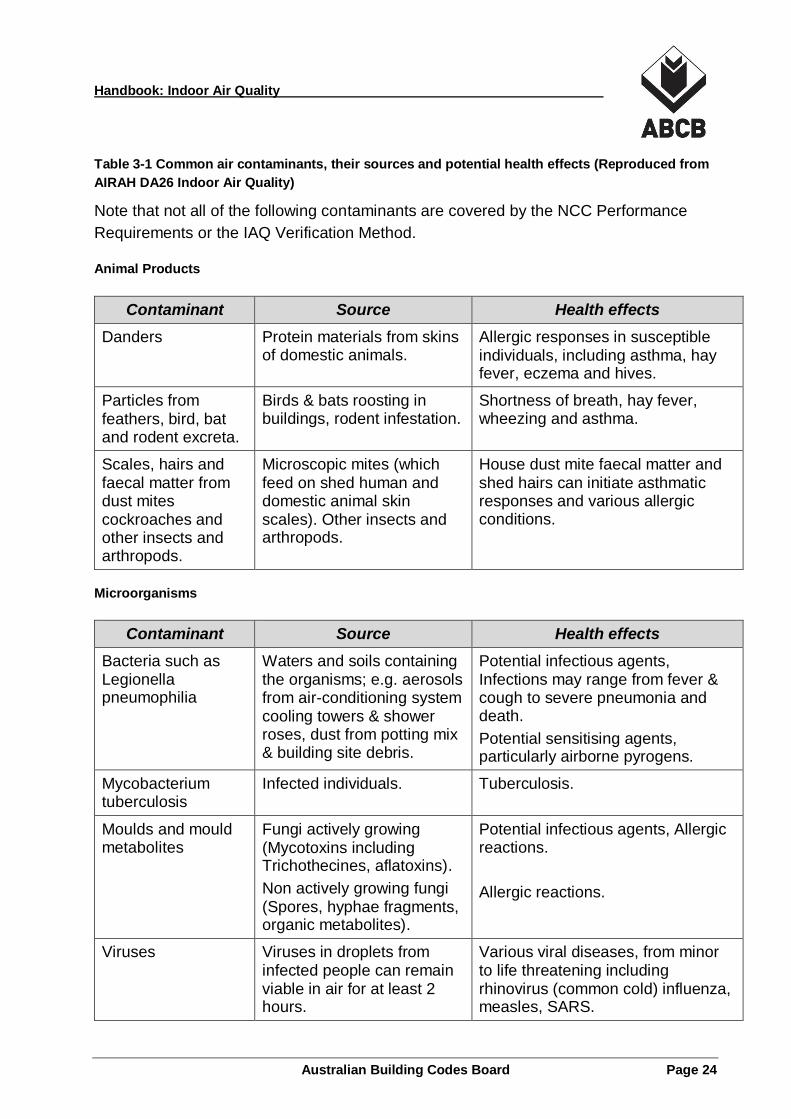
In the indoor environment, people are confronted by a range of contaminants from many
different sources including organic substances such as microorganisms and microbial
debris, pollens, danders and animal hairs, as well as inorganic contaminants such as
metals, fibres, fine particles, and gases. Table 3-1 provides a list of the more common
contaminants found in air, their typical sources and potential health effects (AIRAH
2004).
Handbook: Indoor Air Quality
Australian Building Codes Board Page 24
Table 3-1 Common air contaminants, their sources and potential health effects (Reproduced from
AIRAH DA26 Indoor Air Quality)
Note that not all of the following contaminants are covered by the NCC Performance
Requirements or the IAQ Verification Method.
Animal Products
Contaminant Source Health effects
Danders Protein materials from skins of domestic animals.
Allergic responses in susceptible individuals, including asthma, hay fever, eczema and hives.
Particles from feathers, bird, bat and rodent excreta.
Birds & bats roosting in buildings, rodent infestation.
Shortness of breath, hay fever, wheezing and asthma.
Scales, hairs and faecal matter from dust mites cockroaches and other insects and arthropods.
Microscopic mites (which feed on shed human and domestic animal skin scales). Other insects and arthropods.
House dust mite faecal matter and shed hairs can initiate asthmatic responses and various allergic conditions.
Microorganisms
Contaminant Source Health effects
Bacteria such as Legionella pneumophilia
Waters and soils containing the organisms; e.g. aerosols from air-conditioning system cooling towers & shower roses, dust from potting mix & building site debris.
Potential infectious agents, Infections may range from fever & cough to severe pneumonia and death.
Potential sensitising agents, particularly airborne pyrogens.
Mycobacterium tuberculosis
Infected individuals. Tuberculosis.
Moulds and mould metabolites
Fungi actively growing (Mycotoxins including Trichothecines, aflatoxins).
Non actively growing fungi (Spores, hyphae fragments, organic metabolites).
Potential infectious agents, Allergic reactions.
Allergic reactions.
Viruses Viruses in droplets from infected people can remain viable in air for at least 2 hours.
Various viral diseases, from minor to life threatening including rhinovirus (common cold) influenza, measles, SARS.
Handbook: Indoor Air Quality
Australian Building Codes Board Page 25
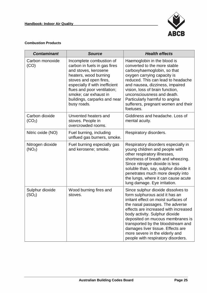
Combustion Products
Contaminant Source Health effects
Carbon monoxide (CO)
Incomplete combustion of carbon in fuels in gas fires and stoves, kerosene heaters, wood burning stoves and open fires, especially if with inefficient flues and poor ventilation; smoke; car exhaust in buildings, carparks and near busy roads.
Haemoglobin in the blood is converted to the more stable carboxyhaemoglobin, so that oxygen carrying capacity is reduced. This can lead to headache and nausea, dizziness, impaired vision, loss of brain function, unconsciousness and death. Particularly harmful to angina sufferers, pregnant women and their foetuses.
Carbon dioxide (CO2)
Unvented heaters and stoves. People in overcrowded rooms.
Giddiness and headache. Loss of mental acuity.
Nitric oxide (NO) Fuel burning, including unflued gas burners, smoke.
Respiratory disorders.
Nitrogen dioxide (NO2)
Fuel burning especially gas and kerosene; smoke.
Respiratory disorders especially in young children and people with other respiratory illnesses, shortness of breath and wheezing. Since nitrogen dioxide is less soluble than, say, sulphur dioxide it penetrates much more deeply into the lungs, where it can cause acute lung damage. Eye irritation.
Sulphur dioxide (SO2)
Wood burning fires and stoves.
Since sulphur dioxide dissolves to form sulphurous acid it has an irritant effect on moist surfaces of the nasal passages. The adverse effects are increased with increased body activity. Sulphur dioxide deposited on mucous membranes is transported by the bloodstream and damages liver tissue. Effects are more severe in the elderly and people with respiratory disorders.
Handbook: Indoor Air Quality
Australian Building Codes Board Page 26
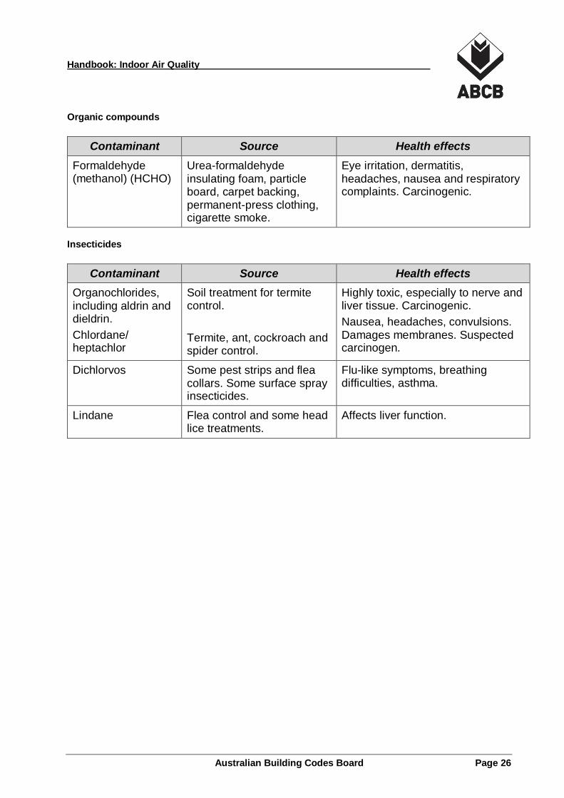
Organic compounds
Contaminant Source Health effects
Formaldehyde (methanol) (HCHO)
Urea-formaldehyde insulating foam, particle board, carpet backing, permanent-press clothing, cigarette smoke.
Eye irritation, dermatitis, headaches, nausea and respiratory complaints. Carcinogenic.
Insecticides
Contaminant Source Health effects
Organochlorides, including aldrin and dieldrin.
Chlordane/ heptachlor
Soil treatment for termite control.
Termite, ant, cockroach and spider control.
Highly toxic, especially to nerve and liver tissue. Carcinogenic.
Nausea, headaches, convulsions. Damages membranes. Suspected carcinogen.
Dichlorvos Some pest strips and flea collars. Some surface spray insecticides.
Flu-like symptoms, breathing difficulties, asthma.
Lindane Flea control and some head lice treatments.
Affects liver function.
Handbook: Indoor Air Quality
Australian Building Codes Board Page 27
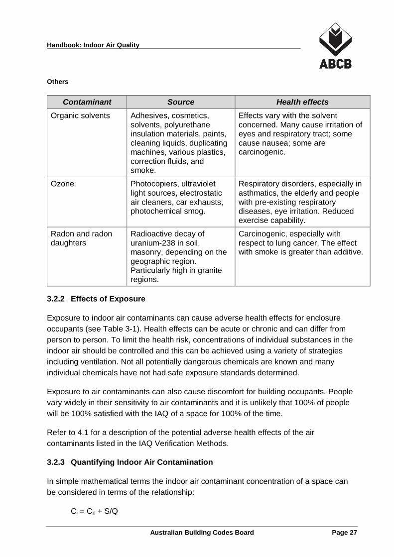
Others
Contaminant Source Health effects
Organic solvents Adhesives, cosmetics, solvents, polyurethane insulation materials, paints, cleaning liquids, duplicating machines, various plastics, correction fluids, and smoke.
Effects vary with the solvent concerned. Many cause irritation of eyes and respiratory tract; some cause nausea; some are carcinogenic.
Ozone Photocopiers, ultraviolet light sources, electrostatic air cleaners, car exhausts, photochemical smog.
Respiratory disorders, especially in asthmatics, the elderly and people with pre-existing respiratory diseases, eye irritation. Reduced exercise capability.
Radon and radon daughters
Radioactive decay of uranium-238 in soil, masonry, depending on the geographic region. Particularly high in granite regions.
Carcinogenic, especially with respect to lung cancer. The effect with smoke is greater than additive.
3.2.2 Effects of Exposure
Exposure to indoor air contaminants can cause adverse health effects for enclosure
occupants (see Table 3-1). Health effects can be acute or chronic and can differ from
person to person. To limit the health risk, concentrations of individual substances in the
indoor air should be controlled and this can be achieved using a variety of strategies
including ventilation. Not all potentially dangerous chemicals are known and many
individual chemicals have not had safe exposure standards determined.
Exposure to air contaminants can also cause discomfort for building occupants. People
vary widely in their sensitivity to air contaminants and it is unlikely that 100% of people
will be 100% satisfied with the IAQ of a space for 100% of the time.
Refer to 4.1 for a description of the potential adverse health effects of the air
contaminants listed in the IAQ Verification Methods.
3.2.3 Quantifying Indoor Air Contamination
In simple mathematical terms the indoor air contaminant concentration of a space can
be considered in terms of the relationship:
Ci = Co + S/Q
Handbook: Indoor Air Quality
Australian Building Codes Board Page 28
Where:
Ci is the indoor air contaminant concentration.
Co is the outdoor air contaminant concentration.
S is a measure of contaminant source generation within the space.
Q is the outdoor air (ventilation) rate.
In terms of this relationship the objective of ventilation systems for contaminant control
is to maintain Ci as close as possible to Co. This can be achieved by maximising the
outdoor airflow rate Q and minimising indoor contaminant generation rate S. The
relationship S/Q is therefore of paramount importance when considering the dilution
performance of ventilation systems.
Additional terms would need to be added to this mathematical model to account for
infiltration and exfiltration, the action of air cleaning devices, and internal sinks removing
contaminants from the air.
The concentration of pollutants in an enclosure is typically affected by the following
factors:
the generation rate of air contaminants indoors;
the level of air contaminants in the regional outdoor air;
the location of outdoor air intake openings relative to local outdoor pollution
sources;
the level of air recirculation employed in a ventilation system;
the level of air cleaning employed; and
the level of contaminants generated within a ventilation system;
3.2.4 Sources of Indoor Air Contaminants
Indoor air contaminants are generated by many diverse sources in buildings, including
the occupants and their activities, the building itself and air contaminants entering with
the incoming outdoor air.
Occupant related air contaminants are due to human respiration, body odour, human
activities, and the processes being carried out by humans in the ventilated space.
Occupant related sources of indoor air contaminants include:
bio effluent from humans;
Handbook: Indoor Air Quality
Australian Building Codes Board Page 29
body odours, skin cells, cosmetics;
equipment use, copying, printing, paper dust etc.;
unflued or natural draft gas fired appliances, such as water and space heaters;
wood burners and other combustion-based space heaters;
processes or activities specific to the building, welding, woodworking, printing etc.;
and
biological contaminants such as bacteria, viruses, fungi, mould, spores, mites, or
pollen.
Non-occupant related sources of air contaminants include the building environment and
the building materials. Furnishings and equipment may also generate air contaminants.
Building related sources of indoor air contaminants include:
the building structure and materials;
the interior furniture and furnishings;
moist or unclean components of the HVAC system;
equipment, computers, and photocopiers not in use; and
cleaning materials and storage areas.
Outdoor air is a potential source of indoor air contaminants. Atmospheric duct is
composed of both inert particles and viable and non-viable biological particles such as
fungal spores, bacteria, and pollens. Outdoor air may also contain organic gases such
as CO, CO2, radon, ozone, SO2, NO2 and VOCs.
3.2.5 Indoor Air Quality (IAQ)
The term “Indoor air quality” (IAQ) means different things to different people and there is
no single accepted definition for it. There are no specific legislated standards for IAQ in
Australia, although there are exposure standards set for a range of chemicals in
industrial environments.
IAQ is a measure or an analysis of the condition of air in an enclosure (a room) and it
includes the physical, chemical and microbiological makeup of the air within and around
buildings and structures, especially as it relates to the health and comfort of building
occupants.
Adding the term “adequate” or “acceptable” to IAQ adds an additional level of
complexity to the analysis, as the expected subjective response of people to the air now
needs to be measured or approximated. Acceptable IAQ includes health and comfort
considerations.

Handbook: Indoor Air Quality
Australian Building Codes Board Page 30
ISO 16814 contains the following definition of Acceptable IAQ: Air in an occupied space
toward which a substantial majority of occupants express no dissatisfaction and that is
not likely to contain contaminants leading to exposures that pose a significant health
risk (ISO 2008).
The NCC ventilation Performance Requirements call for “adequate” air quality. The
minimum acceptable contaminant limits for "acceptable indoor air quality" that verify that
the indoor air is of adequate quality are defined in the IAQ Verification Methods Tables
FV4.1 and FV4.2 from Volume One and Table V2.4.5 from Volume Two.
3.2.6 Indoor Environment Quality (IEQ)
People may perceive problems with ventilation or IAQ as more serious when there are
other factors reducing their indoor comfort such as:
hot or cold air temperatures;
noise or vibration;
ergonomic factors, workstation design, lack of space, poor lighting; or even
work type or load.
Many of these issues could be considered under the heading “Indoor Environment
Quality” (IEQ) of which IAQ and ventilation forms only one, albeit an important, part. The
ASHRAE position paper on indoor air quality provides useful background information on
the relationship between IAQ and other human comfort variables (ASHRAE 2011).
3.3 Outdoor Air and Outdoor Air Contamination
3.3.1 Outdoor Air Contaminants Background
Outdoor air in Australia has the potential to contain a range of pollutants and air
contaminants including both particulates and gases. Common organic gas air
contaminants that may be encountered in the outdoor air include:
Carbon monoxide – from the combustion of fuels.
Sulphur dioxide – from the combustion of sulphur containing fuels, volcanoes.
Nitrogen dioxide – from the combustion of fuels in power stations and vehicles.
Ozone – created in the lower atmosphere by the chemical reactions between
nitrogen oxides, oxygen and VOCs in the presence of sunlight, creating a
photochemical smog including ozone.
Particulate material is also a common air contaminant in the outdoor air.
Handbook: Indoor Air Quality
Australian Building Codes Board Page 31
These outdoor air contaminants are all included in the National Environment Protection
(Ambient Air Quality) Measure (NEPM).
3.3.2 National Standards for Outdoor Air Pollutants in Australia
Most building ventilation systems, including those assessed using the NCC IAQ
Verification Methods, use outdoor air as part of the ventilation strategy. Quantitative
information about local, regional and state outdoor air quality helps ventilation system
designers address the impacts that outdoor air contaminants may have on indoor air
quality.
The underlying assumption on which the NCC Performance Requirements are based is
that the outdoor air in Australia is usually clean and suitable for building ventilation
purposes.
3.3.3 Documenting Australia's Air Quality
Through the National Environment Protection Council, the Australian, State and
Territory Governments agreed to the National Environment and Protection Measure
(NEPM) for Ambient Air Quality (AAQ). The Measure was developed by governments in
consultation with health professionals, environmental groups and the community to
improve the health of Australians through improved outdoor air quality (NEPM 1998).
On 15 December 2015 the National Clean Air Agreement was established to address
reviewing and strengthening air quality monitoring and reporting standards, targeted
measures to reduce emissions from key sources of air pollution, improving access to air
quality information for communities, and fostering partnerships with industry. This was in
response to a review of the NEPM in 2011 (NEPC 2011a).
3.3.4 National Air Quality Standards
The NEPM sets air quality standards that apply throughout Australia. Jurisdictions put
strategies in place to reduce or control emissions in order to achieve the standards. The
standards relate to six specified outdoor air pollutants; carbon monoxide, nitrogen
dioxide, ozone, sulphur dioxide, lead and particles. Five of these are air pollutants that
have maximum contaminant limits specified in the NCC IAQ Verification Methods.
The National Air Quality Standards were set on the basis of scientific studies of air
quality and human health from all over the world, as well as the standards set by
organisations such as the World Health Organization (NEPC 1998, amended 2003).
Australian conditions, e.g. climate, geography and demographics, were taken into
account in estimating the likely exposure of Australians to these major air pollutants.
Handbook: Indoor Air Quality
Australian Building Codes Board Page 32
Each air quality standard has two elements; the maximum acceptable concentration and
the period of time over which the concentration is averaged, see Table 3-2.
Table 3-2 NEPM Ambient Air Quality Standards (Source: NEPC 1998, amended 2003)
Air contaminant Concentration and averaging period
Carbon monoxide 9.0 ppm (parts per million) maximum measured over an eight-hour rolling average period
Nitrogen dioxide 0.12 ppm averaged over a one-hour period
Nitrogen dioxide 0.03 ppm averaged over a one-year period
Ozone 0.10 ppm of ozone measured over a one-hour period
Ozone 0.08 ppm of ozone measured over a four-hour rolling average period
Sulphur dioxide 0.20 ppm averaged over a one-hour period
Sulphur dioxide 0.08 ppm averaged over a 24-hour period
Sulphur dioxide 0.02 ppm averaged over a one-year period
Lead 0.5 µg/m³ (micrograms per cubic meter) averaged over a one-year period
Particles as PM 10 50 µg/m³ averaged over a 24-hour period
Particles as PM 2.5 Advisory reporting standard: 25 µg/m³ over a one-day period; 8 µg/m³ over a one-year period
3.3.5 Monitoring and Reporting
The NEPM includes requirements for individual State and Territory jurisdictions to
monitor and report on performance in reducing the levels of the six specified air
contaminants. The goal is for the standards to be met in all States and Territories with
consistent reporting on levels of air pollution across Australia. Each State and Territory
monitors and publishes data on these six air contaminants.
For the year 2004 (the last NEPM report for all the Jurisdictions of Australia) the quality
of ambient air within the NEPM standards for the six criteria pollutants at all NEPM sites
in Australia was as shown in Table 3-3 (NEPC 2005).
Table 3-3 Ambient air quality at all NEPM sites (within NEPM standards) in 2004
CO NO2 O3 SO2 Lead PM10
No of sites 24 48 54 44 8 59
% of time AAQ Meets NEPM
100% 100% >99.999% >99.999% 100% > 99.995%
Handbook: Indoor Air Quality
Australian Building Codes Board Page 33
Dilution of indoor air contaminants with untreated outdoor air supply is only possible
where the outdoor air quality is equal to, or better than, the NEPM. Table 3-3 shows the
high levels of compliance reached for the minimum outdoor air requirements at all of the
monitoring sites for all of the monitored contaminants. Ambient air quality
measurements suggest that the NEPM carbon monoxide standard is now rarely
exceeded except in circumstances directly adjacent to heavy traffic roads.
Particle counts are typically only exceeded during short-term pollution events such as
smog, bushfires, and sand storms.
Uniform minimum outdoor air conditions provides a platform to use dilution ventilation,
without the need to treat outdoor air, except perhaps for particle filtration, to achieve
minimum acceptable indoor air quality.
3.3.6 Sources of Outdoor Air Contaminants
General and regional sources of outdoor air contaminants are outlined in Table 3-1.
Many of these sources are beyond the control of the building and ventilation system
designers. Local air contaminant sources can be influenced by building layout and
ventilation design decisions. Where the local air quality is poor, outdoor air cleaning or
filtration may be required, prior to use as ventilation air.
Handbook: Indoor Air Quality
Australian Building Codes Board Page 34
4 Indoor Air Contaminant Control
4.1 Air Contaminants to be Verified
Indoor air quality guidelines in buildings are generally developed in consideration of the
occupants that are likely to be exposed. For industrial exposures where the workforce is
expected to be adult, healthy and working for 8 hours a day over 5 days a week the
exposure levels of the Safe Work Australia publication Workplace Exposure Standards
For Airborne Contaminants are appropriate (SWA 2011b).
In public places, offices and homes however, the occupant populations can be expected
to include the very young, the elderly and the infirm and Workplace Exposure Standards
may not be appropriate for these populations. Guidelines for indoor air quality in non-
industrial environments are generally more aligned to ambient air quality standards,
which are typically much more stringent than the Safe Work standards, to account for
this variations in the exposed population.
The IAQ Verification Methods in the NCC specify maximum exposure levels for the
following air contaminants:
Carbon dioxide, CO2
Carbon monoxide, CO
Nitrogen dioxide, NO2
Ozone, O3
Total volatile organic compounds, TVOC
Formaldehyde, CH2O
Particles; PN10 and PM2.5
This section of the Handbook provides a description of each of the nominated indoor air
contaminants, their common sources and health impacts and the background behind
the level specified in the NCC IAQ Verification Methods.
4.1.1 Carbon Dioxide, CO2
4.1.1.1 Description
Carbon dioxide (CO2) is a colourless, odourless and natural chemical component of the
atmosphere that is non-toxic in low concentrations. The background level in air
throughout the world is below 400 ppm. It is unusual to reach much above 400 ppm in
the ambient environment.
Handbook: Indoor Air Quality
Australian Building Codes Board Page 35
4.1.1.2 Health effects
At elevated levels CO2 can cause headaches and may cause changes in respiratory
patterns. Increasing concentrations of 5% to 10 % will lead to dizziness, confusion,
dyspnoea, sweating, dim vision followed by vomiting, disorientation, hypertension, and
ultimately loss of consciousness.
The Worksafe Australia exposure standard for the occupational environment is 5000
ppm which is the 8-hour time weighted average limit for occupational exposures.
Worksafe standards are developed for a presumed fit, adult, working population and are
generally less stringent than ambient or indoor air quality standards or guidelines.
There is some evidence that CO2 levels above 1000 ppm can result in reduced levels of
concentration in humans and reduced productivity levels. That research is ongoing
(ASHRAE 2016).
4.1.1.3 Sources
Natural sources of CO2 include respiration, biological life, decay processes, and
volcanoes. The combustion of fossil fuels is the primary anthropogenic source of CO2 in
the atmosphere. Metabolic processes and combustion devices are the main sources
within indoor environments.
CO2 is formed by the combustion of carbon-containing substances, and important
potential indoor sources include unflued or poorly flued heaters and cooking appliances,
motor vehicle exhaust in enclosed carparks or garages, and environmental tobacco
smoke (note that smoking is not permitted in most non-residential buildings in Australia).
In the absence of combustion devices metabolic processes often dominate as the
primary source of CO2 indoors.
Indoor air CO2 concentrations can only be reliably used as an indicator of acceptable
ventilation of body odour in the absence of significant indoor sources of the gas that are
not related to respiration (e.g. combustion processes).
4.1.1.4 Principles behind the maximum contaminant limit specified
Although not a contaminant of health concern in most buildings, CO2 levels are often
monitored as an indicator of building occupancy and the associated concentration of
human bio effluent. The IAQ Verification Methods specify a CO2 maximum contaminant
limit of:
850 ppm Averaged over 8 hours.
Handbook: Indoor Air Quality
Australian Building Codes Board Page 36
Typical CO2 level limits and recommendations for a range of purposes are indicated in
Table 4-1.
Table 4-1 Various CO2 level limits and recommendations
Comments CO2 concentration
(ppm)
Australian occupational exposure limit (SWA 2011b) 5000
ASHRAE 62.1 recommendation (occupant comfort) 1000
AS 1668.2 recommendation (for CO2 controlled ventilation) 800 - 600
NCC IAQ Verification Method (as an indicator for body odour)
850
Typical outdoor air range 400 - 300
Because CO2 is used as a measure for body odour in the IAQ Verification Methods the
contaminant limit is not based on the occupational exposure health limit of 5000 ppm.
The maximum contaminant limit has been set at a CO2 level of 850 ppm over an 8-hour
period which is based on a 450 ppm rise above an assumed ambient CO2 level of 400
ppm. This represents what is considered to be an adequately ventilated building from an
occupant “odour amenity” point of view.
4.1.2 Carbon Monoxide, CO
4.1.2.1 Description
Carbon monoxide (CO) is a colourless, odourless, poisonous gas that is a by-product of
incomplete combustion. The natural concentration of carbon monoxide in outdoor air is
around 0.2 parts per million (ppm). Larger cities have the potential to have higher levels
of carbon monoxide due to emissions from vehicle traffic and industrial processes. The
NEPM maximum concentration of CO allowed in outdoor air is 9 ppm (NEPM 1998).
4.1.2.2 Health effects
CO adversely affects both healthy and unhealthy people. When inhaled, it readily mixes
with haemoglobin in the blood, inhibiting the blood's ability to carry and exchange
oxygen. Once more than 2.5% of haemoglobin is bound to carbon monoxide health
effects become noticeable. High concentrations can cause headaches, fatigue,
confusion, and drowsiness. Prolonged and repeated exposure can affect the heart.
At very high concentrations of carbon monoxide, up to 40% of the haemoglobin can be
bound to carbon monoxide in this way. This very high concentration will almost certainly
Handbook: Indoor Air Quality
Australian Building Codes Board Page 37
kill. People with heart problems, children and unborn babies are particularly at risk. CO
does not readily leave the body once it enters.
Refer to AS 1668.2-2012 Appendix H for a detailed commentary on CO exposures in
occupational environments and the resulting blood carboxyhaemoglobin (COHb) levels
(Standards Australia 2012a).
Given that there have been deaths in Australian buildings from exposure to carbon
monoxide indoors, and the very significant number of people potentially exposed to it,
CO is considered an indoor pollutant of significant health concern.
4.1.2.3 Sources
Natural sources of CO include volcanoes and bushfires. Anthropogenic sources include
the burning of fossil fuels for power generation, motor vehicle exhaust, petrol and metal
refining, other manufacturing industries and food processing.
CO can be generated indoors by burning cigarettes and incense, internal combustion
engines, oil or gas fired boilers, furnaces, stoves and water heaters, wood heaters, solid
fuel stoves etc. Improperly flued or under-ventilated combustion devices present the
highest risks.
4.1.2.4 Principles behind the maximum contaminant limit specified
The maximum contaminant limits for CO specified in the IAQ Verification Methods are:
For a Class 2, 3, Class 4 part, Class 5, 6, 9b or 9c building:
90 ppm Averaged over 15 minutes*
50 ppm Averaged over 30 minutes
25 ppm Averaged over 1 hour*
10 ppm Averaged over 8 hours*
For a Class 7a building:
100 ppm Never to be exceeded
90 ppm Averaged over 15 minutes
60 ppm Averaged over 1 hour
30 ppm Averaged over 8 hours**
The less stringent requirements for a Class 7a building reflects the increased CO
contaminant generation rates in these buildings, due to the unavoidable operation of
Handbook: Indoor Air Quality
Australian Building Codes Board Page 38
internal combustion engines, and the transient nature of occupants within this class of
building.
These maximum contaminant limits are generally consistent with or more stringent than
the *WHO Guidelines (WHO 2010) and **Australian occupational exposure limits set by
Safe Work Australia (SWA 2011).
4.1.3 Nitrogen Dioxide, NO2
4.1.3.1 Description
Nitrogen dioxide (NO2) is a malodourous, suffocating, brownish, oxidising gas that
reacts in the air to form corrosive nitric acid, as well as toxic organic nitrates. It plays a
major role in the atmospheric reactions that produce ground-level ozone and smog.
4.1.3.2 Health effects
NO2 can cause headaches, irritation to the eyes, nose and throat and can cause lung
congestion and respiratory problems. There is evidence that it suppresses the body’s
immune system. Prolonged and repeated contact can lead to low blood pressure and an
increased risk of infection. People with asthma and people with heart disease are most
at risk.
4.1.3.3 Sources
NO2 is formed naturally in the atmosphere by lightning and some is produced by plants,
soil and water. However, most NO2 found in the outdoor air is as a result of road traffic
vehicle exhaust and other fossil fuel combustion processes.
The sources of NO2 in outdoor air are much the same as for CO. Major sources include
the burning of fossil fuels for power generation, motor vehicle exhaust, petrol and metal
refining, other manufacturing industries and food processing. Up to 80% of the NO2 in
cities comes from motor vehicle exhaust. In sunlight, nitric oxide rapidly changes into
NO2.
Unflued gas heaters and cookers are the major sources of NO2 indoors as well as
potential transport of the contaminant from attached garages and carparks.
4.1.3.4 Principles behind the maximum contaminant limit specified
The maximum contaminant limits for NO2 specified in the IAQ Verification Methods are:
40 μg/m³ (0.0197 ppm) Averaged over 1 year; and
Handbook: Indoor Air Quality
Australian Building Codes Board Page 39
200 μg/m³ (0.0987 ppm) Averaged over 1 hour.
These limits were adopted from the WHO air quality guidelines for NO2, set to protect
the public from effects on health of nitrogen dioxide gas itself. The limit is not designed
to address combustion related co-pollutants of NO2, (WHO 2010).
4.1.4 Ozone, O3
4.1.4.1 Description
Ozone (O3) is a colourless gas with a distinctive “electric” smell. Ozone is present in
both the stratosphere (upper atmosphere) and the troposphere (lower atmosphere).
Stratospheric ozone is not a pollutant and is called the “ozone layer” because it protects
organic life on the planet by reducing the levels of damaging UV-B radiation reaching
the Earth's surface. Ground level ozone on the other hand is considered an air pollutant
because it is harmful to human health and the environment.
Ozone concentrations in Australia tend to be lower indoors in buildings than outdoors.
This is because Australian buildings generally have limited indoor sources of ozone and
the effectiveness of interior furnishings and the building fabric in removing ozone from
the air.
4.1.4.2 Health effects
Ozone can irritate the eyes, nose, throat and lungs and can cause allergic reaction in
sensitised individuals and exacerbation of asthma.
Exposure to elevated concentrations of ozone increases risk from respiratory irritation
and changes in lung function, particularly for people that already suffer from a
respiratory illness (WHO 2006).
4.1.4.3 Sources
Ground level or tropospheric ozone is formed in the lower atmosphere when ozone
precursors, typically oxides of nitrogen (NOx), carbon monoxide, and volatile organic
compounds (VOCs) react in warm, sunny conditions. Anthropogenic sources of these
ozone precursors include emissions from industrial facilities, electric power stations,
motor vehicle exhausts, fumes from engines, as well as emissions from paints, aerosols
and solvents.
Handbook: Indoor Air Quality
Australian Building Codes Board Page 40
Natural sources of ozone precursors include eucalyptus trees, (which contribute
significant emissions of volatile organic compounds), bushfire and hazard reduction
events, which can all have an impact on local ozone concentrations.
Indoors, ozone is generated by high voltage electrical equipment such as photocopiers,
laser printers and by ozone-generating air-cleaning devices.
4.1.4.4 Principles behind the maximum contaminant limit specified
The maximum contaminant limits for ozone specified in the IAQ Verification Methods is
100 μg/m³ An 8 hour daily maximum limit.
This limit was adopted from the WHO guidelines. This concentration will provide
adequate protection of public health, though some health effects may occur below this
level for sensitive individuals (WHO 2006).
4.1.5 Total Volatile Organic Compounds, TVOC
4.1.5.1 Description
Volatile Organic Compounds (VOC) are carbon containing compounds that evaporate at
room temperature. This means they have a high enough vapour pressure to vaporise
from materials and surfaces into the indoor air at normal room temperatures, a process
known as off-gassing.
VOCs are a diverse class of compounds that include alkanes, aromatics, aldehydes,
ketones, alcohols and ethers. There can be many of these contaminants in indoor air.
They are usually present as complex mixtures of many compounds at low
concentrations, and there are up to several hundred different compounds that can
potentially be found in low concentrations in the indoor environment. When considered
as a whole and in combination they are termed “Total” VOCs or TVOC.
Semi volatile organic compounds (SVOCs) are a subgroup of VOCs that tend to have a
higher molecular weight and higher boiling point temperature than other VOCs. All
indoor VOCs are present partly as gaseous airborne chemicals and partly as chemicals
that are adsorbed onto indoor surfaces and particles, settled or airborne. In many cases
a large fraction of the SVOCs in a space are present on surfaces and settled particles
and only a small fraction are present as a gas or on airborne particles. Increased
ventilation may not be highly effective in reducing local concentrations of SVOCs
because these higher molecular weight VOCs are present mostly on indoor surfaces
and not in the air.
Handbook: Indoor Air Quality
Australian Building Codes Board Page 41
4.1.5.2 Health effects
In outdoor air VOCs are a health concern because they are an integral part of the
reaction system that leads to the formation of photochemical smog pollution.
In indoor air VOCs may cause eye and upper respiratory irritation, nasal congestion,
headache, and dizziness. Most individual VOCs are probably not present at a sufficient
concentration indoors to cause these sensory irritation symptoms themselves. However,
mixtures of multiple VOCs, that can include specific highly irritant VOCs that are
produced by indoor chemical reactions, appear likely to be sources of irritation to
occupants in buildings. VOCs can react with oxidants such as ozone and possibly
nitrogen oxide and nitrogen dioxide to form reactive species and strong irritants,
including various acids and aldehydes.
A number of the VOCs that are found in indoor air, have been shown to cause cancer in
animals when exposed to high concentrations. A few of these VOCs, for example,
formaldehyde and benzene, are considered to cause cancer in humans however the
magnitude of the cancer risks currently have a high level of uncertainty (IARC 2012).
The health effects depend on the specific composition of the VOCs present and the
length of human exposure. Some people can become sensitised to VOCs and react to
extremely low concentrations in subsequent exposures. The cumulative exposure to
several compounds at low concentrations, or the synergistic effects, may also have an
impact on the strength and nature of individual reactions.
4.1.5.3 Sources
VOCs are released from most materials, whether synthetic or natural. VOC emissions
are released at room temperature from materials or products in the form of gases.
Sources include new materials such as office furnishings, adhesives, paints, caulking,
fillers, pressed wood products, carpets and underlays, stored supplies, printers and
photocopiers, electrical equipment, cosmetics, cleaning products, and personal hygiene
products.
Many VOCs come from the solvents that are used in products for a variety of purposes
including as solvents in chemical strippers, clothing- and furniture-cleaners and as
carriers for polishes, paints, and varnishes. Wet applied products such as adhesives,
paints, fillers and sealants commonly contain volatile organic solvents that are released
during and immediately after application while the product dries and cures. Solvents are
also inherent in many personal grooming products, including cleaners, disinfectants,
deodorizers, and perfumes.
Handbook: Indoor Air Quality
Australian Building Codes Board Page 42
There is also potential for a long-term slow release of VOCs from residual solvents as
well as the gradual production of new air contaminants due to species degradation. The
highest VOC emissions tend to occur when products are new, and especially if the
products are applied wet, such as paints, adhesives or sealants. Long-term emissions
(i.e. for periods greater than several months), tend to occur from thicker materials such
as building fabric materials, floor coverings and furniture.
Soft materials and furnishings can adsorb VOCs from the air when local emission rates
and local concentrations are high and then re-emit the VOCs to the indoor air at a later
time.
4.1.5.4 Principles behind the maximum contaminant limit specified
The maximum contaminant limits for TVOC specified in the IAQ Verification Methods is
500 μg/m³ Averaged over one hour.
This limit was adopted from the NHMRC recommended Interim National Indoor Air
Quality Goals that were rescinded in March 2002 (but are still available) (NHMRC 1996
rescinded 2002).
4.1.6 Formaldehyde, CH2O
4.1.6.1 Description
Formaldehyde is a colourless strong smelling gas and is one of the most commonly
encountered indoor VOC. Formaldehyde is typically generated indoors due to off-
gassing from a variety of common building materials such as particleboard, fibreboard
and plywood. In general, concentrations of formaldehyde indoors typically exceed
outdoor concentrations.
Formaldehyde is present in the outdoor air at natural background levels of about 0.03
ppm with concentrations up to 0.08 ppm in outdoor urban air. The contribution of
formaldehyde air contaminants in indoor air from the outdoor air appears to be minimal.
Formaldehyde is an industrially significant substance with the widespread downstream
use of formaldehyde based inputs including synthetic resins, industrial chemicals,
preservatives, and in the production of paper, textiles, cosmetics, disinfectants,
medicines, paints, varnishes and lubricants.
Handbook: Indoor Air Quality
Australian Building Codes Board Page 43
4.1.6.2 Health effects
Formaldehyde is a VOC that can cause irritation of the eye, nose and throat and lower
respiratory tract, and an inflammatory response in the airways. The evidence of a
linkage of formaldehyde with allergies, asthma, and respiratory effects is most
extensive.
Formaldehyde is considered to cause cancer in humans (IARC 2006).
4.1.6.3 Sources
Formaldehyde occurs naturally in the environment and is emitted by processes such as
combustion, decay and is emitted naturally by all timber species. Formaldehyde is also
present in exhaust fumes, wood smoke, and is produced by domestic appliances such
as combustion heaters. The outdoor air is a source of formaldehyde but the primary
sources are in the indoor environment itself; building materials, insulation materials,
finishing materials, combustion appliances, tobacco smoke, and a large variety of
consumer products.
The superior bonding properties and low cost of formaldehyde polymers make them
common resins that are used in the production of many building materials.
Formaldehyde polymers are used in the manufacture of floor coverings, and
formaldehyde resins are also used in the textile industry as binders, fire retardants, or to
impart stiffness, wrinkle resistance, and water repellence to fabrics.
Fertilisers and pesticides used for indoor plants can contain aldehydes. Gas-fired stoves
and heaters can also emit formaldehyde. Formaldehyde is used in numerous work
places, such as biological laboratories, hospitals, and hobby and craft areas.
4.1.6.4 Principles behind the maximum contaminant limit specified
The maximum contaminant limits for formaldehyde specified in the IAQ Verification
Methods is:
0.1 mg/m3 Averaged over 30 minutes
This limit was adopted from the WHO guidelines as the recommended level to prevent
sensory irritation in the general population (WHO 2010).
Handbook: Indoor Air Quality
Australian Building Codes Board Page 44
4.1.7 Particulate Matter, PM
4.1.7.1 Description
Airborne particles are generally referred to as particulate matter or simply PM.
Particulates can include dust, dirt, soot, smoke, and liquid droplets and can vary in size
and visibility. Particles are classified on the basis of their size, their aerodynamic
diameter:
Coarse particles are those between 10 and 2.5 micrometres (µm) in diameter;
Fine particles are smaller than 2.5 µm; and
Ultrafine particles are smaller than 0.1 µm.
Particles can also be classified according to their chemical composition. The health
impacts of particulate air contaminants are dependent on both their size and their
chemical composition (WHO 2006).
4.1.7.2 Health effects
Even relatively low concentrations of particle pollution can cause health impacts in
some individuals (WHO 2006). The concentration and size of the particles are also
important and these can vary greatly between sources, regions and seasons.
Respiration of particles challenges the body’s natural defence mechanisms and
overexposure may strain these mechanisms, causing an adverse reaction.
Inhalable particles are typically defined as:
PM10 - particles with an aerodynamic diameter of 10 micrometres or smaller;
PM2.5 - particles with an aerodynamic diameter of 2.5 micrometres or smaller.
In general terms, the smaller the particle the greater its impact on human health. PM2.5
are respirable particles, i.e. they bypass the body’s natural defence mechanisms more
readily and can make their way deep into the lungs.
Respirable particles may give rise to irritation of the eyes, nose, throat and respiratory
tract, coughs, bronchitis, asthma and other lung conditions, respiratory diseases and
allergic responses, exacerbation of respiratory and cardiopulmonary diseases, and lung
cancer. Some particles are small enough to pass into the bloodstream through the finest
blood vessels of the lungs where they can trigger heart attacks (HEI 2013).
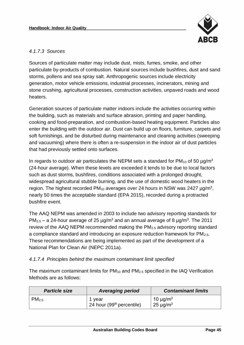
Handbook: Indoor Air Quality
Australian Building Codes Board Page 45
4.1.7.3 Sources
Sources of particulate matter may include dust, mists, fumes, smoke, and other
particulate by-products of combustion. Natural sources include bushfires, dust and sand
storms, pollens and sea spray salt. Anthropogenic sources include electricity
generation, motor vehicle emissions, industrial processes, incinerators, mining and
stone crushing, agricultural processes, construction activities, unpaved roads and wood
heaters.
Generation sources of particulate matter indoors include the activities occurring within
the building, such as materials and surface abrasion, printing and paper handling,
cooking and food-preparation, and combustion-based heating equipment. Particles also
enter the building with the outdoor air. Dust can build up on floors, furniture, carpets and
soft furnishings, and be disturbed during maintenance and cleaning activities (sweeping
and vacuuming) where there is often a re-suspension in the indoor air of dust particles
that had previously settled onto surfaces.
In regards to outdoor air particulates the NEPM sets a standard for PM10 of 50 µg/m3
(24-hour average). When these levels are exceeded it tends to be due to local factors
such as dust storms, bushfires, conditions associated with a prolonged drought,
widespread agricultural stubble burning, and the use of domestic wood heaters in the
region. The highest recorded PM10 averages over 24 hours in NSW was 2427 µg/m3,
nearly 50 times the acceptable standard (EPA 2015), recorded during a protracted
bushfire event.
The AAQ NEPM was amended in 2003 to include two advisory reporting standards for
PM2.5 – a 24-hour average of 25 µg/m3 and an annual average of 8 µg/m3. The 2011
review of the AAQ NEPM recommended making the PM2.5 advisory reporting standard
a compliance standard and introducing an exposure reduction framework for PM2.5.
These recommendations are being implemented as part of the development of a
National Plan for Clean Air (NEPC 2011a).
4.1.7.4 Principles behind the maximum contaminant limit specified
The maximum contaminant limits for PM10 and PM2.5 specified in the IAQ Verification
Methods are as follows:
Particle size Averaging period Contaminant limits
PM2.5 1 year 24 hour (99th percentile)
10 μg/m3 25 μg/m3
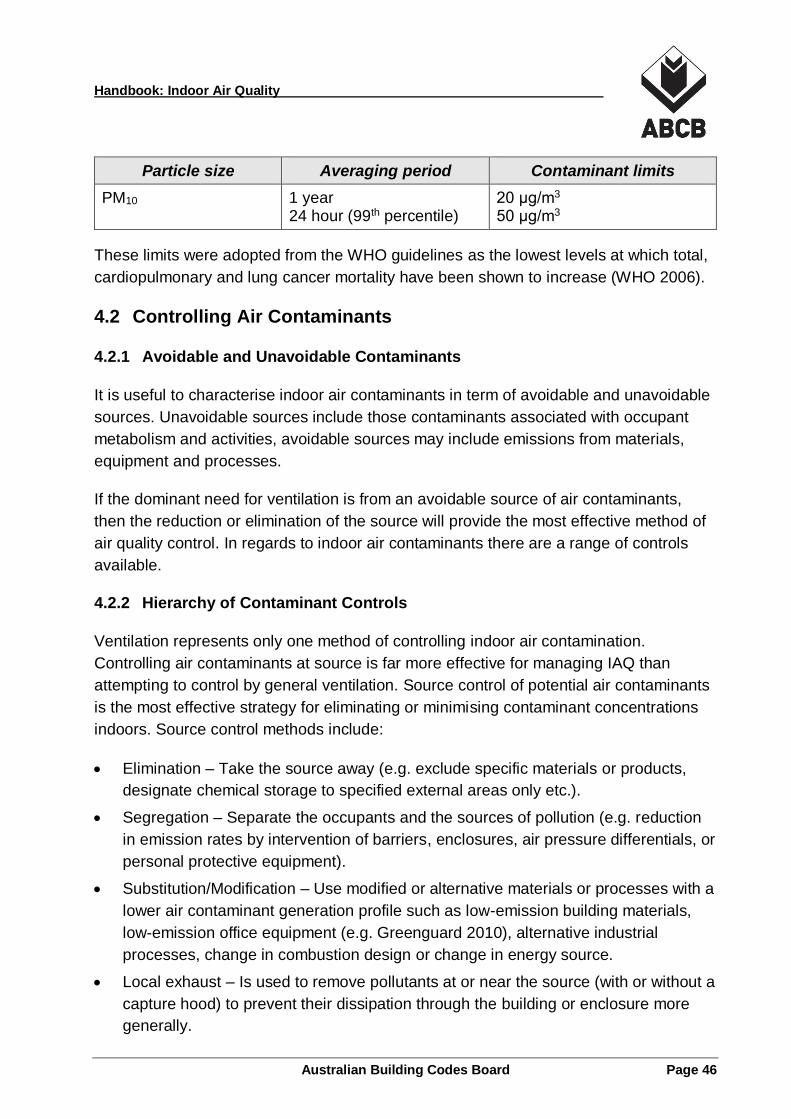
Handbook: Indoor Air Quality
Australian Building Codes Board Page 46
Particle size Averaging period Contaminant limits
PM10 1 year 24 hour (99th percentile)
20 μg/m3 50 μg/m3
These limits were adopted from the WHO guidelines as the lowest levels at which total,
cardiopulmonary and lung cancer mortality have been shown to increase (WHO 2006).
4.2 Controlling Air Contaminants
4.2.1 Avoidable and Unavoidable Contaminants
It is useful to characterise indoor air contaminants in term of avoidable and unavoidable
sources. Unavoidable sources include those contaminants associated with occupant
metabolism and activities, avoidable sources may include emissions from materials,
equipment and processes.
If the dominant need for ventilation is from an avoidable source of air contaminants,
then the reduction or elimination of the source will provide the most effective method of
air quality control. In regards to indoor air contaminants there are a range of controls
available.
4.2.2 Hierarchy of Contaminant Controls
Ventilation represents only one method of controlling indoor air contamination.
Controlling air contaminants at source is far more effective for managing IAQ than
attempting to control by general ventilation. Source control of potential air contaminants
is the most effective strategy for eliminating or minimising contaminant concentrations
indoors. Source control methods include:
Elimination – Take the source away (e.g. exclude specific materials or products,
designate chemical storage to specified external areas only etc.).
Segregation – Separate the occupants and the sources of pollution (e.g. reduction
in emission rates by intervention of barriers, enclosures, air pressure differentials, or
personal protective equipment).
Substitution/Modification – Use modified or alternative materials or processes with a
lower air contaminant generation profile such as low-emission building materials,
low-emission office equipment (e.g. Greenguard 2010), alternative industrial
processes, change in combustion design or change in energy source.
Local exhaust – Is used to remove pollutants at or near the source (with or without a
capture hood) to prevent their dissipation through the building or enclosure more
generally.
Handbook: Indoor Air Quality
Australian Building Codes Board Page 47
Air cleaning – Can be used to remove particles or gaseous air contaminants or
both, generated either locally or in an area or region, from the air using an air
cleaning device.
Education – To change or modify occupant behaviour or ensure correct operation
and maintenance by the system operator or user. Education can include consumer
information on products and materials, information on health, soiling, productivity,
and nuisance effects of materials, information on legal rights and liabilities related to
indoor quality, as well as real time IAQ data displayed from the building control
system.
4.2.3 Air Contaminant Balance
Any consideration or analysis of indoor air contaminant concentrations generally
devolves to a steady state consideration of the mass-balance of all contaminant outputs
and inputs within the boundaries of the analysis.
The boundaries of the analysis are generally the walls, floors and ceiling of the space
under consideration. The analysis must consider all the interactions within the volume
encompassed by the boundaries and all movement across them.
The contaminant inputs are all of the air contaminants that are being added to the space
through outdoor air, indoor occupants and materials, indoor activities and processes,
and the HVAC system or its components.
The contaminant outputs are all of the air contaminants that are being removed from the
space through exhaust or spill air, the actions of air filters and cleaners, the absorption
of contaminants into indoor materials, and species degradation and chemical reactions
within the space air.
4.3 Indoor Air Contaminant Control Strategies
The most common design strategies that are utilised to control indoor air contaminant in
buildings are:
Limit the use of materials and products that emit specific air contaminants;
Remove unflued combustion heating from all internal areas of the building;
Ventilate all unflued combustion cooking devices or areas in the building;
Seal the building from uncontrolled infiltration and exfiltration of air;
Locally ventilate any fixed contaminant generation points;
Optimise air distribution systems for contaminant control;
Handbook: Indoor Air Quality
Australian Building Codes Board Page 48
Remove contaminants from the air with air cleaners;
Ventilate the space with clean outdoor air;
Manage the construction with an IAQ plan; and
Manage the facility with an IAQ plan.
Further detail on each of these strategies is provided in this section of the Handbook.
4.3.1 Limit Contaminant Emitting Materials
Many building materials, finishes and furnishings can emit air contaminants such as
formaldehyde gas and other VOCs into the indoor air. In some cases, emissions occur
for many years after manufacture or installation. One of the most effective ways to limit
these air contaminants is to limit the use of the materials and products that emit them.
It is difficult for material specifiers and other decision makers to identify low-emission
materials when there are no clear standards, goals or guidelines and inadequate
information available on the air contaminants that may be emitted by a product. In many
cases, sourcing the manufacturer’s product data is the first step in the process.
Manufacturers do produce safety data sheets (SDS), also called material safety data
sheets (MSDS) outlining the properties of their products, the materials used and the
associated hazards, including instructions for handling, storage and disposal. These
sheets do not generally indicate the air contaminant emissions profile of a product, but
material and ingredient lists can be used to identify potential air contaminant issues.
There are however an increasing number of schemes and organisations that do specify
emission limits of VOCs (and other air contaminants) for building materials and finishes,
for interior furnishings and for indoor equipment. This is resulting in an increasing
number of low-emission products and materials coming to the market that are now
available for designers and contractors to use in the construction of buildings.
Appendix B provides a list of some data sources for more information on selecting low-
emission materials for buildings.
4.3.2 Limit Indoor Combustion Devices
Indoor combustion devices can generate a number of air contaminants including
nitrogen dioxide, carbon monoxide, respirable particles, nitrosamines, and polynuclear
aromatic hydrocarbons. These air contaminants can be generated in many indoor
locations, such as restaurants, cafeterias, homes, hotels, enclosed carparks, buildings
with attached garages, and recreational facilities that use equipment with internal
combustion engines.
Handbook: Indoor Air Quality
Australian Building Codes Board Page 49
The application of indoor combustion devices for space or water heating, or the use of
internal combustion engines indoors should be reconsidered in a design targeting low-
air contaminant characteristics. Options include the removal of internally located unflued
combustion heating devices from the design and the provision of exhaust ventilation to
all unflued combustion cooking devices and all cooking areas. The use of electricity or
solar thermal energy for space and water heating produces no indoor air pollutants
directly, whereas heating by an unflued combustion device can increase indoor levels of
nitrogen dioxide, carbon monoxide, other combustion gases and particles. Some
heaters can emit formaldehyde as a product of inefficient gas combustion.
Manufacturers of unflued gas heaters produce “low-nitrogen oxides” heaters for the
Australian market. Even these heaters can lead to high nitrogen dioxide concentrations
indoors under circumstances where the building ventilation rate is low, or the heating
capacity of the heater is high relative to the building volume. The emissions
performance of unflued gas heaters also tend to reduce over time, with older plant
generating higher levels of air contaminants than it did when new.
4.3.3 Seal Building to Control Infiltration and Exfiltration
Air contaminants can enter the building with any uncontrolled infiltration of outdoor air
through gaps or cracks in the building structure. The building fabric should be
considered for air tightness and the implications for air infiltration and indoor air quality
impacts. All holes, openings and gaps in the structure should be sealed, refer also to
the building sealing sections of the NCC (Volume One Part J3 and Volume Two Clause
3.12.3). Ambient wind profiles should also be considered with regard to their effect on
the building pressure profile.
The establishment of air pressure differentials between various enclosures within a
building may be used to limit contaminant transport or air movement between them. In
building ventilation it is common to exhaust air from areas likely to generate air
contaminants with makeup air supplied via adjacent occupied but cleaner enclosures.
This induces an air flow pattern that inhibits cross-contamination of air from polluted
areas to cleaner areas.
Correctly sealing the building fabric and controlling indoor and outdoor air flows via
mechanical ventilation provides good opportunities for air contaminant control. This type
of ventilation design requires a consideration of the air tightness between enclosures as
well as the air movement forces at play.
Handbook: Indoor Air Quality
Australian Building Codes Board Page 50
4.3.4 Ventilate with Local or General Exhaust
Air contaminant control can be effectively achieved by the application of local exhaust
ventilation, where:
air contaminants are dangerous or objectionable;
contaminant generation rates are high; or
contaminants are generated from fixed point source(s).
Local exhaust involves the collection of air contaminants, as they are being generated
and as close as practicable to the source of generation. Systems use exhausted
enclosures, cabinets, hoods and grilles as appropriate to capture the contaminants and
discharge the collected effluent to atmosphere in a safe way. Zero or negligible mixing
occurs with the indoor air. A pathway for makeup air has to be provided.
For a general exhaust system, the indoor air is removed from an enclosure and is
replaced by relatively clean makeup air. The makeup air performs a dilution function
that reduces general air contaminant concentrations. Enclosures can be maintained at a
lower pressure relative to adjacent enclosures to assist with air contaminant control.
The effectiveness of a general exhaust system depends on the air mixing achieved, the
exhaust rate and the distribution and generation rate of the air contaminant sources.
General exhaust is usually applied to enclosures in which specific contaminants are
known to be generated and their generation rate is relatively well understood, e.g.
bathrooms, laundries, carparks etc.
4.3.5 Air Distribution Design
The effectiveness of the air distribution layout in any ventilation system has an effect on
air contaminant transport and control. Depending on the air mixing achieved by the
ventilation system the air quality may not be uniform throughout a ventilated space.
Locating supply and return/exhaust registers too close together can result in short
circuiting leading to an uneven distribution of outdoor air and an insufficient removal of
airborne contaminants. Proper placement of air distribution supply and return registers
with respect to partitions, furniture and each other is essential for good air distribution
within the enclosure. Similar effects apply to the sizing, location and orientation of
openings for natural ventilation systems.
4.3.6 Ventilation effectiveness
The efficiency of a mechanical ventilation system in regards to air mixing and removing
contaminants from the breathing zone may be expressed as the ventilation
Handbook: Indoor Air Quality
Australian Building Codes Board Page 51
effectiveness. Ventilation effectiveness is a ratio or measure of the cleanliness (or
contaminant level) of the air in the breathing zone compared to the cleanliness (or
contaminant level) of the air in the return or exhaust air stream.
If there is complete mixing of the air and pollutants the ventilation effectiveness is 1.0. If
the air quality in the breathing zone is superior than the air quality in the exhaust/return
air, the ventilation effectiveness is greater than 1.0. If the air quality in the breathing
zone is inferior to the air quality in the exhaust/return air, the ventilation effectiveness is
less than 1.0.
ASHRAE 62.1 provides a procedure for calculating the “System Ventilation Efficiency
(Ev)” for a multi-zone recirculating mechanical ventilation system (ASHRAE 2016). This
calculation estimates the maximum efficiency that the ventilation system can achieve in
delivering outdoor air to the breathing zone.
4.3.7 Air Cleaning and Contaminant Removal
Air Cleaning or contaminant removal can comprise a single device or a more complex
system. Air cleaners, when correctly applied, can reduce the intake and recirculation of
particulates, odours or gases and keep the building, the indoor air, and the HVAC
system cleaner.
Adequate air cleaning is always considered good practice in mechanical ventilation and
is considered a significant advantage over natural ventilation systems. Air cleaning
devices come in a range of configurations including integrated (duct or AHU mounted)
and stand-alone (portable or fixed) recirculating devices. Air cleaners also come in a
range of technologies including particulate filters, gas phase cleaners and electronic air
cleaning devices, sometimes with a mix of technologies within a single air cleaning
device.
Air cleaners can be applied to outdoor air, return air and supply air streams as well as
form stand-alone recirculating devices. Portable cleaners generally include a fan and
one or more of the air cleaning technologies.
Table 4-2 outlines the air contaminants specified in the NCC IAQ Verification Methods
that can be targeted by different air cleaning technologies.
Handbook: Indoor Air Quality
Australian Building Codes Board Page 52
Table 4-2 Air cleaning technologies and NCC specified air contaminants
Air Cleaning
Technology
Contaminants Targeted
Comments
Panel or bag mechanical air filters
Particles - PM10 and PM2.5
Wide variety of efficiencies depending on the particle sizes. Resistance increases and off-gassing possible as the filter loads. Easy maintenance and replacement options.
Electrostatic precipitators
Particles- PM10 and PM2.5
Efficiency decreases and off-gassing possible as the filter loads. Maintenance and cleaning is essential.
Gas-phase air cleaners
Gases –
Formaldehyde, VOCs, NO2,
Generally configured for one or more specific gaseous contaminants only. High resistance to airflow implies side stream or stand-alone configurations The lifetime for removing pollutants may be short and there is the potential for air contaminants to off-gas when fully loaded.
Catalytic converter
Gases – CO, CO2, NO2, O3, VOC
A specific catalyst designed to remove a specific gaseous air contaminant. Usually used in conjunction with another air cleaning device. The lifetime of the catalyst for removing pollutants may be short.
UVGI Biologicals Bacterial and mould spores tend to be resistant to UV radiation and require more light or longer time of exposure, or both, to be killed. Creates particulates and can generate ozone.
PCO Gases Effectiveness depends on the catalysts used which are limited in their effectiveness. Creates particulates and can generate ozone as a by-product.
Ozone generators
Particles, gases, biologicals
Not recommended because they produce ozone by design, a lung irritant, and an air contaminant targeted by the NCC Verification Methods.
Table 4-2 is based on material from the ASHRAE Position Document on Filtration and
Air Cleaning (ASHRAE 2015).
The type and level of filtration applied can affect minimum outdoor airflow rates and
system operating pressures. Designers should also ensure that adequate access is
provided around air filtration systems to facilitate their regular inspection and
maintenance (see 4.4.4).
Handbook: Indoor Air Quality
Australian Building Codes Board Page 53
4.3.7.1 Panel or bag mechanical air filters
Particulate filters come in a range of designs and efficiencies. The mechanisms
employed for particle entrapment within specific filter product designs include straining,
impingement, interception, diffusion and electrostatic attraction. Common particulate
filter types include inertial, fibrous, electrostatic and sieving filters and some designs are
a hybrid of two or more types (e.g. electrostatic and fibrous). AIRAH application manual
DA15 Air Filters contains good information on particulate filters and how they work
(AIRAH 1998).
Particulate filters are typically supplied in a panel or pleated bag (pocket) format that the
air is passed through. Panel or bag filters are constructed out of sheets of fibrous
media, generally manufactured to maximise the face area of the filter media that
impacts the air stream. Particles are trapped through a variety of actions and they build
up on the media surfaces over time. As a particulate filter becomes loaded with
contaminants the air resistance of the filter is generally increased, potentially resulting in
a drop in system airflow. Designers should take account of these variations in pressure
drop to ensure that the air delivered to the enclosure always contains the minimum
outdoor airflow rate needed for adequate air contaminant control.
Panel and bag particulate air filters are generally disposable and replaced during
maintenance. Coarse pre-filters can be used to protect or extend the operational life of
high efficiency filters.
4.3.7.2 Electrostatic air filters
Electrostatic precipitators use the forces of electrostatic attraction to trap charged
particles contained in any air that is directed through it. The devices incorporate a series
of electrically charged plates and grids, arranged to first impose an electrical charge on
the particle using electrically charged ‘ionisation plates’ and then attract and catch the
charged particles on the oppositely charged ‘accumulator plates’.
Particles agglomerate and build up on the accumulator plates. Captured material needs
to be periodically removed during maintenance to reinstate capture efficiency and to
prevent secondary off-gassing of contaminants into the air stream.
4.3.7.3 Odour and gas phase air cleaners
Air cleaning devices that are designed to remove gaseous or odorous contaminants
from the air are typically referred to as gas phase air cleaners (GPAC) when they are
applied to building ventilation systems. Different terms may be applied in industrial
Handbook: Indoor Air Quality
Australian Building Codes Board Page 54
applications. GPAC devices come in a range of designs, including absorptive and
adsorptive types, and a range of efficiencies for specified gaseous air contaminants.
Absorptive filters are usually wet wash filters using water or some other solution to
remove contaminants from air as it is passed through a spray or shower. These
systems are generally restricted to industrial applications and exhaust air treatments.
Absorptive filters can include chemisorptive and physisorptive properties to remove
contaminants from an air stream. Activated carbon, used with specific chemical
adsorption materials, is the most commonly used material. GPAC performance is
usually targeted at one or a limited number of gaseous pollutants and generally a device
will not reduce an air contaminant that they were not designed to adsorb. GPAC
applications in building ventilation systems are often deployed in a side-stream
configuration and typically target VOCs in indoor air. Carbon monoxide and other
organic gases are not typically targeted by this technology because of their small
molecular size.
Catalytic converters can be included with GPAC in an air cleaning system to target
specific gases that have smaller molecules such as CO, CO2, NO2, and O3. Catalysts
generally need to be replaced or rejuvenated after a period of use.
4.3.7.4 Electronic air cleaners
There are a range of alternative electronic air cleaning devices that use specific
technologies designed to remove contaminants form the air (ASHRAE 2015). These
devices include ultraviolet (UV) air cleaners, photocatalytic oxidation (PCO) cleaners,
and ozone generators.
Ultraviolet (UV) air cleaners - Some air cleaning devices use lamps that generate
light in the UV spectrum to destroy pollutants in the air. Sometimes called ultraviolet
germicidal irradiation (UVGI) cleaners these devices target biological pollutants and
are typically applied to wet areas of air-conditioning systems (e.g. cooling coils).
Photocatalytic Oxidation (PCO) cleaners – These devices use a UV lamp in
conjunction with a specific catalyst to generate radicals that convert gaseous air
contaminants into harmless products.
Ozone generators – These devices use UV lamps or an electrical discharge to
intentionally generate ozone within the air stream. The ozone then oxidises any
contaminants in the air passing over or around the lamps.
Handbook: Indoor Air Quality
Australian Building Codes Board Page 55
4.3.7.5 Air cleaner efficiency ratings
The benefit of the air cleaning device depends on the effectiveness it has for removing
the contaminant of concern, generally described as the filter efficiency. Generally, the
air cleaning efficiency or effectiveness of an air cleaning devices is determined for a
type of air contaminant using a standardised test method. It is this efficiency (or
efficiency range) that is used in the analysis of air contaminant control.
There are well developed standards covering test methods for particulate air filters
including electrostatic air filters, these include:
AS 1324.2
ASHRAE 52.1 (Superseded)
ASHRAE 52.2
EN 779
ISO FDIS 16890 (Draft International Standard).
There are also tests that are being developed for GPAC devices generally targeted at
specific contaminants, but no standardised generally applicable method available.
There is no standard measurement for the effectiveness of UVGI air cleaners, PCO
cleaners, or ozone generators (ASHRAE 2015).
Some air cleaning devices are marketed with little evidence to support their actual
operating effectiveness or their actual efficiency at removing specific air contaminants.
To be relied on for an air contaminant control strategy, air cleaning devices need to be
able to demonstrate the following key performance factors:
They can remove the specified gaseous or particulate air contaminant from the air,
with a level of efficiency that is known (tested) and repeatable over time.
The test method used is transparent, repeatable and publically available.
That the air flow rates and operating characteristics used in the testing of the device
are consistent with the parameters under which the air cleaner is typically applied.
The action of the device does not create new or secondary air contaminants. For
example, some air cleaning treatments produce ozone as a by-product of their
process.
Independent testing to a publically available peer-reviewed test specification is generally
preferable to (and provides greater assurance than) internal manufacturer or supplier
performed tests with bespoke test methods.
Handbook: Indoor Air Quality
Australian Building Codes Board Page 56
4.3.8 Ventilate with Clean Outdoor Air
Outdoor air in Australia is generally accepted as being suitable for building ventilation
from a regional perspective, see Section 2. Local air contaminant generation sources
such as coastal sand, traffic fumes, or industrial plants may reduce the cleanliness of
the air locally.
Where contaminant sources reduce the local quality of the outdoor air, the location of
the air intake can be changed to reduce or eliminate contaminant intake or air cleaning
can be applied to outdoor air streams to reduce contaminants.
It is good practice to not use plantrooms as outdoor air plenums and to provide all air
handling units with a direct supply of outdoor air. This prevents or reduces the risk of
cross-contamination from other plant within the room or from any maintenance and
service activities that may occur.
4.3.9 Construction, Commissioning, Training and Labelling
4.3.9.1 Construction IAQ management plan
A Construction IAQ Management Plan is a step-by-step approach to minimising the
potential for introducing indoor air contaminants during construction and renovation
projects. The aim is to reduce indoor air quality (IAQ) problems that may result from
construction practices, promoting the comfort and wellbeing of building occupants and
construction workers.
The Construction IAQ Management Plan is developed during the design phase of a
project and implemented from the outset of the construction. The intention of the plan is
to minimise factors that contaminate indoor air, such as dirt and dust entering HVAC
systems and ductwork, improper storage of materials on-site, and poor housekeeping.
The following emission control strategies, to be applied during construction, can be
included in the plan:
Accelerate emissions of “wet” products and materials by using high ventilation
during and after their application.
During high emission periods, protect workers and increase ventilation.
Delay installation of adsorbent indoor materials and furnishings, such as carpet,
furniture, or ceiling tiles until emissions from other construction contaminants (e.g.
wet product emissions) have dissipated. Otherwise, these materials may adsorb the
contaminants and later release them during occupancy.
Protect ducts and plant from construction dust and debris, and keep them clean.
Handbook: Indoor Air Quality
Australian Building Codes Board Page 57
Delay occupancy of the building until contaminant emissions have subsided.
Provide high outdoor ventilation rates to the building for a significant period after
occupancy.
The Construction IAQ Management Plan can include the following requirements:
Avoid using the building HVAC systems during construction.
Protect all HVAC equipment from both dust and odours and seal all duct and
equipment openings with plastic.
Protect stored on-site and installed absorptive materials from moisture damage.
Identify, isolate, and ventilate any containers housing toxic materials.
Isolate any exhaust fumes from vehicles and tools.
Use dust extraction for all cutting, drilling and grinding.
Isolate areas of work to prevent contamination of clean or occupied spaces
o Provide temporary barriers.
o Maintain negative pressure relative to other spaces.
Conduct activities with high air contaminant emission potential out-of-hours, to allow
time for air contaminants to flush out.
Sealing of concrete surfaces for long-term dust control.
Cleaning of entire workspace including hidden spaces and any supply or return air
ceiling or floor voids.
Use vacuum cleaners with high efficiency particle filters and use wetting agents for
dust.
Allow adequate time for ventilation flush-out and test indoor air contaminant levels
prior to occupancy.
Because products often off-gas at their maximum rate when they are new or recently
installed it is good practice to include flushing out the building as part of the
Construction IAQ Management Plan.
Immediately after the construction has been completed buildings should be flushed out
with outdoor air ventilation to help remove the high levels of air contaminants common
in fresh construction. The flush out should be completed after construction has finished
and with all interior finishes installed. Prior to building occupancy and after flush out
filtration media in the air handling systems should be renewed.
If occupancy is required prior to completion of the flush out, the space should only be
occupied following delivery of the maximum ventilation rate possible (e.g. 100% outdoor
Handbook: Indoor Air Quality
Australian Building Codes Board Page 58
air). During each day of the flush-out period ventilation should begin at least 3 hours
prior to occupancy and continue during occupancy.
As an alternative to flush out, where low emission construction and finishing materials
have been used, baseline air contaminant testing can be conducted, after construction
ends and prior to occupancy, to demonstrate that the maximum contaminant limits for
acceptable air quality are not exceeded.
4.3.9.2 Commissioning
Commissioning is a comprehensive process for the planning, delivery, and verification
of buildings and their systems. It is very important that all ventilation systems and their
controls are fully and correctly commissioned prior to handover. Commissioning
activities need to be integrated with design and construction activities. Commissioning
of the ventilation system should be integrated with commissioning of the whole building
(AIRAH 2011).
Properly documented commissioning processes provides each system’s baseline
operational data necessary to effectively manage the ongoing performance of the
building and its systems.
4.3.9.3 Training
The training of operators and owners in the correct operation, monitoring and
maintenance of the ventilation systems is important to ensure ongoing system
performance.
Training should include information and guidance on the building air contaminant and
ventilation control strategies as well as operational strategies that can be used to
optimise IAQ.
4.3.9.4 Labelling
The labelling of air handling and ventilation plant with commissioning (performance) and
operational information can significantly aid the provision of scheduled preventative
maintenance programs. Labels can be electronic and linked to building information
management systems and computer aided maintenance management systems.
4.3.10 Operational Planning
Building designers and contractors can help to put in place IAQ-friendly operational
strategies that promote management practices consistent with the air contaminant
control strategies and ventilation design assumptions for the project.
Handbook: Indoor Air Quality
Australian Building Codes Board Page 59
4.3.10.1 Operational IAQ management plan
The ventilation designer can play a role in the ongoing operation of the facility by
providing a building Operational IAQ Management Plan to assist the facility manager or
building operator address IAQ issues during the life of the building. An Operational IAQ
Management Plan can address issues such as the correct operation of the ventilation
system as well as operation and maintenance strategies for the ongoing control of
indoor air contaminants within the building.
4.3.10.2 Housekeeping
Building management and housekeeping is very important in relation to IAQ. Managing
pollution sources known to be located in specific areas within a building such as
garbage collection areas, storage areas, kitchen/tea room or photocopy/printing areas
will assist in maintaining clean indoor air.
4.3.10.3 Consumer products
The use of some consumer products indoors can lead to the release of gaseous
compounds and volatile organic vapours. Among the compounds of principal concern
are aldehydes and polynuclear aromatic hydrocarbons, nitrosamines and hydrocines,
polychlorinated biphenyls (PCBs) and a variety of organic substances. Solvents are
used for a variety of purposes in surface- and furniture-cleaners, disinfectants, polishes,
adhesives, personal grooming products, air odorisers and de-odorisers, insecticides,
and pesticides.
The instigation of low-emission procurement guidelines for consumer products will
assist in maintaining clean indoor air. See Appendix B for potential data sources and
relevant certification schemes.
4.3.10.4 Maintenance protocols
Preventive maintenance means the routine inspection, cleaning, adjustment, and repair
of building structures and systems, including the heating, ventilating, and air-
conditioning system (HVAC), local exhaust ventilation. Preventive maintenance plays a
major role in maintaining the quality of indoor air, by assuring that the building systems
are operating effectively and efficiently.
Regular maintenance of the HVAC system and appropriate management of HVAC
hygiene are also essential aspects of IAQ. Filters and outdoor air intakes are particularly
critical and these areas deserve special consideration by the system designer.
Handbook: Indoor Air Quality
Australian Building Codes Board Page 60
Maintenance and cleaning of the building and furnishings, methods used and chemicals
employed, are also relevant to managing odours and IAQ. This includes the procedures
and products used when cleaning floor, wall, window and ceiling surfaces. These are
areas that the ventilation designer has little control over, however advice can be
provided to building owners and managers in this regard through building operation and
maintenance documentation.
The most important contribution that the designer can make in regards to ongoing
maintenance programs is to design the systems with maintenance in mind and provide
sufficient access to and around the plant and systems to allow maintenance to be safely
and effectively delivered. This is a requirement of the NCC (see 4.4.4) and also WHS
model regulations (SWA 2011a).
4.4 Design Strategies for Controlling Air Quality
Much of the building fabric, its furnishings and equipment, its occupants and their
activities produce air contaminants. This section of the Handbook discusses some of
the design strategies that can be taken to reduce air contamination by design including:
Leveraging multiple disciplines in an integrated design approach.
Targeting ventilation and air distribution system design to promote ventilation
effectiveness.
Documenting the system design standards and calculations to provide a clear
understanding of the design intent and the underlying assumptions.
Providing safe and easy access and required facilities (light, power, water,
drainage) to encourage the provision of on-going maintenance.
Location of air intakes and air discharges with regard to local air contamination
effects.
Address the infiltration of contaminants at building entry ways and other openings in
the building fabric.
ASHRAE produced a detailed guideline for the design, construction and commissioning
of buildings to optimise indoor air contaminant control and IAQ. The Guide lists the
primary design objectives as follows:
Objective 1 – Manage the Design and Construction Process to Achieve Good IAQ
Objective 2 – Control Moisture in Building Assemblies
Objective 3 – Limit Entry of Outdoor Contaminants
Objective 4 – Control Moisture and Contaminants Related to Mechanical Systems
Handbook: Indoor Air Quality
Australian Building Codes Board Page 61
Objective 5 – Limit Contaminants from Indoor sources
Objective 6 – Capture and Exhaust Contaminants from Building Equipment and
Activities
Objective 7 – Reduce Contaminant Concentrations through Ventilation, Filtration
and Air Cleaning
Objective 8 – Apply More Advanced Ventilation Approaches
In the ASHRAE Guide each objective is provided with an overview, major strategies and
detailed information on how to achieve them (ASHRAE 2009).
4.4.1 Integrated Design Targeting IAQ
Opportunities and outcomes for a project targeting indoor air contaminant control are
enhanced when IAQ is viewed in conjunction with holistic, collaborative strategies for
indoor environmental quality (IEQ).
Synergies exist between project team members, including the client, architect, interior
designer, services engineers and contractors, as well as building systems. Design
teams can work together to optimise the opportunities an integrated approach offers the
building IAQ, delivering high performance, comfortable and safe building interiors.
An integrated design process could adopt the following strategies for targeting IAQ:
Document the client’s IAQ goals for the project, and incorporate them into design
and contract documents.
Consider IAQ early in the project schedule, as early as the concept or pre-design
stage where possible.
Facilitate team members to share and discuss project IAQ goals avoiding
duplication of work and harmonising effort.
Investigate opportunities for improved IAQ in the project; discuss IAQ goals for
ventilation and filtration systems, discuss interior finishes, discuss façade air
permeance and building sealing.
Coordinate the implementation of a construction IAQ Management Plan with all
contractors during the construction process.
Check all proposed substitutions of plant or materials for conformance with the
original product’s specified contaminant emission and performance characteristics.
Ensure the building and all systems are fully commissioned and documented, and
meet the design intent.
Handbook: Indoor Air Quality
Australian Building Codes Board Page 62
Provide the facility manager with education and support tools documenting best
practices for operations and maintenance relative to IAQ.
Evaluate system performance and outcomes with a post occupancy evaluation of
the indoor air quality and ventilation.
Document lessons learned on the project for application to the next project.
4.4.2 Ventilation Effectiveness Targeting Air Contaminants
Ventilation effectiveness is a function of several design and installation factors including;
air distribution characteristics (pressure, flow, speed), return characteristics, location of
inlets and outlets, location of pollutant generation sources, and temperature of supply
air relative to the enclosure temperature, (see 4.3.6).
Systems such as high level supply/low level exhaust, task ventilation and displacement
ventilation may be applied to improve the ventilation effectiveness of a system and
hence improve the air quality in a performance-based approach.
Task ventilation describes a design approach where ventilation air is delivered directly
to the breathing zone of the occupant at a task. Ventilation controls are generally local
and the combination of efficient air delivery and individual control can generate a high
level of acceptability with occupants. Well-designed task ventilation systems can have
high ventilation effectiveness.
Displacement ventilation provides buoyancy driven flow rather than more conventional
forced flows. Displacement air is introduced at low level in the enclosure and at a
temperature slightly below the room ambient. Laminar flows are maintained with local
heat sources creating a general upward movement delivering good ventilation and air
contaminant removal to the breathing zone. Air contaminants are entrained upwards
without mixing or passing through the breathing zone of other occupants. The
contaminated air is removed at high level in the conventional manner. Well-designed
displacement ventilation systems can achieve a high ventilation effectiveness.
4.4.3 System Documentation
4.4.3.1 Documenting assumptions
Enclosure use, occupancy numbers, enclosure size and layout, contaminant generation
rates, occupant activities, infiltration and exfiltration rates, are only some of the design
assumptions that may have changed between the design development and system
installation phase. Ventilation system design assumptions need to be revisited at
system installation stage to ensure that all assumptions remain valid. This can only
occur when assumptions are properly recorded and documented.
Handbook: Indoor Air Quality
Australian Building Codes Board Page 63
4.4.3.2 Documenting design intent
A primary focus for designers should be the documentation of the design intent of their
systems which they have developed based on the client’s project operating
requirements. Things like occupancy numbers and operating hours, thermal comfort
and IAQ performance, operation and maintenance policy, energy efficiency, energy
monitoring and verification requirements all need to be documented. Designers should
also communicate the basis of design and provide a design narrative and operational
sequences to facilitate system integration with other building stakeholders and
disciplines.
4.4.3.3 Documenting Operations and Maintenance
Every system should be provided with comprehensive system information in the form of
operating and maintenance (O&M) manuals developed by the designers and installers.
4.4.4 System Maintainability
A2.1 Suitability of materials
Every part of a building must be constructed in an appropriate manner to achieve the
requirements of the BCA, using materials and construction being fit for the purpose for
which they are intended, including the provision of access for maintenance.
Maintenance is important for building functionality, for further information see the ABCB
Maintenance Handbook3.
Ongoing maintenance can have a large impact on the IAQ provided by an operational
ventilation system. Designers need to consider the maintainability of the systems that
they conceive. Systems should be designed for easy and safe access to all components
that need to be inspected or tested, including access for inspections to determine the
HVAC hygiene level and access to clean or replace system components when required.
4.4.5 Location of Air Intakes and Discharges
The ventilation systems should be designed to minimise the entry of air contaminants
into the building. There are many limitations on the location and separation of air intakes
and exhausts, including the consideration of the effects of wind, adjacent buildings and
structures and local air quality may have on ventilation systems and indoor air quality.
Designers can use Computational Fluid Dynamics (CFD) modelling, Gaussian
3 http://www.abcb.gov.au/Resources/Publications/Education-Training/Maintenance-of-Safety-Measures-
Equipment-and-EE-Installations
Handbook: Indoor Air Quality
Australian Building Codes Board Page 64
dispersion analysis, wind tunnel analysis or tracer gas assessment to model exterior
contamination patterns. Refer to ASHRAE Fundamentals 2013 Chapter 24 Airflow
around buildings for further information (ASHRAE 2013).
4.4.6 Addressing Entry Ways
There are several ways that entry ways into buildings and spaces can be designed to
restrict or reduce the entry of air contaminants including:
The provision of entryway dirt capture systems such as permanently installed
grilles, grates, rollout mats and slotted systems.
Automatic sliding doors or self-closing doors combined with entry lobbies to create a
break between the exterior and interior environments.
Revolving door to restrict the movement of outdoor air into the indoor environment
through exterior entry ways.
Air curtains to restrict the movement of outdoor air into the indoor environment
through openings in the fabric.
Handbook: Indoor Air Quality
Australian Building Codes Board Page 65
5 Ventilation Requirements
5.1 Current NCC Compliance Pathways
5.1.1 NCC Ventilation Requirements
It is the ventilation Performance Requirements of the NCC (designated by a capital P in
the title) that are mandatory.
The NCC Volume One Performance Requirement FP4.3 and Volume Two Performance
Requirement P2.4.5 state "a space in a building used by occupants must be provided
with means of ventilation with outdoor air which will maintain adequate air quality". In
both NCC Volume One and Volume Two, adequate indoor air quality is based on the
assumption that it can be provided by dilution of indoor air contaminants through the
addition of outdoor air, either through mechanical or natural ventilation.
The ventilation Performance Requirements can be satisfied by a Performance Solution,
or a DTS Solution, or a combination of the two. A Performance Solution must be
assessed as complying with the Performance Requirements using evidence, a
Verification Method, expert judgement or by comparison with the DTS Provisions (see
2.5).
Appendix D provides a detailed description of the NCC Building Classification system.
5.1.2 NCC Volume One Class 2 to 9 Building Ventilation (excluding Class 7a
carparks)
The NCC 2016 requirements for the ventilation of spaces in Class 2 to 9 buildings are
set out in the Volume One Performance Requirements FP4.3, FP4.4 and FP4.5, see
2.6.1 of this Handbook.
The provision of adequate air quality by the ventilation system can be verified by using
the Verification Method FV4.1 Verification of suitable indoor air quality.
For a Class 2, 3, 5, 6, 9b or 9c building or Class 4 part of a building, compliance with
FP4.3 and FP4.4(a) is verified when it is determined that the building under typical
conditions in use is provided with sufficient ventilation with outdoor air such that
contaminant levels do not exceed the limits specified in Table FV4.1.
Compliance with requirements FP4.4(b) and FP4.5 must be assessed separately for
this pathway.
Handbook: Indoor Air Quality
Australian Building Codes Board Page 66
The provision of adequate air quality by the ventilation system can also be verified by
using the DTS Provision in clause F4.5. The requirements of FP4.3, FP4.4(a), FP4.4
(b), and FP4.5 are all deemed to be achieved if compliance with Clause F4.5 is
achieved. This clause specifies that either natural ventilation, (the detail of which is
shown in clause F4.6 and F4.7) or mechanical ventilation (that complies with AS1668.2
– 2012) must be provided. Clause F4.6 requires natural ventilation openings of not less
than 5% of the floor area of the room required to be ventilated and F4.7 provides further
detail on borrowed ventilation requirements.
5.1.3 NCC Volume One Class 7a Carpark Ventilation
The NCC 2016 requirements for the ventilation of spaces in Class 7a buildings are set
out in the Volume One Performance Requirements FP4.3, FP4.4 and FP4.5, see 2.6.1
of this Handbook.
The provision of adequate air quality by a ventilation system can be verified by using the
Verification Method FV4.2 Verification of suitable indoor air quality for carparks.
For a Class 7a building, compliance with FP4.3 and FP4.4(a) is verified when it is
determined that the building is provided with sufficient ventilation with outdoor air such
that carbon monoxide exposure levels do not exceed the limits specified in Table FV4.2.
Compliance with requirements FP4.4(b) and FP4.5 must be assessed separately for
this pathway.
The provision of adequate air quality by the ventilation system can also be achieved by
using the DTS Provision in clause F4.11. The Performance Requirements FP4.3,
FP4.4(a), FP4.4(b), and FP4.5 are all deemed to be achieved if compliance with the
DTS Provision F4.11 is achieved. This clause specifies that either mechanical
ventilation that complies with AS1668.2 – 2012, or natural ventilation that complies with
AS1668.4 – 2012, must be provided to every storey of a carpark, except an open-deck
carpark.
5.1.4 NCC Volume Two Class 1 Building Ventilation
The NCC 2016 Performance Requirements for the ventilation of spaces in Class 1 and
10 buildings are set out in P2.4.5 of Volume Two, see 2.6.2 of this Handbook.
The provision of adequate air quality by the ventilation system can be verified by using
the Verification Method V2.4.5 Verification of suitable indoor air quality. For a Class 1
building, compliance with P2.4.5(a) and P2.4.5(b)(i) is verified when it is determined
that the building under typical conditions in use is provided with sufficient ventilation with
Handbook: Indoor Air Quality
Australian Building Codes Board Page 67
outdoor air such that contaminant levels do not exceed the limits specified in Table
V2.4.5.
Compliance with requirements P2.4.5(b)(ii) and P2.4.5(c) must be assessed separately
for this pathway.
The provision of adequate air quality by the ventilation system can also be achieved by
using the DTS Provisions in clause 3.8.5.0 or 3.8.5.2. The requirements of P2.4.5(a),
(b) and (c) are all deemed to be achieved through compliance with the DTS Provision
3.8.5.0, i.e. mechanical ventilation is provided in accordance with AS 1668.2-2012. The
P2.4.5 requirements are also deemed to be achieved if compliance with the DTS
Provision of 3.8.5.2 is met, i.e. natural ventilation openings of not less than 5% of the
floor area of the room required to be ventilated are provided and further requirements
on borrowed ventilation are met.
5.2 IAQ Verification Method Contaminant Limits
The IAQ Verification Methods have the objective of making the ventilation related
Performance Requirements of the NCC more effective by providing measurable criteria
to aid in judging compliance and by providing clarity to designers of the intended
ventilation outcomes. The goal for ventilation performance is to develop Performance
Solutions that satisfy the NCC IAQ Verification Method.
IAQ Verification Methods FV4.1 and V2.4.5 have been developed to help define the
point at which adequate air quality has been achieved and maintained indoors. Where
the Verification Method is chosen as the compliance pathway, the methods do this by
specifying maximum air contaminant limits, with corresponding averaging times, that
must be achieved for the quality of the indoor air to be deemed “adequate”. The
minimum acceptable requirements for "adequate indoor air quality" are specified in the
Tables contained in the methods. Table FV4.1 from Volume One and Table V2.4.5 from
Volume Two are identical, Table FV4.2 from Volume One only applies to Class 7a
buildings, i.e. carparks.
5.3 Understanding the IAQ Verification Methods
The NCC contains three IAQ Verification Methods. The application of each depends on
the classification of the building that the ventilation is being verified for:
Method FV4.1 from NCC Volume One is used for Class 2, 3, 5, 6, 9b, 9c buildings
or a Class 4 part of a building, to demonstrate compliance with FP4.3 and FP4.4a.
Handbook: Indoor Air Quality
Australian Building Codes Board Page 68
Method FV4.2 from NCC Volume One is used for Class 7a buildings, to
demonstrate compliance with FP4.3 and FP4.4a.
Method V2.4.5 from NCC Volume Two is used for Class 1 buildings, to demonstrate
compliance with P2.4.5(a) and P2.4.5(b)(i).
5.3.1 Verification Methods FV4.1 and V2.4.5
Apart from the building classification that is covered and the specific Performance
Requirements that are being met, the IAQ Verification Methods FV4.1 of NCC Volume
One and V2.4.5 of NCC Volume Two are identical in terms of the language used and
the maximum contaminant limits specified for acceptable indoor air quality.
The Verification Methods are applicable to both mechanical and natural ventilation
solutions, as well as hybrid and mixed-mode systems or any other innovative ventilation
approach. It is useful to look at the specific terms used in the Verification Methods to
better understand what is required by the code.
“….when it is determined that the building under typical conditions in use is provided
with sufficient ventilation with outdoor air such that contaminant levels do not exceed
the limits specified in Table……”
Looking at specific terms from this sentence:
“When it is determined” – The NCC is silent on the specifics of how it is determined that
the design will meet the contaminant limits specified. Options include determining by
calculation, modelling, post construction testing or some other method that the indoor
air will meet the contaminant limits.
“Under typical conditions in use – This means that the verification of indoor air
contaminant levels should be carried out across the full spectrum of building occupancy,
operation profiles, and internal processes and activities that will be typical of the building
in operation. Schedules for building occupation and system operation need to be
developed as well as schedules covering air contaminant generation profiles including
from building materials, outdoor air pollutants and occupant activities.
“Sufficient ventilation with outdoor air” – This means that any building ventilation
solution that is verified using this method must incorporate outdoor air intake and
ventilation as part of the solution. A system that does not include the addition of outdoor
air to indoor spaces cannot be verified using this method.
“Contaminant levels do not exceed” – The Verification Method ultimately depends on
the result of the indoor air contaminant control processes which must prove that the
Handbook: Indoor Air Quality
Australian Building Codes Board Page 69
indoor air contaminant concentrations will never exceed the maximum limits specified in
the appropriate contaminant limits table of the method being applied.
Tables FV4.1 and Table V2.4.5 specify the maximum air quality values and the
averaging time for each of the nominated pollutants. The pollutants covered and limits
specified are identical in the two tables.
These Verification Methods cover all buildings except Class 7a, 8, 9b and 10. Class 7a
buildings are a special case covered by Verification Method FV4.2.
5.3.2 Verification Method FV4.2
Method FV4.2 of NCC Volume One applies to Class 7a buildings, i.e. carparks. These
buildings house vehicles with operating internal combustion engines. Carbon monoxide
is determined as the critical air contaminant for these enclosures (Standards Australia
2012).
Accordingly, the NCC Verification Method for this building classification is based on the
maximum concentration of CO, and four different averaging times are specified. This
reflects the fact that the health effects of CO relate to both the concentration level and
the exposure time at that level.
Again the carpark ventilation solution can be natural or mechanical or a combination of
the two. Any carpark ventilation system that is verified using this method must
incorporate outdoor air ventilation as part of the solution. If there are workers working in
the building, then government WHS/OH&S regulations and the related Workplace
Exposure Standards for Workers also apply (SWA 2011b).
5.3.3 Exclusions from the IAQ Verification Methods
The IAQ Verification Methods in the NCC do not cover all issues, all situations or all
building applications and there are several important exclusions from the methods
including:
several building classifications that are not covered;
the types of air contaminant that are not covered; and
the elements of the ventilation Performance Requirements that are not covered.
5.3.3.1 Building classifications not covered
The following building classifications are excluded from the IAQ Verification Methods:
Class 7b — for storage, or display of goods or produce for sale by wholesale.
Handbook: Indoor Air Quality
Australian Building Codes Board Page 70
Class 8 — a laboratory, or a building in which a handicraft or process for the
production, assembling, altering, repairing, packing, finishing, or cleaning of goods
or produce is carried on for trade, sale, or gain.
Class 9a — a health-care building, including those parts of the building set aside as
a laboratory.
Class 10 — a non-habitable building or structure.
Note: See Appendix D for a description of Building Classification.
Ventilation solutions for these building types cannot be verified using the NCC
Verification Methods however the alternative assessment methods; expert judgement,
documentation, comparison with the DTS Provisions, or some other non-NCC
verification method, could be used to assess a ventilation Performance Solution for
these building classifications (see 2.5).
5.3.3.2 Contaminants not covered
There are many air contaminants that are not included as pollutants in the Verification
Methods that may be encountered in the real world indoor environment. The Verification
Methods are intended to cover the general case and specifically exclude biological
contaminants (Performance Requirements FP4.4(b) and P2.4.5(b)(ii)), industrial
contaminants (covered by Workplace Exposure Standards) and contaminants
associated with environmental tobacco smoke (smoking is not permitted within most
non-residential buildings).
Biological contaminants – Contaminants such as moulds and fungi are known air
contaminants that can degrade indoor air quality. However, the methodology for the
accurate modelling, sampling, testing and measurement of many biological species
is not universally agreed. Biological contaminants including house dust mites,
moulds and fungi, allergens, bacterial and viral pollutants, are all not covered by the
IAQ Verification Methods.
Note: The inclusion of biological contaminants and the extension of the Verification Method to
Performance Requirements FP4.4(b) and P2.4.5(b)(ii) may be considered for a future edition of the
NCC as knowledge in the area increases.
Industrial contaminants – Industrial and commercial workplaces can be subject to
specific air contaminants that are not listed pollutants in the Verification Methods.
The Workplace Exposure Standards for those air contaminants that are listed in
government WHS regulations and codes would still apply to these workplaces,
(SWA 2011b).
Handbook: Indoor Air Quality
Australian Building Codes Board Page 71
Environmental tobacco smoke – The maximum contaminant levels listed in the IAQ
Verification Methods are based on the assumption that there is no environmental
tobacco smoke or e-cigarette smoke present.
As more information on air contaminants becomes known, better detection strategies
are developed and more experience is gained in regards to IAQ design, it is expected
that, in future editions of the NCC, additional pollutants may be added to the Tables and
some may be removed.
5.3.3.3 Ventilation Performance Requirements not covered
Biological air contaminants are not covered by the Verification Methods.
The Performance Requirements of FP4.4(b) and P2.4.5(b)(ii), that any installed
mechanical air-handling system must “control the accumulation of harmful
contamination by micro-organisms, pathogens and toxins” are not verified by the IAQ
Verification Methods.
This means that building solutions using the IAQ Verification Method compliance
pathway also have to demonstrate (separately) that the proposed ventilation solution
controls the accumulation of harmful contamination by micro-organisms, pathogens and
toxins as required by FP4.4(b) for NCC Volume One or P2.4.5(b)(ii) for NCC Volume
Two.
Compliance can be demonstrated either through a DTS Solution; documentary
evidence; a non-NCC Verification Method, expert judgement; comparison with the DTS
Provisions; or by a combination of solutions (see 2.5).
Handbook: Indoor Air Quality
Australian Building Codes Board Page 72
6 Applying the IAQ Verification Methods
6.1 Benefits of Performance-based Ventilation Solutions
There are many opportunities and potential benefits that can be unlocked through the
adoption of a performance-based approach and the use of the IAQ Verification Methods
in terms of:
innovative and hybrid approaches to building ventilation;
flexibility in design and application;
opportunities to reduce energy use associated with building ventilation;
opportunities to recognise and benefit from low-emission materials use;
cost savings in design, installation and throughout the life-cycle of the ventilation
system;
improve the sustainability outcomes of the overall building operation;
increase the buildability of the ventilation systems; and
reduce the spatial design requirements and impact on other building services.
Performance-based ventilation solutions may not be appropriate in all applications. In
some cases, particularly when uncertainties apply, the results of a performance-based
design may be too conservative, too inflexible, or too expensive, when compared to a
DTS Solution.
6.2 The Risks of Performance-based Ventilation Solutions
There are some potential practical difficulties with implementing performance-based
ventilation utilising the IAQ Verification Methods and these include:
the difficulty of accurately estimating contaminant generation rates for each air
contaminant in the space;
the performance approach may be more time consuming (particularly at the design
stage) when compared to the DTS approach;
a Performance Solution may be more expensive, at least in term of design input,
than the standard approach;
the performance approach may increase risk exposure for designers, owners and
operators, if the building solution does not perform as anticipated; and
a Performance Solution may require significant ongoing monitoring and review
protocols.
Handbook: Indoor Air Quality
Australian Building Codes Board Page 73
The use of the NCC IAQ Verification Methods may not be appropriate in some
situations including for example where there is insufficient information in regard to the
intended operation and use of the building.
6.3 Developing a Performance-based Ventilation Solution
6.1.1 Performance Drivers
A performance-based design of a ventilation system may be undertaken because of
technical ventilation issues including:
Outdoor air contamination – outdoor air is too contaminated to use for dilution
ventilation and some alternative is required.
Outdoor air condition – outdoor air is too hot or too cold or too humid to
economically use for dilution ventilation and some alternative is required.
Outdoor air reductions – optimisation of overall outdoor air quantities may result in
reductions in capital costs and ongoing operating costs providing a financial
incentive for the performance-based approach.
Other possible drivers include a desire for innovation, sustainability, or cost savings, or
in response to specific building characteristics such as location issues, building security
considerations, or where hybrid ventilation designs cannot comply with DTS Provisions.
6.1.2 Design Objectives
The following ventilation design objectives typically apply to ventilation system design:
prevent the accumulation in indoor air of contaminants (e.g. particles, gases,
aerosols) injurious to health or detrimental to comfort;
provide an adequate supply of oxygen to combustion appliances;
control nuisance due to odours; and
maintain oxygen content of indoor air to levels necessary for human respiration.
6.1.3 Design Criteria
As part of the assessment to determine compliance with the NCC IAQ Verification
Methods, the design input used to meet the ventilation design objectives should take
account of:
the uses of the enclosure and the activities likely to be accommodated;
the population density, and the age and health of the occupants;
Handbook: Indoor Air Quality
Australian Building Codes Board Page 74
the percentage of occupants to be satisfied with the ventilation and air quality
outcomes (100%, 90%. 80%, etc.);
the type and location of any combustion appliances;
the proportion of time the ventilation requirements need to be met, (all of the time,
95%, 90% etc.); and
any air cleaning or treatment applied.
6.4 Design Inputs for Performance-based Ventilation Systems
6.1.4 Design Inputs for Occupied Space Ventilation Systems
The critical pollutants for occupied spaces (in Class 2, 3, 5, 6, 9b, or 9c buildings or a
Class 4 part of a building) nominated by the NCC IAQ Verification Method FV4.1, are
carbon monoxide, carbon dioxide, nitrogen dioxide, ozone, particulate matter and total
volatile organic compounds.
For air contaminant modelling of these occupied spaces the essential design inputs
include:
the operation schedule for the building and the building services systems;
the population number, gender, age and type;
the definition of all IAQ enclosures or IAQ zones in the building;
enclosure use, and activities and process that are contained within each;
enclosure size and layout, including internal partitioning;
the materials and finishes used in the enclosure, and their air contaminant emission
profiles;
contaminant generation rates from all occupant and non-occupant related sources;
mechanical supply, return and exhaust air/spill air flowrates;
details of any air cleaning devices employed in the design;
infiltration and exfiltration rates; and
the external climate conditions, including temperature, moisture content, wind and
pressure, and addressing any local microclimates.
Assumptions like occupancy numbers and operating hours, thermal comfort and IAQ
performance, operation and maintenance policy, energy efficiency, energy monitoring
and verification requirements should all be documented by the designers. A list of the
design assumptions made during the design development and system installation phase
Handbook: Indoor Air Quality
Australian Building Codes Board Page 75
should be created. Ventilation system design assumptions should be revisited at system
installation stage to ensure that all assumptions remain valid.
6.1.5 Design Inputs for Carpark Ventilation Systems
The critical pollutant for a Class 7a building, nominated by the NCC IAQ Verification
Method FV4.2, is the carbon monoxide (CO) emitted from the exhaust pipes of vehicle
engines. Emission of CO is greater than other contaminants from the vehicles,
particularly when they are idling or moving. Emissions are highest when the engine is
cold, i.e. recently started. Concentration rates of CO in the space are directly related to
the vehicle movement rates. Carparks often have two or more peak usage times during
the day.
The main elements of a carpark ventilation model that determines contaminant
concentration levels are:
the number of vehicles active in the space – vehicle usage rates determine
generation rates for the air pollutant;
the vehicle activity in the space – entry, exits and driving distances;
the vehicle fleet type using the carpark– age, size, fuel type (petrol, diesel, electric,
hybrid);
the internal geometry of the structure, floor plan, parking layout, single or multiple
compartment – all affect internal air movement and contaminant transport;
the parking management strategy (e.g. self-parking, concierge parking, stack
parking), and the location of any carpark workers;
the natural or mechanical ventilation system used – the air flow rates, the methods
of operation, the control of any air movement devices, and any air treatment
devices;
the local weather conditions – particularly for systems with natural ventilation
elements;
the concentration of CO in the local outdoor air used for ventilation;
the location of external openings in the building, and the supply and exhaust grille
locations;
the location and type of any recirculation or air movement devices in the carpark
and any makeup air taken from adjacent spaces; and
any additional activities that may occur in the carpark area, including storage areas,
vehicle servicing, vehicle cleaning etc.
Handbook: Indoor Air Quality
Australian Building Codes Board Page 76
Analysing the vehicle usage rates and usage profile for the building allows estimates to
be made of the overall contaminant emission rates into the space. Analysing the
ventilation rates and arrangements allows estimates of the overall contaminant removal
rates to be made. Combining these analyses provides estimates of the spatial and
temporal concentrations of the CO emissions. Analysis of the actual CO levels in the
outdoor air in the intended location may provide additional data to estimate the overall
contaminant concentration within the enclosure. Sample measurements may help to
ascertain this. Refer to Appendix B for a list of measurement methods.
Estimating the vehicle usage rates and the resulting air contaminant generation rates
requires consideration of the following:
the vehicle population and their distribution within the carpark;
the classification of the building served by the carpark users (e.g. residential,
commercial, retail, mixed-use);
the vehicle fleet mix anticipated, including fuel type and engine size;
estimates of vehicle entry and exit movements; (when and how many cars);
estimates of vehicle driving travel distance to park and leave; (internal driving
distances);
estimates of more highly used zones within the carpark and the resultant high/low
contaminant concentration regions; and
queuing time at the exit gates and any other internal queuing areas.
Accurately estimating CO contaminant generation rates following for Class 7a
enclosures could be achieved by accessing and assessing the following data:
empirical data on typical existing vehicle fleets within similar carparks (location, use,
area, size);
empirical data on vehicle usage and emission profiles within similar carparks;
empirical data on the outdoor air ambient CO concentrations in the proposed area;
utilising conservative contaminant generation rates as specified in AS 1668.2-2012,
(Standards Australia 2012a);
aligning vehicle movements with those expected by traffic engineers;
accounting for non-uniform power output of vehicles within graded/ramped carpark
areas; and
utilising available emission modelling tools/databases and aligning data to relevant
Australian Design Rules (ADR) pertaining to emission standards, which in most
cases are based on a large number of empirical tests for a range of driving cycles.
Handbook: Indoor Air Quality
Australian Building Codes Board Page 77
Refer to Appendix C for information on vehicle emission models available to assist in
the determination of air contaminant generation rates by different types and sizes of
vehicles in different driving formats.
Analysing the ventilation achieved by the system (natural, mechanical, or hybrid) will
also depend on:
location of the carpark (underground, ground level, elevated);
external air temperature and wind rose data;
external topography of the surrounding natural and built environment;
position of access openings and any ventilation openings; and ultimately
pressures developed at the ventilation openings.
Other issues that need to be considered include:
management protocols for the facility (hours of operation);
operational protocols (self- or staff-parked vehicles) used in the facility;
non-routine usage of the carpark (e.g. seasonal peaks in retail carparks); and
air monitoring and control systems deployed for the building.
One compliance pathway for a carpark ventilation building solution to use the IAQ
Verification Method is to demonstrate and validate the system performance through
simulation, using fluid flow analysis or Computational Fluid Dynamics (CFD).
The CFD simulation can predict the air transport paths, the emission generation rates
and the resulting concentrations of CO. Refer to Appendix C for additional information in
regards to vehicle emission models and CFD modelling tools.
6.5 Verifying a building solution against the Verification Method
A design can be verified against the verification methods using mathematical
calculations, CFD analysis, or bespoke software solutions. In some cases, post-
installation testing can be used to provide additional assurance that the ventilation
systems are meeting the performance requirements.
6.6 Modelling IAQ and Air Contaminant Transport
IAQ modelling is a tool used in estimating and predicting indoor air pollutant
concentrations. It relates indoor air contaminant concentrations to various influencing
factors such as building geometry, ventilation arrangements, air contaminant sources
and contaminant sinks. IAQ models predict an air contaminant’s concentration as a
Handbook: Indoor Air Quality
Australian Building Codes Board Page 78
function of its concentration in the outdoor air, the indoor sources and their generation
rates, and the indoor sinks for the contaminant and their removal/adsorption rates.
Performance-based ventilation design addressing indoor air quality (IAQ) and air
contaminant transport modelling involve evaluations of both bulk air and detailed air
properties in buildings. Multizone network modelling is commonly used for bulk airflow
analysis in building ventilation design and assessment.
In a multizone model, airflow movements and air contaminant transport are calculated
between the rooms of the building, and between the rooms and the outdoors. The “well-
mixed indoor air” assumption is used to simplify the analysis. The building is subdivided
into zones having similar airflow properties and air contaminant sources and sinks.
When characteristic airflows, sources and sinks are not uniform, the well-mixed
assumption is no longer valid. In this case, a CFD tool can be used to calculate or
estimate the detailed properties of the indoor air.
Models that can be used to predict contaminant and airflow behaviours range from
simple regression analysis to comprehensive deterministic models and more complex
numerical models. The fundamentals underlying the development of an IAQ model are
based on the mass balance analysis of the air contaminants of interest within a
particular indoor space.
6.1.6 Principles of Simulation
An IAQ model provides a means to accurately predict the concentration of an air
contaminant (such as peak concentration or average dosage) in time and space for
defined building or space usage conditions.
The ‘Model’ is the mathematical expression of the complex physical phenomena of a
system, in this case the quality of the indoor air. The ‘Simulation’ is the process of using
the model to analyse and predict the behaviour of the system under real-life conditions.
The study of indoor air contaminant transport has evolved into a unique discipline
requiring knowledge in the fundamental principles of fluid mechanics, species transport,
heat transfer, building physics, and systems engineering. Accurately and reliably
predicting ventilation airflows and air contaminant transport within buildings and interiors
is a complex task.
In recent years there has been extensive activity in the development and use of CFD
software and other computer software programs, platforms and plugins, for simulating
room air movement and air contaminant transport applications. These simulations range
from the prediction of air jet diffusion, air velocity and temperature distribution within
Handbook: Indoor Air Quality
Australian Building Codes Board Page 79
rooms, to the spread of air contaminants within enclosures and systems, to fire and
smoke spread inside entire buildings.
Modelling air contaminant transport within indoor environments requires knowledge of
computational tools and techniques that have been only recently developed. In these
tools, knowledge of fundamental principles of ventilation and details of the building and
its systems, including HVAC, is coupled with CFD or some other simulation technique in
order to accurately assess and predict contaminant concentrations within the space.
CIBSE AM 11 provides a good overview of building performance modelling, including
ventilation modelling (CIBSE 2015).
6.1.7 Air Contaminant Modelling
Provision of acceptable indoor air quality depends largely on two factors: contaminant-
source control and effective ventilation. Modelling these two factors requires a thorough
understanding of the building construction, the ventilation system, the occupants and
their activities, and the emission characteristics of building materials, finishes and
furnishings.
The extent of indoor air contaminant transport can be estimated using numerical models
for heat transfer, mass transfer and momentum. These fundamental models are used to
estimate concentrations of indoor air contaminants based on ventilation rates,
contaminant generation rates, dilution rates, pollutant decay rates, sink rates and air
mixing factors.
Modelling approaches combine the mass rate estimates of air contaminant generation
within a space with mathematical models of pollutant transport and fate to estimate the
spread of air pollutant concentrations. These models range from simple mathematical
constructs to complex computer-based simulations.
IAQ models require a combination of processes to be modelled simultaneously
including:
air contaminant generation, transport, treatment and adsorption rates;
outdoor air ventilation, infiltration and exfiltration rates;
mechanical exhaust and spill air rates; and
internal air movement (due to mechanical or natural pressures, temperature etc.).
The two main modelling approaches used for predicting indoor air flows and
contaminant levels are microscopic models and macroscopic models. The possible pros
and cons of each approach is provided in Table 6-1.
Handbook: Indoor Air Quality
Australian Building Codes Board Page 80
Table 6-1 Pros and Cons of Macroscopic and Microscopic Models
Pros and Cons Microscopic
Models Macroscopic
Models
Ordinary Differential Equations No Yes
Partial Differential Equations (e.g. Navier-Stokes) Yes No
Prediction of Spatial Distribution of Indoor Parameters
Yes No
Computer time and power required High Low
Accuracy High Good
Prediction of flow conditions (e.g. velocity) Yes No
Depth and granularity of analysis High Low
Note: Macroscopic models may have lower accuracy when applied to complex or interconnected
enclosure geometries.
ASHRAE provide a methodology for modelling air contaminant transport through
building ventilation through the “Indoor Air Quality Procedure” of ASHRAE 62.1.
Informative Appendix E of that standard outlines a series of equations that can be used
to determine required zone outdoor airflow or the Breathing Zone contaminant
concentration with recirculation and filtration for single zone systems. (ASHRAE 2016).
6.1.8 Microscopic Modelling Techniques
Microscopic modelling is generally based on CFD techniques. CFD is a general purpose
simulation technology whose applications include aerodynamics, hydrodynamics,
meteorology, biomedical engineering, the movement of effluents outdoors, smoke
movement within buildings, ventilation airflow patterns and air contaminant transport.
CFD numerically models the physical processes that occur within a fluid, by the solution
of a set of non-linear partial differential equations that express the fundamental physical
laws that govern those processes, e.g. the laws governing the conservation of mass,
momentum and energy. The space or volume under analysis is divided into smaller
volumes by a grid of intersecting lines. The points of intersection are termed nodes and
the results of the models are strongly dependent on the resolution of nodes used. Even
basic models may include millions of nodes. The size or density of the grid used will
determine the granularity of the data produced.
A system of equations is formulated at each node. The driving forces for indoor air
movements are the pressure differences caused by wind, thermal buoyancy, and
mechanical ventilation systems/devices or combinations of these. Air contaminant
sources and sinks can be modelled and, in conjunction with the velocity field, pollutant
Handbook: Indoor Air Quality
Australian Building Codes Board Page 81
concentrations estimated at each node. Modelling concentration levels for multiple air
contaminants from multiple emission sources can be extraordinarily complex, and a first
step in any design should be to remove or minimise as many indoor air contaminant
sources as practicable.
CFD uses computer code or programming to solve the relevant science-based
mathematical equations, using specific information about the design and application in
question. CFD is used to predict what will happen, quantitatively, when fluids flow, often
with the complications of simultaneous flow of heat, mass transfer, change of phase
(e.g. melting, freezing, boiling), chemical reaction, mechanical movement, displacement
or dilution and interaction with the surrounding surfaces.
Simulation and CFD-based predictions are never 100 percent reliable, because:
the input data may involve too much estimation and assumptions that are not
reflected in the final constructed building;
the available computing power may be too small for the high numerical accuracy
required in complex analyses; and
the scientific knowledge base may be inadequate and precise mathematical models
may not be available to represent the dynamics of the specific application.
In general, the reliability of CFD-based predictions is greater:
for laminar flows rather than turbulent ones;
for single-phase flows rather than multi-phase flows;
for chemically-inert rather than chemically-reactive materials;
for single chemical reactions rather than multiple ones; and
for simple fluids rather than those of complex composition.
Microscopic modelling typically provides more granularity in data output than
macroscopic modelling techniques.
6.6.1 Macroscopic Modelling Techniques
6.6.1.1 Single zone modelling
The simplest construct is the well-mixed single-zone model (the well-mixed box model),
which incorporates the following concepts:
the air in the space being modelled is bound by floor, walls and ceiling;
any air contaminant emitted is uniformly mixed throughout the space;
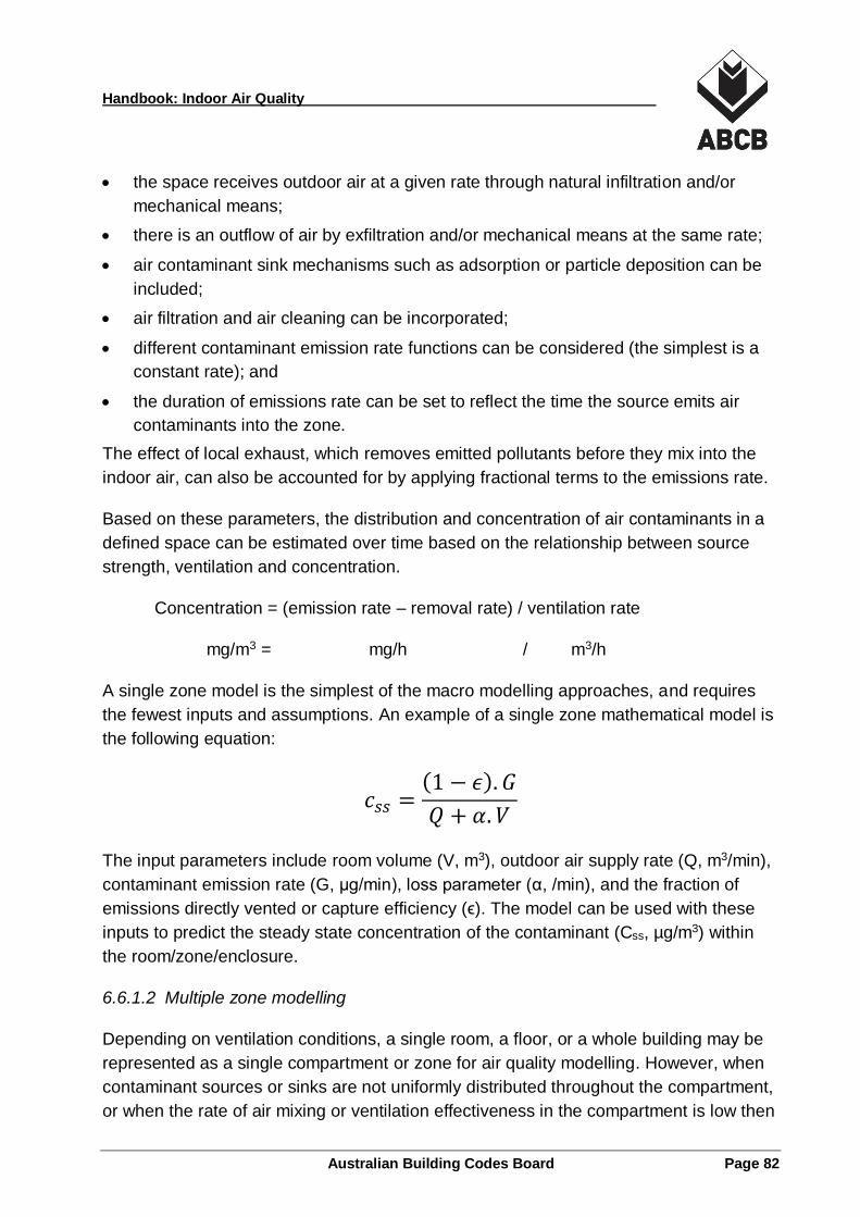
Handbook: Indoor Air Quality
Australian Building Codes Board Page 82
the space receives outdoor air at a given rate through natural infiltration and/or
mechanical means;
there is an outflow of air by exfiltration and/or mechanical means at the same rate;
air contaminant sink mechanisms such as adsorption or particle deposition can be
included;
air filtration and air cleaning can be incorporated;
different contaminant emission rate functions can be considered (the simplest is a
constant rate); and
the duration of emissions rate can be set to reflect the time the source emits air
contaminants into the zone.
The effect of local exhaust, which removes emitted pollutants before they mix into the
indoor air, can also be accounted for by applying fractional terms to the emissions rate.
Based on these parameters, the distribution and concentration of air contaminants in a
defined space can be estimated over time based on the relationship between source
strength, ventilation and concentration.
Concentration = (emission rate – removal rate) / ventilation rate
mg/m3 = mg/h / m3/h
A single zone model is the simplest of the macro modelling approaches, and requires
the fewest inputs and assumptions. An example of a single zone mathematical model is
the following equation:
𝑐𝑠𝑠 =(1 − 𝜖). 𝐺
𝑄 + 𝛼. 𝑉
The input parameters include room volume (V, m3), outdoor air supply rate (Q, m3/min),
contaminant emission rate (G, µg/min), loss parameter (α, /min), and the fraction of
emissions directly vented or capture efficiency (ϵ). The model can be used with these
inputs to predict the steady state concentration of the contaminant (Css, µg/m3) within
the room/zone/enclosure.
6.6.1.2 Multiple zone modelling
Depending on ventilation conditions, a single room, a floor, or a whole building may be
represented as a single compartment or zone for air quality modelling. However, when
contaminant sources or sinks are not uniformly distributed throughout the compartment,
or when the rate of air mixing or ventilation effectiveness in the compartment is low then
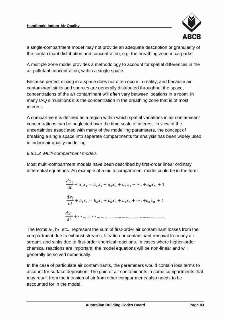
Handbook: Indoor Air Quality
Australian Building Codes Board Page 83
a single-compartment model may not provide an adequate description or granularity of
the contaminant distribution and concentration, e.g. the breathing zone in carparks.
A multiple zone model provides a methodology to account for spatial differences in the
air pollutant concentration, within a single space.
Because perfect mixing in a space does not often occur in reality, and because air
contaminant sinks and sources are generally distributed throughout the space,
concentrations of the air contaminant will often vary between locations in a room. In
many IAQ simulations it is the concentration in the breathing zone that is of most
interest.
A compartment is defined as a region within which spatial variations in air contaminant
concentrations can be neglected over the time scale of interest. In view of the
uncertainties associated with many of the modelling parameters, the concept of
breaking a single space into separate compartments for analysis has been widely used
in indoor air quality modelling.
6.6.1.3 Multi-compartment models
Most multi-compartment models have been described by first-order linear ordinary
differential equations. An example of a multi-compartment model could be in the form:
𝑑𝑥1
ⅆ𝑡+ 𝑎1𝑥1 = 𝑎2𝑥2 + 𝑎3𝑥3 + 𝑎4𝑥4 + ⋯ . +𝑎𝑛𝑥𝑛 + 1
𝑑𝑥2
ⅆ𝑡+ 𝑏1𝑥1 = 𝑏2𝑥2 + 𝑏3𝑥3 + 𝑏4𝑥4 + ⋯ . +𝑏𝑛𝑥𝑛 + 1
𝑑𝑥n
ⅆ𝑡+ ⋯ … = ⋯ … … … … … … … … … … … … … … … … ..
The terms a1, b1, etc., represent the sum of first-order air contaminant losses from the
compartment due to exhaust streams, filtration or contaminant removal from any air
stream, and sinks due to first-order chemical reactions. In cases where higher-order
chemical reactions are important, the model equations will be non-linear and will
generally be solved numerically.
In the case of particulate air contaminants, the parameters would contain loss terms to
account for surface deposition. The gain of air contaminants in some compartments that
may result from the intrusion of air from other compartments also needs to be
accounted for in the model.
Handbook: Indoor Air Quality
Australian Building Codes Board Page 84
6.6.2 Boundaries in a Model
The concepts of general flow and thermal boundary conditions are essential in
predicting air flow patterns and air quality in IAQ simulations. For any IAQ modelling
approach the boundary conditions need to be established. These include:
The physical boundaries of the space including, walls, floors, ceiling, roofs, air
barriers and openings and any associated radiative, convective and conductive heat
transfers;
Surfaces and surface coatings should also be considered, i.e. black walls and
aluminium walls;
The space geometry including the volumes, ceiling height and occupied zones;
Infiltration and exfiltration occurring at the boundaries of the simulation;
Outdoor air intake and room air exhaust airflows; and
The pressure relationships with adjacent spaces and the outdoors.
Boundary conditions should be realistic and accurately represented. Small changes to
boundary conditions may significantly affect the patterns of air flow and air contaminant
distribution.
6.6.3 Contaminant Sources and Sinks
Indoor air contaminants may be of outdoor or indoor origin.
Outdoor pollutants may enter a building through infiltration or ventilation air. Pollutants
of indoor origin may arise from point or diffuse sources. Regardless of their source, air
pollutants will typically be transported and dispersed in three dimensions, throughout
the space.
Some pollutants may be removed by air cleaning devices (through which outdoor air,
supply air or recirculated air flows), by exfiltration or exhaust ventilation to the outdoors,
or by chemical change. In the case of particles, surface generation characteristics and
removal through particle settlement rates are also important.
A useful categorisation of sources for air contaminants is:
point sources;
line sources; and
area sources.
Handbook: Indoor Air Quality
Australian Building Codes Board Page 85
The IAQ simulation should include source and sink models that detail the air
contaminant sources and their generation rates; as well as the air contaminant sinks
and their sink rates.
Source models can include both empirical models and mass transfer-based models.
empirical source models involve fitting measured concentrations and profiled
emissions with an appropriate equation, such as a power-law relationship.
mass transfer-based models involve solving fundamental equations governing the
emission process, for example from dry and wet building materials to the air.
Occupants are usually treated as sources of both air contaminants (e.g. carbon dioxide)
and heat. The occupant is often assumed not to move during the simulation.
Understanding the emission characteristics of different indoor sources over time is a
critical element of IAQ modelling.
Contaminant sinks are absorptive materials, typically dry and soft material like textiles,
carpeting, furnishings, acoustical ceiling tiles and gypsum board, that readily absorb the
VOC’s emitted by source materials. The interaction of indoor air contaminants with
indoor materials is known but poorly understood. Sink materials may re-release
absorbed air contaminants over a prolonged period of time and themselves become
sources.
Other sinks include the action of air cleaning devices and potentially the biological
activity of living plants.
6.6.4 Building Classifications
In some cases, the classification of the building will help to determine the different types
of air contaminant that may be expected during typical conditions of use. For instance,
for Class 7a carparks the only contaminant that is required to be verified is CO as this is
the dominant contaminant for these buildings. Building classifications can help
ventilation system designers identify potential air contaminants from:
the expected type of building occupant;
the activities typically undertaken in the building type; and
the types of materials typically used and stored in particular buildings.
Handbook: Indoor Air Quality
Australian Building Codes Board Page 86
6.6.5 Ventilation and Infiltration
For mechanically ventilated buildings it is the ventilation parameters of the building
HVAC system (i.e. flow rates, temperature, velocity, and throw) that are input into the
model.
For naturally ventilated buildings, the ventilation parameters are largely due to pressure
and temperature gradients, and these depend on the building shape and size, the
location and orientation of openings, the configuration of surrounding buildings and
topography, and the local meteorological parameters including the wind speed and
direction, the indoor and outdoor temperatures and the relative humidity.
6.6.6 Local and General Exhaust
Local and general exhaust streams are typically modelled using a fractional term to
simulate their effectiveness at removing the targeted air contaminant.
6.6.7 Air Cleaning Devices
Air cleaning devices are generally modelled based on their efficiency, their effectiveness
and the rate of air flow passing through them. Devices can be once through or
recirculating, full flow or side stream, and many devices need to include bypass factors.
Ongoing maintenance of air cleaning devices is essential for their continued
effectiveness. The actual rated efficiency at the applied air flow is generally available
from the manufacturer of the device.
6.6.8 Complexities of Simulation
The starting point in developing and using an indoor air contaminant model is usually a
statement of the mass balance concerning the pollutant of interest and the ventilation
system arrangements. Solutions to mass-balance equations invariably contain
parameters that must be evaluated independently.
Geometric parameters, such as definitions of volumes and surface areas, can be
measured directly, obtained from building plans or transferred electronically from
building information models (BIM). Accurate values of the ventilation parameters are
usually more difficult to determine.
The most difficult parameters to evaluate and define for the model are usually those
associated with the rate at which the air contaminant is being released or being
removed (i.e. the strengths of the contaminant sources and sinks). Simulating
Handbook: Indoor Air Quality
Australian Building Codes Board Page 87
ventilation air flows and indoor air contaminant concentrations within buildings has
many complexities including the following:
Multi-compartment models - Widely used compartmental IAQ models are broadly
classified into two categories single compartment and multi compartment IAQ
models. Analysing multiple individual compartments in a building all served by a
single ventilation system can result in a complex interlinking of, and interaction
between, multiple compartments with differing air contaminant profiles.
Models for sinks - For some buildings and systems sinks have to be incorporated
into the model to account for the action of adsorptive and absorptive surfaces and
materials, reactive gases, and any contaminants removed by air cleaners and the
like. Models for the adsorption of air contaminants and re-emission at a later time
are complex to develop and verify experimentally.
Models for sources - Models to simulate contaminant sources with different or
varying rates of contaminant releases, e.g. instant, exponential decay, constant,
need to be developed. Source models need to be developed for every source of
every air contaminant under investigation.
Modelling air mixing - when the air in the room is not well mixed, the dilution by
ventilation air is not necessarily uniform because the rates of dilution are not the
same in all parts of the room. A portion of the ventilation air stream often tends to
bypass some parts of the room. For instance, when both the inlet and exhaust ducts
are on the ceiling, the lower half of the room (and especially the corners) tend to be
bypassed and the air in these areas is diluted more slowly than predicted. A mixing
or ventilation effectiveness factor (a multiplier for the ventilation rate usually ranging
in value between 1.4 and 0.6) can be used to account for mixing rates that are lower
than would exist if the room air were continually well mixed (see 4.3.6).
Simulating laminar and turbulent flows - Most applications of CFD for room air
flow and heat transfer simulation have employed the K-epsilon (k-ε) turbulence
model which was originally developed for high-Reynolds number (i.e. fully turbulent)
flows. More research and development work is needed, particularly in the areas of
more efficient computational schemes, irregular and adaptive grids, turbulence
modelling and wall functions.
There are some models available that employ the use of low Mach number
approximations and turbulence models for sub-grid scale (SGS). SGS modelling is
used to represent the effects of unresolved small-scale fluid motions (small eddies,
swirls, vortices) in the equations governing the large-scale motions that are resolved
in computer models computations. These methods have been compared with full-
scale experiments with acceptable accuracy.
Handbook: Indoor Air Quality
Australian Building Codes Board Page 88
Many of these complexities are simplified when powerful software-based analytical tools
and simulation platforms are used in the air contaminant analysis.
6.7 IAQ Modelling Software Tools and Platforms
Air contaminant concentrations within a space can be manually calculated from the
space air volume, dilution air flow rate, and the air contaminant generation and removal
rates within the space. As designers consider calculating the concentration of multiple
contaminants in multiple compartments over a protracted time span then manual
calculations become complex and time consuming. Computer modelling and simulation
tools and platforms can significantly reduce the time and complexity of the analysis.
6.7.1 Modelling Software
There are a number of software programs readily available to simplify the process,
including freeware and proprietary software.
In many computer software programs ventilation and airflow models (for describing
natural, mechanical, infiltration or exfiltration airflows) are combined with a separate set
of air contaminant models, detailing temporal and spatial variations of the indoor
sources and sinks, physio-chemical transformations, indoor activities and background
concentration of contaminants in outdoor air. These models are then combined to
predict the indoor pollutant concentrations in ventilated buildings.
These programs and tools can combine microscopic and macroscopic simulation
techniques for multiple air contaminants within single and multiple compartments or
zones to build a complete ventilation, air contaminant and IAQ model for the building in
operation.
Appendix C provides a non-exhaustive list of some of the software tools available to
designers intending to model air contaminant transport in buildings and air contaminant
concentrations in occupied zones.
6.7.2 Interpretation and Graphical Visualisation of Results
The results and outputs of the simulation are generally provided through a graphical
user interface (GUI) program. This interface typically provides a dynamic visualisation
and analysis of the air transport calculations and resulting air contaminant concentration
levels.
All models and resulting simulations should be the subject of sensitivity analysis and
independent peer review (see Appendix C).
Handbook: Indoor Air Quality
Australian Building Codes Board Page 89
6.7.3 Validating IAQ Models
Indoor air quality models can be validated in accordance with ASTM D 5157, a guideline
that provides quantitative and qualitative tools for evaluation of IAQ models (ASTM
2014). These tools include methods for assessing the overall model performance as
well as identifying specific areas of deficiency. Tools include statistical formulae for
assessing the general agreement between predicted and measured values as well as
values for various statistical indicators that can be used when judging model
performance.
6.8 Monitoring Air Contaminant Levels
6.8.1 Monitoring
A performance-based approach to the management of ventilation and IAQ may include
a proactive monitoring program to inspect, analyse and evaluate the performance of the
building ventilation system on a regular basis.
Measurements are used to verify the operational performance of the system and the
results of these measurements are monitored and recorded to provide assurance that
the system is operating as designed. Measuring performance is also important for
system commissioning, system diagnostic analysis, design evaluation and ongoing
research and development.
The key to any monitoring system is to establish a baseline datum from which to
compare ongoing operation and performance. Baseline data is generally based on the
commissioning data which is itself derived from the system design and installation
documentation.
Monitoring instruments can include advanced useful features such as an internal data
logger and alarm relay outputs which inform when exceedances are reached.
6.8.2 Personal Monitors
Miniaturised air samplers are available that collect gaseous and particulate samples
from the immediate vicinity of people, even as they conduct their normal activities. They
all use sensitive chemical or physical analytic methods.
These sometimes wearable devices can be battery-powered non-passive samplers or
be diffusion- and permeation-controlled passive samplers. Passive devices are smaller
and lighter and generally only applicable for gas or vapour sampling.
Handbook: Indoor Air Quality
Australian Building Codes Board Page 90
Alternatively, sensors can be fixed wall or desk mounted devices monitoring a range of
IAQ/IEQ parameters and providing data feedback to central control and visualisation
systems, generally wirelessly.
6.8.3 Remote Monitors
Sampling and monitoring equipment can be placed in remote locations outside the
space being evaluated and draw air-sample streams to them.
6.8.4 Monitoring Ventilation Rates
Ventilation systems for buildings can vary considerably. Residential and small
commercial buildings are often naturally ventilated. Naturally ventilated spaces are
primarily ventilated by the controlled opening of windows and doors and the
uncontrolled infiltration of outdoor air and exfiltration of indoor air through cracks in the
building envelope (i.e. gaps around doors and windows, wall and floor joints, etc.).
Measurement of the natural ventilation and infiltration/exfiltration rates, and the
meteorologic factors that affect them (outdoor temperature, relative humidity, wind
speed, and wind direction), can be an integral part of fixed-location field monitoring.
Larger commercial buildings are often ventilated by mechanical systems. Mechanical
ventilation systems vary considerably in design and complexity. The methods chosen to
measure ventilation rates should be suitable for the systems under consideration. The
methods commonly used to determine the ventilation rate for mechanical systems
include:
pressure-measuring devices (such as inclined manometers and U-tubes);
velocity meters (such as pitot tubes, hot-wire flowmeters, heated-thermistor
flowmeters and heated-thermocouple flowmeters);
mechanical gas-flow indicators (such as rotating and deflecting-vane
anemometers);
tracer-gas techniques; and
heat-balance techniques.
6.8.5 NABERS IE Sampling and Measurement Protocols
The NABERS Indoor Environment for offices rating is calculated by comparing the
performance of the Indoor Environmental Quality (IEQ) of a building or tenancy (or both)
against other office buildings using benchmarks of performance. The IEQ of a building
Handbook: Indoor Air Quality
Australian Building Codes Board Page 91
is assessed against up to five different parameters one of which is Indoor Air Quality
(OEH 2015).
The NABERS IE assessment of indoor air quality utilises a range of quantitative
measurements taken on-site. These include measurements to quantify ventilation
effectiveness (measuring CO2), particulate matter measuring PM10, formaldehyde
(handheld or laboratory analysis), total volatile organic compounds (handheld or
laboratory analysis) and carbon monoxide (measured at outdoor air intake).
The protocols and instruments used and their specification could potentially be used to
develop an air sampling and monitoring methodology to prove the IAQ Verification
Method.
6.9 Testing Air Contaminant Concentration Levels
6.9.1 Measurement options
There are two basic methods used to measure airborne contaminants:
Air sampling over time – where materials are collected (typically on a filter or other
medium) and subsequently analysed in an environmental laboratory located away
from the sampling location; and
Measurements using real-time instruments – where measurements are made and
results obtained on-site. Photometers, optical particle counters and condensation
particle counters can be used for real-time measurements. The specific instrument
of choice depends on the application and the desired results.
6.9.2 Sampling Options
Sampling techniques fall into the following three broad categories:
Continuous sampling - real-time instantaneous sampling results allowing
observation of fluctuations in concentration over specified periods.
Integrated sampling - an average sampling result over a specified period providing a
mean concentration of the air contaminant.
Spot sampling - a single sample taken at specified intervals; suitable when
knowledge of air contaminant concentration variation over short periods is not
important.
Spot sampling typically consists of admitting an air sample into a previously evacuated
vessel, drawing a sample into a deflated bag for later analysis, or drawing a sample
through a sample collector to extract (and quantify) a contaminant from the air.
Handbook: Indoor Air Quality
Australian Building Codes Board Page 92
ISO 16000-1 is intended to aid the planning of indoor air contaminant monitoring. The
sampling strategy for indoor air monitoring, should clarify for what purposes, when,
where, how often and over what periods of time monitoring is to be performed. These
should be consistent with the concentration limits and exposures listed in the IAQ
Verification Method. ISO 16000-1 deals with these factors and offers suggestions on
how to develop a suitable sampling strategy.
6.9.3 Measuring Contaminant Levels
Measurements should be taken using hand-held equipment or an alternative method,
using the laboratory analytical methods as outlined in Appendix B, can be used.
Hand held instruments such as real-time organic gas (CO, CO2, NO2) infrared analysers
with output logged over time are generally suitable measuring devices.
The main instruments and methods of measuring particulate concentration are based
on either gravimetric, optical, or microbalance principles. The main methods of
measuring particulate size distribution are Scanning Mobility Particle Sizer and
Electrical Low Pressure Impactor.
Handbook: Indoor Air Quality
Australian Building Codes Board Page 93
References, Further Reading and Information Sources
A.1 References
The following Standards are referred to in the body of this Handbook:
AS 1324. 2 – 2003 Air filters for use in general ventilation and airconditioning Part 2:
Methods of test (Standards Australia 2003)
AS 1668.2 – 2012 The use of Ventilation and airconditioning in buildings Part 2:
Mechanical ventilation (Standards Australia 2012a)
AS 1668.4 – 2012 The use of Ventilation and airconditioning in buildings Part 4:
Natural ventilation of Buildings (Standards Australia 2012b)
ASHRAE 52.1 (Superseded) Gravimetric and Dust Spot Procedures for Testing Air
Cleaning Devices used in General Ventilation for Removing Particulate Matter
(ASHRAE 1992)
ASHRAE 52.2 Method of Testing General Ventilation Air-Cleaning Devices for
Removal Efficiency by Particle Size (ASHRAE 2007)
ASHRAE Standard 62.1: Ventilation for Acceptable Indoor Air Quality, American
Society of Heating, Refrigerating and Air-conditioning Engineers, Atlanta (ASHRAE
2016)
ASTM D5157 - 97(2014) Standard Guide for Statistical Evaluation of Indoor Air
Quality Models (ASTM 2014)
EN 779 Particulate air filters for general ventilation - Determination of filtration
performance (CEN 2012)
ISO 16000-1 Indoor air – Part 1: General aspects of sampling strategy (ISO 2004)
ISO FDIS 16890-1 Air filters for general ventilation – Part 1: Technical
specifications, requirements and classification system based upon particulate
matter efficiency (ePM) (Draft international Standard) (ISO 2016)
ISO 16814 Building environment design – Indoor air quality – Methods of
expressing the quality of indoor air for human occupancy (ISO 2008)
The following documents are referred to in the body of this Handbook:
AIRAH Application Manual DA15 Air filters (AIRAH 1998)
AIRAH Application Manual DA 26 Indoor Air Quality (AIRAH 2004)
AIRAH Application Manual DA 27 Building Commissioning (AIRAH 2011)
AIRAH Building Simulation Procurement Guidelines (AIRAH 2014)
Handbook: Indoor Air Quality
Australian Building Codes Board Page 94
ASHRAE Handbook of Fundamentals. 2013. American Society of Heating,
Refrigerating and Air-Conditioning Engineers, Atlanta USA (ASHRAE 2013)
ASHRAE Position Document on Indoor Air Quality, American Society of Heating,
Refrigerating and Air-Conditioning Engineers, Atlanta USA (ASHRAE 2011)
ASHRAE Position Document on Filtration and Air Cleaning (ASHRAE 2015)
ASHRAE Indoor Air Quality Guide 2009 – Best Practices for Design, Construction
and Commissioning, American Society of Heating, Refrigerating and Air-
Conditioning Engineers, Atlanta USA (ASHRAE 2009)
CIBSE Application Manual AM 11 2015 - Building Performance Modelling,
Chartered Institute of Building Services engineers, London (CIBSE 2015).
Health Effects Institute (2013). Understanding the Health Effects of Ambient
Ultrafine Particles. HEI: Boston, Massachusetts. (HEI 2013)
IARC Monographs Vol. 88, 2006, Formaldehyde, 2-Butoxyethamnol and 1-tert-
Butoxypropan-2-ol, International Agency for Research on Cancer, WHO: Lyon,
France. (IARC 2006)
IARC Monographs, Volume 105, 2012, Diesel and gasoline engine exhausts and
some nitroarenes, International Agency for Research on Cancer WHO: Lyon,
France. (IARC 2012).
GreenGuard Indoor Air Quality Standard for Office Equipment, GREENGUARD
Environmental Institute, Georgia USA (GreenGuard 2010)
NABERS Indoor Environment for offices, Rules for collecting and using data, 2015
NSW Office of Environment and Heritage, Sydney (OEH 2015)
National Environment Protection (Ambient Air Quality) Measure, 1998 as amended,
prepared by the Office of Legislative Drafting, Attorney-General’s Department,
Canberra (NEPM 1998)
NHMRC recommended Interim National Indoor Air Quality Goals 1996, National
Health and Medical Research Council, (NHMRC 1996 rescinded 2002)
NCC 2016 Volume One Building Code of Australia Class 2 to 9 Buildings, Australian
Building Codes Board, Canberra (ABCB 2016a)
NCC 2016 Volume Two Building Code of Australia Class 1 and 10 Buildings,
Australian Building Codes Board, Canberra (ABCB 2016b)
NEPC Report on the Implementation of the Ambient Air Quality NEPM, National
Environment Protection Council Annual Report 2004 – 2005 (NEPC 2005)
NEPC National Environment Protection (Ambient Air Quality) Measure Review
Report, National Environment Protection Council, 2011, (NEPC 2011a)
Handbook: Indoor Air Quality
Australian Building Codes Board Page 95
NSW State of the Environment Report 2015, NSW Environment Protection Authority
(EPA), Sydney (EPA 2015)
WHO guidelines for indoor air quality: selected pollutants, World Health
Organization (WHO 2010)
WHO Air quality guidelines. Global update 2005. Particulate matter, ozone, nitrogen
dioxide and sulphur dioxide. Copenhagen, WHO Regional Office for Europe, 2006.
(WHO 2006)
WHS Model Work Health and Safety Act, 2011, Safe Work Australia, Canberra
(SWA 2011a)
Workplace Exposure Standards for Airborne Contaminants, Safe Work Australia,
Canberra (SWA 2011b)
A.2 Further reading
A.2.1 Papers
Akoua et al 2002, Experimental and numerical studies on indoor air quality in a real
environment, C.S.T.B. - Centre Scientifique et Technique du Bâtiment, 2002, France
Chen et al 2015, EnergyPlus and CHAMPS-Multizone co-simulation for energy and
indoor air quality analysis, BUILD SIMUL (2015) 8: 371–380 DOI 10.1007/s12273-015-
0211-1
Clean Air Society of Australia and New Zealand 2002, Indoor Air Quality in Australia: A
Strategy for Action, FASTS Occasional paper No 5, Federation of Australian Scientific
and Technological Societies
Gungor K. 2015, Sources of errors for indoor air CFD simulations (Part 1), Ecolibrium
Magazine September 2015, AIRAH, Melbourne
Kelsey A. 2012, Effects of Local and General Exhaust Ventilation on Control of
Contaminants, Health and Safety Laboratory, Buxton UK, 2012
Luu I. and Brown G., 2015, Indoor Air Quality Assessment of Campus Spaces with
Carbon Dioxide (CO2) as a Measure of Adverse Health Effects
Panagopoulos et al 2011, A CFD Simulation Study of VOC and Formaldehyde Indoor
Air Pollution Dispersion in an Apartment as Part of an Indoor Pollution Management
Plan, Aerosol and Air Quality Research, 11: 758–762, 2011, Taiwan Association for
Aerosol Research
Handbook: Indoor Air Quality
Australian Building Codes Board Page 96
Rim et al 2012, Using Multi-zone Modeling of Particle Transport to Support Building
Design, International Committee on Sustainable Design, Engineering and Construction
Conference 2012
Spengler J.D. and Chen Q., 2000. Indoor air quality factors in designing a healthy
building, Annual Review of Energy and the Environment, 25, 567-600.
Shaw et al 2001, Material Emissions and Indoor Air Quality Modelling Project – An
Overview, Institute for Research in Construction, National Research Council Canada
2001
Wanget et al 2010, Using CFD capabilities of CONTAM 3.0 for simulating airflow and
contaminant transport in and around buildings, Accepted by HVAC&R Research. 2010
Yang et al 2014, CFD Simulations to Examine Natural Ventilation of a Work Area in a
Public Building, World Academy of Science, Engineering and Technology, International
Journal of Mechanical, Aerospace, Industrial, Mechatronic and Manufacturing
Engineering Vol:8, No:7, 2014
Yeramilli et al 2010, Measurement of Chemical Emissions from Building Products,
Volume 1 – 2010, The Australian Building Services Journal
A.2.2 Brochures and guides
Carpet Institute of Australia Limited “Carpet It Just Feels Better” Campaign brochure,
Consumer Health information - Indoor Air Quality, Carpet Institute of Australia Limited,
Melbourne
CRC for Construction Innovation, Brochure on the “Indoor Air Quality Estimator” 2008,
Cooperative Research Centre for Construction Innovation, Brisbane QLD (CRC 2008)
Design and Operational Strategies for High IAQ in Low Energy Buildings, International
Energy Agency (IEA) Energy Buildings and Community program, Executive Committee
Support Services Unit, AECOM Ltd 2015
Interior Design and Global Impacts - 2. Indoor Air Quality, American Society of Interior
Designers 2006 Washington, USA
National Association of Testing Authorities, ISO/IEC 17025 Standard Application
Document for accreditation of testing and calibration facilities, 2015 (NATA 2015)
NEPC Methodology for setting air quality standards in Australia Part A 2011, National
Environment Protection Council
Handbook: Indoor Air Quality
Australian Building Codes Board Page 97
U.S. Environmental Protection Agency (EPA), Indoor airPLUS Construction
Specifications V1 (Rev. 03) 2015
A.3 Additional Information Sources
ABCB http://www.abcb.gov.au/
National Construction Code and related products including Handbooks
AIRAH http://www.airah.org.au
Australian HVAC&R Industry application manuals and best practice guides
ASHRAE www.ashrae.org
American (USA) and regional standards and guides
CIBSE http://www.cibse.org/knowledge
Building services application manuals and guides
ISO http://www.iso.org/iso/home/standards.htm
International standards
Standards Australia http://infostore.saiglobal.com/store/default.aspx
Australian Standards and related products, regional and international standards
Handbook: Indoor Air Quality
Australian Building Codes Board Page 98
Data Sources for low-emission materials
B.1 Introduction
This Appendix provides a list of documents, websites and organisations which may be
useful sources of additional information on the following topics:
low-emission materials and products data bases;
sources of air contaminant emission data;
a list of online resources for low-emission materials and products; and
test methods for quantifying air contaminant emissions.
None of these lists are intended to be exhaustive and all are provided for information
only.
B.2 Evaluating and Selecting Low-emission Products
Off-gassing of contaminants from materials and products can be minimised by selecting
materials that contain smaller amounts of solvents or require less material for
application. These low-emission materials, practices or products are well suited for
projects targeting indoor air contaminant control.
Traditionally building materials are evaluated and selected based on performance,
aesthetics, and cost. When projects focus on air contaminant control, materials
selection parameters have to be expanded to include an evaluation of their air
contaminant emissions profile and potential effect on IAQ. Low-emission materials are
products that produce a lesser or reduced amount of air contaminants when compared
to competing products that serve the same purpose.
The growing popularity of green buildings and green building programs, such as the
Green Building Council of Australia’s Green Star rating system in Australia, has
expanded the demand and availability for low-emission building materials and products
in Australia and world-wide. For building designers and ventilation engineers these low-
emission materials provide greater opportunities to improve the air quality of building
projects.
Assessing the emissions of materials is a complex process, which can be further
confounded by varying and sometimes contradicting claims from product
manufacturers. However, there are product resources and tools available to help
designers make appropriate, informed materials evaluations and selections.
Handbook: Indoor Air Quality
Australian Building Codes Board Page 99
B.2.1 Emissions from Materials
Certain types of building materials and internal finishes are very prone to emitting
volatile organic compounds (VOCs) and other air contaminants. Manufacturers are
starting to communicate more about the presence of VOCs in products like paints,
adhesives, carpets and composite wood products.
Low-emission products promote good indoor air quality, typically through reduced
emissions of VOCs or formaldehyde. Examples of building materials that can come in
low VOC-emission formats include, solvents, paints, adhesives, carpeting, and
particleboard. Low-emission products should also be fit-for-purpose, durable, and have
low maintenance requirements. They should not contain any highly toxic compounds or
ozone depleting substances
The characteristics of low-emission products can vary significantly depending on the
material type. The evaluation of low-emission products requires a working knowledge
of:
the health and environmental impact issues associated with different air
contaminant emissions from different material types;
government, industry, and third-party standards for low-emission green products;
and
available low-emission products in the marketplace, including their performance
characteristics, appearance, and costs.
Information on the air contaminant emissions of materials and products is available from
a range of sources including:
Safety Data Sheets;
Third Party Certification Schemes;
Green Product Standards; and
Green Product Directories.
B.2.2 Safety Data Sheet (SDS)
WHS regulations require manufacturers and suppliers of products containing hazardous
chemicals to provide a document called a Safety Data Sheet or SDS (see 4.3.1) also
called Material Safety Data Sheet or MSDS.
Handbook: Indoor Air Quality
Australian Building Codes Board Page 100
SDSs contain information regarding potentially significant levels of airborne
contaminants, storage and handling precautions, health effects, odour description,
volatility, expected products of combustion, reactivity, and procedures for spill clean-up.
B.2.3 Third-Party Certification
Users should be wary of environmental claims (both positive and negative) that have
not been substantiated by independent sources
Third-party certification is the certification of a specific product or process that is
performed by an organisation independent from manufacturers or suppliers of the
product or process. Certification is often used to substantiate the environmental
attributes of a specific product, such as the VOC emissions.
B.2.4 Green Product Standards
To consistently assure the environmental performance (including air contaminant
emissions) of certain material types, several public agencies and private organizations
have developed green product standards. These standards define specific criteria for
various material types and many include the assessment and rating of the type and
level of air contaminants that are emitted from a product. In some cases, a trademarked
"green" label or tag can be used for complying products.
Green product standards can range from government regulations and guidelines to
industry guidelines (e.g. the Carpet and Rug Institute's Green Label program for
carpets), to third party certification standards (e.g. Green Seal standards for paints).
B.2.5 Green Product Directories
Typically hosted on a website, information is used to profile individual products from
specific manufacturers. Green Material Directories provide listings of available products
with the environmental attributes claimed by the manufacturers.
Examples include: GreenSpec™—The Environmental Building News Product Directory
B.3 Online Resources
There are a range of organisations that have developed assessment, testing and
certification systems for low emission materials, often as part of a broader
environmental or sustainability assessment. The following websites provide a range of
resources to enable the selection of low-emission materials.
Handbook: Indoor Air Quality
Australian Building Codes Board Page 101
BEES Online implements a powerful technique for selecting cost-effective,
environmentally-preferable building products, developed by the National Institute of
Standards and Technology (NIST) Engineering Laboratory. http://ws680.nist.gov/Bees
The Cradle to Cradle Products Innovation Institute, administers the publicly available
Cradle to Cradle Certified™ Product Standard which provides designers and
manufacturers with criteria and requirements for continually improving what products
are made of and how they are made. The mark provides consumers, regulators,
employees, and industry peers with a clear, visible, and tangible validation of a
manufacturer’s ongoing commitment to sustainability. There are courses for architects,
designers and students to help shift mindsets and strengthen professional credibility
and distinction. http://www.c2ccertified.org/about
The Collaborative for High Performing Schools (CHPS) offers a searchable high
performance building product database, in partnership with the U.S. Environmental
Protection Agency and Californian Department of Resources Recycling and Recovery.
The database includes the CHPS low-emitting materials list, other environmental
attributes, and life cycle and multiple attribute claims.
http://www.chps.net/dev/Drupal/self-certified-low-emitting-products
The Declare Database developed by the International Living Future Institute lists
building products whose ingredients have been fully disclosed and vetted against the
organisation’s Red List of the 22 “worst-in-class toxic chemicals pervasive in the
environment”. http://declareproducts.com/product-database
Ecospecifier Global provides a database of certified and verified Sustainable Products.
It provides a global source of life-cycle assessed product information, including building
and consumer product and air contaminant emission levels, which links independent
information with a powerful search interface. http://www.ecospecifier.com.au/
The GreenGuard Certification scheme recognizes building materials, finishes, interior
furnishings, furniture cleaning products, and electronic equipment with low chemical and
particle emissions. Its database of more than 27,000 certified products has been
integrated into Underwriters Laboratories Sustainable Product Guide.
http://productguide.ulenvironment.com/QuickSearch.aspx
Green Label Plus is an independent testing program that identifies carpet, adhesives,
and cushions with very low emissions of VOCs to help improve indoor air quality. It is an
outgrowth of, and enhancement to the Carpet and Rug Institute Green Label Testing
program. http://www.carpet-rug.org
Handbook: Indoor Air Quality
Australian Building Codes Board Page 102
Green Seal offers third-party certification based on leadership sustainability standards
that help protect the natural world and human health. The Green Seal standards
consider the total environmental impact of a product and reduce that impact while
maintaining the same performance and quality you would expect.
http://www.greenseal.org/AboutGreenSeal.aspx
Paint products bearing the Green Wise label have been tested and certified by
Coatings Research Group Incorporated (CRGI) to meet environmentally determined
performance standards established by CRGI’s ISO-accredited facility for specific
product types and to meet or exceed specified VOC limits. http://greenwisepaint.com/
Indoor airPLUS is a voluntary partnership and labelling program that helps new home
builders improve the quality of indoor air by requiring construction practices and product
specifications that minimize exposure to airborne pollutants and contaminants.
https://www.epa.gov/indoorairplus
The Pharos Project evaluates building products and components, profiles chemicals
and materials for health and environmental hazards and rates product certifications and
standards. https://www.pharosproject.net/
The Pharos website contains a range of resources:
The Pharos Building Product Library (BPL) combines manufacturer transparency
and independent research to provide in-depth health and environmental information
about a wide range of building products.
The Pharos Chemical and Material Library (CML) is an online catalogue of
chemicals, polymers, metals, and other substances. It identifies key health and
environmental information, restricted substance lists, and also characterizes the
process chemistry used to produce substances.
The Pharos Certifications and Standards Library provides information on
certifications and standards used to measure the environmental and health impacts
of building materials, including VOC content and emissions.
The CompAIR volatile ingredients calculator helps users identify building products
that release less chemicals into the air. Since some VOCs are hazardous, selecting
products with lower or no Volatile Ingredients can help avoid damaging worker and
occupant health. https://www.pharosproject.net/volatiles/
The Quartz Project is an open data initiative that promotes the transparency of building
products. The goal is to drive market transformation towards less toxic, lower-impact
materials for better buildings and healthier communities. http://www.quartzproject.org/
Handbook: Indoor Air Quality
Australian Building Codes Board Page 103
B.4 Making Material Selections
Given the many tools and resources available for evaluating and identifying low-
emission materials, it is useful to develop an organised process for making product
selections. Selecting low-emission materials requires research, critical evaluation, and
common sense. Specifiers are advised to collect the following information when
preparing to evaluate low-emission materials:
Critical performance criteria required of the material to be selected.
Appropriate product emission information, including the test method used and any
certification.
Material Safety Data Sheets (MSDS) for the products.
Maintenance expectations for the material or system.
Building products that may contain VOCs include carpets, paints and other finish
coatings, sealants, adhesives, and products that use adhesives extensively, such as
furniture and other composite wood products.
B.5 Specification Guidelines
Once a low-emission material has been evaluated and selected for a project, it is
important to include clear and binding specification language in the construction
documents.
B.6 Test methods for quantifying air contaminant emissions
B.6.1 Test Methods for Office Equipment
For office equipment the air contaminants tested can include NCC nominated indoor
pollutants TVOC, Ozone and Particulate. Compliance is demonstrated by the provision
of test certificates for equipment. Certificates should be issued by NATA/ISO 17025
accredited laboratories.
ISO/IEC 28360:2015 Information technology -- Office equipment -- Determination of
chemical emission rates from electronic equipment (Standard ECMA-328)
RAL UZ 171:2012 Basic Criteria For Award Of The Environmental Label - Office
Equipment With Printing Functions (Printers, Copiers, Multifunction Devices)
GGPS.003 Greenguard Indoor Air Quality (IAQ) Standard for Office Equipment
(Hardcopy devices) 2010
Handbook: Indoor Air Quality
Australian Building Codes Board Page 104
B.6.2 Test Methods for Materials Emissions
Emissions rating for construction products require chemical emissions from
representative samples to be tested under simulated real-world conditions. Tests are
performed by accredited laboratory facilities to accepted published standards.
Certificates should be issued by NATA ISO 17025 accredited laboratories. The air
contaminants tested can include the NCC nominated indoor pollutants; formaldehyde
and TVOCs.
VOCs are emitted from products throughout their lifetime. Rate of emission testing
involves testing the product in a specified chamber, and measuring the emissions
released during a specified period of time.
Standardised test methods are available for textiles and floor coverings, paints and
varnishes, and engineered wood products. Engineered wood products include
particleboard, plywood, medium density fibreboard, laminated veneer lumber, high-
pressure laminate, compact laminate and decorative overlaid wood panels. The
following is a list of some of the common test methods used:
AS/NZS 2098.11:2005 Methods of test for veneer and plywood Method 11:
Determination of formaldehyde emissions for plywood
AS/NZS 4266.16:2004 Reconstituted wood-based panels - Methods of test -
Formaldehyde emission - Desiccator method
AS/NZS 4357.4:2005 Structural laminated veneer lumber - Determination of
formaldehyde emissions
ASTM D3960 Standard Practice for Determining Volatile Organic Compound
(VOC)Content of Paints and Related Coatings
ASTM D5116: Standard guide for small-scale environmental chamber
determinations of organic emissions from indoor materials/products
ASTM D5197 Standard Test Method for Determination of Formaldehyde and Other
Carbonyl Compounds in Air (Active Sampler Methodology)
ASTM D6007 Standard Test Method for Determining Formaldehyde Concentrations
in Air from Wood Products Using a Small-Scale Chamber
ASTM D6196: Standard practice for selection of sorbents, sampling and thermal
desorption analysis procedures for volatile organic compounds in air.
ASTM D6803 Standard Practice for Testing and Sampling of Volatile Organic
Compounds (Including Carbonyl Compounds) Emitted from Paint Using Small
Environmental Chambers
Handbook: Indoor Air Quality
Australian Building Codes Board Page 105
ASTM D7339 Standard Test Method for Determination of Volatile Organic
Compounds Emitted from Carpet using a Specific Sorbent Tube and Thermal
Desorption / Gas Chromatography
ASTM D7706: Standard practice for rapid screening of VOC emissions from
products using micro-scale chambers.
ASTM E1333 Standard Test Method for Determining Formaldehyde Concentrations
in Air and Emission Rates from Wood Products Using a Large Chamber
EN 717-1:2004 Wood-based panels. Determination of formaldehyde release.
Formaldehyde emission by the chamber method
EN 717-2:1995 Wood-based panels. Determination of formaldehyde release.
Formaldehyde release by the gas analysis method
ISO 10580: Resilient, textile and laminate floor coverings -- Test method for volatile
organic compound (VOC) emissions
ISO 11890-1: Paints and varnishes -- Determination of volatile organic compound
(VOC) content -- Part 1: Difference method
ISO 11890-2: Paints and varnishes -- Determination of volatile organic compound
(VOC) content -- Part 2: Gas-chromatographic method
ISO 16000-3: Indoor air – Part 3: Determination of formaldehyde and other carbonyl
compounds in indoor air and test chamber air – Active sampling method.
ISO 16000-6: Indoor air – Part 6: Determination of VOCs in indoor and test chamber
air by active sampling on Tenax TA sorbent, thermal desorption and gas
chromatography using MS/FID.
ISO 16000-9: Indoor air – Part 9: Determination of the emission of volatile organic
compounds from building products and furnishing – Emission test chamber method
ISO 16000-10: Indoor air – Part 10: Determination of the emission of volatile organic
compounds from building products and furnishing – Emission test cell method.
ISO 16000-11: Indoor air – Part 11: Determination of the emission of volatile organic
compounds from building products and furnishing – Sampling, storage of samples
and preparation of test specimens.
ISO 16000-25: Determination of the emission of semi-volatile organic compounds
by building products – Micro-chamber method.
ISO/IEC 17025 (General requirements for the competence of testing and calibration
laboratories)
ISO/IEC 17025 Standard Application Document for accreditation of testing and
calibration facilities
Handbook: Indoor Air Quality
Australian Building Codes Board Page 106
ISO 17895 Paints and varnishes -- Determination of the volatile organic compound
content of low-VOC emulsion paints (in-can VOC)
CEN/TS 16516:2013 Construction products - Assessment of release of dangerous
substances - Determination of emissions into indoor air
B.6.3 Test Methods for Outdoor Air Contaminants
The following test methods can be applied to outdoor air testing:
AS 3580.5.1-2011 Ambient Air – Determination of Oxides of Nitrogen –
Chemiluminescence Method
AS 3580.6.1-2011 Ambient Air – Determination of Ozone – Direct Reading
Instrument Method
AS 3580.7.1-2011 Ambient Air – Determination of Carbon Monoxide – Direct
Reading Instrument Method
AS 3580.9.8-2008 Determination of Suspended Particulate Matter – PM10
continuous direct mass method using a Tapered element oscillating microbalance
(TEOM)
AS/NZS 3580.9.12:2013 Determination of Suspended Particulate Matter - PM2.5
Beta Attenuation Monitors
AS/NZS 3580.9.10:2006. Determination of Suspended Particulate Matter – PM2.5
low volume sampler – Gravimetric method
Handbook: Indoor Air Quality
Australian Building Codes Board Page 107
IAQ Models and Simulation Software
C.1 Simulation software for air contaminant concentrations
Air contaminant concentrations in a ventilated space can be manually calculated from
the space air volume, the ventilation air flow rate, and the contaminant generation rates
within the space. Manual calculations can be laborious and complex and the calculation
process is simplified with the use of computer software or modelling platforms.
There are a number of software programs readily available to simplify the process. This
Appendix contains several non-exhaustive lists outlining some of the tools available to
the designer. None of these lists are intended to be exhaustive and all are provided for
information only.
C.1.1 CONTAM
CONTAM is a multizone indoor air quality and ventilation analysis computer program
provided by the National Institute of Standards and Technology (NIST). The computer
software is designed to help designers determine:
Airflows: Infiltration, exfiltration, and room-to-room airflows in building systems
driven by mechanical means, wind pressures acting on the exterior of the building,
and buoyancy effects induced by the indoor and outdoor air temperature difference.
Contaminant Concentrations: the dispersal of airborne contaminants transported by
these airflows; transformed by a variety of processes including chemical and radio-
chemical transformation, adsorption and desorption to building materials, filtration,
and deposition to building surfaces, etc.; and generated by a variety of source
mechanisms, and
Personal Exposure: the predictions of exposure of occupants to airborne
contaminants for eventual risk assessment.
CONTAM can be useful in a variety of applications. Its ability to calculate building
airflows is useful to assess the adequacy of ventilation rates in a building, to determine
the variation in ventilation rates over time and the distribution of ventilation air within a
building, and to estimate the impact of envelope air tightening efforts on infiltration rates.
The prediction of contaminant concentrations can be used to determine the indoor air
quality performance of a building before it is constructed and occupied, to investigate
the impacts of various design decisions related to ventilation system design and building
material selection, and to assess the indoor air quality performance of an existing
building. Predicted contaminant concentrations can also be used to estimate personal
Handbook: Indoor Air Quality
Australian Building Codes Board Page 108
exposure based on occupancy patterns in the building being studied. Exposure
estimates can be compared for different assumptions of ventilation rates and source
strengths.
CONTAM is distributed as free software by NIST. http://www.nist.gov
C.1.2 CONTAM Model/TRNSYS Simulation
In order to better address the interdependencies and the interactions between heat
transfer, inter-zone airflow and indoor contaminant transport the National Institute of
Standards and Technology (NIST) has developed an updated version of the multi-zone
airflow and contaminant transport modelling tool, CONTAM, along with a set of utilities
to enable coupling of the full CONTAM model with the TRNSYS simulation tool in a
more seamless manner and with additional capabilities that were previously not
available.
This new coupled simulation capability will enable users to apply the tool to couple
CONTAM with existing energy analysis software to address the interaction between
indoor air quality considerations and energy conservation measures in building design
and analysis.
C.1.3 CHAMPS-Multizone
CHAMPS-Multizone (CHAMPS-MZ) is a simulation program for whole building
combined heat, air, moisture, and pollutant simulation.
It is a software tool for free non-commercial use developed through a joint effort
between Syracuse University (USA.) and University of Technology Dresden (Germany).
Its user community includes research institutes and consulting companies. The program
is used for analysis and prediction of:
Combined building energy, moisture, and pollutants simulation in building zonal
scale;
Impact of outdoor climate and pollution on indoor environment and its energy
consumption penalty;
Building design parameters studies to assist and optimize building design process
through building performance-based simulation.
The CHAMPS-MZ software has a solar radiation model, building envelope model,
airflow network model, and zone and HVAC model to predict the combined energy and
IAQ performances of a whole building. A GUI is included for users to input the design or
control parameters. http://champs.syr.edu/software/champs_mz/champs_mz.html
Handbook: Indoor Air Quality
Australian Building Codes Board Page 109
C.1.4 IA-QUEST
IA-QUEST 1.1 is both a database of material emission test results and an indoor air
quality simulation program, provided by the National Research Council of Canada.
The database component provides information on the emission of specified VOCs and
TVOC from common (Canadian) building materials. The simulation component
calculates the concentrations of contaminants that would occur in a room with known
ventilation rate and schedule due to emissions from materials contained within that
space. The calculation of concentrations assumes a simple single-zone perfect mixing
model. The emission characteristics of materials are obtained from the database
packaged within the program.
Users need to input the following information to estimate indoor air concentrations of air
contaminants arising from single or multiple building materials:
Volume of the space;
Ventilation rate and schedule;
For each material (selected from database):
o exposed/emitting surface area;
o entry and removal times to/from the space;
The period of the simulation.
IA-Quest is distributed as free software by NRC. http://www.nrc-cnrc.gc.ca
C.1.5 I-BEAM
The I-BEAM or Indoor Air Quality Building Education and Assessment Model, is a
guidance tool produced by the USA Environmental Protection Agency. It is primarily
designed for use by building professionals and others interested in indoor air quality in
commercial buildings. I-BEAM updates and expands EPA's Building Air Quality
guidance, and is designed to provide comprehensive guidance for managing IAQ in
commercial buildings.
I-BEAM consists of many individual modules which explain different aspects of IAQ
including:
Conducting an indoor air quality building audit;
Diagnosing and resolving IAQ related health problems;
Establishing an IAQ management and maintenance program to reduce IAQ risks;
Handbook: Indoor Air Quality
Australian Building Codes Board Page 110
Planning IAQ compatible energy projects;
Protecting occupants from exposures to construction/renovation contaminants;
Calculating the cost, revenue and productivity impacts of planned IAQ activities.
C.1.6 IAQ Estimator
The Indoor Air Quality Estimator is a prototype software tool developed by the CRC
for Construction Innovation and CSIRO for estimating indoor air quality in commercial
buildings. The IAQ-Estimator is an office design tool for selection of materials, office
equipment, and ventilation filtration to optimise indoor air quality and allow control of
indoor air pollutants.
http://www.construction-innovation.info/images/pdfs/Brochures/IAQ_email_version.pdf
C.1.7 IAQ Tools
IAQ Tools is a proprietary software program that solves problems concerning a wide
variety of airborne contaminants, ventilation design, filter design and selection, design
for contaminant source control, tracer gas calculations, and air quality unit conversions.
IAQ Tools has a variety of flexible calculation options that solve for ventilation rates,
contaminant concentrations, or contaminant generation rates (steady state model).
IAQ Tools performs calculations for more than 30 different contaminants, including a
wide variety of gases, airborne solid contaminants, bio-aerosols, and tracer gases.
http://www.elitesoft.com/web/hvacr/iaqtools.htm
C.1.8 TRNFlow
TRNSYS thermal multi-zone building models requires air flows between zones as input
values. In natural ventilation systems these depend on the wind pressures and the
inside and outside temperatures. To account for this situation TRNFLOW – AIRFLOW
SIMULATION IN BUILDINGS integrates the multi-zone air flow model COMIS into the
TRNSYS thermal multizone building model. TRNFlow includes calculation of the air
exchange taking into account window ventilation, infiltration/exfiltration, airflow between
rooms, mechanical outdoor and exhaust air, and multizone fluid simulation accounting
for wind pressures, temperature differences and mechanical ventilation forces. The data
for the air flow model is entered using the existing TRNBuild GUI.
http://sel.me.wisc.edu/trnsys/addons.html
Handbook: Indoor Air Quality
Australian Building Codes Board Page 111
C.1.9 DesignBuilder
DesignBuilder provides advanced modelling tools in an easy-to-use interface. This
enables the whole design team to use the same software to develop comfortable and
energy-efficient building designs from concept through to completion. In EnergyPlus the
HVAC and building 3D models are simulated simultaneously to ensure the dynamic
interaction between the building and systems is treated accurately.
http://www.designbuilder.co.uk/hvac
C.1.10 BIM Platforms and IAQ
As the complexity, capability and uptake of Building Information Modelling (BIM)
software platforms continues to expand it is likely that they will include ventilation and
IAQ models and simulation capabilities. This is a rapidly developing technical area.
The integration of building design and construction software, with geographic
information system (GIS), wireless sensors, building control systems, online real-time
data banks and cloud computing technologies offers innovative opportunities for indoor
air quality management and real-time monitoring.
C.2 CFD software for air contaminant concentrations
C.2.1 Class 7a Carpark Ventilation
While single-zone models may provide the carpark ventilation system designer with
general expectations and averages of how a system design may perform based on the
net transfer of air contaminants, these models may not always provide the high degree
of accuracy required for carpark ventilation system design. Microscopic models (i.e.
CFD software) provide an increased degree of accuracy at a scale that can provide the
designer with a high level of confidence of the expected performance of the ventilation
system design.
There is a wide range of open source and proprietary CFD software programs available
to assist in the analysis of ventilation and carbon monoxide transport and dilution within
carparks.
C.2.2 ANSYS Fluid Dynamics®
ANSYS fluid dynamics is a product suite for modelling fluid flow and other related
physical phenomena. It contains both general purpose CFD software, ANSYS CFX and
ANSYS FLUENT, and additional specialised products to address specific applications.
Handbook: Indoor Air Quality
Australian Building Codes Board Page 112
ANSYS CFD provides a tool to assess the levels of thermal comfort for building
occupants, by examining parameters such as the air temperature and radiant heat
loads, as well as a tool to ensure adequate air change effectiveness by solving and
assessing the mean age of air. FLUENT is a commercial CFD program developed by
Ansys Inc.
http://www.leapaust.com.au/ansys-fluids/
C.2.3 FloVENT®
FloVENT software predicts three-dimensional airflow, heat transfer, contamination
distribution and comfort indices in and around buildings, and is designed specifically for
the design and optimisation of heating, ventilating and air-conditioning (HVAC) systems.
FloVENT Version 10.1 is the latest version.
https://www.mentor.com/products/mechanical/flovent/
C.2.4 OpenFOAM®
OpenFOAM is a free, open source CFD software. OpenFOAM has an extensive range
of features to solve anything from complex fluid flows involving chemical reactions,
turbulence and heat transfer, to acoustics, solid mechanics and electromagnetics.
http://www.openfoam.com/
C.2.5 PHOENICS®
PHOENICS is a general-purpose software package that predicts quantitatively how
fluids (air, water, steam, oil, blood, etc.) flow in and around, the associated changes of
chemical and physical composition and the associated stresses in the immersed solids.
In architecture, PHOENICS is used to predict the airflow in and around buildings, to
improve the architectural design and thermal comfort.
http://www.cham.co.uk/
C.2.6 simFlow®
simFlow CFD Software is a numerical modeling tool that combines a graphical user
interface with the open-source OpenFOAM® libraries with functionality to handle
phenomena such as compressible and incompressible fluid flow, turbulent flows, heat
transfer, including conjugate heat transfer, multiphase flows, cavitation and chemical
reactions.
Handbook: Indoor Air Quality
Australian Building Codes Board Page 113
https://sim-flow.com/cfd-software/
C.2.7 STAR-CCM+®
STAR-CCM+ is a CFD program with an entire engineering process for solving problems
involving flow (of fluids or solids), heat transfer and stress. It can tackle problems
involving multi-physics and complex geometries to help automate simulation workflows
and perform iterative design studies with minimal user interaction.
http://www.cd-adapco.com/products/star-ccm%C2%AE
C.2.8 HyperWorks®
HyperWorks provides a full suite of CFD tools for both the expert and novice users, to
generate fast and accurate simulations of fluid flow and heat transfer systems from
detailed component analysis to full systems performance.
http://www.altairhyperworks.com/product/AcuSolve
C.3 Vehicle emission models for Class 7a Carpark Ventilation
There is a wide range of vehicle emission models available to assist in the
determination of air contaminant generation rates by different types and sizes of
vehicles. New vehicles in Australia must comply with Australian Design Rule 79/02 —
Emission Control for Light Vehicles (2005).
The following provides a brief summary of some of the models available.
C.3.1 ARTEMIS
ARTEMIS (Assessment and Reliability of Transport Emission Models and Inventory
Systems) - The European ARTEMIS project developed the Common Artemis Driving
Cycles (CADC) based on statistical analysis of a large database of European real world
driving patterns. Such driving cycles present a real advantage as they are derived from
a large database, using a methodology that was widely discussed and approved. The
ARTEMIS programme built upon the earlier recommendations arising from the fourth
framework project MEET.
C.3.2 CUEDC
CUEDC (Composite Urban Emissions Drive Cycles) - In Australia a Composite Urban
Emissions Drive Cycle (CUEDC) was developed for light duty petrol vehicles in 2005.
Handbook: Indoor Air Quality
Australian Building Codes Board Page 114
This followed the development of CUEDC cycles for diesel vehicles in 1998. The Petrol
CUEDC was developed to be representative of “real world” Australian urban driving.
C.3.3 COPERT 4
COPERT 4 (COmputer Programme to calculate Emissions from Road Transport) is a
software tool supported by the European Environment Agency and used world-wide to
calculate air pollutant and greenhouse gas emissions from road transport. COPERT 4
contains emission factors for more than 240 individual vehicle types. Emission control
technologies are included for the vehicle categories; additional user-defined
technologies can be included. Different methods are used to estimate emissions of the
various pollutants.
http://emisia.com/products/copert-4
C.3.4 HBEFA
The Handbook Emission Factors for Road Transport (HBEFA) provides emission
factors for all current vehicle categories (i.e. cars, light duty vehicles, heavy duty
vehicles, urban buses, coaches and motor cycles), each divided into different
categories, for a wide variety of traffic situations. Emission factors for all regulated and
the most important non-regulated pollutants as well as fuel consumption and CO2 are
included. The latest version is HBEFA 3.2 (published July 2014).
http://www.hbefa.net/e/index.html
C.3.5 MOVES
MOVES (Motor Vehicle Emission Simulator) – The USA EPA’s MOVES emission
modelling program estimates emissions for mobile sources at the national, county, and
project level for criteria air pollutants. MOVES 2014a is the latest version.
C.3.6 PHEM
PHEM is a vehicle simulation tool capable of simulating vehicle hot and cold emissions
for different driving cycles, gear shift strategies, vehicle loadings, road gradients, vehicle
characteristics (mass, size, air resistance, etc.). PHEM has been validated by emission
measurements both from light and heavy duty vehicles in the laboratories (chassis and
engine test bed) and on the road (with PEMS) and under different test conditions. If fed
with a detailed list of vehicle specifications PHEM is capable of modelling emission
levels on a large variety of conditions not covered by the available measurements.
Handbook: Indoor Air Quality
Australian Building Codes Board Page 115
C.3.7 VERSIT+
VERSIT+ is constituted by a suite of models, used to predict emission factors and
energy use factors that are representative for vehicle fleets in different countries.
Emission factors are differentiated for various vehicle types and traffic situations, and
take into account real-world driving conditions.
http://www.tno.nl/downloads/lowres_TNO_VERSIT.pdf
C.4 Inputs and Assumptions
Building simulation and ventilation or indoor air quality modelling typically uses a
computer to solve the relevant science-based mathematical equations, using
information and data about the specific design circumstances under analysis. The data
is typically selected from defaults within the programming, calculated by internal models
and algorithms or input by the simulator.
The main components of the simulation process are:
the person who describes the problem;
the scientific knowledge that is expressed mathematically;
the computer software (code) which embodies this knowledge and expresses the
stated problem in scientific terms;
the computer hardware which performs the calculations dictated by the software;
and
the person being who inspects and interprets the results of the simulation.
As with any calculation, model, analysis or simulation, the accuracy of the data that is
output from the analysis is entirely dependent on the accuracy of the data that is input.
Bad data in = Bad data out
All inputs and assumptions used in the analysis should be documented for future
reference. Some software can check the data input and alert to any potential (out of
range) errors before it provides calculations or analysis. Interpretation of results should
also be documented and a sensitivity analysis conducted.
Handbook: Indoor Air Quality
Australian Building Codes Board Page 116
C.5 Sensitivity Analysis
Sensitivity analysis is the investigation of the potential changes to, and errors in, the
input data and assumptions of any model and the impacts that those changes and
errors can have on the conclusions that can be drawn from the results of the simulation.
Sensitivity analysis is performed by carrying out multiple simulation runs while varying
specific building, ventilation and contaminant transport model parameters, to determine
the effect that those specific changes or actions will have on air contaminant
concentration levels.
The results of the analysis can highlight which air contaminant control parameters are
the most important and their effect on ventilation strategies in different applications and
conditions can be quantified.
Inputs such as climate conditions, building thermal performance, fabric infiltration,
occupation densities and uses, cooling and heating loads, configurations of openings
and ducts, and ventilation rates can all be varied to show the effect changes will have
on air contaminant concentration levels.
C.6 Procuring simulation services
The lack of regulation in the building simulation industry can make it difficult to engage a
quality consultant to complete a simulation task. Common problems clients face include
lack of understanding of the type of simulation required, the outcome needed and the
steps necessary to achieve that goal, poorly defined modelling scope creating difficulty
in comparing quotes and lack of confidence in the skill of the modeller and the quality of
the simulation.
The AIRAH Building Simulation Procurement Guidelines (AIRAH 2014) provides advice
for the client, developer, architect, engineer, building owner, facility manager, managing
agent, etc. intending to engage a consultant to complete a building simulation.
C.7 Competencies of the Simulator
The AIRAH Building Simulation Procurement Guidelines (AIRAH 2014) provides some
guidance on what to look for in a consultant simulator.
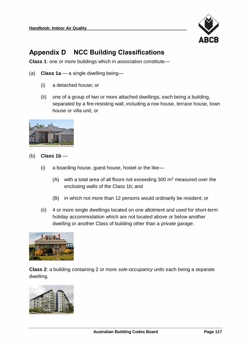
Handbook: Indoor Air Quality
Australian Building Codes Board Page 117
NCC Building Classifications
Class 1: one or more buildings which in association constitute—
(a) Class 1a — a single dwelling being—
(i) a detached house; or
(ii) one of a group of two or more attached dwellings, each being a building,
separated by a fire-resisting wall, including a row house, terrace house, town
house or villa unit; or
(b) Class 1b —
(i) a boarding house, guest house, hostel or the like—
(A) with a total area of all floors not exceeding 300 m2 measured over the
enclosing walls of the Class 1b; and
(B) in which not more than 12 persons would ordinarily be resident; or
(ii) 4 or more single dwellings located on one allotment and used for short-term
holiday accommodation which are not located above or below another
dwelling or another Class of building other than a private garage.
Class 2: a building containing 2 or more sole-occupancy units each being a separate
dwelling.
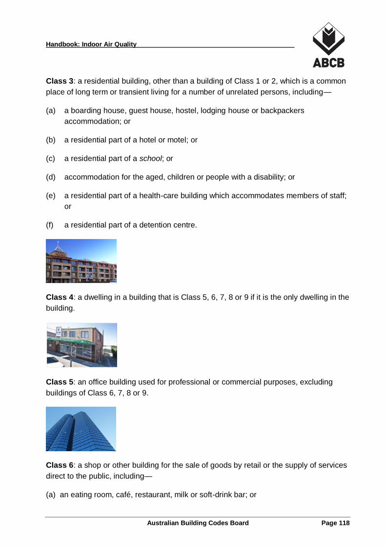
Handbook: Indoor Air Quality
Australian Building Codes Board Page 118
Class 3: a residential building, other than a building of Class 1 or 2, which is a common
place of long term or transient living for a number of unrelated persons, including—
(a) a boarding house, guest house, hostel, lodging house or backpackers
accommodation; or
(b) a residential part of a hotel or motel; or
(c) a residential part of a school; or
(d) accommodation for the aged, children or people with a disability; or
(e) a residential part of a health-care building which accommodates members of staff;
or
(f) a residential part of a detention centre.
Class 4: a dwelling in a building that is Class 5, 6, 7, 8 or 9 if it is the only dwelling in the
building.
Class 5: an office building used for professional or commercial purposes, excluding
buildings of Class 6, 7, 8 or 9.
Class 6: a shop or other building for the sale of goods by retail or the supply of services
direct to the public, including—
(a) an eating room, café, restaurant, milk or soft-drink bar; or
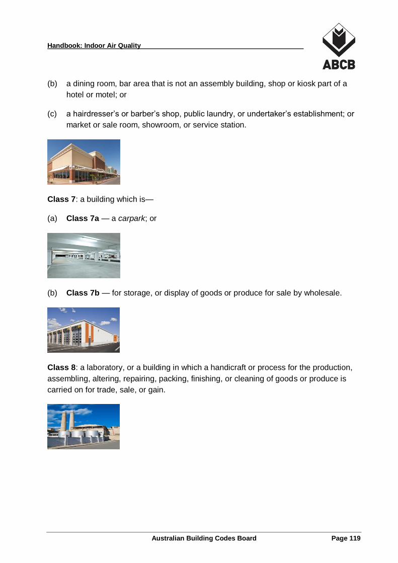
Handbook: Indoor Air Quality
Australian Building Codes Board Page 119
(b) a dining room, bar area that is not an assembly building, shop or kiosk part of a
hotel or motel; or
(c) a hairdresser’s or barber’s shop, public laundry, or undertaker’s establishment; or
market or sale room, showroom, or service station.
Class 7: a building which is—
(a) Class 7a — a carpark; or
(b) Class 7b — for storage, or display of goods or produce for sale by wholesale.
Class 8: a laboratory, or a building in which a handicraft or process for the production,
assembling, altering, repairing, packing, finishing, or cleaning of goods or produce is
carried on for trade, sale, or gain.
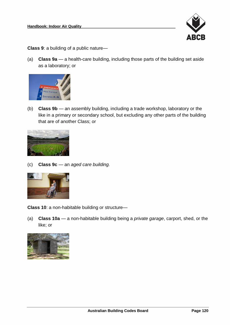
Handbook: Indoor Air Quality
Australian Building Codes Board Page 120
Class 9: a building of a public nature—
(a) Class 9a — a health-care building, including those parts of the building set aside
as a laboratory; or
(b) Class 9b — an assembly building, including a trade workshop, laboratory or the
like in a primary or secondary school, but excluding any other parts of the building
that are of another Class; or
(c) Class 9c — an aged care building.
Class 10: a non-habitable building or structure—
(a) Class 10a — a non-habitable building being a private garage, carport, shed, or the
like; or
Handbook: Indoor Air Quality
Australian Building Codes Board Page 121
(b) Class 10b — a structure being a fence, mast, antenna, retaining or free-standing
wall, swimming pool, or the like; or
(c) Class 10c — a private bushfire shelter.