Embed Size (px)
Citation preview

PFGW File No. 1307 University of Kentucky College of Agriculture McCracken County Cooperative Extension Office Paducah, Kentucky
ADDENDUM NO. 2 009002 - 1
SECTION 009002 – ADDENDUM NO. 2 DATE OF ISSUE: December 1, 2014
Office Facility McCracken County Cooperative Extension
2025 New Holt Road Paducah, Kentucky
This Document is an amendment of the original Specifications and/or Drawings and shall be part of and included in the Contract. Wherein this Addendum conflicts with the original Specifications and/or Drawings, this Addendum shall govern.
BIDDING REQUIREMENTS
ITEM NO. 1: SECTION 000110 - TABLE OF CONTENTS
a. Insert Section 232113 – Hydronic Piping, 10 pages.
ITEM NO. 2: SECTION 007314 – SUPPLEMENTAL CONDITIONS
b. Revise Paragraph 3.1 to increase Construction time to three hundred sixty (360) days.
TECHNICAL SPECIFICATIONS
ITEM NO. 3: SECTION 232113 – HYDRONIC PIPING.
Add the specification section in its entirety.
ITEM NO. 4: SECTION 074113.16 – STANDING-SEAM METAL ROOFING PANELS
Refer to Article 2.5 of Section 075419 – PVC Roofing for specification of board insulation panels. Installation to be similar to method outlined in Part 3 of Section 075419 in terms of thickness. Fastening of panels to comply with metal roofing panel manufacturer recommendations.
ITEM NO. 5: SECTION 232113.33 – GROUND LOOP HEAT PUMP PIPING.
a. Per Paragraph 1.4, A., the following Geothermal Contractors/Bidders have provided documentation identifying the requisite size, manpower, experience, and recognition of the relevant site geology to be considered as Approved Bidders for the project.
b. It is noted that the Engineer makes no guarantees expressed or implied as to each organization’s ability to either complete the work successfully or perform the work in the required timeline to meet the construction sequence.

PFGW File No. 1307 University of Kentucky College of Agriculture McCracken County Cooperative Extension Office Paducah, Kentucky
ADDENDUM NO. 2 009002 - 2
c. Each Contractor is advised to exercise due diligence in vetting each organization prior to consideration.
d. The successful Geothermal Contractor/Bidder will be required to submit all relevant Shop Drawing information as specified in Section 232113.33.1.3 and the required Performance Bond as specified in Section 232113.33.1.4.A.
• Durbin Enterprises
Dominique Durbin Beecher City, IL 6180487-9999 [email protected]
• Geothermal Earthworks Contact: Mr. Brad Cross Bowling Green, KY
270-842-3940 [email protected]
• Jackson and Sons Drilling
Contact: Mr. Tom Migliaccio Mansfield, OH 305-245-2176 [email protected]
• M&W Drilling Contact: Mr. Greg Sloan Knoxville, TN 865-690-0128 [email protected]
• Midsouth Geothermal
Contact: Mr. Scott Triplett Memphis, TN 901-748-9095 [email protected]
CONTRACT DRAWINGS
ITEM NO. 6: DRAWING S1.4 MEZZANINE FRAMING PLAN
The two untagged steel beams shall be W12x22 with top of steel elevation at 110’-2 ¼”. These two steel beam occur between column lines J & M along column lines 16 and 23. See two plans below:

PFGW File No. 1307 University of Kentucky College of Agriculture McCracken County Cooperative Extension Office Paducah, Kentucky
ADDENDUM NO. 2 009002 - 3
ITEM NO. 7: DRAWING S1.2 AND COLUMN FOOTING SCHEDULE ON S0.2
Footing designations at (J,16), (M,16), (J,23), & (M,23) shall be “F1” footings.
ITEM NO. 8: DRAWINGS S1.7 AND A1.4
Add Drawing Note to indicate the roof deck areas to receive rib acoustical insulation are Vestibules 101 and 148. Rib insulation is not required outside the perimeter of the interior vestibules.
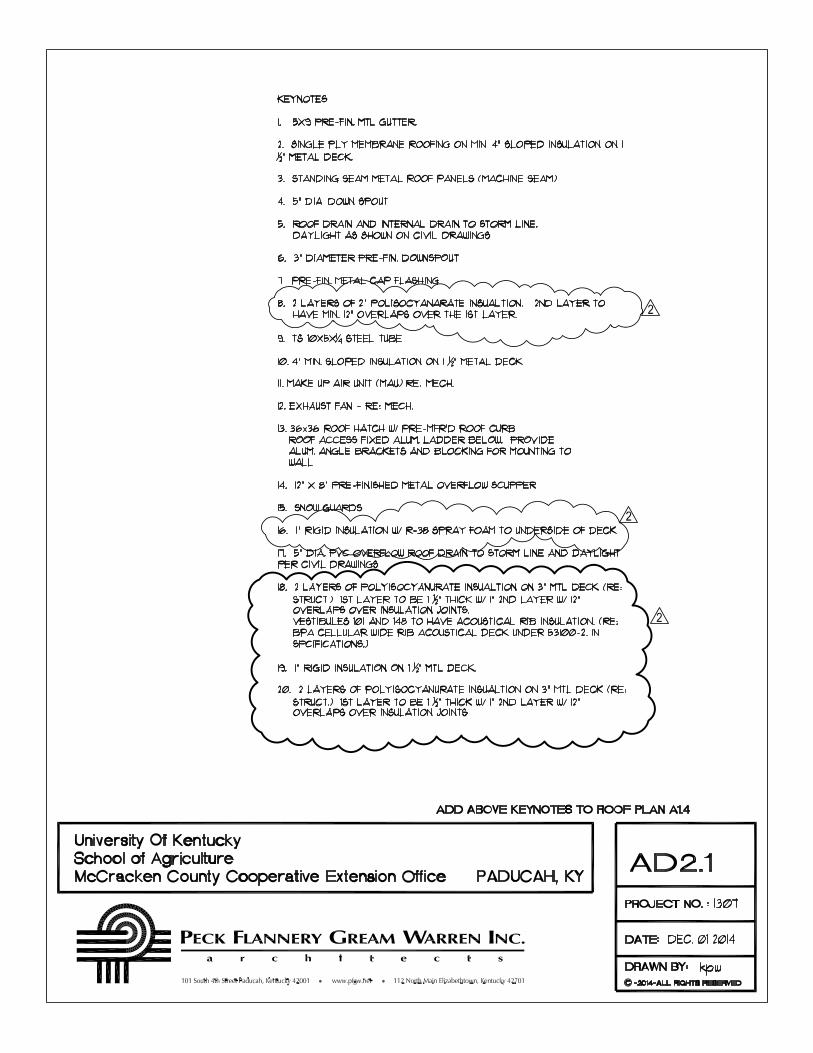
ITEM NO. 9: DRAWING A1.4 – ROOF PLAN NOTES
Added keynote callouts to help identify roof insulation and type for the various roof areas as shown on attached sketches, AD2.1, AD2.2, and AD2.3.

PFGW File No. 1307 University of Kentucky College of Agriculture McCracken County Cooperative Extension Office Paducah, Kentucky
ADDENDUM NO. 2 009002 - 4
ITEM NO. 10: DRAWINGS U1.1 AND E3.1.
The Electrical Utility fees shall be removed from the Contract. The Owner, not the Contractor, shall be responsible for paying all utility company fees associated with the new electrical service
ITEM NO. 11: DRAWING H1.1, ATTACHED SKETCHES XH01 AND XH02.
Contractor shall install grilles and diffusers per the tags as indicated on the attached sketches. Air balance shall be completed using the airflows listed on Sketches XH01 and XH02.
ITEM NO. 12: DRAWING H5.1- INTAKE AND RELIEF HOOD SCHEDULE
Update manufacturers list to include Twin City as an approved manufacturer. Final approval shall be reserved for Shop Drawing review.
ATTACHMENTS
1. Specification Section 232113
2. AD2.1
3. AD2.2
4. AD2.3
5. Sketch XH01
6. Sketch XH02
END OF ADDENDUM NO. 2

PFGW File No. 1307 University of Kentucky College of Agriculture
McCracken County Cooperative Extension Office
Paducah, Kentucky
HYDRONIC PIPING 232113. 1
SECTION 232113 . HYDRONIC PIPING
PART 1 . GENERAL
1.1 SUMMARY
A. This Section includes pipe and fitting materials, joining methods, special.duty valves, and
specialties for the following:
1. Condenser.water piping.
2. Makeup.water piping.
3. Condensate.drain piping.
4. Air.vent piping.
5. Glycol.
B. Refer to Section “HVAC Water Treatment” for Additional Information.
1.2 PERFORMANCE REQUIREMENTS
A. Hydronic piping components and installation shall be capable of withstanding the following
minimum working pressure and temperature:
1. Condenser.Water Piping: 150 psig at 150 deg F.
2. Makeup.Water Piping: 80 psig at 150 deg F.
3. Condensate.Drain Piping: 150 deg F.
4. Air.Vent Piping: 200 deg F.
1.3 SUBMITTALS
A. Product Data: For each type of the following:
1. Pipe and fittings.
2. Valves. Include flow and pressure drop curves based on manufacturer's testing for
control valves.
3. Air control devices.
4. Chemical treatment.
5. Hydronic specialties.
B. Operation and maintenance data.

PFGW File No. 1307 University of Kentucky College of Agriculture
McCracken County Cooperative Extension Office
Paducah, Kentucky
HYDRONIC PIPING 232113. 2
1.4 QUALITY ASSURANCE
A. ASME Compliance: Comply with ASME B31.9, "Building Services Piping," for materials,
products, and installation. Safety valves and pressure vessels shall bear the appropriate ASME
label. Fabricate and stamp air separators and expansion tanks to comply with ASME Boiler and
Pressure Vessel Code: Section VIII, Division 1.
PART 2 . PRODUCTS
2.1 COPPER TUBE AND FITTINGS
A. Drawn.Temper Copper Tubing: ASTM B 88, Type L.
B. Wrought.Copper Fittings: ASME B16.22.
C. Wrought.Copper Unions: ASME B16.22.
2.2 STEEL PIPE AND FITTINGS
A. Steel Pipe: ASTM A 53, black steel with plain ends; type, grade, and wall thickness as
indicated in Part 3 "Piping Applications" Article.
B. Forged.Steel Flanges and Flanged Fittings: ASME B16.5, including bolts, nuts, and gaskets of
the following material group, end connections, and facings:
1. Material Group: 1.1.
2. End Connections: Butt welding.
3. Facings: Raised face.
C. Grooved Mechanical.Joint Fittings and Couplings:
1. Manufacturers: Subject to compliance with requirements, provide products by one of the
following:
a. Anvil International, Inc.
b. Tyco Fire & Building Products.
c. Victaulic Company of America.
d. Approved equal.
2. Joint Fittings: ASTM A 536, Grade 65.45.12 ductile iron; ASTM A 47, Grade 32510
malleable iron; ASTM A 53, Type F, E, or S, Grade B fabricated steel; or ASTM A 106,
Grade B steel fittings with grooves or shoulders constructed to accept grooved.end
couplings; with nuts, bolts, locking pin, locking toggle, or lugs to secure grooved pipe
and fittings.
PFGW File No. 1307 University of Kentucky College of Agriculture
McCracken County Cooperative Extension Office
Paducah, Kentucky
HYDRONIC PIPING 232113. 3
3. Couplings: Ductile. or malleable.iron housing and synthetic rubber gasket of central
cavity pressure.responsive design; with nuts, bolts, locking pin, locking toggle, or lugs to
secure grooved pipe and fittings.
D. Branch Line Fittings:
1. Manufacturers: Subject to compliance with requirements, provide products by one of the
following:
a. Anvil International, Inc.
b. Tyco Fire & Building Products.
c. Victaulic Company of America.
d. Approved equal.
2. Pressure Rating: 175 psig minimum.
3. Body Material: Steel
4. Type: Weld.o.lets or thread.o.lets.
5. Configurations: Fully welded to main, with welded or threaded connection. Refer to
“Piping Applications” for connection method.
6. Size: Of dimension to fit onto hydronic main and with outlet connections as required to
match connected branch piping.
7. Branch Outlets: Grooved or threaded.
2.3 JOINING MATERIALS
A. Joining materials as specified in Section “Common Work Results for Mechanical”.
2.4 DIELECTRIC FITTINGS
A. Dielectric Fittings are specified in Section “Common Work Results for Mechanical”.
2.5 VALVES
A. General duty valves are specified in Section “General.Duty Valves for Mechanical Piping”.
B. Automatic flow control valves are specified in Section “Instrumentation and Control for
HVAC”.
C. Diaphragm.Operated, Pressure.Reducing Valves:
1. Manufacturers: Subject to compliance with requirements, provide products by one of the
following:
a. Armstrong Pumps, Inc.
b. Bell & Gossett.
c. Patterson Pump Company.
PFGW File No. 1307 University of Kentucky College of Agriculture
McCracken County Cooperative Extension Office
Paducah, Kentucky
HYDRONIC PIPING 232113. 4
d. Approved equal.
2. Body: Bronze or brass.
3. Disc: Glass and carbon.filled PTFE.
4. Seat: Brass.
5. Stem Seals: EPDM O.rings.
6. Diaphragm: EPT.
7. Low inlet.pressure check valve.
8. Inlet Strainer: Stainless steel, removable without system shutdown.
9. Valve Seat and Stem: Noncorrosive.
10. Valve Size, Capacity, and Operating Pressure: Selected to suit system in which installed,
with operating pressure and capacity factory set and field adjustable.
2.6 AIR CONTROL DEVICES
A. Manufacturers: Subject to compliance with requirements, provide products by one of the
following:
1. Amtrol, Inc.
2. Armstrong Pumps, Inc.
3. Bell & Gossett.
4. Patterson Pump Company.
5. Approved equal.
B. Manual Air Vents:
1. Body: Cast Iron.
2. Internal Parts: Nonferrous.
3. Operator: Screwdriver or thumbscrew.
4. Inlet Connection: NPS 1/2.
5. Discharge Connection: NPS 1/8.
6. CWP Rating: 150 psig.
7. Maximum Operating Temperature: 225 deg F.
C. Expansion Tanks:
1. Tank: Welded steel, rated for 125.psig working pressure and 375 deg F maximum
operating temperature, with taps in bottom of tank for tank fitting and taps in end of tank
for gage glass.
2. Air.Control Tank Fitting: Cast.iron body, copper.plated tube, brass vent tube plug, and
stainless.steel ball check, sized for expansion.tank diameter. Provide tank fittings for
125.psig working pressure and 250 deg F maximum operating temperature.
3. Tank Drain Fitting: Brass body, nonferrous internal parts; 125.psig working pressure and
240 deg F maximum operating temperature; constructed to admit air into expansion tank,
drain water, and close off system.
D. In.Line Air/Dirt Separators:

PFGW File No. 1307 University of Kentucky College of Agriculture
McCracken County Cooperative Extension Office
Paducah, Kentucky
HYDRONIC PIPING 232113. 5
1. Tank: One.piece cast iron with an integral weir constructed to decelerate system flow to
maximize air separation and sediment trap to capture and contain distilled foreign matter
in hydronic system.
2. Maximum Working Pressure: Up to 175 psig.
3. Maximum Operating Temperature: Up to 300 deg F.
2.7 CHEMICAL TREATMENT
A. Bypass Chemical Feeder: Welded steel construction; 125.psig working pressure; 5.gal.
capacity; with fill funnel and inlet, outlet, and drain valves. Reference Section “HVAC Water
Treatment” for coordination.
1. Chemicals: Specially formulated, based on analysis of makeup water, to prevent
accumulation of scale and corrosion in piping and connected equipment.
B. Propylene Glycol: Industrial grade with corrosion inhibitors and environmental.stabilizer
additives for mixing with water in systems indicated to contain antifreeze or glycol solutions.
2.8 HYDRONIC PIPING SPECIALTIES
A. Stainless.Steel Bellow, Flexible Connectors:
1. Body: Stainless.steel bellows with woven, flexible, bronze, wire.reinforcing protective
jacket.
2. End Connections: Threaded or flanged to match equipment connected.
3. Performance: Capable of 3/4.inch misalignment.
4. CWP Rating: 150 psig.
5. Maximum Operating Temperature: 250 deg F.
PART 3 . EXECUTION
3.1 PIPING APPLICATIONS
A. Condenser.water piping, aboveground, NPS 2 and smaller, shall be the following:
1. Type L, drawn.temper copper tubing, wrought.copper fittings, and soldered joints.
B. Condenser.water piping, aboveground, NPS 2.1/2 and larger, shall be the following:
1. Schedule 40 steel pipe; grooved, mechanical joint coupling and fittings; and grooved,
mechanical joints.
C. Makeup.water piping installed aboveground shall be the following:
1. Type L, drawn.temper copper tubing, wrought.copper fittings, and soldered joints.
PFGW File No. 1307 University of Kentucky College of Agriculture
McCracken County Cooperative Extension Office
Paducah, Kentucky
HYDRONIC PIPING 232113. 6
D. Condensate.Drain Piping:
1. Schedule 40 PVC with solvent welded joints and fittings.
E. Air.Vent Piping:
1. Inlet: Same as service where installed.
2. Outlet: Type K, annealed.temper copper tubing with soldered joints.
3.2 VALVE APPLICATIONS
A. Install shutoff.duty valves at each branch connection to supply mains, and at supply connection
to each piece of equipment as specified.
B. Install automatic flow control valves in the return pipe of each heating or cooling terminal as
specified.
C. Install check valves at each pump discharge and elsewhere as required to control flow direction
as specified.
D. Install pressure.reducing valves at makeup.water connection to regulate system fill pressure as
specified.
3.3 PIPING INSTALLATIONS
A. Drawing plans, schematics, and diagrams indicate general location and arrangement of piping
systems. Indicate piping locations and arrangements if such were used to size pipe and
calculate friction loss, expansion, pump sizing, and other design considerations. Install piping
as indicated unless deviations to layout are approved on Coordination Drawings.
B. Install piping in concealed locations, unless otherwise indicated and except in equipment rooms
and service areas.
C. Install piping indicated to be exposed and piping in equipment rooms and service areas at right
angles or parallel to building walls. Diagonal runs are prohibited unless specifically indicated
otherwise.
D. Install piping above accessible ceilings to allow sufficient space for ceiling panel removal.
E. Install piping to permit valve servicing.
F. Install piping at indicated slopes.
G. Install piping free of sags and bends.
H. Install fittings for changes in direction and branch connections.

PFGW File No. 1307 University of Kentucky College of Agriculture
McCracken County Cooperative Extension Office
Paducah, Kentucky
HYDRONIC PIPING 232113. 7
I. Install piping to allow application of insulation.
J. Select system components with pressure rating equal to or greater than system operating
pressure.
K. Install groups of pipes parallel to each other, spaced to permit applying insulation and servicing
of valves.
L. Install drains, consisting of a tee fitting, NPS 3/4 ball valve, and short NPS 3/4 threaded nipple
with cap, at low points in piping system mains and elsewhere as required for system drainage.
M. Install piping at a uniform grade of 0.2 percent upward in direction of flow.
N. Reduce pipe sizes using eccentric reducer fitting installed with level side up.
O. Install branch connections to mains using manufactured fittings in main pipe, with the branch
connected to the main pipe.
P. Install unions in piping, NPS 2 and smaller, adjacent to valves, at final connections of
equipment, and elsewhere as indicated.
Q. Install flanges in piping, NPS 2.1/2 and larger, at final connections of equipment and elsewhere
as indicated.
R. Identify piping as to contents and flow direction as specified in Section “Identification for
Mechanical Piping and Equipment”.
3.4 HANGERS AND SUPPORTS
A. Install the following pipe attachments:
1. Adjustable steel clevis hangers for individual horizontal piping.
2. Provide copper.clad hangers and supports for hangers and supports in direct contact with
copper pipe.
B. Install hangers for steel piping with the following maximum spacing and minimum rod sizes:
1. NPS 2.1/2: Maximum span, 11 feet; minimum rod size, 1/2 inch.
2. NPS 3: Maximum span, 12 feet; minimum rod size, 1/2 inch.
3. NPS 4: Maximum span, 8 feet; minimum rod size, 5/8 inch.
4. NPS 6: Maximum span, 8 feet, minimum rod size, 3/4 inch.
5. NPS 8: Maximum span, 19 feet, minimum rod size, 7/8 inch.
6. NPS 10: Maximum span, 20 feet, minimum rod size, 7/8 inch.
7. NPS 12: Maximum span, 23 feet, minimum rod size, 7/8 inch.
C. Install hangers for drawn.temper copper piping with the following maximum spacing and
minimum rod sizes:
PFGW File No. 1307 University of Kentucky College of Agriculture
McCracken County Cooperative Extension Office
Paducah, Kentucky
HYDRONIC PIPING 232113. 8
1. NPS 3/4: Maximum span, 5 feet; minimum rod size, 3/8 inch.
2. NPS 1: Maximum span, 6 feet; minimum rod size, 3/8 inch.
3. NPS 1.1/2: Maximum span, 8 feet; minimum rod size, 3/8 inch.
4. NPS 2: Maximum span, 8 feet; minimum rod size, 3/8 inch.
D. Support vertical runs at each floor, and at 10.foot intervals between floors.
3.5 PIPE JOINT CONSTRUCTION
A. Pipe joint construction is specified in Section “Common Work Results for Mechanical”.
3.6 HYDRONIC SPECIALTIES INSTALLATION
A. Install manual air vents at all high points in piping, at heat.transfer coils, and elsewhere as
required for system air venting.
B. Install piping from air separator or air purger to expansion tank with a 2 percent upward slope
toward tank.
C. Install in.line air separators in pump suction. Install drain valve on air separators NPS 2 and
larger.
D. Install bypass chemical feeder in hydronic system where indicated, in upright position with top
of funnel not more than 48 inches above the floor. Install feeder in minimum NPS 3/4 bypass
line, from main with full.size, full.port, ball valve in the main between bypass connections.
Install NPS 3/4 pipe from chemical feeder drain, to nearest equipment drain and include a full.
size, full.port, ball valve.
E. Install expansion tanks above the air separator. Install tank fitting in tank bottom and charge
tank. Use manual vent for initial fill to establish proper water level in tank.
1. Install tank fittings that are shipped loose.
2. Support tank from structure above with sufficient strength to carry weight of tank, piping
connections, fittings, plus tank full of water. Do not overload building components and
structural members.
3.7 TERMINAL EQUIPMENT CONNECTIONS
A. Sizes for supply and return piping connections shall be the same as or larger than equipment
connections.
B. Install control valves in accessible locations close to connected equipment.
C. Install ports for pressure gages and thermometers at coil inlet and outlet connections.

PFGW File No. 1307 University of Kentucky College of Agriculture
McCracken County Cooperative Extension Office
Paducah, Kentucky
HYDRONIC PIPING 232113. 9
3.8 CHEMICAL TREATMENT
A. Fill system with fresh water and add liquid alkaline compound with emulsifying agents and
detergents to remove grease and petroleum products from piping. Circulate solution for a
minimum of 24 hours, drain, clean strainer screens, and refill with fresh water.
B. Add initial chemical treatment and maintain water quality in ranges noted above for the first
twelve (12) months of operation. Reference Section “HVAC Water Treatment”.
C. Fill system with glycol solution with the following concentrations:
1. Condenser.Water Piping: Minimum ten (10) percent propylene glycol.
3.9 FIELD QUALITY CONTROL
A. Prepare hydronic piping according to ASME B31.9 and as follows:
1. Leave joints un.insulated and exposed for examination during test.
2. Provide temporary restraints for expansion joints that cannot sustain reactions due to test
pressure. If temporary restraints are impractical, isolate expansion joints from testing.
3. Flush hydronic piping systems with clean water; then remove and clean or replace
strainer screens.
4. Isolate equipment from piping. If a valve is used to isolate equipment, its closure shall be
capable of sealing against test pressure without damage to valve. Install blinds in flanged
joints to isolate equipment.
5. Install safety valve, set at a pressure no more than one.third higher than test pressure, to
protect against damage by expanding liquid or other source of overpressure during test.
B. Perform the following tests on hydronic piping:
1. Use ambient temperature water as a testing medium unless there is risk of damage due to
freezing. Another liquid that is safe for workers and compatible with piping may be
used.
2. While filling system, use vents installed at high points of system to release air. Use
drains installed at low points for complete draining of test liquid.
3. Isolate expansion tanks and determine that hydronic system is full of water.
4. Subject piping system to hydrostatic test pressure that is not less than 1.5 times the
system's working pressure. Test pressure shall not exceed maximum pressure for any
vessel, pump, valve, or other component in system under test. Verify that stress due to
pressure at bottom of vertical runs does not exceed 90 percent of specified minimum
yield strength or 1.7 times "SE" value in Appendix A in ASME B31.9, "Building
Services Piping."
5. After hydrostatic test pressure has been applied for at least 10 minutes, examine piping,
joints, and connections for leakage. Eliminate leaks by tightening, repairing, or replacing
components and repeat hydrostatic test until there are no leaks.
6. Prepare written report of testing.
C. Perform the following before operating the system:
PFGW File No. 1307 University of Kentucky College of Agriculture
McCracken County Cooperative Extension Office
Paducah, Kentucky
HYDRONIC PIPING 232113. 10
1. Open manual valves fully.
2. Inspect pumps for proper rotation.
3. Set makeup pressure.reducing valves for required system pressure.
4. Inspect air vents at high points of system and determine if all are installed and operating
freely (automatic type), or bleed air completely (manual type).
5. Set temperature controls so all coils are calling for full flow.
6. Verify lubrication of motors and bearings.
END OF SECTION 232113


S-2200
S-8135
S-8135
S-8135
S-8135
S-8135
S-8135
S-8135
S-8135
S-8135
S-8130
S-8135
S-8130
S-8135
S-8135
S-8135
S-8130
S-8130
S-8130
R-41600
S-8130
S-8135
S-8130
S-8130
S-8135
S-8135
S-8130
S-8135
S-8135
S-8135
S-8135
S-8135
S-8135
S-8130
S-8135
S-8130
S-8135
S-8130
S-8135
S-8135
S-8135
S-8135
S-8135
S-8135
S-8130
S-8135
S-8135
S-8130
S-8130
S-8130
R-41600
1
1
1 2
2
DN
.
UP
2
R-41600
UP
R-41600
1
2
11
9
10
10
10
THP-4
T HP-61
T HP-5
10
9
UNIVERSITY OF KENTUCKYSCHOOL OF AGRICULTUREMcCracken County Extension OfficeNEW HOLT RD. PADUCAH, KY
REFERENCE DRAWING - H1.1

S-2
195
S-2
200
S-2
200
S-2
200
S-2
200
S-2
200
S-2
200
R-1
1995
S-4
200
S-3
250
200
S-2
200
S-2
200
S-2
200
S-2
200
DN.
R-2
1200
R-2
1200
8
8
DN.
DN.
EF 3
54
DN.
10x1
0 EA
E-1
350
E-1
350
UP
UP
1919
S-3
250
UP
T
HP-9
TH
P-6
10x1
0 EA
UP
EF 6
EF 7
7
6
UNIVERSITY OF KENTUCKYSCHOOL OF AGRICULTUREMcCracken County Extension OfficeNEW HOLT RD. PADUCAH, KY
REFERENCE DRAWING - H1.1