Embed Size (px)
Citation preview
02317-1 Underground Warning Tape
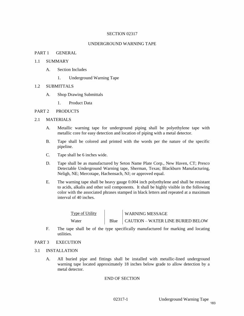
SECTION 02317
UNDERGROUND WARNING TAPE
PART 1 GENERAL
1.1 SUMMARY
A. Section Includes
1. Underground Warning Tape
1.2 SUBMITTALS
A. Shop Drawing Submittals
1. Product Data
PART 2 PRODUCTS
2.1 MATERIALS
A. Metallic warning tape for underground piping shall be polyethylene tape with
metallic core for easy detection and location of piping with a metal detector.
B. Tape shall be colored and printed with the words per the nature of the specific
pipeline.
C. Tape shall be 6 inches wide.
D. Tape shall be as manufactured by Seton Name Plate Corp., New Haven, CT; Presco
Detectable Underground Warning tape, Sherman, Texas; Blackburn Manufacturing,
Neligh, NE; Mercotape, Hachensach, NJ; or approved equal.
E. The warning tape shall be heavy gauge 0.004 inch polyethylene and shall be resistant
to acids, alkalis and other soil components. It shall be highly visible in the following
color with the associated phrases stamped in black letters and repeated at a maximum
interval of 40 inches.
Type of Utility 1 2 WARNING MESSAGE
Water Blue CAUTION – WATER LINE BURIED BELOW
F. The tape shall be of the type specifically manufactured for marking and locating
utilities.
PART 3 EXECUTION
3.1 INSTALLATION
A. All buried pipe and fittings shall be installed with metallic-lined underground
warning tape located approximately 18 inches below grade to allow detection by a
metal detector.
END OF SECTION
183
02320-1 Borrow Materials
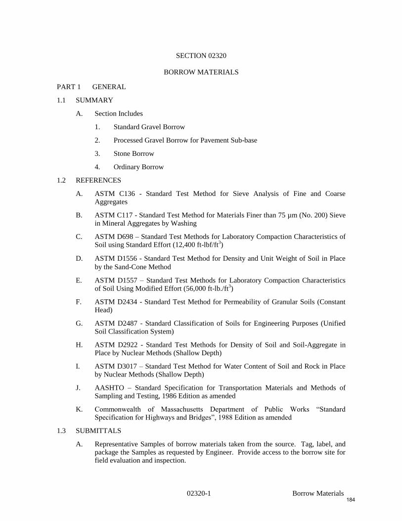
SECTION 02320
BORROW MATERIALS
PART 1 GENERAL
1.1 SUMMARY
A. Section Includes
1. Standard Gravel Borrow
2. Processed Gravel Borrow for Pavement Sub-base
3. Stone Borrow
4. Ordinary Borrow
1.2 REFERENCES
A. ASTM C136 - Standard Test Method for Sieve Analysis of Fine and Coarse Aggregates
B. ASTM C117 - Standard Test Method for Materials Finer than 75 µm (No. 200) Sieve in Mineral Aggregates by Washing
C. ASTM D698 – Standard Test Methods for Laboratory Compaction Characteristics of Soil using Standard Effort (12,400 ft-lbf/ft
3)
D. ASTM D1556 - Standard Test Method for Density and Unit Weight of Soil in Place
by the Sand-Cone Method
E. ASTM D1557 – Standard Test Methods for Laboratory Compaction Characteristics of Soil Using Modified Effort (56,000 ft-lb./ft
3)
F. ASTM D2434 - Standard Test Method for Permeability of Granular Soils (Constant Head)
G. ASTM D2487 - Standard Classification of Soils for Engineering Purposes (Unified Soil Classification System)
H. ASTM D2922 - Standard Test Methods for Density of Soil and Soil-Aggregate in Place by Nuclear Methods (Shallow Depth)
I. ASTM D3017 – Standard Test Method for Water Content of Soil and Rock in Place by Nuclear Methods (Shallow Depth)
J. AASHTO – Standard Specification for Transportation Materials and Methods of Sampling and Testing, 1986 Edition as amended
K. Commonwealth of Massachusetts Department of Public Works “Standard Specification for Highways and Bridges”, 1988 Edition as amended
1.3 SUBMITTALS
A. Representative Samples of borrow materials taken from the source. Tag, label, and package the Samples as requested by Engineer. Provide access to the borrow site for field evaluation and inspection.
184
02320-2 Borrow Materials
B. Provide sieve analysis (ASTM C136) and permeability analysis (ASTM D2434) from certified soils testing laboratory for all borrow materials. Take and test a sample, at no additional cost to the Owner for each 1,500 c.y. of borrow material placed.
C. Provide standard proctor analysis (ASTM D698) from certified soils testing laboratory for all borrow materials.
1.4 QUALITY ASSURANCE
A. No borrow shall be placed prior to the approval of Samples by the Engineer.
1.5 PROJECT/SITE CONDITIONS
A. Existing Conditions
1. Comply with any environmental requirements and restrictions.
2. Keep all public and private roadway surfaces clean during hauling operations and promptly and thoroughly remove any borrow or other debris that may be brought upon the surface before it becomes compacted by traffic. Frequently clean and keep clean the wheels of all vehicles used for hauling to avoid bringing any dirt upon the paved surfaces.
PART 2 PRODUCTS
2.1 STANDARD GRAVEL BORROW
A. Gravel borrow shall consist of inert material that is hard, durable stone and coarse sand, free from loam and clay, surface coatings, and deleterious materials. The coarse aggregate shall have a percentage of wear, by the Los Angeles Abrasion Test, of not more than 50.
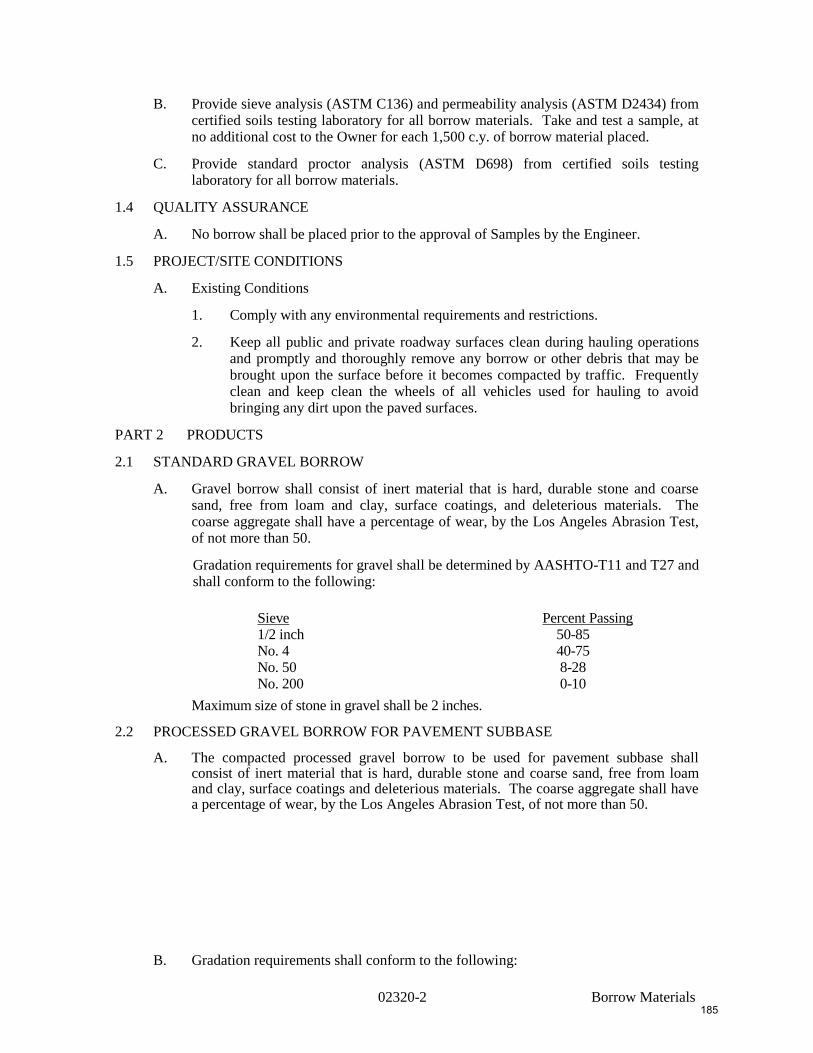
Gradation requirements for gravel shall be determined by AASHTO-T11 and T27 and shall conform to the following:
Sieve Percent Passing 1/2 inch 50-85 No. 4 40-75 No. 50 8-28 No. 200 0-10
Maximum size of stone in gravel shall be 2 inches.
2.2 PROCESSED GRAVEL BORROW FOR PAVEMENT SUBBASE
A. The compacted processed gravel borrow to be used for pavement subbase shall consist of inert material that is hard, durable stone and coarse sand, free from loam and clay, surface coatings and deleterious materials. The coarse aggregate shall have a percentage of wear, by the Los Angeles Abrasion Test, of not more than 50.
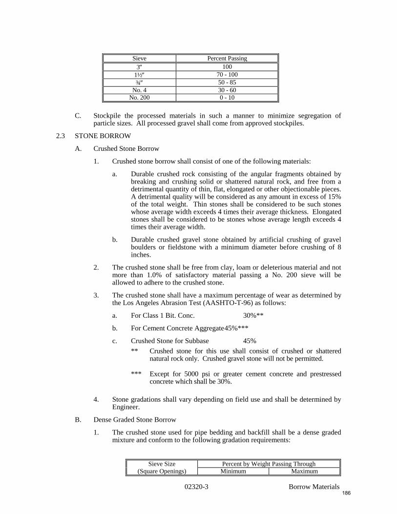
B. Gradation requirements shall conform to the following:
185
02320-3 Borrow Materials
Sieve Percent Passing
3 100
1½ 70 - 100
¾ 50 - 85
No. 4 30 - 60
No. 200 0 - 10
C. Stockpile the processed materials in such a manner to minimize segregation of particle sizes. All processed gravel shall come from approved stockpiles.
2.3 STONE BORROW
A. Crushed Stone Borrow
1. Crushed stone borrow shall consist of one of the following materials:
a. Durable crushed rock consisting of the angular fragments obtained by breaking and crushing solid or shattered natural rock, and free from a detrimental quantity of thin, flat, elongated or other objectionable pieces. A detrimental quality will be considered as any amount in excess of 15% of the total weight. Thin stones shall be considered to be such stones whose average width exceeds 4 times their average thickness. Elongated stones shall be considered to be stones whose average length exceeds 4 times their average width.
b. Durable crushed gravel stone obtained by artificial crushing of gravel boulders or fieldstone with a minimum diameter before crushing of 8 inches.
2. The crushed stone shall be free from clay, loam or deleterious material and not more than 1.0% of satisfactory material passing a No. 200 sieve will be allowed to adhere to the crushed stone.
3. The crushed stone shall have a maximum percentage of wear as determined by the Los Angeles Abrasion Test (AASHTO-T-96) as follows:
a. For Class 1 Bit. Conc. 30%**
b. For Cement Concrete Aggregate 45%***
c. Crushed Stone for Subbase 45%
** Crushed stone for this use shall consist of crushed or shattered natural rock only. Crushed gravel stone will not be permitted.
*** Except for 5000 psi or greater cement concrete and prestressed concrete which shall be 30%.
4. Stone gradations shall vary depending on field use and shall be determined by Engineer.
B. Dense Graded Stone Borrow
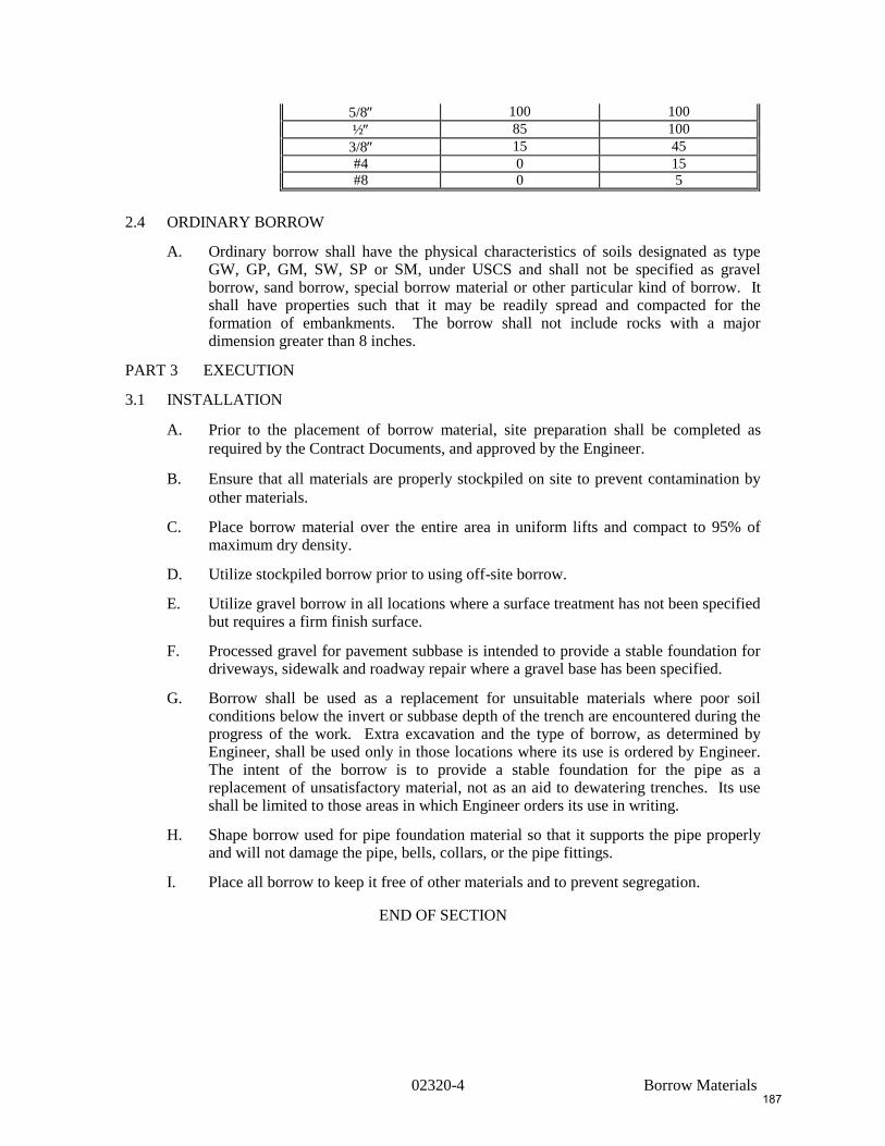
1. The crushed stone used for pipe bedding and backfill shall be a dense graded mixture and conform to the following gradation requirements:
Sieve Size Percent by Weight Passing Through (Square Openings) Minimum Maximum
186
02320-4 Borrow Materials
5/8 100 100
½ 85 100
3/8 15 45
#4 0 15
#8 0 5
2.4 ORDINARY BORROW
A. Ordinary borrow shall have the physical characteristics of soils designated as type GW, GP, GM, SW, SP or SM, under USCS and shall not be specified as gravel borrow, sand borrow, special borrow material or other particular kind of borrow. It shall have properties such that it may be readily spread and compacted for the formation of embankments. The borrow shall not include rocks with a major dimension greater than 8 inches.
PART 3 EXECUTION
3.1 INSTALLATION
A. Prior to the placement of borrow material, site preparation shall be completed as
required by the Contract Documents, and approved by the Engineer.
B. Ensure that all materials are properly stockpiled on site to prevent contamination by
other materials.
C. Place borrow material over the entire area in uniform lifts and compact to 95% of maximum dry density.
D. Utilize stockpiled borrow prior to using off-site borrow.
E. Utilize gravel borrow in all locations where a surface treatment has not been specified but requires a firm finish surface.
F. Processed gravel for pavement subbase is intended to provide a stable foundation for driveways, sidewalk and roadway repair where a gravel base has been specified.
G. Borrow shall be used as a replacement for unsuitable materials where poor soil conditions below the invert or subbase depth of the trench are encountered during the progress of the work. Extra excavation and the type of borrow, as determined by Engineer, shall be used only in those locations where its use is ordered by Engineer. The intent of the borrow is to provide a stable foundation for the pipe as a replacement of unsatisfactory material, not as an aid to dewatering trenches. Its use shall be limited to those areas in which Engineer orders its use in writing.
H. Shape borrow used for pipe foundation material so that it supports the pipe properly and will not damage the pipe, bells, collars, or the pipe fittings.
I. Place all borrow to keep it free of other materials and to prevent segregation.
END OF SECTION
187
02410-1
SECTION 02410
ROCK EXCAVATION
PART 1 GENERAL
1.1 SUMMARY
A. Section Includes
1. Rock excavation for trenches and structures.
B. Related Sections
1. Section 02315 – Excavation, Backfilling and Compaction
1.2 DESCRIPTION
A. Removal of boulders greater than one (1) cubic yard in volume is included under this
Section of work. Removal of boulders under one (1) cubic yard in volume is not
considered part of this work and is considered a part of the work specified under
Section 02315.
B. Rock excavation shall mean solid ledge rock or solid concrete which in the opinion of
the Engineer requires for its removal, drilling and blasting, wedging, sledging, firing,
or breaking up with power operated hand tools.
C. Material removed solely with a power-operated excavator or loose, previously blasted
ledge, broken stone, weathered rock or glacial till will not be considered rock
excavation. Rock excavation shall not include cemented gravel or hardpan.
D. Minimum payment depth for rock which is encountered in a trench will not be less
than three (3) feet.
1.3 SUBMITTALS
A. Submit construction methods which will be utilized for the removal of rock on the
project.
B. Submit qualifications of professional blasting Consultant.
C. Prior to beginning any blasting operation, submit a detailed description of the
proposed method for blasting.
PART 2 PRODUCTS
NOT USED
PART 3 EXECUTION
A. Blasting
1. Comply with State and Local regulations when blasting and handling
explosives.
2. Assume full responsibility for the safety of the blasting operations and perform
the work in a manner that will ensure the safety of personnel and that of
existing structures, adjacent buildings, and completed new construction. The
Contractor will be held responsible for claims for damage to property and
underground structures. Repair in kind utilities, pipelines or house services
damaged while conducting pre-drilling and blasting activities. Repair and
maintain roadway and paved surfaces that are cracked or damaged during the
course of pre-drilling and blasting. The pay limits for paving repair shall be as
noted, regardless of the limits of necessary roadway repairs due to blasting.
3. Comply with current OSHA regulations as well as engage the services of a
qualified, professional blasting Consultant who will design, review, evaluate
and modify the blasting operations. Design the initial blasts and conduct test
188
02410-2
blasts (minimum four tests) until regular production controlled blast patterns
are developed that produce the desired rate of excavation while meeting the
requirements for vibration and air blast control specified. Periodically, or when
requested by the Engineer, review the blasting operations and make such
changes in the blasting operations as are required to produce a controlled
blasting operation meeting the requirements of these specifications. Review by
the Engineer of the Contractor's blast design shall not relieve the responsibility
for obtaining adequate rock breakage.
4. Provide adequate notice to residents that may be effected by the use of
explosives. In residential areas, provide the following:
a. Certificate of Insurance to cover a blasting operation.
b. Evidence that residential homes have been reviewed to satisfy all parties
that pre-construction conditions are well documented.
5. Blasting Design Criteria
a. Exercise care in the drilling and blasting operations so that the remaining
rock remains stable and to reduce overbreak to a minimum.
b. Control blasting by limiting the charge per delay to that which produces
limited levels of ground vibrations as herein specified. Hire a qualified
testing agency to measure the radial particle velocities using a
seismograph. Peak radial particle velocity shall be the measure of the
level of vibration.
c. The charge weight per delay used in blasting shall be such that the peak
radial particle velocity shall not exceed 2.0 inches per second measured
on the foundation material, rock, or overburden at the nearest structure.
The Contractor shall modify the size and type of explosives used to meet
this criteria or other limiting criteria.
d. For areas where controlled blasting is required, the charge weight per
delay shall be such that the peak radial particle velocity shall not exceed
1.0 inch per second.
e. Air blast overpressures from blasting operations shall not exceed 0.02
psi.
f. The maximum depth of lift to be removed at any one time shall not
exceed 6 feet.
g. Use blasting mats, chained logs, warning signs, guards, etc., in
accordance with the best practice.
h. All blasting operations shall be done by electrical detonation.
i. Restrict blasting to daylight hours. In no case will blasting operations be
permitted before 8:00 AM or after 5:00 PM.
j. These criteria may be adjusted by OWNER, if the blasting procedures
based on monitoring results or in the opinion of OWNER are likely to be
disruptive to nearby businesses, people, or to cause damage to structures.
These changes may require the Contractor to revise blast design and
reduce the size of charges.
6. In areas where the Contractor is allowed to pre-drill and blast ledge or rock
formations without first removing the over-burden, the Contractor shall be
required to firmly establish a profile of the solid ledge or rock that cannot be
ripped free by the excavating machine. The actual pay quantities will be based
on the inspector's determination of the actual profile and extent of the rock
189
02410-3
formations drilled and blasted by the Contractor and his verification of the rock
formations once the trench has been opened.
B. Minimum excavation and clearance within rock trenches shall be per Section 02315.
C. Minimum pipe bedding requirements shall be per Section 02315.
END OF SECTION
J:\L\L0175\SPEC-2004\02410.DOC
190
02503-1 Testing of Sanitary Sewer and
Storm Drainage Systems
SECTION 02503
TESTING OF SANITARY SEWER AND STORM DRAINAGE SYSTEMS
PART 1 GENERAL
1.1 SUMMARY
A. Section Includes
1. Testing of Gravity Sewer Systems
2. Testing of Pressure Sewer systems
PART 2 PRODUCTS
Not Used
PART 3 EXECUTION
3.1 TESTING OF GRAVITY SEWER SYSTEMS
A. All gravity sewers shall be tested for allowable leakage by low pressure air test or by
an infiltration or exfiltration water test as described herein.
B. Low Pressure Air Test
1. After completing backfill of a section of pipe, conduct a Line Acceptance Test
using low-pressure air. The test shall be performed according to the specified
procedures and under the supervision of the Engineer. Testing procedures
noted in the following paragraph shall be explicitly followed.
2. Pneumatic plugs shall be seal tested before being used in the actual test
installation. One length of pipe shall be laid on the ground and sealed at both
ends with the pneumatic plugs to be checked. Air shall be introduced into the
plugs to 25 psig. The sealed pipe shall be pressurized to 5 psig. The plugs
shall hold against this pressure without bracing and without movement of the
plugs out of the pipe.
3. After a manhole reach of pipe has been backfilled and cleaned, and the
pneumatic plugs are checked by the above procedure, the plugs shall be placed
in the line at each manhole and inflated to 25 psig. Low pressure air shall be
introduced into this sealed line until the internal air pressure reaches 4 psig
greater than the average back pressure of any groundwater that may be over the
pipe. At least two minutes shall be allowed for the air pressure to stabilize.
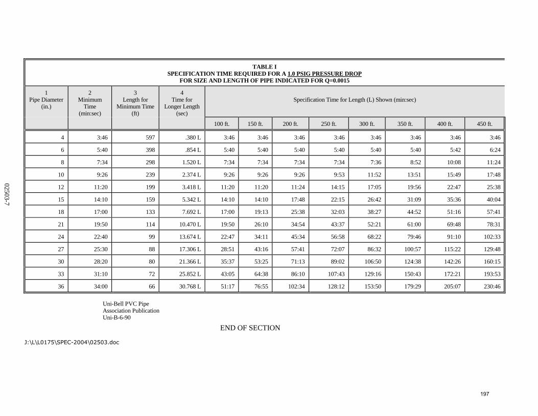
After the stabilization period (3.5 psig minimum pressure in the pipe), the air
hose from the control panel to the air supply shall be disconnected. The
portion of the line being tested shall be termed "Acceptable" if the time
required in minutes for the pressure to decrease from 3.5 to 2.5 psig (greater
than the average back pressure of any groundwater that may be over the pipe)
shall not be less than the time shown for the given diameters and lengths in
Table 1 (at the end of this section).
4. Air tests shall cover a 1.0 psig pressure drop; 0.5 psig pressure drop tests are
not acceptable.
191
02503-2 Testing of Sanitary Sewer and
Storm Drainage Systems
5. In areas where groundwater is known to exist, install a one-half inch diameter
capped pipe nipple, approximately 10 long, through the manhole wall on top
of one of the sewer lines entering the manhole. This shall be done at the time
the sewer line is installed. Immediately prior to Line Acceptance Test, the
groundwater shall be determined by removing the pipe cap, blowing air
through the pipe nipple to remove any obstructions, and then connecting clear
plastic tube to the nipple. The hose shall be held vertically and a measurement
of the height shall be taken after the water has stopped rising in this plastic
tube. The height in feet shall be divided by 2.3 to establish the pressure in
pounds per square inch (psig) that will be added to all readings. (For example,
if the height of water is 11-1/2 feet, then the added pressure will be 5 psig.
This increases the 3.5 psig to 8.5 psig, and the 2.5 psig to 7.5 psig. The
allowable drop of one pound per square inch and the timing remain the same.)
6. The maximum starting test pressure should not exceed 9 psig, regardless of
groundwater level above the pipe. If the groundwater level is such that the
added pressure would be greater than 5.5 psig (12.7 feet), the pipe section may
be tested using a starting pressure of 9 psig.
7. Each pipe nipple installed to measure groundwater levels should be recapped
subsequent to the air testing procedure to prevent future infiltration.
8. As an alternative to installing a pipe nipple in a manhole to measure the height
of groundwater, the Contractor shall excavate a test pit over the pipe to
determine the height of groundwater.
C. Vacuum Test for Manholes - Gravity Sewer Lines
1. After a manhole has been constructed, conduct a Manhole Acceptance Test
using the following vacuum test procedure:
a. Plug all lift holes with an approved non-shrink grout.
b. Plug all pipes entering the manhole, taking care to securely brace the
plug from being drawn into the manhole.
c. The test head shall be placed at the inside of the top of the cone section
and the seal inflated in accordance with the manufacturers'
recommendations.
d. Draw a vacuum of 10 inches of mercury and shut off the vacuum pump.
With the valves closed, the time shall be measured for the vacuum to
drop to 9 inches. The manhole shall pass if the time is greater than:
1 min. 0 sec. for 0-ft. to 10-ft. deep manholes
1 min. 15 sec. for 10-ft. to 15-ft. deep manholes
1 min. 30 sec. for 15-ft. to 25-ft. deep manholes
e. If the manhole fails the initial test, necessary repairs shall be made with
a non-shrink grout. Retesting shall proceed until a satisfactory test is
obtained.
D. Infiltration/Exfiltration Test
192
02503-3 Testing of Sanitary Sewer and
Storm Drainage Systems
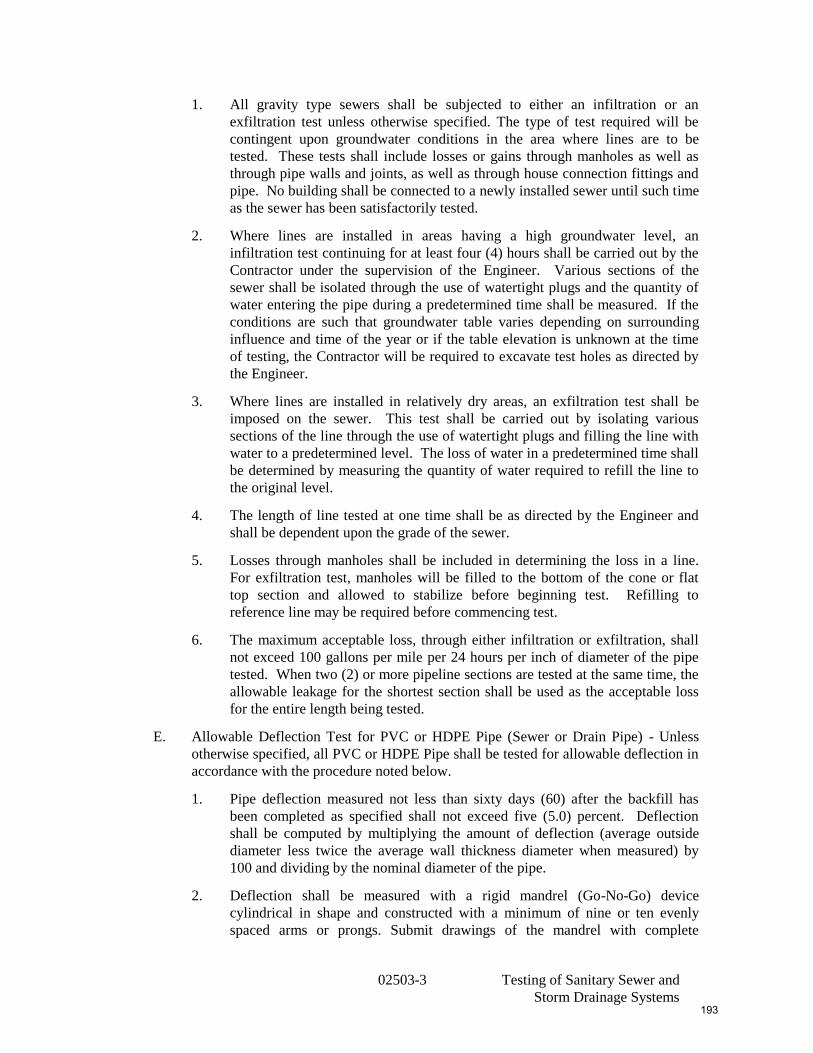
1. All gravity type sewers shall be subjected to either an infiltration or an
exfiltration test unless otherwise specified. The type of test required will be
contingent upon groundwater conditions in the area where lines are to be
tested. These tests shall include losses or gains through manholes as well as
through pipe walls and joints, as well as through house connection fittings and
pipe. No building shall be connected to a newly installed sewer until such time
as the sewer has been satisfactorily tested.
2. Where lines are installed in areas having a high groundwater level, an
infiltration test continuing for at least four (4) hours shall be carried out by the
Contractor under the supervision of the Engineer. Various sections of the
sewer shall be isolated through the use of watertight plugs and the quantity of
water entering the pipe during a predetermined time shall be measured. If the
conditions are such that groundwater table varies depending on surrounding
influence and time of the year or if the table elevation is unknown at the time
of testing, the Contractor will be required to excavate test holes as directed by
the Engineer.
3. Where lines are installed in relatively dry areas, an exfiltration test shall be
imposed on the sewer. This test shall be carried out by isolating various
sections of the line through the use of watertight plugs and filling the line with
water to a predetermined level. The loss of water in a predetermined time shall
be determined by measuring the quantity of water required to refill the line to
the original level.
4. The length of line tested at one time shall be as directed by the Engineer and
shall be dependent upon the grade of the sewer.
5. Losses through manholes shall be included in determining the loss in a line.
For exfiltration test, manholes will be filled to the bottom of the cone or flat
top section and allowed to stabilize before beginning test. Refilling to
reference line may be required before commencing test.
6. The maximum acceptable loss, through either infiltration or exfiltration, shall
not exceed 100 gallons per mile per 24 hours per inch of diameter of the pipe
tested. When two (2) or more pipeline sections are tested at the same time, the
allowable leakage for the shortest section shall be used as the acceptable loss
for the entire length being tested.
E. Allowable Deflection Test for PVC or HDPE Pipe (Sewer or Drain Pipe) - Unless
otherwise specified, all PVC or HDPE Pipe shall be tested for allowable deflection in
accordance with the procedure noted below.
1. Pipe deflection measured not less than sixty days (60) after the backfill has
been completed as specified shall not exceed five (5.0) percent. Deflection
shall be computed by multiplying the amount of deflection (average outside
diameter less twice the average wall thickness diameter when measured) by
100 and dividing by the nominal diameter of the pipe.
2. Deflection shall be measured with a rigid mandrel (Go-No-Go) device
cylindrical in shape and constructed with a minimum of nine or ten evenly
spaced arms or prongs. Submit drawings of the mandrel with complete
193

02503-4 Testing of Sanitary Sewer and
Storm Drainage Systems
dimensions for each diameter of pipe to be tested. Hand pull the mandrel
through all sewer and drain lines.
3. Uncover any section of pipe not passing the mandrel and replace the bedding
and backfill to prevent excessive deflection. Retest repaired pipe until
acceptable.
F. Test Failures
1. In case leakage or deflection exceeds the above specified amount, locate the
failure and repair them at no expense to the Owner.
2. Pipelines with shear-type breaks, fishmouths or damaged gaskets, cracked bells
or couplings, hairline fractures, or structural damage shall be replaced in kind.
Mechanical sleeve couplings, poured concrete collars or similar repairs are not
permitted. The use of pressure grouting repair techniques will not be allowed
without the written consent of the Engineer.
3. After repairs have been made, the line shall be re-tested and the process of
repairing and re-testing shall be repeated until results within the above
specified limits are obtained.
G. Alignment of Gravity Sewers and Drains
1. Gravity sewers and drains shall be laid accurately to line and grade.
2. After completion of the construction, including backfilling, it must be possible
to sight from manhole to manhole THROUGH THE PIPE. This accuracy of
laying the pipe can be easily checked as construction progresses.
3. In the event that the completed main fails to meet the requirement for
alignment because of horizontal displacement, the Contractor will be allowed
to construct intermediate manholes at his own cost. In the event that the
completed sewer main fails to meet the requirement for alignment because of
vertical displacement, remove and replace the sewer to the proper grades.
3.2 TESTING OF PRESSURE SEWER SYSTEMS
A. Tests Required on Pressure Systems
1. Syphons and force mains, upon completion of the pipelines, shall be filled with
water and tested.
2. Arrange for and bear the expense of providing all water required for tests.
Furnish, install, and remove all temporary plugs, valves, gauges, and
connections required for making the tests. Wherever necessary for the stability
of the line, install temporary supports, blocking, bracing or ballast.
3. A pressure test and a leakage test are to be run simultaneously. The pressure
for these two tests is to be measured at the lowest part of the line and is to be
either 100% higher than normal operating pressure or 150 psi if the former
exceeds 150 psi. The test is to be conducted for a period of four (4) hours or
until such time as the Engineer indicates acceptance of the pipeline.
4. On pipelines where the elevation along the route of construction varies
substantially, the Engineer reserves the right to require the Contractor to valve
194
02503-5 Testing of Sanitary Sewer and
Storm Drainage Systems
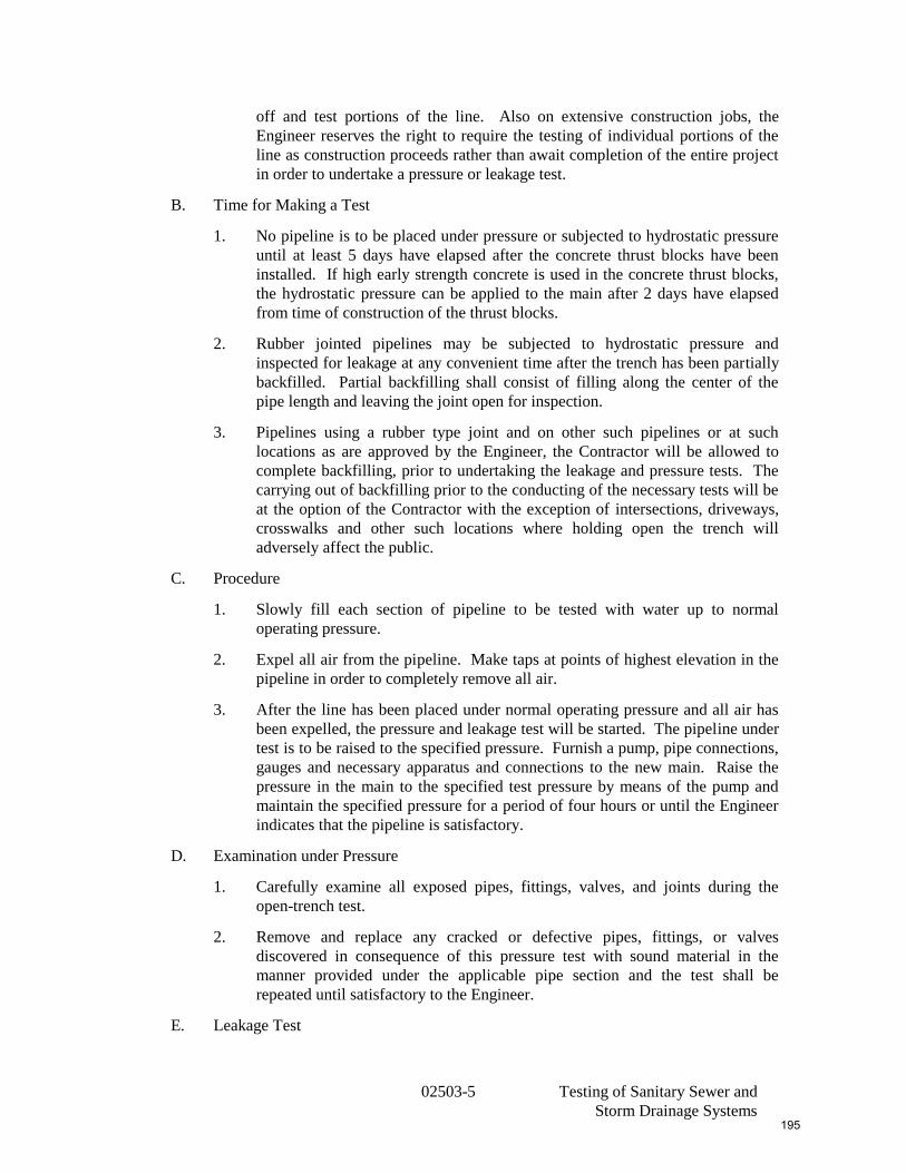
off and test portions of the line. Also on extensive construction jobs, the
Engineer reserves the right to require the testing of individual portions of the
line as construction proceeds rather than await completion of the entire project
in order to undertake a pressure or leakage test.
B. Time for Making a Test
1. No pipeline is to be placed under pressure or subjected to hydrostatic pressure
until at least 5 days have elapsed after the concrete thrust blocks have been
installed. If high early strength concrete is used in the concrete thrust blocks,
the hydrostatic pressure can be applied to the main after 2 days have elapsed
from time of construction of the thrust blocks.
2. Rubber jointed pipelines may be subjected to hydrostatic pressure and
inspected for leakage at any convenient time after the trench has been partially
backfilled. Partial backfilling shall consist of filling along the center of the
pipe length and leaving the joint open for inspection.
3. Pipelines using a rubber type joint and on other such pipelines or at such
locations as are approved by the Engineer, the Contractor will be allowed to
complete backfilling, prior to undertaking the leakage and pressure tests. The
carrying out of backfilling prior to the conducting of the necessary tests will be
at the option of the Contractor with the exception of intersections, driveways,
crosswalks and other such locations where holding open the trench will
adversely affect the public.
C. Procedure
1. Slowly fill each section of pipeline to be tested with water up to normal
operating pressure.
2. Expel all air from the pipeline. Make taps at points of highest elevation in the
pipeline in order to completely remove all air.
3. After the line has been placed under normal operating pressure and all air has
been expelled, the pressure and leakage test will be started. The pipeline under
test is to be raised to the specified pressure. Furnish a pump, pipe connections,
gauges and necessary apparatus and connections to the new main. Raise the
pressure in the main to the specified test pressure by means of the pump and
maintain the specified pressure for a period of four hours or until the Engineer
indicates that the pipeline is satisfactory.
D. Examination under Pressure
1. Carefully examine all exposed pipes, fittings, valves, and joints during the
open-trench test.
2. Remove and replace any cracked or defective pipes, fittings, or valves
discovered in consequence of this pressure test with sound material in the
manner provided under the applicable pipe section and the test shall be
repeated until satisfactory to the Engineer.
E. Leakage Test
195
02503-6 Testing of Sanitary Sewer and
Storm Drainage Systems
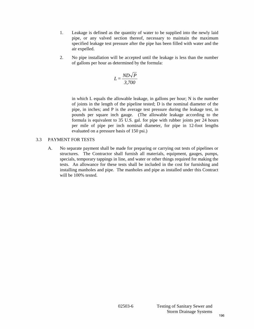
1. Leakage is defined as the quantity of water to be supplied into the newly laid
pipe, or any valved section thereof, necessary to maintain the maximum
specified leakage test pressure after the pipe has been filled with water and the
air expelled.
2. No pipe installation will be accepted until the leakage is less than the number
of gallons per hour as determined by the formula:
in which L equals the allowable leakage, in gallons per hour; N is the number
of joints in the length of the pipeline tested; D is the nominal diameter of the
pipe, in inches; and P is the average test pressure during the leakage test, in
pounds per square inch gauge. (The allowable leakage according to the
formula is equivalent to 35 U.S. gal. for pipe with rubber joints per 24 hours
per mile of pipe per inch nominal diameter, for pipe in 12-foot lengths
evaluated on a pressure basis of 150 psi.)
3.3 PAYMENT FOR TESTS
A. No separate payment shall be made for preparing or carrying out tests of pipelines or
structures. The Contractor shall furnish all materials, equipment, gauges, pumps,
specials, temporary tappings in line, and water or other things required for making the
tests. An allowance for these tests shall be included in the cost for furnishing and
installing manholes and pipe. The manholes and pipe as installed under this Contract
will be 100% tested.
3,700
PND=L
196
02503-7
TABLE I
SPECIFICATION TIME REQUIRED FOR A 1.0 PSIG PRESSURE DROP
FOR SIZE AND LENGTH OF PIPE INDICATED FOR Q=0.0015
1 Pipe Diameter
(in.)
2 Minimum
Time (min:sec)
3 Length for
Minimum Time (ft)
4 Time for
Longer Length (sec)
Specification Time for Length (L) Shown (min:sec)
100 ft. 150 ft. 200 ft. 250 ft. 300 ft. 350 ft. 400 ft. 450 ft.
4 3:46 597 .380 L 3:46 3:46 3:46 3:46 3:46 3:46 3:46 3:46
6 5:40 398 .854 L 5:40 5:40 5:40 5:40 5:40 5:40 5:42 6:24
8 7:34 298 1.520 L 7:34 7:34 7:34 7:34 7:36 8:52 10:08 11:24
10 9:26 239 2.374 L 9:26 9:26 9:26 9:53 11:52 13:51 15:49 17:48
12 11:20 199 3.418 L 11:20 11:20 11:24 14:15 17:05 19:56 22:47 25:38
15 14:10 159 5.342 L 14:10 14:10 17:48 22:15 26:42 31:09 35:36 40:04
18 17:00 133 7.692 L 17:00 19:13 25:38 32:03 38:27 44:52 51:16 57:41
21 19:50 114 10.470 L 19:50 26:10 34:54 43:37 52:21 61:00 69:48 78:31
24 22:40 99 13.674 L 22:47 34:11 45:34 56:58 68:22 79:46 91:10 102:33
27 25:30 88 17.306 L 28:51 43:16 57:41 72:07 86:32 100:57 115:22 129:48
30 28:20 80 21.366 L 35:37 53:25 71:13 89:02 106:50 124:38 142:26 160:15
33 31:10 72 25.852 L 43:05 64:38 86:10 107:43 129:16 150:43 172:21 193:53
36 34:00 66 30.768 L 51:17 76:55 102:34 128:12 153:50 179:29 205:07 230:46
Uni-Bell PVC Pipe Association Publication Uni-B-6-90
END OF SECTION
J:\L\L0175\SPEC-2004\02503.doc
197
02515-1 Polyvinyl Chloride (PVC) Pipe and Fittings
SECTION 02515
POLYVINYL CHLORIDE (PVC) PIPE AND FITTINGS
PART 1 GENERAL
1.1 SUMMARY
A. Section Includes
1. PVC Gravity Pipe and Fittings
2. PVC Pressure Pipe and Fittings
3. PVC Low Pressure Pipe and Fittings for grinder pump systems.
B. Related Sections
1. Section 02315 - Excavating, Backfilling and Compaction
2. Section 02317 – Underground warning Tape
3. Section 02320 - Borrow Material
4. Section 02503 – Testing of Sanitary Sewer and Storm Drainage Systems
1.2 REFERENCES
A. ASTM D2241 - Specification for Polyvinyl Chloride (PVC) Plastic Pipe (SDR-PR).
B. ASTM F477 - Specification for Elastomeric Seals (Gaskets) for Joining Plastic Pipe.
C. ASTM D3034 - Specification for Type PSM Polyvinyl Chloride (PVC) Sewer Pipe
and Fittings.
D. ASTM D2444 - Standard Test Method for Impact Resistance of Thermoplastic Pipe
and Fittings by Means of a Tup (Falling Weight).
E. ASTM D2412 - Standard Test Method for External Loading Properties of Plastic Pipe
by Parallel-Plate Loading.
F. ASTM D3139 - Standard Specifications for Joints for Plastic Pressure Pipes Using
Flexible Elastomeric Seals.
G. ASTM D3212 - Specification for Joints for Drain and Sewer Plastic Pipes Using
Flexible Elastomeric Seals.
H. ASTM F679 - Specification for Polyvinyl Chloride (PVC) Large-Diameter Plastic
Gravity Sewer Pipe and Fittings.
I. ASTM D1869 - Standard Specification for Rubber Rings for Asbestos-Cement Pipe.
J. AWWA A21 - Ductile Iron Pipe and Fittings.
K. AWWA C900 - Polyvinyl Chloride (PVC) Pressure Pipe, 4 in. through 12 in., For
Water Distribution.
1.3 SUBMITTALS
198
02515-2 Polyvinyl Chloride (PVC) Pipe and Fittings
A. Submit specifications and shop drawings for materials and equipment furnished under
this Section.
B. Prior to first shipment of pipe, submit certified test reports that the pipe for this
Contract was manufactured and tested in accordance with the ASTM Standards
specified herein.
1.4 QUALITY ASSURANCE
A. Each type of PVC pipe and fittings shall be from a single manufacturer.
B. Inspection of the pipe will also be made by the Owner after delivery. The pipe shall
be subject to rejection at any time on account of failure to meet any of the
Specification requirements. Pipe rejected after delivery shall be marked for
identification and shall immediately be removed from the job site.
PART 2 PRODUCTS
2.1 MATERIALS
A. Gravity Pipe
1. Polyvinyl chloride (PVC) pipe shall be of the size indicated on the Drawings or
as specified and shall conform to the latest revision of ASTM D3034, Type
SDR 35 for diameters less than or equal to 15-inch diameter and ASTM F679
for pipe greater than 15-inch diameter. Standard laying lengths shall not
exceed 13.0 feet for main line pipe and 6.5 feet for lateral pipe.
2. Joints shall be elastomeric gasket joints and shall provide a watertight seal.
Assembly of joints shall be in accordance with ASTM D3212.
3. The minimum "pipe stiffness" (load divided by change in inside diameter in
direction of load application) at 5% deflection shall be at least 46 psi for pipe
tested in accordance with ASTM D2412.
4. No shattering or splitting shall be evident when 150 ft.-lbs. and 210 ft.-lbs. is
impacted on 4-inch and 6-inch diameter pipe, respectively, in accordance with
ASTM Method of Test D2444.
5. Pipe lengths and fittings to be used on the project shall be clearly marked on
the outside in bold type with the name of the manufacturer, pipe size, pipe
material, pipe class, and ASTM designation.
6. Gravity Pipe House Connections
a. Gravity pipe house connections, wyes and tees are to be laid in the run
of the main pipeline, the wyes and tees shall be the same material as the
main line and shall conform in material, joints and class with the line
into which they are to be laid.
b. Eighth and sixteenth bends and end plugs are to be of the same material
and class or strength designation as the pipe for the house connection.
c. Unless noted on the Drawings, house service piping shall be 6-inch
diameter and shall be of the same material as the main line PVC pipe.
7. Lateral Chimneys
199
02515-3 Polyvinyl Chloride (PVC) Pipe and Fittings
a. Pipe and fittings shall be 6-inch diameter and be of the same material as
the main line PVC pipe.
b. Concrete used for construction of chimneys shall be 3,000 psi.
B. Pressure Pipe
1. Polyvinyl Chloride (PVC) pressure pipe shall be of the size indicated on the plans and shall conform to the requirements of the AWWA C900 Standards for PVC900 DR 18 Pressure Pipe for Water with cast iron pipe equivalent outside diameters. Joints shall use elastomeric gaskets and be in accordance with ASTM D3139. Gaskets shall conform to ASTM F477.
2. The standard laying length shall not exceed 20 feet. The minimum “pipe stiffness” (load divided by change in inside diameter in direction of load application) at 5% deflection shall be at least 46 psi for pipe tested in accordance with ASTM Specifications D2412.
3. Bends shall be constructed of cast iron or ductile iron in accordance with AWWA A21.10 and A21.53, with mechanical joint ends.
4. Pipe and fittings shall be clearly marked on the outside indicating the name of the manufacturer, nominal diameter, and the ASTM or AWWA designation or both for the DR18 Polyvinyl Chloride Pressure Pipe.
C. Low Pressure Pipe
1. Polyvinyl Chloride (PVC) pipe for low pressure sewers shall be of the same
size indicated on the Drawings and shall be PVC, Type 1120, ASTM 2241,
Class 200 (SDR-21). Joints shall use elastomeric gaskets conforming to
ASTM D1869. Connections to tees, brass fittings and end caps shall be made
using solvent welded joints.
2. The standard laying length shall not exceed 20 feet. Pipe and fittings shall be
clearly marked on the outside indicating the name of the manufacturer, ASTM
designation and the nominal diameter.
3. House Connections and Valves
a. Low pressure sewer connections from each sewage grinder pump station
shall be PVC, Type 1120, ASTM D2241, Class 200 (SDR-21). Joints
shall use elastomeric gaskets conforming to ASTM D1869. The piping
shall be connected to the 1¼ -inch pump station discharge fitting using a
1¼-inch to 1½-inch increaser.
b. The standard laying length shall not exceed 20 feet. Pipe and fittings
shall be clearly marked on the outside indicating the name of the
manufacturer, ASTM designation and the nominal diameter.
c. Bends used shall use elastrometric gaskets and shall have a poured in-
place or precast concrete thrust block bearing against undisturbed soil.
Bends shall be SDR-21, Class 200 and capable of withstanding pressure
surges.
d. Low pressure services shall connect to the gravity sewer using a
stainless steel saddle. An end cap, suitable for withstanding line test
200
02515-4 Polyvinyl Chloride (PVC) Pipe and Fittings
pressure shall be supplied and installed. A 2-inch x 4-inch marker pole
is to be installed at each service connection termination.
e. Curb stops shall be threaded bronze ball valves and shall open left. Curb
stops shall not be stop/waste-type. Valves shall be Red Head Model
B2230, Mueller, Ford or approved equal.
f. Each curb stop shall be provided with its own extension type cast iron 3-
inch road box and lid assembly. The lid shall have the word “sewer”
imprinted on it. Box extensions for deep installations shall also be
provided as required. A total of four (4) tee handle wrench operators
suitable to operate the curb stops installed shall be provided.
g. Each service connection shall have a check valve installed on the
upstream side of the curb stop. The check valve shall have a PVC body,
an internal flapper type suitable for direct burial and threaded
connections.
PART 3 EXECUTION
3.1 HANDLING PIPE AND FITTINGS
A. Take care in loading, transporting, and unloading to prevent injury to the pipe. Do not drop pipe or fittings. Examine pipe and fittings before installing, and no piece shall be installed which is found to be defective.
B. If any defective pipe is discovered after it has been installed, remove and replace it with a sound pipe in a satisfactory manner. Throughly clean pipe and fittings before installing, keep clean until they are used in the work, and conform to the lines, grades and dimensions required when installed.
C. Pipe ends requiring cutting shall be cut square without damage to the remaining pipe. Bevel cut pipe ends 1/8-inch at approximately 30 degrees to provide proper assembly of the joint. Beveling can be done with a coarse file or portable grinder.
D. Support stored pipe from below at not more than 3 ft. intervals to prevent deformation. Do not stack pipe higher than 6 ft. Store pipe and fittings in a manner which will keep them at ambient outdoor temperatures. Provide temporary shading as required to meet this requirement. Simply covering of the pipe and fittings which allows temperature buildup when exposed to direct sunlight will not be permitted.
3.2 INSTALLATION
A. No single piece of pipe shall be laid unless it is generally straight. The centerline of the pipe shall not deviate from a straight line drawn between the centers of the openings at the ends of the pipe by more than 1/16 inch per foot of length. If a piece of pipe fails to meet this requirement check for straightness, it shall be rejected and removed from the site. Laying instructions of the manufacturer shall be explicitly followed.
B. Install piping and fittings true to alignment and grade. If necessary, each length of pipe shall be cleaned out before installation.
C. Excavation, trenching and back filling procedures shall be in accordance with Section 02315.
D. All sections of pipe will be air tested in accordance with Section 02503.
201
02515-5 Polyvinyl Chloride (PVC) Pipe and Fittings
E. Dense graded stone bedding for the pipe shall be in accordance with Section 02320.
F. Install underground warning tape over pipe in accordance with Section 02317.
G. Install PVC pipe on a bed of dense graded stone with a minimum depth of 6-inches. The dense graded stone shall completely encase the pipe and cover the pipe to a grade 6-inches over the top of the pipe to a minimum width of 12-inches on each side of the pipe. Bell holes shall be made in a dense graded stone such that the pipe shall be uniformly supported throughout the entire length of the barrel section.
H. Deflections in Pipe Alignment.
1. Wherever it is necessary to deflect pipe from a straight line, either in the vertical or horizontal plane, to avoid obstructions or where long-radius curves are permitted, the amount of deflection allowed shall not exceed that required for satisfactory making of the joint, and shall be approved by the Engineer.
2. Prior to deflecting the pipeline, the spigot of the pipeline should be marked flush with the bell end to assure that the spigot is not withdrawn excessively as the result of the deflection. After the pipe is deflected, an adequate depth of jointing material must remain on the side where the spigot is away from home and an adequate width of caulking space must remain on the opposite side of the pipe at the face of the bell.
3. The maximum deflection recommended by the manufacturer when using any pipe system must be observed when deflecting a pipeline.
4. In general, all radius curves called for on the Drawings or permitted at the time of construction are to be made using full lengths of pipe. The use of short lengths of pipe and extra joint in order to make a smaller radius turn will not be allowed without the written approval of Engineer.
I. Unsuitable Laying Conditions
1. No pipe shall be laid in water, in an unsuitable trench or during unsuitable
weather conditions.
J. Chimney Construction Methods
1. Whenever indicated on the Contract Drawings or directed by the Engineer, the
Contractor shall install a house connection chimney. House connection
chimneys will be authorized by the Engineer only where the difference in
elevation between the main pipe invert and the house water table (sill) is at
least 13 feet and the main line pipe is at least 10 feet deep.
2. The Contractor shall carefully place the pipe and fittings forming the house
service chimneys in accordance with the standard detail for “House Connection
Chimney.” The pipe fittings shall be braced and supported as necessary to
ensure their staying in proper position while the concrete encasement is being
placed. Chimneys shall be constructed in such a manner that loads are not
transferred to the mainline.
202
02515-6 Polyvinyl Chloride (PVC) Pipe and Fittings
END OF SECTION
J:\L\L0175\SPEC-2004\02515.doc
203