Embed Size (px)
Citation preview
UNM Revised April 2018
FM Lockshop Page 1
SECTION 08110 – STEEL DOORS AND FRAMES
PART 1- GENERAL
1.1 RELATED DOCUMENTS
A. Drawing and general provisions of the Contract, including General and Supplementary Conditions and other Division 1 Specification Sections, apply to this Section.
1.2 SUMMARY
A. This section includes the following
1. Interior and exterior steel doors and frames
2. Interior 1” and 2” face dimension steel frames, including transoms, sidelights,
and clerestories and borrow lights.
3. Exterior steel doors and frames
B. Related Sections:
1. Division 4 Section “Unit Masonry Assemblies” for building anchors into and grout steel frames in masonry construction.
2. Division 8 Section “Glazing” for glazed lights in steel doors and frames.
3. Division 8 Section “Door Hardware” for hardware for steel doors and frames.
4. Division 9 Section “Gypsum Board Assemblies.”
5. Division 9 Section “Painting” for field painting steel doors and frames.
6. Division 13 Section “Radiation Protection” for lead-lined flush wood doors.
1.3 SUBMITTALS
A. Provide submittals in accordance with Division 1.
B. Product Data: Submit complete printed data, include door designation, type, level and
model, material and finish description, core description, construction details, and label compliance.
C. Shop Drawings: Details of each opening, showing elevation, glazing, frame profiles, and
identifying location of different finishes, if any.
D. Oversize Construction Certificates: Submit certification for door assemblies required to be fire-protection rated and exceeding size limitations of labeled assemblies.
E. Thermal Performance Certification: For exterior door assemblies, submit certification
UNM Revised April 2018
FM Lockshop Page 2
required under “Quality Assurance” of this specification.
1.4 QUALITY ASSURANCE
A. General: Comply with ANSI A 250.8, unless more stringent requirements are indicated.
B. Fire-Rated Door Assemblies: Provide assemblies complying with NFPA 80 that are listed and labeled by a testing and inspecting agency acceptable to authorities having jurisdiction, for fire-protection ratings indicated, based on testing according to NFPA 252. 1. Test Pressure: Test at atmospheric pressure. 2. Oversize Fire-Rated Door Assemblies: For units exceeding sizes of tested
assemblies provide certification by a testing agency acceptable to authorities having jurisdiction that doors comply with standard construction requirements for tested and labeled fire-rated door assemblies except for size.
3. Temperature-Rise Rating: Where indicated and where steel doors are shown in stairwells and exit enclosures, provide doors that have a temperature-rise rating of 450°° F (250 ° C) maximum in 30 minutes of fire exposure.
C. Fire-Rated Window Assemblies: Assemblies complying with NFPA 80 that are listed and
labeled by a testing and inspecting agency acceptable to authorities having jurisdiction, for fire ratings indicated, based on testing according to NFPA 257.
D. Thermal Performance: Provide exterior door assembly (door and frame) having a maximum
U-factor of 0.700 as determined in accordance with NFRC 100 by a laboratory accredited by a naturally recognized accreditation organization such as the National Fenestration Rating Council and labeled and certified by the manufacturer or if not as labeled certified y the manufacturer to have a maximum U-factor of 0.50.
1.5 DELIVERY, STORAGE, AND HANDLING
A. Deliver wrapped or crated to provide protection during transit and job storage.
B. Inspect on delivery for damage. Minor damages may be repaired, provided refinished items
match new work and are acceptable to Architect. Remove and replace damaged items that cannot be repaired as directed.
C. Store doors and frames at building site under cover. Place units on minimum 4-inch (100-
mm) high wood blocking. Avoid using non-vented plastic or canvas shelters that could create a humidity chamber. If packaging becomes wet, remove cartons immediately. Provide minimum ¼-inch (6mm) spaces between stacked doors to permit air circulation.
PART 2 – PRODUCTS
2.1 MANUFACTURERS
A. Regularly engaged in the manufacture of the type of units specified for a minimum of five
(5) years.
2.2 MATERIALS
A. Hot-Rolled Steel Sheets: ASTM A 569A 569M, Commercial Steel (CS), Type B; free of Scale, pitting, or surface defects: pickled and oiled.
UNM Revised April 2018
FM Lockshop Page 3
B. Cold-Rolled Steel Sheets: ASTM A 366/A 366M, Commercial Steel (CS), or ASTM A 620/A 620M, Drawing Steel (DS), Type B; stretcher-leveled standard of flatness.
C. Metallic-Coated Steel Sheets: ASTM A 653/A 653M, Commercial Steel (CS), Type B, with
an A40 (ZF120) zinc-iron-alloy (galvannealed) coating; stretcher-leveled standard of flatness.
D. Electrolytic Zinc-Coated Steel Sheet: ASTM A 591/A 591M, Commercial Steel (CS), Class
B coating; mill phosphatized; suitable for unexposed applications; stretcher-leveled standard of flatness where used for face sheets.
2.3 DOORS
A. Interior Doors: Complying with requirements indicated below by referencing ANSI 250.8
For level and model and ANSI A250.4 for physical-endurance level:
1. Level 2 and Physical Performance Level B (Heavy-Duty), Model 1 (Full Flush) (18 gauge) (0.042-inch) (1.0 MM).
B. Exterior Doors: Provide doors complying with requirements indicated below by referencing
ANSI A250.8 for level and model and ANSI A250.4 for physical-endurance level:
1. Level 3 and Physical Performance Level A (Extra Heavy-Duty), Model 2 (seamless) (16 gauge) (0.05 3-inch) (1.3 mm).
2.4 FRAMES
A. General: Comply with ANSI A250.8 and with details indicated for type and profile.
Conceal fastenings, unless otherwise indicated.
B. Interior Openings: Provide 0.053-inch- (1.3-mm-) (16 gauge) thick steel sheet.
C. Exterior Openings: Provide 0.067-inch (1.6-mm-) (14 gauge) thick steel sheet.
D. Door Silencers: Except on weather-stripped frames, fabricate stops to receive three silencers on strike jambs of single-door frames and two silencers on heads of double-door frames.
E. Guards: Provide 0.016-inch- (0.4-mm-) thick, steel sheet boxes to close of interior of
openings; place at back of hardware cutouts where mortar or other materials might obstruct hardware operation.
F. Supports and Anchors: Fabricated from not less than 0.042-inch- (1.0-mm-) thick,
electrolytic zinc-coated or metallic-coated steel sheet.
1. Wall Anchors in Masonry Construction: 0.177-inch-(4.5-mm-) diameter, steel wire complying with ASTM A 510 (ASTM A 510M) may be used in place of steel sheet.
G. Inserts, Bolts, and Fasteners: Manufacturer’s standard units. Where zinc-coated items are to
be built into exterior walls, comply with ASTM A 153/A 153M, Class C or D as applicable.
UNM Revised April 2018
FM Lockshop Page 4
2.5 FABRICATION
A. General: Fabricate units to comply with ANSI A250.8 and to be rigid, neat in appearance, and free from defects including warp and buckle. Where practical, fit and assemble units in manufacturer’s plant. Clearly identify work that cannot be permanently factory-assembled before shipment, to assure proper assembly at Project site.
B. Exterior Construction: Fabricate doors from metallic-coated steel sheet.
1. Close top and bottom edges of doors flush as an integral part of door construction or
by addition of 0.053-inch-(1.3-mm-) thick, metallic-coated steel channels with channel webs placed even with top and bottom edges.
C. Interior Door Faces: Fabricate exposed faces of doors and panels from cold-rolled steel
sheet.
D. Core Construction: Manufacturer’s standard core construction that produces a door complying with SDI standards.
1. Polyurethane or polystyrene at exterior.
E. Clearances for Non-Fire-Rated Doors: Not more than 1/8 inch (3.2 mm) at jambs and heads,
except not more than 1/4 inch (6.4 mm) between pairs of doors. Not more than 3/4 inch (19 mm) at bottom.
F. Clearances for Fire-Rated Doors: As required by NFPA 80.
G. Single Acting, Door-Edge Profile: Beveled edge lock jamb minimum.
H. Tolerances: Comply with SD1 117 “Manufacturing Tolerances for Standard Steel Doors
and Frames.”
I. Fabricate concealed stiffeners, reinforcement, edge channels, and moldings from either cold- or hot-rolled steel sheets.
J. Exposed Fasteners: Provide countersunk flat or oval heads for exposed screws and bolts.
K. Hardware Preparation: Prepare units to receive mortised and concealed hardware according
to final door hardware scheduled and templates provided by hardware supplier. Comply with applicable requirements in ANSI A250.6 and ANSI A115 Series specifications for door and frame preparation for hardware.
L. Frame Construction: Fabricate frames to shape shown.
1. Fabricate frames with mitered or coped and continuously welded corners and
seamless face joints, unless otherwise indicated.
2. Provide welded frames with temporary spreader bars.
M. Reinforce units to receive surface-applied hardware. Drilling and tapping for surface- applied hardware may be done at Project site. 1. Minimum thickness and size for hinge and pivot reinforcement: 7 gauge, 1 ¼” x
10”.
UNM Revised April 2018
FM Lockshop Page 5
2. Minimum thickness reinforcements for of Strike, flush bolt, closer, and surface mounted hardware: min. 12 gauge
N. Locate hardware as indicated in Section 08710 – Door Hardware.
O. Glazing Stops: Manufacturer’s standard, formed from 0.032-inch- (0.8-mm-) thick steel
sheet matching unit material.
1. Provide non-removable stops on outside of exterior doors and on secure side of interior doors for glass, louvers, and other panels in doors.
2. Provide screw-applied, removable, glazing stops on inside of glass, louvers, and
other panels in doors. P. Astragals: As required by NFPA 80 to provide fire ratings indicated.
2.6 FINISHES
A. Prime Finish: Manufacturer’s standard, factory-applied coat of rust-inhibiting primer
complying with ANSI A250.10 for acceptance criteria.
PART 3 – EXECUTION
3.1 INSTALLATION
A. General: Install according to Shop Drawings, manufacturer’s data, and as specified.
B. Placing Frames: Comply with provisions in SDI 105, and as specified. Set frames accurately in position, plumbed, aligned, and braced securely until permanent anchors are set. After wall construction is completed, remove temporary braces and spreaders, leaving surfaces smooth and undamaged.
1. In masonry construction, provide at least three wall anchors per jamb; install
adjacent to hinge location on hinge jamb and at corresponding heights on strike jamb.
2. In stud partitions, provide at least three wall anchors per jamb; install adjacent to
hinge location on hinge jamb and at corresponding heights on strike jamb. Attach wall anchors to studs with screws.
3. Install fire-rated frames according to NFPA 80.
4. For opening 90 inches (2286 mm) or more in height, install an additional anchor at
hinge and strike jambs.
C. Door Installation: Comply with ANSI A250.8. Fit hollow-metal doors accurately in frames, within clearances specified in ANSI A250.8. Shim as necessary to comply with SDI 122 and ANSI/DHI A115.1G.
1. Fire-Rated Doors: Install within clearances specified in NFPA 80.
2. Smoke-Control Doors: Install to comply with NFPA 105.
FM Lockshop Page 6
UNM Revised April 2018
3.2 ADJUSTING AND CLEANING
A. Prime-Coat Touchup: Immediately after installation, sand smooth any rusted or damaged areas of prime coat and apply touch up of compatible air-drying primer.
B. Protection Removal: Immediately before final inspection, remove protective wrappings
from doors and frames.
END OF SECTION 08110
SECTION 08211-WOOD DOORS
PART 1- GENERAL
1.1 RELATED DOCUMENTS
A. Drawing and general provisions of the Contract, including General and Supplementary Conditions and Division 1 Specification Sections, apply to this Section.
1.2 SUMMARY
A. This Section includes the following:
1. Solid-core doors with wood-veneer faces.
2. Factory finishing flush wood doors.
3. Factory-fitted flush wood doors to frames and factory machining for hardware.
4. Interior wood gliding doors.
5. Oversize interior wood doors.
6. Interior Solid Core Wood Door Transoms.
A. Related Sections including the following:
1. Division 8 Section 8110 “Steel Doors and Frames” for metal door frames for flush
wood doors.
2. Division 8 Section “Door Hardware” for hardware for flush wood doors.
3. Division 13 Section “Radiation Protection” for lead-lined flush wood doors.
1.3 SUBMITTALS
A. Product Data: For each type of door. Include details for core and edge construction and trim for openings. Include factory-finishing specifications.
FM Lockshop Page 7
UNM Revised April 2018
B. Shop Drawings: Indicate location, size, and hand of each door; elevation of each kind of door; construction details not covered in Product Data; location and extent of hardware blocking; and other pertinent data.
C. Samples for Verification:
1. Factory finishes applied to actual door face materials, approximately 8 by 10
inches (203 by 254 mm), for each material and finish. For each wood species and transparent finish, provide set of three (3) samples showing typical range of color and grain to be expected in the finished work.
2. Corner sections of doors, approximately 8 by 10 inches (203 by 254 mm), with
door faces and edgings representing typical and range of color and grain for each species of veneer and solid lumber required. Finish sample with same materials proposed for factory-finished doors.
3. Frames for light openings, 6 inches (152 mm) long, for each material, type, and finish required.
1.4 QUALITY ASSURANCE
A. Source Limitations: Obtain flush wood doors through one source from a single
Manufacturer
B. Quality Standard: Comply with NWWDA I.S. 1-A, “Architectural Wood Flush Doors.”
1. Provide AWI Quality Certification Labels or an AWI letter of licensing for Project indicating that doors comply with requirements of grades specified.
C. Fire-Rated Wood Doors: Doors complying with NFPA 80 that are listed and labeled by
a testing and inspecting agency acceptable to authorities having jurisdiction, for fire ratings indicated, based on testing according to UBC Standard 7-2.
D. Pre-installation Conference: Conduct conference at Project site to comply with
requirements in Division 1.
1.5 DELIVERY, STORAGE, AND HANDLING
A. Comply with requirements of referenced standard and manufacturer’s written instructions.
B. Package doors individually in plastic bags or cardboard cartons.
C. Mark each door on top and bottom rail with opening number used on Shop Drawings.
D. Store doors and frames at building site under cover. Place units on minimum 4-inch (100-
mm) high wood blocking. Avoid using non-vented plastic or canvas shelters that could create a humidity chamber. If packaging becomes wet, remove cartons immediately. Provide minimum ¼-inch (6mm) spaces between stacked doors to permit air circulation.
1.6 PROJECT CONDITIONS
A. Environmental Limitations: Do not deliver or install doors until building is enclosed,
wet work is complete, and HVAC system is operating and will maintain temperature
FM Lockshop Page 8
UNM Revised April 2018
and relative humidity at occupancy levels during the remainder of the construction period.
PART 2 – PRODUCTS
2.1 MANUFACTURERS
A. Manufacturers: Subject to compliance with requirements, provide products by one of
the following:
1. Flush Wood Doors: a. Algoma Hardwoods Inc. b. Marshfield, Inc. c. Eggers Industries; Architectural Door Division.
2.2 DOOR CONSTRUCTION, GENERAL
A. Adhesives: Do not use adhesives containing urea formaldehyde.
B. Interior Doors for Transparent Finish:
1. Faces: Rotary cut Maple, or as specified and approved by Owner.
2. Pair and Set Match: Provide for doors hung in same opening or separated only by
mullions.
3. Room Match: Match door faces within each separate room or area of building. Corridor door faces do not need to match where they are separated by 20 feet (6m) or more.
4. Transom Match: End match.
5. Select doors have faces from the same veneer flitch to extent possible. Where
necessary, select doors having faces from veneer flitches similar in color and grade to other flitches to obtain continuity of door appearances throughout the project.
6. Stiles: Same species as faces or a compatible species or applied wood-veneer
edges of same species as faces and covering edges of faces.
2.3 SOLID-CORE DOORS
A. Interior Solid-Core Doors and Wood Door transoms:
1. Doors typically will be 1-3/4 inches (44.4 mm) thick, interior flush wood bonded solid core doors conforming to AWI standards for applications and ratings required.
2. Core: Particleboard or glued block.
3. Construction: Five plies.
4. Provide Type-2 door construction with Type-1 waterproof adhesive.
FM Lockshop Page 9
UNM Revised April 2018
5. Provide flush wood frames with manufacturers tested metal clip for wood stop.
6. Reinforcement for hardware to be 5-inch hardwood at closers and 10-inch hardwood at exit hardware.
B. Fire-Rated Doors
1. Construction: Construction and core specified above for type of face indicated or
manufacturer’s standard mineral-core construction as needed to provide fire rating indicated.
2. Pairs: Provide fire-rated pairs with fire-retardant stiles matching face veneer that are labeled and listed for kinds of applications indicated without formed-steel edges and astragals. Provide stiles with concealed intumescent seals.
3. Fire ratings for wood doors to include, no rating, 20 minute, 45 minute, 1-1//2 hour. Fire doors to be FD Core Component for hourly rating.
4. Provide slim-line metal trim where trim is required at fire rated doors.
2.4 LIGHT FRAMES
A. Wood Beads for Light Openings in Wood Doors:
1. Wood Species: Species compatible with door faces.
2. Profile: Manufacturer’s standard shape.
3. A 20-minute, fire-rated, wood-core door provides wood beads and metal glazing clips approved for such use.
B. Wood-Veneered Beads for Light Openings in Fire Doors: Manufacturer’s standard
wood-veneered noncombustible beads matching veneer species of door faces and approved for use in doors of fire rating indicated. Include concealed metal glazing clips where required for opening size and fire rating indicated.
C. Glazing: 1/4 inch (6 mm) tempered glass.
2.5 FABRICATION
A. Fabricate doors in sizes indicated for Project-site fitting.
B. Factory fit doors to suit frame-opening sizes indicated, with the following uniform clearances and bevels, unless otherwise indicated:
1. Comply with clearance requirements of reference quality standard for fitting.
2. Comply with requirements in NFPA 80 for fire-rated doors.
C. Factory machine doors for hardware that is not surface applied. Locate hardware to
comply with DHI-WDHS-3. Comply with final hardware schedules, door frame Shop Drawings, DHI A115-W series standards, and hardware templates.
UNM Revised April 2018
FMLockshop Page
1. Coordinate measurements of hardware mortises in metal frames to verify dimensions and alignment before factory machining.
2. Metal Astragals: Pre-machine astragals and formed-steel edges for hardware for
pairs of fire-rated doors.
D. Openings: Cut and trim openings through doors to comply with applicable Requirements of referenced standards for kind(s) of door(s) required.
1. Light Openings: Trim openings with moldings of material and profile indicated.
2.6 FACTORY FINISHING
A. General: Comply with AWI’s “Architectural Woodwork Quality Standards Illustrated”
for factory finishing.
B. Finish doors at factory.
C. Transparent Finish:
1. Grade: Premium. 2. Finish: Satin, medium rubbed, transparent, conversion varnish alkyd-urea. 3. Staining: Match Owner’s sample selected from manufacturer’s standard stains
and finishes.
PART 3 – EXECUTION
3.1 EXAMINATION
A. Examine doors and installed doorframes before hanging doors.
1. Verify that frames comply with indicated requirements for type, size, location, and swing characteristics and have been installed with level heads and plumb jambs.
2. Reject doors with defects.
B. Proceed with installation only after unsatisfactory conditions have been corrected.
3.2 INSTALLATION
A. Hardware: For installation, see Division 8 Section “Door Hardware.”
B. Manufacturer’s Written Instructions: Install doors to comply with manufacturer’s
written instructions, referenced quality standard, and as indicated.
1. Install fire-rated doors in corresponding fire-rated frames according to NFPA 80.
C. Factory-Fitted Doors: Align in frames for uniform clearance at each edge.
D. Factory-Finished Doors: Restore finish before installation if fitting or machining is required at Project site.
UNM Revised April 2018
FMLockshop Page
3.3 ADJUSTING
A. Operation: Rehang or replace doors that do not swing or operate freely.
B. Finished Doors: Replace doors that are damaged or do not comply with requirements. Doors may be repaired or refinished if work complies with requirements and shows no evidence of repair or refinishing.
END OF SECTION 08211
SECTION 08411 - ALUMINUM-FRAMED ENTRANCES AND STOREFRONTS
PART 1 - GENERAL
1.1 RELATED DOCUMENT
A. Drawings and general provisions of the Contract, including General and Supplementary Conditions and Division 1 Specification Sections, apply to this Section.
1.2 SUMMARY
A. This Section includes the following:
1. Exterior aluminum-framed storefronts.
a. Glazing is retained mechanically with gaskets on four sides.
2. Exterior manual-swing glazed aluminum doors.
B. Related Sections include the following:
1. Division 7 Section “Joint Sealants” for installation for joint sealants installed with aluminum-framed systems and for sealants to the extent not specified in this section.
2. Division 8 Section “Sliding Automatic Entrance Doors” for automatic entrances. 3. Division 8 Section “Door Hardware” for hardware to the extent not specified in this
section. 4. Division 8 Section “Exterior Glazing” for glazing in entrances and storefront framing. 5. Division 8 Section “Structural Sealant-Glazed Aluminum Curtain Walls.
1.3 PERFORMANCE REQUIREMENTS
A. General: Provide aluminum-framed systems, including anchorage, capable of withstanding,
without failure, the effects of the following:
1. Structural loads. 2. Thermal movements. 3. Movements of supporting structure indicated on Drawings including, but not limited to,
story drift and deflection from uniformly distributed and concentrated live loads. 4. Dimensional tolerances of building frame and other adjacent construction.
UNM Revised April 2018
FMLockshop Page
5. Failure includes the following:
a. Deflection exceeding specified limits. b. Thermal stresses transferred to building structure. c. Framing members transferring stresses, including those caused by thermal and
structural movements, to glazing. d. Glazing-to-glazing contact. e. Noise or vibration created by wind and thermal and structural movements. f. Loosening or weakening of fasteners, attachments, and other components. g. Sealant failure. h. Failure of operating units to function properly.
B. Structural Sealant: Capable of withstanding tensile and shear stresses imposed by aluminum-
framed systems without failing adhesively or cohesively. Provide sealant that fails cohesively before sealant releases from substrate when tested for adhesive compatibility with each substrate and joint condition required.
1. Adhesive failure occurs when sealant pulls away from substrate cleanly, leaving no
sealant material behind. 2. Cohesive failure occurs when sealant breaks or tears within itself but does not separate
from each substrate because sealant-to-substrate bond strength exceeds sealant’s internal strength.
C. Structural-Sealant Joints: Designed to produce tensile or shear stress in structural-sealant joints
of less than 20 psi.
D. Deflection of Framing Members:
1. Deflection Normal to Wall Plane: Limited to 1/175 of clear span for spans up to 13 feet 6 inches or an amount that restricts edge deflection of individual glazing lite to 3/4 inch,
2. Deflection Parallel to Glazing Plane; Limited to 1/360 of clear span or 1/8 inch, whichever is smaller.
E. Structural-Test Performance: Provide aluminum-framed systems tested according to
ASTTM E 330 as follows:
1. When Tested at positive and negative wind-load design pressures, systems do not evidence deflection exceeding specified limits.
2. When tested at 150 percent of positive and negative wind-load design pressures, systems, including anchorage, do not evidence material failures, structural distress, and permanent deformation of main framing members exceeding 0.2 percent of span.
3. Test Durations: As required by design wind velocity but not less than 10 seconds.
F. Windborne-Debris-Impact-Resistance-Test Performance: Provide aluminum-framed systems that pass large and small missile-impact tests and cyclic-pressure test.
G. Thermal Movements: Provide aluminum-framed systems that allow for thermal movements
resulting from the following maximum change (range) in ambient and surface temperatures. Base engineering calculation on surface temperatures of materials due to both solar heat gains and nighttime-sky heat loss.
1. Temperature Change (Range): 120 deg F., ambient; 180 deg F., material surfaces. 2. Test Performance: No buckling; stress on glass; sealant failure; excess stress on framing,
UNM Revised April 2018
FMLockshop Page
Anchors, and fasteners; or reduction of performance when tested according to AAMA 501.5.
H. Air Infiltration: Provide aluminum-framed systems with maximum air leaking through fixed
glazing and framing areas of 0.06 cfm/sq. ft. of fixed wall area when tested according to ASTM E 283 at a minimum static-air-pressure difference of 6.24 lbf/sq. ft.
I. Water Penetration Under Static Pressure: Provide aluminum-framed systems that do not
evidence water penetration through fixed glazing and framing areas when tested according to ASTM E 331 at a minimum static-air-pressure difference of 20 percent of positive wind-load design pressure, but not less than 6.24 lbf. /sq. ft.
J. Water Penetration Under Dynamic Pressure: Provide aluminum-framed systems that do not
Evidence water leakage through fixed glazing and framing areas when tested according to AAMA 501.1 under dynamic pressure equal to 20 percent of positive wind-load design pressure, but not less than 6.24 lbf/sq. ft.
1. Maximum Water Leakage: No uncontrolled water penetrating systems or appearing on
systems’ normally exposed interior surfaces from sources other than condensation. Water controlled by flashing and gutters that is drained to exterior and cannot damage adjacent materials or finishes is not considered water leakage.
K. Condensation Resistance: Provide aluminum-framed systems with fixed glazing and framing
areas having condensation-resistance factor (CRF) of not less than 53 when tested according to AAMA 1503.
L. Average Thermal Conductance: Provide aluminum-framed systems with fixed glazing and
framing areas having average U-factor of not more than 0.69 Btu/sq. ft. x h x deg. when tested according to AAMA 1503.
M. Sound Transmission: Provide aluminum-framed systems with fixed glazing and framing area
having minimum STC 32 according to ASTM E 413 and an OITC 26 according to ASTM E 1332, as determined by testing according to ASTM E 90.
1.4 SUBMITTALS
A. Product Data: Include construction details, material descriptions, dimensions of individual Components and profiles, and finishes for each type of product indicated.
B. Shop Drawings: For aluminum-framed systems. Include plans, elevations, sections, details,
and attachments to other work.
1. Include structural analysis data signed and sealed by the qualified professional engineer responsible for their preparation.
2. Include details of provisions for system expansion and contraction and for draining moisture occurring within the system to the exterior.
3. For entrances, include hardware schedule and indicate operating hardware types, functions, quantities, and locations.
C. Samples for Verification: For each type of exposed finish required, in manufacturer’s standard
sizes.
UNM Revised April 2018
FMLockshop Page
D. Fabrication Sample: Of each vertical-to-horizontal intersection of systems, made from 12-inch Lengths of full-size components and showing details of the following:
1. Joinery. 2. Anchorage. 3. Expansion provisions. 4. Glazing. 5. Flashing and drainage.
E. Welding certificates. F. G. Qualification Data: For Installer.
H. Preconstruction Sealant Test Reports: For structural-sealant-glazed systems, compatibility and
adhesion test reports from sealant manufacturer indicating that materials forming joint substrates and joint-sealant backings have been tested for compatibility and adhesion with sealants. Include sealant manufacturer’s interpretation of test results for sealant performance and recommendations for primers and substrate preparation needed to obtain adhesion.
I. Product Test Reports: Based on evaluation of comprehensive tests performed by a qualified
testing agency, for aluminum-framed systems.
J. Field quality-control test and inspection reports.
K. Maintenance Data: For aluminum-framed systems to include in maintenance manuals.
L. Warranties: Special warranties specified in this Section.
1.5 QUALITY ASSURANCE
A. Installer Qualifications: Capable of assuming engineering responsibility and performing work of this Section and who is acceptable to manufacturer.
1. Engineering Responsibility: Preparation of data for aluminum-framed systems including
Shop drawings based on testing and engineering analysis of manufacturer’s standard units in assemblies similar to those indicated for this Project and submission of reports of tests performed on manufacturer’s standard assemblies.
B. Testing Agency Qualifications: An independent agency qualified according to ASTM E 699 for
testing indicated.
C. Product Options: Information on Drawings and in Specifications establishes requirements for systems’ aesthetic effects and performance characteristics. Aesthetic effects are indicated by dimensions, arrangements, alignment, and profiles of components and assemblies as they relate to sightlines, to one another, and to adjoining construction. Performance characteristics are indicated by criteria subject to verification by one or more methods including preconstruction testing, field testing, and in-service performance.
1. Do not modify intended aesthetic effects, as judged solely by Owner, except with
UNM Revised April 2018
FMLockshop Page
Owner’s approval. IF modifications are proposed, submit comprehensive explanatory ata to Owner for review.
D. Accessible Entrances: Comply with ADA and ANSI A117.1.
E. Welding: Qualify procedures and personnel according to AWS D1.2, “Structural Welding Code-Aluminum.”
F. Structural-Sealant Glazing: Comply with recommendations in ASTM C 1401, “Guide for
Structural Sealant Glazing.”
G. Structural-Sealant Joints: Design reviewed and approved by structural-sealant manufacturer.
H. Mockups: Build mockups to demonstrate aesthetic effects and set quality standards for fabrication and installation.
1. Build mockup of typical wall area as shown on Drawings. 2. Approved mockups may become part of the completed Work if undisturbed at time of
Substantial Completion.
1.6 PROJECT CONDITIONS
A. Field Measurements: Verify actual locations of structural supports of aluminum-framed systems by field measurements before fabrication and indicate measurements on Shop Drawings.
1. Established Dimensions: Where field measurements cannot be made without delaying
the Work, establish dimensions and proceed with fabricating aluminum-framed systems without field measurements. Coordinate construction to ensure that actual dimensions correspond to established dimensions.
1.7 WARRANTY
A. Special Assembly Warranty: Manufacturer’s standard form in which manufacturer agrees to repair or replace components of aluminum-framed systems that do not comply with requirements or that deteriorates as defined in this Section within specified warranty period.
1. Failures include, but are not limited to, the following:
a. Structural failures including, but not limited to, excessive deflection. b. Noise or vibration caused by thermal movements. c. Deterioration of metal and other materials beyond normal weathering. d. Adhesive or cohesive sealant failures. e. Water leakage through fixed glazing and framing areas. f. Failure of operating components to function properly.
2. Warranty Period: 10 years from date of Substantial Completion.
B. Special Finish Warranty: Manufacturer’s standard form in which manufacturer agrees to repair
or replace components on which finishes fail within specified warranty period. Warranty does
UNM Revised April 2018
FMLockshop Page
not include normal weathering.
1. Warranty Period: 20 years from date of Substantial Completion.
PART 2 – PRODUCTS
2.1 MANUFACTURERS
A. Basis of Design Product The design for aluminum-framed entrances and storefront is based on Tubelite Inc. Subject to compliance with requirements, provide the named product or a comparable product by one of the following: 1. Kawneer. 2. Pittco Architectural Metals, Inc. 3. EFCO Corporation.
2.2 MATERIALS
A. Aluminum: Alloy and temper recommended by manufacturer for type of use and finish
indicated.
1. Sheet and Plate: ASTM B 209.. 2. Extruded Bars, Rods, Profiles, and Tubes: ASTM B 221.. 3. Extruded Structural Pipe and Tubes: ASTM B 429. 4. Structural Profiles: ASTM B 308/B 308M. 5. Welding Rods and Bare Electrodes: AWS A5.10/A5.10M.
B. Steel Reinforcement: With manufacturer’s standard corrosion-resistant primer complying with
SSPC-PS Guide No. 12.00 applied immediately after surface preparation and pretreatment. Select surface preparation methods according to recommendations in SSPC-SP COM and prepare surfaces according to applicable SSPC standard.
1. Structural Shapes, Plates, and Bars: ASTM A 36/A 36M. 2. Cold-Rolled Sheet and Strip: ASTM A 1008/A 1008M. 3. Hot-Rolled Sheet and Strip: ASTM A 1011/A 1011M.
2.3 FRAMING SYSTEMS
A. Framing Members: Manufacturer’s standard extruded-aluminum framing members of thickness Required and reinforced as required to support imposed loads.
1. Construction: High-performance plastic connectors separate framing members exposed to
the exterior from members exposed to the interior.
B. Brackets and Reinforcements: Manufacturer’s standard high-strength aluminum with Non-staining, non-ferrous shims for aligning systems components.
C. Fasteners and Accessories: Manufacturer’s standard corrosion-resistant, non-staining,
Non-bleeding fasteners and accessories compatible with adjacent materials.
1. Where fasteners are subject to loosening or turning out from thermal and structural
UNM Revised April 2018
FMLockshop Page
Movements, wind loads, or vibration, use self-locking devices. 2. Reinforce members as required to receive fastener threads. 3. Use exposed fasteners with countersunk Phillips screw heads, finished to match framing
system.
D. Concrete and Masonry Inserts: Hot-dip galvanized cast-iron, malleable-iron, or steel inserts complying with ASTM A 123/A 123M or ASTM A 153/A 153M requirements.
E. Flashing: Manufacturer’s standard corrosion-resistant, non-staining, non-bleeding flashing
compatible with adjacent materials. Form exposed flashing from sheet aluminum finished to match framing and of sufficient thickness to maintain a flat appearance without visible deflection.
F. Framing System Gaskets and Sealants: Manufacturer’s standard recommended by manufacturer for joint type.
2.4 GLAZING SYSTEMS
A. Glazing: As specified in Division 8 Sections “Exterior Glazing” and “Interior Glazing”.
B. Glazing Gaskets: Manufacturer’s standard compression types, replaceable, molded or extruded, that maintain uniform pressure and watertight seal.
C. Spacers and Setting Blocks: Manufacturer’s standard elastomeric types.
D. Bond-Breaker Tape: Manufacturer’s standard TFFE-fluorocarbon or polyethylene material to
which sealants will not develop adhesion.
E. Glazing Sealants: For structural-sealant-glazed systems, as recommended by manufacturer for Joint type and as follows:
1. Structural Sealant: ASTM C 1184, neutral-curing silicone formulation compatible with
system components with which it comes in contact, specifically formulated and tested for use as structural sealant, and approved by structural-sealant manufacturer for use in aluminum-framed systems indicated.
a. Color: As selected by Architect from manufacturer’s full range of colors.
2. Weatherseal Sealant: ASTM C 920 for Type S, Grade NS, Class 25, Uses NT, G,A, and
O; neutral-curing silicone formulation compatible with structural sealant and other system components with which it comes in contact; and recommended by structural- and weatherseal-sealant and aluminum-framed system manufacturers for this use.
a. Color: Matching structural sealant.
2.5 DOORS
A. Doors: Manufacturer’s standard glazed doors, for manual swing operation.
1. Door Construction: 1-3/4-inch overall thickness, with minimum 0.125-inch- thick,
extruded-aluminum tubular rail and stile members. Mechanically fasten corners with reinforcing brackets that are deep penetration and fillet welded or that incorporate concealed tie rods.
UNM Revised April 2018
FMLockshop Page
2. Door Design: Wide stile; 5 inch nominal width.
a. Accessible Doors: Smooth surfaced for width of door in area within 12 inches
3. Glazing Stops and Gaskets: Square, snap-on, extruded-aluminum stops and preformed gaskets.
a. Provide non-removable glazing stops on outside of door.
B. Door Hardware: As specified in Division 8 Section “Door Hardware.”
2.6 ACCESSORY MATERIALS
A. Insulating Materials: As specified in Division 7 Section “Building Insulation.”
B. Joint Sealants: For installation at perimeter of aluminum-framed systems, as specified in
Division 7 Section “Join Sealants.”
C. Bituminous Paint: Cold-applied asphalt-mastic paint complying with SSPC-Paint 12 requirements except containing no asbestos, formulated for 30-mil thickness per coat.
2.7 FABRICATION
A. Form aluminum shapes before finishing.
B. Weld in concealed locations to greatest extent possible to minimize distortion or discoloration of finish. Remove weld spatter and welding oxides from exposed surfaces buy descaling or grinding.
C. Framing Members, General: Fabricate components that, when assembled, have the following
Characteristics:
1. Profiles that are sharp, straight, and free of defects or deformations. 2. Accurately fitted joints with ends coped or mitered. 3. Means to drain water passing joints, condensation occurring within framing members,
and moisture migrating within the system to exterior. 4. Physical and thermal isolation of glazing from framing members. 5. Accommodations for thermal and mechanical movements of glazing and framing to
maintain required glazing edge clearances. 6. Provisions for field replacement of glazing from exterior. 7. Fasteners, anchors, and connection devices that are concealed from view to greatest
extent possible.
D. Mechanically Glazed Framing Members: Fabricate for flush glazing (without projecting stops).
E. Structural-Sealant-Glazed Framing members: Include accommodations for using temporary support device (dutchman) to retain glazing in place while structural sealant cures.
F. Storefront Framing: Fabricate components for assembly using shear-block system.
G. Door Frames: Reinforce as required to support loads imposed by door operation and for
UNM Revised April 2018
FMLockshop Page
installing hardware.
1. At exterior doors, provide compression weather stripping at fixed stops.
H. Doors: Reinforce doors as required for installing hardware.
1. At pairs of exterior doors, provide sliding weather stripping retained in adjustable strip mortised into door edge.
2. At exterior doors, provide weather sweeps applied to door bottoms.
I. Hardware Installation: Factory installed hardware to the greatest extent possible. Cut, drill, and Tap for factory-installed hardware before applying finishes.
J. After fabrication, clearly mark components to identify their locations in Project according to
Shop Drawings.
2.8 ALUMINUM FINISHES
A. General: Comply with NAAMM’s “Metal Finishes Manual for Architectural and Metal Products” for recommendations for applying and designating finishes.
B. Finish designations prefixed by AA comply with the system established by the Aluminum
Association for designating aluminum finishes.
C. High-Performance Organic Finish (3-coat Fluoropolymer): AA-C12C40R1x (Chemical Finish: cleaned with inhibited chemicals; Chemical Finish: conversion coating; Organic Coating: manufacturer’s standard 3-coat, thermocured system consisting of specially formulated inhibitive primer and fluoropolymer colorcoat, and clear fluoropolymer topcoat, with both color coat and clear topcoat containing not less than 70 percent polyvinylidene fluoride rein by weight). Prepare, pretreat, and apply coating to exposed metal surfaces to comply with AAMA 2605 and with coating and manufacturer’s written instructions.
1. Color and Gloss: As selected by Architect from manufacturer’s full range.
2.9 SOURCE WUALITY CONTROL
A. Structural-Sealant-Glazed Systems: Perform quality-control procedures complying with ASTM C 1401 recommendations including, but not limited to, system material qualification procedures, sealant testing, and system fabrication reviews and checks
PART 3 – EXECUTION
3.1 EXAMINATION
A. Examine areas, with Installer present, for compliance with requirements for installation tolerances and other conditions affecting performance of work.
1. Proceed with installation only after unsatisfactory conditions have been corrected.
UNM Revised April 2018
FMLockshop Page
3.2 INSTALLATION
A. General:
1. Comply with manufacturer’s written instructions. 2. Do not install damaged components. 3. Fit joints to produce hairline joints free of burrs and distortion. 4. Rigidly secure non-movement joints. 5. Install anchors with separators and isolators to prevent metal corrosion and electrolytic
Deterioration 6. Seat joints watertight, unless otherwise indicated.
B. Metal Protection:
1. Where aluminum will contact dissimilar metals, protect against galvanic action by
painting contact surfaces with primer or by applying sealant or tape or installing nonconductive spacers as recommended by manufacturer for this purpose.
2. Where aluminum will contact concrete or masonry, protect against corrosion by painting contact surfaces with bituminous paint.
C. Install components to drain water passing joints, condensation occurring within framing
members, and moisture migrating within the system to exterior.
D. Set continuous sill members and flashing in full sealant bed as specified in Division 7 Section “Joint Sealants” and to produce weather tight installation.
E. Install components plumb and true in alignment with established lines and grades, without warp
or rack.
F. Install glazing as specified in Division 8 Sections “Exterior Glazing” and “interior Glazing”.
1. Structural-Sealant Glazing:
a. Prepare surfaces that will contact structural sealant according to sealant manufacturer’s written instructions to ensure compatibility and adhesion. Preparation includes, but is not limited to, cleaning and priming surfaces.
b. Install weather seal sealant according to Division 7 Section “Joint Sealants” and according to sealant manufacturer’s written instructions to produce weatherproof joints. Install joint filler behind sealant as recommended by sealant manufacturer.
G. Entrances: Install to produce smooth operation and tight fit at contact points.
1. Exterior Entrances: Install to produce tight fit at weather stripping and weather tight
closure. 2. Field-Installed Hardware: Install surface-mounted hardware according to hardware
manufacturers’ written instructions using concealed fasteners to greatest extent possible.
H. Install perimeter joint sealants as specified in Division 7 Section “Joint Sealants” and to produce weather tight installation.
I. J. Erection Tolerances: Install aluminum-framed systems to comply with the following maximum
tolerances.
UNM Revised April 2018
FMLockshop Page
1. Location and Plane: Limit variation from true location and plane to 1/8 in in 1 inch; 1/4 inch over total length.
2. Alignment:
a. Where surfaces abut in line, limit offset from true alignment to 1/16 inch. b. Where surfaces meet at corners, limit offset from true alignment to 1/32 inch.
3. Diagonal Measurements: Limit difference between diagonal measurements to 1/8 inch.
3.3 FIELD QUALITY CONTROL
A. Testing Agency: Owner will engage a qualified independent testing and inspecting agency to
perform field tests and inspections and prepare test reports.
B. Testing Services: Testing and inspecting of representative areas to determine compliance of installed systems with specified requirements shall take place as follows and in successive stages as indicated on Drawings. Do not proceed with installation of the next area until test results of previously completed areas show compliance with requirements.
C. Repair or remove work where test results and inspections indicate that it does not comply with
specified requirements.
D. Additional testing and inspection, at Contractor’s expense, will be performed to determine compliance of replaced or additional work with specified requirements.
3.4 ADJUSTING
A. Entrances: Adjust operating hardware for smooth operation according to hardware manufacturers’ written instructions.
1. For doors accessible to people with disabilities, adjust closers to provide a 3-second
closer sweep period for doors to move from a 70-degree open position to 3 inches from the latch measured to the leading door edge.
END OF SECTION 08411
UNM Revised April 2018
FMLockshop Page
SECTION 08710 FINISHED HARDWARE
PART I - GENERAL
1.1 DESCRIPTION
A. Related Work: 1 Division 6 Section “Interior Architectural Woodwork and Casework” for cabinet hardware. 2 Division 7 Section “Joint Sealants” for setting for metal thresholds. 3 Division 12 Section “Laboratory Casework, Tops and Stainless Steel Fabrications” for manufactured
cabinet hardware. 4 Division 16 Sections for electrical connections to electrified hardware devices. All wire, pulling of
wire, and connections at electric hardware are to be supplied by others. Wiring diagrams, “point to point” termination diagrams, and riser diagrams to be furnished by the Finish Hardware Supplier.
1.2 QUALITY ASSURANCE
A. SUPPLIER QUALIFICATIONS: The hardware supplier (approved by the Owner) must have in his/her
employment an Architectural Hardware Consultant (AHC), as recognized by the Door And Hardware Institute, with a minimum of 10 years of Architectural Hardware experience, who shall be responsible for the detailing, scheduling, and ordering of the finish hardware for this Contract.
B. DESIGN CRITERIA: Provide Underwriter’s Laboratory listed hardware for fire or accident
hazard where scheduled or required to maintain rating of openings. Comply with requirements of door and door frame labels. Comply with NFPA No. 80 and local codes that are in effect in the area of the project.
1.3 SUBMITTALS
A. Hardware Schedule: Within 10 days after receipt of a contract for the finish hardware, prepare a
complete schedule and submit 8 copies of the hardware schedule with 3 copies of catalogue cuts, highlighted to show each different hardware item to the UNM Facilities Management Lock Shop and Architect for review.
B. Do not order hardware until a corrected copy of the schedule is returned to the supplier bearing
the approval of the Facilities Management Lock Shop and Architect.
This schedule shall indicate the following details:
Door numbers Frame materials Location Hand of door Size and thickness of door Degree of opening Door material Type of attachment
C. Templates: After receipt of the approved corrected hardware schedule, upon request the hardware
supplier shall send 4 sets of all templates and corrected hardware schedule to the general contractor for distribution to the wood door, metal door, and frame manufacturers/suppliers.
UNM Revised April 2018
FMLockshop Page
D. Maintenance Manual: Furnish 1 copy of the maintenance manual covering the finish hardware for the project. The manual shall consist of printed sheets from the hardware manufacturer bound in a three-ring binder and properly indexed.
Include the following information in the maintenance manuals: 1. Address and telephone number of the hardware supplier. 2. Address and telephone number of each hardware manufacturer. 3. Maintenance instructions and parts list for each type of operating hardware including:
a: Locks b: Exit Devices c: Closers
4. Warranty for closers and all other hardware.
1.4 DELIVERY, STORAGE, AND HANDLING
A. Deliver hardware to the jobsite only after proper provision for storage has been made. NO DIRECT SHIPMENTS WILL BE ALLOWED.
B. Properly package and clearly identify each item relative to the hardware schedule.
C. The hardware supplier shall authorize his representative to be present when all finish hardware is
Delivered to the jobsite and shall check-in each item and turn over to the General Trades Contractor for storage in a secure place under lock and key.
1.5 WARRANTY
A. Furnish 3 copies of the following written warranty to be included in the Maintenance Manuals:
1. Warranty against mechanical failure of door closers for a 10 year period. 2. Warranty against mechanical failure of locksets and exit devices for a 3 year period. 3. Warranty against failure of parts of all hardware except door closers, exit devices, and locksets
for a period 1 year. 5. Warranty shall include cylinder locks. Starting date for all warranty periods to be the date of
acceptance of building by owner.
PART 2 – PRODUCTS
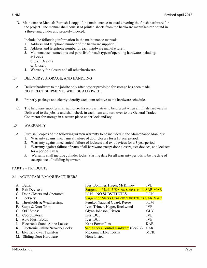
2.1 ACCEPTABLE MANUFACTURERS
A. Butts: Ives, Bommer, Hager, McKinney IVE B. Exit Devices: Sargent or Marks USA-NO SUBSTITUES SAR,MAR C. Door Closers and Operators: LCN – NO SUBSTITUTES LCN D. Locksets: Sargent or Marks USA-NO SUBSTITUES SAR,MAR E. Thresholds & Weatherstrip: Pemko, National Guard, Reese PEM F. Stops & Door Trim: Ives, Trimco, Hager, Rockwood IVE G. O/H Stops: Glynn Johnson, Rixson GLY H. Coordinators: Ives, DCI IVE I. Auto Flush Bolts: Ives, DCI IVE J. Electronic Stand-Alone Locks: Kaba Power Plex KAB K. Electronic Online Network Locks: See Access Control Hardware (Sec2.7) SAR L. Electric Power Transfers: McKinney, Electrolynx MCK M. Sliding Door Hardware None Listed
UNM Revised April 2018
FMLockshop Page
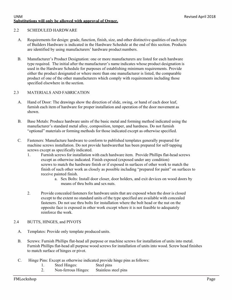
Substitutions will only be allowed with approval of Owner.
2.2 SCHEDULED HARDWARE
A. Requirements for design: grade, function, finish, size, and other distinctive qualities of each type of Builders Hardware is indicated in the Hardware Schedule at the end of this section. Products are identified by using manufacturers’ hardware product numbers.
B. Manufacturer’s Product Designation: one or more manufacturers are listed for each hardware
type required. The initial after the manufacturer’s name indicates whose product designation is used in the Hardware Schedule for purposes of establishing minimum requirements. Provide either the product designated or where more than one manufacturer is listed, the comparable product of one of the other manufacturers which comply with requirements including those specified elsewhere in the section.
2.3 MATERIALS AND FABRICATION
A. Hand of Door: The drawings show the direction of slide, swing, or hand of each door leaf,
furnish each item of hardware for proper installation and operation of the door movement as shown.
B. Base Metals: Produce hardware units of the basic metal and forming method indicated using the
manufacturer’s standard metal alloy, composition, temper, and hardness. Do not furnish “optional” materials or forming methods for those indicated except as otherwise specified.
C. Fasteners: Manufacture hardware to conform to published templates generally prepared for
machine screws installation. Do not provide hardware that has been prepared for self-tapping screws except as specifically indicated. 1. Furnish screws for installation with each hardware item. Provide Phillips flat-head screws
except as otherwise indicated. Finish exposed (exposed under any condition) screws to match the hardware finish or if exposed in surfaces of other work to match the finish of such other work as closely as possible including “prepared for paint” on surfaces to receive painted finish.
a. Sex Bolts: Install door closer, door holders, and exit devices on wood doors by means of thru bolts and sex nuts.
2. Provide concealed fasteners for hardware units that are exposed when the door is closed
except to the extent no standard units of the type specified are available with concealed fasteners. Do not use thru bolts for installation where the bolt head or the nut on the opposite face is exposed in other work except where it is not feasible to adequately reinforce the work.
2.4 BUTTS, HINGES, and PIVOTS
A. Templates: Provide only template produced units.
B. Screws: Furnish Phillips flat-head all purpose or machine screws for installation of units into metal.
Furnish Phillips flat-head all purpose wood screws for installation of units into wood. Screw head finishes to match surface of hinges or pivot.
C. Hinge Pins: Except as otherwise indicated provide hinge pins as follows:
1. Steel Hinges: Steel pins 2. Non-ferrous Hinges: Stainless steel pins
UNM Revised April 2018
FMLockshop Page 25
3. Exterior Doors: Non-removable pins (NRP) 4. Out Swinging Doors: Non-removable pins (NRP) 5. Interior doors: Non-rising pins 6. Tips. Flat button and matching plug finished to match leaves
D. Number of hinges: Provide number of hinges indicated but not less than 3 hinges per door leaf For doors 90” or less in height and 1 additional hinge for each 30” of additional height.
E. Size of hinge leave: 4.5” high, except 5” for doors over 3’6” wide.
F. Width of hinges: Shall be sufficient to clear trim projection when door swings 180 degrees.
G. Fire rated doors over 8’0” shall have heavy weight hinges.
H. All hinges SHALL be made of steel and have steel ball bearings where specified.
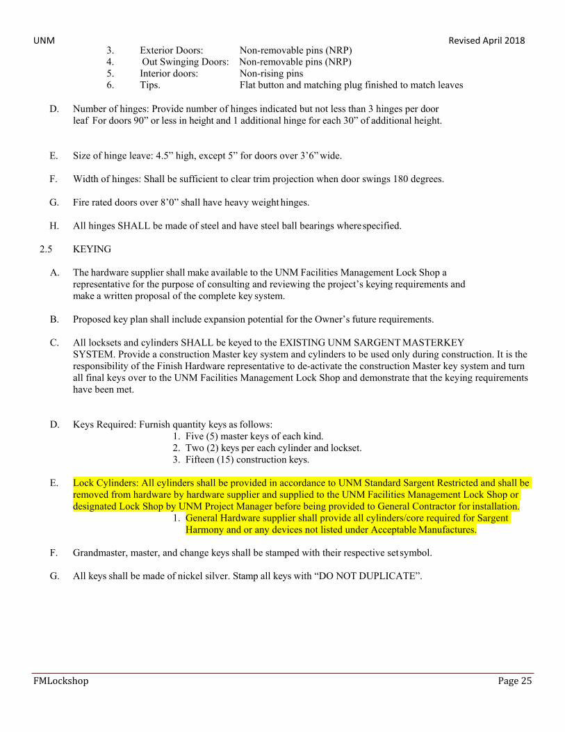
2.5 KEYING
A. The hardware supplier shall make available to the UNM Facilities Management Lock Shop a representative for the purpose of consulting and reviewing the project’s keying requirements and make a written proposal of the complete key system.
B. Proposed key plan shall include expansion potential for the Owner’s future requirements.
C. All locksets and cylinders SHALL be keyed to the EXISTING UNM SARGENT MASTERKEY
SYSTEM. Provide a construction Master key system and cylinders to be used only during construction. It is the responsibility of the Finish Hardware representative to de-activate the construction Master key system and turn all final keys over to the UNM Facilities Management Lock Shop and demonstrate that the keying requirements have been met.
D. Keys Required: Furnish quantity keys as follows: 1. Five (5) master keys of each kind. 2. Two (2) keys per each cylinder and lockset. 3. Fifteen (15) construction keys.
E. Lock Cylinders: All cylinders shall be provided in accordance to UNM Standard Sargent Restricted and shall be removed from hardware by hardware supplier and supplied to the UNM Facilities Management Lock Shop or designated Lock Shop by UNM Project Manager before being provided to General Contractor for installation.
1. General Hardware supplier shall provide all cylinders/core required for Sargent Harmony and or any devices not listed under Acceptable Manufactures.
F. Grandmaster, master, and change keys shall be stamped with their respective set symbol.
G. All keys shall be made of nickel silver. Stamp all keys with “DO NOT DUPLICATE”.
UNM Revised April 2018
FMLockshop Page 26
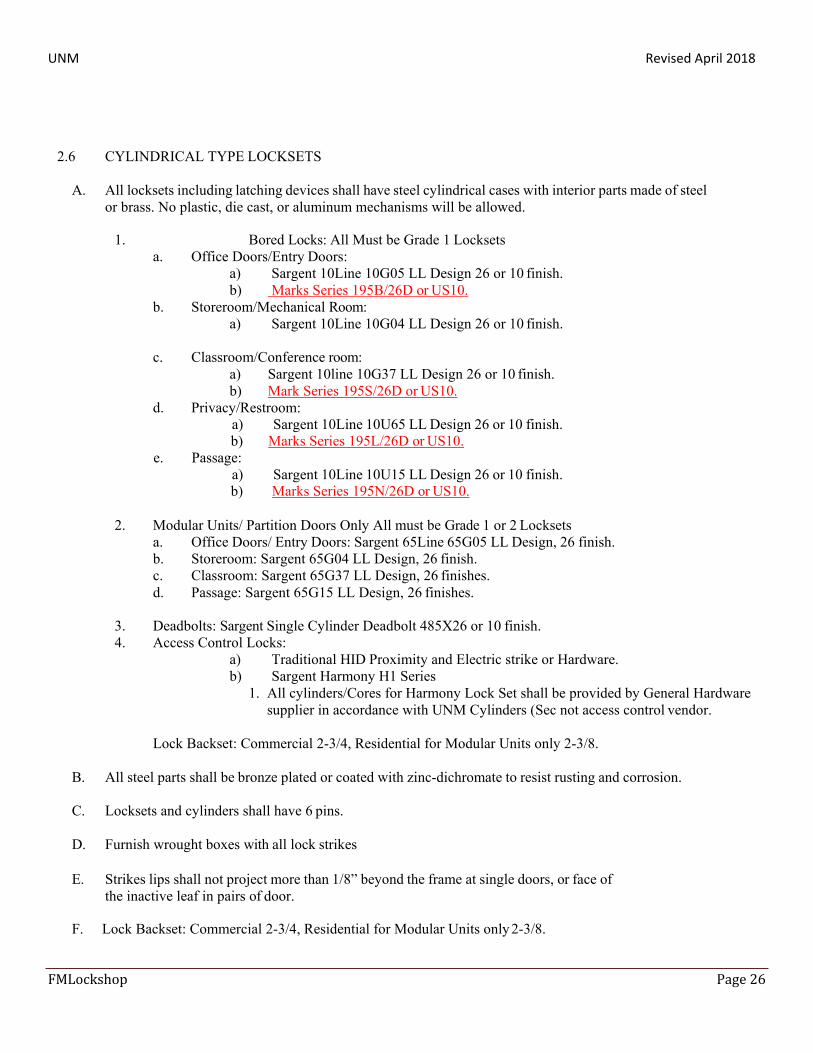
2.6 CYLINDRICAL TYPE LOCKSETS
A. All locksets including latching devices shall have steel cylindrical cases with interior parts made of steel or brass. No plastic, die cast, or aluminum mechanisms will be allowed.
1. Bored Locks: All Must be Grade 1 Locksets
a. Office Doors/Entry Doors: a) Sargent 10Line 10G05 LL Design 26 or 10 finish. b) Marks Series 195B/26D or US10.
b. Storeroom/Mechanical Room: a) Sargent 10Line 10G04 LL Design 26 or 10 finish.
c. Classroom/Conference room:
a) Sargent 10line 10G37 LL Design 26 or 10 finish. b) Mark Series 195S/26D or US10.
d. Privacy/Restroom: a) Sargent 10Line 10U65 LL Design 26 or 10 finish. b) Marks Series 195L/26D or US10.
e. Pass age: a) Sargent 10Line 10U15 LL Design 26 or 10 finish. b) Marks Series 195N/26D or US10.
2. Modular Units/ Partition Doors Only All must be Grade 1 or 2 Locksets
a. Office Doors/ Entry Doors: Sargent 65Line 65G05 LL Design, 26 finish. b. Storeroom: Sargent 65G04 LL Design, 26 finish. c. Classroom: Sargent 65G37 LL Design, 26 finishes. d. Passage: Sargent 65G15 LL Design, 26 finishes.
3. Deadbolts: Sargent Single Cylinder Deadbolt 485X26 or 10 finish. 4. Access Control Locks:
a) Traditional HID Proximity and Electric strike or Hardware. b) Sargent Harmony H1 Series
1. All cylinders/Cores for Harmony Lock Set shall be provided by General Hardware supplier in accordance with UNM Cylinders (Sec not access control vendor.
Lock Backset: Commercial 2-3/4, Residential for Modular Units only 2-3/8.
B. All steel parts shall be bronze plated or coated with zinc-dichromate to resist rusting and corrosion.
C. Locksets and cylinders shall have 6 pins.
D. Furnish wrought boxes with all lock strikes
E. Strikes lips shall not project more than 1/8” beyond the frame at single doors, or face of
the inactive leaf in pairs of door.
F. Lock Backset: Commercial 2-3/4, Residential for Modular Units only 2-3/8.
UNM Revised April 2018
FMLockshop Page 27
2.7 AUXILIARY AND MORTISE DEADLOCKS
A. Bored Auxiliary Locks: a. SARGENT Manufacturing Company; an ASSA ABLOY Group company.
1) Sargent Single cylinder deadbolts Manufacturer # 485 Deadlock in 26 or 10 finish only. 2) DOUBLE CYLINDER DEADBOLTS WILL NOT BE ACCEPTED. 3) Sargent Padlock with a 1”, 2”, 4” shackle heights with a solid brass body with a
boron hardened steel shackle, key with a 10Line cylinder Manufacturer # 858HS. b. Yale Security Inc.; an ASSA ABLOY Group company. c. Master Lock Company
1) Master # 21 rekeyable padlock 1-3/4 wide case 5/16” shackle with at #27 keyway.
B. Mortise Aluminum Store Front Locks: a. Adams Rite Manufacturing Co.; an ASSA ABLOY Group company.
1) Adams Rite 4900 Standard Duty Deadlocking Latch a) Case Size 7/8”x 5 13/16” b) Bolt 5/8”x 1”x 5/8” throw c) Field reversible d) Backset 1-1/8” e) Sargent Mortise 41 six pin cylinder and spacer rings f) Adams Rite 4590 Latch Paddles reversible
2) Adams Rite 1850’s Maximum Security Deadlock
a) Case Size 1”x 6” b) Bolt 5/8” x 1-3/8” throw c) Backset 1-1/8” d) Sargent Mortise 41 six pin cylinder with spacer rings e) Thumb Turn for inside.
b. SARGENT Manufacturing Company; an ASSA ABLOY Group company.
1) Sargent 8400 Mortise exit device narrow style minimum door stile depth required is 1-1/8” + .64”
2) ETL Trim
C. Push-Button Combination Locks:
a. Kaba Ilco Corp.; a Kaba Group company. Simplex Kaba lever must be milled to fit a Sargent IC Core. LL1021-26D-41, LR1021-26D-41
D. Deadlocks shall be mortise type with interior parts made of steel or bronze
E. All steel parts shall be bronze plated or coated with zinc-dichromate to resist rusting and corrosion.
2.8 ELECTRIC STRIKES AND HARDWARE
A. Electric Strikes
Manufacturers: Subject to compliance with requirements, provide products by one of the following available manufacturers offering products that may be incorporated into the Work include, but are not limited to, the following:
a. Adams Rite Manufacturing Co.; an ASSA ABLOY Group company.
UNM Revised April 2018
FMLockshop Page 28
b. Folger Adam Electric Door Controls; an ASSA ABLOY Group company. c. HES, Inc.; an ASSA ABLOY Group company. d. Trine Access Technology. e. Von Duprin; an Ingersoll-Rand company
B. ELECTROMAGNETIC LOCKS
Electromagnetic Locks: BHMA A156.23; electrically powered; with electromagnet attached to frame and armature plate attached to door; full-exterior or full-interior type, as required by application indicated. NOT ACCEPTED.
C. Delayed-Egress Electromagnetic Locks: BHMA A156.24, electrically powered, with electromagnet attached to
frame and armature plate attached to door; depressing push bar for more than 3 seconds initiates irreversible alarm and 15-second delay for egress. When integrated with fire alarm, fire alarm voids 15-second delay.
1. Manufacturers: Subject to compliance with requirements, provide products by one of the following
available manufacturers offering products that may be incorporated into the Work include, but are not limited to, the following:
2. Basis-of-Design Product: Subject to compliance with requirements, provide product indicated on Drawings, schedule or comparable product by one of the following:
E. ELECTROMECHANICAL ONLINE LOCKS: motor or solenoid driven; bored, mortise latch bolt, mortise
deadbolt, mortise deadlocking latch bolt, Cylindrical and Rim Exit device with strike that suits frame.
1. a. SARGENT Manufacturing Company; an ASSA ABLOY Group company
1) Harmony 10L Series Cylindrical locks 2) Harmony 80 Series Exit devices 3) Harmony 82 Series Mortise Locks
b. All devices listed above will be installed with recommended components ( McKinney Hinge’s Electrolynx transfer cables)
F. STAND ALONE ELECTROMECHANICAL OFFLINE LOCKS a. SARGENT Manufacturing Company; an ASSA ABLOY Group company.
1) Profile Series Harmony v.G1.5 b. Alarm Lock Company
1) Trilogy Proxy Lock PDL3000-26D 2) Trilogy Narrow Style Proxy/Pin PDL1300-26D1 3) Trilogy Exit Device Proxy/Pin ETPDLS1ET-R//26D-S88
2.9 Exit Devices and Auxiliary Items:
a. Adams Rite Manufacturing Co.; an ASSA ABLOY Group company. b. SARGENT Manufacturing Company; an ASSA ABLOY Group company.
a) Sargent PP8700 Center & Top Latch Surface Vertical Rods for a pair of doors. b) Sargent SP8700 Center & Top Latch Surface Vertical Rods for a single door. c) Sargent 8700 Surface Vertical rod exit device both bottom and top latching. d) Sargent 8800 series Rim Exit Devices with standard hex or keyed dog down. All entry
doors must have the 04 function unless approved by the University Facilities Management Lock Shop. 8800 series may also be used with electronic access control systems when ordering specify electronic feature.
e) Sargent 8400 Mortise exit device narrow style. Minimum door stile depth required is 1-1/8”+.64”.
UNM Revised April 2018
FMLockshop Page 29
f) All trim for sergeant exit devices should be the ETL design. g) Sargent Lockable Mullion with aluminum prime coat or 10B finish used for exterior
openings. Manufacturer # L980 h) CONCEALED VERTICAL RODS WILL NOT BE ACCEPTED UNLESS
APPROVED BY UNIVERSITY FACILITIES MANAGEMENT LOCK SHOP.
2.10 CLOSER AND DOOR CONTROL DEVICES
A. Surface type door closers shall be fully hydraulic, full rack and pinion action with a one piece forge steel piston 1-1/2” diameter minimum, and have a cast iron case. Hydraulic fluid shall be of a type requiring no seasonal adjustments for temperatures from 120 degrees F. to-30 degrees F.. Pinion shaft shall be minimum of 11/16” diameter. Barrier-free where designated.
B. Separate adjusting valves shall be provided for closing speed, latching speed and backcheck.
C. Adjusting valves shall be made of a metal material, concealed, adjustable only with special wrench
and shall be seated with “O” type rings.
D. All closers shall be supplied with forged steel main arms and outswinging doors to be supplied With HEAVY DUTY forged steel parallel arms.
E. Closers shall NOT be supplied with “Pressure Relief Valves”.
F. LCN Closers; an Ingersoll-Rand company.
1. Standard LCN Door Closer Manufacturer’s # LCN 4000 series handed (4040XP not acceptable) 2. Handicap Door Operators:
a) Z7000 series, 1/10 HP motor with digital closing adjustment, Push and Go, and Touch and Stop features are required with standard wireless battery operated access buttons recommended by vender for current application. Or of Equal quality and performance.
2.11 ELECTRICAL POWER TRANSFERS
A. Electrical Power Transfer (EPT) units shall be fully concealed when the door is closed.
B. EPT shall contain either 2 each 18 gauge stranded or 10 each 24 gauge stranded wires as determined in the hardware sets.
C. EPT shall be UL Fire Listed to be used on Fire Rated Doors.
D. The transfer tube shall be made of stainless steel. “Spring Tubes” are NOT acceptable.
E. “Electric Hinges – McKinney TA2714-26D-QC12 is required for all Sargent Harmony or Electrified hardware.
F. MISCELLANEOUS DOOR TRIM UNITS
A. Material shall be brass, bronze or stainless steel as appropriate for required finish. Brass bronze material to be 0.050” minimum thickness and stainless steel to be 0.050” minimum thickness. Edges of plates to be beveled and polished except lower edge can be square.
B. Width of plates shall be 12” less than door width.
UNM Revised April 2018
FMLockshop Page 30
C. Push Plates: Plate shall be 4” x 16”.
D. Pull Plates: Plate shall be 4” x 16”. Grip shall be extruded or cast bronze or stainless steel located on center of plate.
E. Smoke seal shall be a self-adhesive SILICONE material measuring 3/8” x 1/4”.
2.12 TOOLS FOR MAINTENANCE
A. Furnish a complete set of specialized tools as needed for Owner’s continued adjustment,
maintenance and removal or placement of finish hardware.
2.13 POWER SUPPLIES
A. The power supplies for the electrified locksets and electrified exit devices shall be: 1. UL Listed for Class II applications. 2. 24VDC regulated and filtered. 3. Modular in design. 4. Supplied with battery back-up module and battery pack (10 amp hour capacity.
by the same manufacture as the electrified lockset and electrified exit devices.
B. The power supplies for the Trilogy electrified locksets: 1. 1. By the same manufacture as the Trilogy electrified locksets.
PART 3 – EXECUTION
3.1 INSTALLATION
A. General: All finish hardware shall be installed by General Contractor.
B. Furnish all items of hardware with attachment screws, bolts, nuts, etc., as required to attach
hardware to type of material involved and with finish to match hardware with which they are to be used. Make all attachments to metal by template machine screws.
C. Provide sex nuts and bolts for door closers, forearm shoes of closers, and holding devices.
D. Attached hardware to masonry or concrete with expansion bolts or similar drilled anchors to
Develop full strength of attached device.
E. Run weather-stripping or sound-stripping full height of both jambs and full width of head. Run thresholds full width of opening. Run door bottoms full width of doors. Set expansion anchors in solid masonry, not mortar joints. Set thresholds in caulking by sealant contractor.
3.2 PROTECTION
A. Do not install door silencers, kickplates, pushplates, door bottoms, and wall stops until after
painting is complete. Loosen locksets and panic hardware prior to painting and re-tighten after painting is complete. Mask all hardware or otherwise protect during painting operation.
3.3 ADJUST AND CLEAN
A. Check and adjust each operating item of hardware and each door to ensure proper operation or
UNM Revised April 2018
FMLockshop Page 31
function of every unit. Replace units that cannot be adjusted to operate freely and smoothly as intended for the application made.
B. Final Adjustment: Wherever hardware installation is made more than one month prior to
acceptance or occupancy of a space or area, return to the work during the week prior to acceptance or occupancy and make final check and adjustment of all hardware items in such space or area. Clean operating items as necessary to restore proper function and finish of hardware and doors. Adjust door control devices to compensate for final operation of heating and ventilating’ equipment.
C. Instruct Owner’s personnel in proper adjustment and maintenance of hardware and hardware
finishes during the final adjustment of hardware.
D. Adjust all closers to meet ADA Requirements for sweep time and opening force. Set the closer’s backcheck valve to slow the doors opening from 85 degrees on.
END OF SECTION 08710