Embed Size (px)
Citation preview
SECTION 11.0 – DETENTION TABLE OF CONTENTS
11.1 INTRODUCTION.................................................................................................. 2 11.2 WATER QUALITY ENHANCEMENT................................................................... 2
11.2.1 DRAINAGE MAINTENANCE ....................................................................................2 11.3 STORAGE REQUIREMENTS.............................................................................. 2
11.3.1 AREAS WITHOUT MASTER DRAINAGE PLANS....................................................2 11.3.2 AREAS WITH MASTER DRAINAGE PLANS ...........................................................2 11.3.3 VARIANCES..............................................................................................................3
11.4 DESIGN CRITERIA.............................................................................................. 3 11.4.1 VOLUME AND RELEASE RATE ..............................................................................3 11.4.2 DESIGN FREQUENCY .............................................................................................4 11.4.3 HYDRAULIC DESIGN...............................................................................................4
11.4.3.A WEIR FLOW......................................................................................................5 11.4.3.B ORIFICE FLOW.................................................................................................5
11.5 DESIGN STANDARDS FOR OPEN SPACE DETENTION.................................. 5 11.5.1 STATE ENGINEER'S OFFICE..................................................................................5 11.5.2 GRADING REQUIREMENTS....................................................................................5 11.5.3 FREEBOARD REQUIREMENTS ..............................................................................6 11.5.4 TRICKLE FLOW CHANNELS ...................................................................................6 11.5.5 OUTLET CONFIGURATION .....................................................................................6 11.5.6 EMBANKMENT PROTECTION ................................................................................7 11.5.7 VEGETATION REQUIREMENTS .............................................................................7 11.5.8 MAINTENANCE ACCESS ........................................................................................7
11.6 DESIGN STANDARDS FOR PARKING LOT DETENTION ................................ 7 11.6.1 DEPTH LIMITATION .................................................................................................7 11.6.2 OUTLET CONFIGURATION .....................................................................................7 11.6.3 MAINTENANCE ACCESS ........................................................................................8 11.6.4 FLOOD HAZARD WARNING....................................................................................8
11.7 DESIGN STANDARDS FOR UNDERGROUND DETENTION............................. 8 11.7.1 MATERIALS ..............................................................................................................8 11.7.2 CONFIGURATION ....................................................................................................8 11.7.3 INLET AND OUTLET DESIGN..................................................................................8 11.7.4 MAINTENANCE ACCESS ........................................................................................9
11.8 DESIGN STANDARDS FOR SHEEP DRAW FLOODPLAIN DETENTION......... 9 11.9 DESIGN EXAMPLE - DETENTION VOLUME ................................................... 10 11.10 CHECKLIST ................................................................................................... 13 11.11 CITY ACCEPTANCE OF STORMWATER DETENTION/RETENTION FACILITIES................................................................................................................... 13
Section 11 – Page 1
SECTION 11.0 DETENTION
11.1 INTRODUCTIONThe criteria presented in this section shall be used in the design and evaluation of all detention facilities for the City. The review of all planning submittals (refer to Section 2) shall be based on the criteria presented in this section.
Detention facilities store excess runoff associated with an increase in basin imperviousness and discharge this excess at a rate similar to the rate experienced from the basin without develop-ment. It is intended that the detention facility protect downstream property and improvements, and avoid the overloading of storm drainage facilities located further downstream. If special de-sign conditions exist that cannot be defined by this criteria, the designer shall bring these up with the City during the review process.
The various detention methods are defined on the basis of where the facility is constructed: open space, parking lot, underground. The City permits all methods of detention except for rooftop detention.
Detention facilities shall not be constructed within public right-of-way. The design high water level of detention ponds shall not encroach upon public right-of-way. For additional information see Section 1.2.
11.2 WATER QUALITY ENHANCEMENT Refer to Section 12 – Stormwater Quality Enhancement - for guidelines to incorporate water quality considerations within the design and construction of detention ponds
11.2.1 DRAINAGE MAINTENANCE The property owner shall be responsible for maintenance of all drainage facilities installed pursuant to the development agreement and/or drainage easement agreement. Require-ments include, but are not limited to maintaining the specified storm water detention/retention volumes, maintaining outlet structures, flow restriction devices and facilities needed to con-vey flow to said basin.
Long term operation and maintenance of detention ponds can be found in these Criteria in Section 12 – Stormwater Quality Enhancement.
11.3 STORAGE REQUIREMENTS 11.3.1 AREAS WITHOUT MASTER DRAINAGE PLANS In basins where a master drainage plan has not been approved, the City may require deten-tion storage in accordance with this section to protect irrigation structures or downstream de-velopment. Stormwater runoff shall not be released from developments at a rate greater than the 5-year historical runoff. The amount of runoff detained on-site shall be the differ-ence between the 100-year developed runoff and the 5-year historical runoff. In all cases, detention is required unless proven otherwise.
11.3.2 AREAS WITH MASTER DRAINAGE PLANS Stormwater runoff shall be released from developments in accordance with the master drain-age plan for the area. The release rates may vary from the 5-year historic to the 100-year developed rate. Historic runoff is runoff which occurred under the physiographic conditions prior to any proposed development.
Section 11 – Page 2
In cases where master drainage plans are approved but the improvements have not been constructed (i.e., an adequate outfall to protect downstream property) detention may be re-quired until such time that the outfall is constructed.
11.3.3 VARIANCES For any release rate greater than specified in either Sections 11.3 or 11.4, the Design Engi-neer requesting the variance shall analyze the downstream conditions in detail and show that no adverse effects will occur. This analysis shall include any and all information required by the City. All calculations pertaining to the analysis shall be submitted for review (such as the volume and peak discharge calculations). This analysis shall be submitted to the City in the preliminary and final drainage reports.
Examples of when detention requirements may be varied are: (a) if development occurring on the site decreases the percentage of impervious area already present, (b) if the latter phase of a subdivision is submitted and the previous phases have already met the detention requirements for the entire site, ( c) if a Regional Pond capable of accepting the minimum re-quired detention and water quality capture volume exists, or (d) if development occurring within Redevelopment District and more than 50% of the existing on-site pervious area is be-ing converted to impervious area, then detention is required. Any variances shall be ap-proved by the City and these areas must be thoroughly analyzed to show that no hazards will be created downstream.
Retention ponds are not acceptable unless there is no feasible method for draining the pond by gravity. If a retention pond is found to be the only alternative, the minimum volume of the facility must be adequate to retain the storm runoff from twice the 100-year developed storm event. Percolation/evaporation alone may be an accepted method for draining the pond, but percolation will not be acceptable in situations where an increase in groundwater flow as a result of pond percolation could cause an adverse impact upon structures with basements down gradient of the pond site. For any storm event, if the pond cannot be drained within 3 days permanent pumping facilities shall be required to drain the pond.
11.4 DESIGN CRITERIA 11.4.1 VOLUME AND RELEASE RATE The minimum required volume shall be determined using either: (a) the Rational Formula Method; or (b) the CUHP method as documented in the USDCM Volume 2 "Storage" or the UD SWMM computer program. Utilization of the Rational Formula Method is restricted to basins less than or equal to 5 acres. For basins larger than 5 acres, detention volumes should be determined using the CUHP method or the UD SWMM computer program. Alter-native computer programs for routing flows through detention facilities must be reviewed and approved by the City prior to utilization.
For all detention facilities within the City, the minimum volume of the facility must be ade-quate to detain the storm runoff from the 100-year developed storm event. Off-site flows may pass through the detention facility but not by over-sizing the orifice. Adequate spill-way/outlet capacity shall be provided to safely pass these flows to downstream conveyance elements. Additional information related to minimum storage volumes and maximum release rates from detention ponds can be obtained from the master drainage plans for each major drainage basin.
Procedures for the determination of the required detention volume using the Rational For-mula Method are presented below.
Section 11 – Page 3
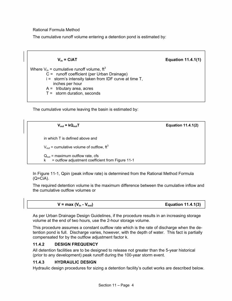
Rational Formula Method
The cumulative runoff volume entering a detention pond is estimated by:
Vin = CiAT Equation 11.4.1(1)
Where Vin = cumulative runoff volume, ft3
C = runoff coefficient (per Urban Drainage) i = storm’s intensity taken from IDF curve at time T, inches per hour A = tributary area, acres T = storm duration, seconds
The cumulative volume leaving the basin is estimated by:
Vout = kQoutT Equation 11.4.1(2) in which T is defined above and
Vout = cumulative volume of outflow, ft3
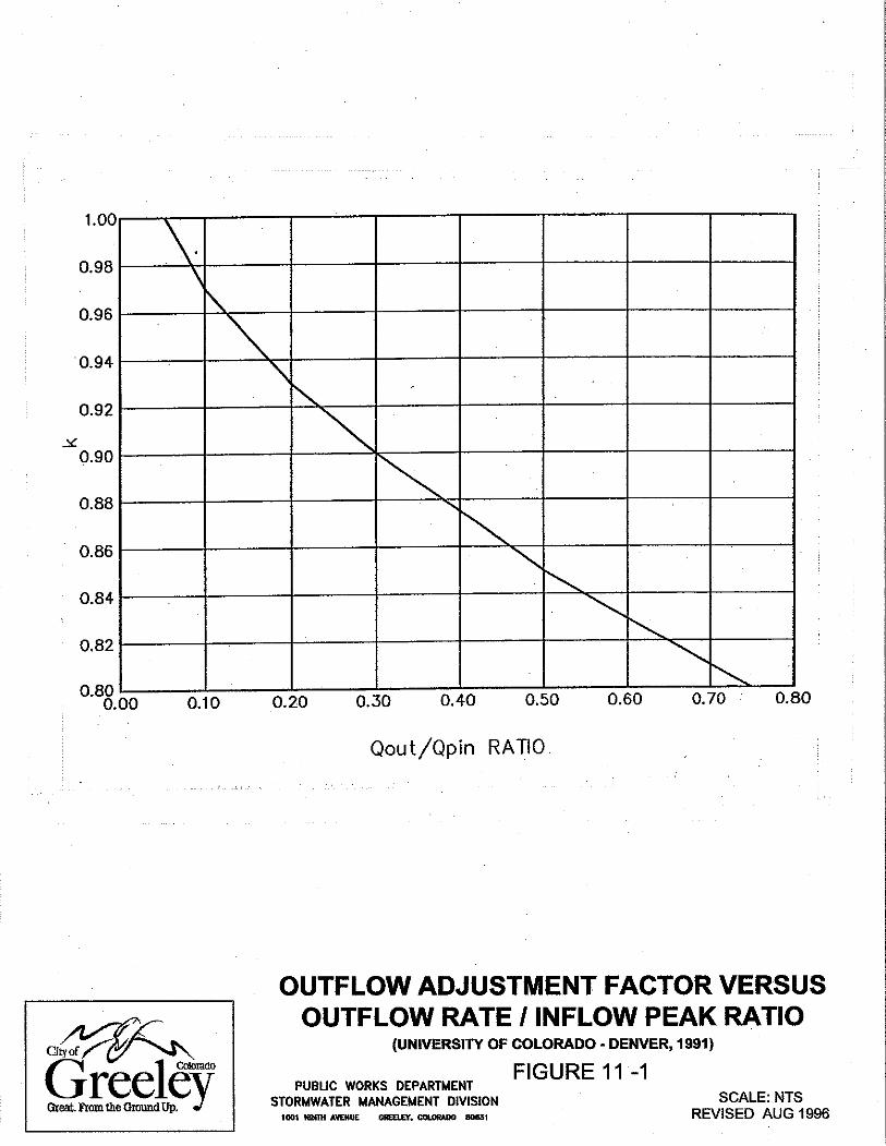
Qout = maximum outflow rate, cfs k = outflow adjustment coefficient from Figure 11-1
In Figure 11-1, Qpin (peak inflow rate) is determined from the Rational Method Formula (Q=CiA).
The required detention volume is the maximum difference between the cumulative inflow and the cumulative outflow volumes or
V = max (Vin - Vout) Equation 11.4.1(3)
As per Urban Drainage Design Guidelines, if the procedure results in an increasing storage volume at the end of two hours, use the 2-hour storage volume.
This procedure assumes a constant outflow rate which is the rate of discharge when the de-tention pond is full. Discharge varies, however, with the depth of water. This fact is partially compensated for by the outflow adjustment factor k.
11.4.2 DESIGN FREQUENCY All detention facilities are to be designed to release not greater than the 5-year historical (prior to any development) peak runoff during the 100-year storm event.
11.4.3 HYDRAULIC DESIGN Hydraulic design procedures for sizing a detention facility’s outlet works are described below.
Section 11 – Page 4
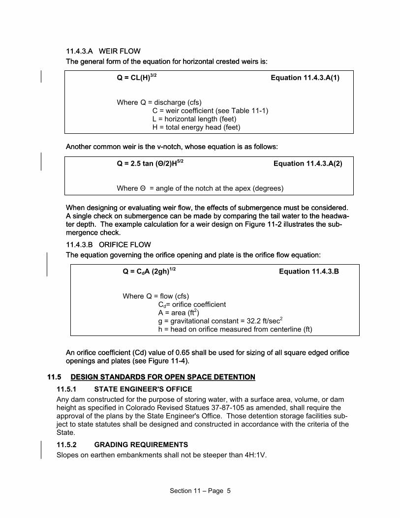
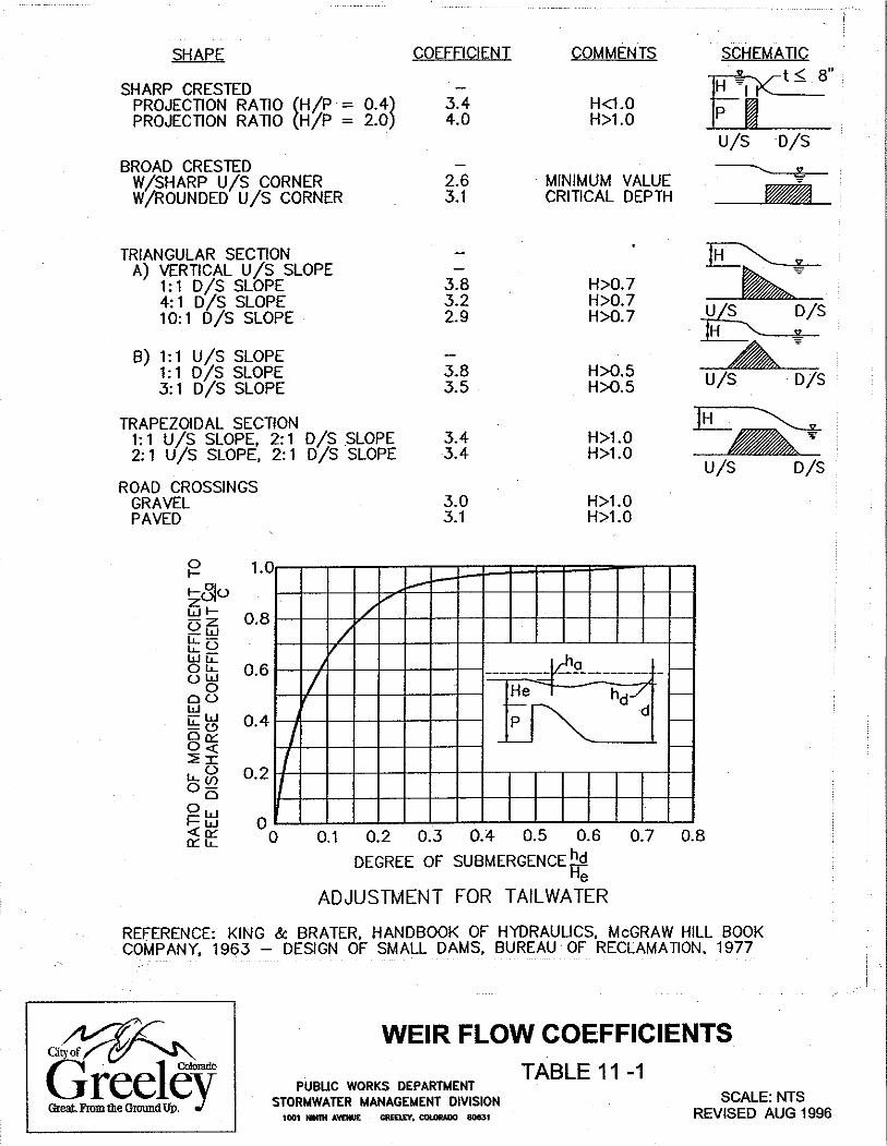
11.4.3.A WEIR FLOW 11.4.3.A WEIR FLOW The general form of the equation for horizontal crested weirs is: The general form of the equation for horizontal crested weirs is:
Q = CL(H)3/2 Equation 11.4.3.A(1)
Where Q = discharge (cfs) C = weir coefficient (see Table 11-1) L = horizontal length (feet) H = total energy head (feet)
Q = 2.5 tan (Θ/2)H5/2 Equation 11.4.3.A(2)
Where Θ = angle of the notch at the apex (degrees)
Q = CdA (2gh)1/2 Equation 11.4.3.B
Where Q = flow (cfs) Cd= orifice coefficient A = area (ft2) g = gravitational constant = 32.2 ft/sec2
h = head on orifice measured from centerline (ft)
Another common weir is the v-notch, whose equation is as follows: Another common weir is the v-notch, whose equation is as follows:
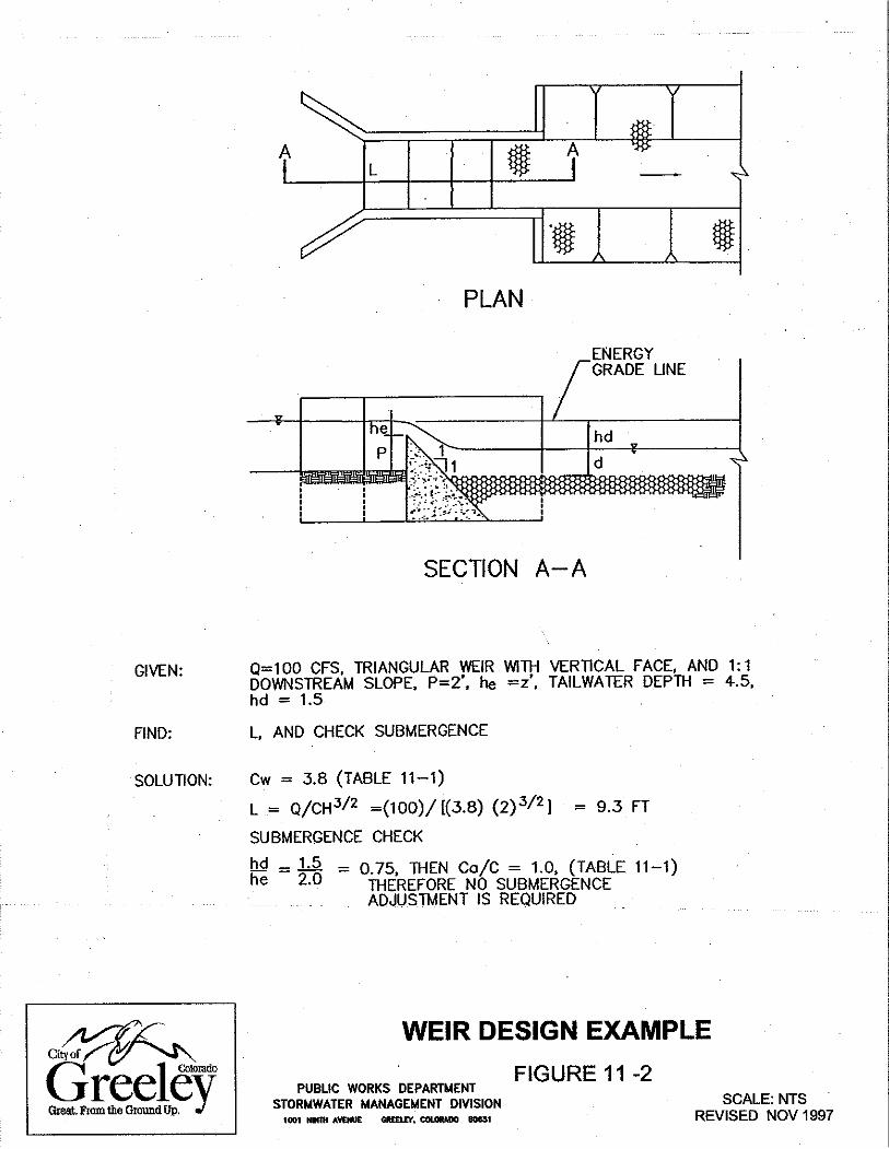
When designing or evaluating weir flow, the effects of submergence must be considered. A single check on submergence can be made by comparing the tail water to the headwa-ter depth. The example calculation for a weir design on Figure 11-2 illustrates the sub-mergence check.
11.4.3.B ORIFICE FLOW 11.4.3.B ORIFICE FLOW The equation governing the orifice opening and plate is the orifice flow equation: The equation governing the orifice opening and plate is the orifice flow equation:
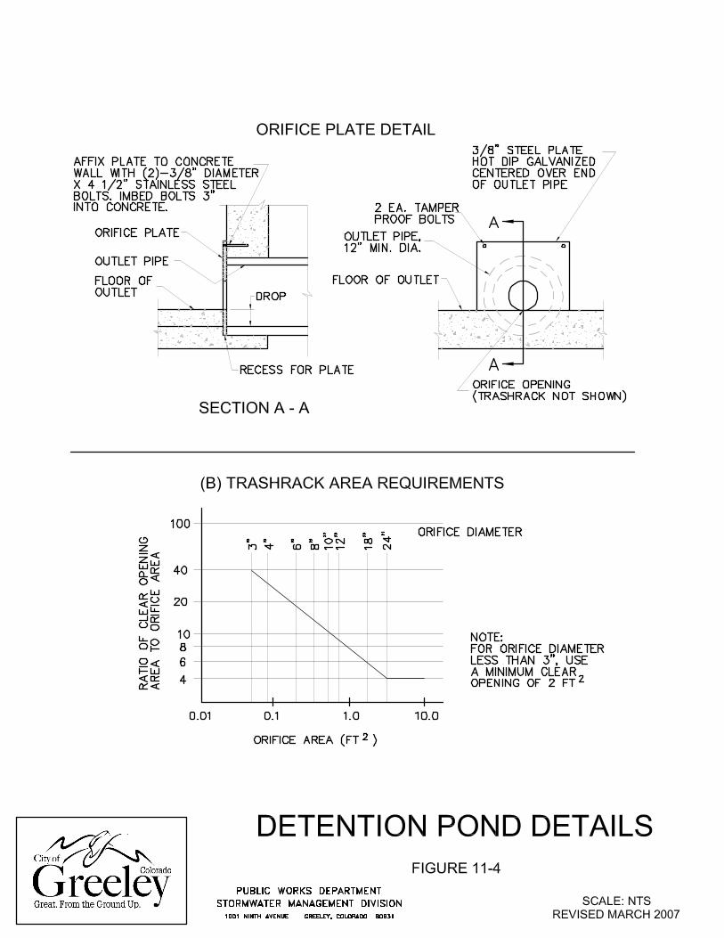
An orifice coefficient (Cd) value of 0.65 shall be used for sizing of all square edged orifice openings and plates (see Figure 11-4). An orifice coefficient (Cd) value of 0.65 shall be used for sizing of all square edged orifice openings and plates (see Figure 11-4).
11.5 DESIGN STANDARDS FOR OPEN SPACE DETENTION11.5
When designing or evaluating weir flow, the effects of submergence must be considered. A single check on submergence can be made by comparing the tail water to the headwa-ter depth. The example calculation for a weir design on Figure 11-2 illustrates the sub-mergence check.
DESIGN STANDARDS FOR OPEN SPACE DETENTION11.5.1 STATE ENGINEER'S OFFICE Any dam constructed for the purpose of storing water, with a surface area, volume, or dam height as specified in Colorado Revised Statues 37-87-105 as amended, shall require the approval of the plans by the State Engineer's Office. Those detention storage facilities sub-ject to state statutes shall be designed and constructed in accordance with the criteria of the State.
11.5.2 GRADING REQUIREMENTS Slopes on earthen embankments shall not be steeper than 4H:1V.
Section 11 – Page 5
For grassed detention facilities, the minimum bottom slope shall be 1.0 percent, measured perpendicular to the trickle channel.
11.5.3 FREEBOARD REQUIREMENTS The minimum required freeboard for detention facilities is one foot above the computed 100-year water surface hydraulic grade line elevation. The invert of the emergency spillway shall be placed at or above the computed on-site 100-year water surface elevation. The com-puted 100-year water surface hydraulic grade line elevation is defined as follows:
A flow situation for which the emergency spillway is passing the 100-year developed on-site flow plus the 100-year off-site flows (if they exist) based on an assumed plugged orifice con-dition.
All state dam safety criteria must be carefully considered when determining the freeboard capacity of ponds which incorporate high embankments or large areas and storage volumes.
11.5.4 TRICKLE FLOW CHANNELS All grassed bottom detention ponds shall include a concrete lined trickle channel. A perfo-rated under drain shall be required if the soils report indicates close proximity to groundwater or groundwater is encountered during construction. Minimum longitudinal slope of trickle channel shall be 0.4%. Trickle flow channel criteria are presented in Section 5.2.2.
11.5.5 OUTLET CONFIGURATION Presented in Figure 11-3 are two examples of a detention pond outlet configuration (see Section 12 for outlet requirements for stormwater quality enhancement). A Type 1 outlet consists of a grated drop inlet, outlet pipe, and an overflow weir in the pond embankment. The outlet will be designed to release the peak discharge associated with the 5-year histori-cal runoff during the 100-year developed runoff. The control for the 100-year peak discharge shall be at the throat of the outlet pipe under the head of water as defined on Figure 11-3. The trash rack must be designed to pass the 5-year historical storm flow with a minimum of 50 percent blockage. Since the minimum size of the outlet pipe is 12 inches, then a control orifice plate at the entrance of the pipe shall be required to control the discharge of the de-sign flow. An example orifice plate is shown in Figure 11-4.
A Type 2 outlet consists of a depressed inlet with an outlet pipe and an overflow weir in the pond embankment. Again, an orifice plate at the entrance shall be required to control the re-lease rate to the 5-year historical peak flow. The control for the 100-year developed condi-tion discharge occurs at the throat of the outlet pipe as shown on Figure 11-3. The outlet pipe must have an adequate slope to ensure throat control in the pipe.
For both outlet types, flows in excess of the developed condition 100-year discharge are re-leased through the overflow weir or spillway. The control orifice plate shall not be oversized to pass release flows from off-site (upstream) detention facilities. The overflow weir or spill-way shall be oversized to pass other off-site flows through the pond. Size the spillway to pass the 100-year developed on-site flow plus the 100-year off-site flows based on an as-sumed plugged orifice condition. The maximum trash rack-opening dimension shall be equal to 6”.
Other outlet configurations will be allowed provided they meet the requirements of the permit-ted release rates at the required volume and include proper provisions for maintenance and reliability. The outlet shall be designed to minimize unauthorized modifications which affect proper function.
Additional storage shall be required to incorporate water quality considerations into the de-sign and construction of a detention pond. Minimum requirements for the implementation
Section 11 – Page 6
and use of detention ponds for stormwater quality control are provided in Section 12.0-Stormwater Quality Enhancement. For information and design guidelines related to the con-struction of detention ponds that promote stormwater quality control, the reader is referred to the Urban Storm Drainage Criteria Manual (USDCM), Volume 3, "Best Management Prac-tices".
11.5.6 EMBANKMENT PROTECTION Whenever a detention pond uses an embankment to contain water, the embankment shall be protected from catastrophic failure due to overtopping. Overtopping can occur when the pond outlets become obstructed or when a larger than 100-year storm occurs.
Failure protection for the embankment may be provided in the form of a 24” deep, Type M, buried riprap layer on the entire downstream face of the embankment or a separate emer-gency spillway having a minimum capacity equal to the 100-year developed storm event for the basin.
Detention facilities in major drainage channels shall have a spillway capacity equal to the 100-year peak discharge associated with fully developed conditions in the basin. Structures shall not be permitted in the path of the emergency spillway or overflow. The invert of the emergency spillway should be set equal to or above the 100-year water surface elevation.
11.5.7 VEGETATION REQUIREMENTS All detention ponds shall be vegetated by either irrigated sod or irrigated native dry land grasses. Refer to Section 14 – Vegetation and Irrigation for these specifications.
No more than one or two deciduous trees, small leaf, maintainable to a single stem, and not inherent to suckering, shall be allowed per 4500 square foot of pond. These trees shall be planted as far away from the outlet structure as possible to prevent plugging the outlet and WCCV holes.
No evergreens shall be allowed in a pond.
11.5.8 MAINTENANCE ACCESS To assure that the detention facility performs as designed, maintenance access shall be pro-vided, and shown on the Final Plat. Regional detention ponds are usually dedicated to the City for operation and maintenance. For privately maintained facilities such as commercial, residential, or industrial sites, an easement shall be granted to the City to allow access and to assure that the facility continues to function as intended. The City has standard easement agreement forms for this purpose.
11.6 DESIGN STANDARDS FOR PARKING LOT DETENTION11.6.1 DEPTH LIMITATION The maximum allowable design depth of ponding is 18 inches for the 100-year flood and 6 inches for the initial storm runoff event. Calculations shall be provided to the City indicating the depth of ponding for the 10-year storm event. Signs shall be posted within parking lots warning users of high water during significant storm events.
11.6.2 OUTLET CONFIGURATION Where a drop inlet is used to discharge to a storm drain or drainage way, the minimum pipe size for the outlet pipe is 12 inches in diameter. Where a weir and a small diameter outlet pipe through a curb are used, the size and shape are dependent on the discharge and stor-age requirements. In this case, a minimum pipe diameter of 4 inches is required.
Section 11 – Page 7
11.6.3 MAINTENANCE ACCESS To assure that the detention facility performs as designed, maintenance access, especially to outlet structures, shall be provided. The outlet shall be designed to minimize unauthorized modifications, which affect function. Any repaving of the parking lot shall be evaluated for impact on volume and release rates and is subject to approval by the City prior to proceeding with the repaving. A sign shall be attached or posted in accordance with Section 11.6.4.
11.6.4 FLOOD HAZARD WARNING All parking lot detention areas shall post a minimum of two signs identifying the detention pond area. The sign shall have a minimum area of 1.5 square feet and contain the following message:
"WARNING"
This area is a detention pond and is subject to periodic flooding depths ranging from a depth of __ (provide the design depth) for the initial storm runoff event to __ (provide the design depth) for the 100-year storm."
Any suitable materials and geometry of the sign are permissible, subject to approval of the City.
11.7 DESIGN STANDARDS FOR UNDERGROUND DETENTION 11.7.1 MATERIALS Underground detention shall be constructed using corrugated aluminum pipe (CAP) or rein-forced concrete pipe (RCP) or other system approved by the City. The pipe thickness, cover, bedding, and backfill shall be designed to withstand HS-20 loading. The minimum diameter of pipe allowed shall be 48”.
A Stormceptor shall be required for the water quality capture volume requirement for all un-derground detention facilities. See Section 6.8.
11.7.2 CONFIGURATION Pipe segments shall be sufficient in number, diameter, and length to provide the required minimum storage volume for the 100-year design. As an option, the initial design storm run-off volume can be stored in the pipe segments and the difference for the 100-year runoff vol-ume stored above the pipe in an open space detention pond, or in parking lot detention.
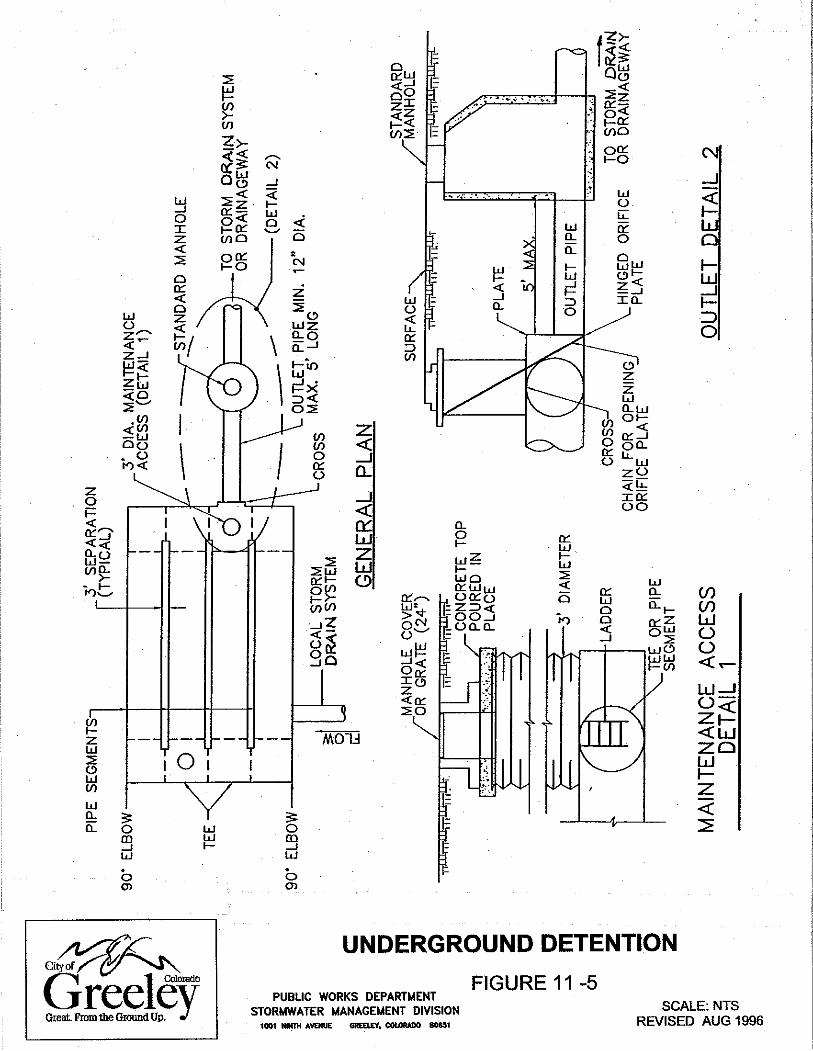
The pipe segments shall be placed side by side and connected at both ends by elbow tee fit-tings and across the fitting at the outlet (see Figure 11-5). The pipe segments shall be con-tinuously sloped at a minimum of 0.4 percent to the outlet. Manholes for maintenance ac-cess (see Section 11.7.4) shall be placed in the tee fittings and in the straight segments of the pipe, when required.
Permanent buildings or structures shall not be placed above the underground detention.
11.7.3 INLET AND OUTLET DESIGN The outlet from the underground detention shall consist of a short (maximum 25 feet) length of CAP or RCP with a 12-inch minimum diameter. The outlet pipe(s) shall discharge into a standard manhole or into a drainage way with erosion protection provided per Sections 9.3.2, 10.2, and 10.3. If an orifice plate is required to control the release rates, the plate shall be hinged to open into the detention pipes to facilitate back flushing of the outlet pipe.
Stormwater access to the detention pipes can be by way of surface inlets and/or by a local private storm drain system. The system shall be designed to accommodate 100 year storm
Section 11 – Page 8
flow rates in order to ensure the 100 year storm will be retained in the underground deten-tion.
Channel rundowns down the slope of detention ponds shall be designed as per Section 5.0, Open Channels, Part 5.5 Channel Rundowns.
11.7.4 MAINTENANCE ACCESS Access easements to the detention site shall be provided. To facilitate cleaning of the pipe segments, 3-foot diameter maintenance access ports shall be placed according to the follow-ing schedule:
MAINTENANCE ACCESS REQUIREMENTS
Detention Pipe Size
Maximum Spacing
Minimum
Frequency
48" to 54"
150'
Every pipe segment
60" to 66"
200'
Every other pipe segment
Greater than 66"
200'
One at each end of the battery of
pipes
Manholes shall be constructed in accordance with Figure 11-5.
11.8 DESIGN STANDARDS FOR SHEEP DRAW FLOODPLAIN DETENTIONThe City of Greeley has, in the past, allowed on-site detention ponds associated with new de-velopment to be constructed within the 100-year floodplain along Sheep Draw. The most recent proposed detention pond in the floodplain is located at Northview Estates just south of C Street – Pond # 1. This issue is discussed in the new updated Comprehensive Drainage Plan (Comp Plan) for Sheep Draw, dated March 8, 2006, section VI. – Miscellaneous Hydrologic and Hy-draulic Issues, Page 6.9, paragraph 6.3 – Construction of On-Site Detention Ponds in the 100-year Sheep Draw Floodplain. The following is the discussion presented in the Comp Plan.
The recent construction of several of these ponds, combined with the anticipation of future pro-posals for more ponds of this nature, prompted an evaluation of this practice. At issue are both the effectiveness and the potential adverse impacts associated with on-site detention ponds lo-cated where Sheep Draw flows would inundate the ponds during flood events. The effective-ness of the ponds to provide the required attenuation of the peak runoff in this situation, as well as potential stability issues with respect to detention pond embankments exposed to Sheep Draw flood flows are both of specific concern. Additional concerns relate to potential impacts to flood levels along Sheep Draw and the stability of the Sheep Draw channel itself.
Based on consideration of hydraulic conditions associated with 100-year flows along Sheep Draw, local versus regional hydrologic response within the basin, and potential erosion issues within the Sheep Draw channel and floodplain, on-site detention ponds may be constructed in the 100-year floodplain along Sheep Draw provided the following six conditions can be satisfied.
1. Considering no impacts from inundation of Sheep Draw flows, the proposed detention pond must reduce the 10-year developed condition peak runoff from the site to no more
Section 11 – Page 9
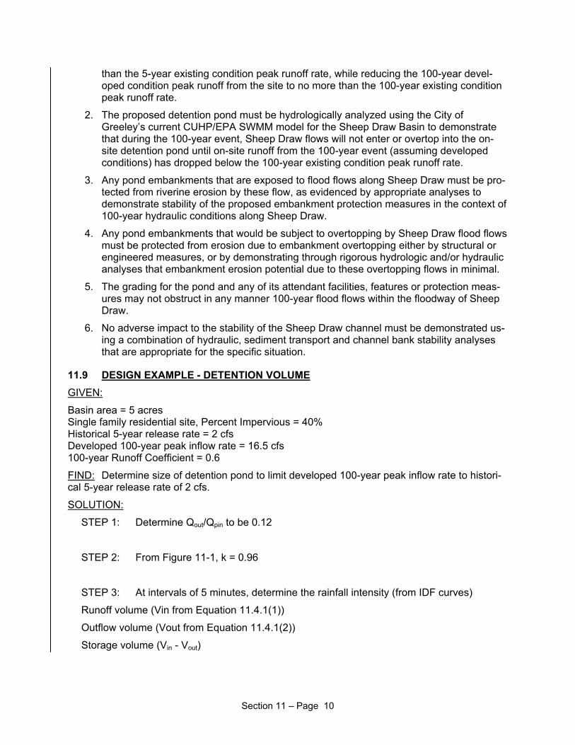
than the 5-year existing condition peak runoff rate, while reducing the 100-year devel-oped condition peak runoff from the site to no more than the 100-year existing condition peak runoff rate.
2. The proposed detention pond must be hydrologically analyzed using the City of Greeley’s current CUHP/EPA SWMM model for the Sheep Draw Basin to demonstrate that during the 100-year event, Sheep Draw flows will not enter or overtop into the on-site detention pond until on-site runoff from the 100-year event (assuming developed conditions) has dropped below the 100-year existing condition peak runoff rate.
3. Any pond embankments that are exposed to flood flows along Sheep Draw must be pro-tected from riverine erosion by these flow, as evidenced by appropriate analyses to demonstrate stability of the proposed embankment protection measures in the context of 100-year hydraulic conditions along Sheep Draw.
4. Any pond embankments that would be subject to overtopping by Sheep Draw flood flows must be protected from erosion due to embankment overtopping either by structural or engineered measures, or by demonstrating through rigorous hydrologic and/or hydraulic analyses that embankment erosion potential due to these overtopping flows in minimal.
5. The grading for the pond and any of its attendant facilities, features or protection meas-ures may not obstruct in any manner 100-year flood flows within the floodway of Sheep Draw.
6. No adverse impact to the stability of the Sheep Draw channel must be demonstrated us-ing a combination of hydraulic, sediment transport and channel bank stability analyses that are appropriate for the specific situation.
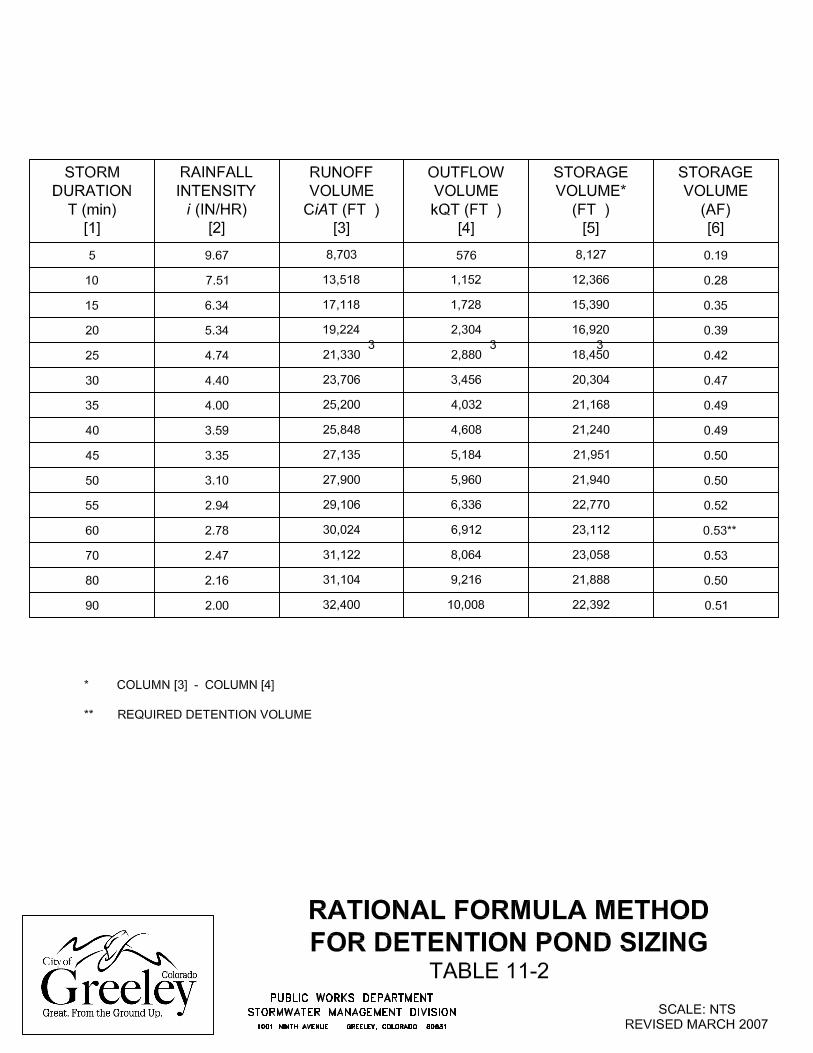
11.9 DESIGN EXAMPLE - DETENTION VOLUME GIVEN:
Basin area = 5 acres Single family residential site, Percent Impervious = 40% Historical 5-year release rate = 2 cfs Developed 100-year peak inflow rate = 16.5 cfs 100-year Runoff Coefficient = 0.6
FIND: Determine size of detention pond to limit developed 100-year peak inflow rate to histori-cal 5-year release rate of 2 cfs.
SOLUTION:
STEP 1: Determine Qout/Qpin to be 0.12
STEP 2: From Figure 11-1, k = 0.96
STEP 3: At intervals of 5 minutes, determine the rainfall intensity (from IDF curves)
Runoff volume (Vin from Equation 11.4.1(1))
Outflow volume (Vout from Equation 11.4.1(2))
Storage volume (Vin - Vout)
Section 11 – Page 10
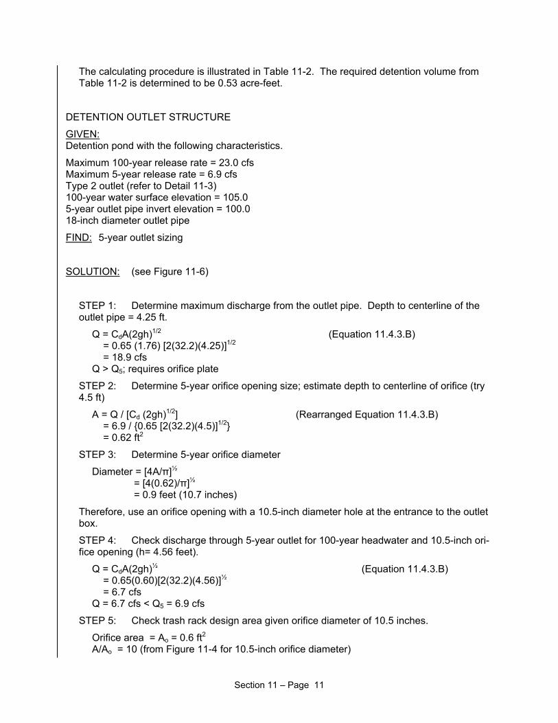
The calculating procedure is illustrated in Table 11-2. The required detention volume from Table 11-2 is determined to be 0.53 acre-feet.
DETENTION OUTLET STRUCTURE
GIVEN: Detention pond with the following characteristics.
Maximum 100-year release rate = 23.0 cfs Maximum 5-year release rate = 6.9 cfs Type 2 outlet (refer to Detail 11-3) 100-year water surface elevation = 105.0 5-year outlet pipe invert elevation = 100.0 18-inch diameter outlet pipe
FIND: 5-year outlet sizing
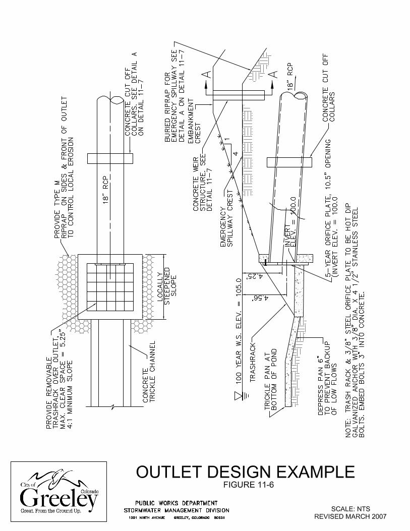
SOLUTION: (see Figure 11-6)
STEP 1: Determine maximum discharge from the outlet pipe. Depth to centerline of the outlet pipe = 4.25 ft.
Q = CdA(2gh)1/2 (Equation 11.4.3.B) = 0.65 (1.76) [2(32.2)(4.25)]1/2 = 18.9 cfs Q > Q5; requires orifice plate
STEP 2: Determine 5-year orifice opening size; estimate depth to centerline of orifice (try 4.5 ft)
A = Q / [Cd (2gh)1/2] (Rearranged Equation 11.4.3.B) = 6.9 / {0.65 [2(32.2)(4.5)]1/2} = 0.62 ft2
STEP 3: Determine 5-year orifice diameter
Diameter = [4A/π]½ = [4(0.62)/π]½ = 0.9 feet (10.7 inches)
Therefore, use an orifice opening with a 10.5-inch diameter hole at the entrance to the outlet box.
STEP 4: Check discharge through 5-year outlet for 100-year headwater and 10.5-inch ori-fice opening (h= 4.56 feet).
Q = CdA(2gh)½ (Equation 11.4.3.B) = 0.65(0.60)[2(32.2)(4.56)]½ = 6.7 cfs Q = 6.7 cfs < Q5 = 6.9 cfs
STEP 5: Check trash rack design area given orifice diameter of 10.5 inches.
Orifice area = Ao = 0.6 ft2 A/Ao = 10 (from Figure 11-4 for 10.5-inch orifice diameter)
Section 11 – Page 11

A = 10(Ao) = 10(0.6) = 6 ft2 Maximum opening = 0.5(10.5) = 5.25 inches
Note: If maximum opening for trash rack is greater than 6” per this equation, use Maximum opening = 6”.
Section 11 – Page 12
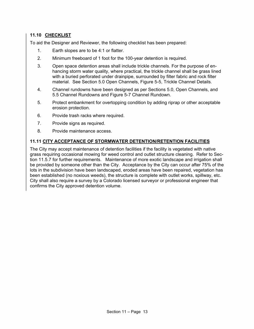
11.10 CHECKLIST To aid the Designer and Reviewer, the following checklist has been prepared:
1. Earth slopes are to be 4:1 or flatter.
2. Minimum freeboard of 1 foot for the 100-year detention is required.
3. Open space detention areas shall include trickle channels. For the purpose of en-hancing storm water quality, where practical, the trickle channel shall be grass lined with a buried perforated under drainpipe, surrounded by filter fabric and rock filter material. See Section 5.0 Open Channels, Figure 5-5, Trickle Channel Details.
4. Channel rundowns have been designed as per Sections 5.0, Open Channels, and 5.5 Channel Rundowns and Figure 5-7 Channel Rundown.
5. Protect embankment for overtopping condition by adding riprap or other acceptable erosion protection.
6. Provide trash racks where required.
7. Provide signs as required.
8. Provide maintenance access.
11.11 CITY ACCEPTANCE OF STORMWATER DETENTION/RETENTION FACILITIES The City may accept maintenance of detention facilities if the facility is vegetated with native grass requiring occasional mowing for weed control and outlet structure cleaning. Refer to Sec-tion 11.5.7 for further requirements. Maintenance of more exotic landscape and irrigation shall be provided by someone other than the City. Acceptance by the City can occur after 75% of the lots in the subdivision have been landscaped, eroded areas have been repaired, vegetation has been established (no noxious weeds), the structure is complete with outlet works, spillway, etc. City shall also require a survey by a Colorado licensed surveyor or professional engineer that confirms the City approved detention volume.
Section 11 – Page 13