Embed Size (px)
Citation preview

Property Services Design Standards and Guidelines
Section 14
Information Systems
Version 1.0

Property Services Design Standards and Guidelines
14 Information Systems
Design Standards and Guidelines © The University of Auckland 14 Information Systems
Version 1.0 Page 2 of 77
Document Control Information
Team Name: Design Standards Steering Group
Published date:
5 September 2019
Document version:
Version 1.0 Revision date: Annually
Document Control
Version Review Date Authorised by Description
1.0 5 September 2019 Design Standards Steering Group
Initial version of manual.
February 2020 (Either note which sections have changed
or ‘annual review – no changes’)
Feedback
If you spot an error in this document, or you have a suggestion on how we can
improve the document, please tell us about it by printing, completing and emailing
the form in Appendix K to us at [email protected].

Property Services Design Standards and Guidelines
14 Information Systems
Design Standards and Guidelines © The University of Auckland 14 Information Systems
Version 1.0 Page 3 of 77
14 Information Systems
Table of Contents
Introduction .................................................................................................. 6
14.1.1 Purpose ....................................................................................................... 6 14.1.2 Applicable standards ..................................................................................... 6 14.1.3 Application ................................................................................................... 6
Design and Approval Process ........................................................................ 7
Abbreviations ................................................................................................ 8
System Information ...................................................................................... 9
14.4.1 General Structure ......................................................................................... 9
Identification and Labelling ........................................................................ 10
General Technical Requirements ................................................................. 11
14.6.1 Specifications for Cabling Contractors ............................................................ 11 14.6.2 Equipment Room (ER) ................................................................................. 11 14.6.3 Telecommunications Room (TR).................................................................... 12 14.6.4 Entrance Room ........................................................................................... 13 14.6.5 Distributor Backing Board ............................................................................ 13 14.6.6 Cabinet or Rack .......................................................................................... 14 14.6.7 Equipment Cords ........................................................................................ 14 14.6.8 Telecommunications Outlets (TO) ................................................................. 14 14.6.9 Electrical outlets ......................................................................................... 17 14.6.10 Underground Ducts ........................................................................... 17 14.6.11 Tunnels ........................................................................................... 17 14.6.12 Pull Boxes ........................................................................................ 17 14.6.13 Cable Trays ...................................................................................... 17 14.6.14 Catenaries ....................................................................................... 18 14.6.15 Building Backbone Cables .................................................................. 18 14.6.16 Horizontal Cables .............................................................................. 18 14.6.17 Existing Cables ................................................................................. 18 14.6.18 Separation and Segregation from Power .............................................. 19 14.6.19 Earthing .......................................................................................... 19
Appendix A Specification for Audio-Visual Cabling ........................................... 20
A.1 General ......................................................................................................... 20 A.2 Description of Works ...................................................................................... 20 A.3 Materials Supply ............................................................................................ 20 A.4 Standards ..................................................................................................... 21 A.5 Catenary Installation ...................................................................................... 22 A.6 Conduit Installation ........................................................................................ 22 A.7 Cable Tray, Troughing or Raceway Installation ................................................... 22 A.8 Earthing ........................................................................................................ 22 A.9 Cable Installation ........................................................................................... 23 A.10 As-Built Documentation .................................................................................. 24 A.11 Testing, Certification and Documentation of Test Results ..................................... 24
Appendix B Specification for Backbone Cabling ................................................ 25
B.1 General ......................................................................................................... 25 B.2 Description of Works ...................................................................................... 25 B.3 Materials Supply ............................................................................................ 25 B.4 Standards ..................................................................................................... 26 B.5 Cables .......................................................................................................... 26

Property Services Design Standards and Guidelines
14 Information Systems
Design Standards and Guidelines © The University of Auckland 14 Information Systems
Version 1.0 Page 4 of 77
B.6 Cable Distributors .......................................................................................... 27 B.7 Equipment Cords ............................................................................................ 28 B.8 Cable Terminations......................................................................................... 28 B.9 Double-ended Patch Cables ............................................................................. 29 B.10 Catenary Installation ...................................................................................... 29 B.11 Cable Tray Installation .................................................................................... 29 B.12 Earthing ........................................................................................................ 29 B.13 Cable Installation ........................................................................................... 30 B.14 As-Built Documentation and Testing ................................................................. 31 B.15 Labelling ....................................................................................................... 31
Appendix C Specification for Cable Trays and Troughing .................................. 32
C.1 Description of Works ...................................................................................... 32 C.2 Materials Supply ............................................................................................ 32 C.3 Standards ..................................................................................................... 32 C.4 Cable Tray Application .................................................................................... 32 C.5 Cable Tray Design .......................................................................................... 33 C.6 Cable Tray Installation .................................................................................... 33 C.7 Earthing ........................................................................................................ 34
Appendix D Specification for Documentation and Testing ................................. 35
D.1 General ......................................................................................................... 35 D.2 As-Built Documentation .................................................................................. 35 D.3 Testing, Certification and Documentation of Test Results ..................................... 36
Appendix E Specification for Horizontal Cabling ............................................... 38
E.1 General ......................................................................................................... 38 E.2 Description of Works ...................................................................................... 38 E.3 Materials Supply ............................................................................................ 38 E.4 Standards ..................................................................................................... 39 E.5 Cables .......................................................................................................... 39 E.6 Cable Terminations......................................................................................... 39 E.7 Double-ended Patch Cables ............................................................................. 40 E.8 Catenary Installation ...................................................................................... 40 E.9 Cable Tray Installation .................................................................................... 40 E.10 Earthing ........................................................................................................ 40 E.11 Cable Installation ........................................................................................... 41 E.12 Telecommunications Outlet Installation ............................................................. 42 E.13 As-Built Documentation and Testing ................................................................. 42 E.14 Labelling ....................................................................................................... 43
Appendix F Specification for Labelling.............................................................. 44
F.1 General ......................................................................................................... 44 F.2 Requirements for Labels.................................................................................. 44 F.3 Labelling Rules ............................................................................................... 45
Appendix G Specification for Pathways in Furniture ......................................... 50
G.1 Design .......................................................................................................... 50 G.2 Fixed Cabling ................................................................................................. 53 G.3 Flexible Work Area Cords ................................................................................ 58
Appendix H Specification for Underground Ducts ............................................. 59
H.1 General ......................................................................................................... 59 H.2 Description of Works ...................................................................................... 59 H.3 Materials Supply ............................................................................................ 59 H.4 As-Built Documentation .................................................................................. 59 H.5 Duct Materials ............................................................................................... 59

Property Services Design Standards and Guidelines
14 Information Systems
Design Standards and Guidelines © The University of Auckland 14 Information Systems
Version 1.0 Page 5 of 77
H.6 Quantities ..................................................................................................... 60 H.7 Depth ........................................................................................................... 60 H.8 Protection and Warning Strip ........................................................................... 60 H.9 Backfilling ..................................................................................................... 60 H.10 Duct Bends .................................................................................................... 60 H.11 Cable Pits ...................................................................................................... 60 H.12 Joints ........................................................................................................... 60 H.13 Building entries .............................................................................................. 61 H.14 Cleaning and Draw Wires ................................................................................ 61 H.15 Disturbance and reinstatement ........................................................................ 61 H.16 Maintenance .................................................................................................. 61
Appendix I Typical Backing Board Layouts ...................................................... 62
I.1 ADC Krone Highband 25 Backmounts ............................................................... 62 I.2 ADC Krone Profil Backmounts .......................................................................... 63
Appendix J Telecommunications Administration Identifiers ............................ 64
J.1 Overview ...................................................................................................... 64 J.2 Scope ........................................................................................................... 64 J.3 Telecommunications Administration Identifiers................................................... 67 J.4 Cabling Identifiers .......................................................................................... 68 J.5 Pathway Identifiers ........................................................................................ 70
Appendix K Feedback Form .............................................................................. 72
Appendix L Index ............................................................................................. 73
List of Tables
Table 1: Information Systems standards ................................................................................................. 6
Table 2: Information Systems abbreviations ........................................................................................... 8
Table 3: Specifications for Cabling Contractors .................................................................................... 11
Table 4: Minimum outlet plate configurations by room area ............................................................. 15
Table 5: Copper Cable Testing Settings .................................................................................................. 37
Table 6: Distributor fields colour coding ................................................................................................. 44
Table 7: Duct colours for hazardous services ........................................................................................ 59
List of Figures
Figure 1: Integrated telecommunications cabling system .................................................................... 9
Figure 2: Access to the telecommunications and electrical compartments .................................... 51
Figure 3: Trunking in the furniture .......................................................................................................... 51
Figure 4: ADC Krone Highband 25 Backmount ..................................................................................... 62
Figure 5: ADC Krone Profil Backmount ................................................................................................... 63
Property Services Design Standards and Guidelines
14 Information Systems
Design Standards and Guidelines © The University of Auckland 14 Information Systems
Version 1.0 Page 6 of 77
Introduction
Introduction
This section shall be specifically read in conjunction with Section 1 About Property
Services Design Standards and Guidelines and Section 2 Project and Building Works
Requirements of the University of Auckland’s Property Services Design Standards and
Guidelines.
14.1.1 Purpose
The purpose of this section is to provide consultants, architects, designers, and
engineers with design guidelines for the planning of spaces and pathways in buildings
for telecommunications equipment and cable network infrastructure.
14.1.2 Applicable standards
This table lists the standards that are applicable to information systems.
These standards shall be referenced in any contract documents that are issued to
telecommunications cabling or related work within University buildings.
Note: The latest version of each applies.
Table 1: Information Systems standards
Standard No Title
AS/NZS 3080:2003 Information technology - Generic cabling for customer premises
AS/NZS 3000:2007 Electrical Installations – Australia/New Zealand Wiring Rules
AS/NZS 3084:2003 Telecommunications Installations – Telecommunications Pathways and Spaces for Commercial Premises
AS/NZS 3085.1:2004 AS/NZS 3080:2003 Telecommunications Installations –
Generic Cabling for Commercial Premises
AS/ACIF S009:2006 Installation Requirements for Customer Cabling
14.1.3 Application
The University of Auckland uses the Standard AS/NZS 3080: 2003 as the primary
reference for the planning and design of the layout of its telecommunications
infrastructure. In order to avoid confusion and misunderstanding the Definitions in
Section 3.1 of that Standard are used in this document and all documentation relating
to telecommunications services. In particular the following definition should be noted:
“3.1.58. Telecommunications
A branch of technology concerned with the transmission, emission and reception of
signs, signals, writing, images and sounds, that is, information of any nature by cable,
radio, optical or other electromagnetic systems. “
Therefore, by definition, the term “telecommunications” includes all telephone, data,
facsimile, modem, video, radio, TV, MATV, control, telemetry, public address, paging,
messaging and like communications systems.
The University of Auckland network is large and geographically dispersed, so that
instead of a single campus distributor there are four campus distributors each serving
a sector of the Main Campus, and separate campus distributors at the Faculty of
Medical and Health Sciences (FMHS) in Grafton, the Faculty of Education (FOED) in
Epsom, the Marine Laboratory at Leigh and at the Tamaki Campus.

Property Services Design Standards and Guidelines
14 Information Systems
Design Standards and Guidelines © The University of Auckland 14 Information Systems
Version 1.0 Page 7 of 77
Design and Approval Process
The design of exclusive spaces and pathways for telecommunications purposes shall
be in accordance with the guidelines in Standard AS/NZS 3084:2003.
Confirmation of the placement, size, layout and fit-out of ER, TR and LC spaces must
be sought from the Network Engineering Manager, ITS or the designated
telecommunications consultants at an early stage in the space allocation planning
process for any new buildings or refurbishment of existing premises.
Likewise, the cable routes and pathways (cable trays, risers, etc.) between these
facilities must be designed in consultation with the Network Engineering Manager,
ITS or the designated telecommunications consultants and confirmed to be of
appropriate size and within the standard distance limits.
The Network Engineering Manager, ITS or the designated telecommunications
consultants will also provide the detailed design specifications and drawings for the
layout of distributors, backing boards and cabinets. It is noted that penetrations,
cable trays and trunking must be dimensioned so that the cable fill does not exceed
40% at installation.

Property Services Design Standards and Guidelines
14 Information Systems
Design Standards and Guidelines © The University of Auckland 14 Information Systems
Version 1.0 Page 8 of 77
Abbreviations
Information systems abbreviations
Table 2: Information Systems abbreviations
Abbreviation Description
BD Building Distributor
BX Building Switch
CD Campus Distributor
ER Equipment Room
FD Floor Distributor
TO Telecommunications Outlet
TR Telecommunications Room
Property Services Design Standards and Guidelines
14 Information Systems
Design Standards and Guidelines © The University of Auckland 14 Information Systems
Version 1.0 Page 9 of 77
System Information
14.4.1 General Structure
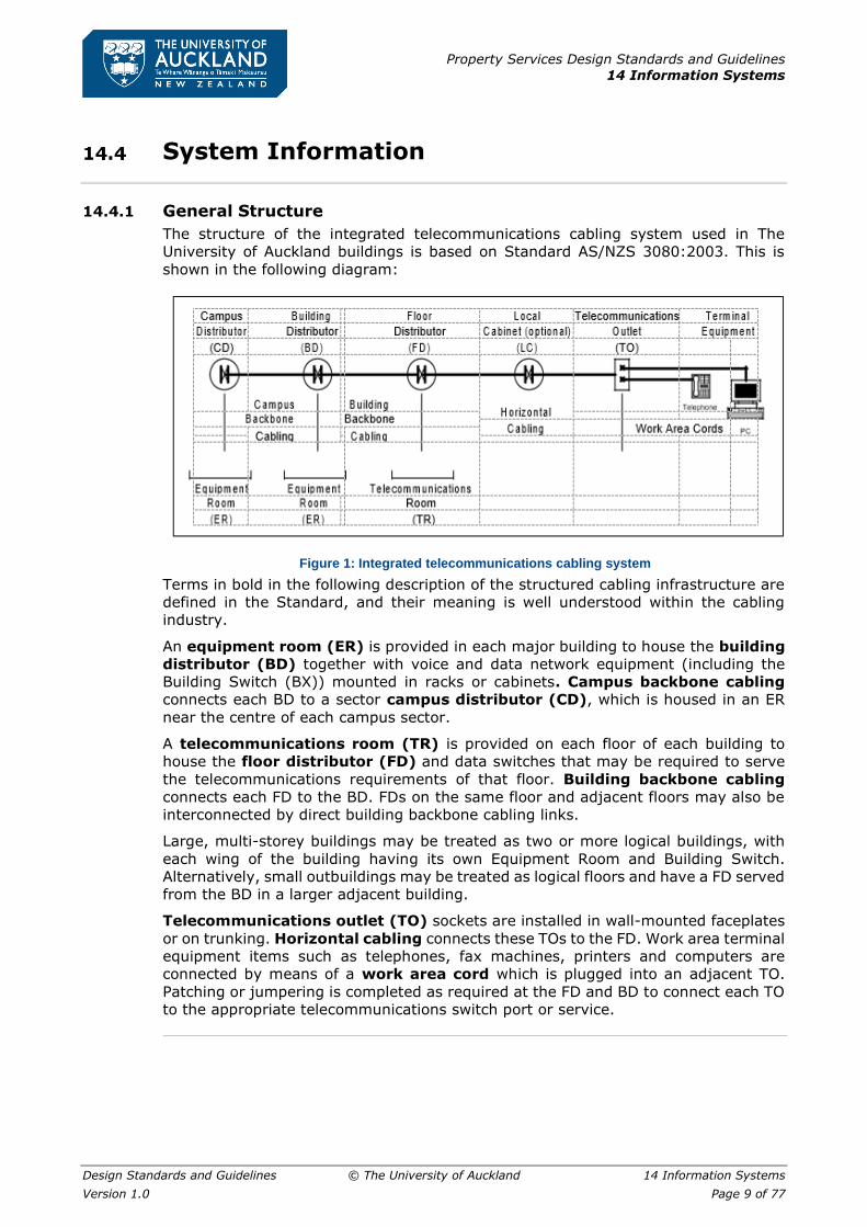
The structure of the integrated telecommunications cabling system used in The
University of Auckland buildings is based on Standard AS/NZS 3080:2003. This is
shown in the following diagram:
Figure 1: Integrated telecommunications cabling system
Terms in bold in the following description of the structured cabling infrastructure are
defined in the Standard, and their meaning is well understood within the cabling
industry.
An equipment room (ER) is provided in each major building to house the building
distributor (BD) together with voice and data network equipment (including the
Building Switch (BX)) mounted in racks or cabinets. Campus backbone cabling
connects each BD to a sector campus distributor (CD), which is housed in an ER
near the centre of each campus sector.
A telecommunications room (TR) is provided on each floor of each building to
house the floor distributor (FD) and data switches that may be required to serve
the telecommunications requirements of that floor. Building backbone cabling
connects each FD to the BD. FDs on the same floor and adjacent floors may also be
interconnected by direct building backbone cabling links.
Large, multi-storey buildings may be treated as two or more logical buildings, with
each wing of the building having its own Equipment Room and Building Switch.
Alternatively, small outbuildings may be treated as logical floors and have a FD served
from the BD in a larger adjacent building.
Telecommunications outlet (TO) sockets are installed in wall-mounted faceplates
or on trunking. Horizontal cabling connects these TOs to the FD. Work area terminal
equipment items such as telephones, fax machines, printers and computers are
connected by means of a work area cord which is plugged into an adjacent TO.
Patching or jumpering is completed as required at the FD and BD to connect each TO
to the appropriate telecommunications switch port or service.

Property Services Design Standards and Guidelines
14 Information Systems
Design Standards and Guidelines © The University of Auckland 14 Information Systems
Version 1.0 Page 10 of 77
Identification and Labelling
The formats of administration identifiers used for record purposes for the cabling
networks of The University of Auckland are detailed in a separate document
“Telecommunications Administration Identifiers” in Appendix C. This document is
based on the principles set out in Standard ANSI/TIA/EIA 606A
All items of telecommunications equipment and hardware require to be labelled. The
information to be shown on the labels is generally either the full administration
identifier or a part of it.
Further details are given in Specification for Labelling on page 44.
Property Services Design Standards and Guidelines
14 Information Systems
Design Standards and Guidelines © The University of Auckland 14 Information Systems
Version 1.0 Page 11 of 77
General Technical Requirements
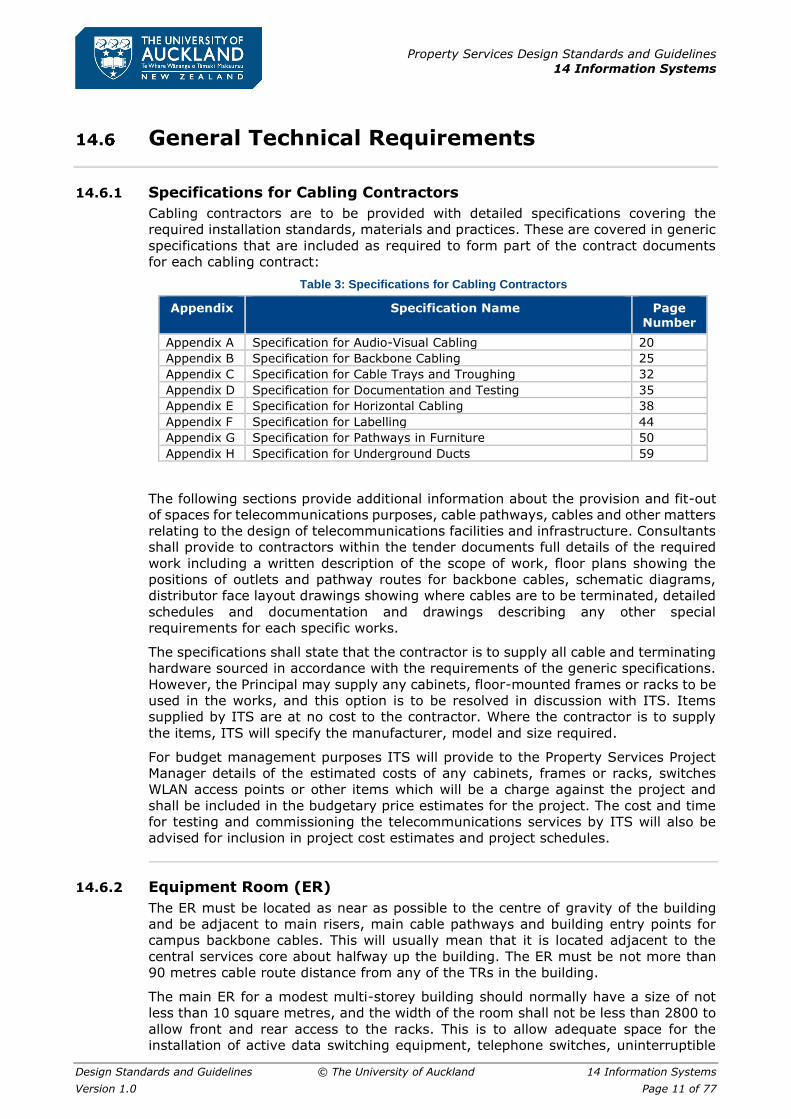
14.6.1 Specifications for Cabling Contractors
Cabling contractors are to be provided with detailed specifications covering the
required installation standards, materials and practices. These are covered in generic
specifications that are included as required to form part of the contract documents
for each cabling contract:
Table 3: Specifications for Cabling Contractors
Appendix Specification Name Page
Number
Appendix A Specification for Audio-Visual Cabling 20
Appendix B Specification for Backbone Cabling 25
Appendix C Specification for Cable Trays and Troughing 32
Appendix D Specification for Documentation and Testing 35
Appendix E Specification for Horizontal Cabling 38
Appendix F Specification for Labelling 44
Appendix G Specification for Pathways in Furniture 50
Appendix H Specification for Underground Ducts 59
The following sections provide additional information about the provision and fit-out
of spaces for telecommunications purposes, cable pathways, cables and other matters
relating to the design of telecommunications facilities and infrastructure. Consultants
shall provide to contractors within the tender documents full details of the required
work including a written description of the scope of work, floor plans showing the
positions of outlets and pathway routes for backbone cables, schematic diagrams,
distributor face layout drawings showing where cables are to be terminated, detailed
schedules and documentation and drawings describing any other special
requirements for each specific works.
The specifications shall state that the contractor is to supply all cable and terminating
hardware sourced in accordance with the requirements of the generic specifications.
However, the Principal may supply any cabinets, floor-mounted frames or racks to be
used in the works, and this option is to be resolved in discussion with ITS. Items
supplied by ITS are at no cost to the contractor. Where the contractor is to supply
the items, ITS will specify the manufacturer, model and size required.
For budget management purposes ITS will provide to the Property Services Project
Manager details of the estimated costs of any cabinets, frames or racks, switches
WLAN access points or other items which will be a charge against the project and
shall be included in the budgetary price estimates for the project. The cost and time
for testing and commissioning the telecommunications services by ITS will also be
advised for inclusion in project cost estimates and project schedules.
14.6.2 Equipment Room (ER)
The ER must be located as near as possible to the centre of gravity of the building
and be adjacent to main risers, main cable pathways and building entry points for
campus backbone cables. This will usually mean that it is located adjacent to the
central services core about halfway up the building. The ER must be not more than
90 metres cable route distance from any of the TRs in the building.
The main ER for a modest multi-storey building should normally have a size of not
less than 10 square metres, and the width of the room shall not be less than 2800 to
allow front and rear access to the racks. This is to allow adequate space for the
installation of active data switching equipment, telephone switches, uninterruptible
Property Services Design Standards and Guidelines
14 Information Systems
Design Standards and Guidelines © The University of Auckland 14 Information Systems
Version 1.0 Page 12 of 77
power supplies, optical fibre transmission equipment and cable termination frames.
Many buildings will require larger equipment rooms, typically of an area equal to 1%
of the total floor area of the building in cases where server equipment is to be
accommodated. Design should allow for the size of the equipment room to be
increased if required later in the life of the building.
Design is based on the considerations in AS/NZS 3084:2003, Section 6.4 and Section
ZB2.3. HVAC requirements are covered in Section ZB2.3.4.6, where the temperature
range is specified as 18 to 24 degrees C, and the Relative Humidity between 30
and55%. As lead-acid recombination type or similar back-up batteries will be included
in UPS equipment housed in the ER then air-conditioning will be required to keep the
temperature at not more than 21oC to preserve the service life of the battery.
The ER should have an outward opening door at least 900 wide giving direct access
from a “public” area such as a corridor. There must be good access from a loading
dock, lift or similar place suitable for equipment delivery. Door locking is to be keyed
to the University PABX Room master key system.
Equipment rooms shall not have water pipes, drainpipes, other piping or ductwork
installed in, over, passing through or entering the room. They must be located at
least two metres away from significant sources of EMF such as power transformers,
large electric motors, generators and main electrical switchgear.
The floor loading capacity must be sufficient to carry both the distributed and
concentrated load of the installed equipment. In general, the distributed load -bearing
capacity shall be greater than 4.8 kPa and the concentrated loading capacity at rack
locations shall be greater than 8.8 kN.
Lighting is required in each room to meet the requirements of Section ZB2.3.4.8. A
level of 500 lux is required at 1m above floor level.
A liberal provision of electrical socket outlets is appropriate. The outlets serving the
equipment racks must be on separate sub-circuits from other outlets and must not
be on a circuit that is protected by an RCD. A 20A PDL 56 Series socket outlet is
required adjacent to the rack for the connection of a UPS.
All wall and floor penetrations for cable pathways are to be fire-stopped. Floor
penetrations in and above equipment rooms are to be bunded to a height of at least
50mm to prevent water running down cable risers and damaging cables and
equipment.
Floor-standing racks and cabinets are to be secured to the floor to prevent toppling.
Top bracing is not required for open-frame cabinets but must be provided for floor
mounted frames. This will usually comprise Unistrut type members in a triangular
arrangement attached to structurally adequate walls. Where multiple racks or
cabinets are installed in a row, adjacent cabinets shall be securely fastened together.
14.6.3 Telecommunications Room (TR)
Each telecommunications room should be located at the centre of the area that it is
to serve, and wherever possible not more than 90 metres cable distance from the ER.
No part of the service area may be more than 90 metres cable distance from the TR.
This usually means that the TR must not be more than about 50 metres in a direct
line from any part of the floor that it serves. If the service area is more than about
100 metres long, then two TRs will generally be required.
Each TR for a typical building floor shall have an area of at least 8 square meters to
allow for the accommodation of all telecommunications equipment and terminations,
and to allow for growth during the life of the building. Generally, expansion of the TR
at a later date will not be a practicable option.

Property Services Design Standards and Guidelines
14 Information Systems
Design Standards and Guidelines © The University of Auckland 14 Information Systems
Version 1.0 Page 13 of 77
The location of the TR should preferably be in or immediately adjacent to a service
core area that is unlikely to be disturbed if the building is renovated or refurbished at
a later date. Telecommunications rooms must be dedicated to telecommunications
functions only and not be shared with electrical installations other than those for
telecommunications purposes, shared with other users, or used as a storeroom.
Design is based on the considerations in AS/NZS 3084:2003, Section 6.3 and Section
ZB2.2. HVAC requirements are covered in Section 6.3 and ZB2.2.7. The heat
generated by active equipment will require positive pressure forced air ventilation
from an adjoining corridor or office space. However, where a lead-acid recombination
type or similar back-up battery is included in any equipment housed in the TR then
air-conditioning will be required to keep the air temperature at not more than 21oC
to preserve the service life of the battery. Planning for the eventual provision of air-
conditioning operating 24 hours per day, 365 days per year, should be included in
the design considerations of any TR in a new or refurbished area.
Lighting is required in each room to meet the requirements of Section ZB2.2.4.1. A
level of 500 lux is required.
A liberal provision of electrical socket outlets is appropriate. The outlets serving the
equipment rack must be on a separate sub-circuit from other outlets and must not
be on a circuit that is protected by an RCD.
The door lock is to be keyed to the University PABX Room master key system.
All wall and floor penetrations for cable pathways are to be fire-stopped. Floor
penetrations in and above telecommunications rooms shall be bunded to a height of
at least 50mm to prevent water from flowing down cable risers.
14.6.4 Entrance Room
An entrance room may be required to accommodate the interface terminations and
equipment between the building infrastructure and campus cabling or the cabling of
other Service Providers. Space may be
required for cable distributors, racks or splice closures to accommodate changes from
outdoor type cables to indoor type cables. A cable handling pit in the footway outside
the building and ducts through the building foundation or wall into the entrance room
may be required for both University network cables and other Service Provider cables.
Entrance Rooms must be located within 5 metres of the point of entry and in an area
that is dry and not subject to flooding. The entrance ducts must be sealed against the
ingress of moisture, gases or rodents.
In major buildings an alternate entrance facility may be provided to give a separate
path to the campus distributor and thus improve network availability.
14.6.5 Distributor Backing Board
A backing board is installed in each ER and TR for the purpose of mounting the
distributor and other equipment. The backing board is a panel of white plastic coated
(or painted) plywood, 19mm thick and mounted on 100mm vertical timber framing
at approximately 600mm centres to provide a space behind the backing board for
concealing cables. The intermediate framing timbers are interrupted to allow cables
to be run horizontally behind the backing board. Typical backing board layouts are
shown in 0. Krone 66-way Profil backmounts or Highband 25-pair backmounts are
installed on the backing board.
The position and size of each backing board is to be confirmed with the Network
Engineering Manager, ITS, or the consultants before installation.

Property Services Design Standards and Guidelines
14 Information Systems
Design Standards and Guidelines © The University of Auckland 14 Information Systems
Version 1.0 Page 14 of 77
A dual switched electrical socket outlet is to be installed on or immediately below each
backing board. All electrical outlets other than those feeding the rack are to be on a
single dedicated sub-circuit
14.6.6 Cabinet or Rack
The University may supply an open sided floor-standing cabinet or rack where
required to accommodate switches and optical fibre cable terminations. The size and
position of the rack or cabinet is to be advised by the Network Engineering Manager,
ITS or the consultant. A typical rack will have an 800 x 800 footprint and requires a
1000 clear workspace in front and 800 behind.
Any equipment or cable terminations must be installed at least 200mm above floor
level.
14.6.7 Equipment Cords
Equipment cords (sometimes referred to as “data fly leads” or “hydras”) are installed
between termination modules on the ADC Krone backmounts and the rack or cabinet.
Quantities and other details are to be confirmed with the Network Engineering
Manager, ITS or the consultants. Normally at least two groups of 26 stranded copper
equipment cords, blue in colour, will be required.
14.6.8 Telecommunications Outlets (TO)
The telecommunications outlets specified by the Standard are 8-position modular
sockets, which are sometimes (incorrectly) referred to as RJ45 sockets. The pin-out
pair assignment used by the University for all new work is T568A.
Only ADC Krone sockets shall be used. Only PDL 500 or 600 series or Worktop style
face plates shall be used. Adaptors are available with label bezels for use in PDL
500/600 series or Worktop style face plates.
A double telecommunications outlet in a flush mounted faceplate is the standard
provision for each workstation or desk position in office and general areas. Faceplates
are usually installed in flush-boxes at 300 to 380mm or at 1200mm above floor level,
but in any case, their positioning must be co-ordinated with electrical socket outlets
(refer to 14.6.9 Electrical outlets on page 17). C-clips shall not be used in place of
flush boxes, but plastic, clip-in boxes may be used where outlets are being retrofitted.
Plates for electrical and telecommunications outlets should be spaced horizontally at
150mm centres on the same level either side of a wall stud, or, if required at different
heights they should be placed centrally one above the other, but the cables should
be routed to opposite sides of a stud as they pass up inside the wall cavity to the
ceiling space.
The density of provision should include service at all potential workstation or desk
positions, allowing for desks to be rearranged to suit the requirements of the
occupants. To achieve this, at least one double outlet plate should be installed for
each 6.5 square metres of usable office space, or part thereof. However, in order to
ensure that all parts of the room are able to be reached by a standard 3 metre work
area cord there should be an outlet plate for each 6 metres, or part thereof, of usable
perimeter wall.
The minimum provision for a work area shall be two outlet plates on opposite walls,
as required by AS/NZS 3084:2003, Clause 6.2.
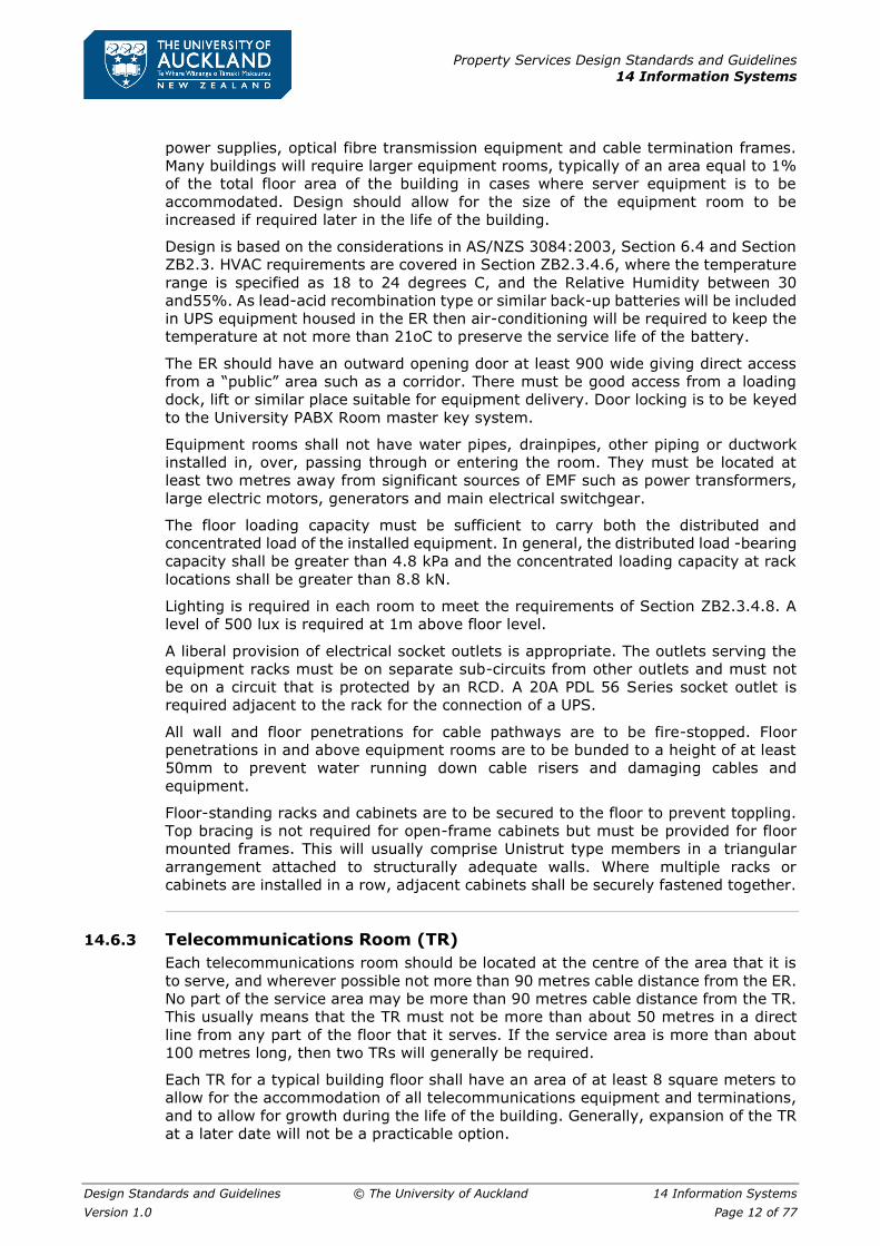
With regularly proportioned rooms these minimum outlet configurations will be
required:
Property Services Design Standards and Guidelines
14 Information Systems
Design Standards and Guidelines © The University of Auckland 14 Information Systems
Version 1.0 Page 15 of 77
Table 4: Minimum outlet plate configurations by room area
Room area (m2) Outlet plate configuration
0.0 – 12.0 2 x double
12.0 to 19.5 3 x double
19.5 to 26.0 4 x double
26.0 to 32.5 5 x double
In order to ensure that access is unlikely to be obstructed by the slab-ends of desks
or other furniture, outlets should be positioned at least 900mm from any internal
corner.
For areas of unusual shape or with obstructions such as protruding columns, different
configurations may be required.
The minimum size of outlet plate to be installed is a double telecommunications
outlet. Single outlet plates are not to be used.
Any requirements for electrical and telecommunications outlets to serve photocopiers,
printers, facsimile machines, vending machines, lift telephones, public telephones,
information kiosks, wireless LAN access points, ceiling mounted projectors, EFTPOS
terminals, IP video cameras, people counters, BMS or lighting controllers and other
purposes should not be overlooked.
For other workspaces a double telecommunications outlet in a flush mounted
faceplate or on trunking is installed at each point where service is likely to be required.
In laboratories and wet areas other arrangements as described below may be
appropriate.
Laboratories and Built-in Benches
Apart from outlets below whiteboards or at desk positions, all outlets in laboratories
should be installed above bench level and co-ordinated with adjacent power outlets.
Where appropriate, shuttered outlets should be used.
Classrooms
Outlets are normally installed on trunking beneath the desktop at the back of the
desks. Desks must be fixed to the floor. Alternatively, desks can be serviced using
“soft wiring” from wall mounted outlets or from floor boxes. For further considerations
relating to cabling within furniture and partitions refer to Appendix G Specification for
Pathways in Furniture on page 50.
Cable Trunking
Where trunking is provided the telecommunications outlets should be installed in the
upper portion of the trunking using worktop or architrave type faceplates. Where the
Contractor is to supply and install trunking this is identified in the Work Schedule.
The approved trunking types are:
▪ Interserv 180/2 and 150/2 Cat6 Trunking
▪ Modempak Cat6 Skirting Trunking (170mm)
▪ Unistrut TD180 and TD155 Cat6 Skirting Duct
The normal requirement is for two compartments meeting segregation requirements,
in colour grey, beige or cream. It is preferred that trunking be installed at a
convenient working height and not at floor level.
The compartment for data cables must be dimensioned so that the initial cable fill
does not exceed 40%. This means, for example, that a 60x60 trunking compartment
can accommodate no more than twenty-eight 7mm diameter cables at installation.

Property Services Design Standards and Guidelines
14 Information Systems
Design Standards and Guidelines © The University of Auckland 14 Information Systems
Version 1.0 Page 16 of 77
For further considerations relating to cabling within furniture and partitions refer to
refer to Appendix G Specification for Pathways in Furniture on page 50.
Wet Laboratories
In wet areas and other designated areas, the wall outlets are to be mounted at a
height of approximately 2400mm above floor level.
Mid-floor Ceiling Droppers
Where mid-floor services are required in laboratories then 4-way or, 6-way outlet box
assemblies with multiple four-pair Cat 6 cables contained within flexible conduit are
to be installed. The assemblies are to be suspended from a secure screw eye by
means of a galvanised steel chain at a height co-ordinated with suspended electrical
outlets. The pre-fabricated boxes or assemblies may be obtained from Willis
Consulting Limited.
Service Poles
In areas with island clusters of furniture or freestanding partitions the outlets may be
cabled via a service pole from the ceiling. The outlets are to be installed on the service
pole or partitions as for wall trunking.
Service poles must be rigidly fixed to the building structure. Care is to be taken to
observe separation, segregation and earthing requirements when both electrical and
telecommunications cables are reticulated in the same service pole.
For further considerations relating to cabling within furniture and partitions refer to
refer to Appendix G Specification for Pathways in Furniture on page 50.
Floor boxes or troughing
In areas with island clusters of furniture or freestanding partitions the outlets may to
be cabled from a floor penetration, floor box or troughing channel. The outlets are to
be installed on the furniture or partitions as for wall trunking or may use “soft wiring”
from the floor box. Furniture fed in this way must be fixed to the floor. Furniture fed
from floor boxes shall be positioned so that cables exiting the floor boxes are not
subject to kicking or damage from shoes, etc.
Refer to AS/NZS 3084:2003, Section 7.10, for further considerations relating to the
design and use of floor troughing.
Furniture Pathways
A coordinated approach must be taken to the design of furniture pathways. In order
to ensure compliance with the electrical safety requirements of the electrical Wiring
Rules (AS/NZS 3000: 2007), and the requirements of AS/NZS 3084:2003, which in
turn requires compliance with AS/ACIF S009:2006, particular attention must be paid
to:
▪ The strategy for connecting building pathways to furniture pathways.
▪ The number, type and location of outlets and outlet plates.
▪ The size and minimum bend radius of each cable type.
▪ Pathway cross sections and cable capacities, angles and transitions.
▪ Separation and segregation from electrical cables.
▪ Separation of electrical and telecommunications compartment cover plates.
▪ Earthing of metalwork.
▪ Fixing of furniture to the floor.
▪ Protection of cables rising up from floor troughs or boxes.
These considerations are covered in more detail in to refer to Appendix G Specification
for Pathways in Furniture on page 50. Recommended design guidelines are included.

Property Services Design Standards and Guidelines
14 Information Systems
Design Standards and Guidelines © The University of Auckland 14 Information Systems
Version 1.0 Page 17 of 77
14.6.9 Electrical outlets
The Standard AS/NZS 3084:2003 recommends in Clause 6.2 that a minimum of one
power outlet should be installed with each telecommunications outlet. This means
that a double electrical outlet should be installed adjacent to each double TO, and two
double electrical outlets or a four-way electrical outlet should be installed adjacent to
each triple or quad TO.
14.6.10 Underground Ducts
Campus backbone cables between buildings will generally be installed in underground
ducts. Lead-ins to building entry points will generally have two 100mm UPVC ducts.
For further details refer to Appendix H Specification for Underground Ducts on page
59.
Underground ducts shall include a drainage facility external to the building entrance
point so that water entering the duct system cannot enter the building. Consideration
should be given to the drainage of all pits on the duct route.
Telecommunications duct systems and pits should never be used as pathways for
electrical cables or other non-telecommunications services.
The lids of maintenance holes and pits shall be designed for full roadway loading if
there is any possibility that a vehicle may pass over them. Lids must be fitted with
locks to prevent unauthorised access. The keying of the locks must differ from those
used by Telecom and other major service providers.
14.6.11 Tunnels
Campus backbone cables between buildings may be installed in utility services
tunnels. Not only must the required separation from electrical cables be observed but
heating effects from hot water and steam pipes must be considered.
14.6.12 Pull Boxes
Readily accessible pull boxes may be required in ducted pathways to facilitate the
installation of draw wires and cables. They are installed in straight sections of the
duct, and not used in lieu of bends.
14.6.13 Cable Trays
Cable trays will be installed for cable support on all backbone cable routes and on
major horizontal cable routes. Generally, cable trays will be required where there are
more than 32 four-pair cables, but multiple catenary wires may be used in these
situations where the installation of trays would be impractical.
Cable trays must have flat bottoms and be at least 100mm deep with no sharp edges.
Cable ladder, ladder tray, mesh tray or tray with a deformed or corrugated bottom
surface is not permitted. Where trays are installed in open ceiling areas, they must
be fitted with lids to provide protection for the cables. All tee-junctions and bends
must have curved sides with a radius of not less than 50mm.
For further details refer to Appendix C Specification for Cable Trays and Troughing on
page 32.

Property Services Design Standards and Guidelines
14 Information Systems
Design Standards and Guidelines © The University of Auckland 14 Information Systems
Version 1.0 Page 18 of 77
14.6.14 Catenaries
Catenary wires will be installed for cable support on all horizontal cable routes in
enclosed ceiling spaces with not more than 32 four-pair horizontal cables. For further
details refer to Appendix E Specification for Horizontal Cabling on page 38 or Appendix
B Specification for Backbone Cabling on page 25.
In open ceiling areas the cables must be contained within a duct, trunking or raceway
to provide complete enclosure of the cables. Cables must not be sprayed with paint
or intumescent protective coatings.
14.6.15 Building Backbone Cables
Optical Fibre Cables
Building backbone cables from the BD to the FDs shall usually be single or multiple
cables with 12, 24 or 48 Multimode or Singlemode fibres. These are not installed as
part of the standard provision but are installed as and when specified.
For further details refer to Appendix B Specification for Backbone Cabling on page 25.
Four-pair Copper Cables
Building backbone four-pair cables shall generally use Cat 6A four-pair cables.
Appropriate terminating hardware is to be used.
For further details refer to Appendix B Specification for Backbone Cabling on page 25.
Multi-pair Copper Cables for Voice
Building backbone multi-pair cables shall generally have 25, 50 or 100 pairs. The
standard provision is to provide pairs from the BD to each FD at least equal to 10%
of the number of outlets connected to the FD.
For further details refer to Appendix B Specification for Backbone Cabling on page 25.
14.6.16 Horizontal Cables
Optical Fibre Cables
Horizontal optical fibre cables may be installed to meet special requirements. These
will generally be of 4-fibre construction. These are not installed as part of the standard
provision but are only installed as and when required.
Four-pair Copper Cables
Horizontal four-pair cables shall meet Cat 6 requirements. The standard provision is
one cable from the FD to each telecommunications outlet.
For further details refer to Appendix E Specification for Horizontal Cabling on page
38.
14.6.17 Existing Cables
Existing cables that are made redundant should, where practicable, be entirely
removed.

Property Services Design Standards and Guidelines
14 Information Systems
Design Standards and Guidelines © The University of Auckland 14 Information Systems
Version 1.0 Page 19 of 77
14.6.18 Separation and Segregation from Power
The requirements of Standard AS/ACIF S009:2006, Clause 9.1, regarding separation
distances and segregation barriers must be observed, for safety reasons. Further, the
requirements of the cabling system manufacturer, ADC Krone, must be observed, and
this requires in general a separation of at least 300mm between telecommunications
and power pathways. There are circumstances (such as within channels in office
furniture) under which this requirement may be relaxed for up to 5 metres adjacent
to the telecommunications outlet.
14.6.19 Earthing
In order to reduce the risk of injury to personnel or damage to equipment from
potential differences, all catenaries, cable trays, cabinets and frames are to be
earthed. Particular care should be taken to ensure that metal cable trunking, service
poles and partitions are properly earthed. These metal items are to be bonded to a
separate communications earth terminal busbar at the main or nearest suitable
electrical distribution board using 6 sq. mm earth wires with green/yellow PVC
insulation.
Where there is adequate capacity for connection to an existing earth busbar this may
be used.
Refer to the Specifications in the appendices for further details.
Property Services Design Standards and Guidelines
14 Information Systems
Design Standards and Guidelines © The University of Auckland 14 Information Systems
Version 1.0 Page 20 of 77
Appendix A Specification for Audio-Visual Cabling
A.1 General
Refer to the Preliminaries section of the Specifications and to the General and Special
Conditions of the main Contract, which are equally binding on all trades.
A.2 Description of Works
The audio-visual cabling works comprise the provision of an audio-visual cabling
system and associated support structures as described herein and as shown on the
drawings.
A.3 Materials Supply
Cable Support
The audio-visual cable support infrastructure comprising cable trays, PVC raceways,
catenaries and flexible conduits are to be supplied and installed by the contractor.
The main cable raceway, where shown in the drawings, is to be constructed using
telecommunications cable tray (refer to Appendix C Specification for Cable Trays and
Troughing on page 32) or Marley Ega Tube 100 x 75 troughing complete with lids. It
should be installed beside the access catwalk in the centre of the ceiling space and
from there to the Media Control Room ceiling where it drops to the top of the A/V
rack. The contractor is to supply and install all support hardware including droppers
and brackets as necessary to provide adequate mechanical support for the raceway
when fully loaded with cables.
Where access to cable routes will be difficult after the completion of the works flexible
PVC conduits 32mm diameter are to be supplied and installed from the main cable
raceway to each equipment device location. The flexible conduits are to be strapped
to catenary support wires at regular intervals and otherwise fastened to provide
proper support.
Cable Termination Hardware
The cable termination hardware does not form part of this contract, and will be
supplied and installed by others, except that, where shown on the drawings the
contractor is to supply and install 2-gang flush boxes.
The cables when installed are to be left un-terminated. At the rack, sufficient length
is to be left to enable any cable to be terminated anywhere within the rack. Where
flush boxes are installed, one metre tails of cable are to be coiled up neatly inside the
flush boxes. Where no flush boxes are specified, three metre cable tails are to be
coiled neatly and bagged in plastic bags.
Cabinets and Racks
The cabinets and racks do not form part of this contract and will be supplied and
installed by others.
Cables
All cables used in the installation are to be supplied and installed by the contractor.
The following cable types are to be used, as shown in the Drawings:
▪ Belden 6400FE plenum rated, shielded, balanced, low-level audio cable.
▪ Belden 6300UE plenum rated, unshielded, high-level audio cable.
Property Services Design Standards and Guidelines
14 Information Systems
Design Standards and Guidelines © The University of Auckland 14 Information Systems
Version 1.0 Page 21 of 77
▪ Belden 1872A low skew data/video cable, Cat6.
▪ Belden 7989R very low skew data/video cable, Cat6.
▪ Belden 1279R 5-coax miniature RGBHV cable
▪ Extron MHR5 5-coax VGA video cable
▪ Argosy Image 360 Digital video cable
▪ Proel HPC620 2mm speaker cable
Some cable types are not stocked by the Belden agent Maser Communications (NZ)
Ltd in Auckland and can be ordered for supply ex USA with a lead time of 2-3 weeks.
Other Materials
The contractor shall supply all other hardware, materials and incidentals necessary
for the proper completion of the audio-visual services cabling works.
A.4 Standards
AS/NZS Standards
Unless otherwise specified all work shall be in accordance with the practices specified
in AS/ACIF S009:2006. This document specifies, amongst other things, requirements
for separation from power cables.
Where applicable the recommended practices in AS/NZS 3080:2003 are to be
observed. This document specifies the requirements for Cat6 (Class E) cable
installations.
Electrical Safety
In accordance with AS/NZS 3080:2003 Clause ZA.3.1, all work must satisfy the
minimum segregation requirements specified in AS/NZS 3000:2007 and AS/ACIF
S009:2006.
Particular attention must be taken to ensure compliance with:
▪ AS/NZS 3000:2007, Clause 1.5.11.5 Fundamental principles, Protection against
abnormal voltages, Different circuits and installations,
▪ AS/NZS 3000:2007, Clause 3.9.8, Selection and installation of wiring systems,
Installation requirements, Prevention of mutual detrimental effects between
services, AS/ACIF S009:2006, Clause 5.9, Cable terminations,
▪ AS/ACIF S009:2006, Clause 9.1, Separation from LV power or HV circuits
▪ AS/ACIF S009:2006, Clause 16.3, Separation from LV power cables
▪ AS/ACIF S009:2006, Clause 16.4, Separation from HV circuits
▪ AS/ACIF S009:2006, Clause 18, Underground cabling.
Manufacturer’s Standards
All cabling is to be installed in accordance with the manufacturer’s requirements.
Where a warranty certification is available the installation shall meet the requirements
for certification and for the provision of a 20 year system performance warranty.
Property Services Design Standards and Guidelines
14 Information Systems
Design Standards and Guidelines © The University of Auckland 14 Information Systems
Version 1.0 Page 22 of 77
A.5 Catenary Installation
Catenaries shall be of at least 14 gauge high tensile
galvanized steel insulated wire.
Catenaries shall be securely anchored at each end and well tensioned using
galvanized steel turnbuckles, Hayes or Donalds style ratchet wire strainers. They shall
not be end-fixed to partition walls of timber or steel stud construction. All anchors
fixed into concrete, brickwork or blockwork shall use expansion fixings such as
Rawlbolts or Dynabolts.
Catenaries shall be run parallel to the major axes of the building and should not
deviate unless it is necessary to maintain clearance from other services.
Hangers shall be used to support catenaries at intervals of not more than 3 metres.
They shall be positioned to clear all other services and the ceiling by at least 300mm.
Each catenary wire is to be bonded to a common earth point at the distribution board
that serves the space in which they are installed.
A.6 Conduit Installation
Where access to cable routes will be difficult after the completion of the works flexible
PVC conduits 32mm diameter are to be installed from the raceway to each equipment
device location. The flexible conduits are to be strapped to catenary support wires at
regular intervals and otherwise fastened to provide proper support.
Each conduit is to be fitted with a draw tape or wire to enable additional cables to be
pulled in.
A.7 Cable Tray, Troughing or Raceway Installation
Manufacturer’s Standards
Where not otherwise specified all cable trays, trunking and raceways shall be installed
in accordance with the manufacturer’s requirements.
Cable Tray Installation
On all backbone cable routes and on other cable routes where more than 32 cables
are to be installed then a cable tray, trunking or raceway shall be used for cable
support. Refer to Appendix C Specification for Cable Trays and Troughing on page 32.
A.8 Earthing
All exposed metalwork including catenaries, metallic cable trays, cabinets and frames
are to be bonded to a common earth busbar at the electrical distribution board that
serves the area concerned using 6 sq. mm earth wires with green or green/yellow
PVC insulation.
Earthing is to be in accordance with AS/NZS 3000:2007, clause 5.6.2.7. For new
installations install a brass earth busbar with 10 screw terminals and one stud. It shall
be located at the main switchboard and installed in a plastic box clearly labelled
“COMMUNICATIONS EARTH – DO NOT DISCONNECT”. The main earth wire bonding
the common earth busbar stud to the main building electrical earth shall be of 16 sq.
mm with green or green/yellow PVC insulation.

Property Services Design Standards and Guidelines
14 Information Systems
Design Standards and Guidelines © The University of Auckland 14 Information Systems
Version 1.0 Page 23 of 77
A.9 Cable Installation
Installation practices shall conform to these guidelines and those given in AS/NZS
3080:2003 as well as those required by the cable manufacturer.
Audio-visual cables should be physically segregated from all other services or
separated from them by at least 300mm throughout, except for the last 6 metres of
cable at the outlet end where, if necessary, the minimum separation may be reduced
to 50mm. Separation from electrical services shall be in accordance with AS/NZS
3000:2007.
Cables should be installed in flexible conduit or be secured neatly to catenaries and
cable trays or raceways in bundles of not more than 32 cables with Velcro cable ties
or binders fixed at intervals of not more than 400mm. Binders shall be at least 4mm
wide and shall not be so tight as to cause damage or distortion to the cable sheaths.
Not more than thirty-two individual cables are to be attached to one catenary wire.
Cables are not to be exposed in areas with open ceilings, but must be installed within
enclosed ducts, trunking or raceways for protection.
Cables are to be installed without tension. Particular care is to be taken at bends on
cable trays and raceways where cables must be installed so that they follow smoothly
the radius of the bend and do not pull against the inner edge of the bend or ride up
over the side of the tray.
Cables shall be installed in a single length of between 10 and 90 metres without joint.
Where cable runs exceed 90 metres the Engineer is to be consulted.
Cables shall be installed with as large a bend radius as reasonably practical, but in no
case shall the bend radius be less than four times the outside diameter of the cable.
The minimum bend radius for 4-pair UTP cables shall be not less than 50mm, as
required by AS/NZS 3080:2003, clause 9.2.2.2.
Cables are to be concealed within walls and ceilings wherever possible.
Cables are to be run vertically within walls, deviating no more than 25mm from a
straight line.
Holes through plates and dwangs are to be at least 20mm in diameter.
Where horizontal runs within walls are necessary then the cable shall be installed
within 300mm of floor level and shall deviate not more than 25mm from a horizontal
line. Holes through studs shall be at least 20mm in diameter.
Where cables are installed in trunking, cable trays or raceways the initial cable fill at
the completion of this contract is not to exceed 40%.
Where cables pass through holes in structures the edges of the holes must be
smoothed or bushed with close fitting plastic bushes.
All cables are to be clearly, permanently and uniquely labelled at both ends to enable
them to be properly identified for testing and termination purposes.
All penetrations through firewalls and floors that are used for the installation of cables,
whether they are new or existing penetrations are to be sealed with a proprietary
intumescent fire-stopping compound or Firepro fire pillows immediately after the
installation of the cables has been completed.

Property Services Design Standards and Guidelines
14 Information Systems
Design Standards and Guidelines © The University of Auckland 14 Information Systems
Version 1.0 Page 24 of 77
A.10 As-Built Documentation
Draft documentation
Four weeks prior to the scheduled date of practical completion, or the date of
occupation if earlier, the contractor is to submit draft as-built plans showing cable
numbering sufficient for the principal to prepare termination schedules.
The submission of a preliminary as-built documentation manual, including drawings
and test results sufficient for the principal to take over and use the cables is a pre-
condition for practical completion.
As-built Drawings
The audio-visual cabling contractor is to supply two copies (one CAD and one hard
copy) of the following as-built documentation within ten days after practical
completion plans showing the physical location of cables, terminations, racks,
distributors and other installed items
As-built drawings shall be appropriately titled, identified, numbered and dated and
shall include the name and address of the telecommunications service’s contractor.
The standard of preparation shall comply with AS/NZS 3085.1:2004. In particular,
the triangular preferred symbols shown in Table A3 of AS/NZS 3085.1:2004 are to
be used to designate outlets. A symbol legend shall be provided. Information shown
on the drawings shall be compatible with labelled items on site. Room numbers as
advised by the Principal shall be included on the drawings. These may not be the
same as the room numbers shown on the construction drawings.
A.11 Testing, Certification and Documentation of Test Results
Progress Inspections
The Contractor is to provide the Engineer with notice of the commencement of cabling
work in each lecture theatre and the projected completion dates so that progress
inspections can be arranged.
Test Results
Test results are to be submitted on a CD in electronic format in the form of raw data
(e.g. as *.mdb or *.flw files) as generated by the test set. Test results are to include
the make, model and serial number of the test equipment used, together with
evidence that the test equipment has been independently calibrated within the period
of twelve months immediately prior to the date of the tests. Test results in MS Word
or MS Excel or plain text formats are not acceptable.

Property Services Design Standards and Guidelines
14 Information Systems
Design Standards and Guidelines © The University of Auckland 14 Information Systems
Version 1.0 Page 25 of 77
Appendix B Specification for Backbone Cabling
B.1 General
Refer to the Preliminaries section of the Specifications and to the General and Special
Conditions of Contract, which are equally binding on all trades.
B.2 Description of Works
The telecommunications services works comprises the provision of a fully engineered
structured cabling system as described herein and as shown on the drawings.
B.3 Materials Supply
Termination Hardware
The cable termination hardware shall be supplied by the contractor and shall comprise
only Krone manufactured items.
Cabinets, Racks and Boxes
The University may supply the cabinets or racks to be used in the installation. Upon
confirmation by the Engineer of the quantities required the units may be available for
collection from the IT Centre, 24 Symonds Street, after ten working days’ notice of
the requirement has been given to the Network Engineering Manager, ITS, prior to
collection.
UTP 4-pair Cables
All cable used in the installation is to be provided by the telecommunications service’s
contractor. However, to ensure that an ADC Krone 20/20 system performance
warranty is obtained for the works, The University of Auckland has entered into an
agreement with ADC Krone New Zealand for the supply of all data type copper cables
including:
▪ ADC Krone 4-pair UTP cable, Cat 6A,CopperTen (10G-A6TR-GYM2)
It is a condition of this agreement that all such cable used for The University of
Auckland installations must be of ADC Krone manufacture.
Optical Fibre Cables
All optical fibre cables used in the works should be of ADC Krone manufacture if
readily available, so that these links may be included in the 20/20 warranty test and
certification programme. Cable from other manufacturers may be used if suitable ADC
Krone cable is not available.
Other Cables
All cables other than 4-pair UTP cables and optical fibre cables used in the works (e.g.
multi-pair cables for voice) may be purchased from other manufacturers, provided
that they are compliant with the relevant clauses of the Cables section of this
specification.
Other Materials
The telecommunications services contractor shall supply all other hardware, materials
and incidentals necessary for the proper completion of the Telecommunications
Services works.

Property Services Design Standards and Guidelines
14 Information Systems
Design Standards and Guidelines © The University of Auckland 14 Information Systems
Version 1.0 Page 26 of 77
B.4 Standards
AS/NZS Standards
Unless otherwise specified all work shall be in accordance with the preferred practices
specified in AS/NZS 3080:2003 and associated documents, AS/NZS 3084:2003,
AS/NZS 3085.1:2004, AS/NZS 3087.1:2003 and AS/ACIF S009:2006.
Electrical Safety
In accordance with AS/NZS 3080:2003 Clause ZA.3.1, all work must satisfy the
minimum segregation requirements specified in AS/NZS 3000:2007 and AS/ACIF
S009:2006.
Particular attention must be taken to ensure compliance with:
▪ AS/NZS 3000:2007, Clause 1.5.11.5 Fundamental principles, Protection against
abnormal voltages, Different circuits and installations,
▪ AS/NZS 3000:2007, Clause 3.9.8, Selection and installation of wiring systems,
Installation requirements, Prevention of mutual detrimental effects between
services,
▪ AS/ACIF S009:2006, Clause 5.9, Cable terminations,
▪ AS/ACIF S009:2006, Clause 9.1, Separation from LV power or HV circuits
▪ AS/ACIF S009:2006, Clause 16.3, Separation from LV power cables
▪ AS/ACIF S009:2006, Clause 16.4, Separation from HV circuits
▪ AS/ACIF S009:2006, Clause 18, Underground cabling.
Manufacturer’s Standards
All cabling is to be installed and tested in accordance with the manufacturer’s
requirements for certification and for the provision of an ADC Krone 20/20 year
system performance warranty.
B.5 Cables
Campus Backbone Optical Fibre Cables (Outdoors)
Campus backbone cables shall be multi-core, loose tube cables with 6, 12, 24 or 48
LWP single mode fibres per cable.
Cables shall be constructed with a sheath that is suitable for installation in
underground ducts. The sheath shall be coloured light green or black. Outdoor type
cables shall transition from grease-filled outdoor type to non-grease filled indoor type
cable within 5 metres of the building entrance point.
Building Backbone Optical Fibre Cables (Indoors)
Building backbone cables shall generally be multi-core cables with 6, 12, 24 or 48
OM1 or OM3 multimode fibres per cable, as specified. OM3 multimode optical fibre
cable is preferred for all new work. In cases where cable length exceeds about 200
metres single mode cables shall be specified.
Cables shall be constructed with a low smoke zero halogen (LSZH) sheath that is
suitable for installation on cable trays and in building risers. The sheath shall be
coloured orange or black for OM1 cables, aqua or black for OM3 cables, and yellow or
black for OS1 cables.

Property Services Design Standards and Guidelines
14 Information Systems
Design Standards and Guidelines © The University of Auckland 14 Information Systems
Version 1.0 Page 27 of 77
Optical Fibres
Backbone cables shall use:
▪ Class OM1 Multimode graded index fibres with 62.5/125-micron construction.
Fibres shall have an attenuation of not more than 3.5dB per kilometre at
850nm and 1.5dB per kilometre at 1300nm. The minimum bandwidth of each
fibre shall be 200MHz.km at 850nm and 500MHz.km at 1300 nm at 20°C.
▪ Class OM3 Multimode graded index fibres with 50/125-micron construction.
Fibres shall have an attenuation of not more than 3.5 dB per kilometre at
850nm and 1.5dB per kilometre at 1300nm. The minimum bandwidth of each
fibre shall be 1500MHz.km at 850nm and 500MHz.km at 1300 nm at 20°C.
▪ Class OS1 low water peak type Singlemode fibres with 9/125-micron
construction. Fibres shall have an attenuation of not more than 1.0 dB per
kilometre at 1310nm and at 1550nm.
Multi-pair Backbone Copper Cables for Voice
Campus backbone multi-pair cables shall generally have 25, 50 or 100 pairs. Cables
shall be grease-filled PFUT and constructed with a sheath that is suitable for
installation in wet conditions in underground ducts.
Outdoor type cables shall transition from grease-filled outdoor type to non-grease
filled indoor type cable within 5 metres of the building entrance point.
Building backbone multi-pair cables shall generally have 25, 50 or 100 pairs. Cables
shall be constructed with a sheath that is suitable for installation on cable trays within
buildings.
Cable pairs shall meet Category 3 (Class C requirements as specified in AS/NZS
3080:2003, Section 6).
Four-pair Backbone Copper Cables
Building backbone cables shall be ADC Krone CopprTen Cat6A four-pair UTP cable
meeting the requirements of Category 6A (Class EA) as specified in ANSI/TIA/EIA-
568-B.2-10.
B.6 Cable Distributors
Distributor backing boards are to be supplied and installed as detailed in the drawings.
The backing board is a panel of white plastic coated (or painted) plywood, 19mm
thick mounted on 100mm vertical timber framing at approximately 600 centres to
provide a space behind for the running of cables. The positioning of each backing
board is to be confirmed with the Engineer or the Engineer’s Representative prior to
fixing.
A double switched electrical socket outlet is to be installed with each backing board,
near the bottom right-hand corner.
ADC Krone Profil 66-way or HighBand 25 backmounts are to be installed on the
backing board, as specified.
ADC Krone Profil backmounts are to be installed in accordance with the
manufacturer’s instructions with horizontal jumper guides at the top. A set of 50mm
diameter holes at 150mm centres is to be drilled in the backing board behind each
Profil backmount. The holes are to be angled upwards to the rear at an angle of 30
degrees.
ADC Krone HighBand 25 backmounts are to be installed in accordance with the
manufacturer’s instructions with single vertical cable management rings and covers
at the edge, dual vertical cable management rings and covers between, and a cable
Property Services Design Standards and Guidelines
14 Information Systems
Design Standards and Guidelines © The University of Auckland 14 Information Systems
Version 1.0 Page 28 of 77
trough at the top of each vertical. For each vertical a full set of rectangular holes
matching the holes in the back of the backmounts shall be cut in the backing board.
Floor-standing racks or cabinets supplied by the University are to be installed in the
positions shown in the drawings. Floor standing racks and cabinets are to be bolted
securely to the floor. Free standing channel frames must be fitted with top bracing
which will usually comprise Unistrut members in a triangular arrangement attached
to structurally adequate walls.
All racks and cabinets must be earthed in accordance with B.12 Earthing on page 29.
ETL flat steel cable management jumper bars and vertical cable management rings
shall be supplied and installed in the rack or cabinet to provide proper support for all
patch cords as shown in the drawings.
No cable terminations or active equipment shall be installed less than 200mm above
floor level. Cable bundles or looms shall be routed within the rack so as not to obstruct
equipment positions and not to impede air flow.
B.7 Equipment Cords
ADC Krone manufactured single ended, plug terminated Cat6A stranded equipment
cords are to be supplied and installed in groups of twenty-six cords between the
distributor and the equipment rack. Equipment cords are to be coloured blue and are
to be of sufficient length to connect without strain to switches placed anywhere within
the cabinet or rack. Each equipment cord is to be sequentially numbered at both the
plug end and the distributor end, and all plugs are to be fitted with matching coloured
boots or non-snagging latches.
For all new work the equipment cords are to use the pair assignment (pin-out) T568A
as shown in AS/NZS3080:2003 Figure ZA.2(a).
Equipment cord labels on the distributor are to be coloured purple in accordance with
the requirements of Appendix F Specification for Labelling on page 44.
B.8 Cable Terminations
Copper multi-pair and UTP terminations
Multi-pair backbone copper cables are to be terminated on distributors using ADC
Krone HighBand 25 Category 3 modules as required in the drawings and schedules.
Four-pair Cat6A UTP backbone cables are to be terminated on ADC Krone CopperTen
20-pair modules as required in the drawings and schedules.
Optical fibre terminations
Unless otherwise specified, optical fibre cables are to be terminated in the equipment
cabinet or rack using SC or LC connectors on 24-way 19-inch rack mount patch panels
(7033 1 090-00 Fibre Patch Panel sliding Less Fronts, Plastic), or in 24-port
termination/splice boxes mounted on the backing board. For larger installations ADC
Krone FL2000 series products may be used.
The following colour-code convention shall be used:
▪ The colour beige shall be used to identify OM1 multimode connectors, adapters
and outlets.
▪ The colour aqua shall be used to identify OM3 multimode adapters.
▪ The colour blue shall be used to identify singlemode (physical contact type)
connectors, adapters and outlets.

Property Services Design Standards and Guidelines
14 Information Systems
Design Standards and Guidelines © The University of Auckland 14 Information Systems
Version 1.0 Page 29 of 77
B.9 Double-ended Patch Cables
All double-ended patch cables and jumpers will be supplied and installed by the
University and are therefore not included in this contract.
B.10 Catenary Installation
Wherever not more than 32 four- pair UTP cables are to be installed on a route in an
enclosed space then a catenary wire shall be used for cable support. Catenaries shall
be of at least 14-gauge high tensile galvanized steel insulated wire.
Catenaries shall be securely anchored at each end and well tensioned using
galvanized or plated steel turnbuckles, Hayes or Donalds style ratchet wire strainers.
They shall not be end-fixed to partition walls of timber or steel stud construction. All
anchors fixed into concrete, brickwork or blockwork shall use expansion fixings such
as Rawlbolts or Dynabolts which should be set at right angles to the catenary.
Catenaries shall be run parallel to the major axes of the building and should not
deviate unless it is necessary to maintain clearance from other services.
Hangers shall be used to support catenaries at intervals of not more than 3 metres.
They shall be positioned to clear all other services and the ceiling by at least 300mm.
Each catenary wire is to be bonded to a common earth point at a conveniently located
distribution board.
B.11 Cable Tray Installation
Wherever more than 32 four-pair UTP cables are to be installed on a route in an
enclosed space then a cable tray shall be used for cable support. However, in
situations where the installation of a tray would be difficult, multiple catenaries may
be installed, but each must support not more than 32 cables.
Cable trays shall be in accordance with Appendix C Specification for Cable Trays and
Troughing on page 32.
B.12 Earthing
All catenaries, cable trays, cabinets and racks are to be bonded to a common earth
busbar at the nearest main electrical distribution board using 6 sq. mm earth wires
with green/yellow PVC insulation. These cables are to be securely bolted to bare metal
faces using crimp lugs and star washers.
For new installations install a brass earth busbar with 10 screw terminals and one
stud, in accordance with AS/NZS 3000:2007, clause 5.6.2.7. It shall be located at the
electrical distribution board and installed in a plastic box clearly labelled
“COMMUNICATIONS EARTH – DO NOT DISCONNECT”. The main earth wire bonding
the common earth busbar stud to the distribution board electrical earth shall be of 16
sq. mm with green/yellow PVC insulation.

Property Services Design Standards and Guidelines
14 Information Systems
Design Standards and Guidelines © The University of Auckland 14 Information Systems
Version 1.0 Page 30 of 77
B.13 Cable Installation
Installation practices shall conform to these guidelines and those given in AS/NZS
3080):2003 as well as those required by the manufacturer. ADC Krone requires that
the “Random lay” method is used for all Cat6 and Cat6A cables installed.
Telecommunications cables should be physically segregated from all other services or
separated from them by at least 300mm throughout. Separation from electrical
services shall be in accordance with AS/NZS 3000:2007.
Cables should be secured neatly to catenaries and cable trays in bundles of not more
than 24 cables with Velcro cable ties or binders fixed at intervals of not more than
400mm. Binders shall be at least 10mm wide and shall not be so tight as to cause
damage or distortion to the cable sheaths. Not more than 24 4-pair UTP cables are
to be attached to one catenary wire. Cables are not to be exposed in areas with open
ceilings, but must be installed within enclosed ducts, trunking or raceways for
protection.
Cables are to be installed without tension. Particular care is to be taken at bends on
cable trays where cables must be installed so that they follow smoothly the radius of
the bend and do not pull against the inner edge of the bend or ride up over the side
of the tray.
Cables shall be installed in a single length of between 15 and 90 metres without joint.
Cables shall be installed with as large a bend radius as reasonably practical, but in no
case shall the bend radius be less than four times the outside diameter of the cable.
The minimum bend radius for 4-pair cables larger than 6mm diameter shall be not
less than 50mm, as required by AS/NZS 3080:2003, clause 9.2.2.2.
Cables are to be concealed within risers and corridor ceilings wherever possible.
Cables may be run vertically within walls, deviating no more than 25mm from a
straight line.
Holes through plates and dwangs are to be at least 20mm in diameter.
Where horizontal runs within walls are necessary then the cable shall be installed
within 300mm of floor level and shall deviate not more than 25mm from a horizontal
line. Holes through studs shall be at least 20mm in diameter.
Where surface wiring cannot be avoided the Engineer is to be consulted before work
proceeds.
Where cables pass through holes in structures the edges of the holes must be
smoothed or bushed with securely fitted plastic bushes.
All penetrations through firewalls and floors that are used for the installation of cables,
whether they are new or existing penetrations are to be sealed with a proprietary
intumescent fire-stopping compound or Firepro fire pillows immediately after the
installation of the cables has been completed.
All penetrations through floors within Equipment Rooms, Telecommunications Rooms
or risers are to be bunded to a height of 50mm.
Where cables are installed in trunking the initial cable fill is not to exceed 40%.
Where cables are pulled into ducts, a draw tape or wire must be installed with the
cable to facilitate the installation of future cables in the same duct.

Property Services Design Standards and Guidelines
14 Information Systems
Design Standards and Guidelines © The University of Auckland 14 Information Systems
Version 1.0 Page 31 of 77
B.14 As-Built Documentation and Testing
Documentation
As-built documentation is to be prepared and submitted in accordance with the
requirements of Appendix D Specification for Documentation and Testing on page 35.
Testing is to be carried out in accordance with the requirements of Appendix D
Specification for Documentation and Testing on page 35.
B.15 Labelling
Identifiers
The numbering scheme for record and database purposes for all items relating to the
cabling network is described in the document “Telecommunications Administration
Identifiers”, see page 67.
A copy of this document can also be obtained on request from the Network
Engineering Manager, ITS, The University of Auckland.
Labelling
All telecommunications cable terminations, hardware and equipment installed under
the contract are to be permanently and neatly labelled as required in Appendix F
Specification for Labelling on page 44.

Property Services Design Standards and Guidelines
14 Information Systems
Design Standards and Guidelines © The University of Auckland 14 Information Systems
Version 1.0 Page 32 of 77
Appendix C Specification for Cable Trays and
Troughing
C.1 Description of Works
This specification describes the requirements for the provision of cable pathway
systems using cable trays, troughs or trunking as described herein and as shown on
the drawings.
C.2 Materials Supply
The contractor shall supply all of the materials, fixings, supports, protective coverings
and incidentals necessary for the proper completion of the telecommunications
pathway works.
C.3 Standards
AS/NZS Standards
Unless otherwise specified all work shall be in accordance with the preferred practices
specified in AS/NZS 3080:2003, AS/NZS 3084:2003 and AS/ACIF S009:2006. Note
particularly the minimum bend radius requirements in AS/NZS 3080:2003 Clause
9.2.2.2 Table 25.
Electrical Safety
In accordance with AS/NZS 3080:2003 Clause ZA.3.1, all work must satisfy the
minimum segregation requirements specified in AS/NZS 3000:2007 and AS/ACIF
S009:2006.
Particular attention must be taken to ensure compliance with:
▪ AS/NZS 3000:2007, Clause 1.5.11.5 Fundamental principles, Protection against
abnormal voltages, Different circuits and installations,
▪ AS/NZS 3000:2007, Clause 3.9.8, Selection and installation of wiring systems,
Installation requirements, Prevention of mutual detrimental effects between
services,
▪ AS/ACIF S009:2006, Clause 5.9, Cable terminations,
▪ AS/ACIF S009:2006, Clause 9.1, Separation from LV power or HV circuits
▪ AS/ACIF S009:2006, Clause 16.3, Separation from LV power cables
▪ AS/ACIF S009:2006, Clause 16.4, Separation from HV circuits,
▪ AS/ACIF S009:2006, Clause 18, Underground cabling.
Manufacturer’s Standards
All cable trays shall be installed in accordance with the manufacturer’s requirements.
C.4 Cable Tray Application
On all backbone cable routes and on those horizontal cable routes where more than
32 four-pair UTP cables are to be installed then a cable tray or trunking shall be used
for cable support.

Property Services Design Standards and Guidelines
14 Information Systems
Design Standards and Guidelines © The University of Auckland 14 Information Systems
Version 1.0 Page 33 of 77
C.5 Cable Tray Design
Tray Types
▪ Horizontal trays
The cable tray or trunking shall have a flat bottom so as not to degrade
transmission performance through structural return loss irregularities. To allow
for loose lay of cables, high-sided (100mm minimum) cable trays or 150x100
metal cable trunking shall be used. Cable mesh tray, cable ladder or ladder-tray
(such as Unistrut Uni-ladder or Supatray) shall not be used, unless a flat sheet
of suitable material is fixed to the bottom of the tray with pop rivets or truss head
screws. Cable tray with a corrugated or deformed bottom surface is not to be
used.
▪ Vertical trays
Trays for installation in a vertical plane must facilitate the tying of the cables at
regular intervals. To this end, high sides are not a requirement, but trays must
be perforated or slotted to provide for the tying of cables with Velcro or similar
straps.
Design Capacity
The dimensions of the tray or trunking shall be such that the initially installed cables
do not occupy more than 40% of the design capacity. The design capacity shall be
determined by calculating the cross-section of the tray or trunking as equal to the
width of the tray multiplied by a cable stacking depth of 90mm. The cable tray should
use manufacturer’s standard sizes of 100, 150, 200, 300 or 450mm as required to
achieve the required capacity.
Where cable trays are installed vertically only a single layer of cable bundles can be
fixed to the tray, hence the vertical tray shall be twice the width of the horizontal tray
in order to provide the same capacity.
C.6 Cable Tray Installation
All joints and changes in direction shall be securely bonded using matching
proprietary fittings. Radiused curves shall be used on the inside of all changes in
direction or level, to ensure that no cables are subjected to a bending radius less than
50mm. Where cables pass over the edge or end of a cable tray a split tube or other
device shall be used to ensure that the cable minimum bending radius is achieved. A
split PVC tube of 100mm diameter may be used for this purpose.
Trays are to be adequately supported using galvanized or plated steel brackets and
hangers at intervals of not more than 1200mm. No Ezyfix attachments shall be used
to fix hangers to the building structure. Supports shall be independent of the ceiling
supports.
Trays shall be finished smooth. There shall be no sharp edges, burrs, nuts, bolt heads
or sharp protrusions inside the tray that might cause injury or damage to cables or
personnel during or after installation.
Where cable trays are installed within ceilings there shall be at least 75mm clear
between the ceiling tile and the bottom of the cable tray and its supports.
The clearance above the cable tray shall be at least half the width of the tray with a
minimum of 100mm.

Property Services Design Standards and Guidelines
14 Information Systems
Design Standards and Guidelines © The University of Auckland 14 Information Systems
Version 1.0 Page 34 of 77
C.7 Earthing
Each section of cable tray or troughing shall be bonded to a common earth busbar at
the nearest main electrical distribution board using 6 sq. mm earth wires with
green/yellow PVC insulation. These cables are to be securely bolted to bare metal
faces using crimp lugs and star washers.
For new installations install a brass earth busbar with 10 screw terminals and one
stud, in accordance with AS/NZS 3000:2007, clause 5.6.2.7. It shall be located at the
electrical distribution board and installed in a plastic box clearly labelled
“COMMUNICATIONS EARTH – DO NOT DISCONNECT”. The main earth wire bonding
the common earth busbar stud to the distribution board electrical earth shall be of 16
sq. mm with green/yellow PVC insulation.

Property Services Design Standards and Guidelines
14 Information Systems
Design Standards and Guidelines © The University of Auckland 14 Information Systems
Version 1.0 Page 35 of 77
Appendix D Specification for Documentation and
Testing
D.1 General
Refer to the Preliminaries section of the Specifications and to the General and Special
Conditions of Contract, which are equally binding on all trades.
D.2 As-Built Documentation
Draft documentation
Twenty working days prior to the scheduled date of practical completion, or the date
of occupation if earlier, the contractor is to submit draft as-built plans to the Network
Engineering Manager, ITS, showing outlet numbering sufficient for the Principal to
prepare jumpering and patching schedules.
The submission of a preliminary as-built documentation manual, including drawings
and test results sufficient for the Principal to take over full running of the services is
a pre-condition for Practical Completion.
Submission of documentation
The as built documentation shall be submitted in the form of a Manual, in both hard
copy and electronic form. The manual shall include:
▪ Cover page and title page
▪ Table of contents
▪ Details of the main contractor and telecommunications subcontractor
▪ General description of the installation and work done, including cable type and
size, hardware and equipment manufacturer and model
▪ Originals of manufacturer’s data sheets for all installed items, including cables,
termination modules, outlets and other hardware and equipment
▪ Set of indexed as-built drawings in A3 size
▪ Cabling system warranty certificate (when available)
▪ Test results for all commissioning tests.
Binders shall be Esselte (or equivalent) A4/3/26, 38 or 50 PVC Overlay Binder Black,
with the title page inserted on the front cover with the following information:
The University of Auckland
(Official building name and number)
(Official project name and/or stage) (Volume 1 of n (if required))
Operating and Maintenance Manual for
Telecommunications Services (Month and year (of Practical Completion)
Architect: Building Contractor:
(Name) (Name) (Mailing address) (Mailing address)
(Phone number) (Fax number) (Phone number) (Fax number)
Telecommunications Consultant: Telecommunications Contractor:

Property Services Design Standards and Guidelines
14 Information Systems
Design Standards and Guidelines © The University of Auckland 14 Information Systems
Version 1.0 Page 36 of 77
(Name) (Name)
(Mailing address) (Mailing address)
(Phone number) (Fax number) (Phone number) (Fax number)
The contractor shall submit one electronic copy of the manual on the same CD as the
as-built drawings. The manual is to be in MS Word document format.
As-built Drawings
Notwithstanding the requirements for as -built documentation set out elsewhere in
the contract documents, for the purpose of obtaining an ADC Krone 20/20-year
system performance warranty only, the telecommunication services contractor is to
supply two copies (one CAD and one hard copy) of the following as-built
documentation within ten working days after practical completion:
▪ Floor plans showing the physical location of telecommunications outlets,
terminations, distributors and other installed items
▪ Backbone cabling diagrams showing the interconnection and numbering of all
cable pairs and other installed items
▪ Face layout diagrams of the distributors, racks and cabinets on which the cables
are terminated
▪ Room layouts of all equipment rooms telecommunications rooms in which work
has been carried out.
As-built drawings shall be appropriately titled, identified, numbered and dated and
shall include the name and address of the telecommunications service’s contractor.
The standard of preparation shall comply with AS/NZS 3085.1:2004. In particular,
the triangular preferred symbols shown in Table A3 of AS/NZS 3085.1:2004 are to
be used to designate outlets. A symbol legend shall be provided. Information shown
on the drawings shall be compatible with labelled items on site. University Room
numbers as advised by the Principal shall be included on the drawings. These may
not be the same as the room numbers shown on the construction drawings.
Floor plans of existing buildings in AutoCAD version 14 are available from Property
Services for updating and including in the as-built documentation.
D.3 Testing, Certification and Documentation of Test Results
Progress Inspections
The Contractor is to provide ADC Krone New Zealand with notice of the
commencement of cabling work and the projected completion date so that progress
inspections can be arranged.
Copper Cable Testing
A test set approved by ADC Krone for 20/20 warranty purposes is to be used to test
each four-pair UTP cable for compliance with Cat 6 requirements in accordance with
AS/NZS 3087.1:2003 using the full auto-test schedule for permanent link. The latest
software must be downloaded to the test set from the manufacturer’s website. These
settings should be used:
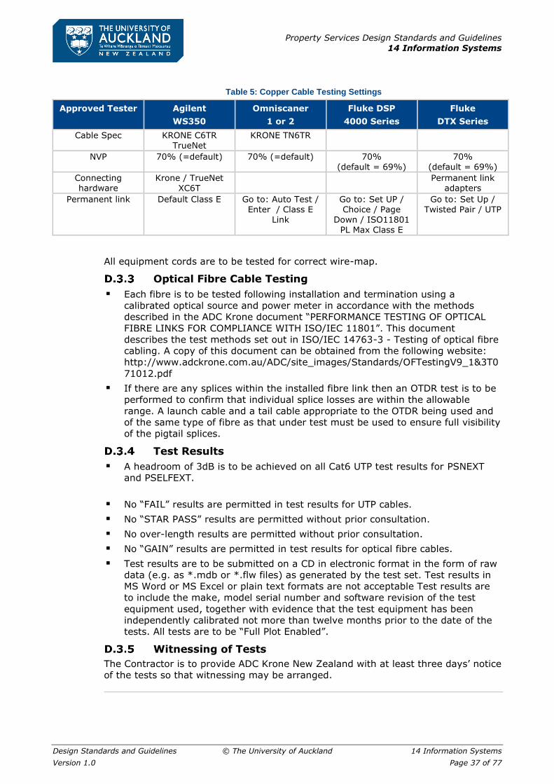
Property Services Design Standards and Guidelines
14 Information Systems
Design Standards and Guidelines © The University of Auckland 14 Information Systems
Version 1.0 Page 37 of 77
Table 5: Copper Cable Testing Settings
Approved Tester Agilent
WS350
Omniscaner
1 or 2
Fluke DSP
4000 Series
Fluke
DTX Series
Cable Spec KRONE C6TR TrueNet
KRONE TN6TR
NVP 70% (=default) 70% (=default) 70% (default = 69%)
70% (default = 69%)
Connecting hardware
Krone / TrueNet XC6T
Permanent link adapters
Permanent link Default Class E Go to: Auto Test / Enter / Class E
Link
Go to: Set UP / Choice / Page
Down / ISO11801 PL Max Class E
Go to: Set Up / Twisted Pair / UTP
All equipment cords are to be tested for correct wire-map.
Optical Fibre Cable Testing
▪ Each fibre is to be tested following installation and termination using a
calibrated optical source and power meter in accordance with the methods
described in the ADC Krone document “PERFORMANCE TESTING OF OPTICAL
FIBRE LINKS FOR COMPLIANCE WITH ISO/IEC 11801”. This document
describes the test methods set out in ISO/IEC 14763-3 - Testing of optical fibre
cabling. A copy of this document can be obtained from the following website:
http://www.adckrone.com.au/ADC/site_images/Standards/OFTestingV9_1&3T0
71012.pdf
▪ If there are any splices within the installed fibre link then an OTDR test is to be
performed to confirm that individual splice losses are within the allowable
range. A launch cable and a tail cable appropriate to the OTDR being used and
of the same type of fibre as that under test must be used to ensure full visibility
of the pigtail splices.
Test Results
▪ A headroom of 3dB is to be achieved on all Cat6 UTP test results for PSNEXT
and PSELFEXT.
▪ No “FAIL” results are permitted in test results for UTP cables.
▪ No “STAR PASS” results are permitted without prior consultation.
▪ No over-length results are permitted without prior consultation.
▪ No “GAIN” results are permitted in test results for optical fibre cables.
▪ Test results are to be submitted on a CD in electronic format in the form of raw
data (e.g. as *.mdb or *.flw files) as generated by the test set. Test results in
MS Word or MS Excel or plain text formats are not acceptable Test results are
to include the make, model serial number and software revision of the test
equipment used, together with evidence that the test equipment has been
independently calibrated not more than twelve months prior to the date of the
tests. All tests are to be “Full Plot Enabled”.
Witnessing of Tests
The Contractor is to provide ADC Krone New Zealand with at least three days’ notice
of the tests so that witnessing may be arranged.

Property Services Design Standards and Guidelines
14 Information Systems
Design Standards and Guidelines © The University of Auckland 14 Information Systems
Version 1.0 Page 38 of 77
Appendix E Specification for Horizontal Cabling
E.1 General
Refer to the Preliminaries section of the Specifications and to the General and Special
Conditions of Contract, which are equally binding on all trades.
E.2 Description of Works
The telecommunications services works comprises the provision of a fully engineered
structured cabling system as described herein and as shown on the drawings.
E.3 Materials Supply
Termination Hardware
The cable termination hardware shall be supplied by the contractor and shall comprise
only Krone manufactured items.
Cabinets, Racks and Boxes
The University may supply the racks or cabinets to be used in the installation and in
that case upon confirmation by the Engineer of the quantities required the units will
be available for collection from the IT Centre, 24 Symonds Street, after ten working
days’ notice of the requirement has been given to the Network Engineering Manager,
ITS, prior to collection.
UTP 4-pair Cables
All cable used in the installation is to be provided by the telecommunications service’s
contractor. However, to ensure that an ADC Krone 20/20 system performance
warranty is obtained for the works, The University of Auckland has entered into an
agreement with ADC Krone New Zealand for the supply of all data type copper cables
including the following:
▪ ADC Krone 4-pair UTP cable, Cat 6,TrueNet (TN6TMT-GY11B)
It is a condition of this agreement that all such cable used for The University of
Auckland installations must be of ADC Krone manufacture.
Optical Fibre Cables
Optical fibre cables used in the works may be of ADC Krone manufacture if readily
available, so that these links may be included in the 20/20 warranty test and
certification programme.
Other Cables
All cables other than 4-pair UTP cables and optical fibre cables used in the works (e.g.
multi-pair cables for voice) may be purchased from other manufacturers, provided
they are compliant with the relevant clauses in E.5 Cables on page 39.
Other Materials
The telecommunications services contractor shall supply all other hardware, materials
and incidentals necessary for the proper completion of the telecommunications
services works.

Property Services Design Standards and Guidelines
14 Information Systems
Design Standards and Guidelines © The University of Auckland 14 Information Systems
Version 1.0 Page 39 of 77
E.4 Standards
AS/NZS Standards
Unless otherwise specified all work shall be in accordance with the preferred practices
specified in AS/NZS 3080:2003 and associated documents, AS/NZS 3084:2003,
AS/NZS 3085.1:2004, AS/NZS 3087.1:2003 and AS/ACIF S009:2006.
Electrical Safety
In accordance with AS/NZS 3080:2003 Clause ZA.3.1, all work must satisfy the
minimum segregation requirements specified in AS/NZS 3000:2007 and AS/ACIF
S009:2006.
Particular attention must be taken to ensure compliance with:
▪ AS/NZS 3000:2007, Clause 1.5.11.5 Fundamental principles, Protection against
abnormal voltages, Different circuits and installations,
▪ AS/NZS 3000:2007, Clause 3.9.8, Selection and installation of wiring systems,
Installation requirements, Prevention of mutual detrimental effects between
services, AS/ACIF S009:2006, Clause 5.9, Cable terminations,
▪ AS/ACIF S009:2006, Clause 9.1, Separation from LV power or HV circuits
▪ AS/ACIF S009:2006, Clause 16.3, Separation from LV power cables
▪ AS/ACIF S009:2006, Clause 16.4, Separation from HV circuits,
▪ AS/ACIF S009:2006, Clause 18, Underground cabling.
Manufacturer’s Standards
All cabling is to be installed in accordance with the manufacturer’s requirements for
certification and for the provision of an ADC Krone 20/20-year system performance
warranty.
E.5 Cables
Four-pair Horizontal Copper Cables
Cable pairs shall meet Category 6 (Class E) requirements as specified in AS/NZS
3080:2003.
E.6 Cable Terminations
Copper cables are to be terminated on distributors using Krone Highband Ultim8 8-
pair modules installed on ADC Krone Profil 66-way backmounts on wall mounted
backing boards or on Krone HighBand 25 modules as required in the drawings and
schedules.
For details of distributors, backing boards and backmounts refer to Appendix B
Specification for Backbone Cabling on page 25. Where Local Cabinets are used the
cables are to be terminated on patch panels and Krone modules as described in the
Telecommunications Services Specification for Local Cabinets.
For all new work the patch panel outlets and work area outlets are to use the pair
assignment (pin-out) T568A as shown in AS/NZS3080:2003 Figure ZA.2(a).

Property Services Design Standards and Guidelines
14 Information Systems
Design Standards and Guidelines © The University of Auckland 14 Information Systems
Version 1.0 Page 40 of 77
E.7 Double-ended Patch Cables
All double-ended patch cables and jumpers will be supplied and installed by the
University and are therefore not included in this contract.
E.8 Catenary Installation
Wherever not more than 32 four- pair UTP cables are to be installed on a route in an
enclosed space then a catenary wire shall be used for cable support. Catenaries shall
be of at least 14-gauge high tensile galvanized steel insulated wire.
Catenaries shall be securely anchored at each end and well tensioned using
galvanized or plated steel turnbuckles, Hayes or Donalds style ratchet wire strainers.
They shall not be end-fixed to partition walls of timber or steel stud construction. All
anchors fixed into concrete, brickwork or blockwork shall use expansion fixings such
as Rawlbolts or Dynabolts, which should be set at right angles to the catenary.
Catenaries shall be run parallel to the major axes of the building and should not
deviate unless it is necessary to maintain specified clearance from other services.
Hangers shall be used to support catenaries at intervals of not more than 3 metres.
They shall be positioned to clear all other services and the ceiling by at least 300mm.
Each catenary wire is to be bonded to a common earth point at a conveniently located
distribution board.
E.9 Cable Tray Installation
Wherever more than 32 Cat6 four- pair UTP cables are to be installed on a route in
an enclosed space then a cable tray shall be used for cable support. However, in
situations where the installation of a tray would be difficult, multiple catenaries may
be installed, but each must support not more than two bundles of 32 cables.
Cable trays shall be in accordance with Appendix C Specification for Cable Trays and
Troughing on page 32.
Mesh trays, J-hooks or saddles are not be used.
E.10 Earthing
All catenaries, cable trays, cabinets and racks are to be bonded to a common earth
busbar at the nearest main electrical distribution board using 6 sq. mm earth wires
with green/yellow PVC insulation. These cables are to be securely bolted to bare metal
faces using crimp lugs and star washers.
For new installations install a brass earth busbar with 10 screw terminals and one
stud, in accordance with AS/NZS 3000:2007, clause 5.6.2.7. It shall be located at the
electrical distribution board and installed in a plastic box clearly labelled
“COMMUNICATIONS EARTH – DO NOT DISCONNECT”.
The main earth wire bonding the common earth busbar stud to the distribution board
electrical earth shall be of 16 sq. mm with green/yellow PVC insulation.

Property Services Design Standards and Guidelines
14 Information Systems
Design Standards and Guidelines © The University of Auckland 14 Information Systems
Version 1.0 Page 41 of 77
E.11 Cable Installation
Installation practices shall conform to these guidelines and those given in AS/NZS
3080:2003 as well as those required by the manufacturer. ADC Krone requires that
the “Random lay” method is used for all Cat6 and Cat6A cables installed.
Telecommunications cables should be physically segregated from all other services or
separated from them by at least 300mm throughout, except for the last 6 metres of
cable at the outlet end where the minimum separation may be reduced to 50mm.
Separation from electrical services shall be in accordance with AS/NZS 3000.
Cat6 cables should be secured neatly to catenaries and cable trays in bundles of not
more than 32 cables with Velcro cable ties or binders fixed at intervals of not more
than 400mm. Binders shall be at least 4mm wide and shall not be so tight as to cause
damage or distortion to the cable sheaths. Not more than thirty-two 4-pair UTP cables
are to be attached to one catenary wire. Cables are not to be exposed in areas with
open ceilings, but must be installed within enclosed ducts, trunking or raceways for
protection.
Cables are to be installed without tension. Particular care is to be taken at bends on
cable trays where cables must be installed so that they follow smoothly the radius of
the bend and do not pull against the inner edge of the bend or ride up over the side
of the tray.
Cat6 UTP cables shall be installed in a single length of between 10 and 90 metres
without joint. In cases where the total length of the work area cord, patch cord and
equipment cord exceed 10 metres, the maximum length of the horizontal cabling is
to be reduced accordingly.
Cables shall be installed with as large a bend radius as reasonably practical, but in no
case shall the bend radius be less than four times the outside diameter of the cable.
The minimum bend radius for 4-pair cables after installation shall be not less than
50mm, as required by AS/NZS 3080:2003, clause 9.2.2.2. ADC Krone also requires
that the minimum bend radius after installation shall be not less than 50mm.for Cat6A
cables and 25mm for Cat6 cables.
Cables shall be concealed within walls and ceilings wherever possible. Cables shall be
separated by at least 300mm from fluorescent light fittings and other sources of
electrical noise. Cables shall be separated by at least 300mm from low voltage
electrical cabling unless a suitable barrier or divider is provided.
Cables shall be run vertically within walls, deviating no more than 25mm from a
straight line.
Holes through plates and dwangs are to be at least 20mm in diameter.
Where horizontal runs within walls are necessary then the cable shall be installed
within 300mm of floor level and shall deviate not more than 25mm from a horizontal
line. Holes through studs shall be at least 20mm in diameter.
Where wiring cannot be concealed within walls and surface wiring is unavoidable the
Engineer must be consulted before work proceeds. Surface-run cables shall be
concealed in Neatcap or similar capping installed in a corner or against a doorframe
to make the installation as inconspicuous as possible. Staples shall not be used for
fixing cables to surfaces.
Any new trunking to be installed should use an approved product with two separate
compartments for telecommunications and electrical cables, and separate lids or lid
sections for each service:
▪ Interserv 180/2 and 150/2 Cat6 Trunking
▪ Modempak Cat6 Skirting Trunking

Property Services Design Standards and Guidelines
14 Information Systems
Design Standards and Guidelines © The University of Auckland 14 Information Systems
Version 1.0 Page 42 of 77
▪ Unistrut TD180 and TD155 Cat6 Skirting Duct
The trunking should be in colour grey, cream or beige unless otherwise specified.
Telecommunications outlets should be installed on the upper compartment of the
trunking using bezels, architrave or worktop style faceplates. Where required,
sections of the same trunking should be used for vertical droppers from the ceiling.
Where cables are installed in trunking the initial cable fill is not to exceed 40%.
Where cables pass through holes in structures the edges of the holes must be
smoothed or bushed with securely fitted plastic bushes.
All penetrations through firewalls and floors that are used for the installation of cables,
whether they are new or existing penetrations are to be sealed with a proprietary
intumescent fire-stopping compound or Firepro fire pillows immediately after the
installation of the cables has been completed.
The requirements and special considerations for cabling and pathways within
furniture, demountable partitions, workstation clusters, reception desks, printer
stations and the like are covered in the Telecommunications Services Specification
for Pathways in Furniture.
E.12 Telecommunications Outlet Installation
General
Outlets are to be installed in flush boxes mounted either horizontally or vertically as
specified. These are normally positioned at either 300mm or 1200mm above floor
level and must be coordinated with, and segregated from, adjacent electrical socket
outlets. Adjacent telecommunications and electrical outlet plates should be spaced
horizontally at 100mm centres on the same level and separated by a wall stud.
For all new work the telecommunications outlet sockets are to use the pair assignment
(pin-out) T568A as shown in AS/NZS3080:2003 Figure ZA.2(a).
The manufacturer’s requirements for maximum pair untwist and sheath stripping
lengths shall be strictly observed.
Special Requirements
In laboratories and wet areas special outlet arrangements using trunking, service
poles, ceiling mounted outlets or droppers may be specified. Installation details will
be shown on the drawings.
Outlets in Furniture
The special considerations relating to the installation of outlets within furniture,
demountable partitions, workstation clusters, reception desks, printer stations and
the like are covered in Appendix G Specification for Pathways in Furniture on page
50.
E.13 As-Built Documentation and Testing
Documentation
As-built documentation is to be prepared and submitted in accordance with the
requirements of the Telecommunications Services Specification for Documentation
and Testing.

Property Services Design Standards and Guidelines
14 Information Systems
Design Standards and Guidelines © The University of Auckland 14 Information Systems
Version 1.0 Page 43 of 77
Testing
Testing is to be carried out in accordance with the requirements of Appendix D
Specification for Documentation and Testing on page 35.
E.14 Labelling
Identifiers
The numbering scheme for record and database purposes for all items relating to the
cabling network is described in the document “Telecommunications Administration
Identifiers”, on page 67.
A copy of this document can be obtained on request from the Network Engineering
Manager, ITS, The University of Auckland.
Labelling
All telecommunications cable terminations, hardware and equipment installed under
the contract are to be permanently and neatly labelled as required in Appendix F
Specification for Labelling on page 44.

Property Services Design Standards and Guidelines
14 Information Systems
Design Standards and Guidelines © The University of Auckland 14 Information Systems
Version 1.0 Page 44 of 77
Appendix F Specification for Labelling
F.1 General
Administration identifiers
The format of administration identifiers used for the cable network of The University
of Auckland is set out in the document” Telecommunications Administration
Identifiers” on page 67.
A copy of the document can also be obtained on request from The University of
Auckland, ITS, Network Engineering Manager.
This is based on the considerations in AS/NZS 3085.1:2004, 5.3, and ANSI/TIA/EIA
606A, Administration Standards for Telecommunications Infrastructure.
Information to be shown
The information to be shown on labels is generally either the full administration
identifier or a part of the identifier, as detailed in F.3 Labelling Rules on page 45.
F.2 Requirements for Labels
Visibility
The size, colour and contrast between lettering and background must be selected so
that the identifier can be easily read. Labels shall generally have black characters at
least 3mm high (i.e. a font of at least 14 point) on a white background unless specified
otherwise. All labels shall be generated by a printing machine or engraving machine
using a common font such as “Arial” and not handwritten.
Durability
Labels shall be resistant to the environmental conditions, such as heat, moisture or
ultraviolet light, at the point of installation. They shall have a design life of at least
20 years.
Colour Coding of Distributor Fields
Colour-coding of termination fields can simplify administration by making the
structure of the layout more obvious. The labels to be used for distributor fields shall
be of different colours as follows:
Table 6: Distributor fields colour coding
Termination Type Colour Typical Application
Demarcation point Orange PSTN exchange connection
Network connection Green User side of PSTN exchange connection
Common equipment Purple PBX, switches, LAN equipment, servers, multiplexers.
Telephone system Red Key telephone or sub-PBX system
Campus backbone Brown Inter-building cabling
Building backbone 1st level White Equipment Room to Telecommunications Room
Building backbone 2nd level Grey Telecommunications Room to Telecommunications Room
Horizontal Blue Horizontal cabling terminated in Telecommunications Room
Other Yellow Alarms, security, BMS, A/V

Property Services Design Standards and Guidelines
14 Information Systems
Design Standards and Guidelines © The University of Auckland 14 Information Systems
Version 1.0 Page 45 of 77
Work to be included
Labels for all distributors, racks, cabinets, verticals, terminations and cables installed
under the contract shall be supplied and installed by the contractor.
There are no telecommunications labelling requirements for campus sectors or
buildings. These are covered by wayfinding and signage systems installed by Property
Services.
Door labels for Equipment Rooms and Telecommunications Rooms will normally be
supplied and installed by Property Services
There are no telecommunications labelling requirements for cable pathways.
F.3 Labelling Rules
Telecommunications Spaces
Equipment Rooms
A Traffolyte (black on white) or other suitable door label shall be fixed to the
Equipment Room Door with this form:
AAA.BBB
Telecommunications Equipment
Room
ER-CCC.DDE
Where:
▪ AAA = building number
▪ BBB = room number
▪ ER = “Equipment Room”
▪ CCC = building number
▪ DD = floor number (with leading zero)
▪ E = serial letter (usually “A”) assigned by ITS.
The label shall be made using letters at least 20mm high.
Example of a Telecommunications Equipment Room door label:
730.115
Telecommunications Equipment Room
ER-730.01A
Telecommunications Rooms
A Traffolyte (black on white) or other suitable door label shall be fixed to the
Telecommunications Room Door with this form:
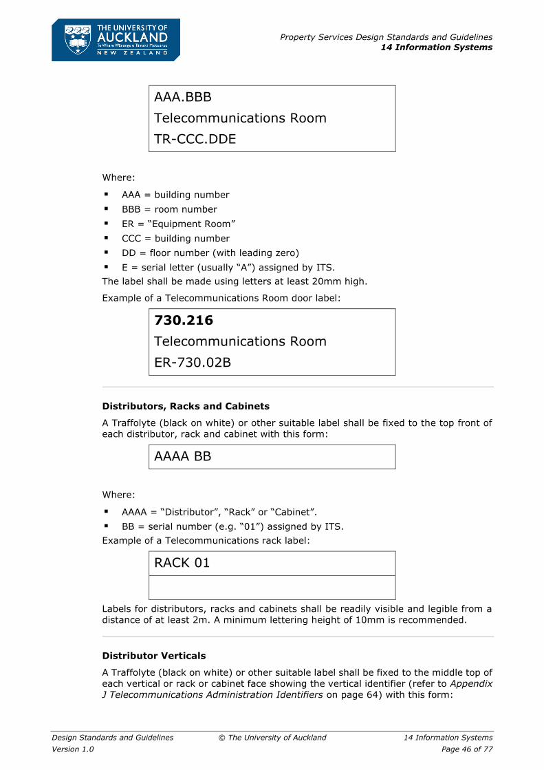
Property Services Design Standards and Guidelines
14 Information Systems
Design Standards and Guidelines © The University of Auckland 14 Information Systems
Version 1.0 Page 46 of 77
AAA.BBB
Telecommunications Room
TR-CCC.DDE
Where:
▪ AAA = building number
▪ BBB = room number
▪ ER = “Equipment Room”
▪ CCC = building number
▪ DD = floor number (with leading zero)
▪ E = serial letter (usually “A”) assigned by ITS.
The label shall be made using letters at least 20mm high.
Example of a Telecommunications Room door label:
730.216
Telecommunications Room
ER-730.02B
Distributors, Racks and Cabinets
A Traffolyte (black on white) or other suitable label shall be fixed to the top front of
each distributor, rack and cabinet with this form:
AAAA BB
Where:
▪ AAAA = “Distributor”, “Rack” or “Cabinet”.
▪ BB = serial number (e.g. “01”) assigned by ITS.
Example of a Telecommunications rack label:
RACK 01
Labels for distributors, racks and cabinets shall be readily visible and legible from a
distance of at least 2m. A minimum lettering height of 10mm is recommended.
Distributor Verticals
A Traffolyte (black on white) or other suitable label shall be fixed to the middle top of
each vertical or rack or cabinet face showing the vertical identifier (refer to Appendix
J Telecommunications Administration Identifiers on page 64) with this form:
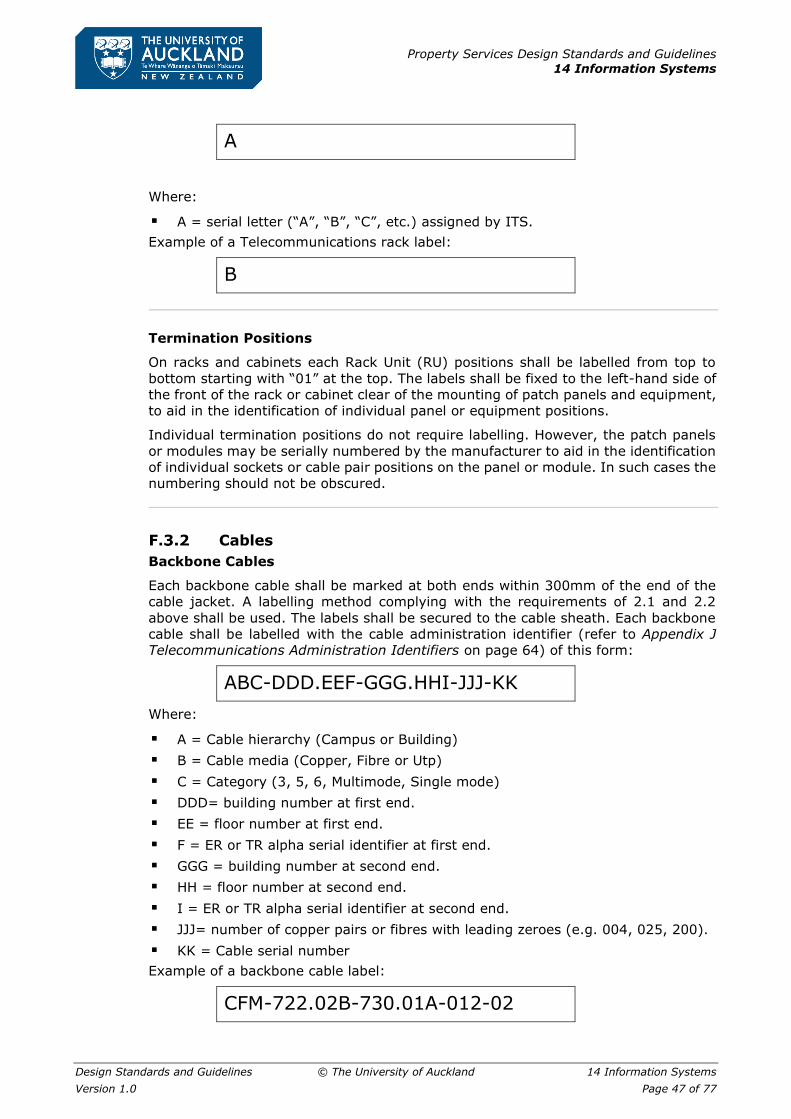
Property Services Design Standards and Guidelines
14 Information Systems
Design Standards and Guidelines © The University of Auckland 14 Information Systems
Version 1.0 Page 47 of 77
A
Where:
▪ A = serial letter (“A”, “B”, “C”, etc.) assigned by ITS.
Example of a Telecommunications rack label:
B
Termination Positions
On racks and cabinets each Rack Unit (RU) positions shall be labelled from top to
bottom starting with “01” at the top. The labels shall be fixed to the left-hand side of
the front of the rack or cabinet clear of the mounting of patch panels and equipment,
to aid in the identification of individual panel or equipment positions.
Individual termination positions do not require labelling. However, the patch panels
or modules may be serially numbered by the manufacturer to aid in the identification
of individual sockets or cable pair positions on the panel or module. In such cases the
numbering should not be obscured.
Cables
Backbone Cables
Each backbone cable shall be marked at both ends within 300mm of the end of the
cable jacket. A labelling method complying with the requirements of 2.1 and 2.2
above shall be used. The labels shall be secured to the cable sheath. Each backbone
cable shall be labelled with the cable administration identifier (refer to Appendix J
Telecommunications Administration Identifiers on page 64) of this form:
ABC-DDD.EEF-GGG.HHI-JJJ-KK
Where:
▪ A = Cable hierarchy (Campus or Building)
▪ B = Cable media (Copper, Fibre or Utp)
▪ C = Category (3, 5, 6, Multimode, Single mode)
▪ DDD= building number at first end.
▪ EE = floor number at first end.
▪ F = ER or TR alpha serial identifier at first end.
▪ GGG = building number at second end.
▪ HH = floor number at second end.
▪ I = ER or TR alpha serial identifier at second end.
▪ JJJ= number of copper pairs or fibres with leading zeroes (e.g. 004, 025, 200).
▪ KK = Cable serial number
Example of a backbone cable label:
CFM-722.02B-730.01A-012-02
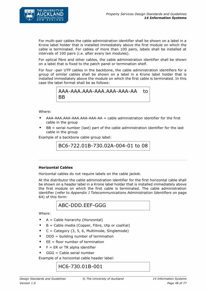
Property Services Design Standards and Guidelines
14 Information Systems
Design Standards and Guidelines © The University of Auckland 14 Information Systems
Version 1.0 Page 48 of 77
For multi-pair cables the cable administration identifier shall be shown on a label in a
Krone label holder that is installed immediately above the first module on which the
cable is terminated. For cables of more than 100 pairs, labels shall be installed at
intervals of 100 pairs (i.e. after every ten modules).
For optical fibre and other cables, the cable administration identifier shall be shown
on a label that is fixed to the patch panel or termination shelf.
For four -pair UTP cables in the backbone, the cable administration identifiers for a
group of similar cables shall be shown on a label in a Krone label holder that is
installed immediately above the module on which the first cable is terminated. In this
case the label format shall be as follows:
AAA-AAA.AAA-AAA.AAA-AAA-AA to BB
Where:
▪ AAA-AAA.AAA-AAA.AAA-AAA-AA = cable administration identifier for the first
cable in the group
▪ BB = serial number (last) part of the cable administration identifier for the last
cable in the group
Example of a backbone cable group label:
BC6-722.01B-730.02A-004-01 to 08
Horizontal Cables
Horizontal cables do not require labels on the cable jacket.
At the distributor the cable administration identifier for the first horizontal cable shall
be shown on a header label in a Krone label holder that is installed immediately above
the first module on which the first cable is terminated. The cable administration
identifier (refer to Appendix J Telecommunications Administration Identifiers on page
64) of this form:
ABC-DDD.EEF-GGG
Where:
▪ A = Cable hierarchy (Horizontal)
▪ B = Cable media (Copper, Fibre, Utp or coaXial)
▪ C = Category (3, 5, 6, Multimode, Singlemode)
▪ DDD = building number of termination
▪ EE = floor number of termination
▪ F = ER or TR alpha identifier
▪ GGG = Cable serial number
Example of a horizontal cable header label:
HC6-730.01B-001

Property Services Design Standards and Guidelines
14 Information Systems
Design Standards and Guidelines © The University of Auckland 14 Information Systems
Version 1.0 Page 49 of 77
Where the horizontal cable terminations extend over more than one vertical, a similar
label holder is to be installed at the top of the second and subsequent verticals
labelled with the cable administration identifier of the first cable terminated in that
vertical.
For all horizontal cables that are terminated on Krone modules a mini-label shall be
fixed to the top half of each module showing the following information for each cable
terminated:
EEF-GGG
Where:
▪ EEE = floor number of termination (ER, TR or LC)
▪ F = ER or TR alpha identifier
▪ GGG = Horizontal cable serial number
Example of a horizontal cable mini-label:
01B-127 01B-128
Telecommunications Outlets
At the telecommunications outlet the cable administration identifier for each
horizontal cable shall be shown on a label associated with the outlet. The following
information shall be shown for each terminated outlet:
EEF-GGG
Where:
▪ EE = floor number of termination
▪ F = ER or TR alpha identifier
▪ GGG = Horizontal cable serial number
Example of a telecommunications outlet label:
01B-127
Property Services Design Standards and Guidelines
14 Information Systems
Design Standards and Guidelines © The University of Auckland 14 Information Systems
Version 1.0 Page 50 of 77
Appendix G Specification for Pathways in
Furniture
G.1 Design
Introduction
This Specification deals with the design and specification of cabling pathways in
furniture, fixed and demountable partitions, workstation clusters, reception desks,
counters, printer stations and the like. It refers to the following Standards:
▪ AS/ACIF S009:2006
▪ AS/NZS 3000:2007
▪ AS/NZS 3080:2003
▪ AS/NZS 3084:2003
▪ AS HB 29:2000
These standards apply to the design and installation of cabling pathways but they do
not generally make specific recommendations regarding the selection of design
options, nor do they mandate specific requirements for the dimensions of pathways
and spaces.
This specification sets out quantitative interpretations of the various requirements
that must be met to ensure that electrical safety, interference, mechanical protection,
environmental and other considerations that impact on the performance of the cabling
system are satisfied in accordance with the standards and manufacturers guidelines.
Coordination and exchange of information
Reference: AS/NZS 3084:2003, 7.6
Requirements:
The following information generally needs to be shared among the manufacturer,
customer, (consultant,) designer and installer (of open office furniture systems):
▪ The number, type and location of telecommunications outlets and electrical
outlets in each work area.
▪ The diameter and minimum bend radius (installed and during installation) of
each cable type.
▪ The strategy for connecting building pathways to furniture pathways, including
the number, placement and cross-sectional area of the required interfaces.
▪ Furniture pathway cross-sections and cable capacities.
▪ The number of work areas in each furniture cluster (7.6).
How this can be achieved
All of the parties identified above should consult together during the planning and
design stages of the project. In addition to furniture layouts, drawings of the furniture
modules should be prepared showing the outlets, cabling routes, facilities and
interfaces. Sufficient detail should be shown to enable confirmation that the
requirements of all parties will be met.

Property Services Design Standards and Guidelines
14 Information Systems
Design Standards and Guidelines © The University of Auckland 14 Information Systems
Version 1.0 Page 51 of 77
Notes
It is usually worthwhile to assemble a prototype workstation cluster early in the
project so that all parties can be satisfied that the requirements of this specification
are fully met.
Figure 2: Access to the telecommunications and electrical compartments
Figure 3: Trunking in the furniture

Property Services Design Standards and Guidelines
14 Information Systems
Design Standards and Guidelines © The University of Auckland 14 Information Systems
Version 1.0 Page 52 of 77
Typical Preferred Arrangement
This describes a typical preferred arrangement that meets all the requirements
identified in later sections of this specification.
▪ General configuration
▪ Cables should be reticulated in two-compartment trunking with separate lids
giving separate access to the telecommunications and electrical
compartments (see Fig 2).
▪ The telecommunications cabling should be run in the upper compartment.
▪ The trunking should be an integral part of the furniture or should be rigidly
fixed to the furniture at a height of between 300 and 600 above floor level
(see Figure 2).
▪ The furniture should be fixed to the floor.
▪ Suitable flat-bottomed cord management trays and holes should be
designed and supplied as part of the furniture to allow a safe and tidy
installation of cords between the outlets and computers and telephones on
the desktops.
▪ Type and size of trunking
▪ Cables should be reticulated in two-compartment trunking with a fixed
dividing barrier.
▪ If the barrier is a separate component, then it must be fixed in place with a
screw.
▪ The size of the trunking must allow for the bending radius requirements
(minimum 50 mm for Cat 6 UTP) to be met with a maximum 40% cable fill
at initial installation. Allowance must be made for the reduced cross section
at outlets, crossings and changes in direction.
▪ Trunking with a 50 x 100 compartment for telecommunications cables and a
50 x 50 compartment for electrical cables is considered to be suitable. This
will allow for up to 40 cables of 7mm diameter to be installed.
▪ Where trunking runs exceed 6 metres in length the dividing barrier should
include ferromagnetic material.
▪ Safety and segregation
▪ The interface between the concealed fixed wiring and the visible flexible
cords for both the electrical cabling system and the structured cabling
system should be located in the same vicinity. This greatly simplifies the
coordination issues.
▪ All electrical wiring shall be contained within rigid metal trunking.
▪ Trunking lids for the electrical compartment shall be firmly secured with
screws that prevent accidental, inadvertent or unauthorised access to the
wiring.
▪ The trunking and the barrier separating the two compartments must be
earthed.
▪ Telecommunications cables shall not pass through the same holes as
electrical cables.
▪ Cabling routes shall be selected so as to minimise crossings of services.

Property Services Design Standards and Guidelines
14 Information Systems
Design Standards and Guidelines © The University of Auckland 14 Information Systems
Version 1.0 Page 53 of 77
G.2 Fixed Cabling
Electrical Safety
Hazard from electrical contact
Reference: AS/NZS 3000:2007, 1.5.4
Requirements:
▪ Barriers and enclosures shall be firmly secured in place and shall have adequate
stability and strength. This means that covers, doors, panels, lids, etc must be
firmly fixed, not just engaged in place (1.5.4.4 (b)). This applies to spaces
within which the live terminals at the back of electrical socket outlets are
exposed.
▪ The opening of enclosures shall not be possible without the use of a key or tool
(1.5.4.4(b) (i)), or
▪ An interlocking device shall be fitted (1.5.4.4 (b) (ii), or
▪ An intermediate barrier shall be provided to prevent accidental contact with all
live parts when the barrier or enclosure (lid) is removed (1.5.4.4 (b) (iii).
How this can be achieved
In b) above the requirement relates to enclosures containing live parts, such as the
cavities which contain the exposed backs of electrical socket outlets. Such enclosures
must not be accessible without the use of special tools or keys to remove fixing screws
or unlock fittings. Care must be taken to ensure that such access is not possible from
the other side of the partition or cavity or by removal of a panel on the opposite side
of the ducting. A simple solution is to fit electrical outlets in suitable flush boxes (as
in d) above) or use surface mounting blocks with the electrical cable passing through
a bushed hole into the enclosure.
The use of an interlocking device is usually only economic for switchboard covers and
the like.
Notes
▪ Barriers and enclosures must have adequate stability and strength to withstand
any appreciable distortion that might be caused by the stresses likely to occur
in normal operation. Outlet plates should not be mounted directly on
composition board decorative panels, for example.
▪ Consideration should be given to external influences such as kicking in areas
near floor level or knocking by mobile equipment or furniture.
▪ In the context of the above Standard the term “enclosure” means any enclosed
space, including a wall cavity.
Separation and segregation from electrical services
Reference: AS/ACIF S009:2006, 9.1.2.2
AS/ACIF S009:2006, 16.3.
Requirements:
▪ The conductors and terminations of telecommunications cables shall not be
located within the same enclosure as the uninsulated terminations of LV cables
unless accidental access to the LV terminations by persons working on the
telecommunications conductors and terminations is prevented by effective
means (9.1.2.2).
▪ The conductors and terminations of telecommunications cables shall be
separated from single insulated conductors and terminations of LV cables by

Property Services Design Standards and Guidelines
14 Information Systems
Design Standards and Guidelines © The University of Auckland 14 Information Systems
Version 1.0 Page 54 of 77
either a minimum distance of 150mm or by means of a permanent, rigidly-fixed
barrier of durable insulating material or metal. If the barrier is metal, it shall be
connected to a protective earthing conductor via a minimum 2.5mm2
green/yellow insulated conductor (9.1.2.3).
▪ Telecommunications cables shall be permanently separated from LV cables by:
▪ a minimum distance of 50mm, or
▪ a barrier of durable insulating material or metal, or
▪ a timber or metal joist, stud, noggin or rafter of any thickness (16.3.1)
▪ Telecommunications cables shall not pass through the same hole as LV cables
where they are within 50mm of any securing face of the building framework,
irrespective of whether there is a barrier provided between the cables (16.3.2).
▪ Telecommunications cables which share ducting with LV cables shall be run in a
separate channel of the common ducting provided the channel is separated by a
fixed and continuous barrier of durable insulating material or metal (13.3.3).
How this can be achieved
It is considered best practice to run the telecommunications and LV cables in separate
channels and to mount the telecommunications outlets on separate panels or panel
sections from the electrical outlets so that the electrical cabling and terminals (at the
back of electrical outlets) are not disturbed or exposed when the telecommunications
outlets are removed for installation or maintenance purposes.
“Single –insulated conductors” in b) above includes the area at the back of an
electrical outlet where the outer sheath of the electrical cable is removed to allow for
termination of the individual wires. Since the standard University practice is to mount
telecommunications and electrical outlet plates 100mm apart, which is closer than
150mm apart, it follows that a barrier, as defined in e) above, must be provided.
“Permanently” separated in c) above means that the services must be fixed so that
they cannot sag or move in any way that would reduce the separation below 50mm.
Compliance with c).b above may be achieved by the enclosure of either the
telecommunications cable or the LV cable in suitable conduit. It is usually simpler and
cheaper to enclose the LV cable.
Separated routes and penetrations must be provided where cables pass from the
furniture or partitions into the building structure. The provision of a barrier, sleeve or
conduit within the same penetration is not acceptable.
“Permanent and rigidly fixed” in b) above and “Fixed and continuous” in e) above
mean that:
▪ The barrier must be an integral part of the ducting or remain permanently fixed
in place by screws, bolts or other locking fittings when covers are removed, and
must not be able to be dislodged.
▪ There must be no gaps or penetrations in the barrier. However, breaks in the
barrier are permitted at intersections of modular office furniture including
abutments to service columns, provided that: (a) these can be opened for
inspection, (b) cables do not cross into other channels, and (c) fixings are fitted
where required to maintain segregation at changes in direction of any cabling in
the ducting.
Notes
In the context of the above Standard the term “enclosure” means any enclosed space,
including a wall cavity.
Low voltage is defined in AS/NZS 3000:2007 as any voltage exceeding 50 V a.c. or
120 V d.c. but not exceeding 1,000 V a.c. or 1,500 V d.c. This includes 230-240 volt
single-phase and 230/400 volt three-phase electrical services.

Property Services Design Standards and Guidelines
14 Information Systems
Design Standards and Guidelines © The University of Auckland 14 Information Systems
Version 1.0 Page 55 of 77
The requirements for separation from high-voltage cables are covered in AS/ACIF
S009:2006, 16.4.
Separation and segregation from non-electrical services
Reference: AS/ACIF S009:2006, 9.2.2
Requirements:
Telecommunications cables, conductors and terminations shall be separated from
non-electrical hazardous services by a minimum distance of 100mm (9.2.2).
How this can be achieved
Care must be taken to ensure that telecommunications cable pathways do not pass
close to hazardous services such as gas or steam pipes and fittings.
Notes
A hazardous service includes any pipe containing corrosive or flammable liquid or gas
or any substance exceeding 60°C.
Earthing
Reference: AS/NZS 3000:2007, 3.9.4.4.
Requirement:
It is not mandatory in the Wiring Rules for metallic cable trunking or trays to be
earthed. However, there is provision in Section 3.9.4.4 (b) for the protection of wiring
concealed in walls by means of an earthed metallic enclosure. Further, it is prudent
to ensure that all exposed metalwork is bonded to the protective earth system to
provide protection against earth faults giving rise to hazardous potential differences.
Refer to AS/NZS 3000:2007, 5.6.7.2.
How this can be achieved
All metal enclosures, trunking, trays and catenary wires and parts thereof that are
used for the enclosure or support of cables or the mounting of electrical outlets should
be bonded to the protective electrical earth.
Notes
Only one earth connection should be made from each interconnected and bonded
system, and the connection should be made at the nearest electrical distribution
board.
Interference
Reference: AS/NZS 3080:2003, ZA.3.2.
Requirement:
To minimise coupling of noise and other interference between telecommunications
cabling and other electrical systems the following should be considered:
▪ Increased separation beyond mandatory requirements.
▪ Use of surge suppressors and other devices designed to limit electrical
transients in communications and electrical cabling and equipment.
▪ Use of enclosed, grounded, metallic ducting or conduit. The use of ferrous
materials may reduce induction.
Property Services Design Standards and Guidelines
14 Information Systems
Design Standards and Guidelines © The University of Auckland 14 Information Systems
Version 1.0 Page 56 of 77
▪ Ensuring that open or non-metallic telecommunications pathways do not closely
parallel potential noise sources such as electrical power wiring, radiofrequency
sources, inverters, induction heaters, arc welders, large motors and generators
(ZA.3.2).
How this can be achieved
It is considered good practice to either increase the separation beyond the mandatory
requirement or to use a barrier of ferrous material to reduce interference from
electromagnetic induction.
Notes
A steel conduit or trunking surrounding one service also serves the required purpose.
Pathway size
Reference: AS/NZS 3084:2003, 7.1.
Requirement:
The initial fill must not exceed 40% of the design capacity. This makes allowance for:
▪ The loose lay of cables without stresses being imposed by the pathway,
▪ Future cables (e.g. optical fibre to the desk) to be installed, and
▪ Bend radius requirements to be met at changes in direction of the pathway
(e.g. right-angled intersections.)
How this can be achieved
Calculation of the size of a pathway should be based upon the assumption that each
horizontal cable occupies an area of 49mm2. Thus, for example, let us assume that
we are designing a system that can have up to eight workstations in a cluster which
is cabled from one end. This requires three telecommunications outlets per
workstation; hence 24 horizontal cables need to be run. These cables will have a
cross-section of 24x49 = 1176mm2. The cross-section of the cable trough, duct or
channel must therefore be 2.5 times this area to allow for the 40% capacity factor,
or 2940mm2. This can be achieved using a channel that is, say, 50x60mm, or a tube
that is 65mm internal diameter.
Notes
This does not make any allowance for the cross-sectional area of the channel being
reduced by outlets or other intrusions into the channel. An outlet on a flush plate on
the front of the channel will limit the cabling capacity of the channel and an additional
allowance of 500mm2 must be added to the design. In the above case this would
require a channel of 50x70mm.
Cable bending radius
Reference: AS/NZS 3080:2003, 9.2.2.2.
Requirement:
The minimum bending radius (after installation) shall be not less than 25mm for four
pair cables with diameter up to 6mm. For the minimum bending radius during
installation (which may be greater), refer to the cable manufacturer’s
recommendations (9.2.2.2, Table 25, 1.5).
The minimum bending radius (after installation) shall be not less than 50mm for four
pair cables with diameter over 6mm. For the minimum bending radius during

Property Services Design Standards and Guidelines
14 Information Systems
Design Standards and Guidelines © The University of Auckland 14 Information Systems
Version 1.0 Page 57 of 77
installation (which may be greater), refer to the cable manufacturer’s
recommendations (9.2.2.2, Table 25, 1.5).
How this can be achieved
The telecommunications outlet on a flush outlet plate protrudes into the cabling
channel by up to 15mm. The cable exits from the back of the outlet, and hence must
curve through an arc of 90 degrees to run longitudinally along the back of the channel.
This means that either:
▪ The channel must be at least 65mm deep, measured from the front face, or
▪ In the case of a double-sided channel with a central division, penetrations are
made in the division to allow the cable to laid in correctly, or
▪ If a shallower channel is used a mounting block may be used to move the outlet
plate forward, proud of the surface of the channel by a distance equal to the
difference between the channel depth and 65mm, or
▪ The outlet plate may be mounted in a standard flush box or surface mounting
block with a depth of 65mm adjacent to the channel.
Notes
The manufacturer’s recommended minimum cable bending radius for pulling-in of
cables is usually greater than the installed minimum radius (refer to the table in AS
HB29:2000, 4.2.3). Generally, it is necessary to use channels with removable lids or
covers so that cables can be laid-in and not pulled-in around right-angled bends.
Cat6 UTP cables are generally more than 6mm in diameter, hence the 50mm bending
radius limit applies for all installations where Cat6 cables are to be installed. Since
the University has standardised on Cat6 cable for all new work, this higher bending
radius applies to all new furniture and fittings.
Mechanical Protection
Reference: AS/ACIF S009:2006, 5.4
Requirement:
All parts of an installation shall be adequately protected against damage which might
reasonably be expected to result from mechanical injury (5.4).
Conduits, trays and trunking shall have all sharp edges removed from their cable
bearing surfaces (5.4).
How this can be achieved
The types of cables used in telecommunications cabling systems are not robust in
that they do not have rugged sheaths or armouring. Particular care should be taken
to provide durable protection for cables that run from the floor, wall or ceiling into
modular furniture.
Any furniture module that contains fixed outlets and fixed wiring shall be secured in
place so that it cannot be moved in normal use. Such movement could damage the
insulation of electrical or telecommunications cables and present a hazard to users.
Furniture modules shall be bolted or screwed to the floor or adjoining wall. If this is
not practicable, then the outlets should be installed in a floor box or wall outlet plate
and cords used to connect the services to the work area equipment.
Cables that run from floor penetrations, floor troughing or floor boxes up into furniture
must be protected by suitably robust rigid trunking. Experience has shown that
flexible trunking systems or conduit are not sufficiently durable for this purpose.

Property Services Design Standards and Guidelines
14 Information Systems
Design Standards and Guidelines © The University of Auckland 14 Information Systems
Version 1.0 Page 58 of 77
Sharp edges on trunking or cable trays that are inherent in the design or result from
sharp changes in direction must be smoothed and rounded or protected by suitable
sleeves or grommets that are fixed in place so that they cannot easily be dislodged.
Notes
Telecommunications and electrical outlets under workstation desks should generally
be installed at a height of at least 450mm above floor level so that they are out of
the zone where they are likely to be kicked.
G.3 Flexible Work Area Cords
Separation and segregation
Reference: AS/ACIF S009:2006, 16.3.1.
Requirement:
Flexible work area equipment cords and electrical appliance cords are not required to
be separated unless installed as fixed or concealed wiring (16.3.1, Note 3).
How this can be achieved
Do not fix or conceal work area cords.
Notes:
It is good practice to use an open cable management tray fitted beneath the desktop
to safely stow surplus length of work area cords and keep them tidy. Trays made
from sheet metal are preferred. Cords can be run from this cable management system
through bushed access holes in the desktop to the terminal equipment.
Length of work area cords
Reference: AS/NZS 3080:2003, 7.2.2.2
Requirement:
Work area cords should not exceed 3 metres in length (refer to Notes below).
How this can be achieved
If any terminal equipment in a cluster is more than 3 metres from a wall outlet or
floor box then the furniture must be fixed in place and the telecommunications outlet
installed at or on the workstation at a point less than 3 metres from the terminal
equipment, with concealed, separated or segregated fixed cabling to the floor
distributor.
Notes
Horizontal cable link design is based on a fixed cable length of not more than 90
metres, plus a combined equipment cord + jumper + work area cord length of not
more than 10 metres. Up to 7 metres is allowed for equipment cords and jumper
cables in the telecommunications room.
Hence, in order to comply with the 100 metre limit of the standard, each work area
cord must not exceed 3 metres.

Property Services Design Standards and Guidelines
14 Information Systems
Design Standards and Guidelines © The University of Auckland 14 Information Systems
Version 1.0 Page 59 of 77
Appendix H Specification for Underground Ducts
H.1 General
Refer to the Preliminaries section of the Specifications and to the General and Special
Conditions of Contract, which are equally binding on all trades.
H.2 Description of Works
The telecommunications services work comprises the provision of an underground
telecommunications cable duct system as described herein and as shown on the
drawings. The cables will later be installed in the ducts as part of a separate cabling
contract.
H.3 Materials Supply
The contractor shall supply all materials and incidentals necessary for the proper
completion of the works.
H.4 As-Built Documentation
The contractor shall prepare by a plan showing the as-built route of the ducts, depth
of cover, duct formation and other detail. As -built drawings shall be appropriately
titled, identified, numbered and dated and shall include the name and address of the
contractor. The standard of preparation shall comply with NZS 5902 parts 0 to 5. A
symbol legend shall be provided. Information shown on the drawings shall be
compatible with labelled items on site. Room numbers shall be included on the
drawings.
Floor plans of existing buildings in AutoCAD version 14 are available from Facilities
Management for updating and including in the as-built documentation.
H.5 Duct Materials
The ducts are to be 100mm nominal diameter UPVC in accordance with NZS
7643:1969, Code of Practice for the Installation of UPVC Pipe Systems.
Where drilling or thrusting is used as a means of installation thick walled PE duct in
continuous lengths may be used.
The preferred colour for telecommunications ducts is white. Alternative colours may
be used provided they are not the same as any of the colours specified for hazardous
services:
Table 7: Duct colours for hazardous services
Colour Hazardous Service
Orange Electrical power
Yellow Fuel, process, toxic or medical gases
Silver steam
Brown Flammable and combustible liquids
Violet Acids and alkalis
Light blue Compressed air

Property Services Design Standards and Guidelines
14 Information Systems
Design Standards and Guidelines © The University of Auckland 14 Information Systems
Version 1.0 Page 60 of 77
H.6 Quantities
Within the campus, four 100mm ducts in square formation or three ducts in triangular
formation are to be installed in the main duct routes. Two ducts in horizontal
formation are to be installed for building entries. Minor lateral routes or off-campus
routes will generally comprise one 100mm duct.
H.7 Depth
On city Council road reserve, the cover is to be not less than 900 in carriageways and
600 in footways and elsewhere. A reduced cover of 450mm is permitted for building
entries. On University and private property, the cover is to be not less than 500. No
reduced cover shall be permitted without the written approval of the Engineer.
H.8 Protection and Warning Strip
All ducts shall have a white plastic warning strip or marking tape together with a 100
x 25 ground treated protection timber or similar protection installed 300 below ground
level and at least 100 above the top duct over the entire trenched length.
H.9 Backfilling
The trench is to be thoroughly compacted during backfilling in layers of not more than
100mm using a plate compactor.
H.10 Duct Bends
Significant changes of direction are to be achieved using pre-formed duct bends with
a radius of curvature of not less than 5 metres. At or within 500mm of a building
entrance or access pit the radius of curvature may be reduced to 800mm. Small
radius plumbing bends are not to be used.
There shall be no more than two 90° bends in any one pull length between pits.
H.11 Cable Pits
Cable handling pits of nominal internal size 1200x600x600 with one or two lockable
alloy lids are to be installed where building entry ducts branch off the main route. Pits
of nominal internal size 600x600x600 with one lockable alloy lid are to be installed
where the route changes direction by more than 90°. Where pits are installed in
driveways or road crossings care must be taken to ensure that they have an
appropriate design loading to withstand the passage of vehicles. Ducts are to be
sealed into the pits at the points of entry.
The exact position of each pit is to be confirmed on site by the Engineer.
H.12 Joints
All joints in PVC ducts are to be socketed and made watertight using PVC solvent
cement.

Property Services Design Standards and Guidelines
14 Information Systems
Design Standards and Guidelines © The University of Auckland 14 Information Systems
Version 1.0 Page 61 of 77
H.13 Building entries
The principal will identify and mark the building entry points. Concrete cutting of
penetrations through foundations or walls may be required using a masonry core drill
to produce a penetration 10mm greater than the duct OD.
The contractor shall be responsible for checking the condition of the structure,
avoiding any building services in the vicinity of the penetration and ensuring that the
penetration does not affect the structure or stability of the building.
The entry ducts are to be secured in place and sealed into the penetrations using a
non-hardening mastic compound.
H.14 Cleaning and Draw Wires
Upon completion each duct is to be tested and cleaned using compressed air and a
mandrel and swab to remove debris and a draw wire or non-elastic tape installed in
each duct from pit to pit or duct entry point. The finished ends of each duct are to be
sealed with a plug or suitable duct-stopping compound to prevent the ingress of
rodents, insects or debris.
H.15 Disturbance and reinstatement
The ducts are to be installed with minimum disturbance to adjacent trees, structures
and surfaces. The trench is to be hand dug within the drip line of trees to avoid root
damage. All hard surfaces are to be restored to their original condition. The University
will attend to the dressing and sowing of lawn areas and the replanting of gardens.
H.16 Maintenance
The installation contractor shall be responsible for making good any defects in the
installation, including repair of hard surfaces and subsidences, for a period of 12
months after practical completion.
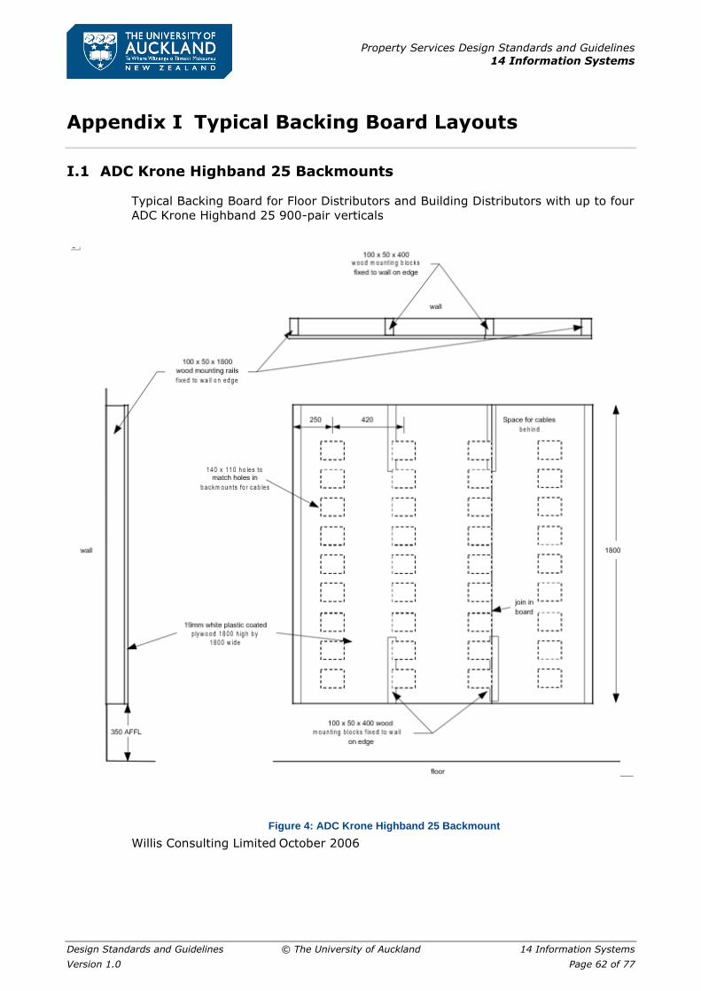
Property Services Design Standards and Guidelines
14 Information Systems
Design Standards and Guidelines © The University of Auckland 14 Information Systems
Version 1.0 Page 62 of 77
Appendix I Typical Backing Board Layouts
I.1 ADC Krone Highband 25 Backmounts
Typical Backing Board for Floor Distributors and Building Distributors with up to four
ADC Krone Highband 25 900-pair verticals
Figure 4: ADC Krone Highband 25 Backmount
Willis Consulting Limited October 2006

Property Services Design Standards and Guidelines
14 Information Systems
Design Standards and Guidelines © The University of Auckland 14 Information Systems
Version 1.0 Page 63 of 77
I.2 ADC Krone Profil Backmounts
Typical Backing Board for Floor Distributors and Building Distributors with up to eight
ADC Krone Profil 600-pair (66-way) verticals.
Figure 5: ADC Krone Profil Backmount
Willis Consulting Limited October 2006
Property Services Design Standards and Guidelines
14 Information Systems
Design Standards and Guidelines © The University of Auckland 14 Information Systems
Version 1.0 Page 64 of 77
Appendix J Telecommunications Administration
Identifiers
J.1 Overview
This document sets out the format of the administration identifiers to be used for the
telecommunications cabling system of the University of Auckland. It provides a
uniform approach that is appropriate to the size and scope of the network for the use
and benefit of the owners, end users, consultants, designers, contractors, suppliers,
installers, managers and administrators.
The purpose of these administration identifiers is to provide a key to finding the
recorded information within the administration system (whether it is a paper record,
simple spreadsheet or comprehensive computer database system). Each identifier
must be unique within a building.
It is expected that the use of these standard formats will increase the value of the
University’s investment in the infrastructure by reducing the cost of maintaining the
system, extending its economic life and increasing the efficiency of its use.
This document was originally published in 1997 but has been substantially revised to
bring it into line with current University terminology. In particular it has been updated
to conform to the definitions in AS/NZS 3080:2003. Where appropriate it has been
brought into line with the recommendations in the 2003 edition of ANSI/TIA/EIA
606A, Administration Standard for Telecommunications Infrastructure. This latter
North American Standard is likely to be used as a model for administration software
packages, and alignment with the recommended formats will greatly simplify the
introduction of enhanced, computer-based management of structured cabling system
infrastructure in the future by the University. It is also likely that the ISO and AS/NZS
standards bodies will follow the lead given by the ANSI Standard when revising their
own Standards. Not all of the identifiers recommended by ANSI/TIA/EIA 606A are
covered in this document. Indeed, it is unlikely that the University will ever need to
create formal records of earthing busbars or firestop locations.
This document should be treated as a guide, rather than a mandatory standard. It is
recognized that some existing identifiers for buildings, floors, and spaces such as
lobbies, corridors and stairwells do not comply strictly with these guidelines.
The information to be included on labels, and the colour coding of labels serve
separate purposes in that they need to convey additional information about the cable
or equipment. These requirements for labelling are covered in a separate ITS
document; “Specification for Labelling”.
J.2 Scope
The following tables set out in a simple format the essential information relating to
identifiers. The following information is provided in each case:
Name
This is the standard name of the item to be identified.
Format
This shows the format of the identifier, including separator symbols. The
characters used in the format are referred to in the following definition section.
Example

Property Services Design Standards and Guidelines
14 Information Systems
Design Standards and Guidelines © The University of Auckland 14 Information Systems
Version 1.0 Page 65 of 77
This gives a real example of an identifier that conforms to the format.
This specifies the types of characters that are permitted, and cross-references
other identifiers that form part of this identifier.
Range
This specifies the range of permitted values, and defines the meaning of specific
codes, such as campus sector codes.
Responsibility
This identifies the group within the University that is responsible for assigning and
managing the various identifiers.
The parts of the campus, buildings and cabling system that need to be identified are
as follows.
Spatial Information
Campus Sector
A campus sector is a collection of physically adjacent buildings and grounds that
form a separately identifiable part of the University. Campus sectors are identified
by numeric codes managed by Property Services.
Building
Each physically separate building requires a unique identifier. Buildings are
identified by a Building Number system administered by Property Services.
Workspace
A workspace is any area within which telecommunications outlets might be
installed at some time throughout the life of the system. All spaces are identified
by Room Numbers which are assigned and administered by Property Services.
Equipment Room (ER) or Telecommunications Room (TR)
A space set aside for the installation of telecommunications equipment and/or the
termination of telecommunications cables.
Cabling Information
Backbone Cabling
A campus backbone cable runs from an ER or TR in one building to an ER or TR in
another building. It is usually installed in an underground duct or tunnel. A building
backbone cable is run within the same ER or TS, or between one TS and another
within the same building. It is usually installed within a riser or on a cable tray.
Horizontal Cable and Telecommunications Outlet (TO)
Each horizontal cable from a TS to a telecommunications outlet, and the
associated TO itself, is uniquely identified. The definition includes all copper, UTP,
optical fibre and coaxial cables that are terminated in a work area.
Termination Hardware
This is used to identify a particular rack, cabinet or distributor within which a cable
is terminated, or equipment is installed.
Termination Position
This is used to identify the position within a rack, cabinet or distributor where a
particular cable is terminated, or equipment item is installed.

Property Services Design Standards and Guidelines
14 Information Systems
Design Standards and Guidelines © The University of Auckland 14 Information Systems
Version 1.0 Page 66 of 77
Pathway Information
Campus Pathway
A campus pathway is a service tunnel or underground duct providing a route
between two separate buildings for the installation of campus backbone cables.
Building Pathway
A building pathway is a riser or cable tray providing a route within a building for
the installation of building backbone cables.

Property Services Design Standards and Guidelines
14 Information Systems
Design Standards and Guidelines © The University of Auckland 14 Information Systems
Version 1.0 Page 67 of 77
J.3 Telecommunications Administration Identifiers
Explanation
In the format definitions:
▪ A = alpha character
▪ N = numeric character
▪ O = open format, alpha or numeric character.
▪ The “first” end for a campus backbone cable (inter-building) is the end with the
lesser building number.
▪ The “first” end for a building backbone cable (intra-building) is the end with the
lesser alphanumeric ER or TR identifier.
▪ The “second” end in each case is the other end.
▪ Each Equipment Room (ER) and Telecommunication Closet (TC) will usually
have a Room Number (e.g. 201.415A) as well as a corresponding ER or TC
Identifier (e.g. ER-201-04A).
Spatial Identifiers
Campus Sector
Format a
Example 2
Definition 1 character = (N) a = Campus Sector identifier
Range
1 = Library 2 = Arts 3 = Science
4 = Engineering 5 = FMHS 6 = Halls of Residence 7 = Tamaki 8 = Law
9 = global (all or many campus sectors)
Responsibility Property Services
Building
Format Abc = (NNN)
Example 201
Definition
3 characters = (NNN) a = Campus Sector identifier (see above)
bc = Serial number starting from 01 (with leading zero) unique to each campus sector
Range 100 to 999
Responsibility Property Services
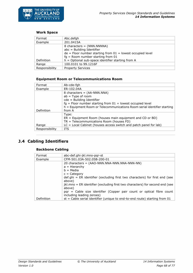
Property Services Design Standards and Guidelines
14 Information Systems
Design Standards and Guidelines © The University of Auckland 14 Information Systems
Version 1.0 Page 68 of 77
Work Space
Format Abc.defgh
Example 201.0415A
Definition
8 characters = (NNN.NNNNA) abc = Building Identifier
de = Floor number starting from 01 = lowest occupied level fg = Room number starting from 01 h = Optional sub-space identifier starting from A
Range 100.0101 to 99.1216F
Responsibility Property Services
Equipment Room or Telecommunications Room
Format Ab-cde-fgh
Example ER-102.04A
Definition
8 characters = (AA-NNN.NNA) ab = Type of room cde = Building Identifier
fg = Floor number starting from 01 = lowest occupied level h = Equipment Room or Telecommunications Room serial identifier starting from A
Range
Type:
ER = Equipment Room (houses main equipment and CD or BD) TR = Telecommunications Room (houses FD) LC = Local Cabinet (houses access switch and patch panel for lab)
Responsibility ITS
J.4 Cabling Identifiers
Backbone Cabling
Format abc-def.ghi-jkl.mno-pqr-st
Example CFM-501.03A-502.05B-200-01
Definition
20 characters = (AAO-NNN.NNA-NNN.NNA-NNN-NN) a = Hierarchy b = Media c = Category
def.ghi = ER identifier (excluding first two characters) for first end (see above)
jkl.mno = ER identifier (excluding first two characters) for second end (see above) pqr = Cable size identifier (Copper pair count or optical fibre count including leading zeroes) st = Cable serial identifier (unique to end-to-end route) starting from 01

Property Services Design Standards and Guidelines
14 Information Systems
Design Standards and Guidelines © The University of Auckland 14 Information Systems
Version 1.0 Page 69 of 77
Range
Hierarchy: B = building backbone C = campus backbone Media:
C = copper multi-pair F = optical fibre U = UTP four-pair X = coaxial Category: 3 = Category 3 cable 5 = Category 5 or 5E UTP
6 = Category 6 or 6A UTP A = audio-visual
B = BMS, security and alarm E = Ethernet (thick) M = multimode optical fibre S = singlemode optical fibre
T = Ethernet (thin)
Responsibility ITS
Horizontal cabling and telecommunications outlet
Format abc-def.ghi-jkl
Example HU6-501.03A--027
Definition
12 characters = (AAO-NNN.NNA-NNN) a = Hierarchy b = Media
c = Category
def.ghi = TR identifier (excluding first two characters) (see above) jkl = Cable serial identifier (unique to TR) starting from 001
Range
Hierarchy: H = horizontal
Media: C = copper multi-pair F = optical fibre U = UTP four-pair X = coaxial Category:
3 = Category 3 cable 5 = Category 5 or 5E UTP 6 = Category 6 or 6A UTP A = audio-visual
B = BMS, security and alarm E = Ethernet (thick) M = multimode optical fibre
S = singlemode optical fibre T = Ethernet (thin)
Responsibility ITS
Distributor Termination Hardware (cabinet, rack or frame)
Format abc-def.ghi-jkl
Example HU6-501.03A--027
Definition
12 characters = (AAO-NNN.NNA-NNN) a = Hierarchy
b = Media c = Category def.ghi = TR identifier (excluding first two characters) (see above) jkl = Cable serial identifier (unique to TR) starting from 001
Range
Hierarchy: H = horizontal Media: C = copper multi-pair

Property Services Design Standards and Guidelines
14 Information Systems
Design Standards and Guidelines © The University of Auckland 14 Information Systems
Version 1.0 Page 70 of 77
F = optical fibre U = UTP four-pair X = coaxial Category:
3 = Category 3 cable 5 = Category 5 or 5E UTP 6 = Category 6 or 6A UTP A = audio-visual B = BMS, security and alarm E = Ethernet (thick) M = multimode optical fibre
S = singlemode optical fibre T = Ethernet (thin)
Responsibility ITS
Termination Position
Format ab-cde.fgh-ij-klmno
Example TP-102.04A-01-A0905
Definition
15 characters = (AA-NNN-NNA-NN-ANNNN) ab = TP (Termination Position). cde.fgh-ij = Distributor termination hardware identifier (see above). k = Vertical identifier (serial column (vertical, cabinet or rack) identifier (counting from left to right). lm = Module identifier (serial row (module or RU) identifier (counting
from top to
bottom). no = Position identifier (serial pair or connector (position) identifier (counting from left to right, or as labelled).
Range
Vertical identifier:
A to Z Module identifier: 01 to 66 Position identifier: 01 to 48
Responsibility ITS
J.5 Pathway Identifiers
Campus Pathway
Format ab-cde.fgh-ijk.lmn-opq-rs
Example PW-501.03A-502.05B-DCT-01
Definition
19 characters = (NN-NNN.NNA-NNN.NNA-NNN-NN) ab = PW (PathWay) cde.fgh = ER identifier (excluding first two characters) for first end (see above) ijk.lmn = ER identifier (excluding first two characters) for second end (see above) opq = Type
rs = pathway serial identifier (unique to end-to-end route) starting from 01
Range
Type:
DCT = duct system
TRY = cable tray TUN = tunnel
Responsibility ITS

Property Services Design Standards and Guidelines
14 Information Systems
Design Standards and Guidelines © The University of Auckland 14 Information Systems
Version 1.0 Page 71 of 77
Building Pathway
Format ab-cde.fgh-ijk.lmn-opq-rs
Example PW-501.03A-501.03B-TRY-01
Definition
19 characters = (NN-NNN.NNA-NNN.NNA-NNN-NN) ab = PW (PathWay)
cde.fgh = ER or TR identifier (excluding first two characters) for first end (see above) ijk.lmn = TR identifier (excluding first two characters) for second end (see above) opq = Type rs = pathway serial identifier (unique end to end route) starting from 01
Range
Type: DCT = duct system TRY = cable tray TUN = tunnel
Responsibility ITS

Property Services Design Standards and Guidelines
14 Information Systems
Design Standards and Guidelines © The University of Auckland 14 Information Systems
Version 1.0 Page 72 of 77
Appendix K Feedback Form
Property Services Design Standards and Guidelines
Feedback Form
We love hearing from you. Please take a few moments to let us know how we can improve the
Property Services Design Standards and Guidelines.
1. Name:
2. Contact Details:
(in case we need clarification)
Complete this section if you have found a typo / formatting error.
(If possible, attach a photo of the error)
3. Section No: Page No/s:
Description of
error:
Complete this section if you have a suggestion about content.
4. Section No: Page No/s:
(if applicable)
Suggestion/s:
Complete this section if you have any other suggestions for improvement.
5. Suggestion/s:
6. Email your feedback to [email protected]
Thanks for your feedback!
Property Services Design Standards and Guidelines
14 Information Systems
Design Standards and Guidelines © The University of Auckland 14 Information Systems
Version 1.0 Page 73 of 77
Appendix L Index
Abbreviations ........................................ 8
Administration Identifiers
Labelling ..........................................44
Approval process ................................... 7
As-Built Documentation
Audio-Visual Cabling ......................... 24
Backbone Cabling ............................. 31
Documentation and Testing ............... 35
Horizontal Cabling ............................ 42
Underground Ducts ........................... 59
As-Built Documentation and Drawings
Audio-Visual Cabling ..........................24
As-built Drawings
Documentation and Testing ................36
Audio-Visual Cabling
Specification .................................... 20
Backbone Cables
Labelling ..........................................47
Underground Ducts ........................... 17
Backbone cabling
Building ............................................. 9
Campus ............................................ 9
Backbone Cabling
Identifiers................................... 65, 68
Specification .................................... 25
Backfilling
Underground Ducts ........................... 60
Backing Board Layouts
ADC Krone Highband 25 Backmounts ...62
ADC Krone Profil Backmounts .............63
Boxes
Horizontal Cabling .............................38
Building
Identifiers.........................................67
Building Backbone Cables
Requirements .................................. 18
Building Distributor ............................ 9
Building Entry Points
Underground Ducts ........................... 61
Building Pathway
Identifiers................................... 66, 71
Built-in Benches
Outlet Requirements ......................... 15
Cabinet
Identifiers.........................................69
Requirements .................................. 14
Cabinets
Labelling ..........................................46
Cabinets and Racks
Audio-Visual Cabling ..........................20
Cabinets, Racks and Boxes
Back Backbone Cabling ......................25
Horizontal Cabling ............................ 38
Cable Bending Radius
Pathways in Furniture ....................... 56
Cable Distributors
Backbone Cabling ............................. 27
Cable Installation
Audio-Visual Cabling ......................... 23
Backbone Cabling ............................. 30
Horizontal Cabling ............................ 41
Cable Pits
Underground Ducts ........................... 60
Cable Support
Audio-Visual Cabling ......................... 20
Cable Termination Hardware
Audio-Visual Cabling ......................... 20
Cable Terminations
Backbone Cabling ............................. 28
Horizontal Cabling ............................ 39
Cable Tray Application .......................... 32
Cable Tray Design ............................... 33
Cable Tray Installation ......................... 33
Backbone Cabling ............................. 29
Horizontal Cabling ............................ 40
Cable Tray, Troughing or Raceway
Installation
Audio-Visual Cabling ......................... 22
Cable Trays
Requirements .................................. 17
Cable Trays and Troughing
Specification .................................... 32
Cable Trunking
Outlet Requirements ......................... 15
Cables
Audio-Visual Cabling ......................... 20
Backbone Cabling ............................. 26
Horizontal Cabling ............................ 39
Labelling ......................................... 47
Cabling Contractors
Specifications ................................... 11
Cabling Identifiers
Identifiers ........................................ 68
Cabling Information
Identifiers ........................................ 65
Cabling System
General Structure ............................... 9
Campus Backbone Cables
Tunnels ........................................... 17
Campus distributor ............................. 9
Campus Pathway
Identifiers ........................................ 66
Campus Pathway
Identifiers ........................................ 70
Property Services Design Standards and Guidelines
14 Information Systems
Design Standards and Guidelines © The University of Auckland 14 Information Systems
Version 1.0 Page 74 of 77
Campus Sector
Identifiers.........................................67
Catenaries
Requirements .................................. 18
Catenary Installation
Audio-Visual Cabling ......................... 22
Backbone Cabling ............................. 29
Horizontal Cabling ............................ 40
Ceiling Droppers
Outlet Requirements
Mid floor ....................................... 16
Classrooms
Outlet Requirements ......................... 15
Cleaning and Draw Wires
Underground Ducts ........................... 61
Colour Coding of Distributor Fields
Labelling ..........................................44
Conduit Installation
Audio-Visual Cabling ......................... 22
Configuration
Pathways in Furniture ........................52
Copper Cable Testing
Documentation and Testing ................36
Copper Cables
Backbone Cabling
Four-pair .......................................27
Multi-pair for Voice .........................27
Horizontal Cabling
Four-pair .......................................39
Requirements
Four-pair building backbone cables .. 18
Four-pair horizontal ....................... 18
Multi-pair for voice ........................ 18
Copper multi-pair and UTP terminations
Backbone Cabling ..............................28
Cords
Pathways in Furniture
Flexible work area ......................... 58
Data Fly Leads .................................... 14
Depth
Underground Ducts ........................... 60
Design
Pathways in Furniture ........................50
Process ............................................. 7
Distributor Backing Board
Requirements .................................. 13
Distributor Backing Boards
Backbone Cabling ............................. 27
Distributor Fields
Labelling ..........................................44
Distributor Termination Hardware
(cabinet, rack or frame)
Identifiers.........................................69
Distributor Verticals
Labelling ..........................................46
Distributors, Racks and Cabinets
Labelling ..........................................46
Disturbance and reinstatement
Underground Ducts ........................... 61
Documentation
Audio-Visual Cabling ......................... 24
Documentation and Testing
Specification .................................... 35
Double-ended Patch Cables
Backbone Cabling ............................. 29
Horizontal Cabling ............................ 40
Draft documentation ............................ 35
Draw Wires
Underground Ducts ........................... 61
Duct Bends
Underground Ducts ........................... 60
Duct Materials
Underground Ducts ........................... 59
Durability
Labelling ......................................... 44
Earthing
Audio-Visual Cabling ......................... 22
Backbone Cabling ............................. 29
Cable Trays and Troughing ................ 34
Horizontal Cabling ............................ 40
Pathways in Furniture ....................... 55
Requirements .................................. 19
Electrical Contact
Pathways in Furniture
Hazard ......................................... 53
Electrical Outlets
Requirements .................................. 17
Electrical Safety
Pathways in Furniture ....................... 53
Electrical Services
Pathways in Furniture
Segregation and Separation ............ 53
Entrance Room
Requirements .................................. 13
Equipment Cords
Backbone Cabling ............................. 28
Requirements .................................. 14
Equipment room ................................. 9
Equipment Room
Requirements .................................. 11
Equipment Room or
Telecommunications Room
Identifiers ........................................ 68
Equipment Rooms
Labelling ......................................... 45
Existing Cables
To be removed
Requirements ............................... 18
Feedback Form .................................... 72
Fixed Cabling
Pathways in Furniture ....................... 53
Flexible Work Area Cords
Pathways in Furniture ....................... 58
Floor boxes

Property Services Design Standards and Guidelines
14 Information Systems
Design Standards and Guidelines © The University of Auckland 14 Information Systems
Version 1.0 Page 75 of 77
Outlet Requirements ......................... 16
Floor Distributor ................................. 9
Frame
Identifiers.........................................69
Furniture Pathways
Outlet Requirements ......................... 16
General Structure
Integrated Telecommunications Cabling
System .......................................... 9
Hazard from Electrical Contact
Pathways in Furniture ........................53
Horizontal Cable and
Telecommunications Outlet
Identifiers.........................................65
Horizontal Cables
Labelling ..........................................48
Requirements .................................. 18
Horizontal Cabling
Specification .................................... 38
Horizontal Cabling and
Telecommunications Outlet
Identifiers.........................................69
Hydras ............................................... 14
Identification ...................................... 10
Identifiers
Backbone Cabling ..............................31
Horizontal Cabling .............................43
Telecommunications Administration .... 64
Information Sharing
Pathways in Furniture ........................50
Interference
Pathways in Furniture ........................55
Joints
Underground Ducts ........................... 60
Labelling ............................................ 10
Backbone Cabling ............................. 31
Cables..............................................47
Colour Coding of Distributor Fields .......44
Distributor Verticals ...........................46
Distributors, Racks and Cabinets .........46
Durability .........................................44
Horizontal Cables ..............................48
Horizontal Cabling ............................ 43
Inclusions .........................................45
Requirements ...................................44
Rules ........................................ 44, 45
Specification .................................... 44
Telecommunication Spaces .................45
Telecommunications Outlets ...............49
Telecommunications Rooms ................45
Visibility ...........................................44
Laboratories
Outlet Requirements ......................... 15
Wet ............................................. 16
Length of Work Area Cords
Pathways in Furniture ........................58
Maintenance
Underground Ducts ........................... 61
Materials Supply
Audio-Visual Cabling ......................... 20
Backbone Cabling ............................. 25
Horizontal Cabling ............................ 38
Underground Ducts ........................... 59
Mechanical Protection
Pathways in Furniture ....................... 57
Mid-floor Ceiling Droppers
Outlet Requirements ......................... 16
Non-electrical Services
Pathways in Furniture
Separation and Segregation ............ 55
Optical Fibre Cables
Backbone Cabling ........................ 25, 27
Indoors ........................................ 26
Outdoors ...................................... 26
Terminations ................................. 28
Documentation and Testing ............... 37
Horizontal Cabling ............................ 38
Requirements .................................. 18
Horizontal ..................................... 18
Outlet
Identifiers ........................................ 69
Telecommunication Outlet .............. 65
Outlet Installation
Horizontal Cabling
Laboratories and wet areas ............. 42
Telecommunications ...................... 42
Outlet Requirements
Cable Trunking ................................. 15
Classrooms ...................................... 15
Floor Boxes or Troughing ................... 16
Furniture Pathways ........................... 16
Laboratories and Built in Benches ....... 15
Mid-floor Ceiling Droppers ................. 16
Service Poles ................................... 16
Wet Laboratories .............................. 16
Outlets
Labelling ......................................... 49
Requirements .................................. 14
Outlets Installation
Horizontal Cabling
Furniture ...................................... 42
Pathway Identifiers .............................. 70
Pathway Information
Identifiers ........................................ 66
Pathway Size
Pathways in Furniture ....................... 56
Pathways in Furniture
Specification .................................... 50
Power Requirements
Separation and Segregation ............... 19
Progress Inspections
Audio-Visual Cabling ......................... 24
Documentation and Testing ............... 36
Protection and Warning Strip
Property Services Design Standards and Guidelines
14 Information Systems
Design Standards and Guidelines © The University of Auckland 14 Information Systems
Version 1.0 Page 76 of 77
Underground Ducts ........................... 60
Pull Boxes........................................... 17
Requirements .................................. 17
Quantities
Underground Ducts ........................... 60
Raceway Installation
Audio-Visual Cabling ......................... 22
Rack
Identifiers.........................................69
Requirements .................................. 14
Racks
Audio-Visual Cabling ..........................20
Backbone Cabling ..............................25
Horizontal Cabling .............................38
Labelling ..........................................46
Redundant Cables
Requirements .................................. 18
Reinstatement
Underground Ducts ........................... 61
Safety
Pathways in Furniture
Electrical .......................................53
Safety and Segregation
Pathways in Furniture ........................52
Segregation
Pathways in Furniture ........................52
Electrical Services ..........................53
Non-electrical Services ....................55
Work Area Cords ............................58
Separation and segregation
Pathways in Furniture
Work Area Cords ............................58
Separation and Segregation from
Electrical Services
Pathways in Furniture ........................53
Separation and Segregation from Non-
electrical Services
Pathways in Furniture ........................55
Service Poles
Outlet Requirements ......................... 16
Spatial Identifiers .................................67
Spatial Information
Identifiers.........................................65
Standards ............................................. 6
Audio-Visual Cabling ......................... 21
Backbone Cabling ............................. 26
Cable Trays and Troughing ................ 32
Horizontal Cabling ............................ 39
Submission
Documentation and Testing ................35
Technical Requirements........................ 11
Telecommunications Administration
Identifiers........................................ 64
Telecommunications Outlet ................ 9
Identifiers.........................................65
Identifiers.........................................69
Telecommunications Outlet Installation
Horizontal Cabling ............................ 42
Telecommunications Outlets
Labelling ......................................... 49
Requirements .................................. 14
Telecommunications Room ................. 9
Identifiers ........................................ 68
Labelling ......................................... 45
Requirements .................................. 12
Telecommunications Spaces
Labelling ......................................... 45
Termination Hardware
Backbone Cabling ............................. 25
Horizontal Cabling ............................ 38
Identifiers ........................................ 65
Termination Position
Identifiers ................................... 65, 70
Termination Positions
Labelling ......................................... 47
Test Results
Audio-Visual Cabling ......................... 24
Documentation and Testing .......... 36, 37
Testing
Horizontal Cabling ............................ 42
Specification .................................... 35
Troughing
Outlet Requirements ......................... 16
Specification .................................... 32
Troughing Installation
Audio-Visual Cabling ......................... 22
Trunking
Pathways in Furniture
Type and size ................................ 52
Tunnels
Requirements .................................. 17
Typical Preferred Arrangement
Pathways in Furniture ....................... 52
Underground Ducts
As-Built Documentation ..................... 59
Backfilling ........................................ 60
Building Entry Points ......................... 61
Cable Pits ........................................ 60
Cleaning and Draw Wires ................... 61
Depth ............................................. 60
Disturbance and Reinstatement .......... 61
Duct Bends ...................................... 60
Joints .............................................. 60
Maintenance .................................... 61
Materials ......................................... 59
Materials Supply ............................... 59
Protection and Warning Strip ............. 60
Quantities ........................................ 60
Requirements .................................. 17
Specification .................................... 59
UTP 4-pair Cables
Backbone Cabling ............................. 25
Horizontal Cabling ............................ 38
Visibility

Property Services Design Standards and Guidelines
14 Information Systems
Design Standards and Guidelines © The University of Auckland 14 Information Systems
Version 1.0 Page 77 of 77
Labelling ..........................................44
Warning Strip
Underground Ducts ........................... 60
Wet Laboratories
Outlet Requirements ......................... 16
Witnessing of Tests
Documentation and Testing ................37
Work area cord ................................... 9
Work Area Cords
Pathways in Furniture ....................... 58
Length ......................................... 58
Separation and Segregation ............ 58
Work Space
Identifiers ........................................ 68