Embed Size (px)
Citation preview

Section 17.0
Propulsion Subsystem
Michael S. RheePropulsion Lead
5Space Technology
“Tomorrow’s Technology Today”GSFC
ST5 PDR June 19-20, 2001
ST5 PDR June 19-20, 2001
GSFC
17 - 2
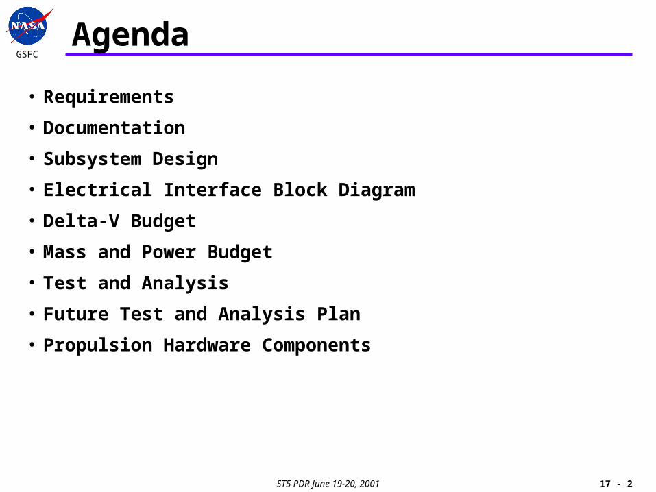
Agenda
• Requirements
• Documentation
• Subsystem Design
• Electrical Interface Block Diagram
• Delta-V Budget
• Mass and Power Budget
• Test and Analysis
• Future Test and Analysis Plan
• Propulsion Hardware Components

ST5 PDR June 19-20, 2001
GSFC
17 - 3
Key Level II Requirements
• The propulsion subsystem shall include a cold gas micro-thruster system. (MRD10302010)
– The ST5 propulsion subsystem is a GN2 cold gas system based on the Marotta cold gas micro-thruster.
• Estimates of supply pressure shall be provided by direct pressure telemetry and/or a combination of indirect temperature telemetry and thruster on-time tracking. (MRD10302030)
– The ST5 propulsion subsystem includes a miniature pressure transducer by GP:50 to allow direct pressure telemetry.
– Tank pressure can be calculated from tank temperature and thruster on-time data.
• The thruster shall provide telemetry indicating the previous actuation activity of the thruster valve. (MRD10101040)
– The thruster control electronics (TCE) includes an indicator to monitor current pulses going to the solenoids.

ST5 PDR June 19-20, 2001
GSFC
17 - 4
Key Level II Requirements
• The thruster shall operate in continuous mode, or pulsed mode. (MRD10302011)
– The cold gas micro-thruster is capable of operating from 0.05 sec. minimum pulse width to continuous firing.
• The propulsion subsystem shall provide a maximum delta-V of 7.6 m/s. (MRD10302020)
– The 15cm (6” OD) tank pressurized to 13.8 Mpa (2000 psia) at BOL gives the system delta-V capability of 7.6 m/s.
• The thruster control circuitry shall have sufficient protections to preclude inadvertent thruster firings due to either hardware or software malfuctions. (MRD10302040)
– The TCE incorporates multiple safety features to prevent accidental thruster actuation that can lead to loss of propellant.

ST5 PDR June 19-20, 2001
GSFC
17 - 5
Key Level II Requirements
• The propulsion system shall be designed such that the pre-welded propulsion system can be installed as one complete and tested assembly to the spacecraft. (MRD10302050)
– Small size and simplified layout of the ST5 propulsion subsystem allows “assembly line” integration approach.
– Each propulsion subsystem is integrated on a duplicate bottom deck plate, which serves as an assembly jig.
– Each completed assembly is leak checked and tested for mechanical and electrical functions.
– Each completed assembly is integrated on to the spacecraft structure.
– The subsystem undergoes environmental test at the spacecraft level.
ST5 PDR June 19-20, 2001
GSFC
17 - 6
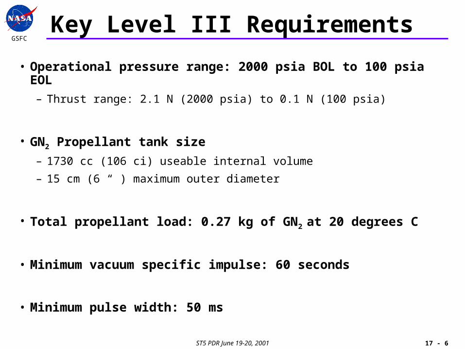
Key Level III Requirements
• Operational pressure range: 2000 psia BOL to 100 psia EOL
– Thrust range: 2.1 N (2000 psia) to 0.1 N (100 psia)
• GN2 Propellant tank size
– 1730 cc (106 ci) useable internal volume
– 15 cm (6 “ ) maximum outer diameter
• Total propellant load: 0.27 kg of GN2 at 20 degrees C
• Minimum vacuum specific impulse: 60 seconds
• Minimum pulse width: 50 ms

ST5 PDR June 19-20, 2001
GSFC
17 - 7
Key Level III Requirements
• ~1/3 Hz actuation frequency mode
– For attitude control (spin axis precession) at 20 rpm
– 50 ms to 2.95 s pulse widths in 50 ms increments
• 2 Hz actuation frequency mode
– For orbit adjustment at 20 rpm
– 50 ms to 450 ms pulse widths in 50 ms increments
• Capable of continuous firing
• Temperature range
– -20 to 40 degrees C operating
– -40 to 55 degrees C survival
• 1x10⁻⁴ scc/s He Maximum allowable system leakage rate

ST5 PDR June 19-20, 2001
GSFC
17 - 8
Documentation Status
• Propulsion Subsystem Specification ST5-495-019
– Preliminary
• Propulsion Subsystem Interface Control Document ST5-495-015
– Preliminary
• Cold Gas Micro Thruster SOW ST5-495-001
– Under Project Configuration Management
• Cold Gas Micro Thruster Specification ST5-495-002
– Under Project Configuration Management
• Other propulsion components SOWs and SPECs are in draft
– Propellant tank
– Pressure transducer
– Propellant filter
– Fill and drain valve
ST5 PDR June 19-20, 2001
GSFC
17 - 9
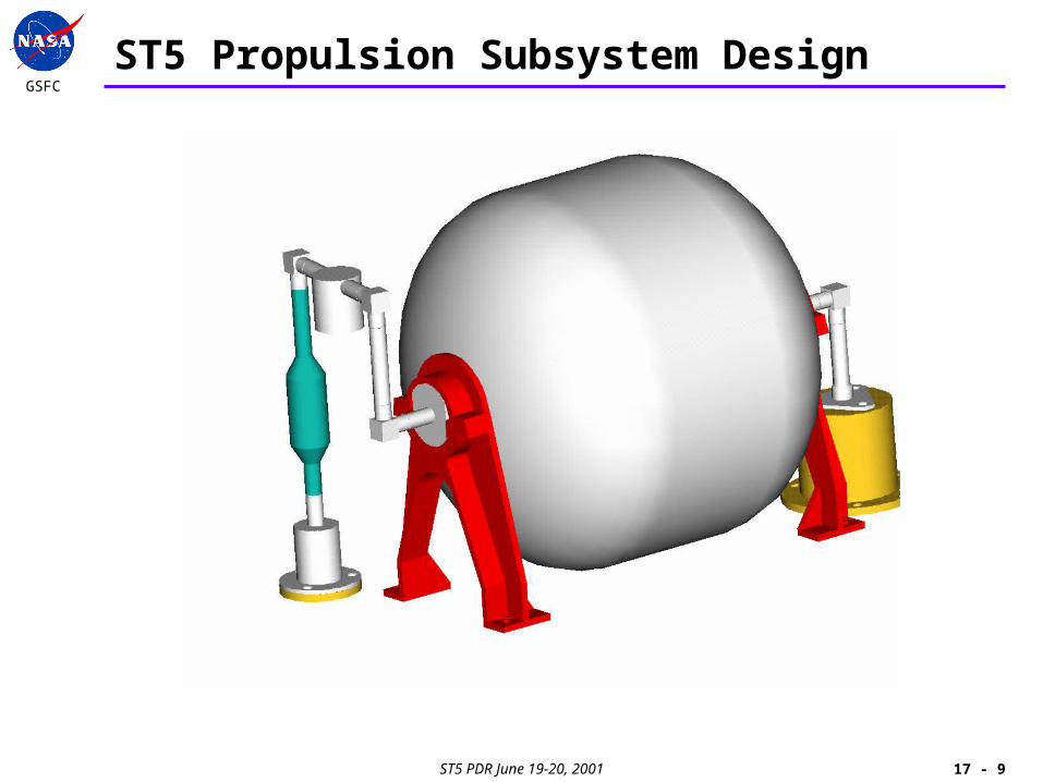
ST5 Propulsion Subsystem Design
ST5 PDR June 19-20, 2001
GSFC
17 - 10
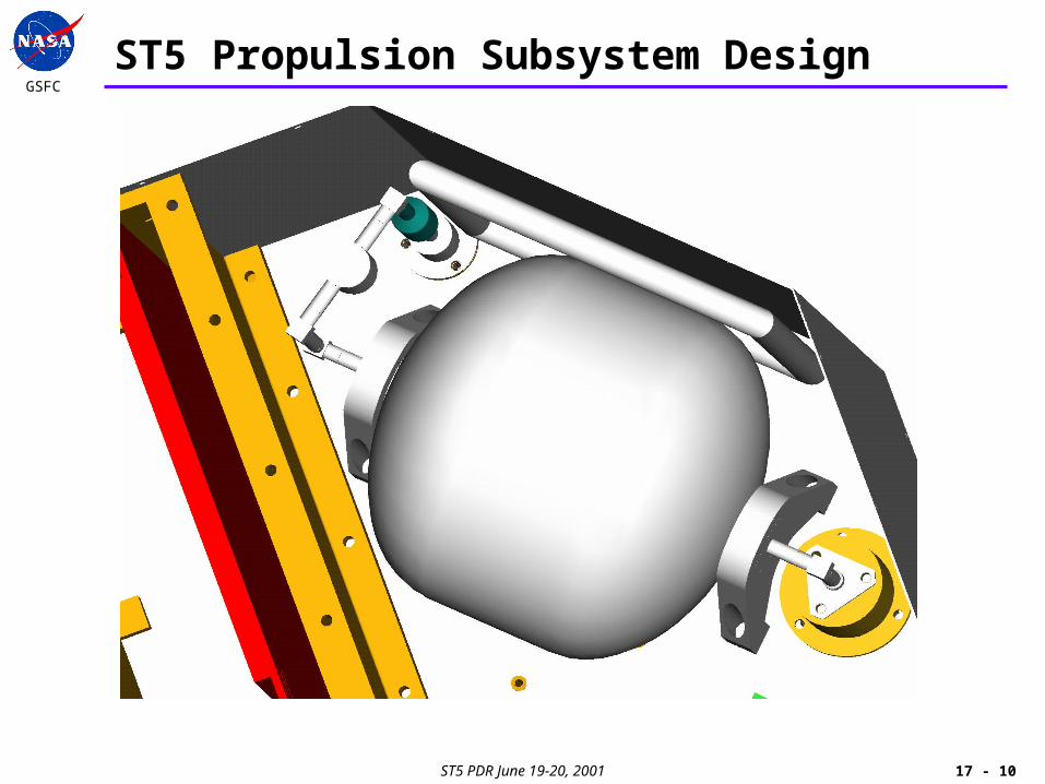
ST5 Propulsion Subsystem Design
ST5 PDR June 19-20, 2001
GSFC
17 - 11
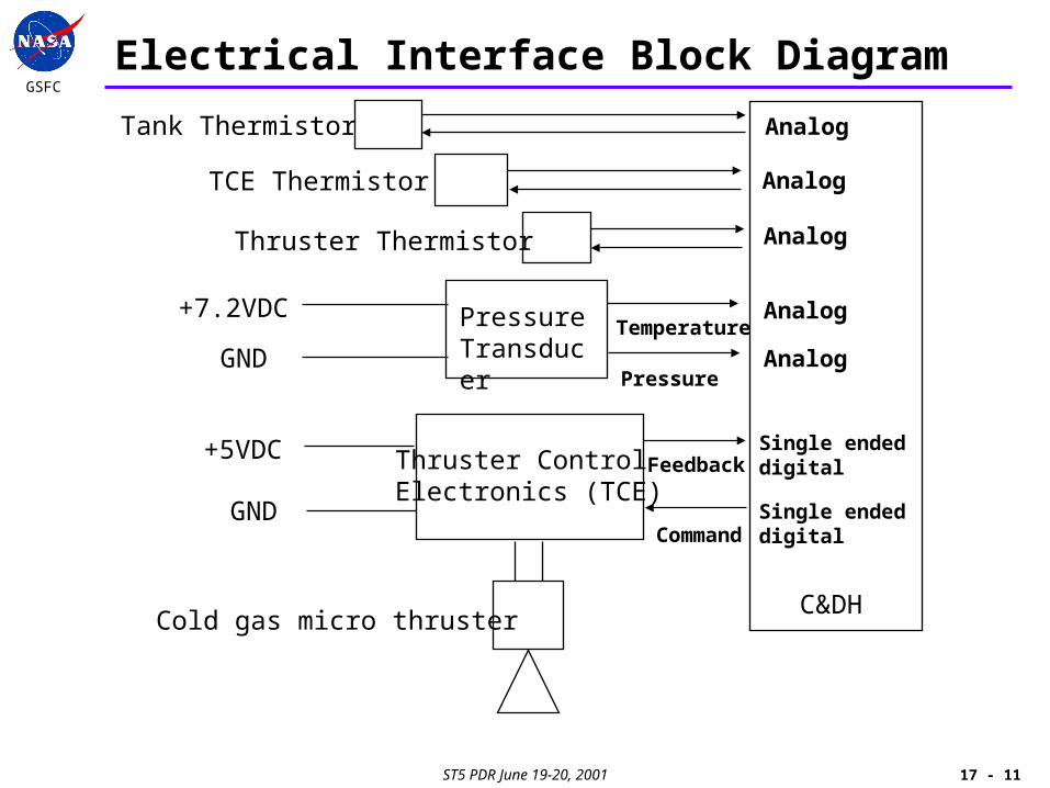
Electrical Interface Block Diagram
+5VDC
+7.2VDC
GND
GNDTemperature
Pressure
Feedback
Command
PressureTransducer
Thruster ControlElectronics (TCE)
Cold gas micro thruster
Tank Thermistor
TCE Thermistor
Thruster Thermistor
Analog
Analog
Analog
Analog
Analog
Single endeddigital
Single endeddigital
C&DH
ST5 PDR June 19-20, 2001
GSFC
17 - 12
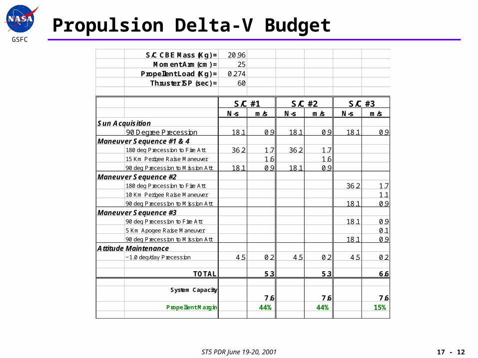
Propulsion Delta-V BudgetS/C CBE Mass (Kg) = 20.96
Moment Arm(cm) = 25Propellent Load (Kg) = 0.274
Thruster ISP (sec) = 60
N-s m/s N-s m/s N-s m/sSun Acquisition
90 Degree Precession 18.1 0.9 18.1 0.9 18.1 0.9Maneuver Sequence #1 & 4
180 deg Precession to Fire Att 36.2 1.7 36.2 1.715 Km Perigee Raise Maneuver 1.6 1.690 deg Precession to Mission Att 18.1 0.9 18.1 0.9
Maneuver Sequence #2180 deg Precession to Fire Att 36.2 1.710 Km Perigee Raise Maneuver 1.190 deg Precession to Mission Att 18.1 0.9
Maneuver Sequence #390 deg Precession to Fire Att 18.1 0.95 Km Apogee Raise Maneuver 0.190 deg Precession to Mission Att 18.1 0.9
Attitude Maintenance~1.0 deg/day Precession 4.5 0.2 4.5 0.2 4.5 0.2
TOTAL 5.3 5.3 6.6
System Capacity
7.6 7.6 7.6Propellent Margin 44% 44% 15%
S/C #1 S/C #2 S/C #3
ST5 PDR June 19-20, 2001
GSFC
17 - 13
Propulsion Mass Budget
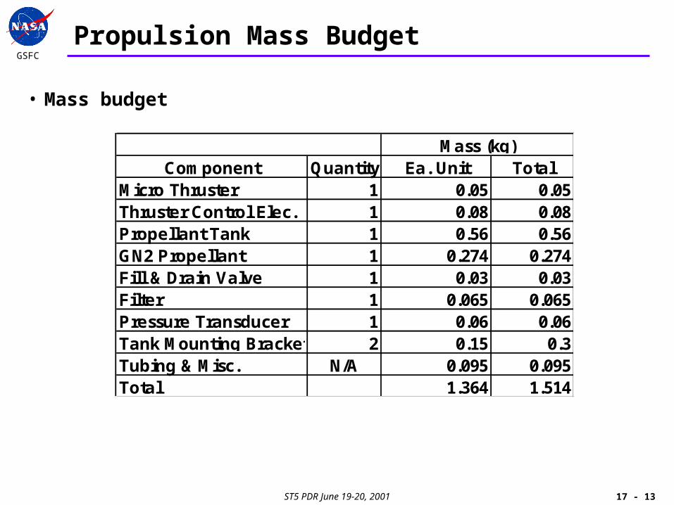
• Mass budget
Component Quantity Ea. Unit TotalMicro Thruster 1 0.05 0.05Thruster Control Elec. 1 0.08 0.08Propellant Tank 1 0.56 0.56GN2 Propellant 1 0.274 0.274Fill & Drain Valve 1 0.03 0.03Filter 1 0.065 0.065Pressure Transducer 1 0.06 0.06Tank Mounting Brackets 2 0.15 0.3Tubing & Misc. N/A 0.095 0.095Total 1.364 1.514
Mass (kg)

ST5 PDR June 19-20, 2001
GSFC
17 - 14
Propulsion Power Budget
• Power budget
Component Typical PeakMicro Thruster 0.6 1.5Pressure Transducer 0.2 0.2Total 0.8 1.7
Nominal Mode Power Dissipation (Watts)
ST5 PDR June 19-20, 2001
GSFC
17 - 15
Propulsion Test and Analysis
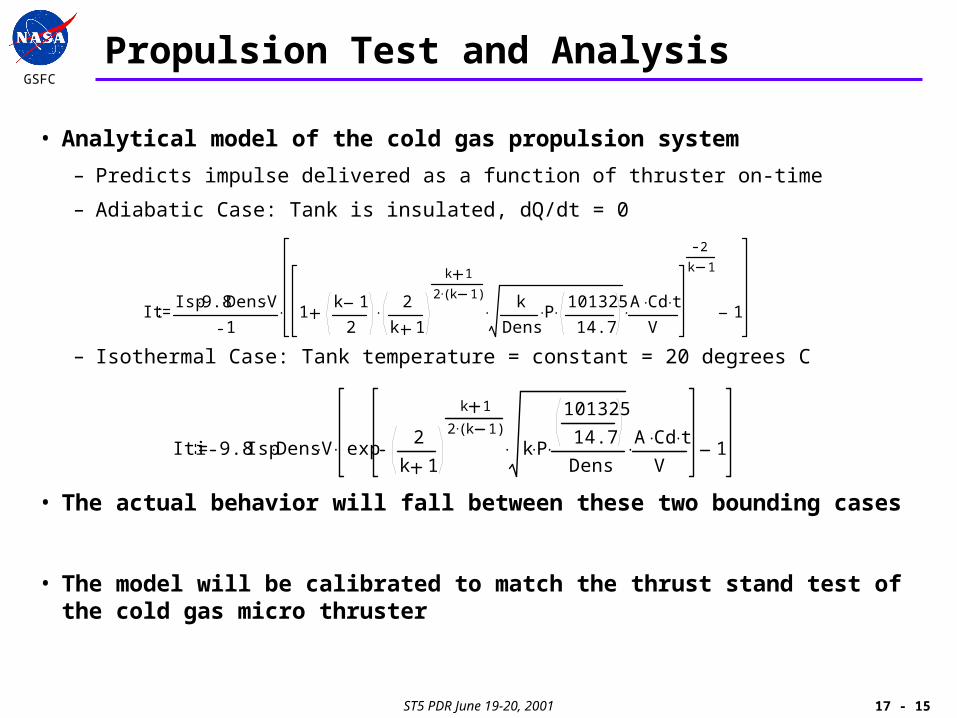
• Analytical model of the cold gas propulsion system
– Predicts impulse delivered as a function of thruster on-time
– Adiabatic Case: Tank is insulated, dQ/dt = 0
– Isothermal Case: Tank temperature = constant = 20 degrees C
• The actual behavior will fall between these two bounding cases
• The model will be calibrated to match the thrust stand test of the cold gas micro thruster
ItIsp 9.8 Dens V
11
k 1
2
2
k 1
k 1
2 k 1( ) k
DensP 101325
14.7 A Cd t
V
2
k 1
1
Iti 9.8 Isp Dens V exp2
k 1
k 1
2 k 1( )
k P
101325
14.7
Dens A Cd t
V 1
ST5 PDR June 19-20, 2001
GSFC
17 - 16
Propulsion Test and Analysis
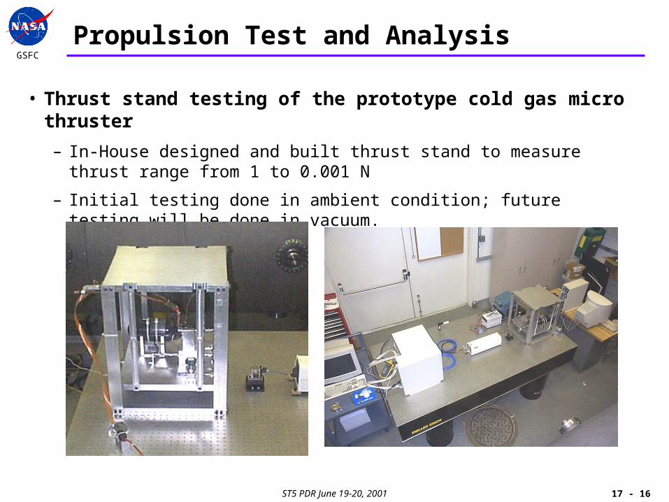
• Thrust stand testing of the prototype cold gas micro thruster
– In-House designed and built thrust stand to measure thrust range from 1 to 0.001 N
– Initial testing done in ambient condition; future testing will be done in vacuum.
ST5 PDR June 19-20, 2001
GSFC
17 - 17
Future Test and Analysis Plan
• In-House thrust stand testing of the cold gas micro thruster as a part of the qualification program
• Refined analytical model of the propulsion system based on thrust stand test results
• Create analytical model for predicting propellant usage based on thruster on time data and tank temperature
• Structural analyses (Swales)
• Thermal analyses (Code 545 or Swales)
ST5 PDR June 19-20, 2001
GSFC
17 - 18
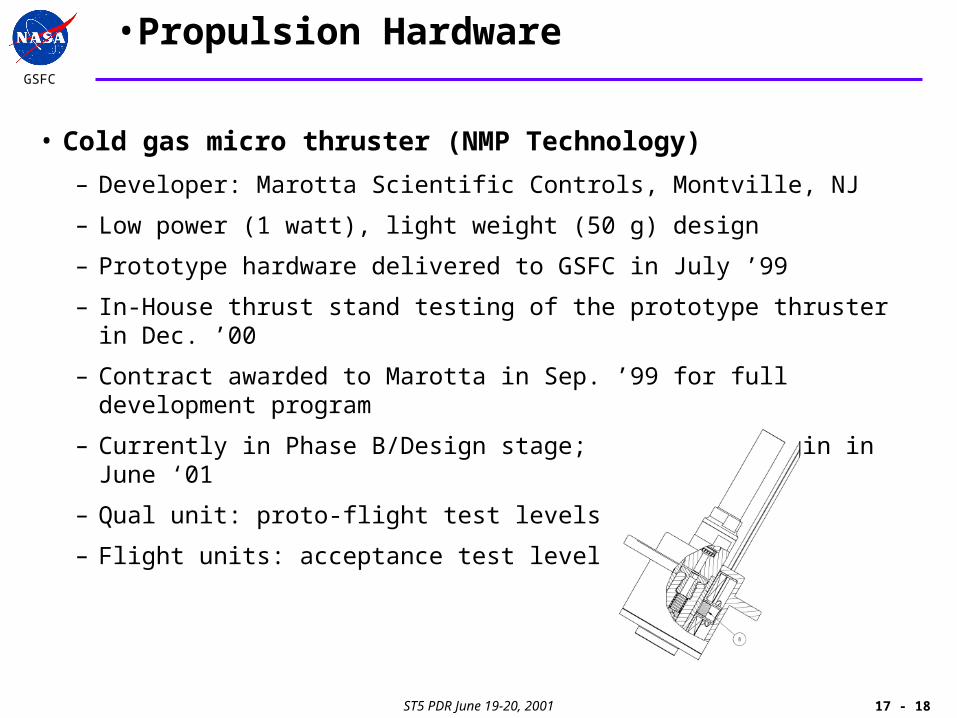
•Propulsion Hardware
• Cold gas micro thruster (NMP Technology)
– Developer: Marotta Scientific Controls, Montville, NJ
– Low power (1 watt), light weight (50 g) design
– Prototype hardware delivered to GSFC in July ’99
– In-House thrust stand testing of the prototype thruster in Dec. ’00
– Contract awarded to Marotta in Sep. ’99 for full development program
– Currently in Phase B/Design stage; Phase C to begin in June ‘01
– Qual unit: proto-flight test levels
– Flight units: acceptance test levels

ST5 PDR June 19-20, 2001
GSFC
17 - 19
Propulsion Hardware
• Thruster Control Electronics (NMP Technology)
– Developer: Marotta Scientific Controls, Montville, NJ
– Prototype TCE delivered to GSFC in July, ’99
– Contract awarded to Marotta in Sep. ’99 for full development program
– Currently in Phase B/Design stage; Phase C to begin in June ’01
– Incorporates multiple safety features for increased reliability
• Telemetry Feedback Signal
• Thruster ON Limit Timer
• Thruser ON Limit Timer Disable
• Disable Valve Open Command when Capacitor Charge is too low
• Automatic Valve Close on Power Loss
– Qual unit: proto-flight test levels (To be performed In-House)
– Flight units: acceptance test levels (To be performed In-House)
ST5 PDR June 19-20, 2001
GSFC
17 - 20
Propulsion Hardware
• Baseline Pressure Transducer
– Vendor: GP:50
– 7.2 VDC, Low power (200 mW), lightweight (60 g) design
– Analog electronics previously flown in STS
– ST5 version will undergo full qualification program based on ST5-495-007, “Component Test Requirements and Guidelines”
– Current status: SOW and Spec completed. Ready to start procurement.
• Miniature Fill and Drain Valve and Propellant Filter
– Vendor: Vacco
– Fully qualified, COTS
– Deliverables: Three flight units with acceptance data packages
– Current Status: SOW and Spec completed. Ready to start procurement.

ST5 PDR June 19-20, 2001
GSFC
17 - 21
Propulsion Hardware
• Propellant Tank
– Vendor: Carlton Technologies Inc.
– Lightweight composite vessel: carbon fiber with aluminum liner
– Proof factor of 1.5x MEOP; Burst factor of 2.0x MEOP
– Full qualification program based on MIL-STD-1522A and ST5-495-007 “Component test requirements and guidelines”
• One qual unit for cycle test (min. 50 cycles) and burst
• Three flight units (leak and proof)
• Environmental testing at the spacecraft level
– Current Status: SOW and Spec completed. Ready to start procurement.
ST5 PDR June 19-20, 2001
GSFC
17 - 22
Risk Mitigation – Delta-V Budget
• Risks to Available Performance– Increase in S/C Mass
• Current propulsion system delta-V capacity based on 20.96 kg spacecraft mass• Any increase in spacecraft mass will reduce the system delta-V capacity
– Thruster Isp is lower than 60 sec.• Current Predictions for Isp Analytically Based• Ambient Measurements of Performance Lower Than Expected• Currently Updating Model and Planning In-Vacuum Testing
• Mitigation– Alter Constellation Design
• Eliminate Apogee Raise Maneuver Sequence• No Impact to Mission Success or Resources
– Change Propellant• Use of Heavier Fuel, at Lower Isp Can Yield Significant Increase in Delta-V at Same
Volume and Pressure• Impact: Increase in Spacecraft Mass
– Increase Tank Volume• Increase in Available Propellant for Same Pressure• Impact: Increase in Both Spacecraft Volume and Mass


![[Presentation] Topic 1 Mr. Rhee [互換モード]](https://img.pdfslide.net/doc/110x75/6280f1faa0e87f246449127c/presentation-topic-1-mr-rhee-.jpg)