Embed Size (px)
Citation preview

Section 2
ARCHITECTURAL DESIGN REQUIREMENTS

Architectural Design Criteria : Section 2
May 2013 Section 2 of Architectural Design Criteria – Revision A2
Page-1/31
Architectural Design Requirements
CONTENTS
1 OBJECTIVES 4 1.1 General 4 1.2 Architectural aims 4 1.3 Clarity and simplicity 4 1.4 Buildability 4 1.5 Integration with commercial or other facilities 4 1.6 Existing Infrastructure 4 1.7 Future Expansion 4 1.8 Legislation 5
2 ACCESSIBILITY 6 2.1 Pedestrian Access 6 2.2 Congestion 6
2.2.1 General 6 2.2.2 Simulation 6 2.2.3 Level of Service (LOS) 7
2.3 Service Access 7 2.4 Emergency Access 7 2.5 Equipment Access 7
2.5.1 General 7 2.5.2 Underground Stations 7
2.6 Cyclist Access 7 2.7 Taxi / Drop-off Access 7 2.8 Access into future developments 8
3 PUBLIC SAFETY 9 3.1 General 9 3.2 Fire 9 3.3 Station Means of Escape 9 3.4 Emergency Access 9 3.5 Handrails and Railings 9 3.6 Slipping and trip hazards 9 3.7 Avoidance of obstructions 10 3.8 Avoidance of Hazards 10 3.9 Road Safety 10 3.10 Public Health 10 3.11 Weather Protection 10 3.12 Visual Contrast 10
4 VERTICAL CIRCULATION 12 4.1 General 12 4.2 Provision 12 4.3 Stairs and Ramps 12 4.4 Escalators 12 4.5 Lifts 12 4.6 Numbering and Naming Levels 13
5 COMPONENTS 14 5.1 General 14 5.2 Component accessibility 14 5.3 Wall mounted components 14 5.4 Floor mounted components 14 5.5 Ceiling mounted components 14
6 ARTWORK 15

May 2013 Section 2 of Architectural Design Criteria – Revision A2
Page-2/31
6.1 General 15 7 E&M INTERFACES 16
7.1 General 16 7.2 Service routing 16 7.3 Wet Services routing 16 7.4 Service routing in Rail Facilities 16 7.5 Services in staff areas (excluding plant rooms) 17 7.6 Lighting 17 7.7 Double Slab 17
8 FINISHES AND MATERIALS 18 8.1 General 18 8.2 Exposed Concrete 18 8.3 Waterproofing requirements 18 8.4 Glazing 18 8.5 Tiling 18 8.6 Doors and Hatches 18 8.7 Floor finishes 19
9 STREETSCAPE 21 9.1 General 21 9.2 Environment 21 9.3 Landscaping 21
10 INTERFACING DEVELOPMENTS 22 10.1 General 22 10.2 Future Developments 22 10.3 Safety 22 10.4 Regulatory 22 10.5 Design 22
11 SIGNAGE AND ADVERTISING 23 11.1 General 23 11.2 Operational signage 23 11.3 Facility Identification 23 11.4 Statutory signage 23 11.5 Advertising 23
12 ACOUSTIC DESIGN 24 12.1 General 24 12.2 Layout 24 12.3 Interior public spaces 24 12.4 Staff Offices 24 12.5 Noise Damping 24 12.6 Interfacing developments 24
13 WEATHER PROTECTION 25 13.1 Flood prevention 25 13.2 Drainage 25 13.3 Dust 25 13.4 Rain 25 13.5 Sun 25
14 SECURITY 26 14.1 General 26 14.2 Personal Security 26 14.3 Human Barriers 26 14.4 Layout 27
15 COSTS 28 15.1 General 28
16 EASE OF MAINTENANCE 29

May 2013 Section 2 of Architectural Design Criteria – Revision A2
Page-3/31
16.1 General 29 16.2 Design 29 16.3 Strategy 29 16.4 Floor, Ceiling and Wall Finishes 29 16.5 Maintenance Boundary 29
17 FARE COLLECTION 30 17.1 Layout 30 17.2 Service Counters 30 17.3 Ticket / Add Value Machines 30 17.4 Station AFC Gates 30 17.5 Station Service Gates 31

May 2013 Section 2 of Architectural Design Criteria – Revision A2
Page-4/31
1 OBJECTIVES
1.1 General
Land transport facilities are intended for the people of Singapore and shall be representative of their sophistication, dignity and achievements.
The Authority has determined a set of design objectives for these which designers are required to meet.
Other design objectives may be required to suit the needs of particular locations.
1.2 Architectural aims
The design shall be appropriate to the local context; simple and clear in plan, section and detail and employ materials and colours suited to the function of the facility.
Designers shall explore volume, proportion, colour, materials, lighting, and contrast to enhance the user’s appreciation of the facility.
The Designer shall consider the scale and character of the surrounding urban fabric in designing above ground structures.
The Designer shall consider where-ever possible to providing unique design features within an individual facility in order to promote ease of identification particularly at station platforms along a single line.
1.3 Clarity and simplicity
Efficient use shall be made of space. Designers shall ensure that facilities are planned to reinforce the recognition of pathway, destination and function. The designer shall maximise views between levels particularly at locations leading to vertical circulation elements. Backtracking and changes of direction shall be minimised where possible with the aim of ensuring a direct line of sight in pedestrian flow and the safety of the travelling public.
Structural solutions should optimise use and visual clarity of the space. Columns, where necessary, shall be co-ordinated with the vehicle module to minimise visual and physical interuptions.
Signage shall be incorporated as an aid in wayfinding.
1.4 Buildability
The designer is encouraged to explore innovative solutions to determine the most appropriate building systems and products to be used to meet the statutory buildability requirements.
Through the use of repetitive grids, connection details and prefabricated components, the designer shall aim to achieve faster construction and improvements in quality.
1.5 Integration with commercial or other facilities
The primary purpose of transport facilities shall not be compromised through the introduction of commercial or other facilities. Where provided, these shall not result in congestion, confusion or disorientation.
Where future development will be located above transport facilities, designers shall provide the optimum structural grid for the development without compromising public safety, movement, organisational clarity, simplicity, or visibility in the facility.
1.6 Existing Infrastructure
Proposed modifications shall seek to maintain the existing character of the affected transit facility with significant design elements being identified prior to concept design through the preparation of Heritage Reports.
A Heritage Report is to be submitted for approval by the Authority. It shall contain, but not be limited to, the following:
- Identification of significant elements of the affected facility, such as iconic architecture, double height volumes, and small but locally significant details such as colour schemes
- Discussion of how the identified heritage elements may be integrated into the proposed design.
- Drawings and images to convey the above.
1.7 Future Expansion
Transport facilities shall be planned to accommodate future increases in passenger numbers and integration with future developments.

May 2013 Section 2 of Architectural Design Criteria – Revision A2
Page-5/31
1.8 Legislation
Transport facilities shall be designed to comply with the laws and regulations of the Republic of Singapore.

May 2013 Section 2 of Architectural Design Criteria – Revision A2
Page-6/31
2 ACCESSIBILITY
2.1 Pedestrian Access
Designers shall ensure that transport facilities :
- Are in accordance with the Building Control Regulations
- Are accessible to people with disabilities in accordance with the current edition of the Code on Accessibility in the Built Environment.
- Are modally integrated.
- Have a clear sequence of spaces each indicative of their function.
- Are designed in accordance with the principles outlined in the Guidelines for Enhanced Building Security by MHA
Designers shall ensure that stations are accessible according to the Guide to the layout of the tactile Guidance System in MRT and LRT Stations.
Each transport facility building shall have at least one designated barrier free route leading into the building and linking to all possible passenger destinations within the building in compliance with the Code on Accessibility in the Built Environment.
All disabled access routes into the transport facilities shall, where possible, be via the main entrance.
Application of multiple barrier free routes shall be considered for transport facilities with multiple major passenger flow routes.
Doors astride the tactile route shall be automatic or permanently fixed open. Automatic doors shall be sliding in preference to swing doors.
All doors accessed by the public shall require a maximum force of 22N to open or close.
2.2 Congestion
2.2.1 General All congestion modeling and calculations shall be based on projected passenger figures provided by the Authority or site survey data weighted to suit future site loadings to the approval of the Authority
Designers shall assess predicted passenger movement, capacities and waiting times at circulation elements during peak operations.
Designers shall ensure clear widths leading to all transport facilities allow uncongested access.
Station designers shall demonstrate that platforms can be cleared prior to the arrival of the next train during normal peak operations.
The capacity and flow per escalator and fare gate shall be as advised by the Authority. The quantity of both escalators and fare gates shall be defined by the designer to meet the projected patronage figures. Future expansion or removal of escalators and fare gates shall be included in the design to cater for future projected changes in demand. Facilities for the delivery, installation or removal of such elements shall be allowed for and highlighted in the design.
2.2.2 Simulation Congestion and pedestrian flow within and leading to all transport facilities shall be assessed using pedestrian simulation software against the maximum projected pedestrian numbers. Reassessments shall be undertaken given any significant changes to a design or projected passenger numbers.
Simulations shall be carried out for both the peak evening and morning hours or any other critical period as advised by the Authority. Within the peak hours being simulated a peak within the peak shall be include by introducing a 1.3 weighting to the central 20 minutes of the simulated hour.
The influence of walls, balustrades or other obstructions shall be considered in the simulation by the inclusion of a 0.3 meter zone beyond the obstruction were there is no pedestrian movement.
The influence of shops alongside access routes shall be considered in the simulation by the inclusion of a 1 meter zone beyond the shop front were there is no pedestrian movement.
The influence of waiting and queuing areas such as for ticket machines or other vending machines shall be allowed for to the approval of the Authority.
The simulation shall include any interfacing station or bus interchanges (both existing and under construction) and make allowance for all trains and pedestrian movements within the completed interchange. Recommendations for retrofitting measures within the existing infrastructure shall be included in the report.
The scope of the study shall include allowance for redundancy in the provision of escalators. Multiple scenarios shall be simulated and reported in which any one escalator is unavailable to cater for overhaul (Can't be used as a staircase).

May 2013 Section 2 of Architectural Design Criteria – Revision A2
Page-7/31
2.2.3 Level of Service (LOS) The Level of Service (LOS) shall be included as one of the pedestrian simulation outputs.
LOS ranges shall be as defined by J.J.Fruin (Pedestrian Planning and Design) and attached below;
Level of Service (LOS)
Density (m2/Pedestrian)
Circulation Spaces Staircases Waiting Areas
A > 3.3 > 1.9 > 1.2 B 2.3 - 3.3 1.4 – 1.9 0.9 – 1.2 C 1.4 – 2.3 0.9 – 1.4 0.7 – 0.9 D 0.9 – 1.4 0.7 – 0.9 0.3 – 0.7 E 0.5 – 0.9 0.4 – 0.7 0.2 – 0.3 F < 0.5 < 0.4 < 0.2
Maximum LOS (per minute of the simulation):
- Corridors linking two transport facilities with no commercial facilities, transit facilities (eg ticket machines) or information signage on either side, includes no waiting areas, meeting areas or decision points and where there is only bidirectional flow (ie no cross flow) – shall not exceed LOS D. Time spent at LOS D may only be periodic across the peak period and shall be presented for the approval of the Authority.
- All other locations – shall not exceed LOS C.
2.3 Service Access
One access shall be provided for maintenance and/or refuse collection vehicles. A parking space shall be provided adjacent to an entrance containing a lift from concourse to street level and to the bin centre/point. Alternative access provisions may be proposed if seriously constrained by space
Unsecured Service Access shall never be positioned below transport facility structure.
2.4 Emergency Access
See ‘Public Safety’ Section.
2.5 Equipment Access
2.5.1 General Access shall be considered for any replacement of equipment and plant. This shall include allowance for clear door openings, access hatches, clear corridor passageways, demountable panels, hoisting facilities, additional equipment loads affecting structural members along the access route and anything else as identified in co-ordination with the equipment suppliers and Contractor.
Knock-out panels for equipment access are not acceptable.
Roller shutters are not acceptable for access in any trackside environment due to pressure variations causing the shutter to rattle.
Clear access paths from the equipment entry point to their installation point of an appropriate clear width, height and turning radiuses shall be provided. Clear corridor and door widths and heights shall be provided to accommodate all future foreseen equipment removal and installation.
2.5.2 Underground Stations In general equipment access to the station concourse level is gained through a hatch from the trackway. This may be directly into the TVF Rooms if they are located at each end of the station above the trackway. Otherwise the access hatch may open into an alternative space and movement of the equipment to the TVF and other ancillary rooms shall be determined accordingly.
Access may also be provided by use of a shaft from the ground level.
Any access hatches from the trackway shall open directly above the station trackway and hoisting beams shall be provided at the soffit of the concourse level, over the access hatch openings, to facilitate the transfer of equipment between the station trackway and concourse. The access hatch opening shall align with the track and shall not infringe into the buffer areas. The location of access hatches shall take into consideration the required circulation space around the opening for working and escape.
2.6 Cyclist Access
A bicycle parking area shall be provided as required.
There shall be no bicycle parking lots within 5m from any glazing entrance structure.
2.7 Taxi / Drop-off Access
Any taxi-stand and passenger drop-off points serving a particular transport facility shall be positioned as close as is feasible, given site constraints, to the designated disabled access entrance.

May 2013 Section 2 of Architectural Design Criteria – Revision A2
Page-8/31
2.8 Access into future developments
Provision of knock-out panel for future development directly linking to the transport facility shall be considered. This future access shall be provided with sufficient space to allow for erection of hoarding and working in future.
May 2013 Section 2 of Architectural Design Criteria – Revision A2
Page-9/31
3 PUBLIC SAFETY
3.1 General
Transport facilities shall be designed to assure all users that they are in a safe environment.
3.2 Fire
Monitoring devices, alarms, fire detection and suppression equipment shall be integrated into the facility as required by the current E&M Criteria.
Where transport facilities are integrated into other developments, they shall be provided with unique escape provisions.
Routes of escape shall be along main circulation routes rather than designated escape staircases where-ever possible.
All fire safety provisions in the Rapid Transit System shall be designed according to the requirements of the ‘Standard for Fire Safety in Rapid Transit Systems’.
All fire safety provisions in other facilities, such as bus interchanges and depots, shall be designed according to the requirements of the Code of Practice for Fire Precautions in Buildings.
3.3 Station Means of Escape
Station means of escape shall be provided as required in the Standard for Fire Safety in Rapid Transit Systems. In addition, it must be demonstrated that the means of escape provided are also able to meet future demand based on the optimum Station Occupant Load calculated as follows:
Optimum Station Occupant Load = 1 Crush Train Load for the peak direction + 1 Peak Train Load for each non-peak direction + Entraining Load of platform(s) based on occupant density of 0.9m
2/pax
3.4 Emergency Access
Emergency access shall be provided in accordance with the requirements of the current edition of the Standard for Fire Safety in Rapid Transit Systems and the Code of Practice for Fire Precautions in Buildings.
3.5 Handrails and Railings
Barriers shall be provided at all abrupt changes of level greater than 450mm accessible to the public including at public area staircases and landings. These barriers shall be a minimum of 1.1m overall height measured vertically from the adjacent finished floor level or pitch line of a flight of stairs to the top of the highest continuous horizontal member.
The design of railings terminating at an escalator shall be integrated and consistent with any escalator handrail. A proper interfacing detail is required to close the gap between both.
The fixing bracket to any handrail shall be on the underside and shall not impede the hand hold along the whole length of the railing.
Refer to the Civil Design Criteria Chapter 3 for requirements relating to live loads at handrailing and balustrades.
Handrails at ramps shall be continuous throughout the entire length (including beside any intermediate landings).
The clear width of a staircase shall be measured from the outside edge of the wall or balustrade and shall be clear of all projections except handrails which shall protrude no more than 105mm from the wall of balustrade.
Handrails and grab bars on the accessible route shall contrast with the colour of its background to aid visibility.
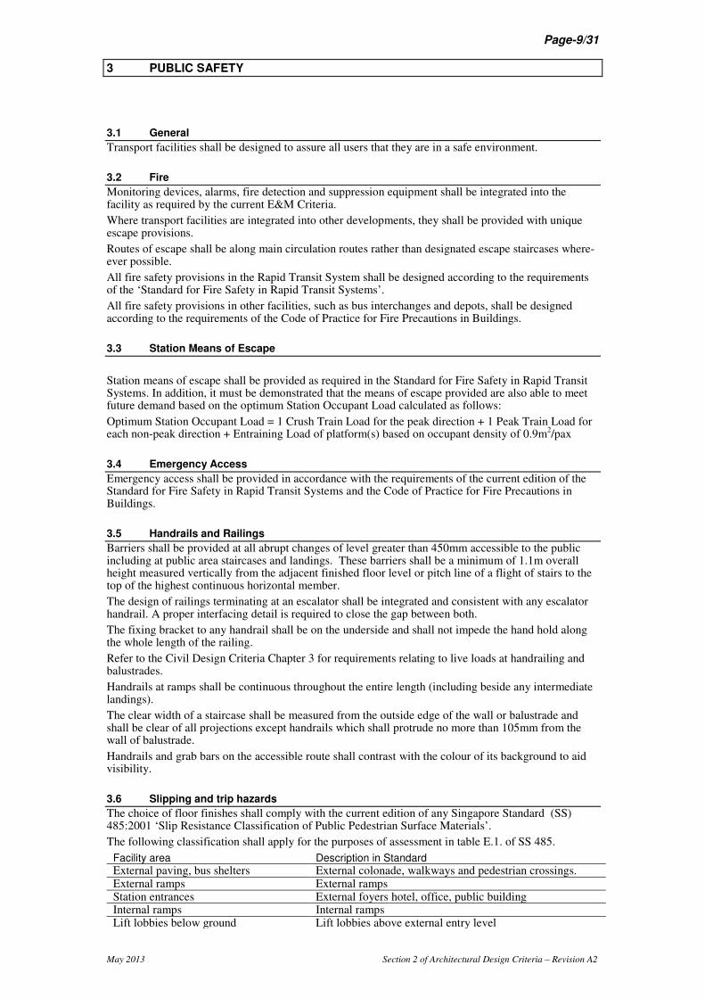
3.6 Slipping and trip hazards
The choice of floor finishes shall comply with the current edition of any Singapore Standard (SS) 485:2001 ‘Slip Resistance Classification of Public Pedestrian Surface Materials’.
The following classification shall apply for the purposes of assessment in table E.1. of SS 485.
Facility area Description in Standard
External paving, bus shelters External colonade, walkways and pedestrian crossings. External ramps External ramps Station entrances External foyers hotel, office, public building Internal ramps Internal ramps Lift lobbies below ground Lift lobbies above external entry level

May 2013 Section 2 of Architectural Design Criteria – Revision A2
Page-10/31
Toilets Toilet facilities in offices, hotels, shopping centres Underpasses, subways and passages Undercover concourse areas of sports stadium Station and bus interchange concourse Undercover concourse areas of sports stadium Station platform Undercover concourse areas of sports stadium Stair treads External stair nosings
Trip hazards shall be avoided.
Where two floor materials meet, the floor shall be level across the junction to avoid any trip hazard.
Single risers at changes of level shall be avoided. There shall be a minimum of three.
All steps shall be fitted with non-slip nosing strips between 50mm and 65mm in width. Rubber nosing strips are not acceptable for both internal and external staircases.
All external stair treads shall be well drained to prevent water from ponding on the tread.
3.7 Avoidance of obstructions
Obstructions within public spaces shall be avoided in compliance with current edition of the Code on Accessibility in the Built Environment.
Wall mounted furniture and components, including handrail extensions, shall be located to minimise intrusion into the pedestrian flow areas.
3.8 Avoidance of Hazards
Lighting shall be provided in accordance with the requirements of the Room Data Sheets and Commuter Facility Check Lists. Areas of shadow shall be avoided and lighting shall be evenly spread particularly along ramps.
Clear line of sight shall be maintained as far as possible with an avoidance of recesses, hidden corners, and visual obstructions.
Sharp edges or corners shall be avoided.
Rough textured and reflective wall finishes shall be avoided where people come into contact with it.
Upstands shall be provided at the sides of all drops to prevent items rolling down and landing on people below.
Doors swinging out into the public area shall be avoided particularly across defined pedestrian routes.
3.9 Road Safety
There shall be no shared routes between pedestrians and moving vehicles at all surface structures.
Kerb ramps shall not project into the road.
Pedestrian routes shall not pass behind reversing vehicles.
The lateral clearance between the outer edge of the road kerb and any element shall be minimum 0.6m.
3.10 Public Health
Adequate drainage and falls shall be provided to eliminate any possibility of ponding water adjacent to surface structures.
Anti-mosquito measures shall be taken in accordance with the requirements of ENV.
3.11 Weather Protection
Refer to Weather Protection Section
3.12 Visual Contrast
In general visual contrast for visibility of elements shall be attained by having a minimum of 30% luminance or brightness contrast. The use of colour contrast may also be used subject to the approval of the Authority. Ideally any contrasting colours used to distinguish elements for the visual impaired shall also have 30% brightness contrast.
Seats, sanitary fittings in the disabled toilet, grab bars, door handles, railings, end panels to phone booths and any elements used by the public shall contrast in colour or tone from their surroundings.
If an obstruction is inevitable it shall contrast with its surroundings.
The wall and floor in the public area shall use contrasting finishes.
There shall be a permanent tonal contrast between treads and nosing for all steps.
Colour contrast shall be provided at the intermediate landings along a ramp
300mm wide tactile warning strips shall be provided across the entire width at the top and bottom of any ramp where the change in level is greater than 200m and gradient steeper than 1:25. For 200mm rise or less refer to the Code on Accessibility in the Built Environment.

May 2013 Section 2 of Architectural Design Criteria – Revision A2
Page-11/31
Tactile routes shall terminate at the end of the ramp at the tactile warning strip 300mm to 600mm off to the side of the handrail, it shall restart from the opposite warning strip at the other end of the complete ramp 300mm to 600mm off to the side of the same handrail.

May 2013 Section 2 of Architectural Design Criteria – Revision A2
Page-12/31
4 VERTICAL CIRCULATION
4.1 General
Vertical circulation constitutes a major feature in the design of an underground or elevated transport systems.
4.2 Provision
Designers shall demonstrate that the provision of vertical circulation elements complies with the requirements of the current edition of the Standard for Fire Safety in Rapid Transit Systems and the Code of Practice for Fire Precautions in Buildings.
Designers shall also demonstrate that the provision of vertical circulation elements satisfies the time required to clear the public areas to avoid congestion.
The area occupied by vertical circulation elements shall not impinge on the circulation and waiting areas in peak conditions.
Vertical circulation elements shall be located to provide balanced distribution and facilitate convenient exiting of passengers within the transport facility.
Vertical circulation elements comprising stairs, escalators and lifts shall be provided to suit the demand needs of the facility.
Where transport facilities are integrated into other developments, vertical circulation requirements of the facilities shall be calculated separately from those provided in the integrated development.
All changes in level on Barrier free routes shall be addressed via use of passenger lifts or ramps.
4.3 Stairs and Ramps
All stairs and ramps shall as a minimum be in compliance with the Building Control Regulations.
All public area staircases shall comply with the staircase requirements listed in the Code on Accessibility in the Built Environment with the following exceptions: - Where the staircase is an alternative to a lift as a means of access between two levels; there shall be no provision of a detectable warning surface at the top and bottom of the staircase and the tread and riser shall provide a staircase gradient that matches any adjoining escalator or 30 degrees (which ever is the least steep) and not be restricted to maximum 150m riser and minimum 300mm treads. - Where the staircase is an alternative to a ramp as a means of access between two levels; there shall be no provision of a detectable warning surface at the top and bottom of the staircase.
Landings for ramps and staircases shall be free from obstructions.
4.4 Escalators
Escalators shall be the primary means of moving passengers vertically within a station and bus interchanges integrated with developments.
Stairs shall be provided as an alternative to escalators.
Escalators should be grouped with stairs so that reverse peak flows can be accommodated from the same loading point. Staircase projection beyond the escalator length are to be avoided.
At transfer between transport facilities or nodes, escalators shall be provided between different platform and concourse levels in accordance with the projected passenger transfer figures.
For provision of escalators at commuter facilities refer to the commuter facilities checklists.
Specific maintenance access facilities shall be integrated within the ceiling/ wall finishes and highlighted in the maintenance strategy report wherever there are services or finishes more than 3 meters above any bank of 2 or more escalators, or where an escalator has no adjoining staircase.
There should be no protrusion within 300mm of the outer edge of the escalator handrail apart from any balustrade.
4.5 Lifts
Lifts shall be provided to ensure barrier free access to and between differing levels within a transport facility.
Designers shall consider the visual impact of a lift shaft within the transport facility.
Barrier free accessible lifts shall open to a lift lobby space to allow for circulation of wheel chair bound commuters.
May 2013 Section 2 of Architectural Design Criteria – Revision A2
Page-13/31
4.6 Numbering and Naming Levels
Level numbering and naming shall be determined and agreed with the Authority at the initial stage of design and shall consider both labelling during construction and the labelling for operation, including signage.
Allocation of level numbers to basements and floors follow the standard practice for Singapore. Grade or Ground floor is Numbered ‘01’, one floor above ground is Numbered ‘02’, Basement 1 is ‘B1’, Basement 2 is ‘B2’ etc.
A level is distinguished by having spaces which are independent to those above or below. If a space is attached to spaces above or below, the space is considered part of the adjoining spaces level. Cable chambers, ceiling access voids and underplatform spaces are considered part of the adjoining level.
Levels are not necessarily only those accessible by the public but may be for the housing of plant or other services. This would be represented by a two or more jump in the public areas level numbering.
If there is a planned or existing adjoining development which has established levels. The same numbering shall be carried across into the station at the equivalent levels. This will avoid complications in signage at later stages.
The Level Names shall compose of three components;
- Firstly the term ‘Level’
- Secondly the level number: ‘01’, ‘02’, ‘B1’, ‘B2’ etc.
- Thirdly an optional function identifier. There are two standard function identifier names in stations; ‘Platform’ and ‘Concourse’.
A typical example for an underground station is; ‘Level 01’, ‘Level B1 Concourse’, ‘Level B2 Platform
May 2013 Section 2 of Architectural Design Criteria – Revision A2
Page-14/31
5 COMPONENTS
5.1 General
All functional elements mounted to the wall, ceiling or floor are considered as components.
The layout of all components shall be such that they present a controlled and co-ordinated appearance on completion of the works.
The housing and support structures of any component shall reflect the functionality of the component whilst being integrated with the surrounding architecture.
The designer shall ensure that the component provision is not over specified.
The location and mounting of components must be co-ordinated with layout and choice of finishes.
5.2 Component accessibility
Refer to Accessibility and Ease of Maintenance for general access and maintenance of components.
The position and height of all components shall comply with the Authorities requirements and any relevant codes.
Only components that are used by the public are required to comply with the current edition of the Code on Accessibility in the Built Environment.
A clear level floor space of 900mm x 1200mm shall be provided in front of any components designated for use by members of the public with disabilities.
5.3 Wall mounted components
Wall mounted components include, but are not limited to, control panels, sockets, switches, phones, push buttons, extinguishers, break-glasses, signage, advertising, services outlets, service counters, speakers, light fittings, access hatches, and hose reels.
All wall-mounted components within the public area may be mounted on designated services panels. These shall be flush where possible and co-ordinated with adjacent wall finishes.
Elevations shall be used to demonstrate the relative location of all wall components along with any wall cladding joint lines, doors and relevant surrounding features such as landscaping and railings.
5.4 Floor mounted components
Floor mounted components include, but are not limited to; seating, signage, advertising, stand alone extinguishers, barriers, gates, ticket machines, ATMs, post boxes, other service machines, phones and bins.
Where possible front accessed floor mounted services that back onto a wall should be recessed into a niche within the wall. This niche shall allow for tolerances in the component’s dimensions as agreed with the Authority. Wall cladding used around any recessed components shall be designed for easy replacement given future changes to the component dimensions.
Floor mounted components shall be grouped at a common location and integrated where feasible.
Seating shall only be provided at designated waiting areas such as platforms, bus stops, taxi stands and bus interchange concourses unless particularly identified by the Authority.
5.5 Ceiling mounted components
Ceiling mounted components include, but are not limited to, speakers, sprinklers, detectors, lighting, signage, visual information displays, LCX, antennas, smoke curtains, roller shutters, ventilation grilles, and diffusers.
All ceiling components shall be fully co-ordinated with the ceiling layout and located to minimise penetrations through the ceiling fabric.
Reflected ceiling plans shall be used to demonstrate the relative position of components along with the ceiling grid, access panels and ceiling support structure.
Ceiling mounted signage or visual displays shall be located such that passenger’s view are not blocked or obscured by obstacles or have glare from sunlight or lighting and are easily reached for maintenance. Any displays above fare gates should be 1 to 2 meters away from the edge of the gates on the paid side.

May 2013 Section 2 of Architectural Design Criteria – Revision A2
Page-15/31
6 ARTWORK
6.1 General
The Authority may, at its discretion engage artists to provide specialist pieces of artwork for incorporation into the fabric of the transport facility.
The Designer will be expected to collaborate with any artist so employed and to modify his design, if required, to suit the incorporation of the artwork.
The position and integration of artwork relative to components and finishes shall be considered. Refer to Components and Materials and Finishes sections.

May 2013 Section 2 of Architectural Design Criteria – Revision A2
Page-16/31
7 E&M INTERFACES
7.1 General
E&M interfaces includes considerations for positioning, mounting, service routing, and maintaining of all E&M items within the facilities.
Refer to Components, Ease of Maintenance, and Fare Collection Sections
7.2 Service routing
The designer shall produce a service routing strategy.
The distribution of services within the transport facility shall follow designated service routing zones. Allowances shall be made for easy access to services within these zones.
Service zones may run above suspended ceilings or behind wall cladding but shall avoid any double height space. Particular attention shall be paid to the co-ordination of ceiling and wall support structures with the layout of services at these locations.
Routing of services within the public area ceiling void should be limited to those services required to serve elements housed in the ceiling or ceiling void.
Services or fittings directly above escalators shall be avoided. If possible any services and fitting should be located adjacent to escalators and proven to be serviceable without access or support directly from the escalator.
No M&E services are allowed to route through the protected shaft or fire essential rooms (refer to room datasheets) unless they are serving these areas or rooms.
Kerbs, 100mm from Finished Floor Level, shall be provided for E&M service penetration floor opening as co-ordinated with E&M service providers unless otherwise qualified by the E&M service providers. Clashes with equipment to be considered.
The depth of all electrical and service closets, if provided, shall not exceed 750mm depth. Otherwise, the space will be treated as a habitable room. Buildability, accessibility and maintainability of the services and components located inside the service closets shall be considered. Service closets shall not drop directly above the trackway. Closets, if required for fire dry riser pipes and pump and drainage systems, shall be located near to the pipes entry point in station and areas to be served in order to keep routing shortened.
7.3 Wet Services routing
No electrical, communications or signalling rooms shall be located adjacent to the water tanks or diaphragm walls, if unavoidable double walls shall be provided adjacent to the water tanks and dry walls adjacent to the diaphragm walls. This is to prevent potential water seepage and damage to the equipment.
No electrical, communications or signalling rooms shall be located on the base slab of the station box.
Water pipes not serving electrical and/or electronic rooms shall not pass through these rooms.
When planning room layouts, particular care is needed to avoid locating wet rooms that will require sanitary and drainage pipework, e.g. toilets, above electrical plantrooms. If this is not possible, the wet room shall be positioned to overlap above adjacent non-electrical room areas so that the floor traps and associated waste pipes penetrate the floor slab outside the electrical rooms.
No wet services (including those liable to condensation, e.g condensate drains, etc) are to be routed above or immediately in front of any operationally critical devices (Eg PSDs, Escalators, AFC Devices).
Floor traps, pipes, drains and pits shall be designed and positioned to suit the drainage of all sanitary waste, seepage, waste cleaning water, hose reel and condensate water.
7.4 Service routing in Rail Facilities
Service routing in rail facilities shall be in compliance with the Standard For Fire Safety In Rapid Transit Systems.
No services shall be allowed to cross over or be routed above the station trackway. Such services that need to cross the station trackway shall be routed either below the track or via other floor levels.
When planning room layouts at the floor level direct above platform level (typically concourse level) particular care is need to avoid locating rooms that will require sanitary and drainage pipework, e.g public or staff toilets to be installed at high level directly above the track. Every effort should be made to ensure that any room located directly above the track can be maintained or drainage pipework rodding etc can be undertaken without access to the track.
All cables crossing the tracks in tunnels shall either run underneath the rails, trackbed or fully recessed in second stage concrete slab or enclosed by cable troughs. No dry or wet riser pipework shall be

May 2013 Section 2 of Architectural Design Criteria – Revision A2
Page-17/31
embedded in concrete. Where such pipework is required to cross-over trackwork, the pipework shall have the shortest possible route and designed such that no flanges or joint shall exist above the track. However, in the event that crossing above the track is unavoidable, a double slab is required to segregate between the services and the track (See below).
Designated risers are to be provided for all services routing up to entrance level or ground level structures. Any direct penetration of E&M services through the station roof shall be avoided.
7.5 Services in staff areas (excluding plant rooms)
Wall mounted services within offices and areas with false ceiling (non-public) shall be enclosed or painted to match the wall finish. Wall mounted services within areas with tiled walls shall be concealed.
The designer shall ensure that the locations of the concealed services and equipment are coordinated with the furniture layout
7.6 Lighting
The Designer shall define the architectural lighting concept which shall be integrated with and enhance the overall architectural design intent. This shall extend to all public areas accessible and visible to the public within the transport facility.
The architectural lighting concept shall contribute to the design objectives of clarity in the passenger route and support the identification of key transport facility functions such as Service Counters, Ticket Machines, gatelines, vertical circulation elements, platforms, and entrance/exit routes. The ‘lit’ environment shall ensure an atmosphere of safety.
Glare and dazzle shall be avoided by determining the relative position and angle of lighting sources to the public and the reflectivity of finishes.
Lighting levels are defined in the MRT Station Room Datasheets or CF Architectural Checklists.
Each light shall contribute to attaining the required light level. Switching any of the individual lights off means that the light level is no longer achieved.
The designer shall consider the ease of maintenance in his lighting design strategy. Where double volume ceilings are located over the staircases and escalators, ceiling mounted lighting design shall be avoided unless the maintainability of the lighting system is demonstrated in the maintenance strategy.
7.7 Double Slab
Reinforced concrete double slab areas within the stations (including trackways) may be provided to facilitate the routing of E&M services over protected routes and trackways, and to relieve congested areas over protected rooms and other plant rooms. All double slab areas, wherever required, shall be reinforced concrete, unless specified otherwise by the Authority.
Wherever double slabs are used, the buildability, accessibility and maintainability of the services and components located inside the double slabs shall be considered. Compartmentation, access and design of any double slab shall comply with all fire regulations.
For stations, the function of the double slab includes use as an air plenum or protection to segregate the services routed within the protected areas, such as Exit Passageways, Firemen / Exit Staircases and / or Fire Essential Rooms etc. Double slabs shall be planned well in advanced commencing at preliminary design stage.
For station trackways, double slab may be introduced at the soffit above tracks for segregation purpose and/ or to facilitate the crossing of services (examples: pipes, ducting, cable trays and trunkings etc). Access to the double slab areas from either side of the double slab shall be provided.
May 2013 Section 2 of Architectural Design Criteria – Revision A2
Page-18/31
8 FINISHES AND MATERIALS
8.1 General
All materials used shall comply with the Material and Workmanship specification.
Finishes within the transport facility shall be robust, durable and suitable for their purpose.
All materials chosen for use in finishes shall be vandal resistant, and easily cleaned and maintained. In addition the materials shall have low maintenance requirements over their life span.
All materials used shall comply with the Standard For Fire Safety in Rapid Transit Systems and the Code of Practice for Fire Precautions in Buildings.
Designers are encouraged to work with a limited palette of materials within public areas and to strive for simple and functional detailing.
Materials used above ground shall all be corrosion and stain resistant with particular attention to resistance to fungal growth due to the humid atmosphere and water absorption from rain.
Finishes shall not require cyclical painting or re-coating unless a set period after which re-coating is required is agreed with the Authority. Access for replacement and ongoing maintenance shall be achievable by commonly available means.
Finishes shall not require customised cleaning equipment.
Particular finishes requirements are identified in following section of the ADC.
8.2 Exposed Concrete
Where no specific finish has been identified, any exposed concrete, including inside shafts, ducts and closets, shall, as a minimum, be finished with an anti-dust coating.
8.3 Waterproofing requirements
Particular attention is required to ensure that the floor, wall and ceiling finishes in areas in direct contact with ground, are dry.
In addition seepage walls with drainage facilities are to be provided along any perimeter walls in direct contact with the ground. In rooms containing electronic and electrical equipment except electrical cable chamber in underplaform level, occupied staff rooms, and all public areas, the dry lining to such walls shall be constructed using non-combustible materials, which shall be unaffected by moisture, provision being made for the ventilation of the cavity. Access panels shall be provided on these walls to allow regular and easy access to the drainage outlet points.
All wet rooms shall be provided with water-proofing membrane.
8.4 Glazing
Refer to Glazing Design Criteria.
8.5 Tiling
There shall be no tiling above 3m height.
Exposed walls above tile finishing are to be finished with skim coat and paint.
8.6 Doors and Hatches
8.6.1 Identification Wall doors and hatches shall be identified separately under the following categories:
- Security and Fire Doors, Hatches and Gates
- Cladding Hatches and Doors
- Access Hatches
- CD Doors.
Door and hatch requirements shall be specified during the design process using Building Information Modeling (BIM) software and displayed for review using 'Door Data Plans'.
The information shall be transferred to a ‘Door Schedule’ for procurement of the doors and hardware. All door schedules shall be divided by level with the schedule for security and fire doors, hatches and gates further divided into Rooms, Closets and Staircases. The designer shall specify on the relevant drawings that detailed shop drawings and schedules for both doors and ironmongery shall be provided by the suppliers to meet the technical requirements specified for the door.
The format of both the Door Schedules and Door Data Plans shall be as advised by the Authority.
May 2013 Section 2 of Architectural Design Criteria – Revision A2
Page-19/31
All doors connected with the fire escape routes shall be identified on the fire escape route plan for coordination with SWC which require the EM locks of the AMS system to unlock and release during fire mode.
8.6.2 Door Swing Door openings and direction of door swing shall be properly designed so as to avoid clashes when two or more sets of doors need to be opened / accessed at the same time.
Any doors, or active leaf of a double door, when open to 90 degrees that causes obstruction to an escape route shall close with the direction of escape.
All cable chamber access hatches shall be openable by one person. Facilities to hold open the hatch to be provided.
Active leaf of any double door to be identified on plan. Active leaf to be scheduled based on the side the hinges of the active leaf are on when facing the door from the pull side of the door.. Diagram to define the active leaf to be included on all door schedule submissions and drawings.
8.6.3 Security and Fire Doors, Hatches and Gates All doors shall be self-closing if they are for entry into a room.
Application of door hardware shall comply with the SFSRTS or Fire Code as applicable.
All doors used by the public shall comply with the Code on Accessibility in the Built Environment.
Kick plates shall only be applied to push side of wooden doors to toilets, cleaning and cooking facilities or as identified by the Authority.
Flush bolts for doors or bolts for gates shall be used to secure all inactive leaf top and bottom. The top bolt shall extend so that the lever or knob is below 2m height from FFL.
Door, floor or wall stops shall be provided for any active leaf of a door which is obstructed in its swing up to 170
o.
Door handles for pressurized rooms of AHU, TVF, UPEF/SEF, Generator, their connected air plenums and the doors within the stations for TV shafts, VE and VS shafts shall be of heavy duty type and are capable of withstanding the air pressure during their opening and closing operations.
8.6.4 Cladding Hatches and Doors All maintenance and equipment cladding hatches and covers, including cladding doors to all ducts and closets in the public areas but excluding cladding hatches to all fire fighting equipment shall be designed and finished to integrate and match with the station architectural finishes.
All cladding hatches and doors shall be locked using a common cam lock apart from if fire fighting equipment are housed behind. One key shall be able to open all cladding hatches within each individual transport facility.
All recesses, niches or closets to house fire fighting equipment in the public area shall be designed with no left over space or access to the rear of cladding Any hatch at the opening to the recess, niche or closet shall be across the full frontage to the opening and fully transparent in accordance to CEPTED principles. If transparency is not achievable the use of a reverse latch with key operated closing and self opening hinge can be used on agreement with the Authority.
Cladding hatches and doors include all hinged cladding panels for access to CD facilities, concealed doors and scupper drain inspection points.
8.6.5 Access Hatches All Access Hatches are hinged elements for access behind floors, walls and ceilings shall be not lockable apart from with allen key and not fire rated. Should other locking or fire rating be required the hatch shall be included together with ‘Security and Fire Doors, Hatches and Gates’.
8.7 Floor finishes
Refer to Floor Finishes Checklist.
The Finished Floor Level (FFL) of electrical rooms shall be 10mm higher than the highest point of the adjacent sprinkler protected room/corridor's FFL. A slope no steeper than 1:10. A slope no steeper than 1:10 shall be used to address the change in height.
8.8 False Ceiling
There shall be no extensive use of fixed false ceilings which do not allow easy disassembly and panel replacement. Such ceilings shall be restricted to corner treatments, pelmets and junctions.
Ceiling access hatches shall be provided where regular inspection of detectors or other devices in the ceiling void is required.
8.9 Cavity Wall
Refer to the Civil Design Criteria – Chapter 11 for design of seepage drain and application of cavity wall.

May 2013 Section 2 of Architectural Design Criteria – Revision A2
Page-20/31
Cavity walls shall be provided to fully enclose the earth backed external wall and associated seepage drains in the designated areas.
8.9.1 Access All Cavity walls shall comprise either demountable or removable wall panels mounted on a metal frame which allows access at all locations of the seepage drain and external wall for rectification works.
- Demountable panels (eg for public area cladding systems)shall allow easy demounting and remounting of individual wall panels using mechanical fixings
- Removable panels (eg for dry wall systems) shall allow the panels to be removed and then replaced and in the case of dry wall partitions patched up to original condition.
Inspection access hatches shall be provided at the base of the cavity wall of at least 600mm by 600mm.
Where the clear space behind the Cavity wall is less than 250mm the inspection access hatches shall be provided at least every 3.6m center to center and at every Floor Waste position.
Where the clear space behind the Cavity wall is 250mm or more the inspection access hatches shall be provided at least at every Floor Waste position.
Access doors and hatches shall be unlockable when within the non-public area but shall incorporate a Wall Hatch (WH) lock when opening to public areas (Refer to Room Datasheets ADC Section 3.1).
8.9.2 Materials All metal framing for the cavity wall shall use hot dipped galvanised steel as a minimum.
For public areas the cavity wall may be formed using the public area wall cladding.
All cavity wall shall use external grade materials that are unaffected by moisture and maintain their performance when wet.

May 2013 Section 2 of Architectural Design Criteria – Revision A2
Page-21/31
9 STREETSCAPE
9.1 General
Commuter facilities shall be laid out according to priority with bus facilities taking prime locations, private pick-up (if any need is identified) second and taxi facilities third where feasible. Taxis queuing at the entrance to the taxi bay, if at a potentially popular pick-up location, to be considered.
Shelters, canopies and sheltered linkways to use a common design language where possible with special consideration of their interfacing. Potential links to interfacing developments to be identified early.
Refer to ADC Section 4 - Commuter Facilities Design Requirements for specific requirements.
9.2 Environment
The designer shall ensure compliance with all requirements and undertake all mitigation measures as required by the National Environment Agency.
Any element of the transport facility shall not present a negative environmental impact to its surrounding especially adjacent public spaces or buildings.
The designer shall ensure that any exhaust air complies with relevant authority’s requirements and does not cause inconvenience to pedestrians or the general public. Measures to prevent exhaust air/smoke/heat (generated by the cooling towers, air vents, exhaust emissions and the like) from affecting the use of existing or future developments shall be proposed.
9.3 Landscaping
All planting used shall be low maintenance and hardy unless specifically agreed otherwise with the land owner.
The landscaping arrangement shall be reflected together with the maintenance boundaries of the respective land owners on plan for approval by all concerned.
Application of fencing, paving, irrigation, planting and turfing shall be in accordance with the requirements of Chapter 12 of the Civil Design Criteria.

May 2013 Section 2 of Architectural Design Criteria – Revision A2
Page-22/31
10 INTERFACING DEVELOPMENTS
10.1 General
The designer shall produce a development interface report outlining the interface arrangements and designs for all future and existing developments.
10.2 Future Developments
Where facilities will form part of a future development, special consideration shall be given to the design to enable the facilities to be integrated into the development and remain functional while this is being carried out.
The transport facility shall be flexible to work stand alone and integrated with any future developments.
10.3 Safety
Developments proposed above and/or adjacent to a transport facility shall be designed and constructed such that they do not endanger the transport system structure nor operation. The safety and convenience of the travelling public shall be protected at all times in the design and construction of the development, without any disruption to the service being provided.
10.4 Regulatory
If the development is adjacent to or above a rail transport system the developer shall comply with the current edition of the following
- Code Of Practice For Railway Protection
- Rapid Transit Systems (Development And Building Works In Railway Corridor And Railway Protection Zone) Regulations
- Guide To Carrying Out Restricted Activities Within Railway Protection And Safety Zones
- Building Control Act
- Standard For Fire Safety In Rapid Transit Systems
The developer shall comply with the transport system operator’s rules and regulations when working in, on, or near the transport system.
Compliance with these criteria does not preclude the developer from having to obtain full clearance from any other statutory submissions and approvals authorities, for his proposal. The developer shall submit plans and the required documents for release of planning and building plan approval to URA, BCA and DBC for clearance.
10.5 Design
Where entrances into the transport facility are replaced or diverted as a result of the development the developer shall consult the Authority to ensure that the passenger flows, escape route and vent shafts are not compromised by the new entrance configuration.
Developments proposed above or adjacent to a transport facility shall be designed such that the identity of the transport system is not compromised. The transport system shall have a distinct and separate identity to that for the development.

May 2013 Section 2 of Architectural Design Criteria – Revision A2
Page-23/31
11 SIGNAGE AND ADVERTISING
11.1 General
All signage and advertising shall be considered within the overall components strategy in particular in relation to any information displays. Refer to Components section.
For all signage pertaining to roads refer to traffic management requirements.
Ensure visibility and functionality of all signage.
11.2 Operational signage
Each transport facility shall be provided with public area signage which will support passenger orientation, provide direction, and where required, detailed transit information.
Both the quality and location of signage shall be optimised and shall be compliant with the standards set out in the Authority’s Signage Design Guidelines Manual (DGM).
Non-public area signage shall also be designed in compliance with the DGM.
All component signage shall, as far as possible, be integrated with the component or housing.
11.3 Facility Identification
Entrances into facilities shall be easily identifiable. Entrance identification and signage shall be provided in accordance with the Authority’s Signage Design Guidelines Manual. The Designer shall co-ordinate the location of these with those serving adjacent developments.
Facility: includes bus stops, pedestrian overhead bridges, underpasses, bus terminals/interchanges, stations etc.
11.4 Statutory signage
The design shall include the identification and location of all necessary statutory signage, including emergency signs, which may be in addition to those required by the Authority for the safe operation of the railway or bus system.
11.5 Advertising
All advertising in the Rapid Transit System shall be applied in accordance with the Criteria for Advertisement in The Rapid Transit System.

May 2013 Section 2 of Architectural Design Criteria – Revision A2
Page-24/31
12 ACOUSTIC DESIGN
12.1 General
This section establishes the acoustical requirements for public spaces, office spaces, and mechanical equipment.
The acoustical design objective is to engender a desirable environment, physiologically and psychologically safe and comfortable for all occupants, free from harsh reverberation and excessive transport generated noises, and to permit clear intelligibility of aural announcements.
12.2 Layout
The location of vending machines, mechanical equipment and other noise producing devices should take into consideration their contribution to the overall noise level. The finishes at these sites shall be selected for maximum acoustical absorption.
Partitions, barriers, vestibules, doors and finishes should be considered as ways of reducing noise generated within public spaces.
12.3 Interior public spaces
Interior public spaces shall be provided with adequate sound absorptive treatment, taking into consideration architectural details such as finishes, shape and the volume of major spaces, to satisfactorily attain design reverberation times (RT). The RT are predicated on intelligibility of speech communication both face to face and through any public address system, and shall be provided as follows.
The RT at 1 kHz shall not exceed 1.8 seconds in any public area. In areas where the ceiling height is lower than 5m, the target RT at 1 kHz shall not exceed 1.6 seconds.
The background noise level in interior public areas from traffic/train events, mechanical equipment and exterior noises shall be controlled to provide a comfortable acoustical atmosphere. Background sounds shall not interfere with the clarity of public announcement messages or normal voice communication at distances up to 3.0m. Particularly, sound control shall be provided at:
- Platforms: to minimise effects of train noise.
- Bus Interchange concourses : to minimise effects of bus noise.
The acoustical treatment of all public spaces must be designed to provide comfortable psychoacoustic environments. Clear comprehension of public address announcements is vital.
Where possible, the background noise level in interior public spaces shall not exceed a noise level to be determined by the Authority.
12.4 Staff Offices
Consideration of worker comfort must be taken in the acoustical design within staff offices. Acoustical ceilings, carpeting (where practical) and other treatments may be employed to attain a desirable acoustic environment. Partition construction must be adequate to isolate such spaces from train, traffic and mechanical equipment noises and provide an ambient noise level not to exceed a noise level to be determined by the Authority.
12.5 Noise Damping
Partitions and the floor/ceiling construction surrounding mechanical equipment rooms shall preclude any objectionable noise transmission. In most cases construction rated for a ST-50 Sound Transmission Class will be adequate.
Mechanical equipment located near public spaces shall be mounted on suitable spring or rubber-in-shear vibration isolation systems. The selection of the mounting type and static deflection shall be based on the equipment characteristics and location.
12.6 Interfacing developments
Noise transmission from mechanical equipment to surrounding commercial and residential properties shall be considered and noise control mufflers, attenuator and/or barriers introduced, if required to meet NEA’s Code of Practice on Pollution Control and Guidelines on Boundary Noise Limits for Centralised Air Conditioning and Ventilation System in Non-industrial Buildings.

May 2013 Section 2 of Architectural Design Criteria – Revision A2
Page-25/31
13 WEATHER PROTECTION
13.1 Flood prevention
Refer to the Civil Design Criteria, Chapter 12.
13.2 Drainage
A drainage channel of sufficient volume for the collection and disposal of water shall be provided adjacent to the top of all stairs, escalators and lifts connecting to any underground facility. This drainage channel shall be connected to the external (independent) drainage system. Any exception shall require the Authority’s approval.
Where required gutter channels and down-pipes shall be provided in accordance with the National Environment Agency requirements.
All drainage shall be in accordance with PUB requirements. There shall be no ponding.
The size of any channel shall effectively discharge rainwater without causing any overflowing, stagnation and mosquito breeding.
All rainwater channels shall be laid to fall and shall not cause any ponding or splashing onto the commuters’ sheltered area.
13.3 Dust
Recessed Floor mats shall be provided at least 2 meters long across the full width of public entrances between external areas and any air-conditioned area unless the entrance is considered relatively minor and under direction from the Authority.
These mats shall be located under cover and at the outer threshold of the facility, which is typically entrance doors or the top of escalators for entrances into underground facilities.
All recessed entrance floor mats to include drainage.
13.4 Rain
Facilities shall offer protection against inclement weather.
Components and equipment shall be protected from wind driven rain.
Where minor entrances(including for public, staff or escape) to underground facilities are open to the sky, the following drainage requirements will be adopted:
- 6hr (280mm) of rainfall storage capacity.
- 100 year stormwater return period shall be used to design the pumps.
Where open top vent shafts are provided, the shaft concept shall be designed in such a way that the rainwater is drained off by gravity. If not possible, the less preferred types requiring pumped drainage will be considered provided the following design criteria are adopted :
- 24 hours (530mm) of rainfall storage capacity
- 100 year stormwater return period shall be used to design the pumps.
13.5 Sun
Shelters shall be designed to minimise radiant heat and avoid significant heat buildup.
Use of trees is encouraged in the landscaping design as a means to provide additional shading to the shelters.
Designers are encouraged to consider natural ventilation and air flows.

May 2013 Section 2 of Architectural Design Criteria – Revision A2
Page-26/31
14 SECURITY
14.1 General
The designer shall use a self policing design such as “Crime Prevention Through Environmental Design” (CPTED) principles to reduce dead ends, corners and dark areas.
Security requirements for particular rooms can be found in the Room Datasheets and CF Architectural Checklists.
14.2 Personal Security
The view from closed circuit television cameras shall not be obstructed.
All areas must be designed to be well-lit with minimal blind-spots for optimum CCTV coverage.
Transport facilities shall be detailed to eliminate ledges on which litter might be deposited together with overhangs and recesses which might be used to conceal terrorist devices.
All public accessible receptacles shall be locked where applicable. For those that must remain unlocked (e.g. fire extinguishers, hose reels) a see-through design shall be considered or tamper-proof devises installed to prevent and/or detect placement of suspicious objects.
Abrupt changes of direction shall be avoided wherever possible with mirrors provided if required to enable members of the public to identify what exists ‘round the corner’.
Recesses and Niches shall be avoided.
Any unavoidable flat surfaces above 1.6m shall be slopped to prevent any object being placed out of view.
14.3 Blast Protection
Security concerns regarding material specified shall also address blast protection safety for commuters.
In general, simple geometrics are preferred:
- All external walls or façade shall by straight without recesses.
- Re-entrant corners and overhangs shall be avoided as they are likely to trap the shock wave and amplify the effect of any blast.
- If curved surfaces are used, convex shapes shall be preferred over concave shapes.
- Columns shall be placed either behind any external wall or façade or flushed with it.
- Key structural elements shall not be exposed to public accessible areas.
- Stand-off distances to access roads shall be proposed and maintained around any key operational or structural elements.
14.4 Human Barriers
Human barriers shall be provided at the following boundaries:
- At any entrance into a facility. This would be at street level for entrances to elevated or underground stations.
- Between public and staff areas.
- Between spaces occupied by different disciplines such as between common staff areas and particular plant rooms.
- Between areas which are required to be open to the public for 24hours and areas which need to be closed off such as underpasses or overhead bridges running through facilities.
- Between areas designated for commercial use and those for the operation of the transport facility.
All human barriers across pedestrian flow routes shall be capable of being operated from a locked control panel within the transport facility and shall also incorporate remote opening from any control rooms (PSC or OCC for rail facilities) and an automatic timer.
For above ground transport facilities the human barrier may be combined with any air-con separation doors.
Any recessed track or raised guide for entrance doors/gates which may result in tripping hazards should be avoided where possible.
All human barriers shall include an interface to the E&M equipment for the access management system of the facility.
Fire shutters shall not be used for security.
All human barriers shall preferably fully enclose the facility (floor to ceiling). It not then the barrier shall have a minimum height of 3m and shall incorporate anti-climbing design, including at any adjoining structures.

May 2013 Section 2 of Architectural Design Criteria – Revision A2
Page-27/31
14.5 Traffic Barriers
Barriers, designed against a 2300kg vehicle travelling at 80km/h to standard ASTM F 2656 (Condition designation PU50) or equivalent ,shall be in place so that vehicles do not have access into the transport facility from the road. (E.g. Staircases, Planter Boxes, Stone Benches, Bollards). Clear spacing between the barriers shall no exceed 1.2m.
All parking, loading and unloading areas around facility shall include removable locked barriers at the entrance from the road designed against a 2300kg vehicle travelling at 80km/h to standard ASTM F 2656 (Condition designation PU50) or equivalent.
Clear spacing between the barriers shall no exceed 1.2m.
14.6 Layout
The transport facility layout shall be such as to:
- Provide a bypass facility to security barriers across pedestrian flow routes, including as part of any access management system at-least at one location, preferably adjacent to the maintenance parking space.
- Minimise the number of rooms opening into areas that are designated 24 hour access.
- Keep operational and fares equipment such as ticket machines within the secure operational area of the facility.
Rooms with different security requirements shall be arranged so that each room has its own access from a common area. Only in the case where adjoining rooms have the exact same security requirements can one room be accessible via the adjoining room, in which case the dividing door shall allow free passage.
All room security requirements shall be confirmed with the Authority while developing the layout.

May 2013 Section 2 of Architectural Design Criteria – Revision A2
Page-28/31
15 COSTS
15.1 General
Demonstrate that the design of transport facilities and choice of materials has taken consideration of lifetime costs and that they provide value for money to the people of Singapore.
Station box size and footprint shall be minimised to ensure economy of construction and minmised land use.

May 2013 Section 2 of Architectural Design Criteria – Revision A2
Page-29/31
16 EASE OF MAINTENANCE
16.1 General
Design the transport facility for durability and robustness for the purpose of maintenance. The designer shall ensure that all parts of the transport facility, including components provided by the System Wide Contractors, are accessible for carrying out cleaning and maintenance work.
The Designer shall be responsible for ensuring that all maintenance access is provided in accordance with the latest edition of the Factories (Building Operations and Works of Engineering Construction) regulations.
16.2 Design
Avoid the installation of any services requiring maintenance at a height greater than 4 meters above staircases.
Avoid the installation of any services requiring maintenance above escalators
Ensure access to all services requiring maintenance fixed at the soffit of any beam or slab, with access equipment that enable reach to the soffit through the ceiling.
16.3 Strategy
The designer shall provide a maintenance strategy and access report, which demonstrate how cleaning and maintenance work is to be carried out efficiently. This strategy shall be presented in a comprehensive report, which shall include:
- The frequency and method of access to each of the items identified.
- Maintenance materials and equipment which should be retained within the facility for the day to day cleaning and maintenance of the facility.
- All items of equipment necessary to achieve maintenance access together with the storage space required to accommodate them within the facility. The storage space so identified shall contain all necessary hooks, shelves, and services necessary to store and maintain the maintenance access equipment.
- Safety equipment such as fall arrest systems and their operating procedures
- Details of all specialist tools required for the operation of access panels.
- Panels inspection etc.
- Power requirement for access equipment.
Special attention shall be allocated to the architectural finishes and E&M services directly above the followings:
- where there is bank of escalators (more than 2 numbers)
- no staircase adjacent to the escalators
- high void areas
16.4 Floor, Ceiling and Wall Finishes
All access panels shall be designed to be removed/opened by one man.
Access panels shall be integrated with the surrounding finishes.
All replacement parts shall be easily available to facilitate repair and replacement in future.
No access panels shall be located in protected areas.
The position of cladding access hatches to scupper drain to be coordinated with floor trap locations behind cladding.
Hinged downwards access panels shall be integrated into the ceiling system where access is required on a yearly or more frequent basis.
16.5 Maintenance Boundary
The designer is to work closely with the Authority in identifying the maintenance boundary of the transport facility. The maintenance boundary shall then be clearly indicated on the Site Plan and submitted to the Authority.
For stations the designer shall consider the Maintenance Guidelines for Rapid Transit System Operators when defining the boundary.

May 2013 Section 2 of Architectural Design Criteria – Revision A2
Page-30/31
17 FARE COLLECTION
17.1 Layout
Designers shall ensure that the Ticketing Machines , the Passenger Service Centre (PSC), and, where provided, the Ticket Office and other Service Counters, are all prominently visible to commuters entering the transport facility.
Planning of areas associated with the fare system shall address the requirements of the following activities:
- Passenger waiting
- Ticket sales office.
- Ticket purchase from machine
- Ticket purchase by people with disabilities from service counters.
- Queuing to enter/exit at the AFC gate(s).
- Passengers seeking information about trains, buses, destinations and the surrounding neighbourhood.
- The use of public telephones, ATMs and other facilities.
- Transfer from escalators and lifts, serving street and platform, at subsurface control areas.
- Staff accommodation.
- Retail concessions, advertising.
- Refuse collection.
- Circulation space and connections between the transport facility and adjacent developments.
- Orientation to way out and station platform or bus bays.
Waiting space for passengers shall avoid conflicting with station AFC gatelines and service counter location.
17.2 Service Counters
The AFC gates and ticket machines shall be clearly visible from the Passenger Service Centre (PSC) or other Service Counters.
For stations : The PSC shall be located at the AFC gates in the most suitable position for supervising the movement of passengers within the concourse area, the gates and the ticket machines.
17.3 Ticket / Add Value Machines
The ticket / add value machines shall be located to avoid congestion
The machines shall be located to permit servicing without seriously impeding passenger movement
The relative location of the machines and the AFC store shall take into account the security requirement for cash handling. Ensure a stepless route between these two location.
For stations: the location of machines shall also avoid the creation of reverse flows to the Automated Fare Collection (AFC) gates.
Provision shall be made for future machines to be added as the number of passengers using the facility increases.
For rear access ticket machines a Fare Equipment Room (FER) is required.
For front access ticket machines a Fare Equipment Closet (FEC) is required
For the GTMs in the remote fareline, a recess area shall be created between two GTMs for the installation of Help(Epax linked) phone for passenger communication with PSC.
17.4 Station AFC Gates
A single gateline is operationally preferred but split gatelines may be provided if the site specific passenger catchment and flow justifies.
Run-off queuing spaces in the concourse paid area from the AFC gatelines should be directed towards exit routes where possible.
Queuing provision at the PSC, Ticket Sales Office (where provided), and ticket machines shall avoid conflict with the entry/exit routes to the gatelines.
The AFC gates shall be located to provide direct entry to the stairs and escalators leading towards platform level, avoiding cross flows of passengers. Designers must note that the AFC gates are designed to permit reverse flows to suit peak demand.

May 2013 Section 2 of Architectural Design Criteria – Revision A2
Page-31/31
AFC gates must not be installed across structural movement joints. Ensure no metallic flooring are installed at the AFC gateline areas.
The AFC gates demarcate between the free and paid areas of the station and shall both be clearly visible to passengers, and permit the maximum passenger circulation space, within both areas.
Provisions shall be made for future AFC gates to be added when the number of passengers using the facility increases.
As a guide, a clear unobstructed zone of 6.0m should be maintained on either side of the AFC gates, and no signage shall be placed directly above the gates. Where this zone overlaps with any other suggested clear zone the cumulative distance provided should be 80% of the total.
One automatic fare gate in each gate line shall be available at all times for entering and exiting wheelchair bound passengers, plus those with luggage or prams. This gate shall have a minimum unobstructed width of 900mm. The wide gate shall be clearly identified using the international disabled symbol. The wide gate shall be located so that it can be supervised at all times either directly from the Passenger Service Centre, or by the use of CCTV. The location of the wide fare gate shall be placed near the entrance/exit of the paid lift as a priority. The objective is to ensure that all passengers can safely pass through the gate line between the paid and unpaid areas of the station without assistance.
17.5 Station Service Gates
A hinged service gate of minimum clear width 1200mm shall be provided between PSC/Remote booth and AFC gateline.
Both the service gate and the barrier railing are required to be centrally installed along the AFC gate array and terminate with a typical gap of 100mm to the first AFC gates.
The hinged service gate width may be included in any calculation of gate opening widths for escape purposes.
If the hinged service gate is designed as part of the emergency escape route it shall have an automatic locking device which shall comply with the Standard for Fire Safety in Rapid Transit Systems.