Embed Size (px)
Citation preview
SECTION 2
ROAD OPENING DRAWINGS
DRAINAGE

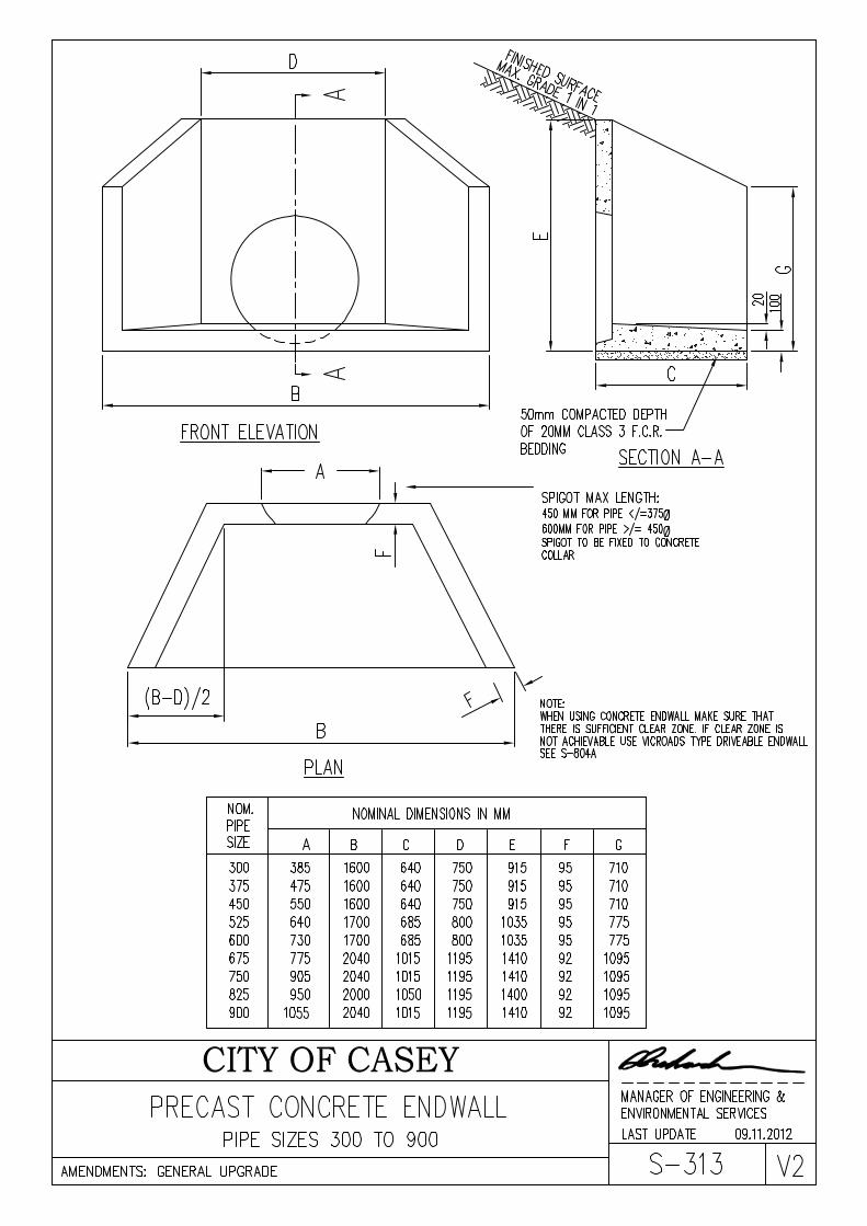
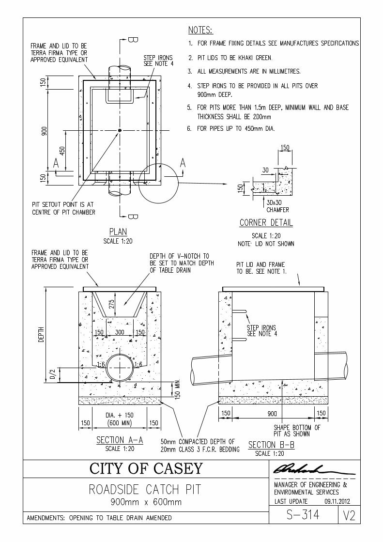
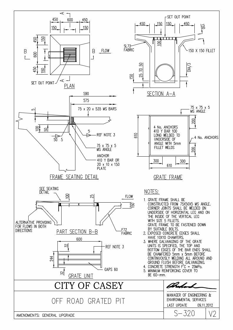
RECTANGULAR PRE-CAST PITS INSTALLATION PROCEDURE 1. Excavation
The excavation shall provide a clearance from all external faces of the pit to each face of the
excavation of not less than 300mm.
2. Bedding
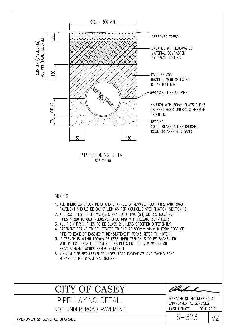
Bedding shall be 20mm class 3 F.C.R, placed and compacted to a thickness not less than 75mm. 3. Backfilling
All pits are to be backfilled with clean granular or friable material. The backfilling shall be placed in layers not exceeding 300mm loose in thickness and compacted to refusal using hand held mechanical equipment.
4. Pipe Connections
A concrete bandage is to be placed for the full circumference of the pipe on the external walls of the pit. A cement mortar mix is to be used on the internal walls.
5. Shaping of Floor
A semi circular section transitioning from the size of the outlet pipe to the size of the inlet pipe shall be constructed in all pits using mass concrete. Generally the shape shall be the same as specified for insitu pits.

RECTANGULAR PRE-CAST PITS INSTALLATION PROCEDURE 1. Excavation
The excavation shall provide a clearance from all external faces of the pit to each face of the
excavation of not less than 300mm.
2. Bedding
Bedding shall be 20mm class 3 F.C.R, placed and compacted to a thickness not less than 75mm. 3. Backfilling
All pits are to be backfilled with clean granular or friable material. The backfilling shall be placed in layers not exceeding 300mm loose in thickness and compacted to refusal using hand held mechanical equipment.
4. Pipe Connections
A concrete bandage is to be placed for the full circumference of the pipe on the external walls of the pit. A cement mortar mix is to be used on the internal walls.
5. Shaping of Floor
A semi circular section transitioning from the size of the outlet pipe to the size of the inlet pipe shall be constructed in all pits using mass concrete. Generally the shape shall be the same as specified for insitu pits.
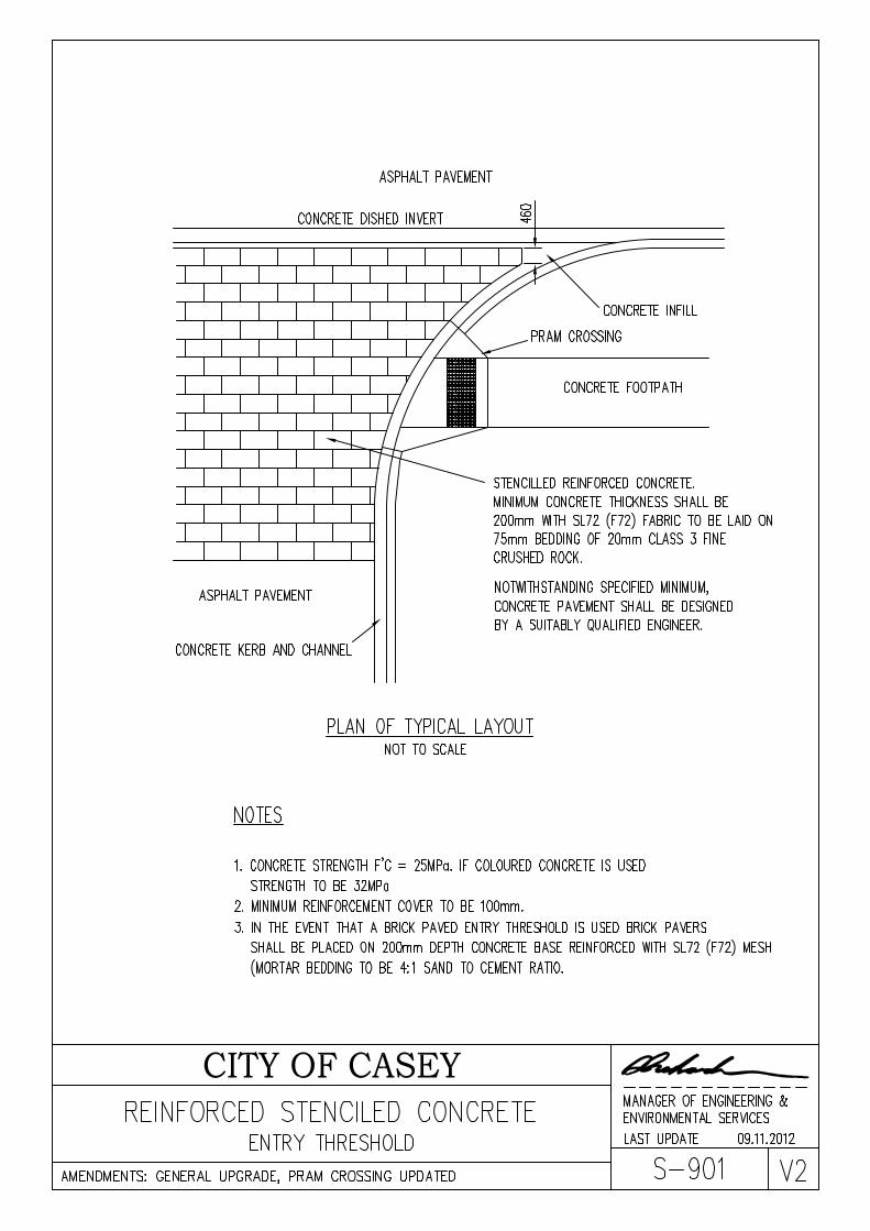
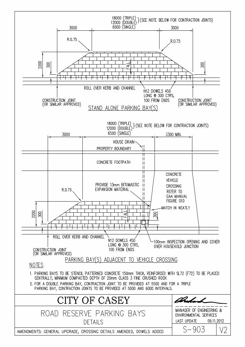
CONCRETE PAVING
NOVEMBER 2012
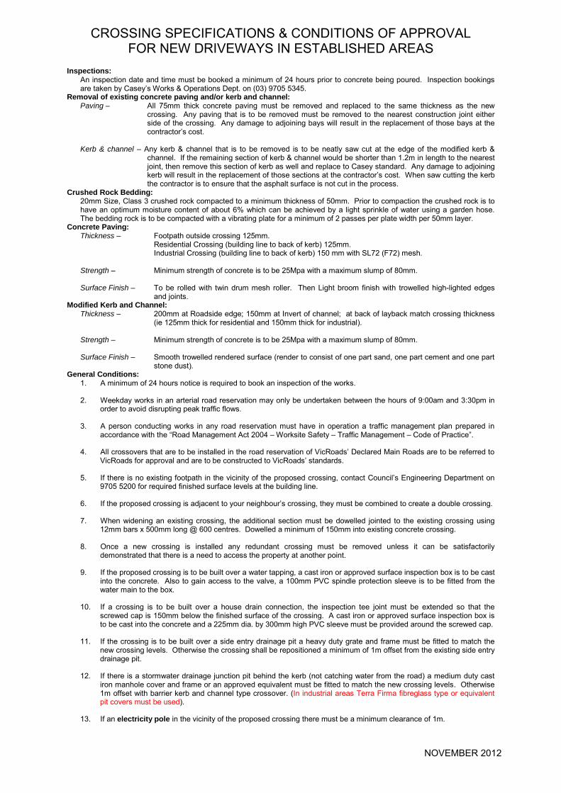
CROSSING SPECIFICATIONS & CONDITIONS OF APPROVAL FOR NEW DRIVEWAYS IN ESTABLISHED AREAS
Inspections:
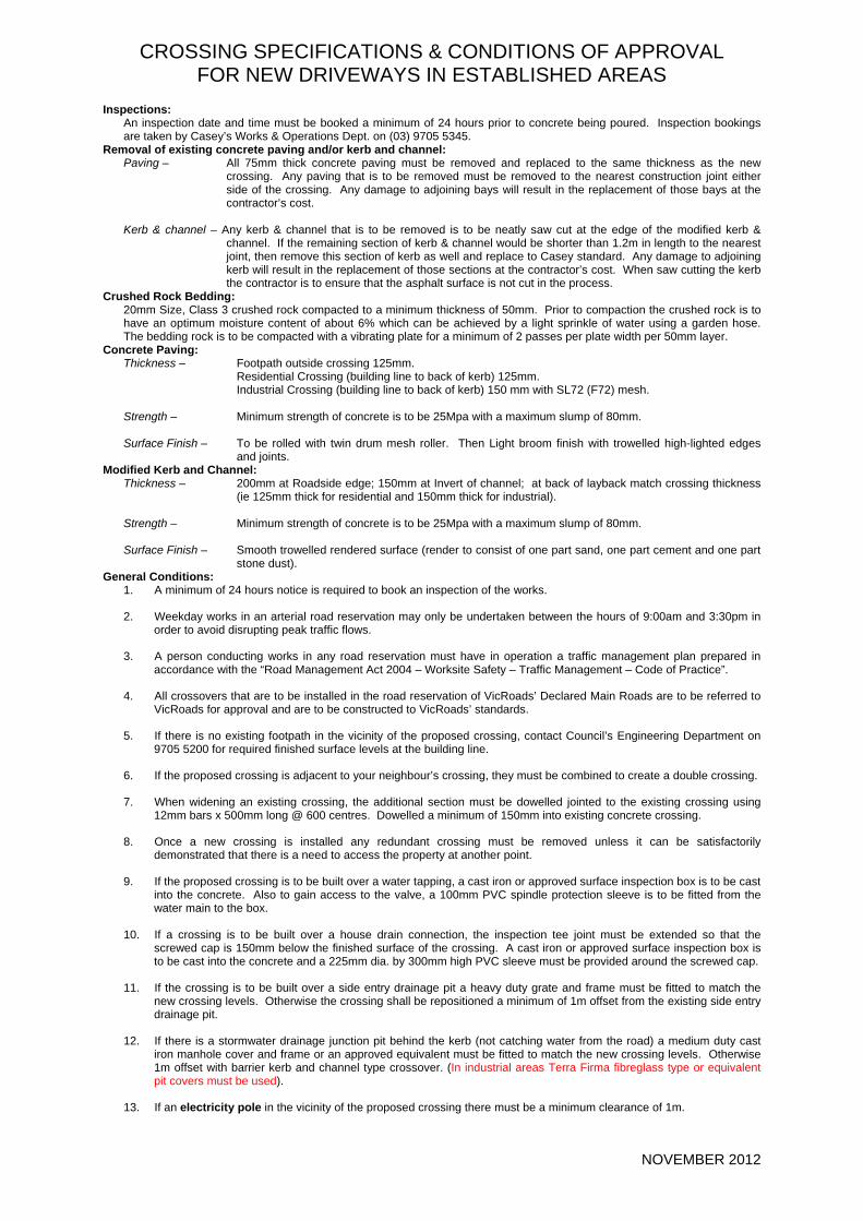
An inspection date and time must be booked a minimum of 24 hours prior to concrete being poured. Inspection bookings are taken by Casey’s Works & Operations Dept. on (03) 9705 5345.
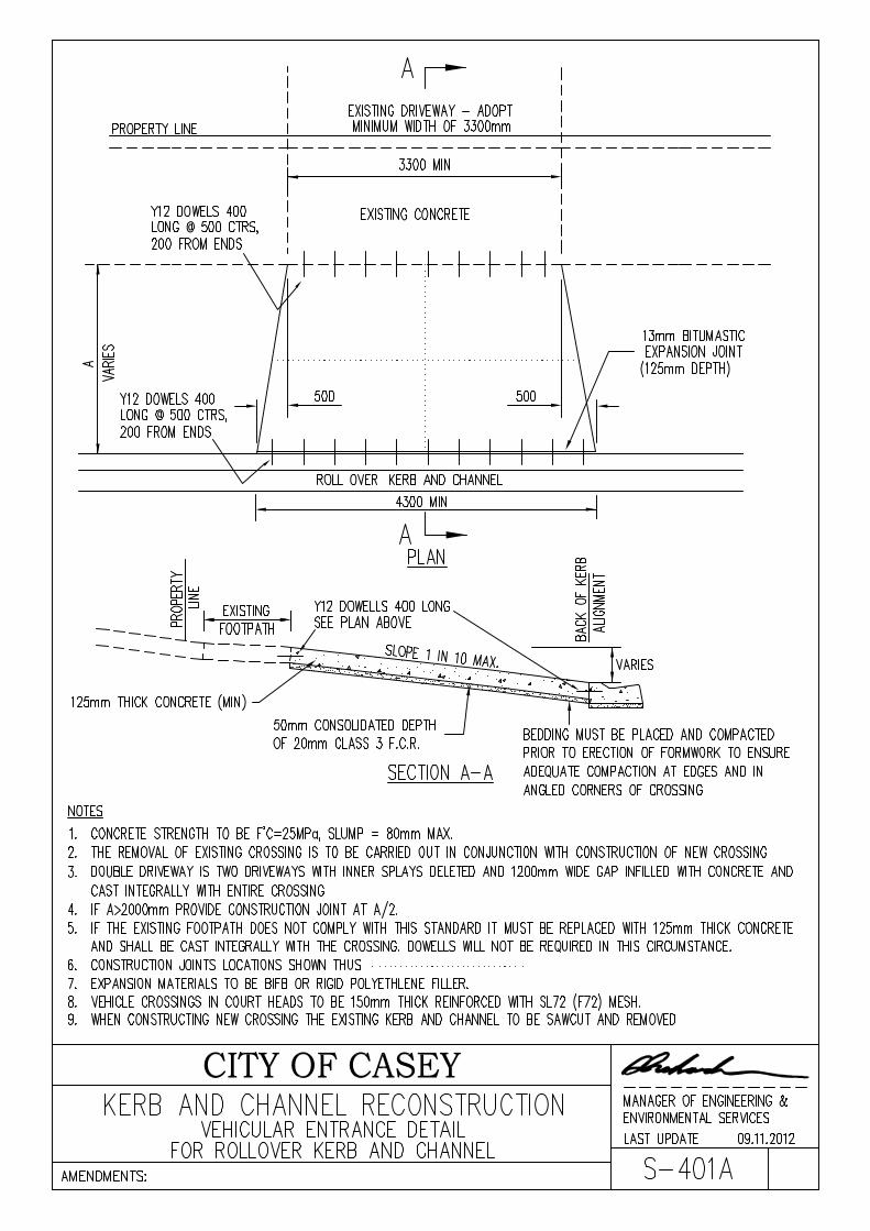
Removal of existing concrete paving and/or kerb and channel: Paving – All 75mm thick concrete paving must be removed and replaced to the same thickness as the new
crossing. Any paving that is to be removed must be removed to the nearest construction joint either side of the crossing. Any damage to adjoining bays will result in the replacement of those bays at the contractor’s cost.
Kerb & channel – Any kerb & channel that is to be removed is to be neatly saw cut at the edge of the modified kerb &
channel. If the remaining section of kerb & channel would be shorter than 1.2m in length to the nearest joint, then remove this section of kerb as well and replace to Casey standard. Any damage to adjoining kerb will result in the replacement of those sections at the contractor’s cost. When saw cutting the kerb the contractor is to ensure that the asphalt surface is not cut in the process.
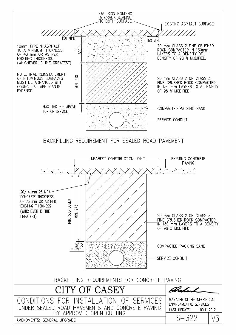
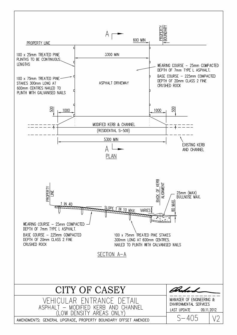
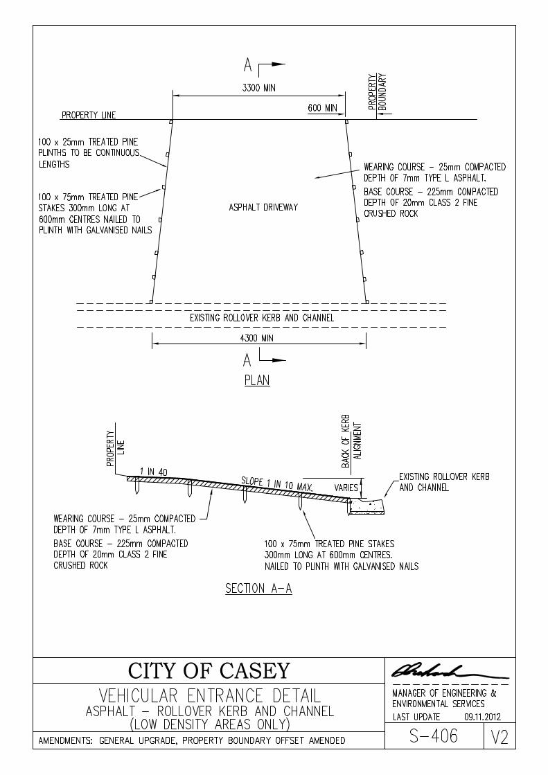
Crushed Rock Bedding: 20mm Size, Class 3 crushed rock compacted to a minimum thickness of 50mm. Prior to compaction the crushed rock is to have an optimum moisture content of about 6% which can be achieved by a light sprinkle of water using a garden hose. The bedding rock is to be compacted with a vibrating plate for a minimum of 2 passes per plate width per 50mm layer.
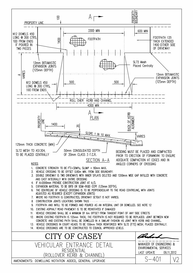
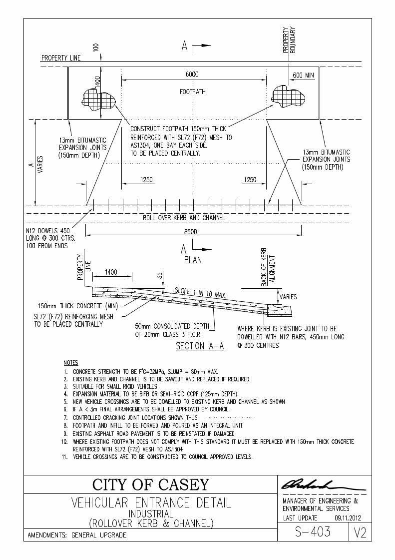
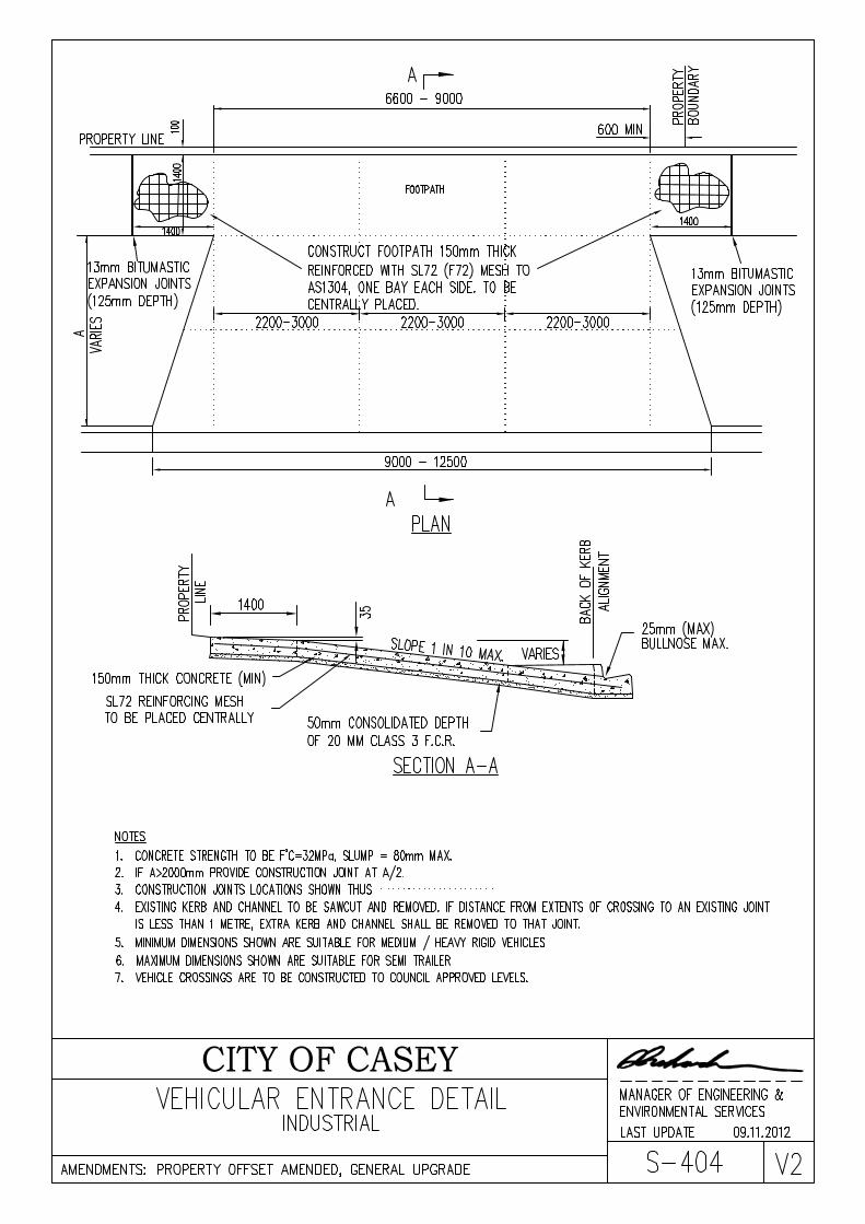
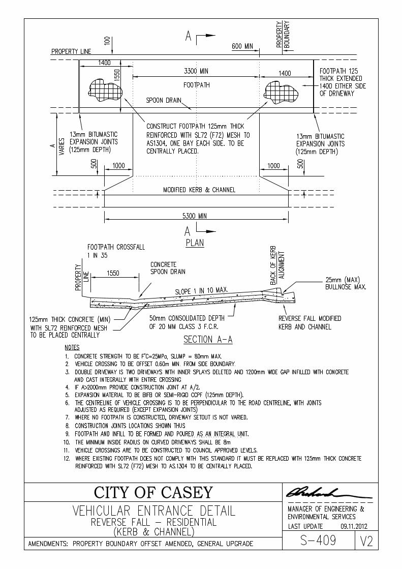
Concrete Paving: Thickness – Footpath outside crossing 125mm.
Residential Crossing (building line to back of kerb) 125mm. Industrial Crossing (building line to back of kerb) 150 mm with SL72 (F72) mesh. Strength – Minimum strength of concrete is to be 25Mpa with a maximum slump of 80mm. Surface Finish – To be rolled with twin drum mesh roller. Then Light broom finish with trowelled high-lighted edges
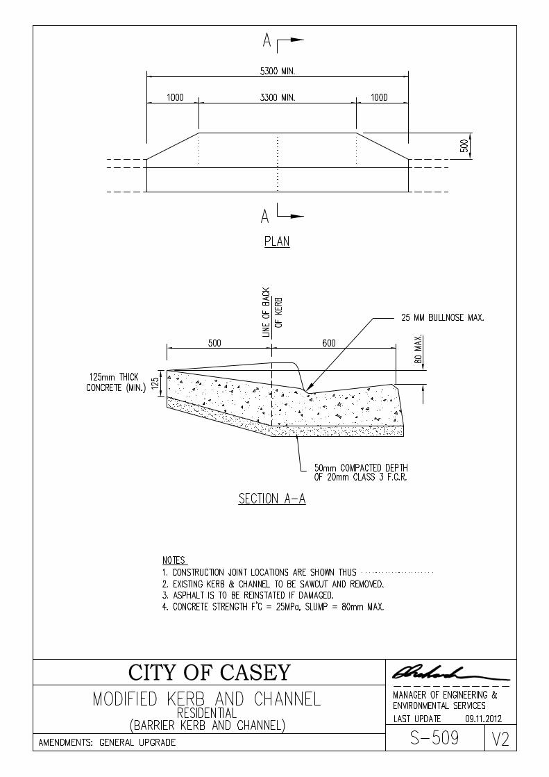
and joints. Modified Kerb and Channel:
Thickness – 200mm at Roadside edge; 150mm at Invert of channel; at back of layback match crossing thickness (ie 125mm thick for residential and 150mm thick for industrial).
Strength – Minimum strength of concrete is to be 25Mpa with a maximum slump of 80mm. Surface Finish – Smooth trowelled rendered surface (render to consist of one part sand, one part cement and one part
stone dust). General Conditions:
1. A minimum of 24 hours notice is required to book an inspection of the works.
2. Weekday works in an arterial road reservation may only be undertaken between the hours of 9:00am and 3:30pm in order to avoid disrupting peak traffic flows.
3. A person conducting works in any road reservation must have in operation a traffic management plan prepared in accordance with the “Road Management Act 2004 – Worksite Safety – Traffic Management – Code of Practice”.
4. All crossovers that are to be installed in the road reservation of VicRoads’ Declared Main Roads are to be referred to VicRoads for approval and are to be constructed to VicRoads’ standards.
5. If there is no existing footpath in the vicinity of the proposed crossing, contact Council’s Engineering Department on 9705 5200 for required finished surface levels at the building line.
6. If the proposed crossing is adjacent to your neighbour’s crossing, they must be combined to create a double crossing.
7. When widening an existing crossing, the additional section must be dowelled jointed to the existing crossing using 12mm bars x 500mm long @ 600 centres. Dowelled a minimum of 150mm into existing concrete crossing.
8. Once a new crossing is installed any redundant crossing must be removed unless it can be satisfactorily demonstrated that there is a need to access the property at another point.
9. If the proposed crossing is to be built over a water tapping, a cast iron or approved surface inspection box is to be cast into the concrete. Also to gain access to the valve, a 100mm PVC spindle protection sleeve is to be fitted from the water main to the box.
10. If a crossing is to be built over a house drain connection, the inspection tee joint must be extended so that the screwed cap is 150mm below the finished surface of the crossing. A cast iron or approved surface inspection box is to be cast into the concrete and a 225mm dia. by 300mm high PVC sleeve must be provided around the screwed cap.
11. If the crossing is to be built over a side entry drainage pit a heavy duty grate and frame must be fitted to match the new crossing levels. Otherwise the crossing shall be repositioned a minimum of 1m offset from the existing side entry drainage pit.
12. If there is a stormwater drainage junction pit behind the kerb (not catching water from the road) a medium duty cast iron manhole cover and frame or an approved equivalent must be fitted to match the new crossing levels. Otherwise 1m offset with barrier kerb and channel type crossover. (In industrial areas Terra Firma fibreglass type or equivalent pit covers must be used).
13. If an electricity pole in the vicinity of the proposed crossing there must be a minimum clearance of 1m.

NOVEMBER 2012
CROSSING SPECIFICATIONS & CONDITIONS OF APPROVAL FOR NEW DRIVEWAYS IN ESTABLISHED AREAS
Inspections:
An inspection date and time must be booked a minimum of 24 hours prior to concrete being poured. Inspection bookings are taken by Casey’s Works & Operations Dept. on (03) 9705 5345.
Removal of existing concrete paving and/or kerb and channel: Paving – All 75mm thick concrete paving must be removed and replaced to the same thickness as the new
crossing. Any paving that is to be removed must be removed to the nearest construction joint either side of the crossing. Any damage to adjoining bays will result in the replacement of those bays at the contractor’s cost.
Kerb & channel – Any kerb & channel that is to be removed is to be neatly saw cut at the edge of the modified kerb &
channel. If the remaining section of kerb & channel would be shorter than 1.2m in length to the nearest joint, then remove this section of kerb as well and replace to Casey standard. Any damage to adjoining kerb will result in the replacement of those sections at the contractor’s cost. When saw cutting the kerb the contractor is to ensure that the asphalt surface is not cut in the process.
Crushed Rock Bedding: 20mm Size, Class 3 crushed rock compacted to a minimum thickness of 50mm. Prior to compaction the crushed rock is to have an optimum moisture content of about 6% which can be achieved by a light sprinkle of water using a garden hose. The bedding rock is to be compacted with a vibrating plate for a minimum of 2 passes per plate width per 50mm layer.
Concrete Paving: Thickness – Footpath outside crossing 125mm.
Residential Crossing (building line to back of kerb) 125mm. Industrial Crossing (building line to back of kerb) 150 mm with SL72 (F72) mesh. Strength – Minimum strength of concrete is to be 25Mpa with a maximum slump of 80mm. Surface Finish – To be rolled with twin drum mesh roller. Then Light broom finish with trowelled high-lighted edges
and joints. Modified Kerb and Channel:
Thickness – 200mm at Roadside edge; 150mm at Invert of channel; at back of layback match crossing thickness (ie 125mm thick for residential and 150mm thick for industrial).
Strength – Minimum strength of concrete is to be 25Mpa with a maximum slump of 80mm. Surface Finish – Smooth trowelled rendered surface (render to consist of one part sand, one part cement and one part
stone dust). General Conditions:
1. A minimum of 24 hours notice is required to book an inspection of the works.
2. Weekday works in an arterial road reservation may only be undertaken between the hours of 9:00am and 3:30pm in order to avoid disrupting peak traffic flows.
3. A person conducting works in any road reservation must have in operation a traffic management plan prepared in accordance with the “Road Management Act 2004 – Worksite Safety – Traffic Management – Code of Practice”.
4. All crossovers that are to be installed in the road reservation of VicRoads’ Declared Main Roads are to be referred to VicRoads for approval and are to be constructed to VicRoads’ standards.
5. If there is no existing footpath in the vicinity of the proposed crossing, contact Council’s Engineering Department on 9705 5200 for required finished surface levels at the building line.
6. If the proposed crossing is adjacent to your neighbour’s crossing, they must be combined to create a double crossing.
7. When widening an existing crossing, the additional section must be dowelled jointed to the existing crossing using 12mm bars x 500mm long @ 600 centres. Dowelled a minimum of 150mm into existing concrete crossing.
8. Once a new crossing is installed any redundant crossing must be removed unless it can be satisfactorily demonstrated that there is a need to access the property at another point.
9. If the proposed crossing is to be built over a water tapping, a cast iron or approved surface inspection box is to be cast into the concrete. Also to gain access to the valve, a 100mm PVC spindle protection sleeve is to be fitted from the water main to the box.
10. If a crossing is to be built over a house drain connection, the inspection tee joint must be extended so that the screwed cap is 150mm below the finished surface of the crossing. A cast iron or approved surface inspection box is to be cast into the concrete and a 225mm dia. by 300mm high PVC sleeve must be provided around the screwed cap.
11. If the crossing is to be built over a side entry drainage pit a heavy duty grate and frame must be fitted to match the new crossing levels. Otherwise the crossing shall be repositioned a minimum of 1m offset from the existing side entry drainage pit.
12. If there is a stormwater drainage junction pit behind the kerb (not catching water from the road) a medium duty cast iron manhole cover and frame or an approved equivalent must be fitted to match the new crossing levels. Otherwise 1m offset with barrier kerb and channel type crossover. (In industrial areas Terra Firma fibreglass type or equivalent pit covers must be used).
13. If an electricity pole in the vicinity of the proposed crossing there must be a minimum clearance of 1m.

CONCRETE KERB & CHANNEL
PROPERTY DRAINAGE
PAVING