Embed Size (px)
Citation preview

07-01-15
SECTION 26 32 13ENGINE GENERATORS
SPEC WRITER NOTE:Delete between //----// if not applicable to project. Also delete any other item or paragraph not applicable in the section and renumber the paragraphs.
PART 1 - GENERAL
1.1 DESCRIPTION
A. This section specifies the furnishing, installation, connection, and
testing of the //low-voltage// //medium-voltage// engine generators.
1.2 RELATED WORK
//A. Section 03 30 00, CAST-IN-PLACE CONCRETE: Requirements for concrete
equipment pads.//
//B. Section 13 05 41, SEISMIC RESTRAINT REQUIREMENTS FOR NON-STRUCTURAL
COMPONENTS: Requirement for seismic restraint for nonstructural
components.//
C. Section 26 05 11, REQUIREMENTS FOR ELECTRICAL INSTALLATIONS:
Requirements that apply to all sections of Division 26.
D. Section 26 05 13, MEDIUM-VOLTAGE CABLES: Medium-voltage cables.
E. Section 26 05 19, LOW-VOLTAGE ELECTRICAL POWER CONDUCTORS AND CABLES:
Low-voltage conductors.
F. Section 26 05 26, GROUNDING AND BONDING FOR ELECTRICAL SYSTEMS:
Requirements for personnel safety and to provide a low impedance path
for possible ground fault currents.
G. Section 23 05 41, NOISE AND VIBRATION CONTROL FOR HVAC PIPING AND
EQUIPMENT: Requirements for pipe and equipment support and noise
control.
H. Section 26 05 73, OVERCURRENT PROTECTIVE DEVICE COORDINATION STUDY:
Short circuit and coordination study, and requirements for a coordinated
electrical system.
I. Section 23 07 11, HVAC, PLUMBING, AND BOILER PLANT INSULATION:
Requirements for hot piping and equipment insulation.
J. Section 25 10 10, ADVANCED UTILITY METERING: Requirements for electrical
metering.
//K. Section 26 13 13, MEDIUM-VOLTAGE CIRCUIT BREAKER SWITCHGEAR:
Requirements for medium-voltage circuit breaker switchgear for use with
medium-voltage generators.//
26 32 13 - 1

07-01-15
//L. Section 26 23 00, LOW-VOLTAGE SWITCHGEAR: Requirements for secondary
distribution switchgear.//
//M. Section 26 23 13, GENERATOR PARALLELING CONTROLS: Requirements for
generator paralleling.//
//N. Section 26 24 13, DISTRIBUTION SWITCHBOARDS: Requirements for secondary
distribution switchboards.//
O. Section 26 36 23, AUTOMATIC TRANSFER SWITCHES: Requirements for
automatic transfer switches for use with engine generators.
1.3 QUALITY ASSURANCE
A. Refer to Paragraph, QUALIFICATIONS (PRODUCTS AND SERVICES), in Section
26 05 11, REQUIREMENTS FOR ELECTRICAL INSTALLATIONS.
SPEC WRITER NOTE: Edit the paragraph below to match locally available manufacturer’s maintenance and support capability.
B. A factory-authorized representative shall be capable of providing
emergency maintenance and repairs at the project site within //4// // //
hours maximum of notification.
1.4 FACTORY TESTS
A. Factory Tests shall be performed in the factory by the equipment
manufacturer. Factory Tests shall comply with all Factory Tests
requirements stated in Section 26 05 11, REQUIREMENTS FOR ELECTRICAL
INSTALLATIONS, and the requirements stated in this section.
B. Load Test: Shall include two hours while the engine generator is
delivering 100% of the specified kW, and four hours while the engine
generator is delivering 80% of the specified kW. During this test,
record the following data at 20-minute intervals:
Time Engine RPM Oil Temperature Out
kW Water Temperature In Fuel Pressure
Voltage Water Temperature Out Oil Pressure
Amperes Oil Temperature In Ambient Temperature
C. Cold Start Test: Record time required for the engine generator to
develop specified voltage, frequency, and kW load from a standstill
condition with engine at ambient temperature.
D. The manufacturer shall furnish fuel, load banks, testing instruments,
and all other equipment necessary to perform these tests.
26 32 13 - 2

07-01-15
1.5 SUBMITTALS
A. Submit six copies of the following in accordance with Section 26 05 11,
REQUIREMENTS FOR ELECTRICAL INSTALLATIONS.
1. Shop Drawings:
a. Submit sufficient information to demonstrate compliance with
drawings and specifications.
b. Scaled drawings, showing plan views, side views, elevations, and
cross-sections.
SPEC WRITER NOTE: Include the following paragraph for projects in seismic areas of moderate-high, high and very high seismicities as listed in Table 4 of VA Handbook H-18-8, Seismic Design Requirements. Coordinate with the structural engineer.
//c. Certification from the manufacturer that a representative engine
generator has been seismically tested to International Building
Code requirements. Certification shall be based upon simulated
seismic forces on a shake table or by analytical methods, but not
by experience data or other methods.//
2. Diagrams:
a. Control system diagrams, control sequence diagrams or tables,
wiring diagrams, interconnections diagrams (between engine
generators, automatic transfer switches, paralleling switchgear,
local control cubicles, remote annunciator panels, and fuel
storage tanks, as applicable), and other like items.
3. Technical Data:
a. Published ratings, catalog cuts, pictures, and manufacturer’s
specifications for engine generator, governor, voltage regulator,
radiator, muffler, dampers, day tank, pumps, fuel tank, batteries
and charger, jacket heaters, torsional vibration, and control and
supervisory equipment.
b. Description of operation.
c. Short-circuit current capacity and subtransient reactance.
d. Sound power level data.
SPEC WRITER NOTE: Edit or include the paragraph below to conform with project requirements.
26 32 13 - 3

07-01-15
//e. Vibration isolation system performance data from no-load to full-
load. This must include seismic qualification of the engine
generator mounting, base, and vibration isolation.//
4. Calculations:
a. Calculated performance derations appropriate to installed
environment.
5. Manuals:
a. When submitting the shop drawings, submit complete maintenance and
operating manuals, to include the following:
1) Technical data sheets.
2) Wiring diagrams.
3) Include information for testing, repair, troubleshooting, and
factory recommended periodic maintenance procedures and
frequency.
4) Provide a replacement and spare parts list. Include a list of
tools and instruments for testing and maintenance purposes.
b. If changes have been made to the maintenance and operating manuals
originally submitted, submit updated maintenance and operating
manuals two weeks prior to the final inspection.
6. Test Reports:
a. Submit certified factory test reports for approval.
b. Submit field test reports two weeks prior to the final inspection.
7. Certifications:
a. Prior to fabrication of the engine generator, submit the following
for approval:
1) A certification in writing that an engine generator of the same
model and configuration, with the same bore, stroke, number of
cylinders, and equal or higher kW/kVA ratings as the proposed
engine generator, has been operating satisfactorily with
connected loads of not less than 75% of the specified kW/kVA
rating, for not fewer than 2,000 hours without any failure of a
crankshaft, camshaft, piston, valve, injector, or governor
system.
2) A certification in writing that devices and circuits will be
incorporated to protect the voltage regulator and other
components of the engine generator during operation at speeds
other than the rated RPM while performing maintenance. Submit
thorough descriptions of any precautions necessary to protect
26 32 13 - 4

07-01-15
the voltage regulator and other components of the system during
operation of the engine generator at speeds other than the
rated RPM.
3) A certification from the engine manufacturer stating that the
engine exhaust emissions meet the applicable federal, state,
and local regulations and restrictions. At a minimum, this
certification shall include emission factors for criteria
pollutants including nitrogen oxides, carbon monoxide,
particulate matter, sulfur dioxide, non-methane hydrocarbon,
and hazardous air pollutants (HPAs).
b. Prior to installation of the engine generator at the job site,
submit certified factory test data.
c. Two weeks prior to the final inspection, submit the following.
1) Certification by the manufacturer that the engine generators
conform to the requirements of the drawings and specifications.
2) Certification by the Contractor that the engine generators have
been properly installed, adjusted, and tested.
1.6 STORAGE AND HANDLING
A. Engine generators shall withstand shipping and handling stresses in
addition to the electrical and mechanical stresses which occur during
operation of the system. Protect radiator core with wood sheet.
B. Store the engine generators in a location approved by the //Resident
Engineer// //COR//.
1.7 JOB CONDITIONS
A. Job conditions shall conform to the arrangements and details shown on
the drawings. The dimensions, enclosures, and arrangements of the
engine generator system shall permit the operating personnel to safely
and conveniently operate and maintain the system in the space designated
for installation.
1.8 APPLICABLE PUBLICATIONS
A. Publications listed below (including amendments, addenda, revisions,
supplements, and errata) form a part of this specification to the extent
referenced. Publications are referenced in the text by designation only.
B. American National Standards Institute (ANSI):
C37.50-07...............Low-Voltage AC Power Circuit Breakers Used In
Enclosures-Test Procedures
C39.1-81 (R1992) .......Requirements for Electrical Analog Indicating
Instruments
26 32 13 - 5

07-01-15
C. American Society of Testing Materials (ASTM):
A53/A53M-10.............Standard Specification for Pipe, Steel, Black,
and Hot–Dipped, Zinc Coated Welded and Seamless
B88-09..................Specification for Seamless Copper Water Tube
B88M-11.................Specification for Seamless Copper water Tube
(Metric)
D975-11b................Diesel Fuel Oils
D. Institute of Electrical and Electronic Engineers (IEEE):
C37.13-08...............Low Voltage AC Power Circuit Breakers Used In
Enclosures
C37.90.1-02.............Surge Withstand Capability (SWC) Tests for
Relays and Relay Systems Associated with
Electric Power Apparatus
E. International Code Council (ICC):
IBC-12..................International Building Code
F. National Electrical Manufacturers Association (NEMA):
ICS 6-06................Enclosures
ICS 4-10................Application Guideline for Terminal Blocks
MG 1-11.................Motor and Generators
MG 2-07.................Safety Standard and Guide for Selection,
Installation and Use of Electric Motors and
Generators
PB 2-11.................Dead-Front Distribution Switchboards
250-08..................Enclosures for Electrical Equipment (1000 Volts
Maximum)
G. National Fire Protection Association (NFPA):
30-12...................Flammable and Combustible Liquids Code
37-10...................Installations and Use of Stationary Combustion
Engine and Gas Turbines
70-11...................National Electrical Code (NEC)
99-12...................Health Care Facilities
110-10..................Standard for Emergency and Standby Power Systems
H. Underwriters Laboratories, Inc. (UL):
50-07...................Enclosures for Electrical Equipment
142-06..................Steel Aboveground Tanks for Flammable and
Combustible Liquids
467-07..................Grounding and Bonding Equipment
26 32 13 - 6
07-01-15
489-09..................Molded-Case Circuit Breakers, Molded-Case
Switches and Circuit-Breaker Enclosures
508-99..................Industrial Control Equipment
891-05..................Switchboards
1236-06.................Battery Chargers for Charging Engine-Starter
Batteries
2085-97.................Insulated Aboveground Tanks for Flammable and
Combustible Liquids
2200-98.................Stationary Engine Generator Assemblies
SPEC WRITER NOTE: Delete between // ---- // if not applicable to project. Also delete any other item or paragraph not applicable to the section and renumber the paragraphs.
PART 2 - PRODUCTS
2.1 GENERAL REQUIREMENTS
A. The engine generator system shall be in accordance with NFPA, UL, NEMA
and ANSI, and as specified herein.
B. Provide a factory-assembled, wired (except for field connections),
complete, fully automatic engine generator system, as well as all
associate equipment and devices intended for the operating, control,
monitoring, and remote manual stop functions.
SPEC WRITER NOTE: Make choices from the options below. If more than one engine generator type is part of the project, provide independent parameter schedules as necessary.
C. Engine Generator Parameter Schedule:
1. Power Rating: //Limited Running Time// //Emergency Standby//
2. Voltage: //120/208V// //277/480V// //4160V// //12470V//
//13200V// //13800V// // V//
3. Rated Power: //_____// kW //_____// kVA continuous)
4. Power Factor: //0.8// //_____// lagging
5. Engine Generator Application: //stand-alone// //parallel with utility
source// //parallel with other generators on an isolated bus//
//parallel with other engine generators and a utility source//
6. Fuel: diesel
7. Voltage Regulation: + 2% (maximum) (No Load to Full Load) (standalone
applications)
8. Phases: //3 Phase, Wye// //3 Phase, Delta//
26 32 13 - 7

07-01-15
9. Each component of the engine generator system shall be capable of
operating at // // meters (//____// feet) above sea level //in a
ventilated room// which will have average ambient air temperature
ranging from a minimum of // // °C (// // °F) in winter to maximum
of // // °C (// // °F) in summer.
D. Assemble, connect, and wire the engine generator at the factory so that
only the external connections need to be made at the construction site.
E. Engine Generator Unit shall be factory-painted with manufacturer's
primer and standard finishes.
F. Connections between components of the system shall conform to the
recommendations of the manufacturer.
G. Couplings, shafts, and other moving parts shall be enclosed and guarded.
Guards shall be metal, ruggedly constructed, rigidly fastened, and
readily removable for convenient servicing of the equipment without
disassembling any pipes and fittings.
H. Engine generator shall have the following features:
1. Factory-mounted on a common, rigid, welded, structural steel base.
2. Engine generator shall be statically and dynamically balanced so that
the maximum vibration in the horizontal, vertical, and axial
directions shall be limited to 0.15 mm (0.0059 inch), with an overall
velocity limit of 24 mm/sec (0.866 inch per second) RMS, for all
speeds.
3. The isolators shall be constrained with restraints capable of
withstanding static forces in any direction equal to twice the weight
of the supported equipment.
4. Shall be capable of operating satisfactorily as specified for not
fewer than 10,000 hours between major overhauls.
SPEC WRITER NOTE: Edit the paragraph below to conform to project requirements.
I. Each engine generator specified for parallel operation shall be
configured for automatic parallel operation.
2.2 ENGINE
A. The engine shall be coupled directly to a generator.
B. Minimum four cylinders.
C. The engine shall be able to start in a 4.5 ˚C (40 ˚F) ambient
temperature while using No. 2 diesel fuel oil without the use of
starting aids such as glow plugs and ether injections.
26 32 13 - 8
07-01-15
D. The engine shall be equipped with electric heater for maintaining the
coolant temperature between 32-38 °C (90-100 °F), or as recommended by
the manufacturer.
1. Install thermostatic controls, contactors, and circuit breaker-
protected circuits for the heaters.
2. The heaters shall operate continuously except while the engine is
operating or the water temperature is at the predetermined level.
2.3 GOVERNOR
A. Isochronous, electronic type.
B. Steady-state speed band at 60 Hz shall not exceed plus or minus 0.33%.
2.4 LUBRICATION OIL SYSTEM
A. Pressurized type.
B. Positive-displacement pump driven by engine crankshaft.
C. Full-flow strainer and full-flow or by-pass filters.
D. Filters shall be cleanable or replaceable type and shall remove
particles as small as 3 microns without removing the additives in the
oil. For by-pass filters, flow shall be diverted without flow
interruption.
E. Extend lube oil sump drain line out through the skid base and terminate
it with a drain valve and plug.
SPEC WRITER NOTE: Include the paragraph below to conform to project requirements.
//F. Provide a 120-volt oil heater for exterior engine generator.//
2.5 FUEL SYSTEM
A. Main fuel storage tank(s) shall comply with the requirements of Section
23 10 00, FACILITY FUEL SYSTEMS.
B. Shall comply with NFPA 37 and NFPA 30, and have the following features:
1. Injection pump(s) and nozzles.
2. Plungers shall be carefully lapped for precision fit and shall not
require any packing.
3. Filters or screens that require periodic cleaning or replacement
shall not be permitted in the injection system assemblies.
4. Return surplus oil from the injectors to the main storage tank by
gravity or a pump.
5. Filter System:
a. Dual primary filters shall be located between the main fuel oil
storage and day tank.
26 32 13 - 9

07-01-15
b. Secondary filters (engine-mounted) shall be located such that the
oil will be thoroughly filtered before it reaches the injection
system assemblies.
c. Filters shall be cleanable or replaceable type and shall entrap
and remove water from oil as recommended by the engine
manufacturer.
C. Day Tank:
1. Each engine generator shall be provided with a welded steel
//separate self-supporting// //integral// day tank with double-wall
fuel containment.
2. Each day tank shall have capacity to supply fuel to the engine for
a //4-hour// period at 100% rated load without being refilled,
including fuel that is returned to the main fuel storage tank. The
calculation of the capacity of each day tank shall incorporate the
requirement to stop the supply of fuel into the day tank at 90% of
the ultimate volume of the tank.
3. Secure, pipe, and connect the tank adequately for maximum protection
from fire hazards, including oil leaks.
4. Incorporate a vent, drain cock, shutoff cocks, and gauge glass.
Terminate the vent piping outdoors with mushroom vent cap.
5. Incorporate a float switch on the day tank to control the fuel oil
transfer pump and to actuate an alarm in the engine generator control
cubicle when the oil level in the tank drops below the level at which
the transfer pump should start to refill the tank.
a. The float switch contacts controlling the fuel oil transfer pump
shall be set to energize the pump when the liquid level in the
tank reaches one-third of the total volume of the tank.
b. The float switch contacts that actuate the low fuel oil day tank
alarm device shall be set to alarm and energize the second fuel
transfer pump when the liquid level in the tank reaches one-
quarter of the total volume of the tank.
6. Day tank and engine supply line elevations shall be below the
elevation of the injector return outlet on the engine.
D. Fuel Transfer Pump - Main Storage Tank to Day Tank(s):
1. Electric motor-driven, duplex arrangement, close-coupled, single-
stage, positive-displacement type with built-in pressure relief
valves. When the fuel is used for cooling components of the fuel
26 32 13 - 10

07-01-15
injection system, the engine's fuel return line shall be returned to
the main storage tank, rather than the day tank.
2. Include a heavy-duty automatic alternator and H-O-A switch to
alternate sequence of pumps. Pumps shall be controlled with the float
switch on the day tank and H-O-A selector switch such that the day
tank will be refilled automatically when the oil level lowers to the
low limit for the float switch. The H-O-A selector switches shall
enable the pumps to be operated manually at any time.
3. For all engines, the related transfer pump and its electrical and
plumbing connections shall be sized to provide a flow rate of at
least four times the engine's fuel pumping rate.
4. Provide a manually-operated, rotary-type transfer pump connected in
parallel with the electric motor-driven transfer pumps so that oil
can be pumped to the day tank while the electric motor-driven pumps
are inoperative.
E. Piping System: Black steel standard weight ASTM A-53 pipe and necessary
valves and pressure gauges between:
1. The engine and the day tank as shown on the drawings.
2. The day tank and the supply and return connections at the underground
storage tank as shown on the drawings. Connections at the engine
shall be made with flexible piping suitable for the fuel furnished.
SPEC WRITER NOTE: In the following paragraph delete the items enclosed by //_____// where the radiator will not be more than 3 M (10 feet) above the engine.
2.6 COOLING SYSTEM
A. Liquid-cooled, closed loop, with // fin-tube radiator mounted on the
engine generator, // fin-tube remote radiator, // and integral engine
driven circulating pump, // as shown on the drawings.
B. Cooling capacity shall not be less than the cooling requirements of the
engine generator and its lubricating oil while operating continuously at
100% of its specified rating.
//C. Water circulating pumps shall be the centrifugal type driven by engine.
Incorporate pressure relief devices where required to prevent excessive
pressure increase after the engine stops. //
D. Coolant shall be extended-life antifreeze solution, 50% ethylene glycol
and 50% soft water, with corrosion inhibitor additive as recommended by
the manufacturer.
26 32 13 - 11

07-01-15
E. Fan shall be driven by // multiple belts from engine shaft // a totally
enclosed electric motor //.
F. Coolant hoses shall be flexible, per manufacturer's recommendation.
G. Self-contained thermostatic-control valve shall modulate coolant flow to
maintain optimum constant coolant temperature, as recommended by the
engine manufacturer.
SPEC WRITER NOTE: Coordinate motor operated dampers provided in Division 23 with the engine generator.
H. Motor-Operated Dampers:
1. Dampers, which are provided under Section 23 31 00, HVAC DUCTS AND
CASINGS, shall be two-position, electric motor-operated.
2. Dampers shall open simultaneously with the starting of the diesel
engine and shall close simultaneously with the stopping of the diesel
engine.
SPEC WRITER NOTE: Include this paragraph when a remote radiator is used.
//I. Remote Radiator Enclosure:
1. Shall be rugged, tamperproof assemblies framed with steel channels,
angles, and braces. Provide fan shroud, fixed louvers, and bird
screens at both air intake and exhaust.
2. Shall be securely bolted together to facilitate future dismantling.
Carriage type bolts shall be used with the washers and locknuts on
the inside of the enclosures.
3. Door shall be leveled sheet steel attached with concealed or semi-
concealed hinges. Include a stop edge around the inside of the door
opening and a metal rod stop for 90 degree opening.
4. Anchor the enclosures to concrete bases with bolts, not less than 15
mm (0.5 inch) diameter.
5. Radiator fan motor shall be totally enclosed with guarded V-belt
drive and an adjustable mounting base.
6. Coolant piping shall be as recommended by the manufacturer.//
2.7 AIR INTAKE AND EXHAUST SYSTEMS
SPEC WRITER NOTE: Coordinate fresh air intake location with architectural drawings and make sure the air intake is located away from any exhaust gases to avoid entrainment of exhaust into the air intake.
26 32 13 - 12

07-01-15
A. Air Intake:
1. Provide an engine-mounted air cleaner with replaceable dry filter and
dirty filter indicator.
B. Exhaust System:
SPEC WRITER NOTE: Include the following paragraph only when the drawings show such an arrangement. Ensure that the exhaust gases leaving the engine generator are diffused properly into the airstream.
//1. Where a turbocharger is required, they shall be engine-mounted,
driven by the engine gases, securely braced against vibration and
adequately lubricated by the engine's filtered lubrication system. //
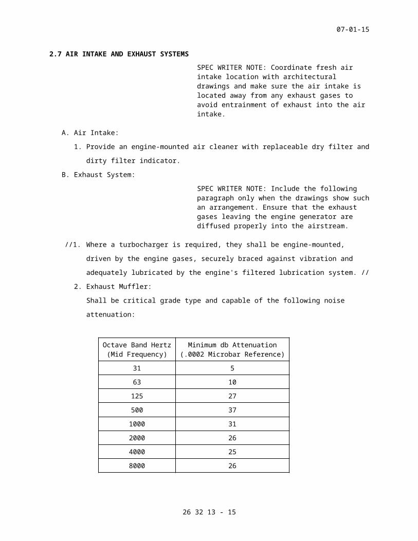
2. Exhaust Muffler:
Shall be critical grade type and capable of the following noise
attenuation:
Octave Band Hertz(Mid Frequency)
Minimum db Attenuation(.0002 Microbar Reference)
31 5
63 10
125 27
500 37
1000 31
2000 26
4000 25
8000 26
3. Pressure drop in the complete exhaust system shall be small enough
for satisfactory operation of the engine generator while it is
delivering 100% of its specified rating.
4. Exhaust pipe size from the engine to the muffler shall be as
recommended by the engine manufacturer. Pipe size from muffler to air
discharge shall be two pipe sizes larger than engine exhaust pipe.
5. Connections at the engine exhaust outlet shall be made with a
flexible exhaust pipe. Provide bolted type pipe flanges welded to
each end of the flexible section.
C. Condensate drain at muffler shall be made with schedule 40 black steel
pipe through a petcock.
26 32 13 - 13

07-01-15
D. Exhaust Piping and Supports: Black steel pipe, ASTM A-53 standard weight
with welded fittings. Spring type hangers, as specified in Section 23 05
41, NOISE AND VIBRATION CONTROL FOR HVAC PIPING AND EQUIPMENT, shall
support the pipe.
E. Insulation for Exhaust Pipe and Muffler:
1. Calcium silicate minimum 75 mm (3 inches) thick.
2. Insulation shall be as specified in Section 23 07 11, HVAC, PLUMBING,
AND BOILER PLANT INSULATION.
3. The installed insulation shall be covered with aluminum jacket 0.4 mm
(0.016 inch) thick. The jacket is to be held in place by bands of
0.38 mm (0.015 inch) thick by 15 mm (0.5 inch) wide aluminum.
4. Insulation and jacket are not required on flexible exhaust sections.
SPEC WRITER NOTE: Include the VA Standard Detail for engine generator exhaust on the drawings.
F. // Roof // Wall // Sleeves: Pipe sleeves (thimble) shall be Schedule 40
standard weight steel pipe. Flash exhaust pipe thimble through roof with
16 oz soft sheet copper, flanged, and made watertight under built-up
roofing and extended up around pipe thimble. The exhaust pipe shall be
positioned within the thimble by four 150 mm (6 inches) wide spiders
welded to the exhaust pipe.
G. Vertical exhaust piping shall be provided with a hinged, gravity-
operated, self-closing rain cover.
2.8 ENGINE STARTING SYSTEM
A. The engine starting system shall start the engine at any position of the
flywheel.
B. Electric cranking motor:
1. Shall be engine-mounted.
2. Shall crank the engine via a gear drive.
3. Rating shall be adequate for cranking the cold engine at the voltage
provided by the battery system, and at the required RPM during five
consecutive starting attempts of 10 seconds cranking each at
10-second intervals, for a total of 50 seconds of actual cranking
without damage (the fifth starting attempt will be manually initiated
upon failure of a complete engine cranking cycle).
C. Batteries shall be //nickel-cadmium// //lead-acid// high discharge rate
type.
26 32 13 - 14
07-01-15
1. Each battery cell shall have minimum and maximum electrolyte level
indicators and a flip-top flame arrestor vent cap.
2. Batteries shall have connector covers for protection against external
short circuits.
3. With the charger disconnected, the batteries shall have sufficient
capacity so that the total system voltage does not fall below 85% of
the nominal system voltage with the following demands:
Five consecutive starting attempts of 10 seconds cranking at 10
second intervals for a total of 50 seconds of actual cranking (the
fifth starting attempt will be manually initiated upon failure of a
complete engine cranking cycle).
4. Battery racks shall be metal with an alkali-resistant finish and
thermal insulation, and secured to the floor.
D. Battery Charger:
1. A current-limiting battery charger, conforming to UL 1236, shall be
provided and shall automatically recharge the batteries. The charger
shall be capable of an equalize-charging rate for recharging fully
depleted batteries within 24 hours and a floating charge rate for
maintaining the batteries at fully charged condition.
2. An ammeter shall be provided to indicate charging rate. A voltmeter
shall be provided to indicate charging voltage.
2.9 LUBRICATING OIL HEATER
A. Provide a thermostatically-controlled electric heater to automatically
maintain the oil temperature within plus or minus 1.7 °C (3 °F) of the
control temperature.
2.10 JACKET COOLANT HEATER
A. Provide a thermostatically-controlled electric heater mounted in the
engine coolant jacketing to automatically maintain the coolant within
plus or minus 1.7 °C (3 °F) of the temperature recommended by the engine
manufacturer to meet the starting time specified at the minimum winter
outdoor temperature.
2.11 GENERATOR
A. Synchronous, amortisseur windings, bracket-bearing, self-venting,
rotating-field type connected directly to the engine.
B. Lifting lugs designed for convenient connection to and removal from the
engine.
C. Integral poles and spider, or individual poles dove-tailed to the
spider.
26 32 13 - 15

07-01-15
D. Designed for sustained short-circuit currents in conformance with NEMA
Standards.
E. Designed for sustained operation at 100% of the RPM specified for the
engine generator without damage.
F. Telephone influence factor shall conform to NEMA MG 1.
G. Furnished with brushless excitation system or static-exciter-regulator
assembly.
H. Nameplates attached to the generator shall show the manufacturer's name,
equipment identification, serial number, voltage ratings, field current
ratings, kW/kVA output ratings, power factor rating, time rating,
temperature rise ratings, RPM ratings, full load current rating, number
of phases and frequency, and date of manufacture.
I. The grounded (neutral) conductor shall be electrically isolated from
equipment ground and terminated in the same junction box as the phase
conductors.
2.12 GENERATOR OVERCURRENT AND FAULT PROTECTION
SPEC WRITER NOTE: Choose output breaker type.
//A. Generator circuit breaker shall be molded case type. Molded case circuit
breaker shall have automatic, trip free, non-adjustable, inverse time
and instantaneous magnetic trips for 400 A frame size or less. Magnetic
trip shall be adjustable from 5x to 10x for breakers with 400 A frame
size and higher. Factory setting shall be LOW unless otherwise noted.
Provide shunt trip to trip breaker when engine generator is shut down by
other protective devices.//
//B. Generator circuit breaker shall be molded-case, electronic-trip type,
and 100% rated, complying with UL 489. Tripping characteristics shall be
adjustable long-time and short-time delay and instantaneous. Provide
shunt trip to trip breaker when engine generator is shut down by other
protective devices.//
//C. Generator circuit breaker shall be insulated-case, electronic-trip type;
100 percent rated; complying with UL 489. Tripping characteristics shall
be adjustable long-time and short-time delay and instantaneous. Provide
shunt trip to trip breaker when engine generator is shut down by other
protective devices.//
//D. Generator circuit breaker shall be medium-voltage vacuum circuit breaker
per the requirements of Section 26 13 10, MEDIUM VOLTAGE SWITCHGEAR.
26 32 13 - 16

07-01-15
//E. Integrate ground-fault indication with other engine generator alarm
indications.//
F. Overcurrent protective device cubicle shall contain terminations for
neutral and equipment grounding conductors as necessary.
SPEC WRITER NOTES: Coordinate the paragraphs below with Section 26 23 13, GENERATOR PARALLELING CONTROLS, if provided.
2.13 CONTROLS
A. Shall include Engine Generator Control Cubicle(s).
B. General:
1. Control equipment shall be in accordance with UL 508, NEMA ICS-4,
ICS-6, and ANSI C37.90.1.
2. Panels shall be in accordance with UL 50.
3. Cubicles shall be in accordance with UL 891.
4. Coordinate controls with the automatic transfer switches shown on the
drawings so that the systems will operate as specified.
5. Cubicles:
a. Code gauge steel: manufacturer's recommended heavy gauge steel
with factory primer and light gray finish.
b. Doors shall be gasketed, attached with concealed or semi-concealed
hinges, and shall have a permanent means of latching in closed
position.
c. Panels shall be wall-mounted or incorporated in other equipment as
indicated on the drawings or as specified.
d. Door locks for panels and cubicles shall be keyed identically to
operate from a single key.
6. Wiring: Insulated, rated at 600 V.
a. Install the wiring in vertical and horizontal runs, neatly
harnessed.
b. Terminate all external wiring at heavy duty, pressure-type,
terminal blocks.
7. The equipment, wiring terminals, and wires shall be clearly and
permanently labeled.
8. The appropriate wiring diagrams shall be laminated or mounted under
plexiglass within the frame on the inside of the cubicles and panels.
9. All indicating lamps and switches shall be accessible and mounted on
the cubicle doors.
26 32 13 - 17

07-01-15
10. Meters shall be per the requirements of Section 25 10 10, ADVANCED
UTILITY METERING.
11. The manufacturer shall coordinate the interconnection and programming
of the generator controls with all related equipment, including
automatic transfer switches and generator paralleling controls as
applicable, specified in other sections.
C. Engine generator Control Cubicle:
1. Starting and Stopping Controls:
a. A three-position, maintained-contact type selector switch with
positions marked "AUTOMATIC," "OFF," and "MANUAL." Provide
flashing amber light for OFF and MANUAL positions.
b. A momentary contact push-button switch with positions marked
"MANUAL START" and "MANUAL STOP."
c. Selector switch in AUTOMATIC position shall cause the engine to
start automatically when a single pole contact in a remote device
closes. When the generator's output voltage increases to not less
than 90% of its rated voltage, and its frequency increases to not
less than 58 Hz, the remote devices shall transfer the load to the
generator. An adjustable time delay relay, in the 0 to 15 minute
range, shall cause the engine generator to continue operating
without any load after completion of the period of operation with
load. Upon completion of the additional 0 to 15 minute
(adjustable) period, the engine generator shall stop.
d. Selector switch in OFF position shall prevent the engine from
starting either automatically or manually. Selector switch in
MANUAL position shall also cause the engine to start when the
manual start push-button is depressed momentarily.
e. With selector switch is in MANUAL position, depressing the MANUAL
STOP push-button momentarily shall stop the engine after a cool-
down period.
f. A maintained-contact, red mushroom-head push-button switch marked
"EMERGENCY STOP" will cause the engine to stop without a cool-down
period, independent of the position of the selector switch.
2. Engine Cranking Controls:
a. The cranking cycles shall be controlled by a timer that will be
independent of the battery voltage fluctuations.
26 32 13 - 18

07-01-15
b. The controls shall crank the engine through one complete cranking
cycle, consisting of four starting attempts of 10 seconds each
with 10 seconds between each attempt.
c. Total actual cranking time for the complete cranking cycle shall
be 40 seconds during a 70-second interval.
d. Cranking shall terminate when the engine starts so that the
starting system will not be damaged. Termination of the cranking
shall be controlled by self-contained, speed-sensitive switch. The
switch shall prevent re-cranking of the engine until after the
engine stops.
e. After the engine has stopped, the cranking control shall reset.
3. Supervisory Controls:
a. Overcrank:
1) When the cranking control system completes one cranking cycle
(four starting attempts), without starting the engine, the
OVERCRANK signal light and the audible alarm shall be
energized.
2) The cranking control system shall lock-out, and shall require a
manual reset.
b. Coolant Temperature:
1) When the temperature rises to the predetermined first stage
level, the HIGH COOLANT TEMPERATURE - FIRST STAGE signal light
and the audible alarm shall be energized.
2) When the temperature rises to the predetermined second stage
level, which shall be low enough to prevent any damage to the
engine and high enough to avoid unnecessary engine shutdowns,
the HIGH COOLANT TEMPERATURE - SECOND STAGE signal light and
the audible alarm shall be energized and the engine shall stop.
3) The difference between the first and second stage temperature
settings shall be approximately -12 ˚C (10 ˚F).
4) Permanently indicate the temperature settings near the
associated signal light.
5) When the coolant temperature drops to below 21 ˚C (70 ˚F), the
"LOW COOLANT TEMPERATURE" signal light and the audible alarm
shall be energized.
c. Low Coolant Level: When the coolant level falls below the minimum
level recommended by the manufacturer, the LOW COOLANT LEVEL
signal light and audible alarm shall be energized.
26 32 13 - 19

07-01-15
d. Lubricating Oil Pressure:
1) When the pressure falls to the predetermined first stage level,
the OIL PRESSURE - FIRST STAGE signal light and the audible
alarm shall be energized.
2) When the pressure falls to the predetermined second stage
level, which shall be high enough to prevent damage to the
engine and low enough to avoid unnecessary engine shutdowns,
the OIL PRESSURE - SECOND STAGE signal light and the audible
alarm shall be energized and the engine shall stop.
3) The difference between the first and second stage pressure
settings shall be approximately 15% of the oil pressure.
4) The pressure settings near the associated signal light shall be
permanently displayed so that the running oil pressure can be
compared to the target (setpoint) value.
e. Overspeed:
1) When the engine RPM exceeds the maximum RPM recommended by the
manufacturer of the engine, the engine shall stop.
2) Simultaneously, the OVERSPEED signal light and the audible
alarm shall be energized.
f. Low Fuel - Day Tank:
When the fuel oil level in the day tank decreases to less than the
level at which the fuel oil transfer pump should start to refill
the tank, the LOW FUEL DAY TANK light and the audible alarm shall
be energized.
g. Low Fuel - Main Storage Tank:
When the fuel oil level in the storage tank decreases to less than
one-third of total tank capacity, the LOW FUEL-MAIN STORAGE TANK
signal light and audible alarm shall be energized.
h. Reset Alarms and Signals:
Overcrank, Coolant Temperature, Coolant Level, Oil Pressure,
Overspeed, and Low Fuel signal lights and the associated audible
alarms shall require manual reset. A momentary-contact silencing
switch and push-button shall silence the audible alarm by using
relays or solid state devices to seal in the audible alarm in the
de-energized condition. Elimination of the alarm condition shall
automatically release the sealed-in circuit for the audible alarm
so that it will be automatically energized again when the next
alarm condition occurs. The signal lights shall require manual
26 32 13 - 20

07-01-15
reset after elimination of the condition which caused them to be
energized. Install the audible alarm just outside the engine
generator room in a location as directed by the //Resident
Engineer// //COTR//. The audible alarm shall be rated for 85 dB at
3 M (10 feet).
i. Generator Breaker Signal Light:
1) A flashing green light shall be energized when the engine
generator circuit breaker is in the OPEN or TRIPPED position.
2) Simultaneously, the audible alarm shall be energized.
4. Monitoring Devices:
a. Electric type gauges for the cooling water temperatures and
lubricating oil pressures. These gauges may be engine mounted with
proper vibration isolation.
b. A running time indicator, totalizing not fewer than 9,999 hours,
and an electric type tachometer.
c. A voltmeter, ammeter, frequency meter, kilowatt meter, manual
adjusting knob for the output voltage, and the other items shown
on the drawings shall be mounted on the front of the generator
control panels.
d. Install potential and current transformers as required.
e. Visual Indications:
1) OVERCRANK
2) HIGH COOLANT TEMPERATURE - FIRST STAGE
3) HIGH COOLANT TEMPERATURE - SECOND STAGE
4) LOW COOLANT TEMPERATURE
5) OIL PRESSURE - FIRST STAGE
6) OIL PRESSURE - SECOND STAGE
7) LOW COOLANT LEVEL
8) GENERATOR BREAKER
9) OVERSPEED
10) LOW FUEL - DAY TANK
11) LOW FUEL – MAIN STORAGE TANK
f. Lamp Test: The LAMP TEST momentary contact switch shall
momentarily actuate the alarm buzzer and all the indicating lamps.
5. Automatic Voltage Regulator:
a. Shall correct voltage fluctuations rapidly and restore the output
voltage to the predetermined level with a minimum amount of
hunting.
26 32 13 - 21

07-01-15
b. Shall include voltage level rheostat located inside the control
cubicle.
c. Provide a 3-phase automatic voltage regulator immune to waveform
distortion.
2.14 REMOTE MANUAL STOP STATION
A. Shall be provided per NFPA 101, and shall be a red mushroom-head push-
button switch.
B. Shall be connected to the main generator control panel to provide
emergency shutdown of the generator.
C. Shall be located outside the room housing the generator.
D. Shall have permanent label reading “EMERGENCY STOP”.
SPEC WRITER NOTES: If multiple engine generators are paralleled, delete this paragraph and edit the appropriate paragraph in Section 26 23 13, GENERATOR PARALLELING CONTROLS. If engine generators are not paralleled, edit the paragraph below.
//2.15 REMOTE ANNUNCIATOR PANEL
A. A remote annunciator panel shall be installed at //the Engineering
Control Center// //location as shown on the drawings//.
B. The annunciator shall indicate alarm conditions as required by NFPA 99
and 110.
C. Include control wiring between the remote annunciator panel and the
engine generator. Wiring shall be as required by the manufacturer.//
SPEC WRITER NOTE: Include the following paragraph when enclosure is shown on the drawings. Choose enclosure type. Edit structural requirements for project area’s wind load, snow load, etc.
//2.16 SOUND-ATTENUATED ENCLOSURE
A. The engine generator and related equipment shall be housed in an outdoor
weatherproof enclosure.
B. The enclosure shall be provided with a factory-installed and factory-
wired panelboard, 20A 120V receptacles, and compact fluorescent light
fixtures with guards and switches.
//C. Enclosure shall be weatherproof and sound-attenuated (maximum 85 dBA at
1525 mm (5 feet) from any side, top and bottom to no more than 75 dBA
when measured at 15 M (50 feet) horizontally from any part of the
enclosure). Sound ratings shall be based on full load condition of
engine generator in a single unit operation condition.
26 32 13 - 22

07-01-15
//D. Enclosure shall be walk-in type and sound-attenuated (maximum 85 dBA at
1525 mm (5 feet) from any side, top and bottom to no more than 75 dBA
when measured at 15 M (50 feet) horizontally from any part of the
enclosure or appendage on the enclosure. Sound ratings shall be based on
full-load condition of engine generator in a single unit operation
condition.//
E. Airflow configuration shall be intake through rear of unit, and
discharge air vertically up. Enclosure shall be suitable for winds up to
193 kmh (120 miles per hour) roof load shall be equal to or greater than
200 kg/sq m (40 pounds per square foot) Non-distributed loading as
required.
F. The enclosure shall meet the following requirements:
1. Radiator exhaust outlet shall be ducted through the end of the
enclosure.
2. All exterior surfaces shall be factory-painted with industrial
enamel.
3. Unit shall have sufficient guards to prevent entrance by small
animals.
4. Batteries shall fit inside enclosure and alongside the engine
generator. Batteries under the generator are not acceptable.
5. The muffler shall be mounted and thermally-insulated inside the
enclosure.
2.17 SPARE PARTS
A. For each engine generator:
1. Six lubricating oil filters.
2. Six primary fuel oil filters.
3. Six secondary fuel oil filters.
4. Six intake air filters.
B. For each battery charger:
1. Three complete sets of fuses.
C. For each control panel:
1. Three complete sets of fuses, if applicable.
SPEC WRITER NOTE: Delete between // ---- // if not applicable to project. Also delete any other item or paragraph not applicable to the section and renumber the paragraphs.
26 32 13 - 23

07-01-15
PART 3 - EXECUTION
3.1 INSTALLATION
A. Install concrete bases of dimensions shown on the drawings.
B. Installation of the engine generator shall comply with manufacturer's
written instructions and with NFPA 110.
C. Mounting:
1. Support the base of engine generator on vibration isolators, each
isolator bolted to the floor (pad), and the generator base bolted to
isolator.
2. Install sufficient isolators so that the floor (pad) bearing pressure
under each isolator is within the floor (pad) loading specification.
3. Install equal number of isolators on each side of the engine
generator's base.
4. Locate isolators for approximately equal load distribution and
deflection per isolator. The base of the engine generator shall be
drilled at the factory for the isolator bolts.
5. Isolators shall be shipped loose with the engine generator.
6. All connections between the engine generator and exterior systems,
such as fuel lines, electrical connections, and engine exhaust system
and air exhaust shroud, shall be flexible.
//D. In seismic areas, engine generators shall be adequately anchored and
braced per details on structural contract drawings to withstand the
seismic forces at the location where installed.//
E. Balance:
1. The vibration velocity in the horizontal, vertical, and axial
directions shall not exceed 16.25 mm (0.65 inch) per second peak at
any specific frequency. These limits apply to main structural
components such as the engine block and the generator frame at the
bearings.
F. Connect all components of the generator system so that they will
continue to be energized during failure of the normal electrical power
supply system.
G. Install piping between engine generator and remote components of
cooling, fuel, and exhaust systems.
H. Flexible connection between radiator and exhaust shroud at the wall
damper:
26 32 13 - 24

07-01-15
1. Install noncombustible flexible connections made of 20-oz
neoprene-coated fiberglass fabric approximately 150 mm (6 inches)
wide.
2. Crimp and fasten the fabric to the sheet metal with screws 50 mm (2
inches) on center. The fabric shall not be stressed, except by the
air pressure.
I. Exhaust System Insulation:
1. Adhesive and insulation materials shall be applied on clean, dry
surfaces from which loose scale and construction debris has been
removed by wire brushing.
2. Fill all cracks, voids, and joints of applied insulation material
with high temperature 1093 °C (2000 °F) insulating cement before
applying the outer covering.
3. The installation shall be clean and free of debris, thermally and
structurally tight without sag, neatly finished at all hangers or
other penetrations, and shall provide a smooth finished surface.
4. Insulation and jacket shall terminate hard and tight at all anchor
points.
5. Insulate completely from engine exhaust flexible connection through
roof or wall construction, including muffler.
3.2 ACCEPTANCE CHECKS AND TESTS
A. Provide the services of a factory-authorized, factory-trained
representative of the engine generator manufacturer to inspect field-
assembled components and equipment installation, and to supervise the
field tests.
B. When the complete engine generator system has been installed and prior
to the final inspection, test all components of the system in the
presence of the //Resident Engineer// //COR// for proper operation of
the individual components and the complete system and to eliminate
electrical and mechanical defects.
C. Furnish fuel oil, lubricating oil, anti-freeze liquid, water treatment,
rust-inhibitor, and load bank for testing of the engine generator.
26 32 13 - 25

07-01-15
D. Visual Inspection: Visually verify proper installation of engine
generator and all components per manufacturer’s pre-functional
installation checklist.
E. Set engine generator circuit breaker protective functions per Section 26
05 73, OVERCURRENT PROTECTIVE DEVICE COORDINATION STUDY.
F. Field Tests:
1. Perform manufacturer’s after-starting checks and inspections.
2. Test the engine generator for six hours of continuous operation as
follows:
a. Two hours while delivering 100% of the specified kW.
b. Four hours while the engine generator is delivering 80% of its
specified kW rating.
c. If during the 6-hour continuous test, an engine generator failure
occurs or the engine generator cannot maintain specified power
output, the test(s) are null and void. After repair and/or
adjustments, the test(s) shall be repeated at no additional cost
to the Government until satisfactory results are attained.
3. Record the following test data at 30-minute intervals:
a. Time of day, as well as reading of running time indicator.
b. kW.
c. Voltage on each phase.
d. Amperes on each phase.
e. Engine RPM.
f. Frequency.
g. Coolant water temperature.
h. Fuel pressure.
i. Oil pressure.
j. Outdoor temperature.
k. Average ambient temperature in the vicinity of the engine
generator.
4. Demonstrate that the engine generator will attain proper voltage and
frequency within the specified time limit from a cold start after the
closing of a single contact.
5. Furnish a resistance-type load for the testing of the engine
generator. Test loads shall always include adequate resistance to
assure stability of the loads and equipment during all of the testing
operations. The test load kW rating shall not be less than 100% of
the specified kW rating of the engine generator.
26 32 13 - 26

07-01-15
G. Starting System Test:
1. Demonstrate that the batteries and cranking motor are capable of five
starting attempts of 10 seconds cranking each at 10-second intervals
with the battery charger turned off.
H. Remote Annunciator Panel and Remote Manual Stop Tests:
Simulate conditions to verify proper operation of each visual or audible
indication, interconnecting hardware and software, and reset button.
Simulate emergency stop of the generator by initiating the remote manual
stop station, while the generator is in operation.
I. Fuel systems shall be flushed and tested per Section 23 10 00, FACILITY
FUEL SYSTEMS: Fuel supply and storage requirements.
J. Automatic Operation Tests:
Test the engine generator and associated automatic transfer switches to
demonstrate automatic starting, loading and unloading. The load for this
test shall be the actual connected loads. Initiate loss of normal source
and verify the specified sequence of operation. Restore the normal power
source and verify the specified sequence of operation. Verify resetting
of controls to normal.
SPEC WRITER NOTE: Include paragraph below when multiple engine generators are paralleled.
//K. Parallel Operation Test:
1. Test the capability of each engine generator to parallel and share
load with other engine generators, individually and in all
combinations. During operations, record load-sharing characteristics
of each engine generator in parallel operation. Provide multiple
load banks as required. Record the following data:
a. Ambient temperature (at 15-minute intervals).
b. Generator output current (before and after load changes).
c. Generator output voltage (before and after load changes).
d. Power division and exchange between engine generators.
e. Real power (watts) and reactive power (vars) on each engine
generator.
2. Connect each engine generator, while operating at no load, in
parallel with one other engine generator in the system, operating at
rated kW, until all possible two-unit-in-parallel combinations have
been tested. Verify stabilization of voltage and frequency within
specified bandwidths and proportional sharing of real and reactive
26 32 13 - 27

07-01-15
loads. Document stabilization of voltage, frequency within specified
bandwidth, the active power division, active power exchange, reactive
power division, voltage and frequency stability, and transient
response in the following steps for each combination.
a. Divide the load proportionally between the engine generators and
operate in parallel for 15 minutes.
b. Increase the load in steps until each engine generator is loaded
to its service load.
c. Decrease the load in steps until each engine generator is loaded
to approximately 25% of its rated kW.
d. Increase the load in steps until each engine generator is loaded
to approximately 50% of its rated kW. Verify stabilization of
voltage and frequency within specified bandwidths and proportional
sharing of real and reactive load.
e. Reduce the sum of the loads on all engine generators to the rated
kW of one engine generator.
f. Transfer a load equal to the rated kW of one engine generator to
and from each engine generator. Verify stabilization of voltage
and frequency within specified bandwidths and proportional sharing
of real and reactive load.
3. Connect each engine generator, while operating at no load, in
parallel with all multiple combinations of all other engine
generators in the system, while operating at rated kW, until all
multiple combinations of parallel operations have been achieved.
//4. Connect each engine generator in parallel with the utility source.
Operate in parallel for 15 minutes. Verify stabilization of voltage
and frequency within specified bandwidths. Record the output voltage,
frequency, and loading to demonstrate ability to synchronize with the
utility source.// //
L. At the completion of the field tests, fill the main storage tank and day
tank with fuel of grade and quality as recommended by the manufacturer
of the engine. Fill all engine fluids to levels as recommended by
manufacturer.
M. When any defects are detected during the tests, correct all the
deficiencies and repeat all or part of the 6-hour continuous test as
requested by the //Resident Engineer// //COR//, at no additional cost to
the Government.
26 32 13 - 28

07-01-15
N. Provide test and inspection results in writing to the //Resident
Engineer// //COR//.
3.3 FOLLOW-UP VERIFICATION
A. After completion of acceptance checks, settings, and tests, the
Contractor shall demonstrate that the engine generator(s) and control
and annunciation components are in good operating condition and properly
performing the intended function.
3.4 INSTRUCTIONS AND FINAL INSPECTIONS
A. Laminate or mount under acrylic resin a set of operating instructions
for the system and install instructions within a frame mounted on the
wall near the engine generator at a location per the //Resident
Engineer// //COR//.
B. Furnish the services of a competent and factory-trained technician for
one 4-hour period for instructions to VA personnel in operation and
maintenance of the equipment, on the date requested by the //Resident
Engineer// //COR//.
---END---
26 32 13 - 29
![Response to the Drain Sump Pit of the Units 1-2 …...1 Response to the drain sump pit of the Units 1-2 exhaust stack[Examination conducted] In the area around the Units 1-2 exhaust](https://img.pdfslide.net/doc/110x75/5f0b539e7e708231d42ff72f/response-to-the-drain-sump-pit-of-the-units-1-2-1-response-to-the-drain-sump.jpg)