Embed Size (px)
Citation preview
26 09 96
Page 10 of 12
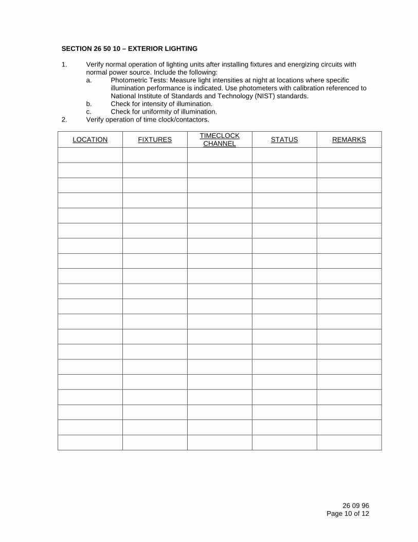
SECTION 26 50 10 – EXTERIOR LIGHTING 1. Verify normal operation of lighting units after installing fixtures and energizing circuits with
normal power source. Include the following: a. Photometric Tests: Measure light intensities at night at locations where specific
illumination performance is indicated. Use photometers with calibration referenced to National Institute of Standards and Technology (NIST) standards.
b. Check for intensity of illumination. c. Check for uniformity of illumination. 2. Verify operation of time clock/contactors.
LOCATION FIXTURES TIMECLOCK CHANNEL
STATUS REMARKS

26 09 96
Page 11 of 12
SECTION 26 72 00 – FIRE ALARM SYSTEM 1. Verify FACP operation. 2. Verify alarm horns/strobes. 3. Verify HVAC shutdown.
LOCATION DEVICE OPERATIONAL STATUS REMARKS
26 09 96
Page 12 of 12
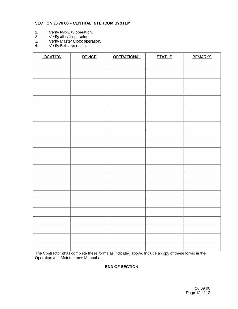
SECTION 26 76 80 – CENTRAL INTERCOM SYSTEM 1. Verify two-way operation. 2. Verify all-call operation. 3. Verify Master Clock operation. 4. Verify Bells operation.
LOCATION DEVICE OPERATIONAL STATUS REMARKS
The Contractor shall complete these forms as indicated above. Include a copy of these forms in the Operation and Maintenance Manuals.
END OF SECTION
Soils for Earthwork 31 05 13.01 - 1 O.N. Stevens WTP Maintenance Building – E16427 JFD – 11/13/02
31 05 13.01 SOILS FOR EARTHWORK
1.00 GENERAL
1.01 WORK INCLUDED
A. This section of the specifications describes the various classes of Earth Fill. All of the classes of Earth Fill contained in this specification may not be used on this project. The classes of Earth Fill used on this project are shown on the drawings or specified in other sections of the specifications. This specification section does not include specifications for placement and compaction of Earth Fill. Specifications for placement and compaction of Earth Fill are included in other sections of the specifications and/or shown on the drawings.
1.02 STANDARDS
A. Soil materials shall be classified into the appropriate class of Earth Fill shown below according to ASTM D2487 “Standard Classification of Soils for Engineering Purposes (Unified Soil Classification System)” or other appropriate methods as designated by the Engineer.
2.00 PRODUCTS
2.01 MATERIALS; CLASSIFICATIONS
A. Class 1 Earth Fill: Limited to clays and sandy clays classified as CH material with a liquid limit greater than or equal to 50, a plasticity index greater than or equal to 25, and a minimum of 60 percent passing the No. 200 sieve, which are free of organic materials.
B. Class 2 Earth Fill: Limited to clays and sandy clays classified as CH and CL materials with a coefficient of permeability less than or equal to 1.0 x 10⁻⁷ cm/sec, a liquid limit greater than or equal to 30, a plasticity index greater than or equal to 15, and more than 50 percent passing the No. 200 sieve, which are free of organic materials.
C. Class 3 Earth Fill: Consist of any materials classified as CH, CL, SM, SP, SP-SM, SC, and GC, which have a minimum plasticity index of 4, which are free of organic materials.
D. Class 4 Earth Fill: Consist of materials which are classified as SP, SM, SC, CL, or dual classifications thereof, which have a liquid limit less than or equal to 35 and a plasticity index of a minimum of 4 and a maximum of 15, which are free of organic materials.
E. Class 5 Earth Fill: Consist of materials classified as SP or SP-SM which have a plasticity index less than or equal to 4 and a maximum of 12 percent passing the No. 200 sieve, which are free of organic materials.
F. Class 12 Earth Fill: Consist of soils suitable for topsoil which are relatively free of stones or other objectionable debris, which have sufficient humus content to readily support vegetative growth. The suitability of soils for topsoil shall be subject to the approval of the Engineer.
3.00 EXECUTION (NOT APPLICABLE)
END OF SECTION

31 31 16Page 1 of 2
8/3/2017
SECTION 31 31 16TERMITE CONTROL
PART 1 GENERAL1.01 SECTION INCLUDES
A. Chemical soil treatment.1.02 REFERENCE STANDARDS
A. Title 7, United States Code, 136 through 136y - Federal Insecticide, Fungicide and RodenticideAct; United States Code; 1947 (Revised 2001).
1.03 SUBMITTALSA. See Section 01 33 02 for submittal procedures.B. Product Data: Indicate toxicants to be used, composition by percentage, dilution schedule,
intended application rate.C. Test Reports: Indicate regulatory agency approval reports when required.D. Manufacturer's Application Instructions: Indicate caution requirements.E. Manufacturer's Certificate: Certify that toxicants meet or exceed specified requirements.F. Certificate of compliance from authority having jurisdiction indicating approval of toxicants.G. Record date and rate of application.H. Maintenance Data: Indicate re-treatment schedule.I. Warranty: Submit warranty and ensure that forms have been completed in Owner's name.
1.04 QUALITY ASSURANCEA. Installer Qualifications: Company specializing in performing this type of work.
1. Having minimum of 5 years documented experience.2. Approved by manufacturer of treatment materials.3. Licensed in Texas.
1.05 WARRANTYA. See Section 01 33 03 for additional warranty requirements.B. Provide five year installer's warranty against damage to building caused by termites.
1. Include coverage for repairs to building and to contents damaged due to building damage.Repair damage and, if required, re-treat.
PART 2 PRODUCTS2.01 MATERIALS
A. Manufacturers:1. Bayer Environmental Science Corp: www.backedbybayer.com/pest-management.2. FMC Professional Solutions: www.fmcprosolutions.com.3. Syngenta Professional Products: www.syngentaprofessionalproducts.com.4. Substitutions: See Section 01 31 14 - Product Requirements.
B. Toxicant Chemical: EPA approved; synthetically color dyed to permit visual identification oftreated soil.
C. Diluent: Recommended by toxicant manufacturer.2.02 MIXES
A. Mix toxicant to manufacturer's instructions.
31 31 16Page 2 of 2
8/3/2017
PART 3 EXECUTION3.01 EXAMINATION
A. Verify that soil surfaces are unfrozen, sufficiently dry to absorb toxicant, and ready to receivetreatment.
B. Verify final grading is complete.3.02 APPLICATION
A. Comply with requirements of U.S. EPA and applicable state and local codes.B. Spray apply toxicant in accordance with manufacturer's instructions.C. Apply Toxicant at Following Locations:
1. Under slabs-on-grade.2. At both sides of foundation surface.3. Soil within 10 feet of building perimeter.
D. Under slabs, apply toxicant immediately prior to installation of vapor barrier.E. Apply extra treatment to structure penetration surfaces such as pipe or ducts, and soil
penetrations such as grounding rods or posts.F. Re-treat disturbed treated soil with same toxicant as original treatment.G. If inspection or testing identifies the presence of termites, re-treat soil and re-test.
3.03 PROTECTIONA. Do not permit soil grading over treated work.
END OF SECTION
Bridge Cranes 41 22 13.13 - 1 O.N. Stevens WTP Maintenance Facility – E16427
41 22 13.13 BRIDGE CRANES
1.00 GENERAL
1.01 WORK INCLUDED
A. Furnish labor, materials, equipment and incidentals necessary to install bridge crane and hoist assembly in the maintenance building as indicated on the plans.
1.02 QUALITY ASSURANCE
A. Acceptable Manufacturers:
1. Anchor Crane and Hoist Service Company of Dallas, Texas.
2. Gaffey, Inc., Fort Worth, Texas.
3. Approved Equal.
B. Design Criteria:
1. Crane design, including stress limitations, factors of safety, bearing life and contactor rating, shall be in accordance with applicable provisions of CMAA specifications, Class C (moderate service).
2. Equipment shall be in accordance with all safety features required by OSHA standards.
3. Components of each top running bridge crane shall be designed for the capacity indicated herein. Crane rail length, hook and trolley travel limits shall be as indicated on the plans and specified herein.
C. Factory Test: Equipment shall be fully assembled, subjected to no-load running tests and dismantled only as required to facilitate shipment.
D. Manufacturer’s Representative for Startup and Testing: The services of the Manufacturer’s technical representative shall be provided for pre-startup installation checks, startup assistance, training of Owner’s operating personnel, troubleshooting and other services as required in Section 01 75 00 “Starting and Adjusting.”
1.03 SUBMITTALS
A. Submittals shall be in accordance with Section 01 33 00 “Document Management” and shall include:
1. Shop Drawings.
a. Product data sheets
b. Project specific electrical equipment wiring diagrams
c. Data sheets for miscellaneous equipment (disconnect, cable, pushbutton station, etc.). Data sheets shall clearly indicate the model number being provided
Bridge Cranes 41 22 13.13 - 2 O.N. Stevens WTP Maintenance Facility – E16427
2. Operation and Maintenance Manuals.
a. Operation and maintenance manuals shall be prepared by the equipment manufacturer and shall contain the final certified shop drawings, submittals, list of manufacturer recommended spare parts, schematics, and maintenance procedures. O&M manuals shall include all field changes made during startup and testing.
b. Manuals may be manufacturer's standard instructions, but shall be supplemented as necessary to cover any special feature not included in standard material.
c. Operation and maintenance manuals shall include warranty information as well as a warranty information page that shall include information on the warranty start and end date as well as contact information for service.
1.04 STANDARDS
A. The applicable provisions of the following standards shall apply as if written here in their entirety:
AGMA American Gear Manufacturer’s Association
ANSI B30.16 Safety Code for Overhead Hoists
ANSI B30.2 American National Standards Institute – Cranes
ASTM American Society of Testing and Materials
AWS American Welding Society
CMAA Spec. #70 Crane Manufacturer’s Association of America
NEC National Electrical Code
NEMA National Electrical Manufacturers Association
OSHA Section 1910.179 Overhead and Gantry Cranes
2.00 PRODUCTS
2.01 BRIDGE
A. The crane bridge shall consist of double girders carried by the end truck. The girder construction shall either be rolled structural shapes, full reinforced, or fabricated box type sections with full depth and short diaphragms provided to maintain girder stiffness.
B. The girders shall be designed for moderate duty crane service (Class C) in accordance with CMAA Specification #70, revised 1983. The chemical and physical properties of the girders shall conform to ASTM A36 specifications.
C. The girders shall be notched at each end and seat angles shall be welded to the girders to provide a connection to the end trucks at the top, side and bottom by means of fit bolts. Heavy gusset plates shall be attached to the bottom of the truck to ensure rigidity and squareness. ASCE standard rails of proper size shall be secured to the girder by rail clips.
Bridge Cranes 41 22 13.13 - 3 O.N. Stevens WTP Maintenance Facility – E16427
2.02 END TRUCKS
A. The end trucks shall be built up from structural shapes and plates welded to form a rigid section with openings at each end to receive the truck wheels. The trucks shall be precision bored or otherwise assembled to provide perfect alignment of wheel bearing assemblies. The wheels shall be centrally located in each truck to distribute equal loading to each truck side.
B. Bumpers shall be installed at each end of the end trucks. These bumpers shall operate against the runway stops which shall be furnished with the crane. Rail sweeps shall be provided in front of bridge wheels.
2.03 WHEELS AND AXLES
A. Bridge wheels shall be forged and flame hardened or rim-toughened steel and shall be machined in a flat or tapered tread design to an accuracy meeting CMAA requirements.
B. Bridge drive may either be rotating or fixed axle type. Heat treated steel axles or pinions shall be supported on each side of the truck frame in anti-friction bearings. Truck reductions within reach of personnel are to be guarded.
C. Gears shall be of the helical, spur, or herringbone type, made from rolled or cast steel, with machine cut teeth. Horsepower ratings shall be in accordance with AGMA Standards, as described in CMAA Specifications.
D. Bearings shall be combined radial and thrust type, double-row, spherical ball bearings, either pre-lubricated and sealed, or fitted for pressure lubrication. Pressure lubrication fittings shall be located in accessible locations for ease of maintenance.
E. Bridge brakes shall be electrically operated, adjustable, suitable for the service class indicated, and shall have rated torque capacities as specified in CMAA Specifications.
2.04 TROLLEY SPECIFICATIONS
A. The trolley frame shall be a fabricated steel weldment composed of structural shapes and plates and sized to adequately support the hoist machinery. Wheel support points shall be reinforced and accurately machined to ensure correct wheel alignment.
B. Trolley drive may either be rotating or fixed axle type. Heat treated steel axles or pinions shall be supported on each side of the truck frame in anti-friction bearings. Truck reductions within reach of personnel are to be guarded.
C. Single girder trolley units shall have a stabilizing tiller assembly provided to prevent tipping during load pickup.
D. Wheels shall be rolled or forged steel with treads and flanges heat- treated, or cast iron wheels with chilled tread. Wheels shall have a minimum tread hardness of 425 Brinell. Clearances, wheel loads, and the Manufacturer’s tolerances shall be in accordance with CMAA Specifications.
E. Wheel axles shall be made of alloy steel, accurately machined and ground to receive inner bearing races. When rotating axles are used, wheels shall be mounted on axles with a press fit and keys, or with keys alone.
Bridge Cranes 41 22 13.13 - 4 O.N. Stevens WTP Maintenance Facility – E16427
F. Gears shall be of the helical, spur, or herringbone type, made from rolled or cast steel, with machine cut teeth. Horsepower ratings shall be in accordance with AGMA Standards, as described in CMAA Specifications.
G. Bearings shall be combination radial and thrust type, double-row, angular contact ball bearings, or single-row tapered roller bearings, either pre-lubricated and sealed, or fitted for pressure lubrication. Pressure lubrication fittings shall be located in accessible locations for ease of maintenance.
H. Provide a short grab rail around the perimeter of the trolley that is no higher than the highest point on the trolley.
2.05 HOIST
A. Hoists shall be electric, wire rope type, as specified herein.
B. The hoisting machinery shall consist of a rope drum, driven through suitable gear reductions by an electric motor operator, load blocks, hooks, hoisting rope, sheaves, and hoist braking.
C. Hoist gearing shall be enclosed in an oil tight gear case. Bearings and gears shall be splash lubricated and bearings selected to provide a B-10 life to equal or exceed CMAA requirements. Gear case shall be provided with a bolt-on cover for full access to bearings and gearing. An inspection cover shall be provided to permit gear inspection without draining oil. The gear case shall be equipped with an oil level sight gauge.
D. Hoist gearing shall be helical or spur type made from rolled or cast steel and shall have machine cut teeth. Pinions shall be made from alloy steel and shall be heat-treated.
E. The hoist drum shall be fabricated from seamless steel, tubing grooved to take the full length of each cable in one layer. At least two wraps of rope shall remain on the drum when the bottom block is in the lowest position. Drum shall be grooved on the left and right side to provide true vertical lift.
F. The diameter of the rope drums shall not be less than 24 times the diameter of the hoisting cable which shall be extra flexible improved plow steel having six strands of 37 wires per strand.
G. The load block shall be furnished with ball or roller bearing sheaves and a roller type hook thrust bearing. Hook block sheaves and running sheaves shall be rolled or forged steel, furnished with anti-friction type bearings. Pitch diameter of the running sheaves to be minimum 24 times the rope diameter.
H. Hooks shall have sufficient ductility to open noticeably before hook failure as a result of abuse or overload. The load hook shall be equipped with safety latch and shall be free to rotate 360 degrees with rated load, and shall be positively held in place with locknuts, collars, or other suitable devices.
I. A heavy duty three pole fused safety type disconnect switch shall be provided on the bridge adjacent to the runway power pick up. The disconnect switch shall be in a NEMA 4X, 304 stainless steel enclosure. In addition, a mainline contactor shall be furnished which will cut all power circuits to the crane. The contactor is to be operable from the pendant. The mainline contactor shall also provide low voltage protection for the crane.
Bridge Cranes 41 22 13.13 - 5 O.N. Stevens WTP Maintenance Facility – E16427
J. Bridge, trolley, and hoist motions shall be controlled from a pushbutton station festooned and suspended from a track running the full length of the bridge permitting operation from any point along the span independent of trolley location. Flat multi-conductor cables shall be suspended from ball bearing trolleys with swiveling hangers and support brackets to prevent sharp bends.
K. Controls shall be mounted in NEMA 4X, steel enclosures. Control apparatus shall be logically arranged and wired in a neat, workmanlike manner, secured and properly tagged at each end. Fully marked terminal strips shall be provided at the bottom of each panel for connection of all external wiring.
L. Crane motors shall be of a type specifically designed for crane and hoist duty. Bearings shall be of the pre-lubricated anti-friction type and sealed. Primary motor voltage shall be 460V, 3-phase, 60Hz. Motors shall be rated 30 minute duty.
M. On cranes which must be disassembled for shipment, conduit runs shall be furnished and made up, wires cut to proper length and tagged. Junction boxes shall be provided at all places where electrical reconnections must be made in the field.
N. A control circuit, upper limit switch shall be provided.
2.06 BRAKES
A. The hoist shall have a dual braking system consisting of an electric heavy duty shoe or disc brake and a mechanical load brake, either capable of holding the load when power to the hoist motor is off.
B. The bridge and trolley shall be provided with a shoe or disc brake with a 75 percent torque rating on the bridge and a 50 percent torque rating on the trolley. The brake shall be provided with a means for adjustment in the field. Brakes shall allow quick stopping so that the bridge and trolley do not coast.
2.07 ELECTRICAL EQUIPMENT
A. The Crane Manufacturer shall furnish and assemble electrical equipment on the crane, including motors, motor starters, pendant control and conduit. Bridge conductors may be removed for shipment. Wire on the crane shall be furnished by the Crane Manufacturer, cut to length and installed, as far as practical, for shipment.
B. The bridge crane shall be a maximum of 60 amps at 460 Volt, 3-phase, 60 Hertz. If a larger ampacity bridge crane is provided as an alternate, the Contractor shall be responsible for all modifications required to the electrical system, including disconnects, feeders to the equipment, feeders from the switchboard, circuit breaker at the switchboard, etc. at no cost to the Owner. Power for the bridge crane shall be 460 Volt, 3-phase, 60 Hertz supplied from a non-fused disconnect switch provided by the Contractor.
C. The electrical equipment shall be furnished in accordance with the applicable requirements of Article 610 of the latest issue of the National Electrical Code, and the installation and wiring shall be made in accordance with Section 26 05 00 “Common Work Results for Electrical.”
Bridge Cranes 41 22 13.13 - 6 O.N. Stevens WTP Maintenance Facility – E16427
D. Motors shall be squirrel-cage type and shall be built in accordance with NEMA Standards, rated on not less than a 30 minute basis, with temperature rise in accordance with the latest NEMA Standards for the class of insulation and enclosure used, and shall be provided with anti-friction bearings. Squirrel-cage motors shall be NEMA Design D, with high starting torque, low starting current and high slip at full load. Overload relays shall be provided in all phases of polyphase alternating current motors.
E. Bridge conductors shall be of the enclosed bus bar or festooned cable type as indicated herein, and trolley conductors shall be of festooned cable type, as hereinafter specified. The bridge and trolley conductor voltage drops from the runway supply taps shall permit the crane motors to operate within voltage tolerances of plus or minus 10 percent when building system is at ± 5 percent of design voltage.
F. Festooned flat cable conductors shall consist of flexible conductor cable, supported by a heavy-duty roller, permanently lubricated bearing, monorail system that will dispense and retrieve the flexible conductor cable during trolley travel without twisting or tangling. Provide 20 percent spare conductors in each cable assembly.
G. Grounding on the equipment and provisions for grounding the equipment to external grounding systems shall be in accordance with the requirements of the NEC and state and local regulations.
H. Electric cranes shall be equipped with a pendant control having momentary contact pushbuttons, and shall be provided with a device which will disconnect motors from the line on failure of power and will not permit any motor to be restarted until the controller handle is brought to the OFF position, or a reset switch or button is operated. Undervoltage protection shall be provided as a function of each motor controller, or by a magnetic main line contactor.
I. Controls shall be fully magnetic of the plain reversing type, housed in NEMA 4X, steel enclosure. Each magnetic control shall have contactors of sufficient size and quantity for starting, accelerating, reversing and stopping duty for the specified crane service class.
J. Provide control transformers to supply 120 volts AC to the pushbutton control stations. The pushbutton control stations shall be of heavy duty, oil-tight construction and suspended from the trolley or bridge. The control wire cable shall be attached to the enclosure support at not more than 6-foot intervals. The control station shall contain pushbuttons for control of the crane, hoist, and trolley and an ON/OFF switch to operate a main line contactor which shall remove all power from the control station.
2.08 CRANE INTERCONNECTION WIRING
A. The crane shall be wired in accordance with Article 610 of the latest issue of the National Electric Code. Wiring shall be enclosed in galvanized steel conduit or steel raceway. Power and control wiring shall be heat resistant type.
B. Bridge conductors shall be festooned type using top quality and properly sized flat multi-conductor cables specifically designed for this type service. Cables shall be supported from ball bearing trolleys by means of hangers and brackets which prevent sharp cable bends.