Embed Size (px)
Citation preview

Hartmann Controls Corp.Toll free 1-877-411-0101Phone: (705) 719-6705
Fax: (705) 792-5632www.hartmann-controls.com
Specifier Notes typically precede specification text; delete notes in final copy of specification. Trade/brand names with appropriate symbols typically are used in Specifier Notes; symbols are not usedin specification text. Metric conversion, where used, is soft metric conversion.
SECTION 28 13 00
ACCESS CONTROL
PART 1 GENERAL
1.1 SUMMARY
A. Section Includes: Server hardware and software, client software, security access devices, access control, relaycontrol, elevator control, credential creation and credential holder database and management, Digital Video Integration, Basic Burglary Alarm Integration
Specifier Note: Revise paragraph below to suit project requirements. Add section numbers and titles per CSI MasterFormat and specifier’s practice.
B. Related Sections:
1. Section [08 11 00 - Metal Doors and Frames] [_____].
2. Section [08 14 00 - Wood Doors] [_____].
3. Section [08 41 13 – Aluminum Framed Entrances and Store fronts] [_____]
4. Section [08 71 00 - Door Hardware] [_____].
5. Section [14 20 00 - Elevators] [_____].
6. Section [21 09 00 – Instrumentation and Control for Fire-Suppression Systems] [_____]
7. Section [25 15 00 - Integrated Automation Software] [_____].
8. Section [26 05 00 - Common Work Results for Electrical] [_____].
9. Section [26 05 19 - Low-Voltage Electrical Power Conductors and Cables] [_____].
10. Section [27 10 00 - Structured Cabling] [_____].
Specifier Note: Article below may be omitted when specifying manufacturer’s proprietary products and recommended installation. Retain Reference Article when specifying products and installation by an industry reference standard. If retained, list standard(s) referenced in this section. Indicate issuing authority name, acronym, standard designation and title. Establish policy for indicating edition date of standard referenced. Conditions of the Contract or Section 01 42 19 - Reference Standards may establish the edition date of standards. This article does not require compliance with standard, but is merely a listing of references used. Article below should list only those industry standards referenced in this section.Retain only those reference standards to be used within the text of this Section. Add and delete as required for specific project.
1.2 REFERENCES
A. Institute of Electrical and Electronics Engineers (IEEE):
11. IEEE 1100 Recommended Practice for Powering and Grounding Electronic Equipment.
B. National Fire Protection Association (NFPA):
12. NFPA 70 2005 National Electrical Code.
13. NFPA 72 National Fire Alarm Code.
14. NFPA 80 Fire Doors and Windows, 2007 Edition.
15. NFPA 101 Life Safety Code, 2009 Edition.
1

C. International Organization for Standardization (ISO):
16. ISO 7816 Smart Card Standard.
2

Specifier Note: Article below should be restricted to statements describing design or performance requirements and functional (not dimensional) tolerances of a complete system. Limit descriptions to composite and operational properties required to link components of a system together and to interface with other systems.
1.3 SYSTEM DESCRIPTION
A. Design Requirements: Provide products and systems that have been manufactured, fabricated and installed to the following criteria:
17. Comply with IEEE 1100.
18. Comply with NFPA 70.
19. Comply with NFPA 72.
20. Comply with NFPA 80.
21. Comply with NFPA 101.
22. Access Control Management System: Protector.Net Electronic Access Control System.
a. System Capabilities:
1) Fully distributed processing, field devices not dependent on on server operations once programmed.
2) Control access to unlimited doors.
3) Control elevator access up to 64 floors per Cab.
4) Manage and control access for up to 50,000-100,000 credentials per controller.
5) Unlimited remote sites.
6) Configurable alert screen and email notifications
7) Photo ID badging integration via SQL database
8) Readers, inputs and outputs expandable and/or modifiable.
9) Single software program controlled.
10) 50 Programmable Holidays per Holiday Group
11) 50 Holiday Groups configurable
12) Multi-site Management via Partitions
13) No client software needed, client accesses via HTML5 browser
14) Local anti-passback
15) Full integration and customization of all system components.
16) Online reconfiguration through system programming without hardware changes.
b. Access Control Functions:
17) Validation of Credential based on Time of day, Day of week, Holiday scheduling, mode of Door, and special event schedules.
18) Simultaneous controlled access with various reader technologies;
a) Proximity
b) Pin number
c) Biometrics
d) Mag stripe
e) Bar code
19) Automatic or manual retrieval of cardholder photographs.
20) First person in capability.
21) Access validation based on positive verification of Credential, PIN, or Credential/PIN combination, or dual credential with one credential being a supervisor credential.
22) Differentiates between valid credential presentation only, and valid credential presentation followed by entry (when using door position switch).
3

c. Passwords:
23) Assignable.
24) Unlimited number of system Administrators.
25) Permissions of system Administrators are definable per Administrator.
26) Administrator actions/capabilities range from basic system monitoring to control of all system functions.
27) Administrators can be linked and managed by LDAP systems.
d. System Programming:
28) User-friendly, intuitive, and responsive HTML5 web client interface.
29) Single Page Application (SPA) architecture allows seamless browser transition between pages.
30) Ability to import large quantities of cards in a CSV file format.
e. Alert messages:
31) Ability to monitor for specific event types, run reports based on specific event types orevents associated with devices or users.
32) Alert information displayed in text format on the notifications area, and highlighted based on severity of alert.
33) Video feed switching capabilities associated with alert via IP communication. (fully configurable)
34) Capability of E-Mailing alert events to administrators.
f. System integration:
1) ViconNet® Digital Video Management system integration
2) CardPresso® Photo badging software integration.
3) Alarm system integration via configurable dry contact output/input.
4) ASSA ABLOY Aperio® hub integration
B. System minimum Requirements:
Specifier Note: The computer specifications are the minimum standards for a basic system. When a system includes a large number of clients, controllers, and/or users, additional server power is strongly recommended. Central Processing Unit Computer:
23. Microsoft compatible Windows 7 or newer.
24. 2Ghz or faster 32-bit (x86) or 64-bit (x64) processor. Two or more cores.
25. 4GB RAM for 32-bit and 4GB RAM for 64-bit
26. DVI or HDMI monitor
27. 1GB hard drive space required (Additional space required for database).
28. Microsoft .Net Framework 4.5 Full.
29. Microsoft SQL Server 2008 or SQL Server 2008 Express or Higher.
4

Specifier Note: Article below includes submittal of relevant data to be furnished by Contractor before, during or after construction. Coordinate this article with Architect’s and Contractor’s duties and responsibilities in Conditions of the Contract and Section 01 33 00 - Submittal Procedures.
1.4 SUBMITTALS
A. General: Submit listed submittals in accordance with Conditions of the Contract and Section [01 33 00 - Submittal Procedures] [_____].
B. Product Data: Submit product data for specified products, ____ copies
C. Manufacturer’s Instructions: Manufacturer’s Technical installation guide, and Manufacturer’s Software Guide, ____copies.
D. Drawings: Submit shop drawings detailing installation procedures, including layout, dimensions and support placement, ___ copies.
Specifier Note: Coordinate paragraph below with Part 3 Field Quality Requirements Article. Retain or delete as applicable.
E. Closeout Submittals: Submit the following:
30. Warranty: Warranty documents.
31. Operation and Maintenance Data: Operation and maintenance data for installed products in accordance with Section [01 78 00 - Closeout Submittals] [_____]. Include methods for maintaining installed products and precautions against cleaning materials and methods detrimental to finishes and performance.
1.5 QUALITY ASSURANCE
A. Qualifications:
32. Installer: Experienced in performing work of this section, and having specialized knowledge in installationof systems similar to that required for this project. Installer must be a manufacturer trained and authorized Protector.Net installer, providing termination, commissioning and end-user training(technical and/or administrative) services as required.
33. Manufacturer: Capable of providing field service representation during construction, and approving installation and application method, as well as providing termination, commissioning and end user training (technical and/or administrative) services as required.
Specifier Note: Paragraph below should list obligations for compliance with specific code requirements particular to this section. General statements to comply with a particular code are typically addressed in Conditions of the Contract and Section 01 41 00 - Regulatory Requirements. Repetitive statements should be avoided.
B. Regulatory Requirements: In accordance with Section [01 41 00 - Regulatory Requirements] [_____].
34. IEEE 1100.
35. NFPA 70.
36. NFPA 72.
37. NFPA 80.
38. NFPA 101.
C. Pre-installation Meetings: Conduct pre-installation meeting to verify project requirements, manufacturer’s installation instructions and manufacturer’s warranty requirements. Comply with [Section 01 31 19 - Project Meetings].
1.6 DELIVERY, STORAGE & HANDLING
A. General: Comply with Section [01 61 00 - Common Product Requirements].
B. Ordering: Comply with manufacturer’s ordering instructions and lead time requirements to avoid construction delays.
C. Delivery: Deliver materials in manufacturer’s original, unopened, undamaged containers with identification labels intact.
D. Storage and Protection: Store materials indoors, protected from exposure to harmful weather conditions and at a temperature between 10 and 30 degrees Celsius, and between 10% and 90% relative humidity, non-
5

condensing. Product boxes not to be stacked more than 3 high, and are not to have anything stacked on top or directly beside the product that could possibly cause damage based on weight, moisture, corrosive content etc.
Specifier Note: Coordinate article below with Conditions of the Contract and with Division 01 Closeout Submittals (Warranty) Section.
1.7 WARRANTY
A. Project Warranty: Refer to Conditions of the Contract for project warranty provisions. Submit, for Owner’s acceptance, manufacturer’s standard warranty document executed by authorized company official. Manufacturer’s warranty is in addition to, and not a limitation of, other rights Owner may have under Contract Documents.
B. Manufacturer’s Warranty: Hartmann Controls warrants all Protector.Net Controllers manufactured by Hartmann are free from defects in material and workmanship. However this warranty does not cover non-manufactured peripheral products sold by Hartmann. Peripheral products are covered by the manufacturer’s warranty of the particular peripheral device.
C. Warranty Period: Hartmann Controls Protector.Net Controllers carry a 2 (two) year warranty from date of substantial completion. Hartmann Controls Corp will repair or replace defective equipment upon return to its facility, if they find that the warranty was breached in any way, Hartmann Controls Corp will not warrant any damage that occurred during shipping or handling, or damage caused by a repair or an attempt to repair by any person other than those authorized by Hartmann Controls. This warranty covers normal industrial use and does not cover defects or damage to any product which, in the sole opinion of Hartmann Controls Corp has been subject to improper installation, unauthorized modification, misuse, neglect, abuse, or abnormal operating conditions, improper storage, or which has been attributable to acts of God such as lighting. Installation, which is not in accordance with the installation instructions, published by Hartmann Controls, will void the warranty. This warranty does not cover defects or damage caused by a product, which is not approved by Hartmann Controls Corp and is connected to a Protector.Net system.
The said warranty only applies to the original purchaser and is and shall be in lieu of any and all other warranties. ** Please note this does not include shipping, which will be supplied by the customer.
6

PART 2 PRODUCTS
Specifier Note: Retain article below for proprietary method specification. Add product attributes performance characteristics, material standards and descriptions as applicable. Use of such phrases as “or equal” or “or approved equal” or similar phrases may cause ambiguity in specifications. Such phrases require verification (procedural, legal and regulatory) and assignment of responsibility for determining “or equal” products.
2.1 ELECTRONIC ACCESS CONTROL MANAGEMENT SYSTEM
A. Manufacturer: HARTMANN CONTROLS CORPORATION
1. Contact: PHONE 877-411-0101, FAX 705-792-5632. www.hartmann-controls.com
B. System Components:
1. 1 Door Controller: ODM-M
a. Supports up to 2 readers (IN and OUT configuration)
b. Power input: IEEE 802.3af PoE standard provides up to 15.4 Watts.
c. Processor: 32-Bit Microprocessor-Based
d. Operation mode:
1) Requires server software for credential/schedule configuration.
2) Will operate stand alone once programmed.
e. Storage:
1) Up to 100,000 users/cardholders per controller.
2) 50,000 event storage onboard
f. Terminals: Quick disconnect terminal headers.
g. Reader Communications:
1) 2 x Wiegand Data1/Data0, with optional LED and buzzer control.
2) LED Indicator: 2 x Reader active indicators.
h. Lock Power:
1) Solid State Wet Relay 12VDC @ 500mA / 24VDC @ 250 mA (with opt. Converter).
2) LED Indicator:1 X Lock Power LED
i. Relay Outputs:
1) 2 X Solid State Relay 60V (TVS circuit limits 24V), 500mA.
2) Fully configurable, no mechanical parts.
3) Dry Contact.
4) LED Indicator: 2 x output indicator.
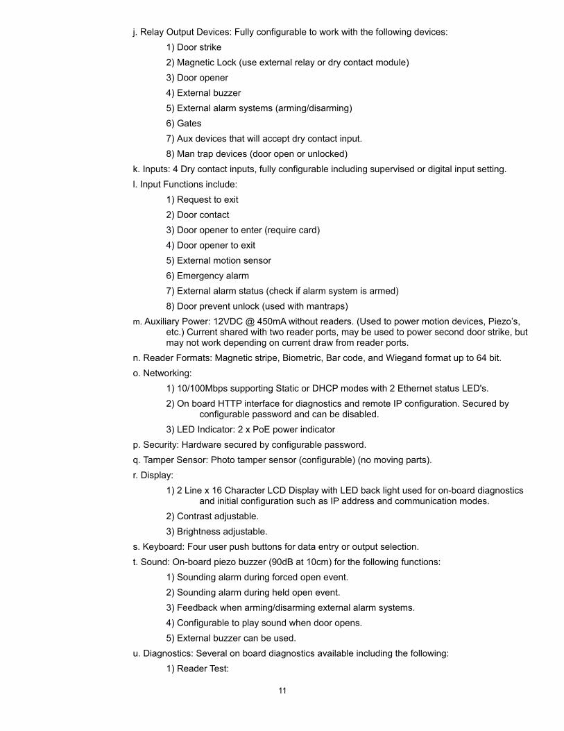
j. Relay Output Devices: Fully configurable to work with the following devices:
1) Door strike
2) Magnetic Lock (use external relay or dry contact module)
3) Door opener
4) External buzzer
5) External alarm systems (arming/disarming)
6) Gates
7) Aux devices that will accept dry contact input.
8) Man trap devices (door open or unlocked)
k. Inputs: 4 Dry contact inputs, fully configurable including supervised or digital input setting.
7

l. Input Functions include:
1) Request to exit
2) Door contact
3) Door opener to enter (require card)
4) Door opener to exit
5) External motion sensor
6) Emergency alarm
7) External alarm status (check if alarm system is armed)
8) Door prevent unlock (used with mantraps)
9) Aux input:
a) Pulse selected output
b) Activate selected output
c) Deactivate selected output
d) Toggle selected output
e) Activate alarm interfaced
f) Disengage emergency alarm
g) Override doors with crisis levels
m. Auxiliary Power: 12VDC @ 450mA without readers. (Used to power motion devices, Piezo’s, etc.) Current shared with two reader ports.
n. Reader power: 12VDC @ 450mA max shared across both reader port and Auxiliary 12VDC output.
o. Reader Formats: Magnetic stripe, Biometric, Bar code, and Wiegand format up to 64 bit.
p. Networking:
1) 10/100Mbps supporting Static or DHCP modes with 2 Ethernet status LED's.
2) On board HTTP interface for diagnostics and remote IP configuration. Secured by configurable password and can be disabled.
3) LED Indicator: 2 x PoE power indicator
q. Security: Hardware secured by configurable password.
r. Tamper Sensor: Photo tamper sensor (configurable) (no moving parts).
s. Display:
1) 2 Line x 16 Character LCD Display with LED back light used for on-board diagnostics and initial configuration such as IP address and communication modes.
2) Contrast adjustable.
3) Brightness adjustable.
t. Keyboard: Four user push buttons for data entry or output selection.
u. Diagnostics: Several on board diagnostics available including the following:
1) Reader Test:
a) Ability to test if the reader on port 1 or 2 is able to read a card, and shows bitformat, facility code and card number on LCD display.
2) Output Test:
a) Ability to manually trigger each of the 3 solid state relays, used to test that output devices such as door strikes are wired up correctly.
3) Input Test:
a) Ability to test each dry contact input for changes.
8

b) Indicator and audible alert if an input state changes.
c) Used to test input devices such as door contacts, REX, and auto opener buttons are wired correctly.
4) Ping with IP:
a) Ability to perform a basic network connectivity test by communicating with the server IP via ICMP protocol.
5) Ping with Name:
a) Ability to perform a basic network connectivity test by communicating to the server by resolving the name of the server via a Dynamic Name Service(DNS).
6) Debug mode:
a) Optional debug mode that allows extra logging of communications and panel decisions.
7) Read Only mode: Displays controller configuration and miscellaneous information
a) Panel Name
b) Area name (anti-passback)
c) Panel ID
d) IP Address
e) Panel MAC Address
f) Panel Subnet Mask
g) Panel Gateway
h) Panel DNS
i) Communication mode
j) Server IP Address/Name
k) Server Port
l) Firmware Version
m) Network Name
n) Door State
o) Door Mode
p) DHCP Bound address
q) Time (UTC and Local)
r) Connection Status
v. On-board Communication Configuration:
1) Ability to configure communication method to server (name or IP address).
2) Ability to configure name or IP address that the server can be reached.
3) Ability to configure network settings of controller, including:
a) Static IP address or DHCP
b) Controller IP Address, subnet mask, default gateway, DNS server.
w. Sound: On-board piezo buzzer (90dB at 10cm) for the following functions:
1) Sounding alarm during forced open event.
2) Sounding alarm during held open event.
3) Feedback when arming/disarming external alarm systems.
4) Configurable to play sound when door opens.
9

5) External buzzer can be used.
x. Motion PIR(optional):
1) PIR motion sensor mounted on bottom of unit for authorizing exit without card read.
2) Configurable to unlock the door upon motion detection.
3) Sensitivity fully configurable via software.
y. Time: Keeps up to 1 month without power connection, No battery needed. Automatic DST switch.
z. Firmware: Controller firmware is remotely upgradable from server software for added functionality, features and patches.
aa. Anti-passback: Local anti-passback, independent of software.
bb. Labels: Controller inputs/outputs are physically labeled with default usages, buttons and panelmodel are also labeled.
cc. Operating Temperature: 0 degrees Celsius to 50 degrees Celsius.
dd. Operating Humidity: 10% to 90% relative humidity, non-condensing.
ee. Expandable modular design.
ff. PCB Dimensions: 19.6 cm (W) X 7.4cm (H) (7.716” X 2.913”).
gg. Enclosure Dimensions: 29.9 cm (W) X 8.8 cm (H) X 5.93 cm (D) (11.7”X3.46”X2.33”).
hh. Enclosure Color: Black or White.
2. 2 Door Controller: POE-TDM
a. Supports 2 readers (1 for each door).
b. Power input: IEEE 802.3af PoE standard provides up to 15.4 Watts.
c. Processor: 32-Bit Microprocessor-Based.
d. Storage:
1) Up to 100,000 users/cardholders per controller.
2) 50,000 event storage onboard.
e. Terminals: Quick disconnect terminal headers.
f. Reader Communications:
1) 2 x Wiegand Data1/Data0, with optional LED and buzzer control.
2) LED Indicator: 2 x Reader active indicators.
g. Lock Power 1:
1) Solid State Wet Relay 12VDC @ 500mA / 24VDC @ 250 mA (with opt. Converter).
2) LED Indicator:1 X Lock Power LED.
h. Lock Power 2:
1) Solid State Relay 60V (TVS circuit limits 24V), 500mA, fully configurable, no mechanical parts. Requires external lock power for second strike or draw power from Auxiliary Power.
2) Dry contact.
3) LED Indicator: 1 x output indicator.
i. Relay Outputs:
1) 1 X Solid State Relay 60V (TVS circuit limits 24V), 500mA.
2) Fully configurable, no mechanical parts.
3) Dry Contact.
4) LED Indicator: 1 x output indicator.
10
j. Relay Output Devices: Fully configurable to work with the following devices:
1) Door strike
2) Magnetic Lock (use external relay or dry contact module)
3) Door opener
4) External buzzer
5) External alarm systems (arming/disarming)
6) Gates
7) Aux devices that will accept dry contact input.
8) Man trap devices (door open or unlocked)
k. Inputs: 4 Dry contact inputs, fully configurable including supervised or digital input setting.
l. Input Functions include:
1) Request to exit
2) Door contact
3) Door opener to enter (require card)
4) Door opener to exit
5) External motion sensor
6) Emergency alarm
7) External alarm status (check if alarm system is armed)
8) Door prevent unlock (used with mantraps)
m. Auxiliary Power: 12VDC @ 450mA without readers. (Used to power motion devices, Piezo’s, etc.) Current shared with two reader ports, may be used to power second door strike, but may not work depending on current draw from reader ports.
n. Reader Formats: Magnetic stripe, Biometric, Bar code, and Wiegand format up to 64 bit.
o. Networking:
1) 10/100Mbps supporting Static or DHCP modes with 2 Ethernet status LED's.
2) On board HTTP interface for diagnostics and remote IP configuration. Secured by configurable password and can be disabled.
3) LED Indicator: 2 x PoE power indicator
p. Security: Hardware secured by configurable password.
q. Tamper Sensor: Photo tamper sensor (configurable) (no moving parts).
r. Display:
1) 2 Line x 16 Character LCD Display with LED back light used for on-board diagnostics and initial configuration such as IP address and communication modes.
2) Contrast adjustable.
3) Brightness adjustable.
s. Keyboard: Four user push buttons for data entry or output selection.
t. Sound: On-board piezo buzzer (90dB at 10cm) for the following functions:
1) Sounding alarm during forced open event.
2) Sounding alarm during held open event.
3) Feedback when arming/disarming external alarm systems.
4) Configurable to play sound when door opens.
5) External buzzer can be used.
u. Diagnostics: Several on board diagnostics available including the following:
1) Reader Test:
11

a) Ability to test if the reader on port 1 or 2 is able to read a card, and shows bitformat, facility code and card number on LCD display.
2) Output Test:
a) Ability to manually trigger each of the 3 solid state relays, used to test that output devices such as door strikes are wired up correctly.
3) Input Test:
a) Ability to test each dry contact input for changes.
b) Indicator and audible alert if an input state changes.
c) Used to test input devices such as door contacts, REX, and auto opener buttons are wired correctly.
4) Ping with IP:
a) Ability to perform a basic network connectivity test by communicating with the server IP via ICMP protocol.
5) Ping with Name:
a) Ability to perform a basic network connectivity test by communicating to the server by resolving the name of the server via a Dynamic Name Service(DNS).
6) Debug mode:
a) Optional debug mode that allows extra logging of communications and panel decisions.
7) Read Only mode: Displays controller configuration and miscellaneous information
a) Panel Name
b) Area name (anti-passback)
c) Panel ID
d) IP Address
e) Panel MAC Address
f) Panel Subnet Mask
g) Panel Gateway
h) Panel DNS
i) Communication mode
j) Server IP Address/Name
k) Server Port
l) Firmware Version
m) Network Name
n) Door State
o) Door Mode
p) DHCP Bound address
q) Time (UTC and Local)
r) Connection Status
v. On-board Communication Configuration:
1) Ability to configure communication method to server (name or IP address).
2) Ability to configure name or IP address that the server can be reached.
3) Ability to configure network settings of controller, including:
a) Static IP address or DHCP
b) Controller IP Address, subnet mask, default gateway, DNS server.
12

w. Motion PIR(optional):
1) PIR motion sensor mounted on bottom of unit for authorizing exit without card read.
2) Configurable to unlock the door upon motion detection.
3) Sensitivity fully configurable via software.
x. Time: Keeps up to 1 month without power connection, No battery needed. Automatic DST switch.
y. Firmware: Controller firmware is remotely upgradable from server software for added functionality, features and patches.
z. Anti-passback: Local anti-passback, independent of software.
aa. Labels: Controller inputs/outputs are physically labeled with default usages, buttons and panelmodel are also labeled.
bb. Operating Temperature: 0 degrees Celsius to 50 degrees Celsius.
cc. Operating Humidity: 10% to 90% relative humidity, non-condensing.
dd. Expandable modular design.
ee. PCB Dimensions: 19.6 cm (W) X 7.4cm (H) (7.716” X 2.913”).
ff. Enclosure Dimensions: 29.9 cm (W) X 8.8 cm (H) X 5.93 cm (D) (11.7”X3.46”X2.33”).
gg. Enclosure Color: Black or White.
3. Elevator Master Panel: POE-ELV-64
a. Supports 2 Readers (1 per cab)
b. Power input: IEEE 802.3af PoE(Power over Ethernet) standard(15.4W) or PoE+ power
c. Processor: Processor: 32-bit microprocessor
d. Storage:
1) Up to 50,000 users
2) 50,000 events (on board)
e. Terminals: Quick disconnect terminal headers.
f. Reader Communications:
1) 2 x Wiegand Data1/Data0, with optional LED and buzzer control.
2) LED Indicator: 2 x Reader active indicators.
g. Auxiliary Power: 12VDC @ 450mA without readers. (Used to power PRS-IO8 Board Elevator expander board) Current shared with two reader ports.
h. Reader power: 12VDC @ 450mA max shared across both reader port and Auxiliary 12VDC output.
i. Reader Formats: Magnetic stripe, Biometric, Bar code, and Wiegand format up to 64 bit.
j. Communications: On board RS485 via RS-485 module SE-X02 to up to 8 Elevator Expander Board.
k. Networking:
1) 10/100Mbps supporting Static or DHCP modes with 2 Ethernet status LED's.
2) LED Indicator: 2 x PoE power indicator
l. Security: Hardware secured by configurable password.
m. Tamper Sensor: Photo tamper sensor (configurable) (no moving parts).
n. Display:
1) 2 Line x 16 Character LCD Display with LED back light used for on-board diagnostics and initial configuration such as IP address and communication modes.
2) Contrast adjustable.
13

3) Brightness adjustable.
o. Keyboard: Four user push buttons for data entry or output selection.
p. Sound: On-board piezo buzzer (90dB at 10cm).
q. Diagnostics: Several on board diagnostics available including the following:
1) Reader Test:
a) Ability to test if the reader on port 1 or 2 is able to read a card, and shows bitformat, facility code and card number on LCD display.
2) Ping with IP:
a) Ability to perform a basic network connectivity test by communicating with the server IP via ICMP protocol.
3) Ping with Name:
a) Ability to perform a basic network connectivity test by communicating to the server by resolving the name of the server via a Dynamic Name Service(DNS).
4) Debug mode:
a) Optional debug mode that allows extra logging of communications and panel decisions.
5) Read Only mode: Displays controller configuration and miscellaneous information
a) Panel Name
b) Panel ID
c) IP Address
d) Panel MAC Address
e) Panel Subnet Mask
f) Panel Gateway
g) Panel DNS
h) Communication mode
i) Server IP Address/Name
j) Server Port
k) Firmware Version
l) Network Name
m) DHCP Bound address
n) Time (UTC and Local)
o) Connection Status
r. On-board Communication Configuration:
1) Ability to configure communication method to server (name or IP address).
2) Ability to configure name or IP address that the server can be reached.
3) Ability to configure network settings of controller, including:
a) Static IP address or DHCP
b) Controller IP Address, subnet mask, default gateway, DNS server.
s. Time: Keeps up to 1 month without power connection, No battery needed. Automatic DST switch.
t. Firmware: Controller firmware is remotely upgradable from server software for added functionality, features and patches.
u. Elevators:
1) Ability to support up to 4 Cabs per master panel.
14

2) Ability to support up to to 64 Floors per master panel (with 8 Expander Boards)
3) Up to 2 readers.
4) Ability to support Button Sensing or Non-Button Sensing.
v. Elevator Time Zones:
1) User:
a) Ability to support 254 user time zones: 4 zones (9 boundaries) per day.
b) Ability to support 50 user holiday time zone groups, each has 50 holidays, each user holiday time zone: 2 zones (5 boundaries) per day
2) Floor:
a) Ability to support 64 (unlimited) floor time zones, 4 zones (9 boundaries) per day.
b) Ability to support 8 floor holiday time zone groups, each has 50 holidays, each floor holiday time zone : 2 zones (5 boundaries) per day.
c) Ability to support 64 one time run time zones (ad-hock).
w. Operating Temperature: 0 degrees Celsius to 50 degrees Celsius.
x. Expandable modular design.
y. PCB Dimensions: 19.6 cm (W) X 7.4cm (H) (7.716” X 2.913”).
z. Enclosure Dimensions: 21.6cm(W) X 26.0cm(H) x 8.30cm (8.5" x 10.25" x 3.25").
aa. Enclosure Color: Blue can
4. IO-Master Panel: POE-IO-64
a. Power input: IEEE 802.3af PoE(Power over Ethernet) standard(15.4W) or PoE+ power
b. Processor: Processor: 32-bit microprocessor
c. Storage:
1) 50,000 events (on board)
d. Terminals: Quick disconnect terminal headers.
e. Auxiliary Power: 12VDC @ 450mA. (Used to power PRS-IO8 Board Elevator expander board) Current shared with two reader ports.
f. Communications: On board RS485 via RS-485 module SE-X02 to up to 8 IO Expander Boards.
g. Networking:
1) 10/100Mbps supporting Static or DHCP modes with 2 Ethernet status LED's.
2) LED Indicator: 2 x PoE power indicator
h. Security: Hardware secured by configurable password.
i. Tamper Sensor: Photo tamper sensor (configurable) (no moving parts).
j. Display:
1) 2 Line x 16 Character LCD Display with LED back light used for on-board diagnostics and initial configuration such as IP address and communication modes.
2) Contrast adjustable.
3) Brightness adjustable.
k. Keyboard: Four user push buttons for data entry or output selection.
l. Sound: On-board piezo buzzer (90dB at 10cm).
m. Diagnostics: Several on board diagnostics available including the following:
1) Ping with IP:
a) Ability to perform a basic network connectivity test by communicating with the server IP via ICMP protocol.
15

2) Ping with Name:
a) Ability to perform a basic network connectivity test by communicating to the server by resolving the name of the server via a Dynamic Name Service(DNS).
3) Debug mode:
a) Optional debug mode that allows extra logging of communications and panel decisions.
4) Read Only mode: Displays controller configuration and miscellaneous information
a) Panel Name
b) Panel ID
c) IP Address
d) Panel MAC Address
e) Panel Subnet Mask
f) Panel Gateway
g) Panel DNS
h) Communication mode
i) Server IP Address/Name
j) Server Port
k) Firmware Version
l) Network Name
m) DHCP Bound address
n) Time (UTC and Local)
o) Connection Status
n. On-board Communication Configuration:
1) Ability to configure communication method to server (name or IP address).
2) Ability to configure name or IP address that the server can be reached.
3) Ability to configure network settings of controller, including:
a) Static IP address or DHCP
b) Controller IP Address, subnet mask, default gateway, DNS server.
o. Time: Keeps up to 1 month without power connection, No battery needed. Automatic DST switch.
p. Firmware: Controller firmware is remotely upgradable from server software for added functionality, features and patches.
q. IO-Boards:
1) Ability to support up to to 64 Inputs and Outputs per master panel (with 8 Expander Boards)
r. Input/Output Time Zones:
1) Input:
a) Ability to support 16 Input time zones: 2 zones (5 boundaries) per day.
b) Ability to support 16 holiday groups, each has 50 holidays, each Input holiday time zone: 2 zones (5 boundaries) per day
2) Output:
a) Ability to support 64 Output time zones, 5 zones (11 boundaries) per day.
b) Ability to support 8 holiday groups, each has 50 holidays, each Output holiday time zone: 2 zones (5 boundaries) per day.
16

s. Input/Output Functions:
1) Ability to place an Input on a schedule
2) Ability to assign an Input to a holiday group
3) Ability to place a detection time on an Input
4) Ability to assign an action to an Input
5) Input Actions:
a) Do Nothing
b) Activate Selected Output
c) Deactivate Selected Output
d) Toggle Selected Output
e) Pulse Selected Output (high)
f) Pulse Selected Output (low)
g) Pulse Selected Output (opposite)
h) Activate Multiple Outputs (up to 5)
i) Deactivate Multiple Outputs (up to 5)
j) Toggle Multiple Outputs (up to 5)
6) Ability to place a delay on any Input Actions
7) Ability to place an action duration for pulses
8) Ability to configure an Input as Normally Closed
9) Ability to place an Output on a schedule
10) Ability to assign an Output to a holiday group
11) Ability to configure an Output as Normally Closed
12) Ability to configure an Output to not generate any events
13) Ability to protect an Output from Input Actions
14) Ability to configure an Output to be initially On
t. Operating Temperature: 0 degrees Celsius to 50 degrees Celsius.
u. Expandable modular design.
v. PCB Dimensions: 19.6 cm (W) X 7.4cm (H) (7.716” X 2.913”).
w. Enclosure Dimensions: 21.6cm(W) X 26.0cm(H) x 8.30cm (8.5" x 10.25" x 3.25").
x. Enclosure Color: Blue can
5. Elevator Expander Board: PRS-IO8 Board
a. Processor: Processor: 32-bit microprocessor
b. Power Input:12VDC supplied by Elevator/IO Master Panel, no external power needed.
c. Configuration: 8 Dip switches for inputting addressing and diagnostics.
d. Communication: RS-485 (2-wire communication) Multidrop (Daisy Chain or Star) via SE-EX02 Module.
e. Inputs:
1) 8 x dry contact inputs. Fully configurable.
2) LED Indicator: 1 x Input activity indicator.
f. Outputs:
1) 8 dry contact Solid State Relays. Fully configurable.
2) Capable of switching up to 60V,500mA limit. Other relay options available.
17

3) LED Indicator: 8 x output status indicator.
4) Field replaceable solid state relays.
g. Tamper: Each IO panel has individual photo-tamper sensor. Fully configurable.
h. Diagnostics: Input/Output test mode, activated through DIP switch configuration.
i. Terminals: Quick disconnect terminal headers.
j. PCB Dimensions: 9.5 cm (W) X 9.5 cm (H) (3.740” X 3.740“).
6. Communication Converter: RS-485 module SE-X02
a. Power Input: From ODM /TDM
b. LED Indicators: 1 Data Receive, 1 Data Send.
c. Terminals: Quick disconnect terminals, connects to expander module on ELEVATOR-64 MasterPanel or APERIO-(2, 4, 8).
d. PCB Dimensions: 4.5 cm (W) X 1.5 cm (H) (1.771” X 0.590“).
e. Warranty: 2 year, Limited.
7. Anti-passback plug in module HC-APB-MEM:
a. Power: From ODM /TDM
b. Memory Size: 512KB
c. LED: Power indicator
d. Application: Anti Pass Back for ODM/TDM
e. PCB Dimensions: 1.8 cm (W) x 1.4 cm (H) (0.708” X 0.551”)
8. Lock power 12V to 24V convertor plug in module HC-24VCB01:
a. Input: 12VDC
b. Output: 24VDC
c. Current Max: 1.2A
d. Conversion Efficiency: 90%
e. Application: ODM Lock Power conversion. 12V, 550mA to 24V, 245mA
f. PCB Dimensions: 2.1 cm (W) x 1.1 cm (H) (0.826” X 0.433”)
9. Lock power to Dry Contact convertor plug in module HC-DRYMOD:
a. Input: 12VDC
b. Output: Dry Contact
c. Current Max: 2A (5A available)
d. Voltage Max: 220 VAC/VDC
e. Application: Mag locks or high voltage devices such as lighting systems
f. PCB Dimensions: 2.1 cm (W) x 1.1 cm (H) (0.826” X 0.433”)
10. Wi-FI Enabled PoE Injector Wi-Fi-ModPOE:
a. Input: 100-240VAC
b. Output: 48VDC
c. Current Max: 0.42A
d. Application: PoE injector with built in wireless router provides capability to connect a controller to an IP network via wireless and provide PoE power.
e. CPU nominal frequency: 400 MHz
f. Size of RAM: 64 MB
18

g. 10/100 Ethernet ports: 2
h. Wireless standards: 802.11b/g/n
i. Operating System: RouterOS
j. Antenna gain DBI: 1.2 (external antenna optional)
k. Dimensions: 68mm x 68mm x 19 mm
1PRODUCT SUBSTITUTIONS
A Substitutions: No substitutions permitted.
19

PART 3 EXECUTION
1MANUFACTURER’S INSTRUCTIONS
Specifier Note: Article below is an addition to the CSI Section Format; please revise to suit project requirements and specifier’s practice.
A. Compliance: Comply with manufacturer’s written data, including product technical bulletins, product catalog installation instructions and product carton installation instructions.
1EXAMINATION
A Site Verification of Conditions:
39. Verify that substrate conditions, which have either been previously installed under other sections, or that existing site conditions, are acceptable for product installation in accordance with manufacturer’s instructions.
40. Verify that building doors, frames, walls, wire runs, related items and conditions are ready to receive work of this Section.
1PROTECTION
A Other Trades: Protect installed work of other trades.
1PREPARATION
A Project Planning Forms:
41. Manufacturer Forms: Obtain and complete project planning forms from manufacturer of surveillance system; customize forms to be project specific.
42. Final Setup: Review, adjust and prepare final documents to establish system software setup.
B. Record Setup Data:
1. Record server and workstations setup data.
2. Record controller address, features and access requirements for each location.
3. Propose start and stop times for Time Zones, including holidays; match up for Door Schedule.
4. Set up Access Privilege groups, Elevator Privilege groups, list inputs and outputs for each Controller.
C. Electrical Preparation:
43. Ensure dedicated 120 VAC power circuits, conduit, raceways, back boxes, j-boxes, fittings, hardware and earth grounds supplied as necessary to provide complete working system.
44. Ensure power supplies associated with electrified door hardware is installed.
45. Ensure conduit for cable protection within walls, back boxes, door jambs, stubbed above drop ceilings, within closed ceilings, where exposed, and penetrating walls and ceilings, have been provided.
46. Ensure back box installations in masonry have been completed.
47. Ensure patching and painting items related to conduit, raceways, j-boxes, fittings hardware and earth grounds conduit and conduit installations has been done.
48. Ensure cabling for alarm systems is installed and completed.
D. Elevators:
Specifier Note: Installation of equipment and wiring to the elevator to be coordinated with the elevator.
20

49. Coordinate installation of wiring, card readers and relay’s to cab(s).
50. Coordinate installation of wiring and equipment for elevator control, life safety to cab(s).
51. Coordinate testing and commissioning of elevator system after installation of equipment.
Specifier Note: Installation of equipment and wiring for information services to be coordinated with the IT personnel.
E. Information Services:
52. Ensure that dedicated phone lines and phone equipment have been provided and completed.
53. Ensure that network drops are being installed and installation coordinated with the work of this section.
54. Ensure coordination of Server and Client software installations with IT personnel.
55. Ensure coordination of IT personnel prior to configuration and installation of Ethernet devices.
Specifier Note: Installation of equipment and wiring for the fire alarm panel to be coordinated with the fire contractor.
F. Fire Alarm:
56. Ensure coordination of installation, including wiring and equipment for the fire alarm panel to interface withaccess control alarm monitoring system, is undertaken.
1INSTALLATION
A Comply with:
57. IEEE 1100.
58. NFPA 70.
59. NFPA 72.
60. NFPA 80.
61. NFPA 101.
G. Installation:
62. Install surface mounted units to finished substrates.
63. Set units level, plumb and true to line and location.
64. Comply with positioning requirements for disabled accessibility.
65. Provide 120 VAC power circuits, conduit, raceways, back boxes, j-boxes, fittings, hardware and earth grounds as required to provide electrical requirements for access control systems.
H. Cabling:
Specifier Note: Select the cabling system appropriate to the installation. Delete paragraphs that are not applicable.
66. Raceway and Cable Tray: Install wiring in raceway and cable tray, except:
g. Within consoles, cabinets, desks and counters.
h. In accessible ceiling spaces.
i. In gypsum board partitions where unenclosed wiring method may be used.
67. Conduit: Install wiring in conduit, except:
j. Within consoles, cabinets, desks and counters.
68. J-Hooks: Install wiring in j-hooks and associated wire hardware.
69. Conceal [Raceway and cable tray] [Conduit] [J-hooks and cables] except in unfinished spaces.
21

70. Use NRTL-listed plenum cable in environmental airspaces, including plenum ceilings.
71. Install cables without damaging conductors, shield or jacket.
72. Use only Manufacturer recommended wiring,
73. Basic elevation drawings available from manufacturer upon request.
74. Advanced elevation, riser and point to point diagrams available from manufacturer for an additional fee, based on the complexity of the project, and the level of integration required with other systems.
I. Grounding:
75. Comply with IEEE 1100.
Specifier Note: To eliminate shock hazard and to minimize ground loops, common-mode returns, noise pick-up, cross-talk and other impairments, use the following.
76. Ground cable shields, drain conductors and equipment.
77. Bond shields and drain conductors to ground at only one point.
J. System Software:
78. Develop, install and test software and databases for complete and proper operation of systems involved.
79. Register all Software within 30 days of on site installation.
1FIELD QUALITY CONTROL
Specifier Note: Use the following Articles only when manufacturer’s field services are desired to verify the quality of the installed components. Establish the number and duration of periodic site visits required by Manufacturer and specify below. Consult Manufacturer for services required. Delete if field services are not required.
A Written Reports: Have manufacturer of products supplied under this Section review Work involvedin handling, installation/application, protection and cleaning of its product[s], and submit written reports in acceptable format to verify compliance of Work with Contract.
K. Manufacturer’s Field Services: Provide manufacturer’s field services consisting of product use recommendations and periodic site visits for inspection of product installation in accordance with manufacturer’s instructions.
L. Schedule site visits to review Work at stages listed:
80. After delivery and storage of products, and when preparatory Work on which Work of this Section depends is complete, but before installation begins.
81. Throughout progress of Work.
82. [Twice] [______] during progress of Work at [25%] [______] and [60%] [______] complete.
83. Upon completion of Work, after cleaning is carried out.
M. Obtain reports within [Five] [______] days of review and submit.
1TESTING & VERIFICATION
A Perform tests recommended and required by manufacturer to verify required performance of all products manufactured and /or supplied by Hartmann Controls Corp.
Specifier Note: Provide test descriptions in sufficient detail to fully describe the specific tests to be conducted to demonstrate conformance with the specification.
84. Complete system diagnostics and operation verification.
22

85. Prepare specific plan for system testing, start-up and demonstration.
86. Develop acceptance test concept and specifics.
87. Test each circuit and component of each system. System components with battery back-up to operated onbattery power for not less than [10] percent of calculated battery operating time. Provide special equipment and software if testing requires special or dedicated equipment.
88. Operational Test: Demonstrate product capability and compliance with requirements.
89. Remove and replace malfunctioning devices and circuits and retest.
90. Complete installation and start-up checks in accordance with manufacturer’s written instructions.
91. Maintain strict security during installation of equipment and software. Secure rooms housing the Server software and workstations.
1DEMONSTRATION
Specifier Note: A training program is required to educate personnel with the required level of system familiarity to provide a common working knowledge concerning all aspects of the system.
A Training Program:
92. Provide training to Owner’s personnel to adjust, operate and maintain access system.
93. Two week prior to the start of the program, submit proposed dates for training.
94. Develop separate training modules consisting of at least, but not limited to 1 hour per group, based on thelevel of knowledge required by the specific group.
95. Provide group specific operator manuals covering all areas of hardware/software required.
96. Groups:
k. Computer system administration personnel tasked with managing and maintaining databases and updating and maintaining software.
l. Operators tasked with preparing and imputing credentials to staff/users.
m. Operators tasked with configuring hardware and or software features and functions.
n. Security personnel.
.
1COMPLETION & CLEANUP
A Upon completion and verification of performance of installation, remove surplus materials, excessmaterials, rubbish, tools and equipment.
END OF SECTION
VICON AND VICONNET ARE REGISTERED TRADEMARKS OF VICON INDUSTRIES, INC.
CARDPRESSO IS A REGISTERED TRADEMARK OF CARDPRESSO
ASSA ABLOY APERIO IS A REGISTERED TRADEMARS OF ASSA ABLOY
23


![SECTION 28 10 00 · 22/01/2020 · [Date] [Project Location] 28 10 00 4. Electronic Access Control/Intrusion Detection. a. The Access Control System (ACS) panels shall support, through](https://img.pdfslide.net/doc/110x75/5e83868947246031ec268de7/section-28-10-00-22012020-date-project-location-28-10-00-4-electronic.jpg)


![Section 07720 [07 72 00]](https://img.pdfslide.net/doc/110x75/61fd9e6eb265696070283c7d/section-07720-07-72-00.jpg)