Embed Size (px)
Citation preview
Development Tools User Guide 3-1
Section 3
AVR Prog User Guide
3.1 Introduction This manual describes the usage of the AVR programming SW package called Avr-Prog . AvrProg covers all of Atmel’s AVR tools with programming capabilities.
AvrProg can program all devices in the AT90S baseline series of microcontrollers. Asan additional feature it can also program several of Atmel’s AT89S series of microcon-trollers.
The AVR programming SW package consist of the following programs:
■ AVRPROG.EXE - Windows 95/NT version.
■ PROGF.EXE - DOS program for Flash memory programming.
■ PROGE.EXE - DOS program for EEPROM memory programming.
■ READF.EXE - DOS program for Flash memory readout.
■ READE.EXE - DOS program for EEPROM memory readout.
■ PROGFUSE.EXE - DOS program for fuse bits programming.
■ PROGLOCK.EXE - DOS program for lock bits programming.
AvrProg runs under Microsoft Windows95 and Microsoft Windows NT. In addition, thereis a set of MS-DOS programs that together have almost the same functionality as thewindows program version.
AvrProg can currently be used with the following AVR tools:
■ AT90DEVBOARD - Second generation development board.
■ AT90PROG1200 - AT90S1200 programming board.
■ AT90ISP - AVR In-System Programmer.
AvrProg will also work with the following future AVR tools:
■ AT90BASEPROG - AVR baseline series programmer.
The Windows version of AvrProg is included in AVR Studio and can be found in thetools menu.
Rev. 1021A-A–01/98
AVRProg User Guide
3-2 Development Tools User Guide
3.2 Installation In order to install the AvrProg SW under Windows95 and Windows NT 4.0:
1. Insert the diskette labeled AvrProg in drive A:
2. Press the Start button on the Taskbar and select Run
3. Enter “A:SETUP” in the Open field and press the OK button
4. Follow the instructions in the Setup program
In order to install the AvrProg SW under Windows NT 3.51:
1. Insert the diskette labeled AvrProg in drive A:
2. Select Run from the File menu
3. Enter “A:SETUP” in the Command Line field and press the OK button
4. Follow the instructions in the Setup program
In order to install the AvrProg SW under MS-DOS:
1. Insert the diskette labeled AvrProg in drive A:
2. Create a directory for the programs on your harddisk
3. Copy all program files from A:\MSDOS\ into the directory
4. Include the directory in the PATH statement in the AUTOEXEC.BAT file
5. Reboot the PC to make the new PATH setting valid
3.3 Running the Windows version of AvrProg
AvrProg is started by double clicking the AvrProg icon.
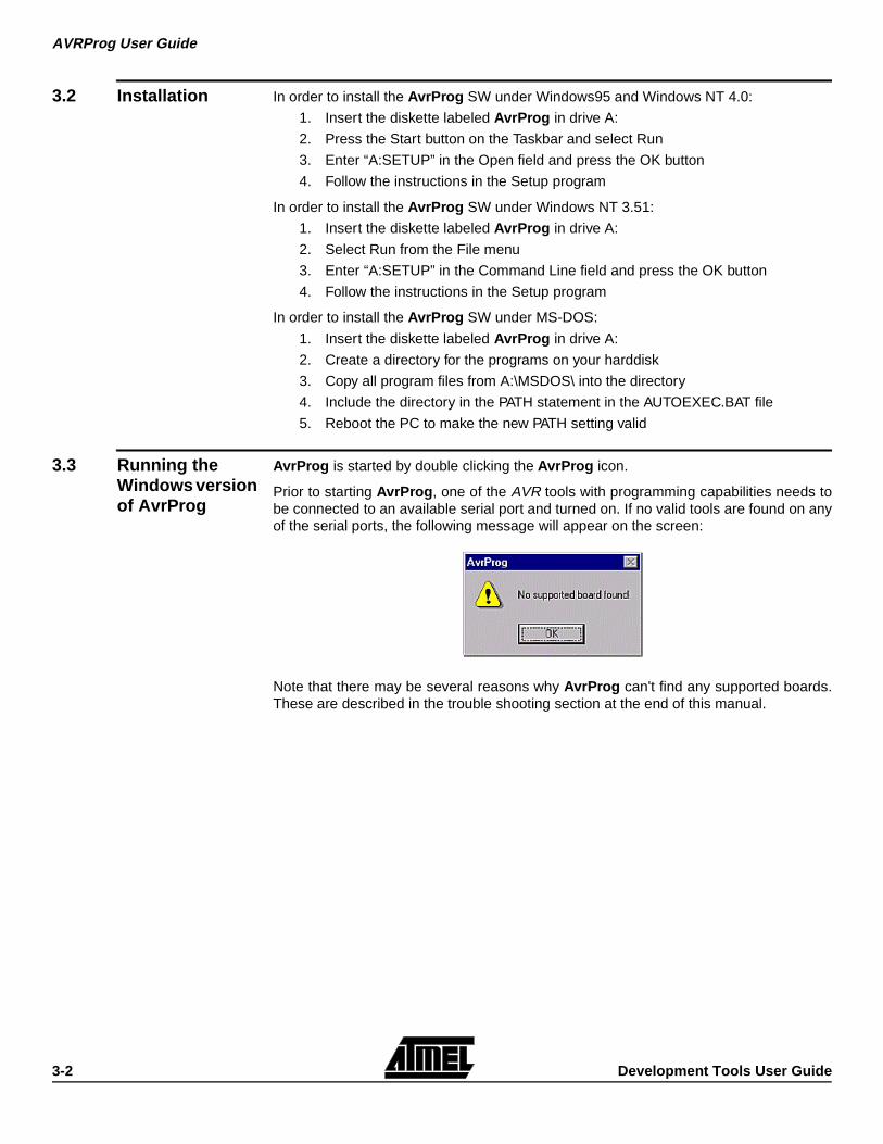
Prior to starting AvrProg , one of the AVR tools with programming capabilities needs tobe connected to an available serial port and turned on. If no valid tools are found on anyof the serial ports, the following message will appear on the screen:
Note that there may be several reasons why AvrProg can't find any supported boards.These are described in the trouble shooting section at the end of this manual.
AVRProg User Guide
Development Tools User Guide 3-3
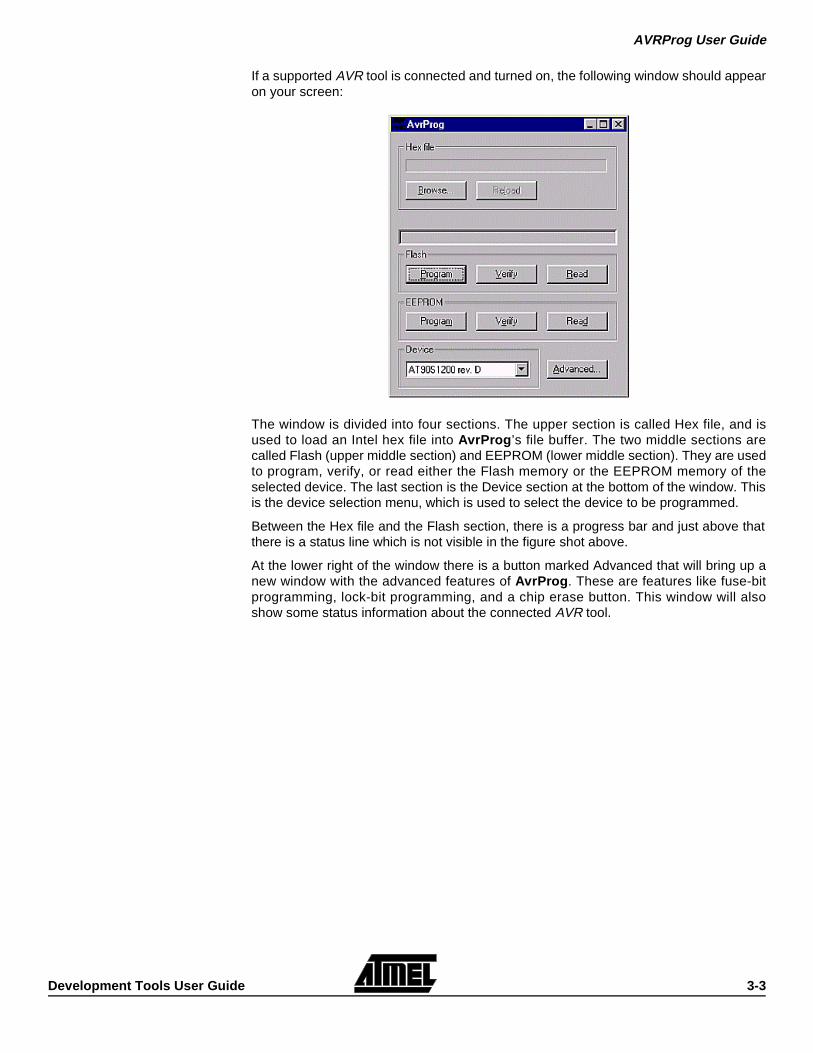
If a supported AVR tool is connected and turned on, the following window should appearon your screen:
The window is divided into four sections. The upper section is called Hex file, and isused to load an Intel hex file into AvrProg ’s file buffer. The two middle sections arecalled Flash (upper middle section) and EEPROM (lower middle section). They are usedto program, verify, or read either the Flash memory or the EEPROM memory of theselected device. The last section is the Device section at the bottom of the window. Thisis the device selection menu, which is used to select the device to be programmed.
Between the Hex file and the Flash section, there is a progress bar and just above thatthere is a status line which is not visible in the figure shot above.
At the lower right of the window there is a button marked Advanced that will bring up anew window with the advanced features of AvrProg . These are features like fuse-bitprogramming, lock-bit programming, and a chip erase button. This window will alsoshow some status information about the connected AVR tool.
AVRProg User Guide
3-4 Development Tools User Guide
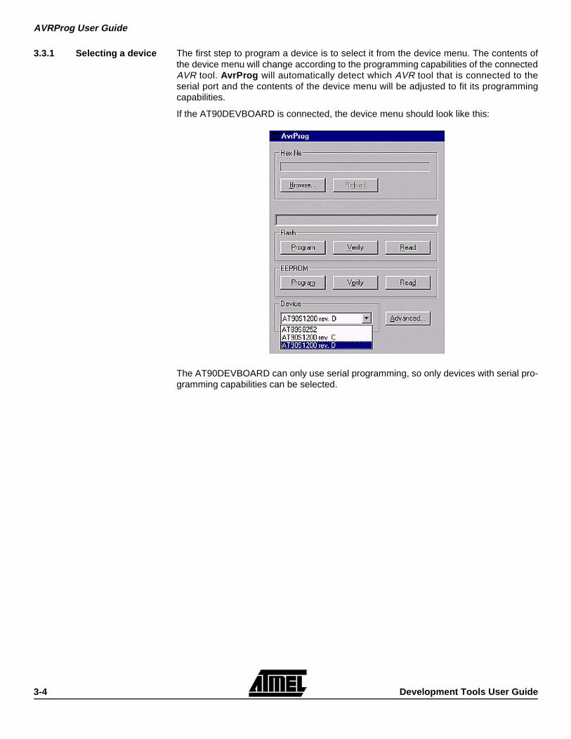
3.3.1 Selecting a device The first step to program a device is to select it from the device menu. The contents ofthe device menu will change according to the programming capabilities of the connectedAVR tool. AvrProg will automatically detect which AVR tool that is connected to theserial port and the contents of the device menu will be adjusted to fit its programmingcapabilities.
If the AT90DEVBOARD is connected, the device menu should look like this:
The AT90DEVBOARD can only use serial programming, so only devices with serial pro-gramming capabilities can be selected.
AVRProg User Guide
Development Tools User Guide 3-5
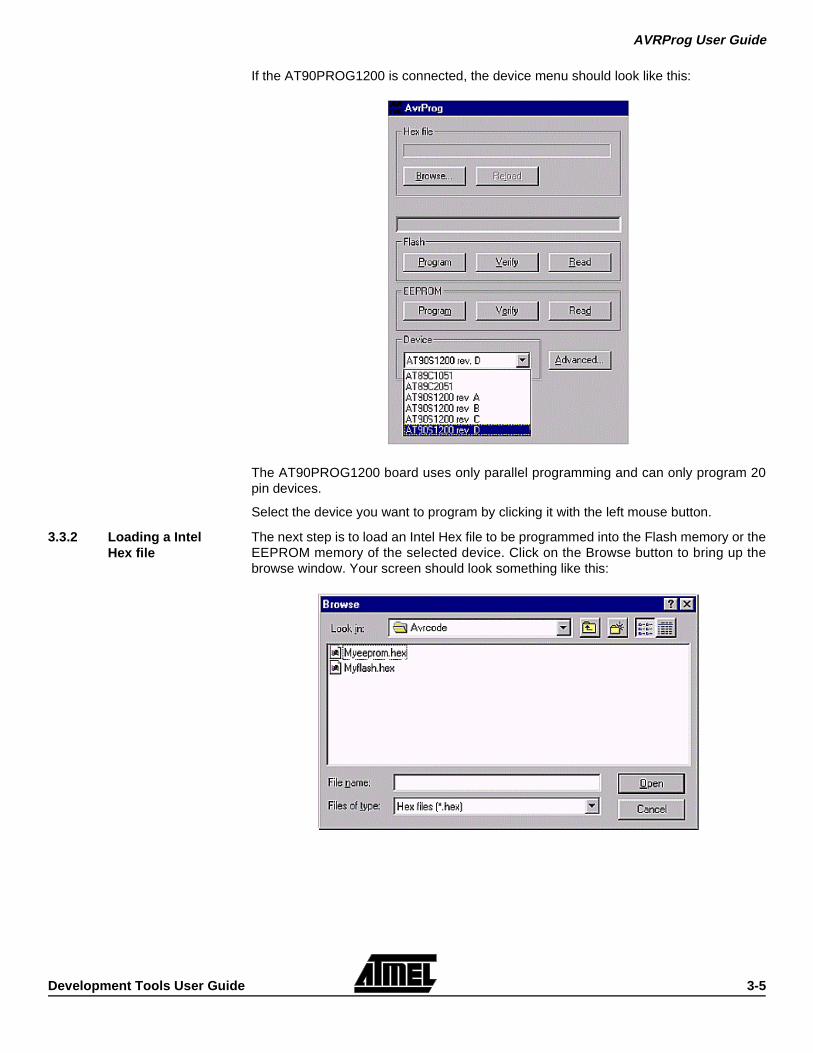
If the AT90PROG1200 is connected, the device menu should look like this:
The AT90PROG1200 board uses only parallel programming and can only program 20pin devices.
Select the device you want to program by clicking it with the left mouse button.
3.3.2 Loading a Intel Hex file
The next step is to load an Intel Hex file to be programmed into the Flash memory or theEEPROM memory of the selected device. Click on the Browse button to bring up thebrowse window. Your screen should look something like this:
AVRProg User Guide
3-6 Development Tools User Guide
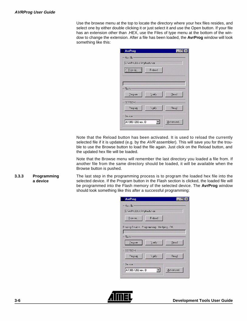
Use the browse menu at the top to locate the directory where your hex files resides, andselect one by either double clicking it or just select it and use the Open button. If your filehas an extension other than .HEX, use the Files of type menu at the bottom of the win-dow to change the extension. After a file has been loaded, the AvrProg window will looksomething like this:
Note that the Reload button has been activated. It is used to reload the currentlyselected file if it is updated (e.g. by the AVR assembler). This will save you for the trou-ble to use the Browse button to load the file again. Just click on the Reload button, andthe updated hex file will be loaded.
Note that the Browse menu will remember the last directory you loaded a file from. Ifanother file from the same directory should be loaded, it will be available when theBrowse button is pushed.
3.3.3 Programming a device
The last step in the programming process is to program the loaded hex file into theselected device. If the Program button in the Flash section is clicked, the loaded file willbe programmed into the Flash memory of the selected device. The AvrProg windowshould look something like this after a successful programming:
AVRProg User Guide
Development Tools User Guide 3-7
Note that the status line has appeared just below the Hex file section. It will show thestatus of the last action performed for a while, and then disappear. During programming,the progress bar will be active.
If the programming failed, the following message window will appear:
Note that if both the Flash memory and the EEPROM memory are to be programmed,the Flash memory always has to be programmed first and the EEPROM memory last.This is because the Flash memory programming always start with a chip erase com-mand, while the EEPROM memory programming does not.
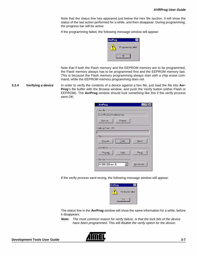
3.3.4 Verifying a device In order to verify the contents of a device against a hex file, just load the file into Avr-Prog ’s file buffer with the Browse window, and push the Verify button (either Flash orEEPROM). The AvrProg window should look something like this if the verify processwent OK:
If the verify process went wrong, the following message window will appear:
The status line in the AvrProg window will show the same information for a while, beforeit disappears.
Note: The most common reason for verify failure, is that the lock bits of the device have been programmed. This will disable the verify option for the device.
AVRProg User Guide
3-8 Development Tools User Guide
3.3.5 Read back a device In order to read back the contents of a device, just click the Read button (either Flash orEEPROM). Then the device will be read, and the contents will be saved to the filenamein the Hex file section. If the file already exist, a warning message window will appearasking if you want to replace the existing file. The message window should look some-thing like this:
If you don't want to replace the existing file, you have to open the Browse window andtype in a new filename. If you want to put the file into a directory different from the cur-rent, you should use the browse menu at the top of the window, or type in the completepath with the filename.
3.3.6 Using the advanced features
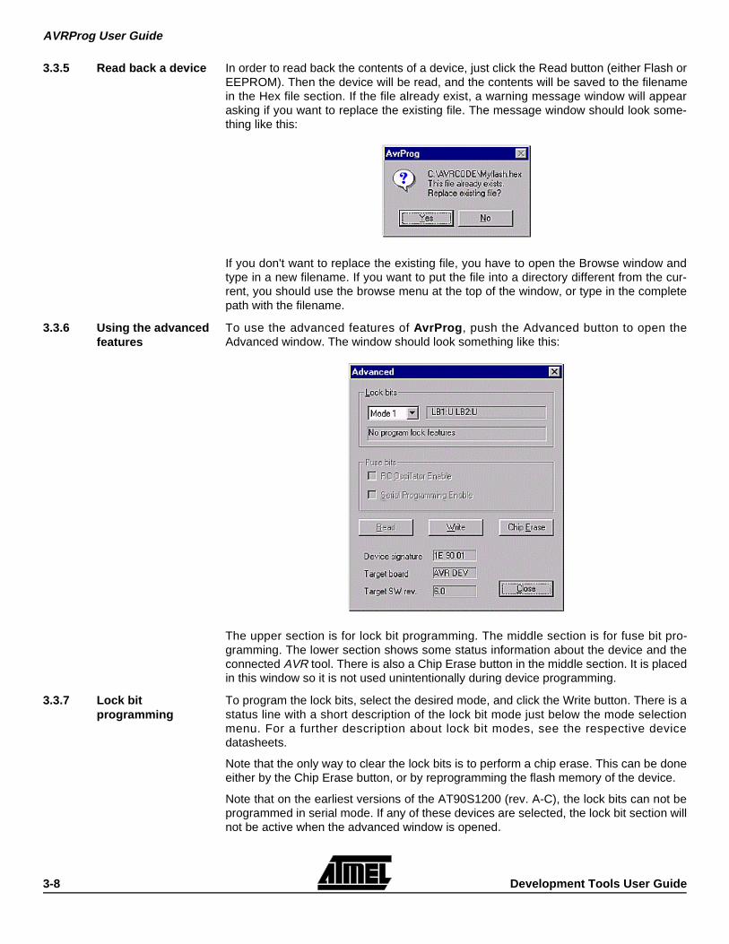
To use the advanced features of AvrProg , push the Advanced button to open theAdvanced window. The window should look something like this:
The upper section is for lock bit programming. The middle section is for fuse bit pro-gramming. The lower section shows some status information about the device and theconnected AVR tool. There is also a Chip Erase button in the middle section. It is placedin this window so it is not used unintentionally during device programming.
3.3.7 Lock bit programming
To program the lock bits, select the desired mode, and click the Write button. There is astatus line with a short description of the lock bit mode just below the mode selectionmenu. For a further description about lock bit modes, see the respective devicedatasheets.
Note that the only way to clear the lock bits is to perform a chip erase. This can be doneeither by the Chip Erase button, or by reprogramming the flash memory of the device.
Note that on the earliest versions of the AT90S1200 (rev. A-C), the lock bits can not beprogrammed in serial mode. If any of these devices are selected, the lock bit section willnot be active when the advanced window is opened.
AVRProg User Guide
Development Tools User Guide 3-9
3.3.8 Fuse bit programming
To program or read the fuse bits, parallel programming mode is required. If theAT90DEVBOARD is connected, the fuse bit section will not be active. This is becausethis tool only can perform serial programming.
When entering the advanced window, the current status of the fuse bits is read from thedevice, and shown in the fuse bit selection boxes. To force a status bit read out, use theRead button below the fuse bit section. To program status bits, select the desired com-bination and click the Write button next to the read button. Note that the lock bits willalso be programmed at the same time, unless they are set earlier. Also note that thefuse bits are NOT affected by a chip erase. The only way to change them is to repro-gram them with the Write button.
3.3.9 The Chip Erase button
When this button is clicked, the device will be erased. This will erase the contents of theFlash memory and the EEPROM memory, while the lock bits will be cleared. The fusebits are not affected by this command.
3.3.10 The Status section The upper field of the status section shows the signature bytes of the current device. Fora description of the signature bytes, see the respective device datasheets.
Note that when the lock bits are set, it is not possible to read out the signature bytes inserial mode. If parallel mode is used, the signature bytes can always be read for all lockbit modes.
The middle field of the status section shows which AVR tool that is currently connected.The current options are:
AVR DEV - is the code for the AT90DEVBOARD.
AVR PPR - is the code for the AT90PROG1200 board.
AVR ISP - is the code for the AT90ISP board.
Future codes will be:
AVR BASE - is the code for the AT90BASEPROG board.
3.4 Running the MS-DOS version of AvrProg
The MS-DOS version of AvrProg consist of six programs as listed below:
■ PROGF.EXE - MS-DOS program for Flash memory programming.
■ PROGE.EXE - MS-DOS program for EEPROM memory programming.
■ READF.EXE - MS-DOS program for Flash memory readout.
■ READE.EXE - MS-DOS program for EEPROM memory readout.
■ PROGFUSE.EXE - MS-DOS program for fuse bits programming.
■ PROGLOCK.EXE - MS-DOS program for lock bits programming.
As the Windows version of AvrProg , the MS-DOS programs will also detect which tar-get board is connected and adjust the devise list accordingly. The available devices canbe listed by entering only the program name without any command line parameters.
All programs have the following common syntax:
PROGNAME -d DEVICE -p COMPORT <other options>
Where PROGNAME is one of:
• PROGF • PROGE • READF • READE • PROGFUSE • PROGLOCK
AVRProg User Guide
3-10 Development Tools User Guide
DEVICE is one of the available devices for the target board.
COMPORT is one of the following serial ports:
• COM1 • COM2 • COM3 • COM4
Note that the MS-DOS programs do not have autodetect of the serial ports.
<other options> is program specific command line parameters.
The following examples show the use of the MS-DOS programs:
progf -d at90s1200-c -p com2 ledtest.hex
This line will program the Flash memory of an AT90S1200 rev C device at the targetboard on serial port COM2 with the hex file ledtest.hex. The device will be erased,programmed and verified.
proge -d at90s1200-b -p com2 myeeprom.hex
This line will program the EEPROM memory of a AT90S1200 rev B device at the tar-get board connected to serial port COM2 with the hex file myeeprom.hex. Thedevice will only be programmed and verified. No Chip Erase is performed.
readf -d at90s1200-a -p com2 newflash.hex
This line will read the Flash memory of a AT90S1200 rev A device at the targetboard connected to serial port COM2 and write it to the file newflash.hex. If the filealready exist, you will be notified and asked to select between overwriting the file orcancel the program execution.
reade -d at90s1200-d -p com1 neweprom.hex
This line will read the EEPROM memory of a AT90S1200 rev D device at the targetboard connected to serial port COM2 and write it to the file neweprom.hex. If the filealready exist, you will be notified and asked to select between overwriting the file orcancel the program execution.
progfuse -d at90s1200-d -p com1 -s y -r y
This line will set both fuse bits and enable both SPI programming and the internalRC oscillator on an AT90S1200 rev D device at a target board connected to serialport COM1.
proglock -d at90s1200-d -p com1 -m 3
This line will set both lock bits and disable both further programming and verificationon a AT90S1200 rev D device at a target board connected to serial port COM1.
3.4.1 Differences from the Windows version
These programs have almost the same features as the Windows version, but not all areexplicit. If a Chip Erase has to be performed, progf should be used to program an emptyhex file. The hex file must contain only “FF” data bytes to completely delete the device.
There is no other way of verifying a device with a file, other then to reprogram it.
As with the Windows version, Flash programming will perform a Chip Erase, whileEEPROM programming will not.
There is no way of reading out the signature bytes.
MS-DOS programs does not autodetect the serial port.
AVRProg User Guide
Development Tools User Guide 3-11
3.5 Troubleshooting We have tried to make these programs as error free as we can, but there are still somesituations that the programs can't resolve. The following list shows some of the situa-tions that may occur. AvrProg is used for both the Windows and the MS-DOS versionunless explicit noted.
Startup failures
If AvrProg will not start and show the “No supported boards found!” message appears,check the following list:
■ Is a power supply applied to the target board?
■ Is the power switch on the target turned on?
Note: Check if the power LED on the target is lit.
■ Is the serial cable well connected in both ends?
■ Is the serial cable of the right type?
Note: Only a one-to-one cable will work. Null modem cables with twisted RX/TX pins will NOT work.
■ Have you remembered to use the -p COMPORT option on the MS-DOS version?
■ Have you typed the correct COMPORT number for the -p option on the MS- DOS version?
■ Does more then one program accessing the serial port in a Windows environment?
A common problem with Windows environments is that two programs can not controlthe same serial port at the same time. If a DOS window is open and a program whichused the serial port has been run (even if the program has been exit), the Windowsversion of AvrProg will not work. The same situation will occur if the Windows versionof AvrProg is still open, and the MS-DOS version is run in a DOS window. The solu-tion is to close down (completely) all programs (and DOS windows) that may use ormay have used the serial port. This should solve the problem.
3.5.1 Programming/verify failures
If AvrProg show either of the “Programming failed!” or “Verified failed!” messages,check the following list:
■ Is a device inserted to the target programming socket?
■ Is the device inserted the right way in the target programming socket?
■ Are all the device pins inside the target programming socket?
■ Is the correct device inserted to target programming socket?
Check that the device is thoroughly inserted into the target board programmingsocket.
■ Have you selected the correct device in the device menu on the Windows version?
■ Have you remembered to use the -d option on the MS-DOS version?
■ Have you typed the device name right (-d option) on the MS-DOS version?
Note: If you have tried to program a device with a wrong device selection, the target board SW may crash and get totally locked. It may be seen on the AT90DEVBOARD that the yellow LED is constantly lit. On the AT90PROG1200 board, the green LED may be constantly lit. If this happens, use the respective reset buttons on the target boards, and try again. If this does not help, turn off the power to the target boards and close down the Avr-Prog programs. If the MS-DOS version is used in a DOS window in a Win-dows environment, close down the DOS window. Then turn on the power to target board again and restart AvrProg . This should resolve the situation.
Note: Parts may get damaged in your lab due to a bad ESD environment or bad handling.
AVRProg User Guide
3-12 Development Tools User Guide
NB! Always handle devices with proper ESD precautions.
If you suspect a faulty part, try several devices to check if they behave in the same man-ner. If they don't you may have a faulty part. If they do, the target board may be dam-aged. The target board should be handled with proper ESD precautions as well. Don'texceed the input power supply range of the target boards. This may cause permanentdamage to the boards. Also be very careful to avoid short circuits on the target boards.This may cause permanent damage to the boards as well.
3.5.2 Where to get help If you have any problems with the AvrProg and/or any of the AVR target boards, pleasecontact your local Atmel distributor for help. You may also send an E-mail to the AVRsupport service at [email protected]. Include all information about the problem, the Avr-Prog SW version, and the target boards used. Also include information on the PC sys-tem you are using, and which operat ing system you are using (MS-DOS,Windows95/WindowsNT).