Embed Size (px)
Citation preview

Noise, Vibration, and Harshness - Course 472 133
The pinpoint diagnosis section focuses on the procedures required to
identify the specific condition causing the complaint. It will also, in
many cases, identify the solution to resolve the condition. Situations
that require additional procedures to repair the condition are covered
in Section 4.
At this point in the diagnosis, the technician knows the symptom that
is associated with the complaint and the source of the complaint.
This part of the diagnostic section will deal with isolating the
component or condition relating to the complaint. It is organized by
source group (same as the NVH Analyzer), dealing with the most
common condition associated with each classification in that source
group.
Throughout this course we have been discussing NVH in relationship
to the senses. It only follows that the senses are one of the technicians
greatest assets in resolving NVH conditions.
Throughout all aspects of diagnosis the technician should:
• Look
• Listen
• Feel
A thorough visual inspection can provide the technician with clues or
even reveal the condition causing the complaint. Observations can uncover:
• Vehicle damage
• Previous service
• Broken, loose, missing or worn components
• Aftermarket installations
• Tire wear or damage
Examples include:
• An aftermarket exhaust system that is not built to the same
specifications as an OEM systems. These types of parts can produce
drones or body contact which will show up on the NVH Analyzer as
an engine related vibration.
• A trailer hitch installation that produces a transmission path to the
interior of the vehicle.
• Mass or dynamic dampers that have been removed for a service
procedure and not put back on the vehicle.
• A reinforcing bracket between the engine and the bell housing left
off during a previous service.
• A bell housing which has not been properly torqued.
Section 3
PINPOINT DIAGNOSIS
Introduction
Visual Inspection

Section 3
134 TOYOTA Technical Training
During a visual inspection, a stethoscope or a screw driver can be
used to amplify a vibration from a suspect component and relate it to
the complaint vibration.
Examples include:
• Lightly holding a screw driver on the metal support of a vibrating
headrest. The resulting tapping noise can be associated with a
frequency range. Knowing the frequency would help the technician
identify the source of the vibration.
• Lightly holding a screw driver on components such as an exhaust
system or suspension will amplify a vibration which can be
associated with the customer complaint.
• Care must be taken in the above procedures to avoid contact with
moving or rotating components.
• Extreme caution must be taken while diagnosing an operating
vehicle in the air to insure that the vehicle does not move.
Sophisticated automotive stethoscopes are available to assist in isolating
a complaint. Some are based on the screwdriver technique and others
are electronic with multiple clip−on microphones. The clips can be
placed in different areas of the vehicle and monitored with earphones to
determine the location of a condition.
Stethoscope
Fig. 3-1
Visual InspectionContinued

Pinpoint Diagnosis
Noise, Vibration, and Harshness - Course 472 135
A close look at the wheels and tires while a vehicle is on a lift can
reveal many possible causes of complaints. Examples include:
• Wheel covers for fit, looseness and condition.
• Lug nuts and studs for proper size, torque, fit or condition. For
example, a large locking lug nut can contribute to an imbalance
condition that would not be corrected on an off car balancer.
• OEM wheels are important for proper fit and suspension geometry.
• Incorrect tire match (brand, size or inflation).
• Rotate the tire to look for obvious conditions such as damage,
runout or lack of uniformity.
• Check the tread for wear that could indicate conditions that require
correction. For example, alignment, balance, or worn suspension
components.
• Listen for noises while rotating a wheel and tire. This will help
identify loose components, foreign matter inside a tire or worn
bearings.
• Look for evidence of tire filler or plugs that could contribute to an
imbalance.
• Lodged ice, mud or other foreign material in the rim or suspension
components.
The key to a successful visual inspection is to be familiar with the
vehicle you are diagnosing and to pay particular attention to detail.
Take the time to look closely at non complaint vehicles while performing
other services. This will provide the experience that will be useful to
quickly identify conditions that don’t normally exist on a vehicle.
Visual Inspection
Fig. 3-2
Visual InspectionContinued

Section 3
136 TOYOTA Technical Training
This part of the pinpoint section is designed to be a reference that
discusses diagnostic procedures relative to the common NVH
conditions outlined in Section 1.
Conditions are grouped into three charts. They are the vibrating
sources that are identified by the NVH Analyzer:
• Engine Symptoms Diagnostic Chart
• Driveline Symptoms Diagnostic Chart
• Wheel and Tire Symptoms Diagnostic Chart
Some conditions will appear in more than one chart. The use of
the classification flow chart, road test and a knowledge of the theory
relating to these conditions will insure that the proper pinpoint
diagnostic procedures are being used.
Refer to the end of this section for the charts.
The pinpoint diagnosis determines the specific cause of the complaint
and analyzes the possible solutions.
If a specific condition and solution is not identified at this point then
the diagnostic steps need to be reviewed for areas that may require
further investigation.
If the condition has not been resolved after carefully reviewing your
diagnostic procedures and conclusions, then technical assistance
should be consulted.
Be sure to have the details of the diagnosis ready when calling for help
(Discussed in detail later).
From the classification, road test and NVH Analyzer, it is established
that the two symptoms are steering shimmy and body booming. They
are caused by the driveline and wheels.
The NVH Analyzer indicates that the greatest amplitude is in the area of
driveline. This would make a good starting point for pinpoint diagnosis.
Pinpoint diagnosis of the driveline would include checking the following:
• Balance
• Runout
• Angle
• U−joint inspection
This order was selected because the symptoms indicate balance as the most
likely because the driveline spike was a first order vibration. (Section 1)
During the diagnosis for balance, it was found that the propeller shaft
was out of balance.
PinpointDiagnosis by
Source andSymptom Charts
NOTE
Summary
Case study: Part IV

Pinpoint Diagnosis
Noise, Vibration, and Harshness - Course 472 137
Balancing the shaft according to the procedures in Section 4, corrected
one of the symptoms of the customer complaint.
A pinpoint diagnosis of the wheel and tire vibration includes checking
the following:
• Balance
• Runout
• Condition
The symptom is a steering shimmy vibration and a distinct second and
third order vibration was noticed. Therefore, wheel balance should be
your first step. (See Section 1)
Section 4 and the 450 Suspension Systems course should be consulted
for the proper balancing procedures.
Once the pinpoint diagnosis has been performed revealing the
problem, the technician has to make a critical decision regarding
long term customer satisfaction: How to repair the vehicle effectively.
Depending on the condition or problem found, there are many resources
available such as, the repair manual, TSBs, NCFs and EWDs. In
addition, assistance is available from the FTS or the 800 hot line.
Unfortunately, in some cases, the industry has experienced a level of
repair or a short cut procedure that is below standard and not in line
with long term customer satisfaction. This usually occurs as a result of
frustration due to a poor diagnostic procedure. Hopefully, the
diagnostic procedures outlined in this course and the NVH Analyzer
will minimize those frustrations.
Section 4 of this course deals with the common repair techniques used
in NVH repair. Many of the other NVH repairs are standard service
procedures detailed in the repair manuals.
Current vehicles are very complex and the amount of information
required to successfully repair a vehicle the first time is
enormous. Toyota recognizes this fact and has established systems to
provide the technician with assistance. The areas for assistance are:
• TAS 800 hot line
• Field Technical Specialist (FTS)
During NVH diagnosis the possible conditions vary greatly and may or
may not be easily serviceable by the technician. By using TAS, technicians
can tap into resources which provide a data base of similar situations
and successful solutions. Outside help can also provide some objective
clarity to our diagnostic process and point out additional areas to examine.
Case study: Part IVContinued
Choose andPerform theAppropriate
Repair
TechnicalAssistance
Section 3
138 TOYOTA Technical Training
It is important to look at assistance as an additional tool and not a
last resort or a sign of failure.
In order for assistance to be successful, however, there are key factors
that must be in place prior to making your call:
• Good communication skills
• Organized diagnosis procedure
• Reliable data
Most assistance is done over the phone. The listener cannot verify the
complaint or follow the diagnostic procedure on the vehicle and
therefore must rely on what they are told. The use of standardized
terms is critical. The symptoms and description must be clearly
understood by both parties.
When both the technician and the engineer use the same diagnostic
procedure, then the engineer can follow along in the same organized
manner as the technician. The engineer can predict the steps and
not get confused in trying to sort out a random diagnosis. At specific
points in the discussion, the engineer will be looking for data that will
support the decision process.
The engineer can now point out conditions to consider, in the diagnosis
or the data, which will redirect the technician toward a successful solution.
He may confirm your conclusions and recommend further
assistance to deal with a condition that is not serviceable by the
technician.
Nobody likes to get �buried" in a job and customers do not like the
service experience associated with the inability to satisfactorily resolve
a complaint. As the service experience becomes unpleasant to the
customer, they often become more difficult to satisfy.
The quicker the technician resolves the complaint, or identifies the
need for outside help, the better the service experience for all involved.
It is important to note that jumping to assistance without making a
concerted effort to follow the above procedures is also a waste of
time. Without specific information, technical assistance cannot help,
and will direct you to perform the procedures.
Technical assistance is an option for a technician when help is needed
in diagnosing a serviceable complaint or in identifying when outside
technical support is necessary.
The key is to have solid diagnostic data available and to use technical
assistance as soon as it is necessary.
The object is to get the complaint resolved to ensure customer
satisfaction and not wait until it is a last resort or too late.
TechnicalAssistance
Continued
Summary

Pinpoint Diagnosis
Noise, Vibration, and Harshness - Course 472 139
The complaints on the 4Runner are easily diagnosed and resolved by
the technician. Technical assistance should not be necessary in this case.
If the conditions found did not exist, yet there was still a verifiable
complaint, then assistance should be consulted using the above criterion
and the support documentation from the diagnosis.
The data collected while verifying and measuring the complaint will be
useful as a basis for comparison of the effectiveness of the repair.
In many cases the vibration or sound will never completely go away.
The objective may be to lower the amplitude to an acceptable level. The
acceptable level may change for a customer as they become tuned into
the complaint, especially if they are experiencing some frustration with
the service experience. Simply showing the customer graphic printouts
of the improvement may satisfy them.
The advantage of hard data is to objectively provide a comparison to
show improvement or the acceptable levels of other similar vehicles.
When the complaint is successfully resolved and verified, then the
vehicle is ready to be returned to the customer. You will have the
confidence of knowing the diagnosis and repair was done right the first
time and you will have the documentation to prove it.
If you cannot objectively verify that the complaint has been resolved,
then the opportunity exists to go back through the process to find the
condition, without the customer’s involvement.
A test drive with the NVH Analyzer verified that the complaint was
resolved when a comparison is made with the data collected during the
road test.
4Runner ScenarioScreen Print
Fig. 3-3
The next section of the course will deal with the common NVH repair
techniques in greater depth.
Case study: Part V
Verify that thecomplaint has been
satisfactorilyresolved
Summary
Case study:Conclusion

Section 3
140 TOYOTA Technical Training
Engine Symptoms Pinpoint Diagnosis
Accelerator Pedal Vibrations occur at frequen−
cies associated with engine speed.
They are usually of low amplitude and not in
the direction of the pedal stroke.
They can usually be duplicated when the engine
reaches a specific RPM regardless of vehicle
speed.
If the vehicle is moving, the vibrations will go
away when coasting in neutral.
Accelerator PedalVibrations
Fig. 3-4
Pinpoint diagnosis includes inspection of the engine running condition at:
• the RPM recorded during the verification and classification sections
• idle quality both normal and under load (A/C, P/S, electrical load)
• fast idle quality both normal and under load
• cruise RPM
Pinpoint inspection also includes checking:
• the engine, transmission and accessories for contact with the body
• throttle lever and accelerator cables
− check brackets, bushing and grommet
− disconnect cable clamp and A/T throttle cable and see if the vibration
changes. If the vibration disappears when the A/T throttle cable is
disconnected then inspection of the transmission may be required
• accelerator pedal
− play or looseness
− return spring and free play
− mass damper (if equipped)
A complete TCCS diagnosis may be required to deal with engine
driveability conditions that may contribute to engine related vibrations.
Symptom Accelerator Pedal Vibration
Description
PinpointDiagnosis
Remarks

Pinpoint Diagnosis
Noise, Vibration, and Harshness - Course 472 141
Shift lever vibrations are generated by engine
torque fluctuations or imbalance of revolving or
reciprocating engine components.
They occur at particular, high engine RPM and
may be amplified by imbalance in the propeller
shaft or shaft joint angle on a FR vehicle.
They may also be associated with a �buzz"
sound.
Shift Lever VibrationsFig. 3-5
Inspection and repair of shift lever vibrations include the same engine
condition inspections outlined in the accelerator cable vibration section,
with the addition of the following:
Inspect the slit clearance
• check the engine and transmission
mounting for:
− overall alignment
− contact or looseness at mounting points
− mount slit clearance
− deterioration of rubber quality due to a
leak
MountsFig. 3-6
Symptom Shift Lever Vibrations
Description
PinpointDiagnosis
Section 3
142 TOYOTA Technical Training
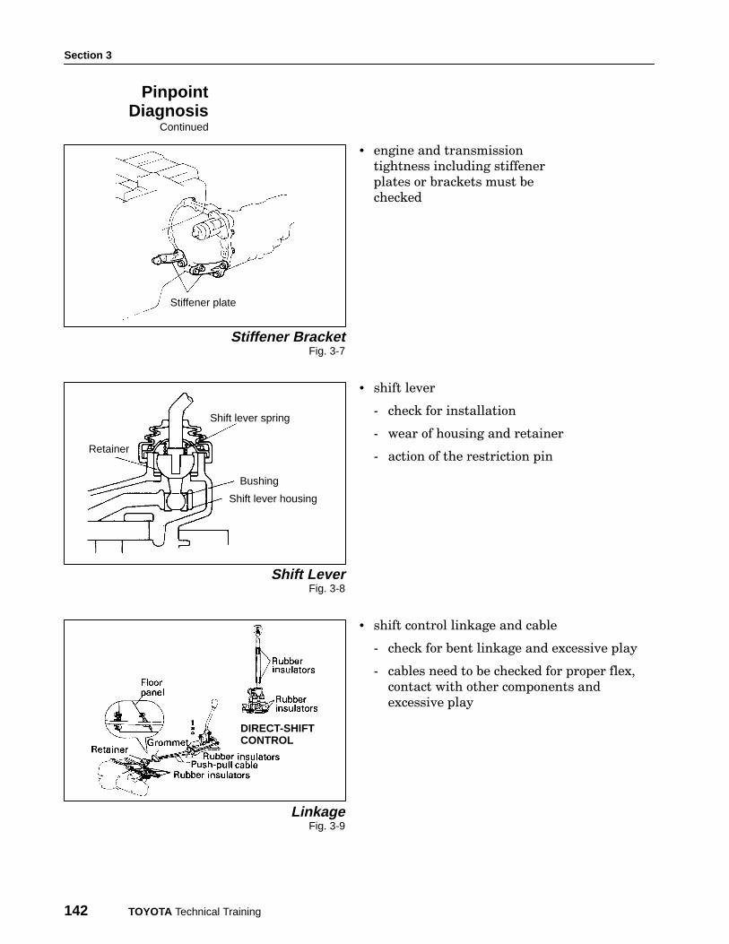
Stiffener plate
• engine and transmission
tightness including stiffener
plates or brackets must be
checked
Stiffener BracketFig. 3-7
Bushing
Shift lever housing
Shift lever spring
Retainer
• shift lever
− check for installation
− wear of housing and retainer
− action of the restriction pin
Shift LeverFig. 3-8
• shift control linkage and cable
− check for bent linkage and excessive play
− cables need to be checked for proper flex,
contact with other components and
excessive play
LinkageFig. 3-9
DIRECT-SHIFTCONTROL
PinpointDiagnosis
Continued

Pinpoint Diagnosis
Noise, Vibration, and Harshness - Course 472 143
• transmission condition
− check for play in the shift fork and shaft
− inspect each gear and thrust clearance
− shift fork to hub sleeve clearance
TransmissionCondition
Fig. 3-10
The two piece oil pans on later model vehicles
have been designed to improve NVH character−
istics. Stiffener plates are not used on these ve−
hicles.
Two Piece Oil PanFig. 3-11
Remarks

Section 3
144 TOYOTA Technical Training
Engine noise is engine speed related and may
require a change in load.
Engine NoiseFig. 3-12
Engine noise is most commonly diagnosed by searching for the source
visually or with a stethoscope.
Other techniques such as, removing a plug wire and grounding it or
disconnecting an injector, can help identify the location of an internal
engine noise. By changing the firing load in a cylinder, noises from a
piston, piston pin or rod bearing condition may change, identifying a
cylinder causing the complaint.
Vehicles with multiple belts can be diagnosed by removing the belts one at
a time until the condition changes. Accessories associated with the belt
and the condition of the belt should be checked. Components include:
P/S vane pump
Alternator
A/C compressor
• fan
• fan shroud
• alternator
• water pump
• A/C compressor
• idler pulley
• P/S pump
Engine AccessoriesFig. 3-13
Perform diagnosis quickly when belts are removed so that problems
such as overheating will not occur.
Symptom Engine Noise
Description
PinpointDiagnosis
CAUTION

Pinpoint Diagnosis
Noise, Vibration, and Harshness - Course 472 145
The air intake system can also be a source of both noise and vibrations.
This system is designed to deliver filtered, fresh air to the engine with
minimal noise. Many systems incorporate resonators to accomplish
noise reduction.
Cool air intake
Intake resonator A technician can inspect the air intake system:
• for the proper components properly
connected
• to see if the complaint can be modified by
pushing on or disconnecting components or
hoses
• for proper mounting and mount condition
• for foreign material that can make noise or
cause an obstruction
Intake SystemFig. 3-14
The exhaust system is discussed in many areas of this course as a
possible transmitter of engine vibration and noise through body
contact. You should also consider the possibility of exhaust restriction
as a potential noise source. Vehicles with this condition would also
exhibit power loss under load. A vacuum gauge is very helpful in
pinpointing a restricted exhaust condition.
PinpointDiagnosis
Continued
Remarks

Section 3
146 TOYOTA Technical Training
Clutch judder can be reproduced during partial
clutch engagement when the vehicle encounters
rolling resistance, for example, climbing a
grade. This condition can be simulated by light−
ly applying the brake during clutch engage−
ment.
Clutch JudderFig. 3-15
Engine running condition needs to be considered as well as the
condition of the motor mounts when troubleshooting engine noise.
Bushing
Suspension bushings need to be inspected by
prying them apart and checking the slits pro−
vided to minimize vibration and noise. The sus−
pension system can be a transmission path for
normal vibration during clutch engagement.
Bushing Contacts andSlits
Fig. 3-16
Symptom Clutch Judder
Description
PinpointDiagnosis
Pinpoint Diagnosis
Noise, Vibration, and Harshness - Course 472 147
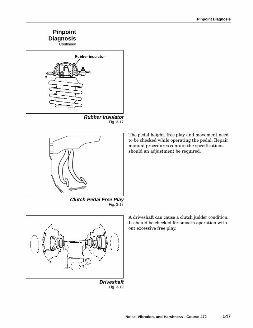
Rubber InsulatorFig. 3-17
The pedal height, free play and movement need
to be checked while operating the pedal. Repair
manual procedures contain the specifications
should an adjustment be required.
Clutch Pedal Free PlayFig. 3-18
A driveshaft can cause a clutch judder condition.
It should be checked for smooth operation with−
out excessive free play.
DriveshaftFig. 3-19
PinpointDiagnosis
Continued

Section 3
148 TOYOTA Technical Training
When external inspections do not produce the
condition then inspection of the clutch assembly
is necessary. This includes the following:
• Toyota clutch components are specifically de−
signed to meet the torsional characteristics
required for torque fluctuation of the engine.
These components are recommended to en−
sure the best operation of the clutch.
• the clutch release lever needs to be checked
for mounting, alignment and wear.
• the release bearing should be checked for
proper alignment and smooth movement. Re−
taining clips should also be checked.
• the pressure plate assembly and diaphragm
spring must be inspected for:
− wear
− spring tension and alignment
− evidence of heat that would effect the
temper and tension of the spring
− evidence of discoloration or hard spots on
the pressure plate and flywheel
− scores, grooves or runout in the pressure
plate or flywheel
− warpage of the pressure plate mounting
assembly due to uneven torque or loose
mounting bolts
− clutch disc surface condition, rivets, torsion
springs, and spline must be looked at
closely
• close inspection of the transmission input
shaft spline and pilot bearing also reveal the
cause of the complaint
Clutch AssemblyFig. 3-20
Clutch DiscFig. 3-21
PinpointDiagnosis
Continued
Pinpoint Diagnosis
Noise, Vibration, and Harshness - Course 472 149
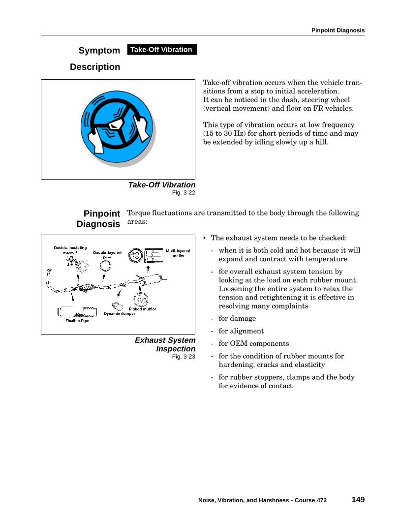
Take−off vibration occurs when the vehicle tran−
sitions from a stop to initial acceleration.
It can be noticed in the dash, steering wheel
(vertical movement) and floor on FR vehicles.
This type of vibration occurs at low frequency
(15 to 30 Hz) for short periods of time and may
be extended by idling slowly up a hill.
Take-Off VibrationFig. 3-22
Torque fluctuations are transmitted to the body through the following
areas:
• The exhaust system needs to be checked:
− when it is both cold and hot because it will
expand and contract with temperature
− for overall exhaust system tension by
looking at the load on each rubber mount.
Loosening the entire system to relax the
tension and retightening it is effective in
resolving many complaints
− for damage
− for alignment
− for OEM components
− for the condition of rubber mounts for
hardening, cracks and elasticity
− for rubber stoppers, clamps and the body
for evidence of contact
Exhaust SystemInspection
Fig. 3-23
Symptom Take-Off Vibration
Description
PinpointDiagnosis

Section 3
150 TOYOTA Technical Training
• Engine mounts can be inspected as in other
engine related NVH diagnosis. Engine torque
type complaints relating to mounts or contact
can be duplicated by rocking the power train.
This is done by increasing the RPM with the
vehicle in gear, wheels blocked and the brakes
applied. Both drive and reverse should be
used.
Engine MountingFig. 3-24
• The drive shafts must rotate smoothly with−
out excessive play. Both conditions are sensi−
tive to torque fluctuations.
• Take−off vibrations that are felt in the floor
may be produced by the propeller shaft and
transmitted through the center carrier. An
inspection of the propeller shaft includes
checks for:
− play at the extension housing and yoke
− missing weight (look for a trace of a spot
weld)
− joint phase
− smoothness and runout (rotate shaft
manually)
− center bearing alignment both vertically
and horizontally
Propeller ShaftInspection
Fig. 3-24
Do not perform the engine torque test at high
RPM or for extended periods due to overheating
of the engine, torque converter or transmission.
See Section 4 for details on propeller shaft
inspection and repair.
PinpointDiagnosis
Continued
Remarks
CAUTION

Pinpoint Diagnosis
Noise, Vibration, and Harshness - Course 472 151
Crank vibration occurs at a low frequency (5 − 15 Hz) during engine
cranking.
Engine related conditions that impact torque fluctuation during
cranking include:
• uneven compression between cylinders (diagnose with a power
balance and/or compression test)
• ignition timing and excessive engine temperature (The complaint
verification section is very helpful in this area because the
complaint will not occur every time the engine is cranked.)
• hydraulic lock in a cylinder due to a leaking injector or head gasket
• worn starter bushings (diagnose with a starter current draw test)
Transmission of normal cranking vibrations through the exhaust
system and engine mounts are diagnosed the same as in the previous
engine conditions.
(10 − 50 Hz)
Idle vibrations require the same diagnosis procedures as cranking
vibrations with the addition of an engine idle quality inspection.
They may be more noticeable when the engine is under load, for
example, when in gear or with the A/C on. Vehicles with
transverse−mount engines are more sensitive to idle vibrations that are
transmitted through the exhaust system.
If it is found that an engine performance condition is the cause of the
symptoms then a thorough TCCS diagnosis is recommended.
Symptom Crank Vibration
Description
PinpointDiagnosis
Symptom Idle Vibration
Description
PinpointDiagnosis

Section 3
152 TOYOTA Technical Training
Body booming noise is a symptom that can be caused by engine,
driveline and tire/wheel conditions.
Be sure to check the details in all three source areas when diagnosing a
body booming symptom.
Establishing whether a symptom is engine speed related or vehicle
speed related is the first step in determining which area to focus the
pinpoint tests. Engine related symptoms can be heard while increasing
the engine RPM, therefore, the engine can be eliminated as the cause if
the noise is heard while coasting in neutral.
The exterior of the body should be checked for conditions that may
resonate with normal vibrations. A thorough visual inspection is
important to find conditions such as fit, looseness or damage of body
components. An overall look at the vehicle ride height will help you
identify conditions such as uneven tire inflation.
Inspection for engine noise should be performed through all operating
engine speeds including the RPM that produces the most noise. All
engine driven accessories should be operated to see if they contribute to
the condition.
A technician should look at the belts, component fit, rattle or contact
and any foreign material lodged between components. Engine mounts
should be checked during this inspection as mentioned before.
While duplicating the noise, see if it changes while modifying the
intake air duct system, such as disconnecting or pushing on it.
The exhaust system is also an area that will cause a body booming
noise which is engine related. The system should be checked for
damage, mounting, contact with the body and clamp condition. As
stated before, the system should be checked to determine that it is
properly designed for the vehicle.
An exhaust system changes shape with temperature and should be
checked in all temperature ranges. Modifying the system by removing
hangers or placing a jack under it to keep it stationary will also help to
isolate the exhaust system as the cause.
Symptom Body Booming Noise
Description
NOTE
PinpointDiagnosis

Pinpoint Diagnosis
Noise, Vibration, and Harshness - Course 472 153
Body beating noise requires two vibrations as
discussed in Section 1.
It is being addressed in the engine area because
the vibrations generated by the engine can be
one of the two vibrations involved.
Engine vibrations contributing to body beating
include imbalance and torque fluctuation. Im−
balance is a first order vibration, while torque
fluctuation is a second order vibration on four
cylinder engines and third order on six cylinder
engines.
A vibration from the engine area combined with
one from the driveline or wheel will create the
body beating symptom. Resolving this type of
complaint can be done by eliminating either one
of the vibrations or reducing both of them to a
minimal level.
Duplicating a beating noise requires a slow
change in engine RPM while waiting for the
symptom to occur. A beating noise is most no−
ticeable at a frequency between 2 and 6 Hz
therefore the technician needs to hold a
constant speed long enough for the symptom to
appear.
Body beating is a cyclical sound which will occur
at a particular RPM. This RPM should be iden−
tified during verification of the complaint.
Both engine speed and vehicle speed are re−
quired to create this symptom, therefore the ve−
hicle speed should also be identified during veri−
fication for diagnosis of the second vibration.
BeatingFig. 3-26
The specific pinpoint tests for the engine vibration are the same as
those for body booming noise. In addition, the engine and transmission
tightening and the stiffener bracket should also be inspected.
Symptom Body Beating Noise
Description
PinpointDiagnosis

Section 3
154 TOYOTA Technical Training
Driveline Pinpoint Diagnosis
Transmission gear whine and Differential gear
whine are very similar sounds that are not like−
ly to be noticed on the NVH Analyzer. The fre−
quency range is between 400 and 3k Hz for
transmission gear whine and 400 to 1500 Hz for
differential gear whine which are above the 500
Hz range of the NVH Analyzer.
Gear WhineFig. 3-27
To pinpoint the source of gear whine, first determine which symptom
exists. The road test will be the most useful technique for this step.
• Operate the vehicle at the speed the whine is most noticeable.
• Then change the speed of the vehicle to see if the noise is speed
related.
• Next change gears to determine if the noise changes with different
gear selections.
• Note the level of the noise when the gear ratio is 1:1. At this ratio
the power flow is direct through the transmission and the load on
the gears is the minimal.
Differential gear whine is vehicle speed related and will not change
with different gear selections.
The transmission path is an important area of pinpoint diagnosis for
both transmission and differential gear whine. Inspection of
components that could transmit noise to the passenger compartment
will often resolve the complaint.
Inspection of body sound insulators is also important in gear noise
diagnosis. The technician should look for the following:
• gaps in body panels
• damage to grommets, body molding, boots and seals
• condition of sound absorbing materials such as asphalt sheets,
silencer pads and floor carpets.
Symptom Transmission Gear Whine and Differential Gear Whine
Description
PinpointDiagnosis

Pinpoint Diagnosis
Noise, Vibration, and Harshness - Course 472 155
Input Shaft4TH Gear
3RD Gear Reverse Gear
Output Shaft
5TH GearClutch Hub and Hub Sleeve
2ND Gear1ST Gear
If it is determined that the noise is coming
from the transmission or differential, careful
inspection of the gears as well as the bearings
is important.
Gear whine and bearing noise are very similar,
depending on the condition of the bearings, and
difficult to isolate in a test drive. Bearing condi−
tion could also have an effect on gear mesh and
condition.
A thorough understanding of the transmission
power flow, will help anticipate the gears and
bearings causing the problem during the test
drive.
The repair manual is an important resource to
consult when diagnosing and repairing internal
transmission and differential noises. Procedures
and specifications are available to insure the
component is repaired properly the first time.
GearsFig. 3-28
PinpointDiagnosis
Continued
Remarks

Section 3
156 TOYOTA Technical Training
Body booming noise is discussed in the engine
pinpoint diagnosis chart specific to causes that
are engine related. In this area, pinpoint diag−
nosis of body booming noise conditions related
to driveline are discussed.
U-Joint PhaseFig. 3-29
A visual inspection includes checking for proper U−joint phase. Fig.
3−29 shows the proper position of the U−joints on the different shafts.
On a 3−joint propeller shaft the center bearing position must be
checked for vertical and horizontal alignment.
The shafts should be rotated, checking for free
movement, smoothness, unusual noises or loose−
ness. Visual inspection for alignment, damage
or contact with other components such as cables
or the exhaust may pinpoint the cause of the
complaint.
Specific details on the following are covered in
Section 4 of this course:
• driveline balancing
• runout measurement and correction
• angle adjustment and repairCenter CarrierFig. 3-30
Symptom Body Booming Noise
Description
PinpointDiagnosis

Pinpoint Diagnosis
Noise, Vibration, and Harshness - Course 472 157
The NVH portion of the Diagnostic Tester is very helpful in isolating
the source of the vibration including differentiating between balance,
runout and angle conditions.
• First order (primary component) driveline vibration is associated
with balance or runout conditions.
• Second order (secondary component) driveline vibration is
associated with U−joint condition such as angle, tightness or
looseness.
As discussed in the engine body beating noise section, it requires two
vibrations to cause a complaint. The driveline is one of the possibilities
to consider, especially if the NVH Analyzer indicates a strong vibration
in the driveline area.
Pinpoint diagnosis of a body beating noise is the same as the pinpoint
diagnosis of the driveline for body booming noise.
PinpointDiagnosis
Continued
Remarks
Symptom Body Beating Noise
Description
PinpointDiagnosis
Section 3
158 TOYOTA Technical Training
Wheel Pinpoint Diagnosis
Body Shake, Steering Flutter and Steering Shimmy complaints all
involve pinpoint diagnosis of the same components. The condition of
the component is what determines which of the symptoms occur.
The wheels and tires are a good place to start especially if the NVH
Analyzer identifies this area as the generating force of the vibration.
Tire and wheel inspection includes:
• Checking all four tires for the same manufacture, size, and
specifications. Proper tire pressure is also an important item to confirm.
• Looking for damage, deformation and wear. The technician should
also rotate the tire and wheel assembly, looking at both the side
wall and tread, to reveal obvious conditions caused by internal tire
damage, flat spots or runout.
• Feeling the tread for unusual wear patterns that may be abnormal.
This will direct the technician to conditions that need to be corrected.
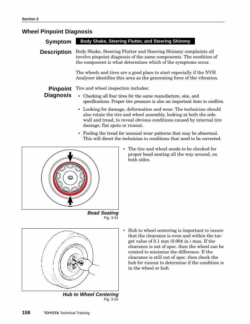
• The tire and wheel needs to be checked for
proper bead seating all the way around, on
both sides.
Bead SeatingFig. 3-31
• Hub to wheel centering is important to insure
that the clearance is even and within the tar−
get value of 0.1 mm (0.004 in.) max. If the
clearance is out of spec. then the wheel can be
rotated to minimize the difference. If the
clearance is still out of spec. then check the
hub for runout to determine if the condition is
in the wheel or hub.
Hub to Wheel CenteringFig. 3-32
Symptom Body Shake, Steering Flutter, and Steering Shimmy
Description
PinpointDiagnosis

Pinpoint Diagnosis
Noise, Vibration, and Harshness - Course 472 159
There are two types of runout to check on the tires, wheels and hubs:
• radial
• lateral
Radial runout is the change in the radius as
it rotates. It is measured with a dial indicator
that is mounted in a stationary position, paral−
lel with the rotating plane. Check radial runout
through one complete 360° rotation of the tire
and wheel assembly.
Lateral runout is the side to side movement.
Wheel and Tire RunoutFig. 3-33
A dial indicator is used to measure the runout
as the tire and wheel assembly is rotated 360°.
The balance of rotating components must be
checked including the tire, wheel, hub, drum or
rotor.
• Tires and wheels are commonly balanced off
the car which takes into consideration irregu−
larities of the tires and wheels
• Dynamic balancing (wheel and tire in motion)
is recommended for accuracy as compared to
static or bubble balancing
• On car balancing or finish balancing not only
includes tires and wheels but also checks ev−
erything that rotates (ie: hub, rotor/drum and
bearings).
Rim and Tire RunoutFig. 3-34
PinpointDiagnosis
Continued

Section 3
160 TOYOTA Technical Training
While performing an inspection, the technician should keep in mind
components in other areas that will resonate at wheel speed. This
includes many components in the steering and suspension systems.
Steering system component checks include:
• ball joint play
• leakage
• steering linkage play or damage
• steering damper condition
• condition of the rubber bushings
Suspension system components checks include:
• condition of suspension arms and bushings
• condition of the springs
• wheel bearing adjustment
• shock absorber inspection for leaks, bushing condition and proper
operation
Tire wear may cause a vibration but may be the result of another
condition such as incorrect wheel alignment or worn components. The
technician needs to do a thorough inspection to be sure the original
cause of the condition is repaired.
Details on measuring and correcting runout are discussed in Section 4.
Details on balancing are also included in Section 4.
PinpointDiagnosis
Continued
Remarks

Pinpoint Diagnosis
Noise, Vibration, and Harshness - Course 472 161
Riding Comfort, Harshness, Road Noise and
Tire Pattern Noise are all different symptoms
with different characteristics as discussed in
Section 1. The generating forces in these condi−
tions are caused by contact with the road which
we have no control or cannot change. What
we have control over is the transmission path
of the impact through the vehicle.
The transmission path and the components to
inspect are the same for all four of the above
conditions, therefore the pinpoint diagnosis will
cover the same systems and components.HarshnessFig. 3-35
The components in these areas to check are also
similar to the inspections discussed in previous
pinpoint diagnosis of tire and wheel vibrations:
• tire and wheel
• suspension
• body sound insulators
In all pinpoint diagnosis it is important to look
for changes from the manufacturer’s original
condition.
For example:
Low aspect ratio/profile tires are popular for
appearance to some customers. These tires do
not have the same ride characteristics as the
original profile tire. The customer will feel a
greater impact from road irregularities.
Low Profile TireFig. 3-36
Symptom Riding Comfort, Harshness, Road Noise, Tire Pattern Noise
Description
PinpointDiagnosis

Section 3
162 TOYOTA Technical Training
Brake vibration occurs only when the brakes are applied. As a result
the technician can go directly to pinpoint diagnosis.
Pinpoint diagnosis of this condition includes in−
spection of the:
• pedal for lateral play
• rotor for surface condition such as rust,
grooves, glazing, hard spots, evidence of over−
heating and evidence of poor surface condi−
tion
• rotor runout and parallelism (target value 0.1
mm (0.004 in.) or less)
• drum to shoe contact surface condition for
rust, grooves, glazing, hard spots, evidence of
overheating and evidence of poor surface con−
dition.
• Wheel bearing adjustment and condition
needs to be checked
• Shoes and Pads must be checked for glazing,
cracks, uneven wear and proper installation.
OEM is recommended to insure the proper
function and friction characteristics.
• Disc brake hardware should be checked for
looseness, wear, dirt, leaks and operation.
• Drum brake hardware checks include proper
assembly, spring tension, damage, leaks, wear
and operation.
• The surface of the wheel that mounts to the
hub should be flat with no cracks. target val−
ue − 0.1 mm (0.004 in.) or less. It is important
to check hub and axle runout before making
corrections for rotor, drum runout or wheel
and tire runout. A bent axle will cause all of
the components to indicate a runout condition
if checked while on the vehicle.
Rotor Runout and ThicknessFig. 3-37
Drum RunoutFig. 3-38
Axle RunoutFig. 3-39
Symptom Brake Vibration
Description

Pinpoint Diagnosis
Noise, Vibration, and Harshness - Course 472 163
Brake squeak is associated with the contact of the pads/shoes to the
rotors/drums.
Inspection and repair involves inspection of:
• The surface of the linings and pads for wear,
hardness, and shine.
• Pad/shoe contact, by placing them against the
rotor/drum surface and noting even contact.
Pad and Shoe ConditionFig. 3-40
• Brake component tightness including the
backing plate, hub and rotor, caliper mount−
ing and slide pins.
Component ConditionFig. 3-41
Symptom Brake Squeak
Description
Section 3
164 TOYOTA Technical Training
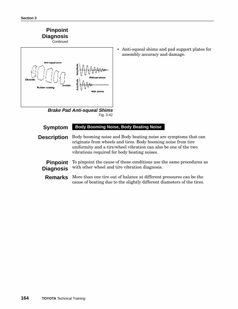
• Anti−squeal shims and pad support plates for
assembly accuracy and damage.
Brake Pad Anti-squeal ShimsFig. 3-42
Body booming noise and Body beating noise are symptoms that can
originate from wheels and tires. Body booming noise from tire
uniformity and a tire/wheel vibration can also be one of the two
vibrations required for body beating noises.
To pinpoint the cause of these conditions use the same procedures as
with other wheel and tire vibration diagnosis.
More than one tire out of balance at different pressures can be the
cause of beating due to the slightly different diameters of the tires.
PinpointDiagnosis
Continued
Symptom Body Booming Noise, Body Beating Noise
Description
PinpointDiagnosis
Remarks