Embed Size (px)
Citation preview
September 2, 2009
SECTION 33 11 00 Page 1
SECTION 33 11 00
WATER DISTRIBUTION
March 3, 2014
PART 1 GENERAL
1.1 REFERENCES
The publications listed below form a part of this specification to the extent referenced. The
publications are referred to within the text by the basic designation only.
AMERICAN ASSOCIATION OF STATE HIGHWAY AND TRANSPORTATION
OFFICIALS (AASHTO)
AASHTO HB-17 (2002; Errata 2003; Errata 2005) Standard Specifications for
Highway Bridges
AMERICAN RAILWAY ENGINEERING AND MAINTENANCE-OF-WAY
ASSOCIATION (AREMA)
AREMA Eng Man (2007) Manual for Railway Engineering
AMERICAN WATER WORKS ASSOCIATION (AWWA)
AWWA B300 (2004) Hypochlorites
AWWA B301 (2004) Liquid Chlorine
AWWA C104/A21.4 (2003) Cement-Mortar Lining for Ductile-Iron Pipe and
Fittings for Water
AWWA C105/A21.5 (2005) Polyethylene Encasement for Ductile-Iron Pipe
Systems
AWWA C110/A21.10 (2003) Ductile-Iron and Gray-Iron Fittings for Water
AWWA C111/A21.11 (2000) Rubber-Gasket Joints for Ductile-Iron Pressure Pipe
and Fittings
AWWA C115/A21.15 (2005) Flanged Ductile-Iron Pipe With Ductile-Iron or Gray-
Iron Threaded Flanges
AWWA C151/A21.51 (2002; Errata 2002) Ductile-Iron Pipe, Centrifugally Cast, for
Water
AWWA C153/A21.53 (2006) Ductile-Iron Compact Fittings for Water Service
AWWA C200 (2005) Steel Water Pipe - 6 In. (150 mm) and Larger
September 2, 2009
SECTION 33 11 00 Page 2
AWWA C203 (2002) Coal-Tar Protective Coatings and Linings for Steel
Water Pipelines - Enamel and Tape - Hot-Applied
AWWA C205 (2000) Cement-Mortar Protective Lining and Coating for
Steel Water Pipe - 4 In. (100 mm) and Larger - Shop Applied
AWWA C206 (2003) Field Welding of Steel Water Pipe
AWWA C207 (2007) Standard for Steel Pipe Flanges for Waterworks
Service-Sizes 100 mm through 3600 mm 4 in. through 144 in.
AWWA C208 (2001; R 2002) Standard for Dimensions for Fabricated Steel
Water Pipe Fittings
AWWA C209 (2006) Cold-Applied Tape Coatings for the Exterior of
Special Sections, Connections and Fitting for Steel Water
Pipe
AWWA C210 (2003; R 2004) Standard for Liquid Epoxy Coating Systems
for the Interior and Exterior of Steel Water Pipelines
AWWA C300 (2004) Reinforced Concrete Pressure Pipe, Steel-Cylinder
Type
AWWA C301 (2007) Prestressed Concrete Pressure Pipe, Steel-Cylinder
Type
AWWA C303 (2002) Concrete Pressure Pipe, Bar-Wrapped, Steel-Cylinder
Type
AWWA C500 (2002; R 2003) Metal-Seated Gate Valves for Water Supply
Service
AWWA C502 (2005) Dry-Barrel Fire Hydrants
AWWA C503 (2005) Wet-Barrel Fire Hydrants
AWWA C504 (2006) Standard for Rubber-Seated Butterfly Valves
AWWA C508 (2001) Swing-Check Valves for Waterworks Service, 2 In.
(50 mm) Through 24 In. (600 mm) NPS
AWWA C509 (2001) Resilient-Seated Gate Valves for Water Supply
Service
AWWA C600 (2005) Installation of Ductile-Iron Water Mains and Their
Appurtenances
AWWA C605 (2005) Underground Installation of Polyvinyl Chloride (PVC)
Pressure Pipe and Fittings for Water
September 2, 2009
SECTION 33 11 00 Page 3
AWWA C606 (2006) Grooved and Shouldered Joints
AWWA C651 (2005; Errata 2005) Standard for Disinfecting Water Mains
AWWA C700 (2002; R 2003) Standard for Cold Water Meters -
Displacement Type, Bronze Main Case
AWWA C701 (2007) Standard for Cold-Water Meters - Turbine Type for
Customer Service
AWWA C702 (2001) Cold-Water Meters - Compound Type
AWWA C703 (1996; R 2004) Cold-Water Meters - Fire Service Type
AWWA C704 (2002) Propeller-Type Meters for Waterworks Applications
AWWA C706 (1996; R 2005) Direct-Reading, Remote-Registration
Systems for Cold-Water Meters
AWWA C707 (2005) Encoder-Type Remote-Registration Systems for Cold-
Water Meters
AWWA C800 (2005) Underground Service Line Valves and Fittings
AWWA C900 (2007) Polyvinyl Chloride (PVC) Pressure Pipe, and
Fabricated Fittings, 4 In. Through 12 In. (100 mm Through
300 mm), for Water Distribution
AWWA C901 (2002) Polyethylene (PE) Pressure Pipe and Tubing, 1/2 In.
(13mm) Through 3 In. (76 mm), for Water Service
AWWA C905 (1997) Polyvinyl Chloride (PVC) Pressure Pipe and
Fabricated Fittings 14 In. Through 48 In. (350 mm through
1,200 mm)
AWWA C906 (2007) Polyethylene (PE) Pressure Pipe and Fittings, 4 In.
(100 mm) through 63 In., (1,575 mm) for Water Distribution
and Transmission
AWWA C909 (2002) Molecularly Oriented Polyvinyl Chloride (PVCO)
Pressure Pipe, 4 IN through 12 IN (100 mm Through 300
mm), for Water Distribution
AWWA C950 (2007) Fiberglass Pressure Pipe
AWWA M11 (2004) Manual: Steel Pipe: A Guide for Design and
Installation
AWWA M23 (2002) Manual: PVC Pipe - Design and Installation
September 2, 2009
SECTION 33 11 00 Page 4
AWWA M9 (1995) Manual: Concrete Pressure Pipe
ASME INTERNATIONAL (ASME)
ASME B16.1 (2005) Standard for Gray Iron Threaded Fittings; Classes 125
and 250
ASME B16.15 (2006) Cast Bronze Threaded Fittings Classes 125 and 250
ASME B16.18 (2001; R 2005) Cast Copper Alloy Solder Joint Pressure
Fittings
ASME B16.22 (2001; R 2005) Standard for Wrought Copper and Copper
Alloy Solder Joint Pressure Fittings
ASME B16.26 (2006) Standard for Cast Copper Alloy Fittings for Flared
Copper Tubes
ASME B16.3 (2006) Malleable Iron Threaded Fittings, Classes 150 and 300
ASME B16.4 (2006) Standard for Gray Iron Threaded Fittings; Classes 125
and 250
ASME B18.2.2 (1987; R 2005) Standard for Square and Hex Nuts (Inch
Series)
ASME B18.5.2.1M (2006) Metric Round Head Short Square Neck Bolts
ASME B18.5.2.2M (1982; R 2005) Metric Round Head Square Neck Bolts
ASTM INTERNATIONAL (ASTM)
ASTM A 307 (2007a) Standard Specification for Carbon Steel Bolts and
Studs, 60 000 PSI Tensile Strength
ASTM A 47/A 47M (1999; R 2004) Standard Specification for Steel Sheet,
Aluminum-Coated, by the Hot-Dip Process
ASTM A 48/A 48M (2003) Standard Specification for Gray Iron Castings
ASTM A 53/A 53M (2007) Standard Specification for Pipe, Steel, Black and Hot-
Dipped, Zinc-Coated, Welded and Seamless
ASTM A 536 (1984; R 2004) Standard Specification for Ductile Iron
Castings
ASTM A 563 (2007) Standard Specification for Carbon and Alloy Steel
Nuts
ASTM A 563M (2006) Standard Specification for Carbon and Alloy Steel
Nuts (Metric)
September 2, 2009
SECTION 33 11 00 Page 5
ASTM A 746 (2003) Standard Specification for Ductile Iron Gravity Sewer
Pipe
ASTM B 32 (2004) Standard Specification for Solder Metal
ASTM B 42 (2002e1) Standard Specification for Seamless Copper Pipe,
Standard Sizes
ASTM B 61 (2002) Standard Specification for Steam or Valve Bronze
Castings
ASTM B 62 (2002) Standard Specification for Composition Bronze or
Ounce Metal Castings
ASTM B 88 (2003) Standard Specification for Seamless Copper Water
Tube
ASTM B 88M (2005) Standard Specification for Seamless Copper Water
Tube (Metric)
ASTM C 150 (2007) Standard Specification for Portland Cement
ASTM C 94/C 94M (2007) Standard Specification for Ready-Mixed Concrete
ASTM D 1527 (1999; R 2005) Standard Specification for Acrylonitrile-
Butadiene-Styrene (ABS) Plastic Pipe, Schedules 40 and 80
ASTM D 1599 (2005) Resistance to Short-Time Hydraulic Failure Pressure
of Plastic Pipe, Tubing, and Fittings
ASTM D 1784 (2006a) Standard Specification for Rigid Poly(Vinyl
Chloride) (PVC) Compounds and Chlorinated Poly(Vinyl
Chloride) (CPVC) Compounds
ASTM D 1785 (2006) Standard Specification for Poly(Vinyl Chloride)
(PVC), Plastic Pipe, Schedules 40, 80, and 120
ASTM D 2235 (2004) Standard Specification for Solvent Cement for
Acrylonitrile-Butadiene-Styrene (ABS) Plastic Pipe and
Fittings
ASTM D 2241 (2005) Standard Specification for Poly(Vinyl Chloride)
(PVC) Pressure-Rated Pipe (SDR Series)
ASTM D 2282 (1999; R 2005) Acrylonitrile-Butadiene-Styrene (ABS)
Plastic Pipe (SDR-PR)
ASTM D 2464 (2006) Standard Specification for Threaded Poly(Vinyl
Chloride) (PVC) Plastic Pipe Fittings, Schedule 80
September 2, 2009
SECTION 33 11 00 Page 6
ASTM D 2466 (2006) Standard Specification for Poly(Vinyl Chloride)
(PVC) Plastic Pipe Fittings, Schedule 40
ASTM D 2467 (2006) Standard Specification for Poly(Vinyl Chloride)
(PVC) Plastic Pipe Fittings, Schedule 80
ASTM D 2468 (1996a) Acrylonitrile-Butadiene-Styrene (ABS) Plastic Pipe
Fittings, Schedule 40
ASTM D 2564 (2004e1) Standard Specification for Solvent Cements for
Poly(Vinyl Chloride) (PVC) Plastic Piping Systems
ASTM D 2657 (2007) Heat Fusion Joining Polyolefin Pipe and Fittings
ASTM D 2774 (2004e1) Underground Installation of Thermoplastic Pressure
Piping
ASTM D 2855 (1996; R 2002) Standard Practice for Making Solvent-
Cemented Joints with Poly(Vinyl Chloride) (PVC) Pipe and
Fittings
ASTM D 2996 (2001; R 2007e1) Filament-Wound "Fiberglass" (Glass-
Fiber-Reinforced Thermosetting-Resin) Pipe
ASTM D 2997 (2001; R 2007e1) Centrifugally Cast "Fiberglass" (Glass-
Fiber-Reinforced Thermosetting-Resin) Pipe
ASTM D 3139 (1998; R 2005) Joints for Plastic Pressure Pipes Using
Flexible Elastomeric Seals
ASTM D 3839 (2002e1) Underground Installation of "Fiberglass" (Glass-
Fiber-Reinforced Thermosetting-Resin) Pipe
ASTM D 4161 (2001; R 2005) "Fiberglass" (Glass-Fiber-Reinforced
Thermosetting-Resin) Pipe Joints Using Flexible Elastomeric
Seals
ASTM F 1483 (2005) Oriented Poly(Vinyl Chloride), PVCO, Pressure Pipe
ASTM F 402 (2005) Safe Handling of Solvent Cements, Primers, and
Cleaners Used for Joining Thermoplastic Pipe and Fittings
ASTM F 477 (2007) Standard Specification for Elastomeric Seals
(Gaskets) for Joining Plastic Pipe
MANUFACTURERS STANDARDIZATION SOCIETY OF THE VALVE AND FITTINGS
INDUSTRY (MSS)
MSS SP-80 (2003) Bronze Gate, Globe, Angle and Check Valves
NATIONAL FIRE PROTECTION ASSOCIATION (NFPA)
September 2, 2009
SECTION 33 11 00 Page 7
NFPA 1961 (2007) Standard on Fire Hose
NFPA 24 (2006) Standard for the Installation of Private Fire Service
Mains and Their Appurtenances
NFPA 325 (1994) Fire Hazard Properties of Flammable Liquids, Gases,
and Volatile Solids
NFPA 49 (2003) Hazardous Chemicals Data
NFPA 704 (2006) Identification of the Hazards of Materials for
Emergency Response
UNDERWRITERS LABORATORIES (UL)
UL 246 (1993; Rev thru Dec 1998) Hydrants for Fire-Protection
Service
UL 262 (2004) Standard for Gate Valves for Fire-Protection Service
UL 312 (2004) Check Valves for Fire-Protection Service
UL 789 (2004) Indicator Posts for Fire-Protection Service
UNI-BELL PVC PIPE ASSOCIATION (UBPPA)
UBPPA UNI-B-3 (1992) Recommended Practice for the Installation of
Polyvinyl Chloride (PVC) Pressure Pipe (Nominal Diameters
4-36 Inch)
UBPPA UNI-B-8 (2000) Recommended Practice for the Direct Tapping of
Polyvinyl Chloride (PVC) Pressure Water Pipe (Nominal
Diameters 6-12 Inch)
CALIFORNIA CODE OF REGULATIONS (CCR)
CCR Title 22 Safe Drinking Water Act
1.4 SUBMITTALS
Government approval is required for submittals with a "G" designation; submittals not having a "G"
designation are for contractor approval and submitted to the Project Manager for information only. The
following shall be submitted in accordance with Section 01 33 00 SUBMITTAL PROCEDURES:
September 2, 2009
SECTION 33 11 00 Page 8
SD 02 Drawings
Shop drawings
As-built drawings
SD 03 Product Data
Piping Materials
Water distribution main piping, fittings, joints, valves, and coupling
Water service line piping, fittings, joints, valves, and coupling
Hydrants
Indicator posts
Corporation stops
Valve boxes
Joint restraints materials and methods
For the above submit manufacturer's standard drawings or catalog cuts. Include information
concerning gaskets with submittal for joints and couplings.
SD 05 Test Plan; G
Connection and Test Plan
SD 06 Test Reports; G
Bacteriological Disinfection
Test results from commercial, California Dept. of Health certified laboratory verifying
disinfection.
Reports of pressure tests
SD 08 Manufacturer's Instructions
Installation procedures for water piping
1.4 DRAWINGS
1.4.1 Shop Drawings
The Contractor shall submit shop drawings for new water main installation consisting of end to end
layout drawings of main with offset dimensions to existing site features; and connection points to
existing mains and water services. Shop drawings shall indicate necessary offsets to existing utilities
such that crossing points are coordinated. Shop drawings shall be coordinated with shop drawings
September 2, 2009
SECTION 33 11 00 Page 9
required by other specification sections. Shop drawings shall be submitted 30 days in advance of start
of work.
1.4.2 As-Built Drawings
The as-built drawings shall be a record of the construction as installed. The drawings shall include the
information shown on the contract drawings as well as deviations, modifications, and changes from the
contract drawings, however minor. The as-built drawings shall be a full sized set of prints marked to
reflect deviations, modifications, and changes. Additional sheets may be added. The as-built drawings
shall be jointly inspected for accuracy and completeness by the Contractor and by the Contracting
Officer prior to the submission of each monthly pay estimate. Upon completion of the work, the
Contractor shall provide three full sized sets of the marked prints to the Contracting Officer for
approval. If upon review, the as-built drawings are found to contain errors and/or omissions, they will
be returned to the Contractor for correction. The Contractor shall correct and return the as-built
drawings to the Contracting Officer for approval within 10 calendar days from the time the drawings
are returned to the Contractor.
1.5 DELIVERY, STORAGE, AND HANDLING
1.5.1 Delivery and Storage
Inspect materials delivered to site for damage. Unload and store with minimum handling. Store
materials on site in enclosures or under protective covering. Store rubber gaskets under cover out of
direct sunlight. Do not store materials directly on the ground. Keep inside of pipes, fittings, valves and
hydrants free of dirt and debris.
1.5.2 Handling
Handle pipe, fittings, valves, hydrants, and other accessories in a manner to ensure delivery to the
trench in sound undamaged condition. Take special care to avoid injury to coatings and linings on pipe
and fittings; make repairs if coatings or linings are damaged. Do not place any other material or pipe
inside a pipe or fitting after the coating has been applied. Carry, do not drag pipe to the trench. Use of
pinch bars and tongs for aligning or turning pipe will be permitted only on the bare ends of the pipe.
The interior of pipe and accessories shall be thoroughly cleaned of foreign matter before being lowered
into the trench and shall be kept clean during laying operations by plugging or other approved method.
Before installation, the pipe shall be inspected for defects. Material found to be defective before or
after laying shall be replaced with sound material without additional expense to the Government.
Store rubber gaskets that are not to be installed immediately, under cover out of direct sunlight.
1.5.2.3 Miscellaneous Plastic Pipe and Fittings
Handle Polyvinyl Chloride (PVC) pipe and fittings in accordance with the manufacturer's
recommendations. Store plastic piping and jointing materials that are not to be installed immediately
under cover out of direct sunlight.
Storage facilities shall be classified and marked in accordance with NFPA 704, with classification as
indicated in NFPA 49 and NFPA 325.
PART 2 PRODUCTS
September 2, 2009
SECTION 33 11 00 Page 10
2.1 WATER DISTRIBUTION MAIN MATERIALS
2.1.1 Piping Materials
2.1.1.1 Ductile-Iron Piping
a. Pipe and Fittings: Pipe, AWWA C151/A21.51. Flanged pipe, AWWA C115/A21.15. 3 inch
through 12 inch Pressure Class 350, 14 inch and larger Pressure Class 250. Fittings, AWWA
C110/A21.10 or AWWA C153/A21.53. Fittings shall have pressure rating at least equivalent to that
of the pipe. Ends of pipe and fittings shall be suitable for the specified joints. Pipe and fittings
shall have cement-mortar lining and interior asphaltic seal coat and exterior asphaltic coating,
AWWA C104/A21.4 standard thickness.
Manufacturer: US Pipe or approved equal.
2.1.1.3 Pipe Above Grade or in Below Ground Concrete Pits
a. Same as paragraph 2.1.1.a, except that all fittings shall be flanged.
b. Wall Sleeve Castings: Size and types will be PVC C-900. Seal strips, where required shall be
Link Seal as manufactured by Thunderline Corp., Wayne, Michigan or equal.
c. Rubber Ring Gaskets: Full face or ‘drop-in’ type, AWWA C111, 2 mm (1/8 inch) rubber ring
gaskets.
d. Pipe and fittings exposed to view in the finished work are to be painted. Pipe shall not receive
the standard tar or asphalt coat on the outside surfaces but shall be shop primed on the outside
with one coat of Kop-Coat No. 621 Rust Inhibitive Primer or equal. Paint color shall match the
wall color.
2.1.1.4 Joints and Jointing Material in Ductile Iron and PVC Pipe
a. Joints: Joints for pipe shall be bell and spigot or mechanical joint. Joints for fittings, valves,
couplings and appurtenances shall be mechanical joint or flanged. Push on joint type fittings and
valves shall not be used. Flanged joints shall only be installed above grade or below grade in a pit.
b. Bell and spigot Joints (pipe-to-pipe only):
(1) Joints for ductile iron pipe, shape of pipe ends and fitting ends, gaskets, and lubricant for
joint assembly, AWWA C111/A21.11.
(2) Joints for PVC pipe shall be bell and spigot joints, ASTM D 3139. Provide each joint
connection with an elastomeric gasket suitable for the bell or coupling with which it is to be
used.
c. Mechanical Joints: Dimensional and material requirements for pipe ends, glands, bolts and nuts,
and gaskets, AWWA C111/A21.11.
d. Flanged Joints: Bolts and nuts, Grade B, domestically produced, ASTM A307, low alloy, high
strength steel in accordance with AWWA C111. Gaskets for flanged connections as recommended
in the Appendix to AWWA C115/A21.15. Flange for setscrewed flanges shall be of ductile iron,
September 2, 2009
SECTION 33 11 00 Page 11
ASTM A 536, Grade 65-45-12, and conform to the applicable requirements of ASME B16.1, Class
250. Setscrews for setscrewed flanges shall be 1310 MPa( 190,000 psi) tensile strength, heat treated
and zinc-coated steel. Gasket and lubricants for setscrewed flanges, in accordance with applicable
requirements for mechanical-joint gaskets specified in AWWA C111/A21.11. Design of
setscrewed gasket shall provide for confinement and compression of gasket when joint to adjoining
flange is made. Assemble bolts and nuts using anti-seize compound to prevent galling.
Manufacturer: EBBA Iron ‘E-Z’ Flange or approved equal.
e. Insulating Joints (Where shown on drawings): Designed to effectively prevent metal-to-metal
contact at the joint between adjacent sections of piping. Joint shall be of the flanged type with
insulating gasket, insulating bolt sleeves, and insulating washers. Gasket shall be of the dielectric
type, full face, and in other respects as recommended in the Appendix to AWWA C115/A21.15.
Bolts and nuts, as recommended in the Appendix to AWWA C115/A21.15.
2.1.1.5 Joint Restraints
Joint restraints as manufactured by EBBA Iron, Inc. Megalug or approved equal for the type of joint
and type of pipe material installed. Field lock type gaskets shall not be used. Installation in
accordance with subparagraph 3.1.2 “Special Requirements for Installation of Water Mains”.
2.1.2 Valves, Hydrants, and Other Water Main Accessories
2.1.2.1 Gate Valves on Buried Piping
AWWA C500, AWWA C509, or UL 262. Valves conforming to: (1) AWWA C500 shall be nonrising
stem type with double-disc gates and mechanical-joint as appropriate for the adjoining pipe, (2)
AWWA C509 shall be nonrising stem type with mechanical-joint ends , and (3) UL 262 shall be
inside-screw type with operating nut, double-disc or split-wedge type gate, designed for a hydraulic
working pressure of 175 psi, and shall have mechanical-joint ends ends as appropriate for the pipe to
which it is joined. Materials for UL 262 valves shall conform to the reference standards specified in
AWWA C500. Valves shall open by counterclockwise rotation of the valve stem. Stuffing boxes shall
have 0-ring stem seals. Stuffing boxes shall be bolted and constructed so as to permit easy removal of
parts for repair. The interior and exterior shall be coated with thermo-setting or fusion epoxy coating
in accordance with AWWA C550. Except for use with post indicators, furnish valves with 50 mm (2
inch) nut for socket wrench operation. Where a post indicator is shown, the valve shall have an
indicator post flange; indicator post flange for AWWA C500 valve shall conform to the applicable
requirements of UL 262. Valves shall be of one manufacturer.
Manufacturer: Clow or approved equal.
2.1.2.2 Gate Valves in Valve Pit(s) and Aboveground Locations
AWWA C500, AWWA C509, or UL 262. Valves conforming to: (1) AWWA C500 shall be hand
wheel non-rising stem type with double-disc gates and flanged ends, (2) AWWA C509 shall be hand
wheel non-rising stem type with flanged ends, and (3) UL 262 shall be hand wheel non-rising stem
shall have double-disc type gate and flanged ends, and shall be designed for a hydraulic working
pressure of 175 psi. Materials for UL 262 valves shall conform to the reference standards specified in
AWWA C500. Provide valves with handwheels that open by counterclockwise rotation of the valve
stem. Stuffing boxes shall be bolted and constructed so as to permit easy removal of parts for repair.
Valves shall be of one manufacturer.
September 2, 2009
SECTION 33 11 00 Page 12
Manufacturer: Clow or approved equal.
2.1.2.3 Check Valves
Swing-check type, AWWA C508 or UL 312. Valves conforming to: (1) AWWA C508 shall have iron
or steel body and cover and flanged ends, designed for a working pressure of 175 psi and (2) UL 312
shall have cast iron or steel body and cover, flanged ends, and designed for a working pressure of 175
psi. Check valves for fire lines shall conform to AWWA C508 and shall be epoxy coated and lined per
AWWA C550. Materials for UL 312 valves shall conform to the reference standards specified in
AWWA C508. Valves shall have clear port opening. Valves shall be spring-loaded where indicated.
Valves shall be of one manufacturer.
2.1.2.5 Pressure Reducing Valves
Pressure reducing valves shall maintain a constant downstream pressure regardless of fluctuations in
demand. The valves shall be of the hydraulically-operated, pilot controlled, globe or angle type, and
may be actuated either by diaphragm or piston. The pilot control shall be the diaphragm-operated,
adjustable, spring-loaded type, designed to permit flow when controlling pressure exceeds the spring
setting. Ends shall be flanged. Valve bodies shall be bronze, cast iron or cast steel with bronze trim.
Valve stem shall be stainless steel. Valve discs and diaphragms shall be synthetic rubber. Valve seats
shall be bronze. Pilot controls shall be bronze with stainless steel working parts.
Manufacturer: Watts ACV 115 or approved equal.
2.1.2.6 Vacuum and Air Relief Valves
Vacuum and air relief valves shall be of the size shown and shall be of a type that will release air and
prevent the formation of a vacuum. The valves shall automatically release air when the lines are being
filled with water and shall admit air into the line when water is being withdrawn in excess of the
inflow. Valves shall be iron body with bronze trim and stainless steel float.
2.1.2.7 Fire Hydrants
Hydrants shall be wet-barrel type. Hydrants shall be factory painted with at least one coat of primer
and two coats of yellow enamel paint. Stencil hydrant number and main size on the hydrant barrel
using black stencil paint.
a) Wet-Barrel Type Fire Hydrants: AWWA C503 or UL 246, "Wet Barrel" design, shall
have 6 inch inlet, one 4 ½ inch pumper connection, and two 2 1/2 inch hose connections.
Pumper connection and hose connections shall be individually valved with independent
nozzle gate valves. Inlet shall have flanged end; end shall conform to the applicable
requirements as specified for the joint. Size and shape of operating nut, cap nuts, and
threads on hose and pumper connections shall be as AWWA C503 or UL 246. Hydrants
shall be set on a breakaway spool with breakaway bolts designed to break from a force
not less than that which would be imposed by a moving vehicle.
b) A hydrant break-off check valve shall be installed between the breakaway spool and
bury.
Manufacturer: Clow #76. Clow break-off check valve Model 400.
September 2, 2009
SECTION 33 11 00 Page 13
2.1.2.9 Indicator Posts
UL 789. Provide for gate valves where indicated.
2.1.2.10 Valve Boxes
Provide a traffic rated valve box for each gate valve on buried piping. Valve boxes shall be round, of
precast concrete with a cast iron ring and lid. For boxes installed in pavement boxes shall be set flush
with existing grade. Boxes installed in asphalt pavement shall be set in a cast in place concrete ring
minimum 6 inches around the valve and 6 inches deep. For boxes installed in landscaped areas boxes
shall be set slightly above grade in a cast in place concrete ring minimum 6 inches around the box and
6 inches deep. Provide a field cut 8 inch diameter PVC riser of required length to access the valve nut.
Cast the word "WATER" on the lid.
Manufacturer: Christy G5.
2.1.2.11 Valve Pits
Valve pits shall be constructed at locations indicated or as required above and in accordance with the
details shown.
2.1.2.12 Meters
Meters shall be provided and installed by Contractor. Meters shall be Neptune T-10, residential or
commercial type according to contract drawings. Meters shall be provided with R900i remote reader.
For meters installed in vaults a sending module shall be mounted in a pre-drilled hole in the box lid.
2.1.2.14 Meter Vaults
Meters shall be installed in precast, reinforced concrete, fully enclosed vaults. Vault lids will have a
pre-drilled hole 1-3/4” and will have a clearance of minimum 12” from top of meter. Vault lids shall be
rated for H20 Incidental Traffic in landscaped areas and H20 Full Traffic Rating in paved areas.
Identify cover as “WATER”.
Manufacturer: Christy
2.1.2.17 Tracer Wire for Nonmetallic Piping
Provide bare solid copper or aluminum wire not less than 2.5 mm( 0.10 inch) in diameter in sufficient
length to be continuous over each separate run of nonmetallic pipe. Run tracer wire into valve boxes
and terminate.
2.1.2.18 WARNING TAPE
Standard, 4-Mil polyethylene 76 mm (3 inch) wide tape, detectable type, blue with black letters, and
imprinted with “CAUTION BURIED WATER LINE BELOW”. Tape will be installed 12” above pipe.
2.1.2.19 Backflow Prevention Devices
September 2, 2009
SECTION 33 11 00 Page 14
AWWA approved devices will be used. Domestic and irrigation devices will use RP (Reduced
Pressure) type devices. Fire systems will use double check valve type devices. All backflow devices
will have 18 inch of clearance on all sides, top and bottom. Installations will not require a ladder to
access for testing.
Manufacturer: Wilkins
2.2 WATER SERVICE LINE MATERIALS
2.2.1 Piping Materials
2.2.1.1 Copper Pipe and Associated Fittings
Pipe, ASTM B 42, regular, threaded ends. Fittings shall be copper, brass or bronze, ASME B16.15,
125 psi.
2.2.1.2 Copper Tubing and Associated Fittings
Tubing, ASTM B 88, Type K. Fittings for solder-type joint, ASME B16.18 or ASME B16.22.
Compression fittings are not allowed.
2.2.1.8 Ductile-Iron Piping
Comply with "Ductile-Iron Piping" subparagraph under paragraph "Water Distribution Main
Materials."
2.2.1.9 Insulating Joints
Joints between pipe of dissimilar metals shall have a rubber-gasketed or other suitable approved type of
insulating joint or dielectric coupling which will effectively prevent metal-to-metal contact between
adjacent sections of piping.
2.2.2 Water Service Line Appurtenances
2.2.2.1 Corporation Stops
Ground key type; brass, ASTM B 61 or ASTM B 62; and suitable for the working pressure of the
system. Corporation stops shall be domestically manufactured, threaded, brass, full port ball valves.
Threaded ends for inlet and outlet of corporation stops, AWWA C800.
Manufacturer: Mueller or equal.
2.2.2.2 Service Clamps
Service clamps used for repairing damaged cast-iron, steel, PVC or asbestos-cement pipe shall have a
pressure rating not less than that of the pipe to be connected and shall be full circle, either single or
double flattened strap type. Clamps shall have a stainless steel body with cadmium plated straps and
nuts. Clamps shall have a rubber gasket cemented to the body.
2.2.2.3 Service Connection Saddles
September 2, 2009
SECTION 33 11 00 Page 15
Saddles shall be brass or epoxy coated ductile iron with double stainless steel straps and stainless steel
bolts.
Manufacturer: Smith Blair or approved equal.
2.2.2.4 Goosenecks
Type K copper tubing. Joint ends for goosenecks shall be appropriate for connecting to corporation
stop and service line. Where multiple gooseneck connections are required for an individual service,
goosenecks shall be connected to the service line through a suitable approved brass or bronze branch
connection; the total clear area of the branches shall be at least equal to the clear area of the service
line. Length of goosenecks shall be in accordance with standard practice.
2.2.2.5 Dielectric Fittings
Dielectric fittings shall be installed between threaded ferrous and nonferrous metallic pipe, fittings and
valves, except where corporation stops join mains. Dielectric fittings shall prevent metal-to-metal
contact of dissimilar metallic piping elements and shall be suitable for the required working pressure.
2.2.2.6 Check Valves
Check valves shall be designed for a minimum working pressure of 150 psi. Valves shall have a clear
waterway equal to the full nominal diameter of the valve. Valves shall open to permit flow when inlet
pressure is greater than the discharge pressure, and shall close tightly to prevent return flow when
discharge pressure exceeds inlet pressure. The size of the valve, working pressure, manufacturer's
name, initials, or trademark shall be cast on the body of each valve. Valves 2 inches and larger shall be
outside lever and spring type.
a. Valves 2 inches and smaller shall be all bronze designed for screwed fittings, and shall
conform to MSS SP-80, Class 150, Types 3 and 4 as suitable for the application.
2.2.2.7 Gate Valves 80 mm (3 Inch) Size and Larger
Comply with subparagraph 2.1.2 “Valves, Hydrants, and Other Water Main Accessories” under
paragraph "Water Distribution Main Materials."
2.2.2.8 Gate Valves Smaller than 80 mm (3 Inch) in Size
Gate valves smaller than 3 inch size MSS SP-80, Class 150, solid wedge, nonrising stem. Valves shall
have flanged or threaded end connections, with a union on one side of the valve for pit mounted
installations, only. Provide handwheel or 2 inch nut operators when installed in pits. Provide with a 2
inch nut for operation with a valve key when installed in valve boxes.
2.2.2.9 Isolation Valves
Brass full port ball valves for installation in box or vault.
Manufacturer: Meuller or approved equal.
September 2, 2009
SECTION 33 11 00 Page 16
2.2.2.12 Valve Boxes
Provide a valve box for each gate valve and corporation stop on buried piping. Comply with
subparagraph 2.1.2.10 “Valve Boxes” under paragraph "Water Distribution Main Materials."
2.2.2.14 Water Meters
Meters will be provided by the Presidio Trust and installed by the contractor according to the
installation requirements in Section “Execution”.
2.2.2.17 Meter Boxes
Meters shall be installed in precast, reinforced concrete vaults. Vault lids will have a pre-drilled hole
1-3/4” and will have a clearance of minimum 12 inch from top of meter. Identify cover as “WATER”.
Vault lids shall be H-20 rated.
Manufacturer: Christy B series utility boxes.
2.2.2.18 Disinfection
Chlorinating materials shall conform to the following:
Chlorine, Liquid: AWWA B301.
Hypochlorite, Calcium and Sodium: Calcium hypochlorite shall conform to AWWA B300 supplied in
a tablet form and shall contain 65 percent chlorine by weight. Sodium Hypochlorite shall contain
12.5% chlorine by weight.
PART 3 EXECUTION
3.1 INSTALLATION OF PIPELINES
3.1.1 General Requirements for Installation of Pipelines
These requirements shall apply to all pipeline installation except where specific exception is made in
the "Special Requirements..." paragraphs.
PVC pipe shall not be used for reservoir tie-ins and applications subject to high pressures and hydraulic
surges.
3.1.1.1 Location of Water Lines
Terminate the work covered by this section at a point approximately 5 feet from the building, unless
otherwise indicated.
Maintain a minimum separation of 12 inches between copper and ferrous piping when pipes cross or
are laid in a common trench.
September 2, 2009
SECTION 33 11 00 Page 17
Where water piping is required to be installed within 1 m 3 feet of existing structures, the water pipe
shall be sleeved as required in Paragraph "Casting Pipe". The Contractor shall install the water pipe
and sleeve ensuring that there will be no damage to the structures and no settlement or movement of
foundations or footings.
3.1.1.2 Water Main Separation
Where water piping is required to be installed in the proximity of sewer mains the separation distances
specified as follows in Title 22 California Code of Regulation, Safe Drinking Water Act, Section
64572 shall be met.
(a) New water mains and new supply lines shall not be installed in the same trench as, and shall be at
least 10 feet horizontally from and one foot vertically above, any parallel pipeline conveying:
(1) Untreated sewage,
(2) Primary or secondary treated sewage,
(3) Disinfected secondary-2.2 recycled water (defined in CCR Title 22, section 60301.220),
(4) Disinfected secondary-23 recycled water (defined in CCR Title 22,section 60301.225), and
(5) Hazardous fluids such as fuels, industrial wastes, and wastewater sludge.
(b) New water mains and new supply lines shall be installed at least 4 feet horizontally from, and
one foot vertically above, any parallel pipeline conveying:
(1) Disinfected tertiary recycled water (defined in CCR Title 22,section 60301.230), and
(2) Storm drainage.
(c) New supply lines conveying raw water to be treated for drinking purposes shall be installed at
least 4 feet horizontally from, and one foot vertically below, any water main.
(d) If crossing a pipeline conveying a fluid listed in subsection (a) or (b), a new water main shall be
constructed no less than 45-degrees to and at least one foot above that pipeline. No connection joints
shall be made in the water main within eight horizontal feet of the fluid pipeline.
(e) The vertical separation specified in subsections (a), (b), and (c) is required only when the
horizontal distance between a water main and pipeline is less than ten feet.
(f) New water mains shall not be installed within 100 horizontal feet of the nearest edge of any
sanitary landfill, wastewater disposal pond, or hazardous waste disposal site, or within 25 horizontal
feet of the nearest edge of any cesspool, septic tank, sewage leach field, seepage pit, underground
hazardous material storage tank, or groundwater recharge project site.
(g) The minimum separation distances set forth in this section shall be measured from the nearest
outside edge of each pipe barrel.
When new water mains, new sanitary sewer mains, or other nonpotable fluid carrying pipelines are
being installed in existing developed areas, local conditions (e.g., available space, limited slope,
existing structures) may create a situation in which there is no alternative but to install water mains,
sanitary sewer mains, or other nonpotable pipelines at a distance less than that required by the
regulations. In such cases through permit action California DPH may approve alternate construction
criteria. Contractor shall request and receive approval through the COTR, California DPH approval
prior to performance of alternative construction criteria.
September 2, 2009
SECTION 33 11 00 Page 18
3.1.1.2 Earthwork
Perform earthwork operations in accordance with Section 31 00 00, EARTHWORK.
3.1.1.3 Pipe Laying and Jointing
Remove fins and burrs from pipe and fittings. Before placing in position, clean pipe, fittings, valves,
and accessories, and maintain in a clean condition. Provide proper facilities for lowering sections of
pipe into trenches. Do not under any circumstances drop or dump pipe, fittings, valves, or any other
water line material into trenches. Cut pipe in a neat workmanlike manner accurately to length
established at the site and work into place without springing or forcing. Replace by one of the proper
length any pipe or fitting that does not allow sufficient space for proper installation of jointing material.
Blocking or wedging between bells and spigots will not be permitted. Lay bell-and-spigot pipe with
the bell end pointing in the direction of laying. Grade the pipeline in straight lines; avoid the formation
of dips and low points. Support pipe at proper elevation and grade. Secure firm, uniform support.
Wood support blocking will not be permitted. Lay pipe so that the full length of each section of pipe
and each fitting will rest solidly on the pipe bedding; excavate recesses to accommodate bells, joints,
and couplings. Provide anchors and supports where necessary for fastening work into place. Make
proper provision for expansion and contraction of pipelines. Keep trenches free of water until joints
have been properly made. At the end of each work day, close open ends of pipe temporarily with wood
blocks or bulkheads. Do not lay pipe when conditions of trench or weather prevent installation. Depth
of cover over top of pipe shall not be less than 3 feet.
3.1.1.4 Installation of Tracer Wire and Marking Tape
Install a continuous length of tracer wire for the full length of each run of nonmetallic pipe. Attach
wire to top of pipe in such manner that it will not be displaced during construction operations.
Install marking tape for the full length of each run of pipe regardless of the material type or service.
Lay the tape 1 foot above the top of pipe on the compacted lift of soil.
3.1.1.5 Connections to Existing Water Lines
Connections to existing water mains shall be inspected and approved prior to backfill. Contractor shall
notify the Project Manager 24 hours in advance of inspection.
3.1.1.6 Penetrations
Pipe passing through walls of valve pits and structures shall be provided with ductile-iron or C900
PVC wall sleeves. Annular space between walls and sleeves shall be filled with rich cement mortar.
Annular space between pipe and sleeves shall be filled with a link seal.
3.1.1.7 Flanged Pipe
Flanged pipe shall only be installed above ground or with the flanges in valve pits.
3.1.2 Special Requirements for Installation of Water Mains
3.1.2.1 Installation of Ductile-Iron Piping
September 2, 2009
SECTION 33 11 00 Page 19
Unless otherwise specified, install pipe and fittings in accordance with paragraph entitled "General
Requirements for Installation of Pipelines" and with the requirements of AWWA C600 for pipe
installation, joint assembly, valve-and-fitting installation, and thrust restraint.
a. Jointing: Pipe-to-pipe joints shall be bell and spigot or mechanical joint. Joints for fittings,
valves, couplings and appurtenances shall be mechanical joint or flanged. Push on joint type
fittings and valves shall not be used. Flanged joints shall only be installed above grade or below
grade in a pit. Make bell and spigot joints with the gaskets and lubricant specified for this type
joint; assemble in accordance with the applicable requirements of AWWA C600 for joint
assembly. Make mechanical joints with the gaskets, glands, bolts, and nuts specified for this type
joint; assemble in accordance with the applicable requirements of AWWA C600 for joint
assembly and the recommendations of Appendix A to AWWA C111/A21.11. Make flanged joints
with the gaskets, bolts, and nuts specified for this type joint. Make flanged joints up tight; avoid
undue strain on flanges, fittings, valves, and other accessories. Align bolt holes for each flanged
joint. Use full size bolts for the bolt holes; use of undersized bolts to make up for misalignment
of bolt holes or for any other purpose will not be permitted. Do not allow adjoining flange faces
to be out of parallel to such degree that the flanged joint cannot be made watertight without
overstraining the flange. When flanged pipe or fitting has dimensions that do not allow the
making of a proper flanged joint as specified, replace it by one of proper dimensions. Use
setscrewed flanges to make flanged joints where conditions prevent the use of full-length flanged
pipe and assemble in accordance with the recommendations of the setscrewed flange
manufacturer. Make insulating joints with the gaskets, sleeves, washers, bolts, and nuts
previously specified for this type joint. Assemble insulating joints as specified for flanged joints,
except that bolts with insulating sleeves shall be full size for the bolt holes. Ensure that there is
no metal-to-metal contact between dissimilar metals after the joint has been assembled.
b. Allowable Deflection: The maximum allowable deflection shall be as given in AWWA C600.
If the alignment requires deflection in excess of the above limitations, special bends or a
sufficient number of shorter lengths of pipe shall be furnished to provide angular deflections
within the limit set forth.
c. Pipe Anchorage: Provide concrete thrust blocks and joint restraints for pipe anchorage at all
turns, Tees and ‘Y’s. Thrust blocks shall be in accordance with the requirements of AWWA
C600 for thrust restraint, except that size and positioning of thrust blocks shall be as indicated.
Use concrete, ASTM C 94/C 94M, having a minimum compressive strength of 15 MPa( 2,500
psi) at 28 days; or use concrete of a mix not leaner than one part cement, 2 1/2 parts sand, and 5
parts gravel, having the same minimum compressive strength.
d. Joint Restraints: All joints, fittings, valves and couplings including but not limited to
connection between new and existing pipe, cut-in connections to existing water mains, pipe-to-
pipe joints, pipe-to-fitting joints and pipe-to-valve joints shall be restrained with Megalug series
joint restraints or approved equal for the type of joint and type of pipe material installed.
Contractor shall submit and receive approval on methods of restraining each type of joint prior to
start of work. Field lock type gaskets shall not be used.
3.1.2.2 Installation of PVC Plastic Water Main Pipe
Installation of PVC Plastic Water Main Pipe and Associated Fittings: Unless otherwise specified,
install pipe and fittings in accordance with paragraph entitled "General Requirements for Installation of
Pipelines"; with the requirements of UBPPA UNI-B-3 for laying of pipe, joining PVC pipe to fittings
September 2, 2009
SECTION 33 11 00 Page 20
and accessories, and setting of hydrants, valves, and fittings; and with the recommendations for pipe
joint assembly and appurtenance installation in AWWA M23, Chapter 7, "Installation."
a. Jointing: Joints for pipe-to-pipe shall be bell and spigot with restraint. Joints for fittings,
valves, couplings and appurtenances shall be mechanical joint. Push on joint type fittings and
valves shall not be used. Make push-on joints with the elastomeric gaskets specified for this type
joint, using either elastomeric-gasket bell-end pipe or elastomeric-gasket couplings. For pipe-to-
pipe bell and spigot joint connections, use only pipe with bell and spigot joint ends having
factory-made bevel. Use an approved lubricant recommended by the pipe manufacturer for bell
and spigot joints. Assemble push-on joints for pipe-to-pipe joint connections in accordance with
the requirements of UBPPA UNI-B-3 for laying the pipe and the recommendations in AWWA
M23, Chapter 7, "Installation," for pipe joint assembly. Make compression-type
joints/mechanical joints with the gaskets, glands, bolts, nuts, and internal stiffeners previously
specified for this type joint; assemble in accordance with the requirements of UBPPA UNI-B-3
for joining PVC pipe to fittings and accessories, with the applicable requirements of AWWA
C600 for joint assembly, and with the recommendations of Appendix A to AWWA C111/A21.11.
Cut off spigot end of pipe for compression-type joint/mechanical-joint connections and do not re-
bevel. Assemble joints made with sleeve-type mechanical couplings in accordance with the
recommendations of the coupling manufacturer using.
b. Offset: Maximum offset in alignment between adjacent pipe joints shall be as recommended
by the manufacturer and approved by the Contracting Officer, but shall not exceed 5 degrees.
c. Pipe Anchorage: Provide concrete thrust blocks and joint restraints for pipe anchorage at all
turns, tees and ‘Y’s. Thrust blocks shall be in accordance with the requirements of AWWA C600
for thrust restraint, except that size and positioning of thrust blocks shall be as indicated. Use
concrete, ASTM C 94/C 94M, having a minimum compressive strength of 15 MPa( 2,500 psi) at
28 days; or use concrete of a mix not leaner than one part cement, 2 1/2 parts sand, and 5 parts
gravel, having the same minimum compressive strength.
d. Joint Restraints: All joints, fittings, valves and couplings including but not limited to
connection between new and existing pipe, cut-in connections to existing water mains, pipe-to-
pipe joints, pipe-to-fitting joints and pipe-to-valve joints shall be restrained with Megalug series
joint restraints or approved equal for the type of joint and type of pipe material installed.
Contractor shall submit and receive approval on methods of restraining each type of joint prior to
start of work. Field lock type gaskets shall not be used.
e. Fittings: Install in accordance with AWWA C605.
3.1.2.8 Installation of Valves and Hydrants
a. Installation of Valves: Install gate valves, AWWA C500 and UL 262, in accordance with the
requirements of AWWA C600 for valve-and-fitting installation and with the recommendations of
the Appendix ("Installation, Operation, and Maintenance of Gate Valves") to AWWA C500.
Install gate valves, AWWA C509, in accordance with the requirements of AWWA C600 for
valve-and-fitting installation and with the recommendations of the Appendix ("Installation,
Operation, and Maintenance of Gate Valves") to AWWA C509. Install gate valves on PVC water
mains in accordance with the recommendations for appurtenance installation in AWWA M23,
Chapter 7, "Installation." Install check valves in accordance with the applicable requirements of
AWWA C600 for valve-and-fitting installation. Make and assemble joints to gate valves [and
September 2, 2009
SECTION 33 11 00 Page 21
check valves] as specified for making and assembling the same type joints between pipe and
fittings.
b. Installation of Hydrants: Install hydrants in accordance with AWWA C600 for hydrant
installation and as indicated. Make and assemble joints as specified for making and assembling
the same type joints between pipe and fittings. Hydrant bury shall have joints restraints and a
concrete thrust block installed. Install hydrants with the 115 mm( 4 1/2 inch) connections facing
the adjacent paved surface. If there are two paved adjacent surfaces, contact the Contracting
Officer for further instructions.
3.1.3 Installation of Water Service Piping
3.1.3.1 Location
Connect water service piping to the building service where the building service has been installed.
Where building service has not been installed, terminate water service lines at a point directed by the
Contracting Officer; such water service lines shall be closed with plugs or caps.
3.1.3.2 Service Line Connections to Water Mains
Connect service lines 50 mm( 2 inch) size to the main with a service saddle and corporation stop for
services up to 2 inch and a gate valve for services larger that 2 inch. Connect service lines to ductile-
iron water mains in accordance with AWWA C600 for service taps. Connect service lines to PVC
plastic water mains in accordance with UBPPA UNI-B-8 and the recommendations of AWWA M23,
Chapter 9, "Service Connections."
3.1.4 Special Requirements for Installation of Water Service Piping
3.1.4.1 Installation of Metallic Piping
Install pipe and fittings in accordance with paragraph entitled "General Requirements for Installation of
Pipelines" and with the applicable requirements of AWWA C600 for pipe installation, unless otherwise
specified.
a. Jointing:
(1) Screwed Joints: Make screwed joints up tight with Teflon tape and joint compound;
apply to male threads only. Threads shall be full cut; do not leave more than three threads
on the pipe exposed after assembling the joint.
(2) Joints for Copper Tubing: Cut copper tubing with square ends; remove fins and burrs.
Handle tubing carefully; replace dented, gouged, or otherwise damaged tubing with
undamaged tubing. Make solder joints using ASTM B 32, 95-5 tin-antimony or Grade
Sn96 solder. Solder and flux shall contain not more than 0.2 percent lead. Before making
joint, clean ends of tubing and inside of fitting or coupling with wire brush or abrasive.
Apply a rosin flux to the tubing end and on recess inside of fitting or coupling. Insert
tubing end into fitting or coupling for the full depth of the recess and solder. Compression
joints are not allowed.
(3) Flanged Joints: Make flanged joints up tight, taking care to avoid undue strain on
flanges, valves, fittings, and accessories.
September 2, 2009
SECTION 33 11 00 Page 22
3.1.4.3 Service Lines for Sprinkler Supplies
Water service lines used to supply building sprinkler systems for fire protection shall be connected to
the water distribution main in accordance with NFPA 24.
3.1.4.4 Installation and Location of Meters
Meters and meter boxes shall be installed at the locations shown on the drawings or as directed by the
Project Manager.
For meters installed in vaults the meters shall be centered in the vault to allow for reading and ease of
removal or maintenance. Meters shall be installed with ball valves on both inlet and outlet side of
meter. Valves shall be the same nominal size as the service line piping in which installed on both the
inlet and outlet side of the meter. There shall be a minimum of 12 inches of clearance between the top
of the meter and the underside of the vault lid. Meters and valves will fit inside of meter box/vault.
3.1.5 Disinfection
Prior to disinfection, obtain Contracting Officer approval of the proposed method for disposal of waste
water from disinfection procedures. Disinfect new water piping and existing water piping affected by
Contractor's operations in accordance with AWWA C651. Fill piping systems with solution containing
minimum of 50 parts per million of available chlorine and allow solution to stand for minimum of 24
hours. Flush solution from the systems with domestic water until maximum residual chlorine content
is within the range of 0.2 and 0.5 parts per million, or the residual chlorine content of domestic water
supply. Obtain at least two consecutive satisfactory bacteriological samples from new water piping,
analyze by a CA Dept of Health certified laboratory, and submit the results prior to the new water
piping being placed into service. The bacteriological test specified in AWWA C651 shall be performed
by a laboratory approved by the CA Dept. of Health Services and the Presidio Trust. The cost of
sampling, transportation, and testing shall be the responsibility of the Contractor. Backflow preventers
and meters shall not be in place during the flushing.
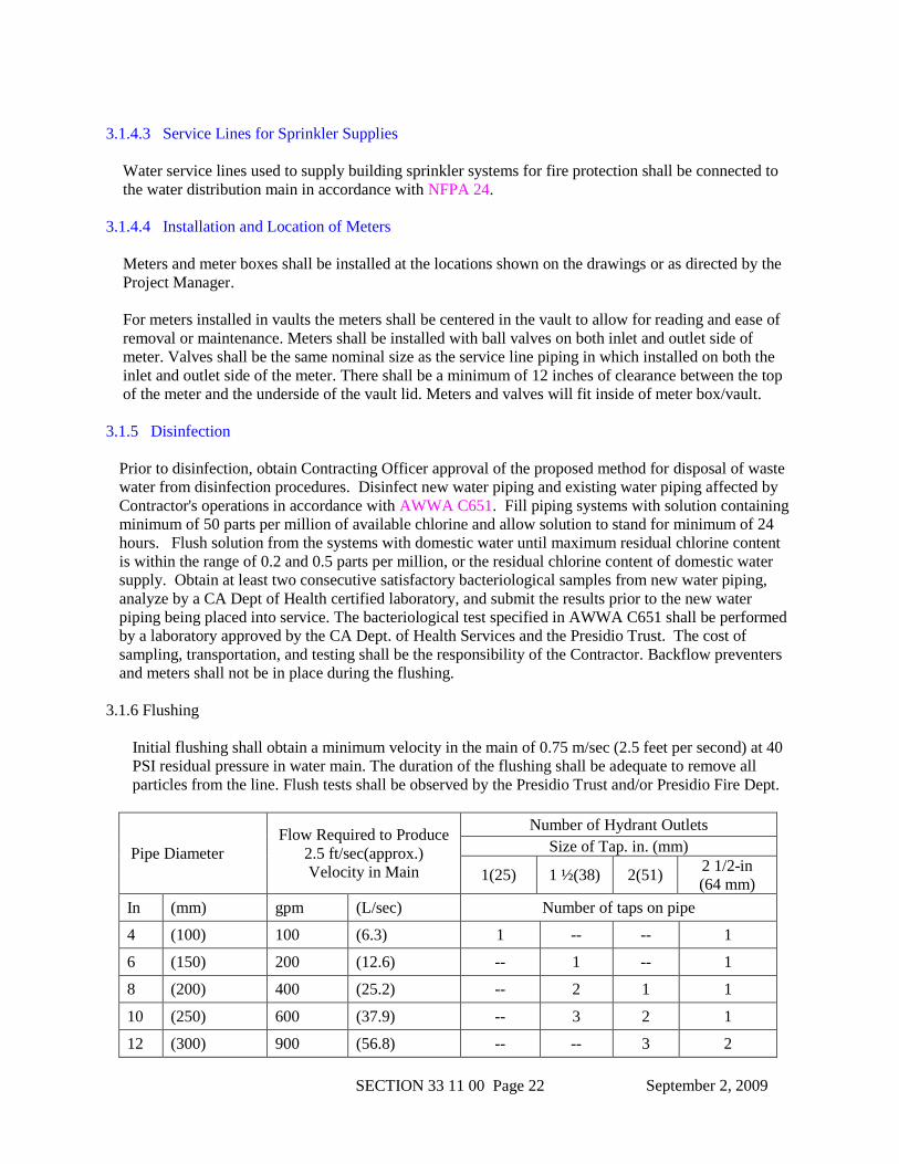
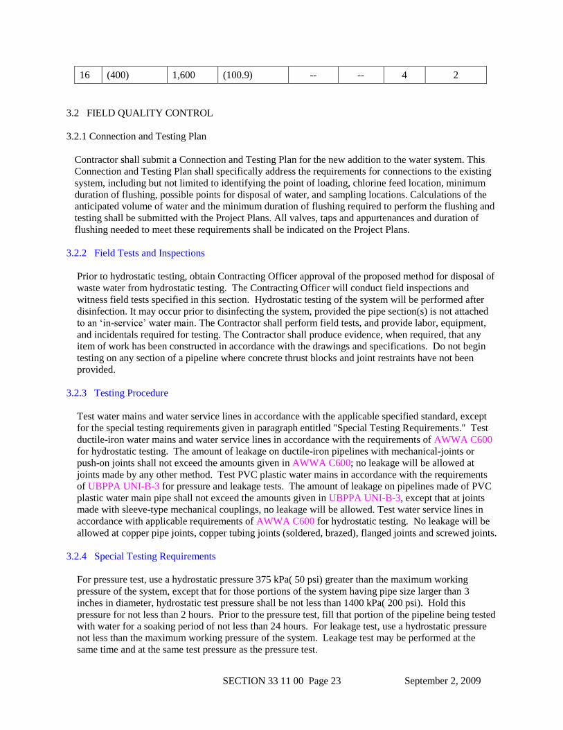
3.1.6 Flushing
Initial flushing shall obtain a minimum velocity in the main of 0.75 m/sec (2.5 feet per second) at 40
PSI residual pressure in water main. The duration of the flushing shall be adequate to remove all
particles from the line. Flush tests shall be observed by the Presidio Trust and/or Presidio Fire Dept.
Pipe Diameter
Flow Required to Produce
2.5 ft/sec(approx.)
Velocity in Main
Number of Hydrant Outlets
Size of Tap. in. (mm)
1(25) 1 ½(38) 2(51) 2 1/2-in
(64 mm)
In (mm) gpm (L/sec) Number of taps on pipe
4 (100) 100 (6.3) 1 -- -- 1
6 (150) 200 (12.6) -- 1 -- 1
8 (200) 400 (25.2) -- 2 1 1
10 (250) 600 (37.9) -- 3 2 1
12 (300) 900 (56.8) -- -- 3 2
September 2, 2009
SECTION 33 11 00 Page 23
16 (400) 1,600 (100.9) -- -- 4 2
3.2 FIELD QUALITY CONTROL
3.2.1 Connection and Testing Plan
Contractor shall submit a Connection and Testing Plan for the new addition to the water system. This
Connection and Testing Plan shall specifically address the requirements for connections to the existing
system, including but not limited to identifying the point of loading, chlorine feed location, minimum
duration of flushing, possible points for disposal of water, and sampling locations. Calculations of the
anticipated volume of water and the minimum duration of flushing required to perform the flushing and
testing shall be submitted with the Project Plans. All valves, taps and appurtenances and duration of
flushing needed to meet these requirements shall be indicated on the Project Plans.
3.2.2 Field Tests and Inspections
Prior to hydrostatic testing, obtain Contracting Officer approval of the proposed method for disposal of
waste water from hydrostatic testing. The Contracting Officer will conduct field inspections and
witness field tests specified in this section. Hydrostatic testing of the system will be performed after
disinfection. It may occur prior to disinfecting the system, provided the pipe section(s) is not attached
to an ‘in-service’ water main. The Contractor shall perform field tests, and provide labor, equipment,
and incidentals required for testing. The Contractor shall produce evidence, when required, that any
item of work has been constructed in accordance with the drawings and specifications. Do not begin
testing on any section of a pipeline where concrete thrust blocks and joint restraints have not been
provided.
3.2.3 Testing Procedure
Test water mains and water service lines in accordance with the applicable specified standard, except
for the special testing requirements given in paragraph entitled "Special Testing Requirements." Test
ductile-iron water mains and water service lines in accordance with the requirements of AWWA C600
for hydrostatic testing. The amount of leakage on ductile-iron pipelines with mechanical-joints or
push-on joints shall not exceed the amounts given in AWWA C600; no leakage will be allowed at
joints made by any other method. Test PVC plastic water mains in accordance with the requirements
of UBPPA UNI-B-3 for pressure and leakage tests. The amount of leakage on pipelines made of PVC
plastic water main pipe shall not exceed the amounts given in UBPPA UNI-B-3, except that at joints
made with sleeve-type mechanical couplings, no leakage will be allowed. Test water service lines in
accordance with applicable requirements of AWWA C600 for hydrostatic testing. No leakage will be
allowed at copper pipe joints, copper tubing joints (soldered, brazed), flanged joints and screwed joints.
3.2.4 Special Testing Requirements
For pressure test, use a hydrostatic pressure 375 kPa( 50 psi) greater than the maximum working
pressure of the system, except that for those portions of the system having pipe size larger than 3
inches in diameter, hydrostatic test pressure shall be not less than 1400 kPa( 200 psi). Hold this
pressure for not less than 2 hours. Prior to the pressure test, fill that portion of the pipeline being tested
with water for a soaking period of not less than 24 hours. For leakage test, use a hydrostatic pressure
not less than the maximum working pressure of the system. Leakage test may be performed at the
same time and at the same test pressure as the pressure test.
September 2, 2009
SECTION 33 11 00 Page 24
3.3 CLEANUP
Upon completion of the installation of water lines, and appurtenances, all debris and surplus materials
resulting from the work shall be removed.