Embed Size (px)
Citation preview

09-01-17
SECTION 33 63 00STEAM ENERGY DISTRIBUTION
SPEC WRITER NOTES:1. Delete between // // if not
applicable to project. Also delete any other item or paragraph not applicable in the Section and renumber the paragraphs.
2. References to pressure in this section are gauge pressure unless otherwise noted.
PART 1 - GENERAL1.1 DESCRIPTION
A. This section specifies materials and procedures for construction of
underground steam distribution and condensate return piping system,
including manholes, outside the buildings. System shall be: //walk
through concrete tunnels// //concrete shallow trenches// //pre-
engineered, direct-buried, drainable-dryable-testable (DDT)//.
B. A complete listing of common acronyms and abbreviations are included in
Section 23 05 10, COMMON WORK RESULTS FOR BOILER PLANT AND STEAM
GENERATION.
C. Definitions:
SPEC WRITER NOTE: Add definitions as necessary for project clarity.
1. System: The complete underground steam and condensate distribution
system including all components such as carrier piping, pipe
supports, insulation, protective enclosures, anchors, corrosion
protection, stress analysis, and accessories.
2. Pre-Engineered Direct-Buried System: A factory-fabricated system.
3. Drainable-Dryable-Testable (DDT) Pre-Engineered Direct-Buried System:
A factory-fabricated system.
4. Concrete Shallow Trench: A system with removable concrete cover in
sections located at grade.
5. Walk-through Concrete Tunnels: A system located below grade with
sufficient space for carrier pipes, other services, and space to walk
upright along the entire length of the system.
6. Carrier Pipe: Pipe carrying the steam or condensate.
1.2 RELATED WORKA. Section 01 00 00, GENERAL REQUIREMENTS.
B. Section 01 33 23, SHOP DRAWINGS, PRODUCT DATA AND SAMPLES.
33 63 00-1

09-01-17
C. Section 01 57 19, TEMPORARY ENVIRONMENTAL CONTROLS: Erosion and Sediment
Controls.
D. Section 01 74 19, CONSTRUCTION WASTE MANAGEMENT.
E. Section 01 81 13, SUSTAINABLE CONSTRUCTION REQUIREMENTS.
F. //Section 01 91 00, GENERAL COMMISSIONING REQUIREMENTS.//
G. SECTION 02 82 11, TRADITIONAL ASBESTOS ABATEMENT.
H. Section 03 30 00, CAST-IN-PLACE CONCRETE: Concrete Work, Reinforcing,
Placement and Finishing.
I. Section 05 50 00, METAL FABRICATIONS: Steel for trench and tunnel pipe
supports.
J. Section 09 91 00, PAINTING, Painting exposed steel and other surfaces.
K. //Section 13 05 41 SEISMIC RESTRAINT REQUIREMENTS FOR NON-STRUCTURAL
COMPONENTS: Bracing and concrete anchors.//
L. Section 23 05 10, COMMON WORK RESULTS FOR BOILER PLANT AND STEAM
GENERATION.
M. Section 25 10 10, ADVANCED UTILITY METERING SYSTEM: Metering.
N. Section 26 42 00, CATHODIC PROTECTION: Cathodic Protection of DDT Pre-
Engineered Direct-Buried Systems.
O. Section 31 20 00, EARTHWORK: Excavation, Trench Widths, Pipe Bedding,
Backfill, Shoring, Sheeting, Bracing.
P. //Section 33 08 00, COMMISSIONING OF SITE UTILITY SYSTEMS.//
1.3 APPLICABLE PUBLICATIONSSPEC WRITER NOTE: Make material requirements agree with requirements specified in the referenced Applicable Publications. Verify and update the publication list to that which applies to the project, unless the reference applies to all mechanical systems. Publications that apply to all mechanical systems may not be specifically referenced in the body of the specification, but, shall form a part of this specification.
A. The publications listed below form a part of this specification to the
extent referenced. The publications are referred in the text by the
basic designation only. Where conflicts occur these specifications and
the VHA standard will govern.
SPEC WRITER NOTE: Designer to investigate the appropriate AASHTO publication pertinent to load ratings of utilities beneath roads and include in this section.
33 63 00-2

09-01-17
B. American Association of State Highway and Transportation Officials
(AASHTO):
M300-03-UL-2007.........Standard Specification for Inorganic Zinc-Rich
Primer
M273-11-UL-2011.........Standard Specification for Precast Reinforced
Concrete Box Sections for Culverts, Storm
Drains, and Sewers with Less Than 2 Feet of
Cover Subjected to Highway Loadings
C. American Society of Heating, Refrigerating and Air-Conditioning
Engineers (ASHRAE):
90.1-2013...............Energy Efficient Design of New Buildings Except
Low-Rise Residential Buildings
D. American Society of Mechanical Engineers (ASME):
B1.20.1-2013............Pipe Threads, General Purpose (Inch)
B16.5-2013..............Pipe Flanges and Flanged Fittings: NPS 1/2
through NPS 24 Metric/Inch Standard
B16.9-2012..............Factory-Made Wrought Buttwelding Fittings
B16.11-2011.............Forged Fittings, Socket-Welding and Threaded
B16.21-2011.............Nonmetallic Flat Gaskets for Pipe Flanges
B18.2.1-2012............Square, Hex, Heavy Hex, and Askew Head Bolts and
Hex, Heavy Hex, Hex Flange, Lobed Head, and Lag
Screws (Inch Series)
B31.1-2014..............Power Piping
B31.9-2014..............Building Services Piping
B40.100-2013............Pressure Gauges and Gauge Attachments
ASME Boiler and Pressure Vessel Code -
BPVC Section VIII-1-2015 Rules for Construction of Pressure
Vessels, Division 1
BPVC Section IX-2015....Welding, Brazing, and Fusing Qualifications
E. American Society for Testing and Materials (ASTM):
A36/A36M-2014...........Standard Specification for Carbon Structural
Steel
A53/A53M-2012...........Standard Specification for Pipe, Steel, Black
and Hot-Dipped, Zinc-Coated, Welded and Seamless
A105/A105M-2014.........Standard Specification for Carbon Steel Forgings
for Piping Applications
A106/A106M-2015.........Standard Specification for Seamless Carbon Steel
Pipe for High-Temperature Service
33 63 00-3

09-01-17
A126-2004 (R2014).......Standard Specification for Gray Iron Castings
for Valves, Flanges, and Pipe Fittings
A139/A139M-2016.........Standard Specification for Electric-Fusion
(Arc)-Welded Steel Pipe (NPS 4 and Over)
A193/A193M-2016.........Standard Specification for Alloy-Steel and
Stainless-Steel Bolting for High Temperature or
High-Pressure Service and Other Special Purpose
Applications
A194/A194M-2015a........Standard Specification for Carbon Steel, Alloy
Steel, and Stainless-Steel Nuts for Bolts for
High Pressure or High Temperature Service, or
Both
A234/A234M-2015.........Standard Specification for Piping Fittings of
Wrought Carbon Steel and Alloy Steel for
Moderate and High Temperature Service
A240/A240M-2015b........Standard Specification for Chromium and
Chromium-Nickel Stainless Steel Plate, Sheet,
and Strip for Pressure Vessels and for General
Applications
A733-2015...............Standard Specification for Welded and Seamless
Carbon Steel and Austenitic Stainless-Steel Pipe
Nipples
B61-2015................Standard Specification for Steam or Valve Bronze
Castings
C177-2013...............Standard Test Method for Steady-State Heat Flux
Measurements and Thermal Transmission Properties
by Means of the Guarded-Hot-Plate Apparatus
C411-05.................Standard Test Method for Hot-Surface Performance
of High-Temperature Thermal Insulation
C552-07.................Cellular Glass Thermal Insulation
C655-2015...............Standard Specification for Reinforced Concrete
D-Load Culvert, Storm Drain, and Sewer Pipe
C920-2014a..............Standard Specification for Elastomeric Joint
Sealants
C1728-2013..............Standard Specification for Flexible Aerogel
Insulation
E84-2015b...............Standard Test Method for Surface Burning
Characteristics of Building Materials
33 63 00-4

09-01-17
F. American Welding Society (AWS):
B2.1/B2.1M-2014.........Specification for Welding Procedure and
Performance Qualification
D10.12M/D10.12-2000.....Guide for Welding Mild Steel Pipe
Z49.1-2012..............Safety in Welding and Cutting and Allied
Processes
G. Federal Specifications (Fed. Spec.):
A-A-60005-2015..........Frames, Covers, Gratings, Steps, Sump and Catch
Basin, Manhole
L-S-125-1987............Screening, Insect, Nonmetallic
H. Manufacturer’s Standardization Society (MSS):
MSS SP-58-2009..........Pipe Hangers and Supports - Materials, Design,
Manufacture, Selection, Application and
Installation
I. Military Specifications (Mil. Spec.):
MIL-S-901-1989..........Shock Tests H.I. (High Impact) Shipboard
Machinery, Equipment and Systems, Requirements
for
J. NACE International (NACE):
SP0169-2013.............Control of External Corrosion on Underground or
Submerged Metallic Piping Systems
K. National Fire Protection Association (NFPA):
255-2006................Standard Method of Test of Surface Burning
Characteristics of Building Materials
L. Society for Protective Coatings (SSPC):
SP-2-2004...............Hand Tool Cleaning
1.4 SUBMITTALSA. Submittals, including number of required copies, shall be submitted in
accordance with Section 01 33 23, SHOP DRAWINGS, PRODUCT DATA, and
SAMPLES.
B. Information and material submitted under this section shall be marked
"SUBMITTED UNDER SECTION 33 63 00, STEAM ENERGY DISTRIBUTION”, with
applicable paragraph identification.
C. Contractor shall make all necessary field measurements and
investigations to assure that the equipment and assemblies will meet
contract requirements and will fit the space available.
D. If equipment is submitted which differs in arrangement from that shown,
provide drawings that show the rearrangement of all associated systems.
33 63 00-5
09-01-17
Approval will be given only if all features of the equipment and
associated systems, including accessibility, are equivalent to that
required by the contract.
E. Prior to submitting shop drawings for approval, contractor shall certify
in writing that manufacturers of all major items of equipment have each
reviewed drawings and specifications, and have jointly coordinated and
properly integrated their equipment and controls to provide a complete
and efficient installation.
F. Installing Contractor shall provide lists of previous installations for
selected items of equipment. Contact persons who will serve as
references, with telephone numbers and e-mail addresses shall be
submitted with the references. COMMON WORK RESULTS FOR PLUMBING", with
applicable paragraph identification.
G. Manufacturers’ Literature and Data including: Full item description and
optional features and accessories of the complete system including, but
not limited to, dimensions, weights, materials, applications, standard
compliance, model numbers, size and capacity. Submit as one package for
pipes, fittings and appurtenances, including jointing materials,
insulation, hangars, expansion and power set fasteners, and other
miscellaneous items.
H. Submittals and shop drawings for interdependent items, containing
applicable descriptive information, shall be furnished together and
complete in a group. Coordinate and properly integrate materials and
equipment in each group to provide a completely compatible and efficient
installation. Final review and approvals will be made only by groups.
I. Coordination/Shop Drawings:
1. Submit complete consolidated and coordinated shop drawings for all
new systems, and for existing systems that are in the same areas.
2. The coordination/shop drawings shall include plan views, elevations
and sections of all systems and shall be on a scale of not less than
1:32 (3/8 inch equal to one foot). Clearly identify and dimension the
proposed locations of the principal items of equipment. The drawings
shall clearly show the proposed locations and adequate clearance for
all equipment, controls, piping, pumps, valves and other items. All
equipment requiring service shall be provided with an access door
sized for the complete removal of device, component, or servicing of
the equipment. Access for service and access for removal of
components may be separate as necessary. Provide detailed
33 63 00-6
09-01-17
coordination/shop drawings and loading calculations for all piping
systems. The drawings should include all lockout/tagout points for
all energy/hazard sources for each piece of equipment. Coordinate
lockout/tagout procedures and practices with local VA requirements.
3. Do not install equipment foundations, equipment or piping until
coordination/shop drawings have been approved.
J. Complete operating and maintenance manuals including wiring diagrams,
technical data sheets, information for ordering replacement parts, and
troubleshooting guide:
1. Include complete list indicating all components of the systems.
2. Include complete diagrams of the internal wiring for each item of
equipment.
3. Diagrams shall have their terminals identified to facilitate
installation, operation and maintenance.
K. //Completed System Readiness Checklist provided by the Commissioning
Agent and completed by the contractor, signed by a qualified technician
and dated on the date of completion, in accordance with the requirements
of Section 33 08 00, COMMISSIONING OF SITE UTILITY SYSTEMS. This shall
include pressure testing and cleaning of piping systems.//
L. //Submit training plans and instructor qualifications in accordance with
the requirements of Section 33 08 00, COMMISSIONING OF SITE UTILITY
SYSTEMS.//
1.5 QUALITY ASSURANCEA. Products Criteria:
1. Standard Products: Material and equipment shall be the standard
products of a manufacturer regularly engaged in the manufacture,
supply and servicing of the specified products for at least 5 years.
However, digital electronics devices, software and systems such as
controls and instruments, shall be the current generation of
technology and basic design that has a proven satisfactory service
record of at least 5 years.
2. All items furnished shall be free from defects that would adversely
affect the performance, maintainability and appearance of individual
components and overall assembly.
3. The products and execution of work specified in Division 33 shall
conform to the referenced codes and standards as required by the
specifications. Local codes and amendments shall be enforced, along
with requirements of local utility companies. The most stringent
33 63 00-7
09-01-17
requirements of these specifications, local codes, or utility company
requirements shall always apply. Any conflicts shall be brought to
the attention of the COR.
4. When two or more units of the same type or class of materials or
equipment are required, these units shall be products of one
manufacturer.
5. Assembled Units: Manufacturers of equipment assemblies, which use
components made by others, assume complete responsibility for the
final assembled product.
6. A nameplate bearing manufacturer's name or trademark, including model
number, shall be securely affixed in a conspicuous place on
equipment. In addition, the model number shall be cast integrally
with equipment, stamped, or otherwise permanently marked on each item
of equipment.
7. Asbestos products or equipment or materials containing asbestos shall
not be used.
B. Contractor shall restore damaged items to as-new operating condition or
replace damaged items as directed by the COR, at no additional cost or
time to the Government.
C. Welding Qualifications: Before any welding is performed, contractor
shall submit a certificate certifying that welders comply with the
following requirements:
1. Qualify welding processes and operators for piping according to ASME
BPVC Section IX, AWS Z49.1 and AWS B2.1/B2.1M.
2. Comply with provisions in //ASME B31.9// //ASME B31.1//.
3. Certify that each welder and welding operator has passed AWS
qualification tests for welding processes involved and that
certification is current and recent. Submit documentation to the COR.
4. All welds shall be stamped according to the provisions of the
American Welding Society.
D. ASME Compliance: Comply with //ASME B31.9// //ASME B31.1// for
materials, products, and installation. Safety valves and pressure
vessels shall bear appropriate ASME labels.
1.6 DELIVERY, STORAGE AND HANDLINGA. Equipment and material placed on the job site shall remain in the
custody of the Contractor until phased acceptance, whether or not the
Government has reimbursed the Contractor for the equipment and material.
33 63 00-8
09-01-17
The Contractor is solely responsible for the protection of equipment and
material against damage or theft.
B. Protect piping systems against the entry of water, mud or other foreign
substances by installing watertight covers on open ends at all times.
Both inside and outside shall be cleaned before painting or placing
equipment in operation. Protect direct-buried system coatings from
ultraviolet light (sunlight). Existing equipment worked on by the
Contractor or in the Contractor's working area shall be considered to be
in the custody and responsibility of the Contractor and shall be
protected as required for new work.
C. Damaged equipment shall be replaced with an identical unit as determined
and directed by the COR. All insulated piping systems exposed to water
must be replaced prior to installation at no additional cost or time to
the Government.
1.7 AS-BUILT DOCUMENTATIONSPEC WRITER NOTE: Coordinate O&M Manual requirements with Section 01 00 00, GENERAL REQUIREMENTS. O&M manuals shall be submitted for content review as part of the close-out documents.
A. Submit manufacturer’s literature and data updated to include submittal
review comments and any equipment substitutions.
B. Submit operation and maintenance data updated to include submittal
review comments, VA approved substitutions and construction revisions
shall be //in electronic version on CD or DVD// inserted into a three-
ring binder. All aspects of system operation and maintenance procedures,
including applicable piping isometrics, wiring diagrams of all circuits,
a written description of system design, control logic, and sequence of
operation shall be included in the operation and maintenance manual. The
operations and maintenance manual shall include troubleshooting
techniques and procedures for emergency situations. Notes on all special
systems or devices shall be included. A list of recommended spare parts
(manufacturer, model number, and quantity) shall be furnished.
Information explaining any special knowledge or tools the owner will be
required to employ shall be inserted into the As-Built documentation.
SPEC WRITER NOTE: Select and edit one of the bracketed options after the paragraph below to indicate the format in which the contractor must provide record drawing files. Select the hand-marked option only when the designer has been separately
33 63 00-9
09-01-17
contracted to provide the record drawings from the contractor’s mark-ups. Select the BIM option only when a BIM model will be generated, which is typically only performed by the designer on some Design-Bid-Build projects or by the contractor on some Design-Build projects.
C. The installing contractor shall maintain as-built drawings of each
completed phase for verification; and, shall provide the complete set at
the time of final systems certification testing. Should the installing
contractor engage the testing company to provide as-built or any portion
thereof, it shall not be deemed a conflict of interest or breach of the
‘third party testing company’ requirement. Provide record drawings as
follows:
1. //Red-lined, hand-marked drawings are to be provided, with one paper
copy and a scanned PDF version of the hand-marked drawings provided
on CD or DVD.//
2. //As-built drawings are to be provided, with a copy of them on
AutoCAD version // // provided on CD or DVD. The CAD drawings shall
use multiple line layers with a separate individual layer for each
system.//
3. //As-built drawings are to be provided, with a copy of them in three-
dimensional Building Information Modeling (BIM) software version //
// provided on CD or DVD.//
D. The as-built drawings shall indicate the location and type of all
lockout/tagout points for all energy sources for all equipment and pumps
to include breaker location and numbers, valve tag numbers, etc.
Coordinate lockout/tagout procedures and practices with local VA
requirements.
E. Certification documentation shall be provided to COR 21 working days
prior to submitting the request for final inspection. The documentation
shall include all test results, the names of individuals performing work
for the testing agency on this project, detailed procedures followed for
all tests, and provide documentation/certification that all results of
tests were within limits specified. Test results shall contain written
sequence of test procedure with written test results annotated at each
step along with the expected outcome or setpoint. The results shall
include all readings, including but not limited to data on device (make,
model and performance characteristics), normal pressures, switch ranges,
33 63 00-10

09-01-17
trip points, amp readings, and calibration data to include equipment
serial numbers or individual identifications, etc.
1.8 COORDINATIONA. Coordinate exterior steam lines and associated systems and connections
to building services up to the actual extent of building wall.
1.9 UTILITY LOCATION SERVICESA. Prior to any demolition //or excavation//, provide for utility location
services to mark on the ground with fluorescent paint the location of
existing underground utilities, and their identification. The term
“utility(ies)” includes both public utilities and VA-owned utilities,
for all underground services.
PART 2 - PRODUCTS2.1 STEEL PIPES AND FITTINGS
SPEC WRITER NOTE: Retain this article for direct-bury piping or to describe materials for carrier pipe for cased piping.
A. Steel Pipe: ASTM A53/A53M, Type E, Grade A, black with plain ends.
B. Forged Steel Flanges and Flanged Fittings: ASME B16.5, including bolts,
nuts, and gaskets of the following material group, end connections, and
facings:
1. Material Group: 1.1.
2. End Connections: Butt welding.
3. Facings: Raised face.
C. Steel Welding Fittings: //ASME B16.9// //ASTM A234/A234M//, seamless or
welded.
1. Welding Filler Metals shall comply with AWS D10.12M/D10.12 for
welding materials appropriate for wall thickness and chemical
analysis of steel pipe being welded.
D. Nipples: ASTM A733, Standard Weight, seamless, carbon-steel pipe.
E. Pipe-Flange Gasket Materials: ASME B16.21, suitable for chemical and
thermal conditions of piping system contents, nonmetallic, flat,
asbestos free, 3.2 mm (1/8 inch) maximum thickness unless thickness or
specific material is indicated.
1. For flat-face, Class 125 flanges.
2. For raised-face, Class 250 steel flanges.
F. Flange Bolts and Nuts: ASME B18.2.1, carbon steel, unless otherwise
indicated.
33 63 00-11
09-01-17
2.2 PRE-ENGINEERED, FACTORY-FABRICATED, DIRECT-BUIRED, DRAINABLE-DRYABLE-TESTABLE (DDT) SYSTEMS
SPEC WRITER NOTES:1. Increase the pressures and temperatures
listed below as necessary to suit the project.
2. This type of system is allowed in Class A, B, C, D site conditions as defined in Appendix II.
3. Site classifications depend on the groundwater table as per geotechnical report.
4. The VA prefers piping inside tunnels instead of direct-buried piping, unless there is a compelling reason to go with direct-buried system and justified with Life Cycle Cost analysis.
A. Complete factory-fabricated steam and condensate piping system with
carrier pipes, carrier pipe insulation with jackets and banding, air
space, 6 mm (1/4 inch) thick steel casing, fusion-bonded epoxy casing
coatings, cathodic protection, accessories. Do not locate condensate
pipes in casings that contain steam pipes.
B. All components of system shall be suitable for carrier pipe pressures
and temperatures as follows:
1. Steam System: 1035 kPa (150 psig); 185 degrees C (366 degrees F).
2. Condensate System: 345 kPa (50 psig); 154 degrees C (310 degrees F).
C. Steam Carrier Pipes and Condensate Carrier Pipes: No piping joints are
allowed in factory-fabricated straight sections of pre-engineered
direct-buried systems.
D. Carrier Pipe Insulation:
1. Conform to minimum thickness and type of insulation listed in Tables
1 and 2 below as required for service temperature in carrier pipe as
listed below.
SPEC WRITER NOTE: Label pipe Sections A, B, etc. on the drawings to identify the locations of various steam temperatures (pressures).
2. Section A: Steam temperature is // _____degrees C (_____ degrees F),
steam pressure is ____ kPa (psig)//. Pumped condensate temperature is
93 degrees C (200 degrees F). Drip return temperature is 100 degrees
C (212 degrees F).
3. Section B: Steam temperature is // _____degrees C (_____degrees F),
steam pressure is ____ kPa (psig)//. Pumped condensate temperature is
33 63 00-12
09-01-17
93 degrees C (200 degrees F). Drip return temperature is 100 degrees
C (212 degrees F).
4. Allowable Carrier Pipe Insulation Type and Minimum Insulation
Thickness:
TABLE 1Minimum Pipe Insulation Thickness mm (inches)
For Steam 110 to 2800 kPa (16 to 406 psig) gauge
Nominal Pipe Diameter mm (inches)
Pre-Formed Mineral Wool Calcium Silicate
25 (1) 65 (2-1/2) 100 (4)
40 (1-1/2) 65 (2-1/2) 100 (4)
50 (2) 90 (3-1/2) 115 (4-1/2)
65 (2-1/2) 90 (3-1/2) 115 (4-1/2)
75 (3) 100 (4) 125 (5)
100 (4) 100 (4) 125 (5)
125 (5) 100 (4) 125 (5)
150 (6) 115 (4-1/2) 140 (5-1/2)
200 (8) 115 (4-1/2) 140 (5-1/2)
250 (10) 125 (5) 150 (6)
300 (12) 125 (5) 150 (6)
355 (14) 125 (5) 150 (6)
406 (16) 125 (5) 150 (6)
457 (18) 125 (5) 150 (6)
Notes:
1. Submittals shall include manufacturer’s certification that all
insulation have passed the 96-hour boiling water test.
2. Pipes smaller than 25 mm (1 inch) shall have same insulation
thickness as required for 25 mm (1 inch) pipe.
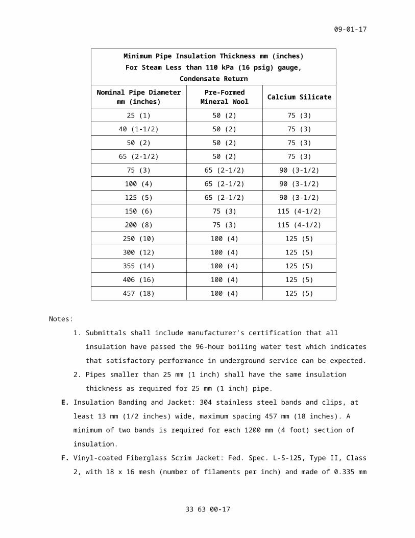
TABLE 2Minimum Pipe Insulation Thickness mm (inches)For Steam Less than 110 kPa (16 psig) gauge,
Condensate Return
Nominal Pipe Diameter mm (inches)
Pre-Formed Mineral Wool Calcium Silicate
25 (1) 50 (2) 75 (3)
40 (1-1/2) 50 (2) 75 (3)
50 (2) 50 (2) 75 (3)
33 63 00-13

09-01-17
65 (2-1/2) 50 (2) 75 (3)
75 (3) 65 (2-1/2) 90 (3-1/2)
100 (4) 65 (2-1/2) 90 (3-1/2)
125 (5) 65 (2-1/2) 90 (3-1/2)
150 (6) 75 (3) 115 (4-1/2)
200 (8) 75 (3) 115 (4-1/2)
250 (10) 100 (4) 125 (5)
300 (12) 100 (4) 125 (5)
355 (14) 100 (4) 125 (5)
406 (16) 100 (4) 125 (5)
457 (18) 100 (4) 125 (5)
Notes:
1. Submittals shall include manufacturer’s certification that all
insulation have passed the 96-hour boiling water test which indicates
that satisfactory performance in underground service can be expected.
2. Pipes smaller than 25 mm (1 inch) shall have the same insulation
thickness as required for 25 mm (1 inch) pipe.
E. Insulation Banding and Jacket: 304 stainless steel bands and clips, at
least 13 mm (1/2 inches) wide, maximum spacing 457 mm (18 inches). A
minimum of two bands is required for each 1200 mm (4 foot) section of
insulation.
F. Vinyl-coated Fiberglass Scrim Jacket: Fed. Spec. L-S-125, Type II, Class
2, with 18 x 16 mesh (number of filaments per inch) and made of 0.335 mm
(0.013 inch) diameter vinyl-coated fibrous glass yarn. Install bands
over the jacket to secure the insulation to the carrier pipe.
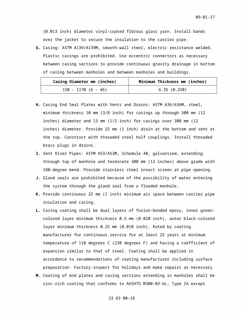
G. Casing: ASTM A139/A139M, smooth-wall steel, electric resistance welded.
Plastic casings are prohibited. Use eccentric connectors as necessary
between casing sections to provide continuous gravity drainage in bottom
of casing between manholes and between manholes and buildings.
Casing Diameter mm (inches) Minimum Thickness mm (inches)
150 - 1170 (6 – 46) 6.35 (0.250)
H. Casing End Seal Plates with Vents and Drains: ASTM A36/A36M, steel,
minimum thickness 10 mm (3/8 inch) for casings up through 300 mm (12
inches) diameter and 13 mm (1/2 inch) for casings over 300 mm (12
inches) diameter. Provide 25 mm (1 inch) drain at the bottom and vent at
33 63 00-14
09-01-17
the top. Construct with threaded steel half couplings. Install threaded
brass plugs in drains.
I. Vent Riser Pipes: ASTM A53/A53M, Schedule 40, galvanized, extending
through top of manhole and terminate 300 mm (12 inches) above grade with
180-degree bend. Provide stainless steel insect screen at pipe opening.
J. Gland seals are prohibited because of the possibility of water entering
the system through the gland seal from a flooded manhole.
K. Provide continuous 25 mm (1 inch) minimum air space between carrier pipe
insulation and casing.
L. Casing coating shall be dual layers of fusion-bonded epoxy, inner green-
colored layer minimum thickness 0.5 mm (0.020 inch), outer black-colored
layer minimum thickness 0.25 mm (0.010 inch). Rated by coating
manufacturer for continuous service for at least 25 years at minimum
temperature of 110 degrees C (230 degrees F) and having a coefficient of
expansion similar to that of steel. Coating shall be applied in
accordance to recommendations of coating manufacturer including surface
preparation. Factory-inspect for holidays and make repairs as necessary.
M. Coating of end plates and casing sections extending in manholes shall be
zinc-rich coating that conforms to AASHTO M300-03-UL, Type IA except
that volatile organic compounds shall not exceed 0.34 kg per liter (2.8
pounds per gallon). The zinc rich coating shall be applied in accordance
with the recommendations of the coating manufacturer including surface
preparation. No additional top coat shall be applied.
N. Carrier pipe guides and supports shall be maximum spacing 3000 mm (10
feet) on centers, no greater than 1500 mm (5 feet) from pipe ends,
minimum of three guides per elbow section. Designed to permit thermal
expansion without damage, provide proper pipe guiding and support, and
to allow horizontal movement in two directions as necessary at expansion
loops and bends. Design of guides and supports must permit continuous
drainage of water in bottom of casing. Pipe insulation shall extend
through the pipe guides and supports and be protected by steel sleeves.
Design of guides and supports shall be such that no metal-to-metal
contact exists between the casing and the carrier pipe. Insulation or
non-metallic material used to ensure no metal to metal contact shall be
designed to not be compressed by the weight of the carrier pipe when
full of water.
O. Anchor plates shall be ASTM A36/A36M steel, welded to carrier pipe and
casing, 15 mm (1/2 inch) minimum thickness, passages for air flow and
33 63 00-15

09-01-17
water drainage through the annular air space in the system. Coated with
same coating material as the casing. Locate 900 to 1500 mm (3 to 5 feet)
from piping entrance to manhole or building wall. Walls of manholes and
buildings cannot be utilized as anchor points.
P. Field connection of casing sections shall be steel section conforming to
casing specification, welded to casing sections, coated on all surfaces
with system manufacturer’s coating field repair compound, and covered
with a 1.3 mm (0.05 inch) minimum thickness polyethylene shrink sleeve
designed for a service temperature exceeding 80 degrees C (176 degrees
F).
Q. Manhole and building wall penetrations shall provide steel leak plates
welded to wall sleeves or to casings. Where a wall sleeve is utilized,
allow sufficient annular space between the sleeve and the casing and
install a watertight seal, rated for 121 degrees C (250 degrees F)
minimum. Manhole and building walls cannot be used as anchor points.
R. Provide sacrificial anode type cathodic protection system with
dielectric isolation devices and test stations for all systems. Design
system for 25 years of service, assume two percent bare metal. System
shall comply with NACE SP0169.
S. Provide embossed brass or stainless-steel tag hung by a brass or
stainless-steel chain at each end of each casing or insulated piping in
the manholes and buildings. The tag shall identify system manufacturer’s
name, date of installation, government contract, and manufacturer’s
project number.
T. All branch piping connections must be located in manholes.
SPEC WRITER NOTE: In all cases and subject to VAMC management approval, the manholes need to reduce confined space access requirements. This includes easy access, and may include open or semi-open tops.
U. Ensure the DDT manufacturer is responsible for the complete design of
the DDT system, including, but not limited to, the product to be
supplied, fabrication, installation, supervision, and testing of the
system within the design parameters established by the contract
documents, and in compliance with the detailed design. The complete
design of the system shall be sealed by a Professional Engineer in the
employ of the DDT manufacturer.
V. Furnish thermal expansion calculations for the steam and condensate
piping using the design characteristics indicated in this section and
33 63 00-16
09-01-17
installation temperature no higher than the ambient temperature at the
site: // // degrees C (// // degrees F).
W. DDT manufacturer shall submit a complete description of the design and
assembly of the system, materials of construction and field installation
instructions. Include sufficient system details to show that the
specified minimum insulation thickness has been met. A detailed design
layout of the system (plan and elevation views) showing size, type,
elevations and location of each component to be used in the system, the
design and location of anchors, pipe guides, pipe supports, expansion
loops, Z-bends, L-bends, end seals, leak plates, joint locations, pipe
and insulation thickness and sizes, types, and movements, connection to
manhole and building wall penetrations, and including, if applicable,
details of transition point to aboveground or other type systems.
Detailed design layout drawings shall be stamped by a registered
Professional Engineer.
X. Expansion Loops and Bends: Pipe-stress and system-expansion calculations
for each expansion compensation elbow using a finite element computer
generated 3-dimensional analysis (FEA). Demonstrate with calculations
that pipe stresses from temperature changes are within the allowable
requirements in ASME B31.1 and that the anchors and the guides will
withstand the resultant forces. Detailed design layout drawings shall
include all analysis node points. As a minimum, computer analysis
results shall include node stresses, forces, moments and displacements.
Calculations shall be stamped by a registered Professional Engineer in
the employ of the DDT manufacturer.
Y. Reinforced Concrete Manholes: Not less than 200 mm (8 inches) thick.
Pour monolithically where possible. Place waterproof membrane between
mud slab and bottom concrete slab, and continue up sides to top of
sidewalls. Joints between manhole walls and casings or concrete trench
sections shall be watertight. Steel manholes or prefabricated concrete
manholes are prohibited.
Z. Accessories for Manholes: Cast iron manhole frames and solid covers, not
less than 711 mm (28 inches) clear openings. Unless otherwise shown on
the drawings, frames and covers shall be as follows:
1. For non-traffic applications:
a. Fed. Spec. A-A-60005 NOT1, Frame Type IV, Size 28
b. Fed. Spec. A-A-60005 NOT1, Cover Type E, Size 28, cast
identification “STEAM”.
33 63 00-17
09-01-17
2. For traffic applications:
a. Fed. Spec. A-A-60005 NOT1, Frame Type I, Style A, Size 27A.
b. Fed. Spec. A-A-60005 NOT1, Cover Type A, Size 27A, cast
identification “STEAM”.
3. Manhole steps shall be standard, cast iron.
AA. Manhole Ventilation: As indicated on Drawings. Construct
ventilation ducts of galvanized steel sheet metal and in accordance with
ASHRAE Handbook recommendations for low pressure ducts. Gravity
ventilators shall be factory-fabricated of aluminum or galvanized steel
and arranged as indicated on drawings. Ventilating pipes shall be
standard weight black steel and installed as shown on drawings.
BB. Drainage as shown on drawings. Provide a 600 mm (24 inches) square
by 600 mm (24 inches) deep sump pit in each manhole where indicated on
drawings. Provide larger sump pit if necessary to accommodate required
electric sump pumps.
CC. Electric Sump Pumps with Automatic Controls and High-Water Alarm:
1. Type: High temperature submersible duplex pumps and automatic
controls.
2. Service: Continuous operation at required flows and pressures while
completely submerged at 93 degrees C (200 degrees F). All pumps and
pump controls shall have demonstrated 200,000 cycles of operation
while totally submerged in 93 degrees C (200 degrees F) water.
3. Capacity and Pressure: Pumps shall be capable of passing 10 mm (3/8
inch) spheres.
4. Pumps: Epoxy-coated cast iron casing, cast iron impeller, stainless
steel shaft, carbon/ceramic shaft seal, stainless steel hardware,
permanently lubricated bearings, screened inlets. Schedule 80
discharge pipe protected from corrosion.
5. Motors: Non-overloading at all points on the pump performance curve.
Include overload protection.
6. Controls: Automatic alternating lead-lag, with damp-proof electrical
service. Mount non-submerged control components in a NEMA 4 enclosure
on adjacent wall or dedicated galvanized steel support stand.
7. High Water Alarm Switch: Set at level below lowest steam or
condensate pipe in the manhole. Switch shall activate weatherproof
red alarm light mounted above grade as shown. Provide contacts //and
connect to// //for future connection// to engineering control center.
33 63 00-18
09-01-17
2.3 TUNNELS (WALK THROUGH)SPEC WRITER NOTE: Use A or B, or combination of both. If both are used, show locations on Drawings. This Section does not adequately address paths and clearances, lighting, drainage, and ventilation systems. These things require design by other disciplines, and require the contractor's work to be depicted on drawings. The VA general intent is that: (a) the designer avoids causing a space that would be categorized as "Confined Space - Permit Entry" whenever possible, and (b) the designer avoids pumps and design drainage systems that drain by gravity whenever possible.
A. Reinforced Concrete Tunnel: Place waterproof membrane between mud slab
and bottom concrete slab and continue up sides and over top of tunnel
roof slab.
B. Precast Concrete Tunnel: ASTM C655. Construct precast concrete pipe
tunnel with straight runs of tunnel. Provide cast-in-place concrete
tunnel sections at each bend and at each change in grade of the tunnel.
Mortar shall be as recommended by the precast concrete tunnel
manufacturer.
C. Ventilation Ducts: Galvanized sheet steel constructed in accordance with
ASHRAE Handbook recommendations. Gravity ventilators shall be factory-
fabricated of aluminum or galvanized steel.
D. Provide drainage system at all low points of tunnel systems as shown on
the drawings.
E. Waterproof manholes and below grade ventilation ducts.
2.4 CONCRETE SHALLOW TRENCHESA. Cast-in-Place Trench: Reinforced concrete with minimum thickness 200 mm
(8 inches).
1. Trench Covers in Grass or Sidewalk Areas: Precast reinforced concrete
sections, set to existing grade, flat and true at all points of
contact on trench wall; trench and cover to form a watertight
envelope when assembled.
2. Trench Covers in Pavement: Precast reinforced concrete sections per
AASHTO M273-11-UL, set to existing pavement, flat and true at all
points of contact on trench wall; trench and cover to form a
watertight envelope when assembled.
3. Waterproofing: Apply to all below grade portions of the trench.
33 63 00-19

09-01-17
4. Gaskets and Sealants: ASTM C920, 6 mm (1/4 inch) thick neoprene pads
with a minimum width of 50 mm (2 inches) between covers and tops of
walls; elastomeric sealants that are available as a one or two
component system. Asphaltic sealants are prohibited. Sealants must
resist 50 percent total joint movement. Non-sagging sealant must be
used for vertical joints. Self-leveling sealant must be used for
trench top butt joints.
2.5 STEAM PIPINGA. Pipe: //ASTM A53/A53M, steel, seamless, Grade B// //ASTM A106/A106M,
Grade B, electric resistance welded//, //Schedule 40// //Schedule 80//.
Grade F, furnace butt-welded pipe is prohibited. Use Schedule 80 pipe
and fittings for threaded joints.
B. Joints:
1. In trenches: Butt-weld joints. Socket weld is required for pipe sizes
50 mm (2 inches) and less.
2. In tunnels, manholes, and open areas: Butt weld pipe sizes 65 mm (2-
1/2 inches) and greater; thread or socket weld pipe sized 50 mm (2
inches) and less. Use Schedule 80 pipe and fittings for threaded
joints.
C. Fittings:
1. Butt welded joints: ASTM A234/A234M or ASME B16.9, steel, Grade B,
same schedule as adjoining pipe. All elbows shall be long radius
unless otherwise indicated. Tees shall be full size or reducing as
required, having interior surfaces smoothly contoured.
2. Threaded joints: ASME B16.11, forged steel fittings, Class 2000. Use
Schedule 80 pipe only.
3. Socket welded joints: ASME B16.11, forged steel, 13,800 kPa (2000
psig) class.
D. Flanges and Bolts: //ASME B16.5, weld neck, forged steel// //ASTM
A105/A105M, pressure class 1035 kPa (150 psig)//. Bolts shall be high
strength ASTM A193/A193M, Class 2, Grade B7. Nuts shall be ASTM
A194/A194M.
E. Unions: Pipe 50 mm (2 inches) and less shall be threaded, steel, 2050
kPa (297 psig) class.
2.6 STEAM CONDENSATE PIPINGA. Pipe: //ASTM A53/A53M, seamless, Grade B// //ASTM A106/A106M, Grade
B// //ASTM A53/A53M electric resistance welded, Grade B//, Schedule 80.
33 63 00-20
09-01-17
Grade F, furnace butt-welded pipe is prohibited. Use Schedule 80 pipe
and fittings for threaded joints.
B. Joints:
1. In trenches: Butt weld joints. Socket weld is required for pipe sizes
50 mm (2 inches) and less.
2. In tunnels, manholes, and open areas: Butt weld pipe sizes 65 mm (2-
1/2 inches) and greater. For system pressures of 103 kPa (15 psi) or
less, thread or socket weld pipe sizes 50 mm (2 inches) and less. For
system pressures of 103 kPa (15 psi) and no greater than 700 kPa (100
psig), socket weld pipe sizes 25 mm (1 inch) and greater, and thread
pipe sizes less than 25 mm (1 inch). For higher system pressure,
socket weld pipe sizes of 50 mm (2 inches) or less.
C. Fittings:
1. Welded joints: ASTM A234/A234M, steel, Grade B, or ASME B16.9, same
schedule as adjoining pipe.
2. Threaded joints: ASME B16.11, forged steel fittings, Class 2000. Use
Schedule 80 pipe and fittings only.
3. Socket welded joints: ASME B16.11, forged steel, 13,800 kPa (2000
psig) class.
D. Unions (Except in Trenches): Pipe 50 mm (2 inches) and less, 2050 kPa
(297 psig) steel.
E. Flanges: Weld neck ASME B16.5 or ASTM A105/A105M, forged steel, 1035 kPa
(150 psig).
SPEC WRITER NOTE: Increase pressures and temperatures listed below if necessary to suit project conditions.
2.7 EXPANSION LOOPS AND BENDSA. Stresses: Less than the maximum allowable stress in accordance with ASME
B31.1. Submit shop drawings and stress and anchor force calculations for
all loops and bends. Show locations of all anchors, guides and supports.
Base calculations on 1035 kPa (150 psig) and 185 degrees C (366 degrees
F) for steam line loops and bends and 345 kPa (50 psig) and 154 degrees
C (310 degrees F) for condensate return line loops and bends. Base
calculations on actual pressures and temperatures if they are higher
than those listed above. Stress analysis shall cover all conditions
under which the system can conceivably experience during its lifetime.
33 63 00-21
09-01-17
B. Steam systems 103 kPa (15 psig) and less: ASME B31.9, base calculations
for steam and condensate on 103 kPa (15 psig) and 121 degrees C (250
degrees F).
2.8 EXPANSION JOINTSA. Provide factory-built or field-fabricated guides located along the
pipelines to restrain lateral pipe motion and direct the axial pipe
movement into the expansion joints.
B. Minimum Service Requirements:
1. Pressure containment:
a. Steam service 35 to 200 kPa (5 to 29 psig): Rated 345 kPa (50
psig) at 148 degrees C (298 degrees F).
b. Steam service 214 to 850 kPa (31 to 123 psig): Rated 1035 kPa (150
psig) at 186 degrees C (366 degrees F).
c. Steam service 869 to 1035 kPa (126 to 150 psig): Rated 1380 kPa
(200 psig) at 194 degrees C (381 degrees F).
d. Condensate service: Rated 690 kPa (100 psig) at 154 degrees C (309
degrees F).
2. Number of full reverse cycles without failure: Minimum 1000.
3. Movement: Allowed as recommended safety factor of the manufacturer.
C. Internally pressurized bellows shall have:
1. ASTM A240/A240M, multiple corrugations, Type 304 or 321 stainless
steel.
2. Internal stainless-steel sleeve running the entire length of bellows.
3. External steel equalizing rings for services exceeding 345 kPa (50
psig).
4. Welded ends, flanged ends for 50 mm (2 inches) and greater pipes.
5. External tie rods: Design to withstand pressure thrust force upon
anchor failure if one or both anchors for the joint are at change in
direction of pipeline and integral external cover.
D. Externally pressurized bellows shall have:
1. ASTM A240/A240M, multiple corrugations, Type 304 stainless steel.
2. Internal and external guides integral with joint.
3. Design for external pressurization of bellows to eliminate squirm.
4. Welded ends, flanged ends for 50 mm (2 inches) and greater pipes.
5. Include threaded connection at bottom, 25 mm (1 inch) minimum, for
drain or drip point and integral external cover and internal sleeve.
E. Slip type joints shall include:
1. Steel construction, except guides.
33 63 00-22
09-01-17
2. Base with integral anchor.
3. Internally and externally guided steel slip, chrome plated to reduce
corrosion, ground to reduce friction.
4. Guides shall be non-ferrous, non-corroding, low friction, designed to
prevent scoring or binding of the slip.
5. Welded ends, flanged ends for 50 mm (2 inches) and greater pipes.
6. Limit stop to prevent slip disengagement if pipe anchor fails.
7. Semi plastic, self-lubricating, injectable packing contained between
sealing rings.
8. Injection devices to allow addition of packing under full line
pressure. Provide one-year supply of packing.
9. Threaded connection at bottom, 25 mm (1 inch) minimum, for drain or
drip point.
SPEC WRITER NOTE: The following requirement adds considerable cost and may be proprietary.
10. //Bolted packing gland permitting replacement of all packing and
all sealing rings without removing joint from the line.//
F. Nameplate: Stamped brass or stainless-steel nameplate indicating on each
expansion joint the manufacturer, the allowable movement, flow
direction, design pressure and temperature, date of manufacture, and
identifying the expansion joint by the identification number on the
contract drawings.
G. Guides: Provide factory-built guides along the pipeline to permit axial
movement only and to restrain lateral and angular movement. Guides must
be designed to withstand the axial and lateral forces determined by
stress analyses and water hammer calculations. Field-built guides may be
used if detailed on the contract drawings. Optimum guide locations must
conform to recommendations of expansion joint manufacturer and shall be
determined through results of the stress analyses.
2.9 BALL JOINTSA. Factory built devices, inserted in pipe line offsets in groups of two or
three as shown to absorb cyclical pipe movement which results from
thermal expansion and contraction.
B. Minimum service requirements shall be rated 1725 kPa (250 psig), 232
degrees C (450 degrees F), continuous on steam and condensate.
C. Submit independent certification that similar units have passed the
following tests with no leaks.
33 63 00-23
09-01-17
1. Low Pressure Leakage Test: Minimum 41 kPa (6 psig) saturated steam
for 60 days.
2. Life Cycle Flex Test: Minimum 8000 flex cycles at 1725 kPa (250 psig)
saturated steam.
3. Thermal Cycling Test: Minimum 100 cycles from atmospheric pressure to
operating pressure and back to atmospheric pressure with saturated
steam.
4. Environmental Shock Test: MIL-S-901.
5. Vibration Test: Test for 170 hours on each of three mutually
perpendicular axes at 25 to 125 Hz; 1 to 2 mm (0.04 to 0.08 inch)
double amplitude on a single ball joint and on a three-ball joint
offset.
D. Joints:
1. ASME B31.1, forged carbon steel with welded ends. Standard weight
pipe wall thickness.
2. Minimum angular movement capability: 15 degrees and 360 degrees
rotational movement.
3. Gaskets: Non-asbestos.
4. Packing injection devices, if provided: Allow injection under full
line pressure. Provide one-year supply of packing.
2.10 VALVESA. Gate Valves (ASTM A126):
1. Type 101:
a. Type applies to steam valves with sizes 65 mm (2-1/2 inches) and
greater.
b. Steel body, rated 1035 kPa (150 psig) at 260 degrees C (500
degrees F), 11-1/2 to 13 percent chromium stainless steel flexible
wedge and hard faced (stellite) or nickel copper alloy seats, 1035
kPa (150 psig) flanged ends, OS&Y, rising stem, bolted bonnet.
c. Factory installed globe valved bypass on all steam valves greater
than 75 mm (3 inches).
d. Drill and tap bosses for connection of drains where shown.
2. Type 102 is not used.
3. Type 103:
a. Type applies to condensate valves with sizes 65 mm (2-1/2 inches)
and greater.
b. Forged steel body, Class B, rated for 850 kPa (123 psig) saturated
steam, 1380 kPa (200 psig) WOG, bronze or bronze face wedge and
33 63 00-24
09-01-17
seats, 850 kPa (123 psig) ASME flanged ends, OS&Y, rising stem,
bolted bonnet, renewable seat rings.
4. Type 104:
a. Type applies to condensate valves with sizes 50 mm (2 inches) and
less.
b. Forged steel body, rated for 1380 kPa (200 psig) saturated steam,
2758 kPa (400 psig) WOG, bronze wedges and Monel or stainless-
steel seats, threaded ends, rising stem, union bonnet.
5. Type 105 is not used.
6. Type 106:
a. Type applies to steam valves with sizes 50 mm (2 inches) and less.
b. Forged steel body, rated for 2070 kPa (300 psig) at 216 degrees C
(420 degrees F) minimum Class 4138 kPa (600 psig) or Class 5515
kPa (800 psig), hardened stainless steel or satellite wedge and
seats, threaded ends, OS&Y, rising stem, bolted bonnet.
B. Globe Valves (ASTM A126):
1. Type 201:
a. Type applies to steam valves with sizes 65 mm (2-1/2 inches) and
greater.
b. Carbon steel body, rated 1035 kPa (150 psig) at 260 degrees C (500
degrees F), 11-1/2 to 13 percent chromium stainless steel or
stellite disc and seat, 1035 kPa (150 psig) ASME flanged ends,
OS&Y, rising stem, bolted bonnet, renewable seat rings. Drill and
tap bosses for connection of drains.
2. Type 202 is not used.
3. Type 203:
a. Type applies to condensate valves with sizes 65 mm (2-1/2 inches)
and greater.
b. Steel body, rated for 850 kPa (123 psig) saturated steam, 1380 kPa
(200 psig) WOG, bronze or bronze-faced disc (Teflon or composition
facing permitted) and seat, 850 kPa (123 psig) ASME flanged ends,
OS&Y, rising stem, bolted bonnet, renewable seat rings.
4. Type 204:
a. Type applies to steam valves and condensate valves with sizes 50
mm (2 inches) and less.
b. ASTM B61, Forged steel body, rated for 1380 kPa (200 psig)
saturated steam, 2758 kPa (400 psig) WOG, hardened stainless steel
33 63 00-25

09-01-17
disc and seat, threaded ends, rising stem, union bonnet, renewable
seat rings.
C. Check Valves (ASTM A126):
1. Type 401:
a. Type applies to steam valves with sizes 65 mm (2-1/2 inches) and
greater.
b. Steel body, swing-type, rated for 1035 kPa (150 psig) at 260
degrees C (500 degrees F), stainless steel or stainless steel -
faced disc and seat, 1035 kPa (150 psig) ASME flanged ends, bolted
cover, renewable disc.
2. Type 402 is not used.
3. Type 403:
a. Type applies to condensate valves with sizes 65 mm (2-1/2 inches)
and greater.
b. Forged Steel body, Class B, swing-type, rated for 850 kPa (123
psig) saturated steam, 1380 kPa (200 psig) WOG, bronze or bronze-
faced disc and seat, 850 kPa (123 psig) ASME flanged ends, bolted
cover, renewable disc and seat.
4. Type 404:
a. Type applies to steam valves and condensate valves with sizes 50
mm (2 inches) and less.
b. Forged Steel body, swing-type, rated for 1380 kPa (200 psig)
saturated steam, 2758 kPa (400 psig) WOG, bronze disc, threaded
ends, regrinding disc.
D. Ball Valves (ASTM A126):
SPEC WRITER NOTE: Reduced port is permitted for bypass (throttling) service, full port is required for all other services, one-fourth turn to open.
1. Type 501 is not used.
2. Type 502:
a. Type applies to steam valves and condensate valves with sizes 50
mm (2 inches) and less.
b. Forged steel body, rated for 1035 kPa (150 psig) at 185 degrees C
(365 degrees F), 1725 kPa (250 psig) at 121 degrees C (250 degrees
F); reinforced TFE seat, stem seal and thrust washer; end entry,
threaded ends, one-fourth turn to open.
3. Type 503 is not used.
33 63 00-26
09-01-17
4. Type 504:
a. Type applies to steam valves and condensate valves with sizes 65
mm (2-1/2 inches) and greater.
b. Carbon steel or ductile iron body, saturated steam service, rated
for 1035 kPa (150 psig), stainless steel ball and stem, Polyfil
seat, live-loaded stem seal, 1035 kPa (150 psig) ASME flanged
ends.
2.11 STEAM PRESSURE REDUCING VALVESA. Valves: Single seated, diaphragm operated, spring loaded, steam pilot
controlled, normally closed, packless, adjustable set pressure. Pilot
shall sense controlled pressure downstream of main valve.
B. Controlled reduced pressure to steam piping systems: Design for
saturated steam at pressures shown on drawings.
C. Pressure Control: Smooth, continuous. Maximum //10// // // percent
deviation from set pressure over a 10 to 1 turndown. Refer to schedules
on drawings for flow and pressure requirements. Downstream safety valve
to be sized to equal or exceed the maximum total flow capacity of the
pressure reducing station.
D. Construction:
1. Main Valve:
a. Pipe sizes 50 mm (2 inches) and less: Steel body rated for 1725
kPa (250 psig), threaded ends. Globe body valve and seat shall be
replaceable, Type 316 stainless steel and include stainless steel
stem.
b. Pipe sizes greater than 50 mm (2 inches): Steel body rated for
1035 kPa (150 psig) ASME flanged ends, or steel body 1725 kPa (250
psig) ASME flanged ends, globe body valve and seat shall be
replaceable, Type 316 stainless steel and include stainless steel
stem.
2. Pilot Valve: Valve plug and seat shall be replaceable, stainless
steel.
SPEC WRITER: Evaluate the need to provide acoustical measures for maintaining the specified noise levels in the adjoining spaces. Append here specifications for sound reduction accessories such as acoustic plates or blankets, silencers or noise diffusers as required. Indicate location in the Contract Documents.
33 63 00-27

09-01-17
3. Select pressure reducing valves to develop less than 85 db(A) at 1500
mm (5 feet) elevation above adjacent floor, and 1500 mm (5 feet)
distance in any direction. Inlet and outlet piping for steam pressure
reducing valves shall be Schedule 80 minimum for required distance to
achieve required levels or sound attenuators shall be applied.
E. //Direct Digital Control PRV Valves: May be furnished in lieu of steam
operated valves. All specification requirements for steam operated
valves shall apply. In the event of signal failure, //valves shall be
normally closed// //failsafe device accessory in the actuator to stroke
valve to predetermined position indicated//. Install per manufacturer’s
recommendation.//
2.12 STEAM TRAPSA. Apply at steam line drip points.
B. Fixed orifice or Venturi type traps are prohibited.
C. Construct inverted bucket type with thermostatic vent in bucket, except
closed-float-thermostatic on discharge side of pressure reducing
stations. Each type furnished by a single manufacturer. Select the traps
for pressures and capacities as shown or required.
D. Traps: //Steel// //Stainless steel// bodies. Construction shall permit
ease of removal and servicing working parts without disturbing
connecting piping. Include stainless steel floats, hardened chrome steel
valves, stainless steel mechanisms and bi-metallic air vent on inverted
bucket traps.
SPEC WRITER NOTE: Replace brackets with details of the existing trap monitoring system.
E. Provide electronic trap performance monitoring devices that are
compatible with the existing monitoring system. Trap malfunctions shall
be automatically transmitted to and properly interpreted by the existing
monitoring system. Provide all necessary power sources, transmitting and
retransmitting devices and batteries to achieve a properly operating
system. The existing monitoring system is // //.
F. All traps shall include ports for future installation of monitoring
devices. To facilitate future removal of plugs, remove plugs, install
Teflon tape on the threads, and reinstall the plugs.
G. Label each trap at the factory with an identification number keyed to
the contract drawings. Label shall be a metal tag permanently attached
to the trap.
33 63 00-28
09-01-17
2.13 STRAINERS, Y TYPEA. Provide as shown on steam and condensate piping systems.
B. Include open end removable cylindrical screen and threaded blow off
connection.
C. For steam service up to 1035 kPa (150 psig) and at drip traps, strainer
shall be rated for minimum 1035 kPa (150 psig) saturated steam; rated
for 1035 kPa (150 psig), flanged ends, steel, for pipe sizes greater
than 50 mm (2 inches). Use forged steel, rated for 1725 kPa (250 psig)
saturated steam, threaded ends, for pipe sizes 50 mm (2 inches) and
less.
D. For condensate service, strainer shall be rated for 850 kPa (123 psig)
saturated steam, 1200 kPa (175 psig) WOG. Provide steel, flanged ends,
for pipe sizes greater than 50 mm (2 inches). Provide forged steel,
threaded ends, for pipe sizes 50 mm (2 inches) and less.
E. Strainer screen shall be stainless steel, with a free area not less than
2-1/2 times flow area of pipe. Diameter of openings shall be 1.3 mm
(0.05 inch) or less on steam service and 1.5 mm (0.06 inch) or less on
water service.
F. Include gate type valve and quick couple hose connection on all blowoff
connections.
2.14 SAFETY VALVES AND VENT CONNECTORSA. Safety Valves: Conform to the requirements of ASME BPVC Section VIII,
Unfired Pressure Vessels) and be approved by the National Board of
Boiler and Pressure Vessel Inspectors.
B. Relieving Capacity: Not less than that shown on the drawings with a
pressure rise above set pressure not to exceed 10 percent of set
pressure.
2.15 PRESSURE GAUGESA. Provide gauges immediately downstream of each steam line isolation
valve, before and after each steam pressure reducing station and where
shown on the drawings.
B. Gauges: ASME B40.100.
1. Solid armored front between measuring element and dial, blowout back,
bottom connection, phenol turret type.
2. Non-corrosive, 115 mm (4-1/2 inches) diameter face with black
markings on white background.
3. Bourdon tube measuring element designed for service. Provide bellows
for pressure ranges less than 103 kPa (15 psig).
33 63 00-29
09-01-17
4. Stainless steel, rotary movement.
5. Micrometer adjustable, black color pointer.
6. Plastic window.
7. Provide liquid filled gauges at outlet of all pumps.
8. Factory calibrated and certified.
C. Accuracy: Grade 2A, 1/2 percent, on all gauges; except Grade A, one
percent permitted on diaphragm actuated gauges, liquid filled gauges,
and compound gauges.
D. Include:
1. Red set hands on gauges located at automatic pressure regulator valve
outlets.
2. Needle valve or gauge cock rated for the service.
3. Syphon on all steam gauges.
4. Overload stop on all pressure gauges.
SPEC WRITER NOTE: Verify with facility personnel the preference for English or metric gauge measurement units and edit accordingly.
E. Pressure gauge ranges shall be selected such that the normal operating
pressure for each gauge is displayed near the midpoint of each gauge’s
range. Gauges with ranges selected such that the normal pressure is
displayed at less than 30 percent or more than 70 percent of the gauge’s
range are prohibited. The units of pressure shall be //kPa// //psig//.
2.16 THERMOMETERS, PIPE OR TANK MOUNTEDA. Thermometer locations are shown on the drawings.
B. Thermometers:
1. Industrial type, separable well and socket.
2. Red reading mercury combination Celsius/Fahrenheit scale, 225 mm (9
inches) long.
3. Stainless steel corrosion resistant case with safety glass front.
4. Adjustable angle for ease of viewing.
5. Wells sized to suit pipe diameter without restricting flow, or
provide oversized pipe at well location. Snug sliding fit between
socket and well. Well should be 316 stainless steel.
6. Accuracy shall be one percent of scale range.
7. 0 to 149 degrees C (32 to 300 degrees F).
8. Factory calibrated and certified.
33 63 00-30
09-01-17
2.17 PIPE HANGERS AND SUPPORTSA. Requirements: MSS SP-58 and ASME B31.1. //Refer to Section 13 05 41,
SEISMIC RESTRAINT REQUIREMENTS FOR NON-STRUCTURAL COMPONENTS.//
SPEC WRITER NOTE: Re-run stress analysis to ensure any revisions in support arrangement still result in allowable limits.
B. Applies to all piping not in factory-fabricated direct-buried system.
All systems shall be completely supported. Arrange supports so that all
loads due to weight, thermal expansion, seismic shock (if applicable),
and pressure are transferred from the support system to the structure.
The design and location of supports shall at all times prevent excessive
forces, moments, and stresses from being imposed on the equipment,
structure, supported system, and supports. Heated systems generally
require resilient or roller/slide supports.
C. Manufacturer Certification: Factory built products of a manufacturer
whose principle business is pipe supports for //5// //10// // //
years. All components must have published load ratings. For concrete
trenches, non-factory built products that comply with details may be
utilized.
SPEC WRITER NOTES: Confirm that the applicable information in the following data is provided on the drawings by the engineer of record that created the drawings.1. Types, sizes, locations, and spacing of
all hangers and supports.2. Roller or slider supports for all
horizontal steam and condensate piping.3. Special supports including anchors,
guides and braces.4. Include note stating if contractor
provides equipment and piping arrangement different from that shown on the drawings, support locations and types shall be revised at no additional cost or time to the Government. Re-run stress analysis to ensure the revisions still result in allowable limits.
5. Supports to permit removal of valves and strainers from pipelines without disturbing supports.
6. Spring hangers on all systems subject to vertical movement.
7. Roller hangers and sliding supports on all systems subject to horizontal movement.
33 63 00-31

09-01-17
8. If vertical angle of hanger rod exceeds four degrees, rollers or sliders are required.
9. Loads for all supports. On systems utilizing variable spring supports show the loads at each support by calculating the forces and moments throughout the system. Seismic restraint calculations shall utilize the applicable shock spectra for the type of structure, type of supported system, and the locality.
10. Vertical deflection shall not exceed 2.5 mm (0.1 inch) between supports when system is filled with fluid normally carried. Deflections due to seismic shock shall be restrained as necessary to prevent overstressing the supported system or the connected equipment. Seismic restraints shall permit movement due to thermal expansion.
11. Individual drawing for each hanger assembly showing all components, sizes, and calculated loadings. Provide identification tags on each hanger part keyed to the coordination/shop drawings.
D. Components:
1. Roller supports: MSS SP-58, Type //41// //43// //46//. Provide
vertical adjustment for Type 41 with threaded studs and nuts adjacent
to the roller.
2. Variable spring support assembly: MSS SP-58, //Type 51 variable
spring// //Type 3 pipe clamp// //Type 1 clevis// //Type 53 variable
spring trapeze//. Locate Type 51 variable spring within 300 mm (1
foot) above pipe attachment. Attach rod to top of variable spring
with Type 14 clevis.
E. Spring Cushion Support Assembly: MSS SP-58.
1. Double rod assembly: Type 41 and 49.
2. Single rod assembly: //Type 48 spring cushion// //Type 3 pipe clamp//
//Type 1 clevis//. Locate spring cushion within 300 mm (1 foot) above
pipe attachment.
F. Clevis Supports: MSS SP-58, Type 1.
G. Wall Brackets: MSS SP-58, Type //31// //32// //33//.
H. Pipe Stands: MSS SP-58, Type 38.
I. Riser Clamp: MSS SP-58, Type 42.
J. Alignment Guides: Welded steel as shown to restrain movement
perpendicular to the long axis of the piping. If not welded, provide
33 63 00-32
09-01-17
steel spider clamped to pipe, enclosed within steel sleeve that is
//bolted// //welded// to structural support. Must provide lateral force
equal to minimum of 15 percent of anchor loading.
K. Trapeze Supports: MSS SP-58, may be used where pipes are close together
and parallel, structural steel channels or angles. Bolt roller supports
to steel to support piping subject to horizontal thermal expansion.
Attach other piping with “U” bolts.
L. Pipe Covering Protection Saddles: MSS SP-58, Type 39. Provide at all
support points on insulated pipe except where Type 3 pipe clamps are
provided.
M. Sliding Supports: MSS SP-58, Type 35. Welded steel attachments to pipe
and structure with Teflon or graphite sliding surfaces bonded to the
attachments. Provide steel guides, except at expansion bends, to prevent
lateral movement of the pipe.
N. Pipe Racks and Miscellaneous Supports: ASTM A36/A36M, structural steel
shapes. Manufactured strut systems are acceptable if they have the
required load carrying ability.
O. Supports, including all structural steel, in trenches and manholes: Hot-
dip galvanized.
P. //Seismic Restraints: Refer to Section 13 05 41, SEISMIC RESTRAINT
REQUIREMENTS FOR NON-STRUCTURAL COMPONENTS.
1. Provide bracing as required. Refer to details on drawings.
2. Shock Absorbers: MSS SP-58, Type 50. Mechanical or hydraulic type
rated for shock loads. Pipe attachments shall be MSS SP-58, Type 3.//
2.18 BURIED UTILITY WARNING TAPEA. Tape: 0.1 mm (0.004 inch) thick, 150 mm (6 inches) wide, yellow
polyethylene with a ferrous metallic core, acid and alkali-resistant and
shall have a minimum strength of 12,000 kPa (1740 psig) lengthwise and
10,300 kPa (1500 psig) crosswise with an elongation factor of 350
percent. Provide bold black letters on the tape identifying the type of
system. Tape color and lettering shall be unaffected by moisture and
other substances contained in the backfill material.
PART 3 - EXECUTION3.1 GENERAL
A. If an installation is unsatisfactory to the COR, the Contractor shall
correct the installation at no additional cost or time to the
Government.
33 63 00-33

09-01-17
B. Connect new work to existing work in a neat and workmanlike manner.
Where an existing structure must be cut or existing utilities interfere,
such obstruction shall be bypassed, removed, replaced or relocated,
patched and repaired. Piping connections shall be made only in manholes,
tunnels or buildings.
C. Coordinate the location of all items of equipment and work of all
trades. Maintain operability and maintainability of the equipment and
systems. The contractor at his cost shall perform any relocation of
equipment or systems to comply with the requirement of operability and
maintainability.
D. Unless otherwise shown in the contract documents, steam lines shall be
graded downward not less than 50 mm in 12 meters (2 inches in 40 feet)
in direction of the flow. Provide eccentric reducing fittings on steam
mains and branches, (except on vertical piping). Install said fittings
to maintain continuity of grade in bottom of pipeline. Provide risers
with drip pockets and steam traps on steam lines where space
restrictions prevent continuous grading. All steam traps must be located
in manholes or tunnels.
3.2 DEMOLITIONA. Perform work in accordance with requirements for phasing and the
Drawings. Phasing shown on drawings is an outline from which the
contractor will use to provide more details in executing the work in
each phase.
SPEC WRITER NOTE: There is a chance that demolition work may encounter asbestos containing materials.
B. //If asbestos containing materials are suspected to be present in the
demolished items not identified in the drawings to be part of the
asbestos abatement, the contractor shall secure the area, remove their
personnel and refer the matter to COR immediately for resolution. Refer
to Section 02 82 11, TRADITIONAL ASBESTOS ABATEMENT.//
C. Completely remove all pipe, valves, fittings, insulation, and all
hangers including the connection to the structure and any fastenings.
D. Seal all openings in manhole or building walls after removal of piping.
E. All material and equipment removed shall become the property of the
Contractor and shall be removed from Government property and shall not
be stored in operating areas unless designated as being turned over to
the owner.
33 63 00-34
09-01-17
F. All flame cutting shall be performed with facility burn permit in place
and adequate fire protection facilities available as required by safety
codes and COR.
3.3 PIPING INSTALLATIONA. Drawings indicate general location and arrangement of piping systems.
For field installed insulation, install piping insulation as specified
herein and/or as recommended by the manufacturer.
B. Remove all standing water in the bottom of trench.
C. Pipe Bedding: Minimum 150 mm (6 inch) layer of sand. Provide compaction
and leveling of virgin soil prior to installing bedding.
SPEC WRITER NOTE: Designer to consider the necessary service, repair and replacement clearances for all piping components when designing trench width, support dimensions, etc.
D. Clearance: Minimum //150 mm (6 inches)// // // mm (// // inches)
clearance between the external insulation/casing of pipes 300 mm (12
inches) or smaller, and if no valves and fittings are present along the
pipes. Otherwise provide the required service clearances between
valves/fittings on adjacent pipes to allow future replacement. Obtain
minimum service clearances from valve/fitting manufacturer.
E. Testing: Do not insulate piping or backfill piping trench until field
quality-control and cleaning, followed by testing has been completed and
results approved by COR.
F. Grade:
1. Install condensate piping at uniform grade of 0.4 percent downward in
direction of flow.
2. Install steam piping at uniform grade of 0.2 percent downward in
direction of flow or as indicated on the Drawings.
G. Drain Valves and Air Vents: For carrier piping, install at low points
and air vents at high points.
H. Install components with pressure rating equal to or greater than system
design pressure.
I. Install piping free of sags and bends.
J. Install fittings for changes in direction and branch connections.
K. On direct-buried pipes, secure anchors with concrete thrust blocks.
3.4 DRAIN VALVES AND VENT VALVESA. Provide 40 mm (1-1/2 inch) minimum pipe size drain valves on condensate
return carrier pipes at all low points in manholes. Provide 25 mm (1
33 63 00-35

09-01-17
inch) minimum manual air vent valves in manholes at all high points in
condensate return carrier piping.
B. Do not install any valves at the outer casing piping vents.
3.5 PIPE SUPPORT INSTALLATION (IN TRENCHES, TUNNELS, MANHOLES)A. Coordinate support locations prior to erection of piping. Hanger parts
must be marked at the factory with a numbering system keyed to hanger
layout drawings. Layout drawings must be available at the site during
construction.
B. Upper Attachments to Structure:
1. New reinforced concrete construction shall have concrete inserts.
2. For existing reinforced concrete construction, upper attachment shall
be welded or clamped to steel clip angles //or other construction
methods/detail shown on the drawings// that are expansion bolted to
the concrete. Expansion bolting shall be located so that bolts are
shear loaded.
3. For steel deck and structural framing, upper attachments shall be
welded or clamped to structural steel members.
C. In existing concrete construction, expansion fasteners may be used for
hanger loads up to one third the manufacturer's rated strength of the
expansion fastener. Power set fasteners may be used for loads up to one
fourth of rated load. When greater hanger loads are encountered,
additional fasteners may be used and interconnected with steel members
combining to support the hanger.
D. Special Supports:
1. Secure horizontal pipes where necessary to prevent vibration or
excess sway.
2. Where hangers cannot be adequately secured as specified, make special
provisions for hanging and supporting pipe to be submitted to COR for
A/E review.
3. Do not attach pipe supports, hangers, clamps or anchors to equipment
unless specified for that equipment or unless the COR gives written
permission.
E. Locate spring hangar units within 300 mm (1 foot) of the pipe
attachment, except in locations where spring assemblies interfere with
pipe insulation.
SPEC WRITER NOTE: Delete the following paragraph if not required on the project.
33 63 00-36
09-01-17
F. //Seismic Braces and Restraints: Do not insulate piping within 300 mm (1
foot) of device until device has been inspected by COR. Refer to Section
13 05 41, SEISMIC RESTRAINT REQUIREMENTS FOR NON-STRUCTURAL
COMPONENTS.//
G. Minimum Clearances in Tunnels and Trenches:
1. Floor to bottom of pipe support beam: 150 mm (6 inches).
2. Floor to bottom of pipe insulation jacket: 150 mm (6 inches).
3. Wall to side of pipe insulation jacket: 150 mm (6 inches.)
4. Ceiling to top of pipe insulation jacket: 150 mm (6 inches).
5. Greater clearances shall be provided to meet maintenance,
repair/replacement, and service requirements of valves, fittings and
equipment as recommended by their manufacturers.
3.6 PAINTING EXPOSED STEEL SURFACES IN MANHOLES, TUNNELS AND CONCRETE SHALLOW TRENCHES
A. For manholes and walk-through tunnels, provide surface cleaning and
preparation in accordance with SSPC SP-2 and apply prime coat of rust
resistant metal primer.
B. For concrete shallow trenches, provide surface cleaning and preparation
in accordance with SSPC SP-2 and apply primer and finish coat of zinc-
rich paint.
3.7 DIRECT-BURIED SYSTEM INSTALLATIONA. The Contractor shall deliver, store, install and test the system as per
manufacturer’s recommendations. All work shall be in strict accordance
with the requirements specified by the manufacturer. Printed
instructions must be available on site prior to delivery of system
components. Any changes required to the design and layout of the system
due to site conditions must be approved in writing by the manufacturer
and submitted for review by the COR. All branch piping connections,
valves and drip traps must be located within manholes.
B. Excavation, Trenching, and Backfilling: Perform all excavation,
trenching, and backfilling as required by the system manufacturer’s
design. Beach sand or any sand with large amounts of chlorides is
prohibited. Install per manufacturers recommendations //and as shown on
contract drawings// based on soil conditions. Foundation for system must
be firm and stable. Foundation and backfill must be free from rocks.
Concrete anchor and thrust blocks must be installed in undisturbed
earth. Backfilling must not commence until elevations have been surveyed
and accepted and system has been satisfactorily pressure tested and
33 63 00-37

09-01-17
cleaned, including hydrostatic testing of carrier pipes and air testing
of casings.
C. Maintain constant slope of carrier pipes as shown or specified. Prior to
backfilling over the top of the casing, but after removal of temporary
supports, Contractor shall measure and record elevations of top of
casing in the trench. Elevations shall be taken at every field joint,
1/3 points along each pipe section, and at tops of elbows. These
measurements shall be checked against contract drawings and shall
confirm that the casing system has been installed to the elevations
shown on the contract drawings unless approved by the COR. Slope shall
be uniform within 0.1 percent. Measurements shall be recorded by the
Contractor, accompanied with photo documentation of each piping with the
elevation instrument reading visible, included in the direct-buried
system manufacturer representative’s daily report, and given to the COR
prior to covering the top of the casing with backfill.
D. Provide cathodic protection for all steel casing systems and all buried
exposed metal. Provide dielectric pipe flanges and unions and isolation
devices at all points necessary. Provide test stations at grade on each
section of the piping system. Isolation flanges and unions shall be
rated for the carrier pipe service temperature and pressure.
E. Completely remove all dirt, scale, oil, coatings, and other foreign
matter from inside the piping by use of a pipe swab, pipe “pig”, brush,
scrapers, or chemical cleaning before connecting pipe sections, valves,
or fittings.
F. Sections of system that have been fully or partially submerged in water
must be replaced. Moisture content of insulation during installation
shall not exceed five percent by weight.
G. At each casing termination (end plate) in buildings and manholes, plug
the casing drain openings with brass plugs and extend 25 mm (1 inch)
pipe size galvanized vent pipes (ASTM A53/A53M) from the casing vents
through the tops of the manholes or 300 mm (1 foot) above the casing in
buildings. Terminate the outside vents in 180-degree bends.
H. Provide reports to the COR that include:
1. Daily Written Report: Prepared daily and signed by the Contractor.
Submit the original report to the COR two days after it is prepared.
Provide one set of field pictures of work daily. Format shall be in
digital PDF files and hardcopy printout. Digital files can be
submitted through email, FTP, USB stick or CD.
33 63 00-38
09-01-17
2. Report Contents: State whether or not the condition and quality of
the materials used and the delivery, storage, installation and
testing of the system are in accordance with the manufacturer’s
recommendations, changes to drawings and specifications, any
corrective action that was taken of the system, identify any
conditions that could result in an unsatisfactory installation.
3. Report Certification: Daily reports are to be reviewed, signed and
sealed by the Professional Engineer responsible for the system
installation.
4. Report Submittals and Stop Order: Daily reports shall be submitted
with the payment requests. All work must stop if daily reports are
not furnished and requests for payments shall be denied if the daily
reports are not furnished.
5. Certification of Compliance: Upon completion of the work and 30 days
prior to final acceptance, deliver to COR a notarized Certificate of
Compliance signed by principal officers of Contractor, stating that
the installation is satisfactory and in accordance with plans,
specifications, and manufacturer’s instructions.
6. The Contractor shall retain copies of all the daily reports and the
Certificate of Compliance for 5 years after final acceptance of the
system by the Government.
3.8 JOINT CONSTRUCTIONA. Ream ends of pipes and tubes and remove burrs. Bevel plain ends of steel
pipe.
B. Remove scale, slag, dirt, and debris from inside and outside of pipe and
fittings before assembly.
C. Threaded joints: ASME B1.20.1, tapered pipe threads. Cut threads full
and clean using sharp dies. Ream threaded pipe ends to remove burrs and
restore full ID. Join pipe fittings and valves as follows:
1. Apply appropriate tape or thread compound to external pipe threads
unless dry seal threading is specified. Joints made with oil and
graphite pipe joint compound shall have compound applied to male
threads only.
2. Do not use pipe or pipe fittings with threads that are corroded or
damaged. Do not use pipe sections that have cracked or open welds.
3. Pipe threads shall be cut to give proper engagement in threaded
fittings. Clean pipe and fittings before installation and ream pipe
33 63 00-39
09-01-17
after cutting threads. Threaded pipe shall have clean-cut threads;
dull or damaged pipe dies shall not be used.
D. Construct Welded Joints: AWS D10.12M/D10.12, using qualified processes
and welding operators according to paragraph, QUALITY ASSURANCE. Branch
connections shall be made with either welding tees or welding outlet
fittings. Welding outlet fittings shall be forged, integrally reinforced
to provide 100 percent pipe strength, beveled for full penetration
welding and funneled at inlet for full fluid flow.
E. Flanged Joints: Select gasket material, size, type, and thickness for
service application. Install gasket concentrically positioned. Use
suitable lubricants on bolt threads. Gaskets and bolting shall be
applied in accordance with the recommendations of the gasket
manufacturer and bolting standards of ASME B31.1. Strains shall be
evenly applied without overstress of bolts. Gaskets shall cover entire
area of mating faces of flanges.
F. Location, Spacing and Cold Set of Ball Joints: Conform to layout
drawings approved by manufacturer of ball joints. Representative of
manufacturer shall visit site and verify that installation is proper.
Locate to allow access to all packing injection devices, when provided.
G. Expansion Joints (Bellows and Slip Type):
1. Type, quantity and spacing of anchors and guides as recommended by
manufacturer of expansion joint and as shown. A Professional Engineer
shall verify in writing that anchors and guides are properly designed
for forces and moments that will be imposed.
2. Cold setting of joint travel at installation as recommended by the
manufacturer for the ambient temperature during the installation.
3. Prepare for service by cleaning all sliding surfaces, add packing as
necessary. Remove all apparatus provided to restrain joint during
shipping or installation.
4. Expansion joints must be located in readily accessible manhole or in
walk-through tunnel. Locate joints to permit access without removing
piping or other devices. Allow clear space to permit replacement of
joints and to permit access to devices for inspection of all surfaces
and for adding packing.
H. Piping joints shall be assembled in sections.
I. All pipe intersections and changes in direction shall be made with
factory-built-reinforced fittings. Field-fabricated fittings and miters
are prohibited.
33 63 00-40
09-01-17
3.9 INSTALLATION – SAFETY VALVESA. Valves must be upright and oriented so that lifting levers are
accessible from nearest walkway.
B. Provide drip pan elbow as necessary. Support vent line from above.
Provide drain line to nearest floor drain from drip pan elbow. Provide
separate vent line from each safety valve to atmosphere unless otherwise
shown. Piping weight on safety valve outlet shall not exceed that
allowed by valve manufacturer.
C. Provide union or flanged connection at safety valve outlet to allow
removal of safety valves without disassembling vents.
3.10 INSTALLATION – PRESSURE GAUGESA. Locate at inlet and outlet of each pressure reducing station, on each
pump discharge and suction, and after main stop valves (gate valves) on
steam distribution lines. Orient gauges so that dials are upright and
visible from nearest walkway and from the main steam stop valves.
Provide gauge cock. Provide siphon on steam service. Provide liquid
filled gauges on pump discharge and suction.
3.11 INSTALLATION - THERMOMETERSA. Orient thermometers so that scales are upright and visible from nearest
walkway. Locate wells in flow stream.
3.12 INSTALLATION - VALVESA. Do not locate valve stems below the horizontal centerline of the pipe.
B. Locate valves to permit access for operation, maintenance, and
replacement.
C. Provide 20 mm (3/4 inch) globe-valved warm-up bypasses at all steam gate
valves 75 mm (3 inch) pipe size and greater.
D. Provide 20 mm (3/4 inch) gate or ball-valved drains at each side of
steam gate valves where condensate could collect, due to the slope of
the pipeline, when the main valve is shut.
3.13 THERMAL INSULATIONA. Steam, condensate and drip return piping, other than in pre-engineered
direct-buried systems, shall be insulated as follows:
1. Piping in concrete trenches and manholes: Insulated with calcium
silicate, cellular glass pipe insulation, or aluminum jacket.
2. Exposed piping in walk through tunnels: Insulated with mineral wool,
calcium silicate, fiberglass, or cellular glass pipe insulation,
//canvass// //aluminum// jacket. Condensate return piping may be
33 63 00-41
09-01-17
insulated with mineral wool, calcium silicate, fiberglass, or
cellular glass pipe insulation, //canvass// //aluminum// jacket.
3. Piping in manholes: Insulated with calcium silicate or cellular glass
pipe insulation, aluminum jacket.
4. Minimum insulation thickness: Insulation thicknesses given in Table 1
and 2 are minimum nominal thickness.
B. Parts not to be insulated are:
1. Threaded valves
2. Steam traps
3. Check valves
4. Unions
5. Threaded strainers
6. Strainer basket removal cover and bolting
7. Dielectric flanges and unions
8. Expansion joints
9. Flexible connectors
10. Ball joints except piping between joints
C. Installation of Insulation:
1. Pressure Tests: Complete all pressure tests and cleaning before
installing.
2. Insulation Material: New, clean, dry and stored in a clean dry
environment; jacketing materials to be clean and unmarred; store
adhesives in original containers. Materials shall not have exceeded
the predicted shelf life as set by manufacturer.
3. Identify all materials incorporated in the job on manufacturer’s
container by name, type and description.
4. Apply materials on clean, dry surfaces from which all dirt, loose
scale, construction debris has been removed by wire brushing.
5. The installation shall be neat, thermally and structurally tight
without sag, neatly finished at all hanger or other penetrations and
shall provide a smooth finished surface primed as required to receive
specified painting.
6. Do not use scrap insulation. Repair any work damaged by welding,
burning, compressing due to concentrated construction loads.
7. Apply pipe covering protection saddles, MSS SP-58, Type 39, at all
hanger points. Fill space between saddle and piping with high density
insulation, thoroughly packed. Terminate jacket clear of saddle
bearing area.
33 63 00-42
09-01-17
8. Insulation and jacket shall terminate hard and tight at all anchor
points.
9. Insulation termination at piping facilities not to be insulated shall
stop short, and be finished with 45-degree chamfered section of
insulating and finishing cement, and covered with jacket.
10. Flanged fittings and valves shall be insulated with sections of
pipe insulation cut, fitted and arranged neatly, and firmly wired in
place. Insulating cement shall fill all cracks, voids and outer
surface for covering with glass cloth. Insulation of valve bonnet
shall terminate on valve side of bonnet flange to permit valve
repair.
11. On calcium silicate, and cellular glass insulated piping systems,
fittings shall be insulated with field or factory-shaped sections of
insulation, finished with specified insulating and finishing cements
and covered with specified jacket.
12. On mineral wool insulated piping systems fittings over 50 mm (2
inches) shall be insulated with specified molded pipe fitting
insulation or compressed blanket, finished with specified insulating
and finishing cements and covered with jacket. On sizes 50 mm (2
inches) and less apply insulating and finishing cements and cover
with specified jacket.
13. Apply glass cloth jacket using an approved adhesive. Glass cloth
shall be smooth, tight and neatly finished at all edges; prime cloth
to receive paint.
3.14 WELDINGA. The Contractor is entirely responsible for the quality of the welding
and shall:
1. Conduct tests of the welding procedures used on the project, verify
the suitability of the procedures used, verify that the welds made
will meet the required tests, and also verify that the welding
operators have the ability to make sound welds under standard
conditions.
2. Perform all welding operations required for construction and
installation of the distribution system.
B. Welder Qualifications: All welders shall be qualified as per ASME B31.1,
AWS B2.1/B2.1M, and AWS Z49.1.
C. Field Bevels and Shop Bevels: Done by mechanical means or by flame
cutting. Where beveling is done by flame cutting, surfaces shall be
33 63 00-43
09-01-17
thoroughly cleaned of scale and oxidation just prior to welding. Conform
to specified standards.
D. Provide approved welding method for field joints on all carrier pipes
greater than 50 mm (2 inches) to assure proper alignment, complete weld
penetration, and prevention of weld spatter reaching the interior of the
pipe. Make field joints 50 mm (2 inches) and smaller with welding
sockets.
E. Piping shall not be split, bent, flattened, or otherwise damaged either
before, during, or after installation. Where the pipe temperature falls
to 0 degrees C (32 degrees F) or lower, the pipe shall be heated to
approximately 38 degrees C (100 degrees F) for a distance of 300 mm (1
foot) on each side of the weld before welding, and the weld shall be
finished before the pipe cools to 0 degrees C (32 degrees F).
F. Replace and reinspect defective welds. Repairing defective welds by
adding weld material over the defect or by peening are prohibited.
Welders responsible for defective welds must be requalified.
G. Electrodes shall be stored in a dry heated area, and be kept free of
moisture and dampness during fabrication operations. Discard electrodes
that have lost part of their coating.
H. An approved independent testing firm regularly engaged in radiographic
testing shall perform radiographic examination of field welds in the
steam and condensate piping of the systems, in manholes and in walk-
through tunnels, in accordance with ASME B31.1. Perform radiographic
examination of 50 percent of the first 10 welds made and 10 percent of
all additional welds made. The COR reserves the right to identify
individual welds for which the radiographic examination must be
performed. All welds will be visually inspected by the COR. The VA
reserves the right to require testing on additional welds up to 100
percent if more than 25 percent of the examined welds fail the
inspection. Furnish a set of films or pictures showing each weld
inspected, a report evaluating the quality of each weld, and a location
plan showing the physical location where each weld is to be found in the
completed project, prior to installing casing field joints, trench
covers, backfilling and hydrostatic testing. All radiographs shall be
reviewed and interpreted by an ASNT Certified Level III radiographer,
employed by the testing firm, who shall sign the reading report. The COR
or their representative shall review all inspection records, and if any
33 63 00-44
09-01-17
welds inspected are found unacceptable they shall be removed, rewelded,
and radiographically reexamined at no cost to the Government.
3.15 CLEANING OF PIPINGA. Clean pipe and fittings inside and outside before and after assembly.
Remove all dirt, scale, and other foreign matter from inside the piping
by use of a pipe swab, pipe “pig”, brush, scrapers or chemical cleaners
before connecting pipe sections, valves, equipment or fittings. For
carbon steel piping, use detergent to remove any oil and caustic
solution to remove the mill scale.
B. Cleaning of piping shall be witnessed by the COR, their representative,
or the Commissioning Agent.
3.16 IDENTIFICATION FOR UTILITY LOCATINGA. Install continuous plastic underground warning tapes during back filling
of trenches for underground steam and condensate distribution piping.
Locate tapes 300 mm (12 inches) below finished grade, directly over
piping.
3.17 IDENTIFICATION TAGSA. Valves: Provide laminated brass tags, with engraved lettering not less
than 5 mm (3/16 inch) high, on all isolating valves on steam and
condensate return system, identifying building or area served. Attach to
the valves with corrosion-resistant chains.
B. Pipes: Label service of all pipes in manholes and walk-through tunnels
every 7.6 m (25 feet) and at every change in direction. Label shall
include flow direction arrows.
3.18 FIELD QUALITY CONTROLA. Demonstrate leak-tightness of all piping systems by performing
hydrostatic tests at 1-1/2 times the design pressure and operational
tests. All labor, material and test instruments must be furnished by the
Contractor. All instruments must be approved by the COR.
B. Pressure test direct-buried systems in conformance with requirements
stated in this specification and in printed instructions for the system
supplied. Tests must include carrier piping and casing.
C. Holiday testing of direct-buried system steel casings: Test entire
surface of casings for faults in coating after installation in trench
prior to backfilling. Use test method and voltage recommended by coating
manufacturer. Repair any holidays found and retest. System shall not be
backfilled until all holidays are eliminated.
33 63 00-45
09-01-17
D. Before conducting steam system operating test, remove steam trap
elements or use bypass connections around traps; then flush lines with
water until discharge shows no foreign matter to the satisfaction of
COR.
E. Steam and condensate piping shall be tested hydrostatically before
insulation is applied at field joints and shall be proved tight at a
pressure 1-1/2 times the design pressure for a period not less than 2
hours with no pressure decay.
1. Test piping located in concrete trenches prior to installing trench
covers. Test direct-buried systems prior to backfilling.
2. Remove or isolate any elements of the system such as expansion joints
and spring hangers which are not designed for the test pressure.
3. Prior to acceptance of installation, Contractor shall subject system
to operating tests as may be required by COR to demonstrate
satisfactory functional and operating efficiency. These operating
tests shall cover a period of not less than 8 hours for each portion
of system tested. Conduct tests at times as the COR may direct.
4. Provide calibrated instruments, equipment, facilities and labor, at
no additional cost or time to the Government. Test gauge shall read
in increments not exceeding 1 kPa (0.15 psig).
5. Repeat tests when failures occur.
6. After completion of satisfactory test, replace all elements that have
been removed prior to testing.
F. Pneumatic Testing of DDT System Casings:
1. Perform test on all sections of the system before field-coating the
field joints and before back-filling.
2. Test shall be with compressed air at 103 kPa (15 psig) maximum for 2
hours with pressure source disconnected and with decay in pressure
not to exceed //5// // // percent. Corrections to the readings are
permissible to compensate for significant ambient temperature changes
during the test period.
3. Pressure shall be measured with a gauge with reading increments of 1
kPa (0.15 psig).
4. Each casing field joint shall be tested for leaks by means of soap
solution or equivalent.
G. NACE-accredited corrosion specialist shall test cathodic protection
systems and demonstrate proper operation and protection in accordance
with the recommendations and criteria in NACE SP0169.
33 63 00-46
09-01-17
H. Deficiencies discovered shall be corrected at the Contractor's expense,
to satisfaction of COR. Major deficiencies or failure to correct
deficiencies, to the satisfaction of the COR, may be considered cause
for rejecting the entire installation.
SPEC WRITER NOTE: Retain paragraph below to identify who shall perform tests and inspections.
I. //Owner will engage// //Contractor will engage// a qualified testing
agency to perform tests and inspections.
SPEC WRITER NOTE: Retain paragraph below to require a factory-authorized service representative to perform inspections, tests, and adjustments of all equipment and systems.
J. Engage a factory-authorized service representative to inspect, test, and
adjust components, assemblies, and equipment installations for the
system.
SPEC WRITER NOTE: Retain paragraph below to require a factory-authorized service representative to assist Contractor with inspections, tests, and adjustments.
K. Engage a factory-authorized service representative to inspect
components, assemblies, and equipment installations, including
connections, and to assist in testing.
SPEC WRITER NOTE: Retain paragraph below to describe tests and inspections to be performed.
L. Tests and Inspections:
1. Steam and condensate piping for testing: ASME B31.1 and ASME B31.9
and as follows:
a. Leave joints, including welds, uninsulated and exposed for
examination during test.
b. Isolate equipment. Do not subject equipment to test pressure.
c. Install relief valve set at pressure no more than one-third higher
than test pressure and replace safety valves of the appropriate
pressure. Reset pressure setpoint of all relief valves to the
appropriate pressures and replace safety valves after all tests
have been completed. Contractor to provide written report of the
reset with date and time stamp for each relief valve and
replacement of the safety valves.
33 63 00-47
09-01-17
d. Fill system with normal temperature water between 4 degrees C (40
degrees F) and 32 degrees C (90 degrees F). Ensure the water
filled pipe system is protected against freezing during the test
such as providing heat tracing along the pipe.
e. Use vents installed at high points to release trapped air while
filling system. Use drip legs installed at low points for complete
removal of liquid.
2. Test steam and condensate piping as follows:
a. Subject steam and condensate piping to hydrostatic test pressure
that is not less than 1-1/2 times the design pressure.
b. After hydrostatic test pressure has been applied for 10 minutes,
examine joints for leakage. Remake leaking joints using new
materials and repeat hydrostatic test until no leaks exist.
3. Test outer casing as follows: Seal vents and drains and subject
casing to 103 kPa (15 psig) of air for 4 hours with no loss of
pressure. Repair leaks and retest as required.
M. Prepare and submit test and inspection reports to the COR within 5
working days of test completion and prior to covering the pipe.
N. All tests shall be witnessed by the COR, their representative, or the
Commissioning Agent and be documented by each section tested, date
tested, and list or personnel present.
3.19 STARTUP AND TESTINGA. Perform tests as recommended by product manufacturer and listed
standards and under actual or simulated operating conditions and prove
full compliance with design and specified requirements. Tests of the
various items of equipment shall be performed simultaneously with the
system of which each item is an integral part.
B. When any defects are detected, correct defects and repeat test at no
additional cost or time to the Government.
C. //The Commissioning Agent will observe startup and contractor testing of
selected equipment. Coordinate the startup and contractor testing
schedules with COR and Commissioning Agent. Provide a minimum notice of
10 working days prior to startup and testing.//
3.20 //COMMISSIONINGA. Provide commissioning documentation in accordance with the requirements
of Section 33 08 00, COMMISSIONING OF SITE UTILITY SYSTEMS.
B. Components provided under this section of the specification will be
tested as part of a larger system.//
33 63 00-48

09-01-17
3.21 DEMONSTRATION AND TRAININGA. Provide services of manufacturer’s technical representative for //4// //
// hour//s// to instruct each VA personnel responsible in operation and
maintenance of the system.
B. //Submit training plans and instructor qualifications in accordance with
the requirements of Section 33 08 00, COMMISSIONING OF SITE UTILITY
SYSTEMS.//
SPEC WRITER NOTE: The following paragraphs are provided for design direction of the system. Delete Appendix I and Appendix II from this section and design the project system to meet the site conditions.
3.22 APPENDIX I – ALLOWABLE SITE CHARACTERISTICS FOR CONCRETE SHALLOW TRENCH APPLICATION
ALLOWABLE SITE CHARACTERISTICS FOR CONCRETE SHALLOW TRENCH APPLICATION(SEE NOTE 1)
SITE CONDITION GENERAL CONDITIONS OF GROUND WATER DURING THE WETTEST PERIOD OF THE
YEAR
SURFACE WATER ACCUMULATION RAINFALL/ IRRIGATION
TRENCH CONSTRUCTION
A. Fine grained impervious or semi pervious and coarse grained impervious
Water table generally 300 mm (1 foot) below lowest point of water entry (See Note 5) with not more than 25% of the length of the proposed concrete trench system showing water within 300 mm (1 foot) of the lowest point of water entry.
5 years - 7 day rainfall equal to or less than 250 mm (10 inches). (See Note 2)
Continuous wall and bottom.
B. Coarse grained semi pervious and pervious (See Note 2)
Same as for A. above. 5 years - 7 day rainfall equal to or less than 250 mm (10 inches).
Same as for A. above
Water table generally 600 mm (2 feet) or more below point of water entry with not more than 10% of the length of trench system showing water within 600 mm (2 feet) but not closer than 300 mm (1 foot) to lowest point of water entry.
5 years - 7 day rainfall equal to or less than 200 mm (8 inches). (See Note 2)
Continuous wall; openings may be provided in trench bottom to provide drainage.
33 63 00-49
09-01-17
C. Swelling soils (See Note 3)
Same as for A. above. Same as for A. above.
Same as for A. above plus design of joint spacing and joint details to accommodate movement.
NOTES:
1. Shallow concrete trench system shall not be used if any conditions
defined by these criteria are exceeded.
2. As shown in U. S. Weather Bureau (USWB) Technical Paper 40 and
confirmed with local data and local weather patterns
3. Swelling soils are materials with high swell potential when subjected
to an increase in moisture content.
4. Precipitation rates for a specific site should be used to design
drainage systems and select sump pumps.
5. Lowest point of water entry is defined as the joint between trench
wall and trench bottom.
3.23 APPENDIX II – CLASSIFICATIONS FOR DIRECT-BURIED SYSTEMSA. Groundwater Conditions:
CLASSIFICATIONS FOR DIRECT-BURIED SYSTEMS
Site Classification
General Conditions for Such Classifications
A - Severe 1. The water table is expected to be frequently above the bottom of the system and surface water is expected to accumulate and remain for long periods in the soil surrounding the system, or
2. The water table is expected to be occasionally above the bottom of the system and surface water is expected to accumulate and remain for long periods in the soil surrounding the system.
B - Bad 1. The water table is expected to be occasionally above the bottom of the system and surface water is expected to accumulate and remain for short periods (or not at all) in the soil surrounding the system, or
2. The water table is expected never to be above the bottom of the system but surface water is expected to accumulate and remain for long periods in the soil surrounding the system.
C - Moderate The water table is expected never to be above the bottom of the system but surface water is expected to accumulate and remain for short periods in the soil surrounding the system.
D - Mild The water table is expected never to be above the bottom of the system and surface water is not expected to
33 63 00-50

09-01-17
accumulate or remain in the soil surrounding the system.
B. System Temperature Classifications: High 127 to 232 degrees C (261 to
450 degrees F); Medium 94 to 126 degrees C (201 to 260 degrees F); Low
93 degrees C (200 degrees F) or lower.
C. Type of Underground System Allowed: Drainable-Dryable-Testable (DDT)
shall be allowed for Site Classifications A, B, C, D.
D. Soil Conditions:
1. Soil Corrosiveness Classification:
a. The soil at the site should be classified as corrosive or
noncorrosive on the basis of the following criteria:
b. Corrosive: The soil resistivity is less than 30,000 ohm-cm or
stray direct currents can be detected underground.
c. Noncorrosive: The soil resistivity is 30,000 ohm-cm or greater and
no stray direct currents can be detected underground.
d. The classification should be made by an experienced corrosion
engineer based on a field survey of the site carried out in
accordance with recognized guidelines for conducting such surveys.
2. Soil pH: If there is any reason to suspect that the soil pH will be
less than 5.0 anywhere along the proposed path of the system, pH
measurements should be made at pipeline depth at close intervals
along the proposed route, and all locations at which the pH is less
than 5.0 should be indicated in the contract documents. An
experienced soils engineer, preferably the same engineer responsible
for other soil engineering work, should determine soil pH.
---- E N D ---
33 63 00-51