Embed Size (px)
Citation preview
Section 5Antenna Elements Design
eisenhart & associates
www.DR-HFSS.com
Dr. Robert L. Eisenhart
November 2020
from
A Collection of Thoughts, Tips and
Techniques for Microwave Circuit Design
by
This set of 28 pages is a section focusing on single antenna elements, taken from
an extended presentation on microwave design. If you have a question, feel free to
write me at [email protected].
1
Antenna Element Design
Element Design Outline
- Antenna Design Process
- Antennas as Circuit Components
- Waveguide End Slot (linear pol)
- Pyramidal Horn (linear pol)
- Corrugated Horn (circular pol)
- Slot-fed Dipole (linear pol)
- Turnstile (circular pol)
- Cross-Dipole (circular pol)
Robert Eisenhart 2
I’m going to discuss a little philosophy on antennas and then address the aspects of
a few designs.
How does the design process go?
2
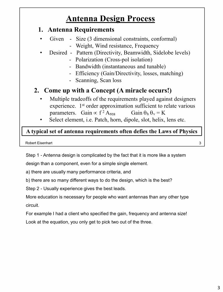
Antenna Design Process
A typical set of antenna requirements often defies the Laws of PhysicsA typical set of antenna requirements often defies the Laws of Physics
1. Antenna Requirements
• Given - Size (3 dimensional constraints, conformal)
- Weight, Wind resistance, Frequency
• Desired - Pattern (Directivity, Beamwidth, Sidelobe levels)
- Polarization (Cross-pol isolation)
- Bandwidth (instantaneous and tunable)
- Efficiency (Gain/Directivity, losses, matching)
- Scanning, Scan loss
• Multiple tradeoffs of the requirements played against designers
experience. 1st order approximation sufficient to relate various
parameters. Gain f 2 Area Gain h v = K
• Select element, i.e. Patch, horn, dipole, slot, helix, lens etc.
2. Come up with a Concept (A miracle occurs!)
3Robert Eisenhart
Step 1 - Antenna design is complicated by the fact that it is more like a system
design than a component, even for a simple single element.
a) there are usually many performance criteria, and
b) there are so many different ways to do the design, which is the best?
Step 2 - Usually experience gives the best leads.
More education is necessary for people who want antennas than any other type
circuit.
For example I had a client who specified the gain, frequency and antenna size!
Look at the equation, you only get to pick two out of the three.
3

Antenna Design Process (cont’d)
3. Break down concept into definable problem areas
and develop precise characterization for each.
• Single element performance (match, bandwidth, etc.)
• Mutual coupling effects in arrays
• Feed design
• Mechanical layout
4. Finalize Prototype design and Fabricate
5. Evaluate Prototype with chamber testing
6. Iterate design as needed
1. Closed form solutions rarely exist for real antennas
2. Arrays are needed to satisfy most antenna requirements
3. With radiation, physical influences on performance come
from well beyond the model
1. Closed form solutions rarely exist for real antennas
2. Arrays are needed to satisfy most antenna requirements
3. With radiation, physical influences on performance come
from well beyond the model
4Robert Eisenhart
Step 3 – Isolate various parts that can be dealt with independently.
Step 4 – Assemble design and build.
Step 5 - Test and evaluate (note: the “virtual lab” concept doesn’t work quite as
well with antennas, usually because the models are not as accurate/complete)
Step 6 – Decide when to stop, because
Modeling antennas is tougher than closed circuits
Consider an antenna as a circuit element.
4

An Antenna as a 2-port Circuit Component
Feed Port• Connects to a system with single mode
transmission line (coax, waveguide etc.)
• Primary issue – impedance match
• S-parameter characterization
Free Space Port• Deals with Energy distribution
• Radiation environment – terminated in
perfect match
• Electric field distribution is determined
on outer boundary
• Post processing interprets the boundary
field distribution as a new distribution
at R = (far field).
• This far field distribution2 is called the
antenna pattern
• Pattern characterized by # and direction
of beams, mainbeam gain*, beamwidth,
sidelobe levels & polarization.
• Pattern plotted vs. angular position on
spherical surface
* Antenna does not amplify:
Gain directive power
relative to isotropic power
Feed Port
R
Free-space port
as R
5Robert Eisenhart
Really just a two-port circuit, consider then the Feed Port
Transmission line choice is determined by impedance level, type of radiator, and
mechanical / configurational criteria. A great deal of “antenna” design is in the feed
components, particularly for arrays
Free space Port
Most of the design of antenna patterns is done mathematically through
determination of the excitation (mag & Phase) of multiple elements of an array.
These values are then part of the requirements for the Feed Port which sets these
excitation values for the elements.
So let’s look at some example designs.
5
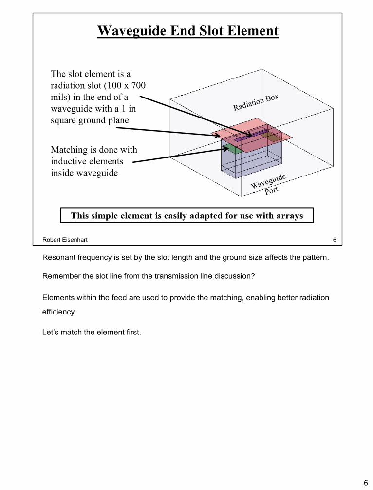
Waveguide End Slot Element
This simple element is easily adapted for use with arraysThis simple element is easily adapted for use with arrays
The slot element is a
radiation slot (100 x 700
mils) in the end of a
waveguide with a 1 in
square ground plane
Matching is done with
inductive elements
inside waveguide
6Robert Eisenhart
Resonant frequency is set by the slot length and the ground size affects the pattern.
Remember the slot line from the transmission line discussion?
Elements within the feed are used to provide the matching, enabling better radiation
efficiency.
Let’s match the element first.
6

Matching Process at 8.5 GHz
Add inductive irises to cancel susceptance in radiating slotAdd inductive irises to cancel susceptance in radiating slot
Determine
Impedance
= 0.284 -46
1
Determine
Position
= 0.284 -107
2
Determine
Dimensions
= 0.002 42
3
7Robert Eisenhart
Matching is a simple three step process for this element. First see what it is you
have to match on the Smith Chart Grid.
Shift reference plane to G = 1 curve on the Smith Chart.
Add symmetrical inductance elements. Resulting in excellent match
Let’s see the patterns
7

Single Slot E & H Plane Patterns
Radiation condition used on Radiation BoxRadiation condition used on Radiation Box
E-plane H-planeNormal to slot Aligned with slot
8Robert Eisenhart
A few comments on these pattern cuts. Pattern goes beyond 90 degrees because
of the limited size ground plane. E-plane has a broader pattern because the
element extent is smaller in that plane. Conversely, the larger the element, the
narrower the pattern.
So what if we used a larger or different ground plane?
8
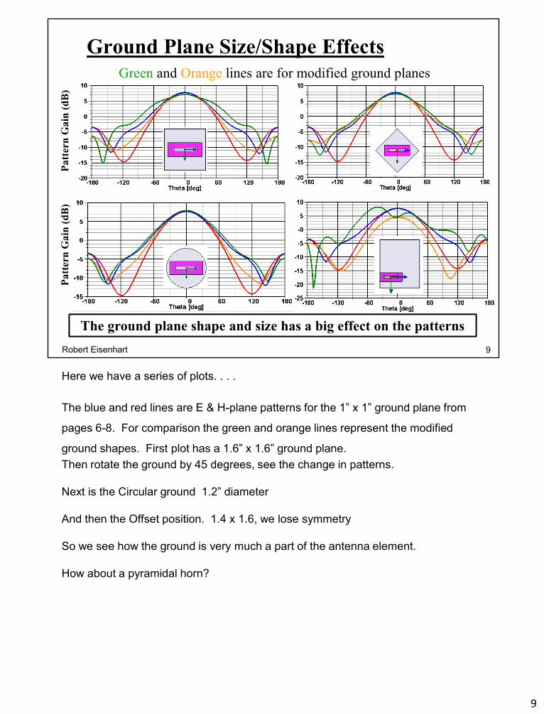
Ground Plane Size/Shape Effects
The ground plane shape and size has a big effect on the patternsThe ground plane shape and size has a big effect on the patterns
Pa
tter
n G
ain
(d
B)
Pa
tter
n G
ain
(d
B)
Green and Orange lines are for modified ground planes
9Robert Eisenhart
Here we have a series of plots. . . .
The blue and red lines are E & H-plane patterns for the 1” x 1” ground plane from
pages 6-8. For comparison the green and orange lines represent the modified
ground shapes. First plot has a 1.6” x 1.6” ground plane.
Then rotate the ground by 45 degrees, see the change in patterns.
Next is the Circular ground 1.2” diameter
And then the Offset position. 1.4 x 1.6, we lose symmetry
So we see how the ground is very much a part of the antenna element.
How about a pyramidal horn?
9
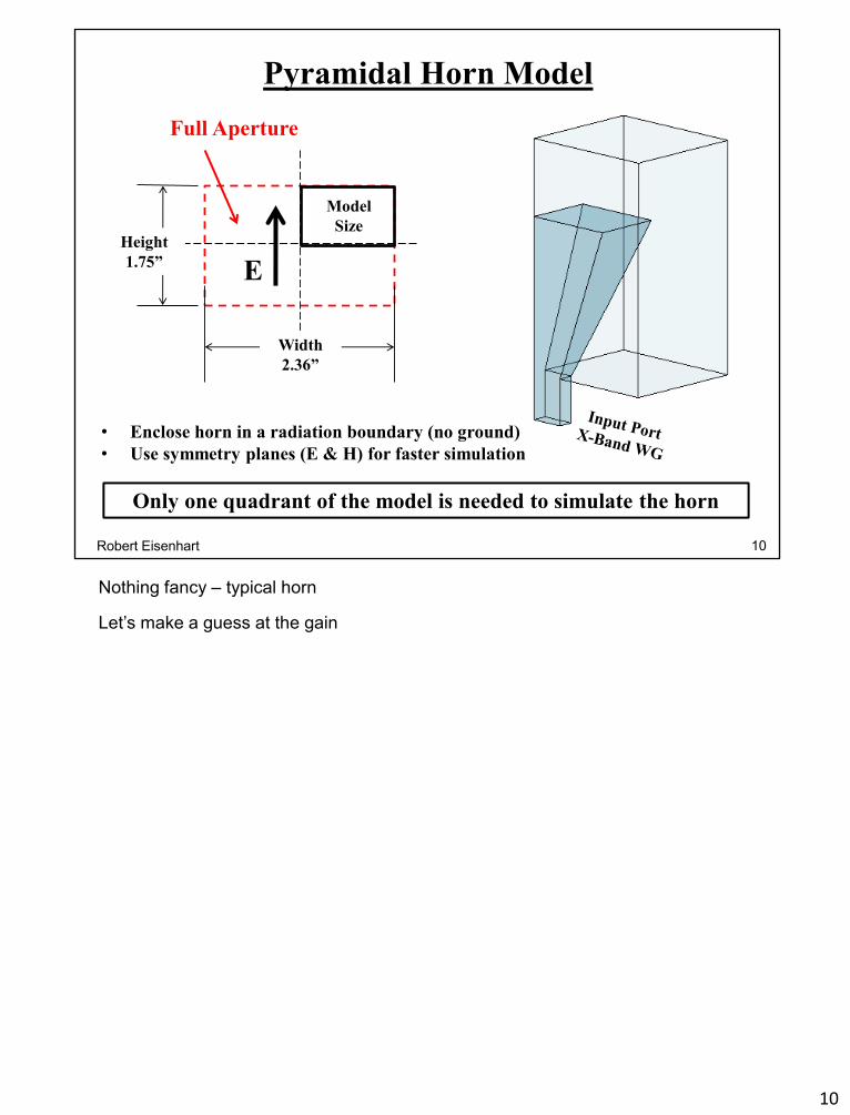
Pyramidal Horn Model
• Enclose horn in a radiation boundary (no ground)
• Use symmetry planes (E & H) for faster simulation
Only one quadrant of the model is needed to simulate the horn Only one quadrant of the model is needed to simulate the horn
Full Aperture
Model
SizeHeight
1.75”
Width
2.36”
E
10Robert Eisenhart
Nothing fancy – typical horn
Let’s make a guess at the gain
10

What is the Pyramidal Horn Gain?
It’s always smart to have a good idea of what to expect as the answerIt’s always smart to have a good idea of what to expect as the answer
And at 10 GHz., knowing :
Where Ae = Effective Area
0.85 Area,
And λ = 1.18”
Full Horn
ApertureHeight
1.75”
Width
2.36”
We have the size:
Then Gain = (4 0.85) (1.75) (2.36) / (1.18)2 → 32
or Gain = 15 dB
11Robert Eisenhart
Reciprocity is an important characteristic with antennas as well as circuits. This ties
back to the earlier page of considering an antenna as a 2-port. The effective S12 or
S21 is the same whether receiving or transmitting. So, as a receiving antenna,
think in the concept of Effective Area (Ae) of an antenna – the collection ability to
an incoming EM plane wave, like a funnel to rain. That is, how big does the
antenna look to the incoming wave?
The Gain is directly proportional to the Effective Area normalized to lambda squared
and related to the physical area.
So without running the simulation we expect Gain = 15 dB.
The point is . . . called a sanity check. If the simulation resulted in Gain as 10
or 20 dB I would suspect that something is wrong.
Back to the horn.
11
Horn E & H Plane Patterns
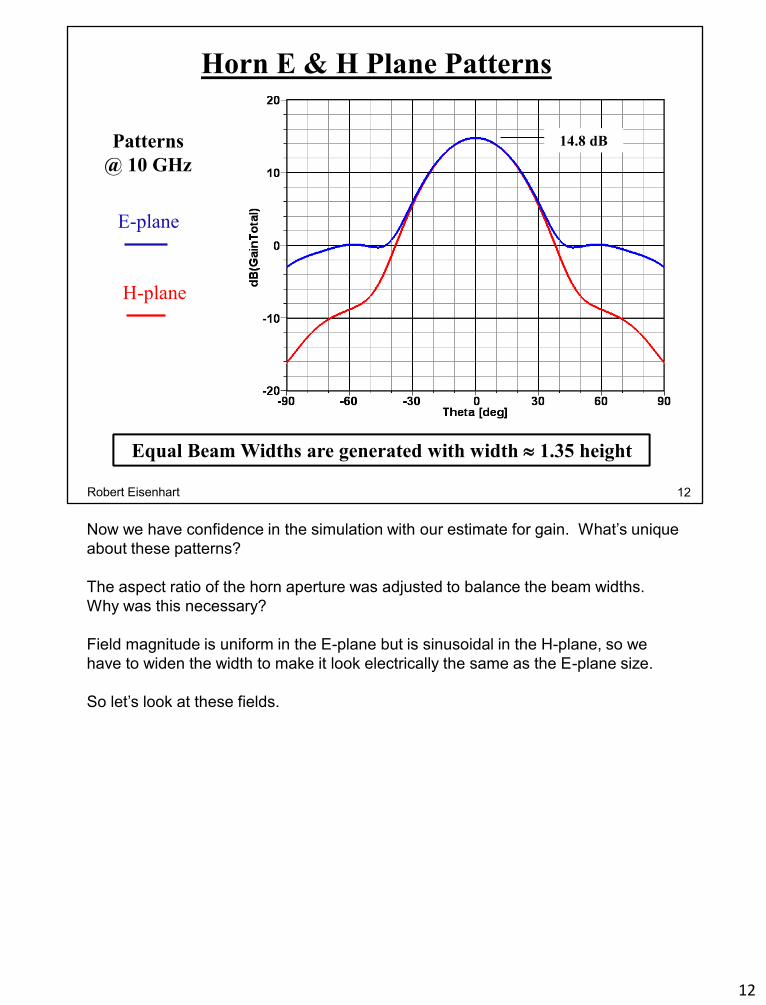
Equal Beam Widths are generated with width 1.35 heightEqual Beam Widths are generated with width 1.35 height
Patterns
@ 10 GHz
E-plane
H-plane
14.8 dB
12Robert Eisenhart
Now we have confidence in the simulation with our estimate for gain. What’s unique
about these patterns?
The aspect ratio of the horn aperture was adjusted to balance the beam widths.
Why was this necessary?
Field magnitude is uniform in the E-plane but is sinusoidal in the H-plane, so we
have to widen the width to make it look electrically the same as the E-plane size.
So let’s look at these fields.
12

Horn E & H-Plane Fields
Note the “spillover” in the E-planeNote the “spillover” in the E-plane
Changing
Scale
13Robert Eisenhart
What’s going on around the horn?
If we put an array of horn apertures in a ground plane there would be strong
coupling along the E-plane axes due to current aligned with the E-fields. This would
occur also for an open ended element WG array.
What if we put a ground at the base of the horn?
13
Horn E-Plane Patterns with Large Ground
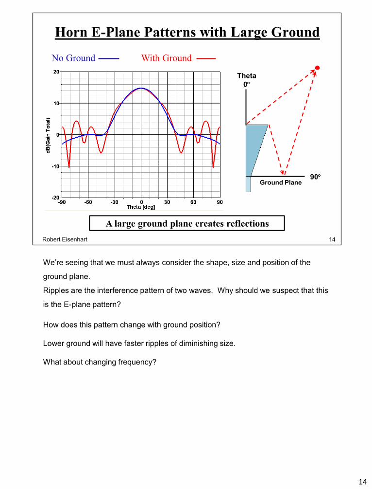
A large ground plane creates reflectionsA large ground plane creates reflections
No Ground With Ground
90
Theta
0
Ground Plane
14Robert Eisenhart
We’re seeing that we must always consider the shape, size and position of the
ground plane.
Ripples are the interference pattern of two waves. Why should we suspect that this
is the E-plane pattern?
How does this pattern change with ground position?
Lower ground will have faster ripples of diminishing size.
What about changing frequency?
14

Horn E-Plane Patterns vs. Frequency
Patterns for 8, 10 & 12 GHz
Important to understand the relationshipsImportant to understand the relationships
Where E H
are E & H plane
beamwidths
15Robert Eisenhart
Earlier we saw that gain is inversely proportional to lambda squared, so gain ~
freq2, so it “looks” bigger as the frequency increases.
Another useful “rule of thumb” is that the product of the two principal plane
beamwidths is inversely proportional to gain. i.e. higher gain – narrower beam.
Consider next a circular horn
15
Corrugated Horn & Radome Assembly
Assembly
Horn
Radome
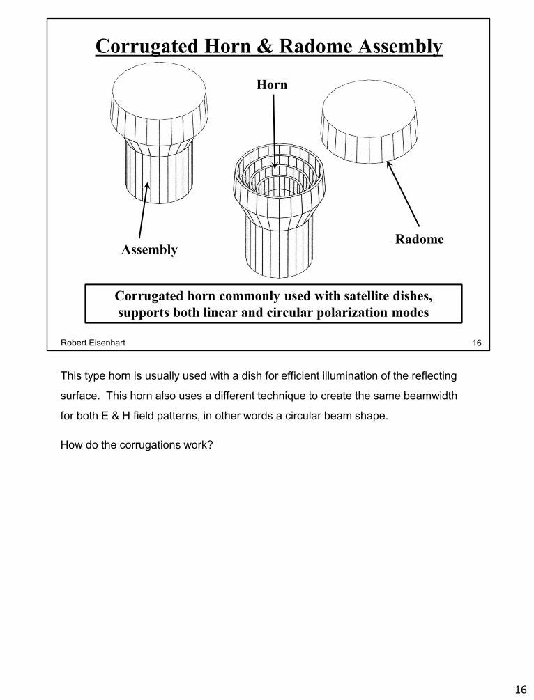
Corrugated horn commonly used with satellite dishes,
supports both linear and circular polarization modes
Corrugated horn commonly used with satellite dishes,
supports both linear and circular polarization modes
16Robert Eisenhart
This type horn is usually used with a dish for efficient illumination of the reflecting
surface. This horn also uses a different technique to create the same beamwidth
for both E & H field patterns, in other words a circular beam shape.
How do the corrugations work?
16

Corrugated Horn Cross-section
Corrugations suppress the E-plane edge currents to balance patternCorrugations suppress the E-plane edge currents to balance pattern
Radome
Circular
waveguide
throat
Complex shape required for casting – all axial surfaces are tapered at 1 deg.
Radome position tuned for best match – modeled with quadrant only
17Robert Eisenhart
Corrugations are ≈ λ/4 deep to appear as an open circuit at the opening to kill the
currents that flow in the E-plane, making the pattern circularly symmetric.
Corrugations have little effect on the H-plane.
This creates a low axial ratio for circularly polarized radiation along with a circular
pattern shape.
HFSS is ideal for designing because of the 1 deg taper, particularly in designing the
polarizer. This means that the cutoff frequency, lambda guide/gamma and guide
impedance are all a function of position along the guide!
A typical pattern set
17
Measured Corrugated Horn Patterns
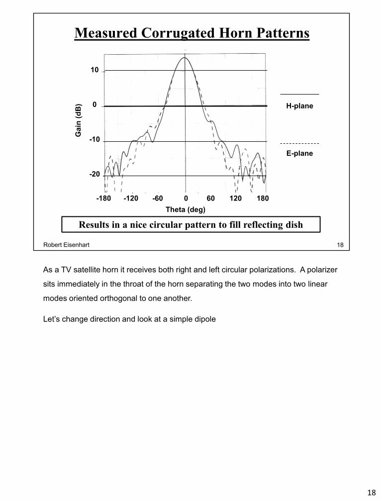
Results in a nice circular pattern to fill reflecting dishResults in a nice circular pattern to fill reflecting dish
-180 -120 -60 0 60 120 180
Theta (deg)
10
0
-10
-20
Ga
in (
dB
) H-plane
E-plane
18Robert Eisenhart
As a TV satellite horn it receives both right and left circular polarizations. A polarizer
sits immediately in the throat of the horn separating the two modes into two linear
modes oriented orthogonal to one another.
Let’s change direction and look at a simple dipole
18
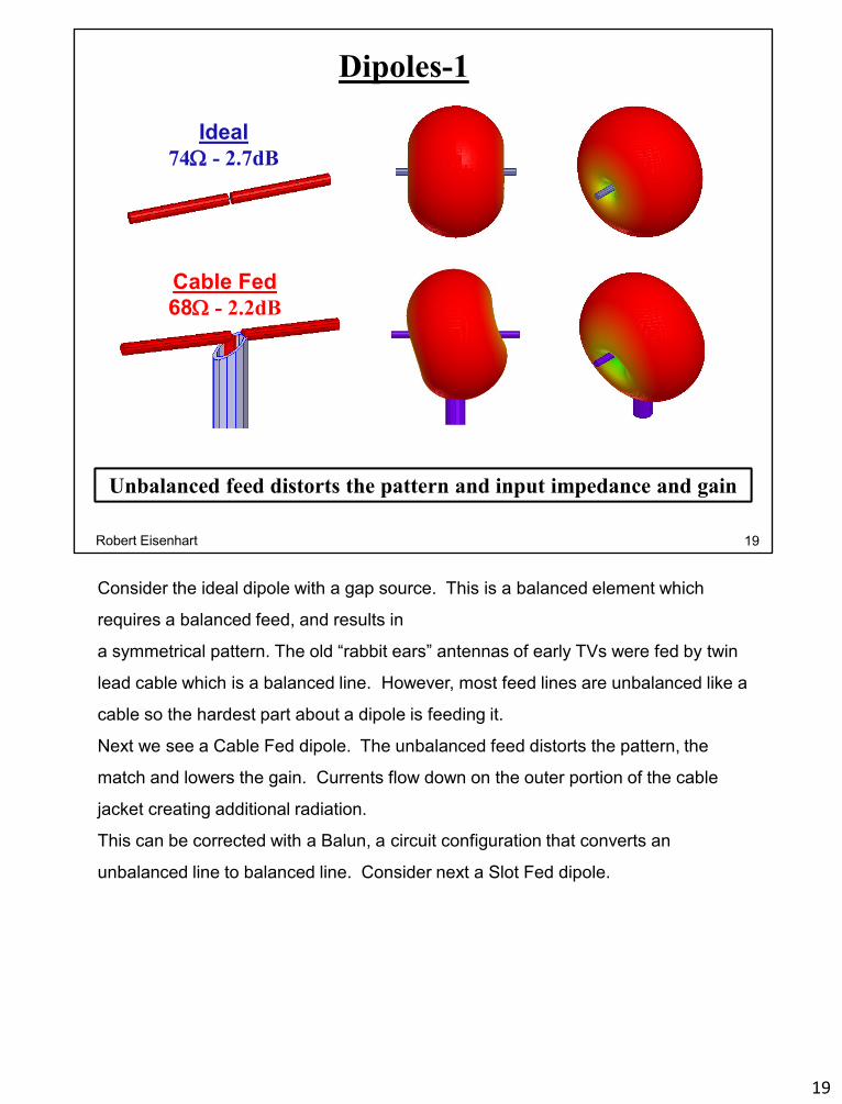
Dipoles-1
Ideal
74 - 2.7dB
Unbalanced feed distorts the pattern and input impedance and gainUnbalanced feed distorts the pattern and input impedance and gain
Cable Fed
68 - 2.2dB
19Robert Eisenhart
Consider the ideal dipole with a gap source. This is a balanced element which
requires a balanced feed, and results in
a symmetrical pattern. The old “rabbit ears” antennas of early TVs were fed by twin
lead cable which is a balanced line. However, most feed lines are unbalanced like a
cable so the hardest part about a dipole is feeding it.
Next we see a Cable Fed dipole. The unbalanced feed distorts the pattern, the
match and lowers the gain. Currents flow down on the outer portion of the cable
jacket creating additional radiation.
This can be corrected with a Balun, a circuit configuration that converts an
unbalanced line to balanced line. Consider next a Slot Fed dipole.
19
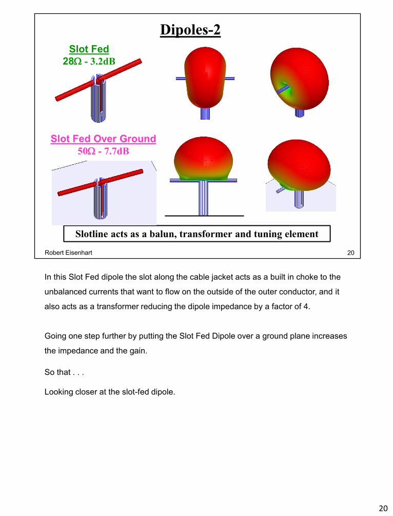
Dipoles-2
Slotline acts as a balun, transformer and tuning elementSlotline acts as a balun, transformer and tuning element
Slot Fed
28 - 3.2dB
Slot Fed Over Ground
50 - 7.7dB
20Robert Eisenhart
In this Slot Fed dipole the slot along the cable jacket acts as a built in choke to the
unbalanced currents that want to flow on the outside of the outer conductor, and it
also acts as a transformer reducing the dipole impedance by a factor of 4.
Going one step further by putting the Slot Fed Dipole over a ground plane increases
the impedance and the gain.
So that . . .
Looking closer at the slot-fed dipole.
20
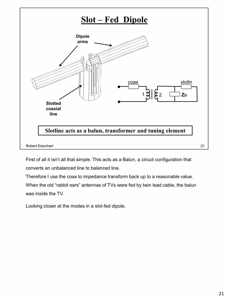
Slot – Fed Dipole
Dipole
arms
Slotted
coaxial
line
Slotline acts as a balun, transformer and tuning elementSlotline acts as a balun, transformer and tuning element
coax
1 2 ZD
slotln•
•
21Robert Eisenhart
First of all it isn’t all that simple. This acts as a Balun, a circuit configuration that
converts an unbalanced line to balanced line.
Therefore I use the coax to impedance transform back up to a reasonable value.
When the old “rabbit ears” antennas of TVs were fed by twin lead cable, the balun
was inside the TV.
Looking closer at the modes in a slot-fed dipole.
21

Coax
Center
Conductor
Bottom slot
Top Slot
Coax
Outer
Conductor
Dielectric
Sleeve
Slotted Coaxial Line
Slotline line has two independent TEM modesSlotline line has two independent TEM modes
File 5-Dipole
No Dielectric
in the slots
22Robert Eisenhart
Having three separate conductors will support 2 TEM modes. How do we
characterize these modes?
First we have the coax mode -
22

Slotted Coaxial Line Characterization
Coax Mode
Zc - 36.2
er - 3.17
No dielectric in the slot results in a lower effective er for that modeNo dielectric in the slot results in a lower effective er for that mode
Slot Mode
Zc - 51.7
er - 2.72
+
_
_
_
+
23Robert Eisenhart
The Coax mode ignores the slots, with the impedance set by the center diameter
and the internal dielectric.
Slot mode has the impedance set by the slot size and an effective dielectric, from
both the air in the slot and the dielectric around it.
Consider how you would determine the line characteristics for the Slot mode without
HFSS?
The dipole is still just a dipole, the trick here is driving it with unbalanced coax line,
often with some antennas, the balun is the hardest part to design.
Another interesting antenna element is the turnstile
23
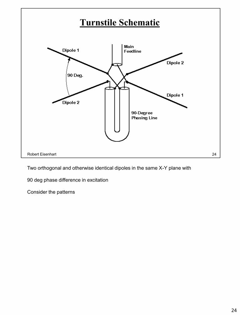
Turnstile Schematic
24Robert Eisenhart
Two orthogonal and otherwise identical dipoles in the same X-Y plane with
90 deg phase difference in excitation
Consider the patterns
24

Turnstile Antenna Dipoles
1 2
Dipole 2
Dipoles 1 & 2,
same phaseDipole 1
Dipoles 1 & 2,
90 deg phase
25Robert Eisenhart
This is really an array, but often considered as an antenna element. You can feed
the dipoles independently to get various patterns
Dipole one only
Dipole two only, or
Dipoles together, same phase, and
with the 90 deg difference
Resulting in a very nice circular pattern with horizontal polarization
25
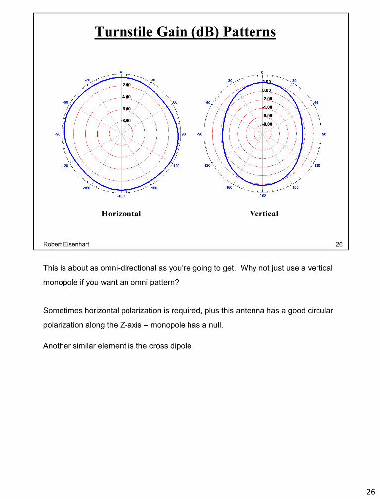
Turnstile Gain (dB) Patterns
Horizontal Vertical
26Robert Eisenhart
This is about as omni-directional as you’re going to get. Why not just use a vertical
monopole if you want an omni pattern?
Sometimes horizontal polarization is required, plus this antenna has a good circular
polarization along the Z-axis – monopole has a null.
Another similar element is the cross dipole
26

Cross Dipole Antenna
Match
.18 / -108 degHorizontal Vertical
27Robert Eisenhart
This only requires one feed, and the 90 deg delta phase shift is created by
shortening one dipole to make it capacitive and lengthening the other to be
inductive.
Very nice omni pattern,
and can be well matched
You have to have a single element before you can expand to arrays.
27

28Robert Eisenhart
Science aims to
understand the origins,
nature, and behavior of
the universe.
Engineering aims to use
that knowledge to enhance
our quality of life.
Clarifying the differences in the disciplines.
28