Embed Size (px)
Citation preview

190-00498-07 Rev. A Garmin G1000 Pilot’s Guide for Cessna Nav III 133
FLIGHT MANAGEMENT
SYSTEMO
VERVIEWFLIG
HTIN
STRUMEN
TSEIS
AUDIO
PANEL
& CN
SFLIG
HTM
ANAG
EMEN
THAZARD
AVOIDAN
CEAFCS
ADD
ITION
ALFEATURES
APPEND
ICESIN
DEX
SECTION 5 FLIGHT MANAGEMENT
5.1 INTRODUCTION
The G1000 is an integrated flight, engine, communication, navigation and surveillance system. This section of the Pilot’s Guide explains flight management using the G1000.
The most prominent part of the G1000 are the two full color displays: one Primary Flight Display (PFD) and one Multi Function Display (MFD). The information to successfully navigate the aircraft using the GPS sensors is displayed on the PFD and the MFD. See examples in the Figure 5-1 and Figure 5-2. Detailed descriptions of GPS navigation functions are discussed later in this section.
A brief description of the GPS navigation data on the PFD and MFD follows.
Navigation mode indicates which sensor is providing the course data (e.g., GPS, VOR) and the flight plan phase (e.g., Departure (DPRT), Terminal (TERM), Enroute (ENR), Oceanic (OCN), Approach (LNAV, LNAV+V, L/VNAV, or LPV), or Missed Approach (MAPR)). L/VNAV and LPV approaches are only available with SBAS.
The Inset Map is a small version of the MFD Navigation Map and can be displayed in the lower left corner of the PFD. When the system is in reversionary mode, the Inset Map is displayed in the lower right corner. The Inset Map is displayed by pressing the INSET Softkey. Pressing the INSET Softkey again, then pressing the OFF Softkey removes the Inset Map.
The Navigation Map displays aviation data (e.g., airports, VORs, airways, airspaces), geographic data (e.g., cities, lakes, highways, borders), topographic data (map shading indicating elevation), and hazard data (e.g., traffic, terrain, weather). The amount of displayed data can be reduced by pressing the DCLTR Softkey. The Navigation Map can be oriented four different ways: North Up (NORTH UP), Track Up (TRK UP), Desired Track Up (DTK UP), or Heading Up (HDG UP).
An aircraft icon is placed on the Navigation Map at the location corresponding to the calculated present position. The aircraft position and the flight plan legs are accurately based on GPS calculations. The basemap upon which these are placed are from a source with less resolution, therefore the relative position of the aircraft to map features is not exact. The leg of the active flight plan currently being flown is shown as a magenta line on the navigation map. The other legs are shown in white.
There are 28 different map ranges available, from 500 feet to 2000 nm. The current range is indicated in the lower right corner of the map and represents the top-to-bottom distance covered by the map. To change the map range on any map, turn the Joystick counter-clockwise to zoom in ( -, decreasing), or clockwise to zoom out (+, increasing).
The Direct-to Window, the Flight Plan Window, the Procedures Window, and the Nearest Airports Window can be displayed in the lower right corner of the PFD. Details of these windows are discussed in detail later in the section.

Garmin G1000 Pilot’s Guide for Cessna Nav III 190-00498-07 Rev. A134
FLIGHT MANAGEMENT
SYST
EMO
VERV
IEW
FLIG
HTIN
STRU
MEN
TSEI
SAU
DIO
PAN
EL&
CN
SFL
IGHT
MAN
AGEM
ENT
HAZA
RDAV
OID
ANCE
AFCS
ADD
ITIO
NAL
FEAT
URES
APPE
ND
ICES
IND
EX
Figure 5-1 GPS Navigation Information on the PFD
Location of:- Direct To Window- Flight Plan Window- Procedures Window- Nearest Airports Window
Inset Map
Navigation Status Box
Navigation Mode
Figure 5-2 GPS Navigation Information on the MFD Navigation Page
Active Flight Plan Leg
Navigation Map- Aviation Data
- Geographic Data- Topographic Data
- Hazard Data
Navigation Status Box
Aircraft Iconat Present Position
Navigation Page Title
Map Range
Map Orientation
Flight Plan Leg
NAVIGATION STATUS BOXThe Navigation Status Box located at the top of the PFD contains two fields displaying the following
information:
PFD Navigation Status Box
190-00498-07 Rev. A Garmin G1000 Pilot’s Guide for Cessna Nav III 135
FLIGHT MANAGEMENT
SYSTEMO
VERVIEWFLIG
HTIN
STRUMEN
TSEIS
AUDIO
PANEL
& CN
SFLIG
HTM
ANAG
EMEN
THAZARD
AVOIDAN
CEAFCS
ADD
ITION
ALFEATURES
APPEND
ICESIN
DEX
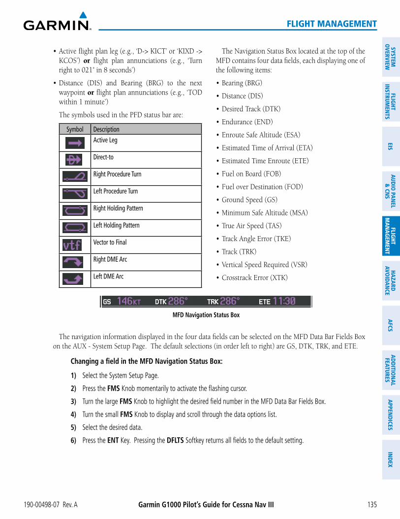
KCOS’) orright to 021˚ in 8 seconds’)
waypoint orwithin 1 minute’)
The symbols used in the PFD status bar are:
Symbol DescriptionActive Leg
Direct-to
Right Procedure Turn
Left Procedure Turn
Right Holding Pattern
Left Holding Pattern
Vector to Final
Right DME Arc
Left DME Arc
The Navigation Status Box located at the top of the MFD contains four data fields, each displaying one of the following items:
MFD Navigation Status Box
The navigation information displayed in the four data fields can be selected on the MFD Data Bar Fields Box
Changing a field in the MFD Navigation Status Box:
1) Select the System Setup Page.
2) Press the FMS Knob momentarily to activate the flashing cursor.
3) Turn the large FMS Knob to highlight the desired field number in the MFD Data Bar Fields Box.
4) Turn the small FMS Knob to display and scroll through the data options list.
5) Select the desired data.
6) Press the ENT Key. Pressing the DFLTS Softkey returns all fields to the default setting.

Garmin G1000 Pilot’s Guide for Cessna Nav III 190-00498-07 Rev. A136
FLIGHT MANAGEMENT
SYST
EMO
VERV
IEW
FLIG
HTIN
STRU
MEN
TSEI
SAU
DIO
PAN
EL&
CN
SFL
IGHT
MAN
AGEM
ENT
HAZA
RDAV
OID
ANCE
AFCS
ADD
ITIO
NAL
FEAT
URES
APPE
ND
ICES
IND
EX
5.2 USING MAP DISPLAYS
Map displays are used extensively in the G1000 to provide situational awareness in flight. Most G1000 maps can display the following information:
(highways, cities, lakes, rivers, borders, etc.) with names
to pointer, location of pointer, name, and other pertinent information)
Wind direction and speed
MAP ORIENTATIONMaps are shown in one of four different orientation options, allowing flexibility in determining aircraft
position relative to other items on the map (north up) or for determining where map items are relative to where the aircraft is going (track up, desired track up, or heading up). The map orientation is shown in the upper right corner of the map.
Figure 5-3 Map Orientation
The information in this section applies to the following maps unless otherwise noted:

190-00498-07 Rev. A Garmin G1000 Pilot’s Guide for Cessna Nav III 137
FLIGHT MANAGEMENT
SYSTEMO
VERVIEWFLIG
HTIN
STRUMEN
TSEIS
AUDIO
PANEL
& CN
SFLIG
HTM
ANAG
EMEN
THAZARD
AVOIDAN
CEAFCS
ADD
ITION
ALFEATURES
APPEND
ICESIN
DEX
NOTE: When panning or reviewing active flight plan legs in a non-North Up orientation, the map does not show the map orientation nor the wind direction and speed.
NOTE: Map orientation can only be changed on the Navigation Map Page. Any other displays that show navigation data reflect the orientation selected for the Navigation Map Page:
Changing the Navigation Map orientation:
1) With the Navigation Map Page displayed, press the MENU Key. The cursor flashes on the ‘Map Setup’ option.
Figure 5-4 Navigation Map Page Menu Window
Map Setup Selection
2) Press the ENT Key to display the Map Setup Window.
3) Turn the large FMS Knob, or press the ENT Key once, to select the ‘ORIENTATION’ field.
Figure 5-5 Map Setup Menu Window - Map Group
Orientation Field
Map Group Selection

Garmin G1000 Pilot’s Guide for Cessna Nav III 190-00498-07 Rev. A138
FLIGHT MANAGEMENT
SYST
EMO
VERV
IEW
FLIG
HTIN
STRU
MEN
TSEI
SAU
DIO
PAN
EL&
CN
SFL
IGHT
MAN
AGEM
ENT
HAZA
RDAV
OID
ANCE
AFCS
ADD
ITIO
NAL
FEAT
URES
APPE
ND
ICES
IND
EX
4) Turn the small FMS Knob to select the desired orientation.
5) Press the ENT Key to select the new orientation.
6) Press the FMS Knob to return to the base page.
MAP RANGEThere are 28 different map ranges available, from 500 feet to 2000 nm. The current range is indicated in
the lower right corner of the map and represents the top-to-bottom distance covered by the map. When the map range is decreased to a point that exceeds the capability of the G1000 to accurately represent the map, a magnifying glass icon is shown to the left of the map range. To change the map range turn the Joystick counter-clockwise to decrease the range, or clockwise to increase the range.
Figure 5-6 Map Range
Range Overzoom
AUTO ZOOMAuto zoom allows the G1000 to change the map display range to the smallest range clearly showing the
active waypoint. Auto zoom can be overridden by adjusting the range with the Joystick, and remains until the active waypoint changes, a terrain or traffic alert occurs, the aircraft takes off, or the manual override times out (timer set on Map Setup Window).
If a terrain caution or warning occurs, any map page displaying TAWS/TERRAIN data automatically adjusts to the smallest map range clearly showing the highest priority alert. If a new traffic advisory alert occurs, any map page capable of displaying traffic advisory alerts automatically adjusts to the smallest map range clearly showing the traffic advisory. When terrain or traffic alerts clear, the map returns to the previous auto zoom range based on the active waypoint.
The auto zoom function can be turned on or off independently for the PFD and MFD. Control of the ranges
the Map Setup Window for the Map Group). These settings determine the minimum and maximum distance to display based upon the aircraft’s ground speed.
the map are decluttered. If this is not acceptable, lower the maximum look ahead time to a value that limits the auto zoom to an acceptable range.
awareness may not be what is desired. Increase the minimum look ahead time to a value that limits the auto zoom to a minimum range that provides acceptable situational awareness.

190-00498-07 Rev. A Garmin G1000 Pilot’s Guide for Cessna Nav III 139
FLIGHT MANAGEMENT
SYSTEMO
VERVIEWFLIG
HTIN
STRUMEN
TSEIS
AUDIO
PANEL
& CN
SFLIG
HTM
ANAG
EMEN
THAZARD
AVOIDAN
CEAFCS
ADD
ITION
ALFEATURES
APPEND
ICESIN
DEX
adjusted.
zoom is overridden by a manual adjustment of the range knob. At the expiration of this time, the auto
(2000 nm).
Figure 5-7 Map Setup Menu Window - Map Group, Auto Zoom
Auto Zoom:Off, MFD Only, PFD Only, All On
Manual Range Override Expiration Time
Maximum Look Forward TimeMinimum Look Forward Time
Configuring automatic zoom:
1) Press the MENU Key with the Navigation Map Page displayed. The cursor flashes on the ‘Map Setup’ option.
2) Press the ENT Key. The Map Setup Menu is displayed.
3) Select the ‘Map’ group.
4) Press the ENT Key.
5) Highlight the ‘AUTO ZOOM’ field.
6) Select ‘Off’, ‘MFD Only’, ‘PFD Only’, or ‘ALL On’.
7) Press the ENT Key to accept the selected option. The flashing cursor highlights the ‘MAX LOOK FWD’ field. Times are from zero to 999 minutes.
8) Use the FMS Knobs to set the time. Press the ENT Key.
9) Repeat step 8 for ‘MIN LOOK FWD’ (zero to 99 minutes) and ‘TIME OUT’ (zero to 99 minutes).
10) Press the FMS Knob to return to the Navigation Map Page.

Garmin G1000 Pilot’s Guide for Cessna Nav III 190-00498-07 Rev. A140
FLIGHT MANAGEMENT
SYST
EMO
VERV
IEW
FLIG
HTIN
STRU
MEN
TSEI
SAU
DIO
PAN
EL&
CN
SFL
IGHT
MAN
AGEM
ENT
HAZA
RDAV
OID
ANCE
AFCS
ADD
ITIO
NAL
FEAT
URES
APPE
ND
ICES
IND
EX
MAP PANNINGMap panning allows the pilot to:
When the panning function is selected by pressing the Joystick, the Map Pointer flashes on the map display. A window also appears at the top of the map display showing the latitude/longitude position of the pointer, the bearing and distance to the pointer from the aircraft’s present position, and the elevation of the land at the position of the pointer.
Figure 5-8 Navigation Map - Map Pointer Activated
Map Pointer
Map Pointer Information
NOTE: The map is normally centered on the aircraft’s position. If the map has been panned and there has been no pointer movement for about 60 seconds, the map reverts back to centered on the aircraft position and the flashing pointer is removed.

190-00498-07 Rev. A Garmin G1000 Pilot’s Guide for Cessna Nav III 141
FLIGHT MANAGEMENT
SYSTEMO
VERVIEWFLIG
HTIN
STRUMEN
TSEIS
AUDIO
PANEL
& CN
SFLIG
HTM
ANAG
EMEN
THAZARD
AVOIDAN
CEAFCS
ADD
ITION
ALFEATURES
APPEND
ICESIN
DEX
When the Map Pointer is placed on an object, the name of the object is highlighted (even if the name was not originally displayed on the map). When any map feature or object is selected on the map display, pertinent information is displayed.
Figure 5-9 Navigation Map - Map Pointer on Point of Interest
Map Pointer on POI
Information about Point of Interest
When the Map Pointer crosses an airspace boundary, the boundary is highlighted and airspace information is shown at the top of the display. The information includes the name and class of airspace, the ceiling in feet above Mean Sea Level (MSL), and the floor in feet MSL.
Figure 5-10 Navigation Map - Map Pointer on Airspace
Map Pointer on Airspace
Informationabout Airspace

Garmin G1000 Pilot’s Guide for Cessna Nav III 190-00498-07 Rev. A142
FLIGHT MANAGEMENT
SYST
EMO
VERV
IEW
FLIG
HTIN
STRU
MEN
TSEI
SAU
DIO
PAN
EL&
CN
SFL
IGHT
MAN
AGEM
ENT
HAZA
RDAV
OID
ANCE
AFCS
ADD
ITIO
NAL
FEAT
URES
APPE
ND
ICES
IND
EX
Panning the map:
1) Press the Joystick to display the Map Pointer.
2) Move the Joystick to move the Map Pointer around the map.
3) Press the Joystick to remove the Map Pointer and recenter the map on the aircraft’s current position.
Reviewing information for an airport, NAVAID, or user waypoint:
1) Place the Map Pointer on a waypoint.
2) Press the ENT Key to display the Waypoint Information Page for the selected waypoint.
3) Press the GO BACK Softkey, the CLR Key, or the ENT Key to exit the Waypoint Information Page and return to the Navigation Map showing the selected waypoint.
Figure 5-11 Navigation Map - Information Window - NAVAID
NAVAID Information
GO BACK Softkey

190-00498-07 Rev. A Garmin G1000 Pilot’s Guide for Cessna Nav III 143
FLIGHT MANAGEMENT
SYSTEMO
VERVIEWFLIG
HTIN
STRUMEN
TSEIS
AUDIO
PANEL
& CN
SFLIG
HTM
ANAG
EMEN
THAZARD
AVOIDAN
CEAFCS
ADD
ITION
ALFEATURES
APPEND
ICESIN
DEX
Viewing airspace information for a special-use or controlled airspace:
1) Place the Map Pointer on an open area within the boundaries of an airspace.
2) Press the ENT Key to display an options menu.
3) ‘Review Airspaces’ should already be highlighted, if not select it. Press the ENT Key to display the Airspace Information Page for the selected airspace.
4) Press the CLR or ENT Key to exit the Airspace Information Page.
Figure 5-12 Navigation Map - Information Window - Airspace
Airspace Information

Garmin G1000 Pilot’s Guide for Cessna Nav III 190-00498-07 Rev. A144
FLIGHT MANAGEMENT
SYST
EMO
VERV
IEW
FLIG
HTIN
STRU
MEN
TSEI
SAU
DIO
PAN
EL&
CN
SFL
IGHT
MAN
AGEM
ENT
HAZA
RDAV
OID
ANCE
AFCS
ADD
ITIO
NAL
FEAT
URES
APPE
ND
ICES
IND
EX
MEASURING BEARING AND DISTANCEDistance and bearing from the aircraft’s present position to any point on the viewable navigation map may be
and distance tool displays a dashed Measurement Line and a Measure Pointer to aid in graphically identifying points with which to measure. Lat/Long, distance and elevation data for the Measure Pointer is provided in a window at the top of the navigation map.
Measuring bearing and distance between any two points:
1) Press the MENU Key (with the Navigation Map Page displayed).
2) Highlight the ‘Measure Bearing/Distance’ field.
3) Press the ENT Key. A Measure Pointer is displayed on the map at the aircraft’s present position.
4) Move the Joystick to place the reference pointer at the desired location. The bearing and distance are displayed at the top of the map. Elevation at the current pointer position is also displayed. Pressing the ENT Key changes the starting point for measuring.
5) To exit the Measure Bearing/Distance option, press the Joystick; or select ‘Stop Measuring’ from the Page Menu and press the ENT Key.
Figure 5-13 Navigation Map - Measuring Bearing and Distance
Pointer Lat/LongMeasurement Information
Measurement Line
190-00498-07 Rev. A Garmin G1000 Pilot’s Guide for Cessna Nav III 145
FLIGHT MANAGEMENT
SYSTEMO
VERVIEWFLIG
HTIN
STRUMEN
TSEIS
AUDIO
PANEL
& CN
SFLIG
HTM
ANAG
EMEN
THAZARD
AVOIDAN
CEAFCS
ADD
ITION
ALFEATURES
APPEND
ICESIN
DEX
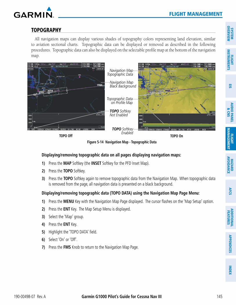
TOPOGRAPHYAll navigation maps can display various shades of topography colors representing land elevation, similar
to aviation sectional charts. Topographic data can be displayed or removed as described in the following procedures. Topographic data can also be displayed on the selectable profile map at the bottom of the navigation map.
Navigation Map Black Background
TOPO OffFigure 5-14 Navigation Map - Topographic Data
TOPO SoftkeyEnabled
Navigation Map Topographic Data
TOPO On
TOPO SoftkeyNot Enabled
Topographic Data on Profile Map
Displaying/removing topographic data on all pages displaying navigation maps:
1) Press the MAP Softkey (the INSET Softkey for the PFD Inset Map).
2) Press the TOPO Softkey.
3) Press the TOPO Softkey again to remove topographic data from the Navigation Map. When topographic data is removed from the page, all navigation data is presented on a black background.
Displaying/removing topographic data (TOPO DATA) using the Navigation Map Page Menu:
1) Press the MENU Key with the Navigation Map Page displayed. The cursor flashes on the ‘Map Setup’ option.
2) Press the ENT Key. The Map Setup Menu is displayed.
3) Select the ‘Map’ group.
4) Press the ENT Key.
5) Highlight the ‘TOPO DATA’ field.
6) Select ‘On’ or ‘Off’.
7) Press the FMS Knob to return to the Navigation Map Page.

Garmin G1000 Pilot’s Guide for Cessna Nav III 190-00498-07 Rev. A146
FLIGHT MANAGEMENT
SYST
EMO
VERV
IEW
FLIG
HTIN
STRU
MEN
TSEI
SAU
DIO
PAN
EL&
CN
SFL
IGHT
MAN
AGEM
ENT
HAZA
RDAV
OID
ANCE
AFCS
ADD
ITIO
NAL
FEAT
URES
APPE
ND
ICES
IND
EX
Figure 5-15 Navigation Map Setup Menu - TOPO DATA Setup
TOPO DATA On/Off
TOPO DATA Range
The topographic data range is the maximum map range on which topographic data is displayed.
NOTE: Since the PFD Inset Map is much smaller than the MFD navigation maps, items are removed on the PFD Inset Map two range levels smaller than the range selected in the Map Setup pages (e.g., a setting of 100 nm removes the item at ranges above 100 nm on MFD navigation maps, while the PFD Inset Map removes the same item at 50 nm).
Selecting a topographical data range (TOPO DATA):
1) Press the MENU Key with the Navigation Map Page displayed. The cursor flashes on the ‘Map Setup’ option.
2) Press the ENT Key. The Map Setup Menu is displayed.
3) Select the ‘Map’ group.
4) Press the ENT Key.
5) Highlight the ‘TOPO DATA’ range field. TOPO ranges are from 500 ft to 2000 nm.
6) To change the TOPO range setting, turn the small FMS Knob to display the range list.
7) Select the desired range using the small FMS Knob.
8) Press the ENT Key.
9) Press the FMS Knob to return to the Navigation Map Page.
In addition, the Navigation Map can display a topographic scale (located in the lower right hand side of the map) showing a scale of the terrain elevation and current elevation values.

190-00498-07 Rev. A Garmin G1000 Pilot’s Guide for Cessna Nav III 147
FLIGHT MANAGEMENT
SYSTEMO
VERVIEWFLIG
HTIN
STRUMEN
TSEIS
AUDIO
PANEL
& CN
SFLIG
HTM
ANAG
EMEN
THAZARD
AVOIDAN
CEAFCS
ADD
ITION
ALFEATURES
APPEND
ICESIN
DEX
Figure 5-16 Navigation Map - TOPO SCALE
Maximum Displayed Elevation
Minimum Displayed Elevation
Aircraft Altitude (MSL)
Ground Elevation at Map Pointer Location (only visible when Map Pointer is displayed)
Range of Displayed Elevations
Displaying/removing the topographic scale (TOPO SCALE):
1) Press the MENU Key with the Navigation Map Page displayed. The cursor flashes on the ‘Map Setup’ option.
2) Press the ENT Key. The Map Setup Menu is displayed.
3) Select the ‘Map’ group and press the ENT Key.
4) Highlight the ‘TOPO SCALE’ field.
5) Select ‘On’ or ‘Off’.
6) Press the FMS Knob to return to the Navigation Map Page.
Figure 5-17 Navigation Map Setup Menu - TOPO SCALE Setup
TOPO SCALE On/Off
Garmin G1000 Pilot’s Guide for Cessna Nav III 190-00498-07 Rev. A148
FLIGHT MANAGEMENT
SYST
EMO
VERV
IEW
FLIG
HTIN
STRU
MEN
TSEI
SAU
DIO
PAN
EL&
CN
SFL
IGHT
MAN
AGEM
ENT
HAZA
RDAV
OID
ANCE
AFCS
ADD
ITIO
NAL
FEAT
URES
APPE
ND
ICES
IND
EX
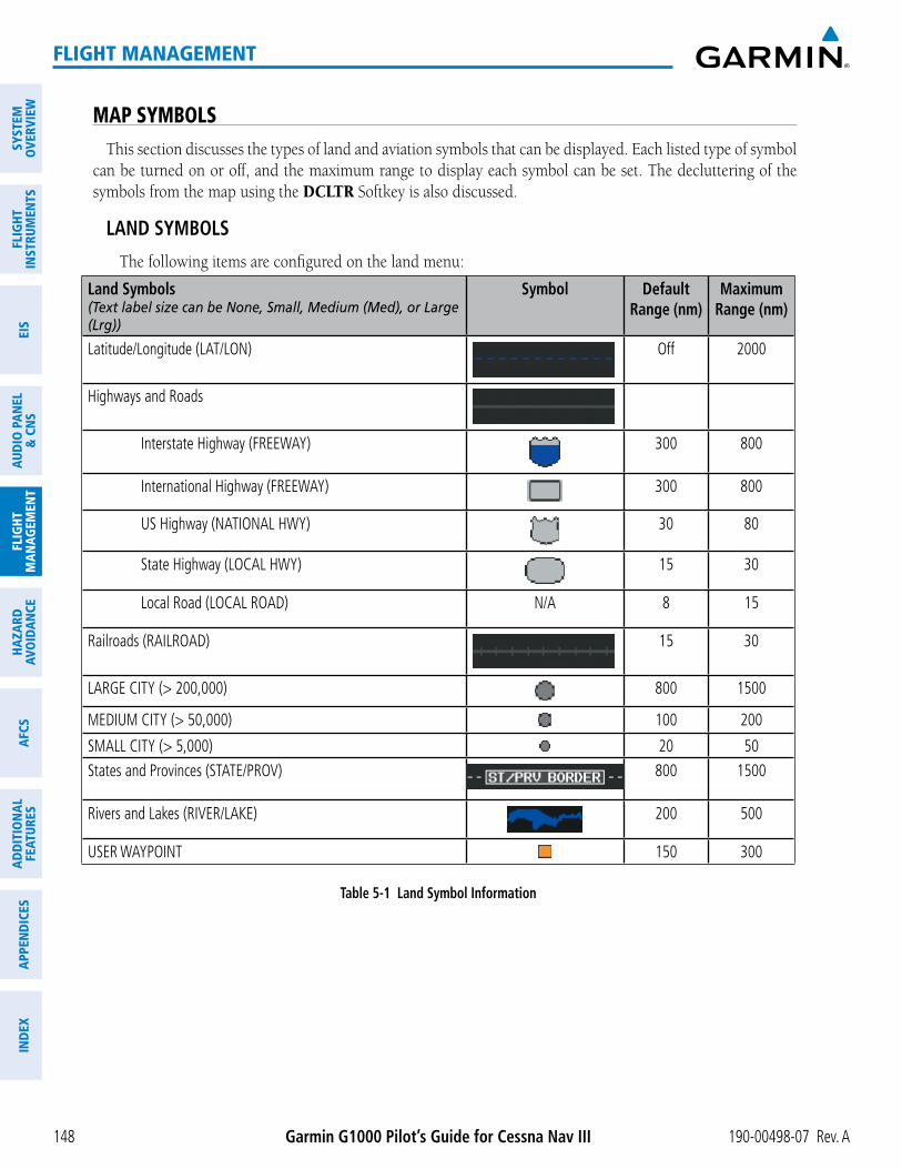
MAP SYMBOLSThis section discusses the types of land and aviation symbols that can be displayed. Each listed type of symbol
can be turned on or off, and the maximum range to display each symbol can be set. The decluttering of the symbols from the map using the DCLTR Softkey is also discussed.
LAND SYMBOLS The following items are configured on the land menu:
Land Symbols(Text label size can be None, Small, Medium (Med), or Large (Lrg))
Symbol Default Range (nm)
Maximum Range (nm)
Latitude/Longitude (LAT/LON) Off 2000
Highways and Roads
Interstate Highway (FREEWAY) 300 800
International Highway (FREEWAY) 300 800
US Highway (NATIONAL HWY) 30 80
State Highway (LOCAL HWY) 15 30
Local Road (LOCAL ROAD) N/A 8 15
Railroads (RAILROAD) 15 30
LARGE CITY (> 200,000) 800 1500
MEDIUM CITY (> 50,000) 100 200
SMALL CITY (> 5,000) 20 50States and Provinces (STATE/PROV) 800 1500
Rivers and Lakes (RIVER/LAKE) 200 500
USER WAYPOINT 150 300
Table 5-1 Land Symbol Information

190-00498-07 Rev. A Garmin G1000 Pilot’s Guide for Cessna Nav III 149
FLIGHT MANAGEMENT
SYSTEMO
VERVIEWFLIG
HTIN
STRUMEN
TSEIS
AUDIO
PANEL
& CN
SFLIG
HTM
ANAG
EMEN
THAZARD
AVOIDAN
CEAFCS
ADD
ITION
ALFEATURES
APPEND
ICESIN
DEX
AVIATION SYMBOLS The following items are configured on the aviation menu:
Aviation Symbols(Text label size can be None, Small, Medium (Med), or Large (Lrg))
Symbol Default Range (nm)
Maximum Range (nm)
Active Flight Plan Leg (ACTIVE FPL) 2000 2000
Non-active Flight Plan Leg (ACTIVE FPL) 2000 2000
Active Flight Plan Waypoint (ACTIVE FPL WPT) See Airports, NAVAIDs 2000 2000Large Airports (LARGE APT)
250 500Medium Airports (MEDIUM APT) 150 300Small Airports (SMALL APT) 50 100Taxiways (SAFETAXI) See Additional Features 3 20Runway Extension (RWY EXTENSION) N/A Off 100Intersection (INT WAYPOINT) 15 30
Non-directional Beacon (NDB WAYPOINT) 15 30
VOR (VOR WAYPOINT)
150 300
Class B Airspace/TMA (CLASS B/TMA) 200 500
Class C Airspace/TCA (CLASS C/TCA) 200 500
Class D Airspace (CLASS D) 150 300
Restricted Area (RESTRICTED) 200 500
Military Operations Area [MOA(MILITARY)] 200 500
Other/Air Defense Interdiction Zone (OTHER/ADIZ) 200 500
Temporary Flight Restriction (TFR) 500 2000
Table 5-2 Aviation Symbol Information

Garmin G1000 Pilot’s Guide for Cessna Nav III 190-00498-07 Rev. A150
FLIGHT MANAGEMENT
SYST
EMO
VERV
IEW
FLIG
HTIN
STRU
MEN
TSEI
SAU
DIO
PAN
EL&
CN
SFL
IGHT
MAN
AGEM
ENT
HAZA
RDAV
OID
ANCE
AFCS
ADD
ITIO
NAL
FEAT
URES
APPE
ND
ICES
IND
EX
SYMBOL SETUPAll pages with maps can display land symbols (roads, lakes, borders, etc). Land symbols can be removed
totally (turned off).
Displaying/removing all land symbols:
1) Press the MENU Key with the Navigation Map Page displayed. The Page Menu is displayed and the cursor flashes on the ‘Map Setup’ option.
2) Press the ENT Key. The Map Setup Group Menu is displayed and the cursor flashes on the ‘Map’ option.
3) Highlight the ‘LAND DATA’ field.
4) Select ‘On’ or ‘Off’.
5) Press the FMS Knob to return to the Navigation Map Page.
Figure 5-18 Navigation Map Setup Menu - LAND DATA Setup
LAND DATA On/Off
The range (RNG) sets the maximum range at which items appear on the display.
Selecting a ‘Land’ or ‘Aviation’ group item text size and range:
1) Press the MENU Key with the Navigation Map Page displayed. The cursor flashes on the ‘Map Setup’ option.
2) Press the ENT Key. The Map Setup Menu is displayed.
3) Select the ‘Land’ or ‘Aviation’ group.
4) Press the ENT Key. The cursor flashes on the first field.
5) Select the desired land option.
6) Select the desired text size.

190-00498-07 Rev. A Garmin G1000 Pilot’s Guide for Cessna Nav III 151
FLIGHT MANAGEMENT
SYSTEMO
VERVIEWFLIG
HTIN
STRUMEN
TSEIS
AUDIO
PANEL
& CN
SFLIG
HTM
ANAG
EMEN
THAZARD
AVOIDAN
CEAFCS
ADD
ITION
ALFEATURES
APPEND
ICESIN
DEX
7) Press the ENT Key to accept the selected size.
8) Select the desired range.
9) Press the ENT Key to accept the selected range.
10) Press the FMS Knob to return to the Navigation Map Page.
Figure 5-19 Navigation Map Setup Menu - LAND GROUP Setup
Maximum Display Range Text Label Size(None, Small, Med, or Lrg)
Figure 5-20 Navigation Map Setup Menu - AVIATION GROUP Setup
Maximum Display Range Text Label Size
(None, Small, Med, or Lrg)
NOTE: Since the PFD Inset Map is much smaller than the MFD navigation maps, items are removed on the PFD Inset Map two range levels smaller than the range selected in the Map Setup pages (e.g., a setting of 100 nm removes the item at ranges above 100 nm on MFD navigation maps, while the PFD Inset Map removes the same item at 50 nm).

Garmin G1000 Pilot’s Guide for Cessna Nav III 190-00498-07 Rev. A152
FLIGHT MANAGEMENT
SYST
EMO
VERV
IEW
FLIG
HTIN
STRU
MEN
TSEI
SAU
DIO
PAN
EL&
CN
SFL
IGHT
MAN
AGEM
ENT
HAZA
RDAV
OID
ANCE
AFCS
ADD
ITIO
NAL
FEAT
URES
APPE
ND
ICES
IND
EX
MAP DECLUTTERThe declutter feature allows the pilot to progressively step through four levels of removing map information.
The declutter level is displayed in the DCLTR Softkey and next to the Declutter Menu Option.
Figure 5-21 Navigation Map - Declutter Level Indications
Declutter Level
Navigation Map Page Menu
DCLTR Softkey
Decluttering the map:
Press the DCLTR Softkey with the Navigation Map Page displayed. The current declutter level is shown. With each softkey selection, another level of map information is removed.
Or:
1) Press the MENU Key with the Navigation Map Page displayed.
2) Select ‘Declutter’. The current declutter level is shown.
3) Press the ENT Key.
Decluttering the PFD Inset Map:
1) Press the INSET Softkey.
2) Press the DCLTR Softkey. The current declutter level is shown. With each selection, another level of map information is removed.

190-00498-07 Rev. A Garmin G1000 Pilot’s Guide for Cessna Nav III 153
FLIGHT MANAGEMENT
SYSTEMO
VERVIEWFLIG
HTIN
STRUMEN
TSEIS
AUDIO
PANEL
& CN
SFLIG
HTM
ANAG
EMEN
THAZARD
AVOIDAN
CEAFCS
ADD
ITION
ALFEATURES
APPEND
ICESIN
DEX
various levels of declutter.
Item No Declutter Declutter-1 Declutter-2 Declutter-3Flight Plan Route Lines X X X XFlight Plan Route Waypoints X X X XRivers/Lakes X X X XTopography Data X X X XInternational Borders X X X XTrack Vector X X X XNavigation Range Ring X X X XFuel Range Ring X X X XTerrain Data X X X XTraffic X X X XAirways X X X XNEXRAD X X XXM Lightning Data X X XAirports X X XRunway Labels X X XRestricted X X XMOA (Military) X X XUser Waypoints X XLatitude/Longitude Grid X XNAVAIDs X XClass B Airspaces/TMA X XClass C Airspaces/TCA X XClass D Airspaces X XOther Airspaces/ADIZ X XTFRs X XObstacles X XLand/Country Text XCities XRoads XRailroads XState/Province Boundaries XRiver/Lake Names X
Table 5-3 Navigation Map Items Displayed by Declutter Level

Garmin G1000 Pilot’s Guide for Cessna Nav III 190-00498-07 Rev. A154
FLIGHT MANAGEMENT
SYST
EMO
VERV
IEW
FLIG
HTIN
STRU
MEN
TSEI
SAU
DIO
PAN
EL&
CN
SFL
IGHT
MAN
AGEM
ENT
HAZA
RDAV
OID
ANCE
AFCS
ADD
ITIO
NAL
FEAT
URES
APPE
ND
ICES
IND
EX
AIRWAYSThis airways discussion is based upon the North American airway structure. The airway structure in places
other than North America vary by location, etc. and are not discussed in this book. Low Altitude Airways (or Victor Airways) primarily serve smaller piston-engine, propeller-driven airplanes on shorter routes and at lower altitudes. Airways are eight nautical miles wide and start 1,200 feet above ground level (AGL) and extend up to 18,000 feet mean sea level (MSL). Low Altitude Airways are designated with a “V” before the airway number (hence the name “Victor Airways”) since they run primarily between VORs.
High Altitude Airways (or Jet Routes) primarily serve airliners, jets, turboprops, and turbocharged piston aircraft operating above 18,000 feet MSL. Jet Routes start at 18,000 feet MSL and extend upward to 45,000 feet MSL (altitudes above 18,000 feet are called “flight levels” and are described as FL450 for 45,000 feet MSL). Jet Routes are designated with a “J” before the route number.
Low Altitude Airways are drawn in gray (the same shade used for roads). High Altitude Airways are drawn in green. When both types of airways are displayed, High Altitude Airways are drawn on top of Low Altitude Airways.
When airways are selected for display on the map, the airway waypoints (VORs, NDBs and Intersections) are also displayed.
Figure 5-22 Airways on MFD Navigation Page
Low Altitude Airway
(Victor Airway)
High Altitude Airway(Jet Route)

190-00498-07 Rev. A Garmin G1000 Pilot’s Guide for Cessna Nav III 155
FLIGHT MANAGEMENT
SYSTEMO
VERVIEWFLIG
HTIN
STRUMEN
TSEIS
AUDIO
PANEL
& CN
SFLIG
HTM
ANAG
EMEN
THAZARD
AVOIDAN
CEAFCS
ADD
ITION
ALFEATURES
APPEND
ICESIN
DEX
Airways may be displayed on the map at the pilot’s discretion using either a combination of AIRWAYS Softkey presses, or menu selections using the MENU Key from the Navigation Map Page. The Airway range can also be programmed to only display Airways on the MFD when the map range is at or below a specific number.
Displaying/removing airways:
1) Press the MAP Softkey.
2) Press the AIRWAYS Softkey. Both High and Low Altitude Airways are displayed (AIRWY ON).
3) Press the softkey again to display Low Altitude Airways only (AIRWY LO).
4) Press the softkey again to display High Altitude Airways only (AIRWY HI).
5) Press the softkey again to remove High Altitude Airways. No airways are displayed (AIRWAYS).
Or:
1) Press the MENU Key with the Navigation Map Page displayed. The cursor flashes on the ‘Map Setup’ option.
2) Press the ENT Key. The Map Setup Menu is displayed.
3) Turn the small FMS Knob to select the ‘Airways’ group, and press the ENT Key.
4) Turn the large FMS Knob to highlight the ‘AIRWAYS’ field.
5) Turn the FMS Knob to select ‘Off’, ‘All’, ‘LO Only’, or ‘HI Only’, and press the ENT Key.
6) Press the FMS Knob to return to the Navigation Map Page.
Figure 5-23 Navigation Map Setup Menu - AIRWAYS Setup
Low Altitude Airway Range
High Altitude Airway Range
Airway Display SelectionOff, All, LO Only, HI Only
The airway range is the maximum map range on which airways are displayed.
Selecting an airway range (LOW ALT AIRWAY or HI ALT AIRWAY):
1) Press the MENU Key with the Navigation Map Page displayed. The cursor flashes on the ‘Map Setup’ option.
2) Press the ENT Key. The Map Setup Menu is displayed.
3) Turn the small FMS Knob to select the ‘Airway’ group, and press the ENT Key.
4) Highlight the ‘LOW ALT AIRWAY’ or ‘HI ALT AIRWAY’ range field.
5) To change the range setting, turn the small FMS Knob to display the range list.
6) Select the desired range using the small FMS Knob.
7) Press the ENT Key.
8) Press the FMS Knob to return to the Navigation Map Page.

Garmin G1000 Pilot’s Guide for Cessna Nav III 190-00498-07 Rev. A156
FLIGHT MANAGEMENT
SYST
EMO
VERV
IEW
FLIG
HTIN
STRU
MEN
TSEI
SAU
DIO
PAN
EL&
CN
SFL
IGHT
MAN
AGEM
ENT
HAZA
RDAV
OID
ANCE
AFCS
ADD
ITIO
NAL
FEAT
URES
APPE
ND
ICES
IND
EX
The following range items are configurable on the airways menu:
Airway Type Symbol Default Range (nm)
Maximum Range (nm)
Low Altitude Airway (LOW ALT AIRWAY) 200 500
High Altitude Airway (HI ALT AIRWAY) 300 500
Table 5-4 Airway Range Information
TRACK VECTORThe Navigation Map can display a track vector that is useful in minimizing track angle error. The track vector
is a solid light blue line segment extended to a predicted location. The track vector look-ahead time is selectable (30 sec, 60 sec (default), 2 min, 5 min, 10 min, 20 min) and determines the length of the track vector. The track vector shows up to 90 degrees of a turn for the 30 and 60 second time settings.
Figure 5-24 Navigation Map -Track Vector
Track Vector
Displaying/removing the track vector:
1) Press the MENU Key with the Navigation Map Page displayed. The cursor flashes on the ‘Map Setup’ option.
2) Press the ENT Key. The Map Setup Menu is displayed.
3) Select the ‘Map’ group.
4) Press the ENT Key.
5) Highlight the ‘TRACK VECTOR’ field.
6) Select ‘On’ or ‘Off’. Press the ENT Key to accept the selected option. The flashing cursor highlights the look ahead time field. Use the FMS Knob to select the desired time. Press the ENT Key.
7) Press the FMS Knob to return to the Navigation Map Page.

190-00498-07 Rev. A Garmin G1000 Pilot’s Guide for Cessna Nav III 157
FLIGHT MANAGEMENT
SYSTEMO
VERVIEWFLIG
HTIN
STRUMEN
TSEIS
AUDIO
PANEL
& CN
SFLIG
HTM
ANAG
EMEN
THAZARD
AVOIDAN
CEAFCS
ADD
ITION
ALFEATURES
APPEND
ICESIN
DEX
Figure 5-25 Navigation Map Setup Menu -TRACK VECTOR, WIND VECTOR, NAV RANGE RING, FUEL RANGE RING Setup
Track Vector - On/Off - Look Ahead Time
Fuel Range - On/Off - Fuel Reserve Time
Wind Vector On/Off
Nav Range Ring On/Off
WIND VECTORThe map displays a wind vector arrow in the upper right-hand portion of the screen. Wind vector information
is displayed as a white arrow pointing in the direction in which the wind is moving for wind speeds greater than
Figure 5-26 Navigation Map - Wind Vector
Wind Direction Wind Speed
NOTE: The wind vector is not displayed until the aircraft is moving. It is not displayed on the Waypoint Information pages.
Displaying/removing the wind vector:
1) Press the MENU Key with the Navigation Map Page displayed. The cursor flashes on the ‘Map Setup’ option.
2) Press the ENT Key. The Map Setup Menu is displayed.
3) Select the ‘Map’ group.
4) Press the ENT Key.
5) Highlight the ‘WIND VECTOR’ field.
6) Select ‘On’ or ‘Off’.
7) Press the FMS Knob to return to the Navigation Map Page.

Garmin G1000 Pilot’s Guide for Cessna Nav III 190-00498-07 Rev. A158
FLIGHT MANAGEMENT
SYST
EMO
VERV
IEW
FLIG
HTIN
STRU
MEN
TSEI
SAU
DIO
PAN
EL&
CN
SFL
IGHT
MAN
AGEM
ENT
HAZA
RDAV
OID
ANCE
AFCS
ADD
ITIO
NAL
FEAT
URES
APPE
ND
ICES
IND
EX
NAV RANGE RINGThe Nav Range Ring shows the direction of travel (ground track) on a rotating compass card. The range is
determined by the map range. The range is 1/4 of the map range (e.g., 37.5 nm on a 150 nm map).
Figure 5-27 Navigation Map - Nav Range Ring
Nav Range Ring
Range (radius)
NOTE: The Nav Range Ring is not displayed on the Waypoint Information pages, Nearest pages, or Direct-to Window map.
Displaying/removing the Nav Range Ring:
1) Press the MENU Key with the Navigation Map Page displayed. The cursor flashes on the ‘Map Setup’ option.
2) Press the ENT Key. The Map Setup Menu is displayed.
3) Select the ‘Map’ group.
4) Press the ENT Key.
5) Highlight the ‘NAV RANGE RING’ field.
6) Select ‘On’ or ‘Off’.
7) Press the FMS Knob to return to the Navigation Map Page.
NOTE: The Nav Range Ring is referenced to either magnetic or true north, based on the selection on the AUX - System Setup Page.

190-00498-07 Rev. A Garmin G1000 Pilot’s Guide for Cessna Nav III 159
FLIGHT MANAGEMENT
SYSTEMO
VERVIEWFLIG
HTIN
STRUMEN
TSEIS
AUDIO
PANEL
& CN
SFLIG
HTM
ANAG
EMEN
THAZARD
AVOIDAN
CEAFCS
ADD
ITION
ALFEATURES
APPEND
ICESIN
DEX
FUEL RANGE RINGThe map can display a fuel range ring which shows the remaining flight distance. A dashed green circle
indicates the selected range to reserve fuel. A solid green circle indicates the total endurance range. If only reserve fuel remains, the range is indicated by a solid yellow circle.
Figure 5-28 Navigation Map - Fuel Range Ring
Range to Reserve Fuel
Total Endurance RangeTime to Reserve Fuel
Displaying/removing the fuel range ring and selecting a fuel range time:
1) Press the MENU Key with the Navigation Map Page displayed. The cursor flashes on the ‘Map Setup’ option.
2) Press the ENT Key. The Map Setup Menu is displayed.
3) Select the ‘Map’ group.
4) Press the ENT Key.
5) Highlight the ‘FUEL RNG (RSV)’ field.
6) Select ‘On’ or ‘Off’.
7) Highlight the fuel reserve time field. This time should be set to the amount of flight time equal to the amount of fuel reserve desired.
8) To change the reserve fuel time, enter a time (00:00 to 23:59; hours:minutes). The default setting is 00:45 minutes.
9) Press the ENT Key.
10) Press the FMS Knob to return to the Navigation Map Page.

Garmin G1000 Pilot’s Guide for Cessna Nav III 190-00498-07 Rev. A160
FLIGHT MANAGEMENT
SYST
EMO
VERV
IEW
FLIG
HTIN
STRU
MEN
TSEI
SAU
DIO
PAN
EL&
CN
SFL
IGHT
MAN
AGEM
ENT
HAZA
RDAV
OID
ANCE
AFCS
ADD
ITIO
NAL
FEAT
URES
APPE
ND
ICES
IND
EX
FIELD OF VIEW (SVS)The map can display the boundaries of the PFD Synthetic Vision System (SVS) lateral field of view. The field
of view is shown as two dashed lines forming a V shape in front of the aircraft symbol on the map. This is only available if SVS is installed on the aircraft.
Figure 5-29 Navigation Map - Field of View
Lateral Field of View
Boundaries
Displaying/removing the field of view:
1) Press the MENU Key with the Navigation Map Page displayed. The cursor flashes on the ‘Map Setup’ option.
2) Press the ENT Key. The Map Setup Menu is displayed.
3) Select the ‘Map’ group.
4) Press the ENT Key.
5) Highlight the ‘FIELD OF VIEW’ field.
6) Select ‘On’ or ‘Off’.
7) Press the FMS Knob to return to the Navigation Map Page.

190-00498-07 Rev. A Garmin G1000 Pilot’s Guide for Cessna Nav III 161
FLIGHT MANAGEMENT
SYSTEMO
VERVIEWFLIG
HTIN
STRUMEN
TSEIS
AUDIO
PANEL
& CN
SFLIG
HTM
ANAG
EMEN
THAZARD
AVOIDAN
CEAFCS
ADD
ITION
ALFEATURES
APPEND
ICESIN
DEX
SELECTED ALTITUDE INTERCEPT ARCThe map can display the location along the current track where the aircraft will intercept the selected altitude.
The location will be shown as a light blue arc when the aircraft is actuallly climbing or descending.
Figure 5-30 Navigation Map - Range to Altitude Arc
Range to Altitude Arc
Displaying/removing the selected altitude intercept arc:
1) Press the MENU Key with the Navigation Map Page displayed. The cursor flashes on the ‘Map Setup’ option.
2) Press the ENT Key. The Map Setup Menu is displayed.
3) Select the ‘Map’ group.
4) Press the ENT Key.
5) Highlight the ‘SEL ALT ARC’ field.
6) Select ‘On’ or ‘Off’.
7) Press the FMS Knob to return to the Navigation Map Page.

Garmin G1000 Pilot’s Guide for Cessna Nav III 190-00498-07 Rev. A162
FLIGHT MANAGEMENT
SYST
EMO
VERV
IEW
FLIG
HTIN
STRU
MEN
TSEI
SAU
DIO
PAN
EL&
CN
SFL
IGHT
MAN
AGEM
ENT
HAZA
RDAV
OID
ANCE
AFCS
ADD
ITIO
NAL
FEAT
URES
APPE
ND
ICES
IND
EX
5.3 WAYPOINTS
Waypoints are predetermined geographical positions (internal database) or pilot-entered positions, and are used for all phases of flight planning and navigation.
(WPT) pages, Nearest (NRST) pages, and the Nearest Airports Window (on PFD). This auto-tuning feature
tuning.
Waypoints can be selected by entering the ICAO identifier, entering the name of the facility, or by entering the city name. See the System Overview section for detailed instructions on entering data in the G1000. As a waypoint identifier, facility name, or location is entered, the G1000’s Spell’N’Find™ feature scrolls through the database, displaying those waypoints matching the characters which have been entered to that point. A direct-to navigation leg to the selected waypoint can be initiated by pressing the Direct-to Key on any of the waypoint pages.
Figure 5-31 Waypoint Information Window
Map Area Showing Entered Waypoint
Identifier Entry Field
Entered Waypoint on Map
Facility Entry FieldCity Entry Field
- Waypoint Identifier- Type (symbol)- Facility Name- City
Waypoint Location
If duplicate entries exist for the entered facility name or location, additional entries may be viewed by continuing to turn the small FMS Knob during the selection process. If duplicate entries exist for an identifier, a Duplicate Waypoints Window is displayed when the ENT Key is pressed.

190-00498-07 Rev. A Garmin G1000 Pilot’s Guide for Cessna Nav III 163
FLIGHT MANAGEMENT
SYSTEMO
VERVIEWFLIG
HTIN
STRUMEN
TSEIS
AUDIO
PANEL
& CN
SFLIG
HTM
ANAG
EMEN
THAZARD
AVOIDAN
CEAFCS
ADD
ITION
ALFEATURES
APPEND
ICESIN
DEX
Figure 5-32 Waypoint Information Window - Duplicate Identifier
Duplicate Message
Identifier with Duplicates
Duplicate Waypoints
AIRPORTS
NOTE: ‘North Up’ orientation on the Airport Information Page cannot be changed; the pilot needs to be aware of proper orientation if the Navigation Map orientation is different from the Airport Information Page Map.
The Airport Information Page is the first page in WPT group and allows the pilot to view airport information,
(auto-tuning). After engine startup, the Airport Information Page defaults to the airport where the aircraft is located. After a flight plan has been loaded, it defaults to the destination airport. On a flight plan with multiple airports, it defaults to the airport which is the current active waypoint.
In addition to displaying a map of the currently selected airport and surrounding area, the Airport Information
airports with multiple runways, information for each runway is available. This information is viewed on the Airport Information Page by pressing the INFO softkey until INFO-1 is displayed.

Garmin G1000 Pilot’s Guide for Cessna Nav III 190-00498-07 Rev. A164
FLIGHT MANAGEMENT
SYST
EMO
VERV
IEW
FLIG
HTIN
STRU
MEN
TSEI
SAU
DIO
PAN
EL&
CN
SFL
IGHT
MAN
AGEM
ENT
HAZA
RDAV
OID
ANCE
AFCS
ADD
ITIO
NAL
FEAT
URES
APPE
ND
ICES
IND
EX
Figure 5-33 Airport Information Page
Runway Information - Designation - Length/Width/Surface - Lighting Available
Airport Information - ID/Facility/City - Usage Type/Region - Lat/Long/Elev - Fuel Available - Time Zone (UTC Offset)
COM/NAV Freq. Info. - Identification - Frequency - Availability - Additional Information
Airport/Runway Diagram
Navigation MapShowing Selected
Airport
Softkeys
Airport METAR
The following descriptions and abbreviations are used on the Airport Information Page:
lighting)
Figure 5-34 Airport Directory Page Example
Airport Information - ID/Facility/City
- Usage Type/Region
Airport Directory Information
Softkeys

190-00498-07 Rev. A Garmin G1000 Pilot’s Guide for Cessna Nav III 165
FLIGHT MANAGEMENT
SYSTEMO
VERVIEWFLIG
HTIN
STRUMEN
TSEIS
AUDIO
PANEL
& CN
SFLIG
HTM
ANAG
EMEN
THAZARD
AVOIDAN
CEAFCS
ADD
ITION
ALFEATURES
APPEND
ICESIN
DEX
The AOPA directory information is viewed on the Airport Directory Page by pressing the INFO softkey until INFO-2 is displayed. The following are types of AOPA airport directory information shown (if available) on the Airport Directory Page:
Airport: Identifier, Site Number, Name, City, State
Traffic Pattern Altitudes (TPA): Aircraft Class/Altitude
Runway: Headings, Length, Width, Obstructions, Surface
Phones: Phone/Fax Numbers Weather: Service Type, Obstructions: General Airport Obstructions
Hours: Facility Hours, Light Hours, Tower Hours, Beacon Hours
Flight Service Station (FSS): FSS Name, Phone Numbers
Special Operations at Airport
Location: Sectional, Magnetic Variation
Instrument Approaches: Published Approach,
Services Available: Category, Specific Service
Frequencies NAVAIDS: Type, Identifier, Notes: Airport Notes
Transportation: Ground Transportation Type Available
Noise: Noise Abatement Procedures
Pilot Controlled Lighting: High/Med/Low Clicks/Second
Approach: Approach Facility
Parameter
Charts: Low Altitude Chart Number
FBOServices, Fees, Fuel, Credit Cards, Phone/Fax Numbers
Selecting an airport for review by identifier, facility name, or location:
1) From the Airport Information Page, press the FMS Knob.
2) Use the FMS Knobs and enter an identifier, facility name, or location.
3) Press the ENT Key.
4) Press the FMS Knob to remove the cursor.
Selecting a runway:
1) With the Airport Information Page displayed, press the FMS Knob to activate the cursor.
2) Turn the large FMS Knob to place the cursor in the ‘RUNWAYS’ Box, on the runway designator.
3) Turn the small FMS Knob to display the desired runway (if more than one) for the selected airport.
4) To remove the flashing cursor, press the FMS Knob.
View a destination airport:
From the Airport Information Page press the MENU Key. Select ‘View Destination Airport’. The Destination Airport is displayed.

Garmin G1000 Pilot’s Guide for Cessna Nav III 190-00498-07 Rev. A166
FLIGHT MANAGEMENT
SYST
EMO
VERV
IEW
FLIG
HTIN
STRU
MEN
TSEI
SAU
DIO
PAN
EL&
CN
SFL
IGHT
MAN
AGEM
ENT
HAZA
RDAV
OID
ANCE
AFCS
ADD
ITIO
NAL
FEAT
URES
APPE
ND
ICES
IND
EX
Communication Frequencies Navigation FrequenciesApproach *Arrival *ASOSATISAWOSCenterClass B *Class C *Clearance
ControlCTA *Departure *GateGroundHelicopterMulticomOther
Pre-TaxiRadarRampTerminal *TMA *TowerTRSA *Unicom
ILSLOC
* May include Additional Information
Table 5-5 Airport Frequency Abbreviations
A departure, arrival, or approach can be loaded using the softkeys on the Airport Information Page. See the Procedures section for details. METARs or TAFs applicable to the selected airport can be selected for display (see the Hazard Avoidance section for details about weather).
The G1000 provides a NRST nearest airport
of the 25 nearest airports (three entries can be displayed at one time). If there are more than three they are displayed in a scrollable list. If there are no nearest airports available, “NONE WITHIN 200NM” is displayed.
Figure 5-35 Nearest Airports Window on PFD
COM Freq. Info. - Identification
- Frequency
Airport Identifier/Type
Length of Longest Runway
Approach Available
Additional Airports (within 200 nm)
NRST Softkey
Bearing/Distance to Airport

190-00498-07 Rev. A Garmin G1000 Pilot’s Guide for Cessna Nav III 167
FLIGHT MANAGEMENT
SYSTEMO
VERVIEWFLIG
HTIN
STRUMEN
TSEIS
AUDIO
PANEL
& CN
SFLIG
HTM
ANAG
EMEN
THAZARD
AVOIDAN
CEAFCS
ADD
ITION
ALFEATURES
APPEND
ICESIN
DEX
Pressing the ENT Key displays the PFD Airport Information Window for the highlighted airport. Pressing the ENT Key again returns to the Nearest Airports Window with the cursor on the next airport in the list. Continued presses of the ENT
Figure 5-36 Airport Information Window on PFD
Airport Information - Usage/Time/Elev - Region
Airport Information - Lat/Long
Airport Information - ID/Type/City
- Facility
The Nearest Airports Page on the MFD is first in the group of NRST pages because of its potential use in the event of an in-flight emergency. In addition to displaying a map of the currently selected airport and surrounding area, the page displays
The selected airport is indicated by a white arrow, and a dashed white line is drawn on the navigation map
and up to three approaches are visible at one time. If there are more than can be shown, each list can be scrolled. If there are no items for display in a boxed area, text indicating that fact is displayed. The currently selected airport remains in the list until it is unselected.

Garmin G1000 Pilot’s Guide for Cessna Nav III 190-00498-07 Rev. A168
FLIGHT MANAGEMENT
SYST
EMO
VERV
IEW
FLIG
HTIN
STRU
MEN
TSEI
SAU
DIO
PAN
EL&
CN
SFL
IGHT
MAN
AGEM
ENT
HAZA
RDAV
OID
ANCE
AFCS
ADD
ITIO
NAL
FEAT
URES
APPE
ND
ICES
IND
EX
Figure 5-37 Nearest Airport Page
Nearest Airport
Navigation MapShowing Nearest
Airport
Runway Information - Designation/Surface - Length/Width
Nearest Airports - ID/Type - Bearing/Distance
COM/NAV Freq. Info. - Identification - Frequency
Window Selection Softkeys
Airport Information - Facility/City/Elevation
Approaches Available
LD APR Softkey (only available if an approach is highlighted)
Viewing information for a nearest airport on the PFD:
1) Press the NRST Softkey to display the Nearest Airports Window. Press the FMS Knob to activate the cursor.
2) Highlight the airport identifier with the FMS Knob and press the ENT Key to display the Airport Information Window.
3) To return to the Nearest Airports Window press the ENT Key (with the cursor on ‘BACK’) or press the CLR Key. The cursor is now on the next airport in the nearest airports list. (Repeatedly pressing the ENT Key moves through the airport list, alternating between the Nearest Airports Window and the Airport Information Window.)
4) Press the CLR Key or the NRST Key to close the PFD Nearest Airports Window.
Viewing information for a nearest airport on the MFD:
1) Turn the large FMS Knob to select the NRST page group.
2) Turn the small FMS Knob to select the Nearest Airports Page (it is the first page of the group, so it may already be selected). If there are no Nearest Airports available, “NONE WITHIN 200 NM” is displayed.
3) Press the APT Softkey; or press the FMS Knob; or press the MENU Key, highlight ‘Select Airport Window’ and press the ENT Key. The cursor is placed in the ‘NEAREST AIRPORTS’ Box. The first airport in the nearest airports list is highlighted.
4) Turn the FMS Knob to highlight the desired airport. (Pressing the ENT Key also moves to the next airport.)
5) Press the FMS Knob to remove the flashing cursor.
190-00498-07 Rev. A Garmin G1000 Pilot’s Guide for Cessna Nav III 169
FLIGHT MANAGEMENT
SYSTEMO
VERVIEWFLIG
HTIN
STRUMEN
TSEIS
AUDIO
PANEL
& CN
SFLIG
HTM
ANAG
EMEN
THAZARD
AVOIDAN
CEAFCS
ADD
ITION
ALFEATURES
APPEND
ICESIN
DEX
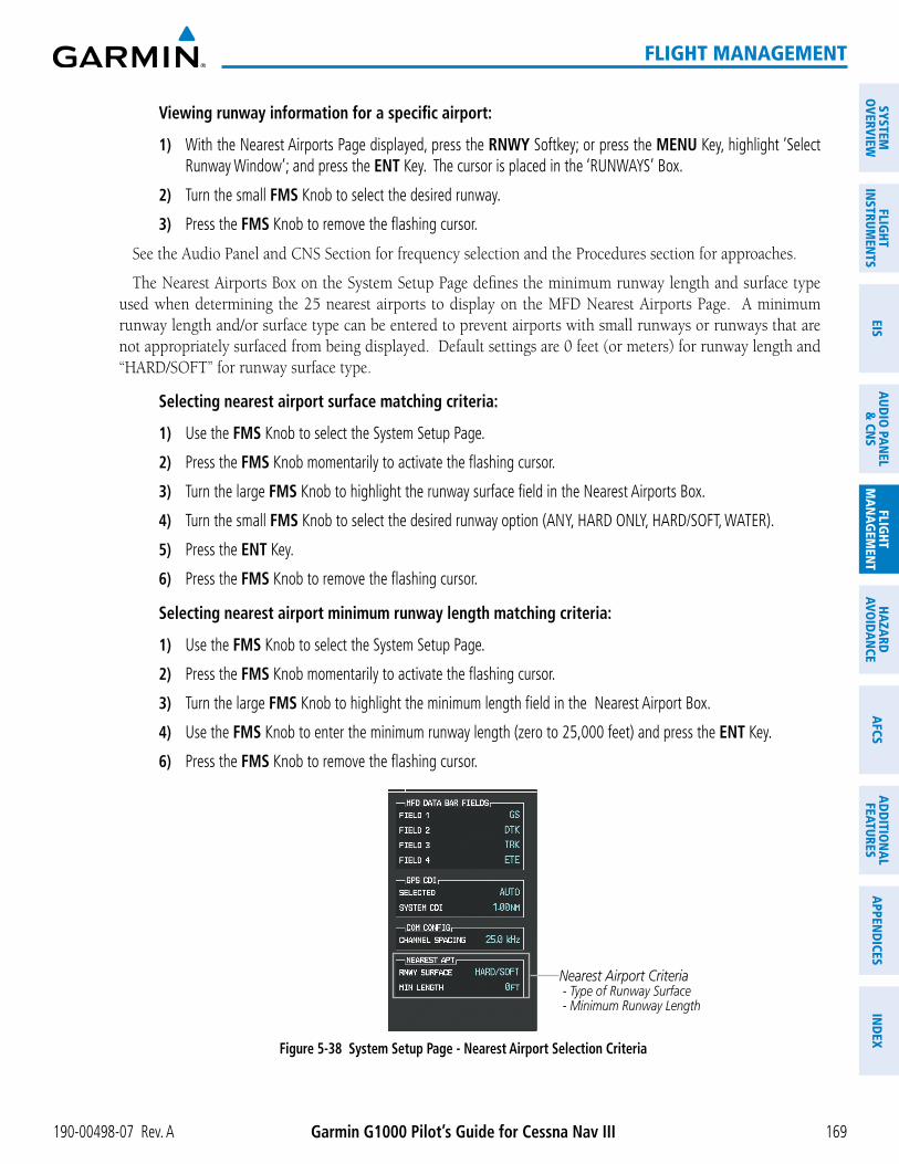
Viewing runway information for a specific airport:
1) With the Nearest Airports Page displayed, press the RNWY Softkey; or press the MENU Key, highlight ‘Select Runway Window’; and press the ENT Key. The cursor is placed in the ‘RUNWAYS’ Box.
2) Turn the small FMS Knob to select the desired runway.
3) Press the FMS Knob to remove the flashing cursor.
The Nearest Airports Box on the System Setup Page defines the minimum runway length and surface type used when determining the 25 nearest airports to display on the MFD Nearest Airports Page. A minimum runway length and/or surface type can be entered to prevent airports with small runways or runways that are not appropriately surfaced from being displayed. Default settings are 0 feet (or meters) for runway length and “HARD/SOFT” for runway surface type.
Selecting nearest airport surface matching criteria:
1) Use the FMS Knob to select the System Setup Page.
2) Press the FMS Knob momentarily to activate the flashing cursor.
3) Turn the large FMS Knob to highlight the runway surface field in the Nearest Airports Box.
4) Turn the small FMS Knob to select the desired runway option (ANY, HARD ONLY, HARD/SOFT, WATER).
5) Press the ENT Key.
6) Press the FMS Knob to remove the flashing cursor.
Selecting nearest airport minimum runway length matching criteria:
1) Use the FMS Knob to select the System Setup Page.
2) Press the FMS Knob momentarily to activate the flashing cursor.
3) Turn the large FMS Knob to highlight the minimum length field in the Nearest Airport Box.
4) Use the FMS Knob to enter the minimum runway length (zero to 25,000 feet) and press the ENT Key.
6) Press the FMS Knob to remove the flashing cursor.
Figure 5-38 System Setup Page - Nearest Airport Selection Criteria
Nearest Airport Criteria - Type of Runway Surface - Minimum Runway Length

Garmin G1000 Pilot’s Guide for Cessna Nav III 190-00498-07 Rev. A170
FLIGHT MANAGEMENT
SYST
EMO
VERV
IEW
FLIG
HTIN
STRU
MEN
TSEI
SAU
DIO
PAN
EL&
CN
SFL
IGHT
MAN
AGEM
ENT
HAZA
RDAV
OID
ANCE
AFCS
ADD
ITIO
NAL
FEAT
URES
APPE
ND
ICES
IND
EX
INTERSECTIONS
NOTE: The VOR displayed on the Intersection Information Page is the nearest VOR, not necessarily the VOR used to define the intersection.
The Intersection Information Page is used to view information about intersections. In addition to displaying a map of the currently selected intersection and surrounding area, the Intersection Information Page displays
Figure 5-39 Intersection Information Page
Selected Intersection
Navigation MapShowing Selected
Intersection
Intersection Identifier
Nearest VOR Info - Identifier/Type (symbol) - Radial to VOR - Distance to VOR
Intersection Info - Region - Lat/Long
Selecting an intersection:
1) With the Intersection Information Page displayed, enter an identifier in the Intersection Box.
2) Press the ENT Key.
3) Press the FMS Knob to remove the flashing cursor.
Or:
1) With the Nearest Intersections Page displayed, press the FMS Knob.
2) Press the ENT Key or turn either FMS Knob to select an identifier in the Nearest Intersection Box.
3) Press the FMS Knob to remove the flashing cursor.

190-00498-07 Rev. A Garmin G1000 Pilot’s Guide for Cessna Nav III 171
FLIGHT MANAGEMENT
SYSTEMO
VERVIEWFLIG
HTIN
STRUMEN
TSEIS
AUDIO
PANEL
& CN
SFLIG
HTM
ANAG
EMEN
THAZARD
AVOIDAN
CEAFCS
ADD
ITION
ALFEATURES
APPEND
ICESIN
DEX
to displaying a map of the surrounding area, the page displays information for up to 25 nearest intersections in
The selected intersection is indicated by a white arrow. Up to eleven Intersections are visible at a time. If there are more than can be shown, the list can be scrolled. If there are no items for display, text indicating that fact is displayed.
NOTE: The list only includes waypoints that are within 200 nm.
Figure 5-40 Nearest Intersections Page
Nearest Intersection
Navigation MapShowing Nearest
Intersection
Intersection Information - Identifier/Symbol - Bearing/Distance to intersection from aircraft position
Reference VOR Info - Identifier/Type (symbol) - VOR Frequency - Bearing/Distance to VOR
Intersection Lat/Long

Garmin G1000 Pilot’s Guide for Cessna Nav III 190-00498-07 Rev. A172
FLIGHT MANAGEMENT
SYST
EMO
VERV
IEW
FLIG
HTIN
STRU
MEN
TSEI
SAU
DIO
PAN
EL&
CN
SFL
IGHT
MAN
AGEM
ENT
HAZA
RDAV
OID
ANCE
AFCS
ADD
ITIO
NAL
FEAT
URES
APPE
ND
ICES
IND
EX
NDBS
The NDB Information Page is used to view information about NDBs. In addition to displaying a map of the currently selected NDB and surrounding area, the page displays NDB information in four boxes labeled
Figure 5-41 NDB Information Page
Selected NDB
Navigation MapShowing Selected
NDB
NDB Identifier/Type - Facility Name - Nearest City
Nearest Airport Info - Identifier/Type (symbol) - Bearing/Distance to Airport
NDB Information - Type - Region - Lat/Long
NDB Frequency
NOTE: Compass locator (LOM, LMM): a low power, low or medium frequency radio beacon installed in conjunction with the instrument landing system. When LOM is used, the locator is at the Outer Marker; when LMM is used, the locator is at the Middle Marker.
Selecting an NDB:
1) With the NDB Information Page displayed, enter an identifier, the name of the NDB, or the city in which it’s located in the NDB Box.
2) Press the ENT Key.
3) Press the FMS Knob to remove the flashing cursor.
Or:
1) With the Nearest NDB Page displayed, press the FMS Knob.
2) Press the ENT Key or turn either FMS Knob to select an identifier in the Nearest NDB Box.
3) Press the FMS Knob to remove the flashing cursor.

190-00498-07 Rev. A Garmin G1000 Pilot’s Guide for Cessna Nav III 173
FLIGHT MANAGEMENT
SYSTEMO
VERVIEWFLIG
HTIN
STRUMEN
TSEIS
AUDIO
PANEL
& CN
SFLIG
HTM
ANAG
EMEN
THAZARD
AVOIDAN
CEAFCS
ADD
ITION
ALFEATURES
APPEND
ICESIN
DEX
a map of the surrounding area, the page displays information for up to 25 nearest NDBs in three boxes labeled
A white arrow before the NDB identifier indicates the selected NDB. Up to eleven NDBs are visible at a time. If there are more than can be shown, each list can be scrolled. The list only includes waypoints that are within 200nm. If there are no NDBs in the list, text indicating that there are no nearest NDBs is displayed. If there are
Figure 5-42 Nearest NDB Page
Nearest NDB
Navigation MapShowing Selected
NDB
NDB Information - Facility Name/City - Type - Lat/Long
NDB Identifier/Symbol - Bearing/Distance to NDB from aircraft position
NDB Frequency

Garmin G1000 Pilot’s Guide for Cessna Nav III 190-00498-07 Rev. A174
FLIGHT MANAGEMENT
SYST
EMO
VERV
IEW
FLIG
HTIN
STRU
MEN
TSEI
SAU
DIO
PAN
EL&
CN
SFL
IGHT
MAN
AGEM
ENT
HAZA
RDAV
OID
ANCE
AFCS
ADD
ITIO
NAL
FEAT
URES
APPE
ND
ICES
IND
EX
VORS
The VOR Information Page can be used to view information about VOR and ILS signals (since ILS signals
cannot be viewed on the VOR Information Page. If a VOR station is combined with a TACAN station it is listed as a VORTAC on the VOR Information Page and if it includes only DME, it is displayed as VOR-DME.
In addition to displaying a map of the currently selected VOR and surrounding area, the VOR Information
AIRPORT’.
Figure 5-43 VOR Information Page
Selected VOR
Navigation MapShowing Selected
VOR
VOR Identifier/Type - Facility Name - Nearest City
Nearest Airport Info - Identifier/Type (symbol) - Bearing/Distance to Airport
VOR Information - Class/Magnetic Variation - Region - Lat/Long
VOR Frequency
The VOR classes used in the VOR information box are: LOW ALTITUDE, HIGH ALTITUDE, and TERMINAL.
Select a VOR:
1) With the VOR Information Page displayed, enter an identifier, the name of the VOR, or the city in which it’s located in the VOR Box.
2) Press the ENT Key.
3) Press the FMS Knob to remove the flashing cursor.
Or:
1) With the Nearest VOR Page displayed, press the FMS Knob or press the VOR Softkey.
2) Press the ENT Key or turn either FMS Knob to select an identifier in the Nearest VOR Box.
3) Press the FMS Knob to remove the flashing cursor.
Or:

190-00498-07 Rev. A Garmin G1000 Pilot’s Guide for Cessna Nav III 175
FLIGHT MANAGEMENT
SYSTEMO
VERVIEWFLIG
HTIN
STRUMEN
TSEIS
AUDIO
PANEL
& CN
SFLIG
HTM
ANAG
EMEN
THAZARD
AVOIDAN
CEAFCS
ADD
ITION
ALFEATURES
APPEND
ICESIN
DEX
1) With the Nearest VOR Page displayed, press the MENU Key.
2) Highlight ‘Select VOR Window’, and press the ENT Key.
3) Press the ENT Key or turn either FMS Knob to select an identifier in the Nearest VOR Box.
4) Press the FMS Knob to remove the flashing cursor.
from a selected VOR station can be loaded from the Nearest VOR Page. In addition to displaying a map of the surrounding area, the Nearest VOR Page displays information for up to 25 nearest VOR stations in three
are within 200 nm.
A white arrow before the VOR identifier indicates the selected VOR. Up to eleven VORs are visible at a time. If there are more than can be shown, each list can be scrolled. If there are no VORs in the list, text indicating that there are no nearest VORs is displayed. If there are no nearest VORs in the list, the information is dashed.
Figure 5-44 Nearest VOR Page
Nearest VOR
Navigation MapShowing Nearest
VOR
VOR Information - Facility Name/City - Class/Magnetic Variation - Lat/Long
VOR Identifier/Symbol - Bearing/Distance to VOR from aircraft position
VOR Frequency

Garmin G1000 Pilot’s Guide for Cessna Nav III 190-00498-07 Rev. A176
FLIGHT MANAGEMENT
SYST
EMO
VERV
IEW
FLIG
HTIN
STRU
MEN
TSEI
SAU
DIO
PAN
EL&
CN
SFL
IGHT
MAN
AGEM
ENT
HAZA
RDAV
OID
ANCE
AFCS
ADD
ITIO
NAL
FEAT
URES
APPE
ND
ICES
IND
EX
USER WAYPOINTSThe G1000 can create and store up to 1,000 user-defined waypoints. User waypoints can be created from any
map using the Joystick, or from the User Waypoint Information Page by referencing a bearing/distance from an existing waypoint, bearings from two existing waypoints, or latitude and longitude. Once a waypoint has been created, it can be renamed, deleted, or moved. Temporary user waypoints are erased upon system power down.
Figure 5-45 User Waypoint Information Page
Selected User Waypoint
Navigation MapShowing Selected
User Waypoint
User Waypoint List - Identifier - Comment
Softkeys
# User Wpts Used
GO BACK displayed if User Wpt was created on map page
User Wpt Comment
User Waypoint Info - Identifier - Temporary/Normal - Waypoint Type
Reference Wpt/Info - Identifier/Rad/Dist or - Identifiers/Radials or - Region/Lat/Long
Selecting a User Waypoint:
1) With the User Waypoint Information Page displayed, enter the name of the User Waypoint, or scroll to the desired waypoint in the User Waypoint List using the large FMS Knob.
2) Press the ENT Key.
3) Press the FMS Knob to remove the flashing cursor.
Or:
1) With the Nearest User Waypoints Page displayed, press the FMS Knob.
2) Press the ENT Key or turn either FMS Knob to select an identifier in the Nearest USR Box.
3) Press the FMS Knob to remove the flashing cursor.

190-00498-07 Rev. A Garmin G1000 Pilot’s Guide for Cessna Nav III 177
FLIGHT MANAGEMENT
SYSTEMO
VERVIEWFLIG
HTIN
STRUMEN
TSEIS
AUDIO
PANEL
& CN
SFLIG
HTM
ANAG
EMEN
THAZARD
AVOIDAN
CEAFCS
ADD
ITION
ALFEATURES
APPEND
ICESIN
DEX
Figure 5-46 Nearest User Waypoint Page
Selected User Waypoint
Navigation MapShowing Selected
User Waypoint
Nearest User Wpt List - Identifier - Bearing/Distance from aircraft position
User Waypoint Info - Comment - Lat/Long
Reference Wpt Info - Identifier - Radial/Distance
CREATING USER WAYPOINTSUser waypoints can be created from the User Waypoint Information Page in the following ways:
Creating user waypoints from the User Waypoint Information Page:
1) Select the NEW Softkey, or press the MENU Key and select ‘Create New User Waypoint’.
2) Enter a user waypoint name (up to six characters).
3) Press the ENT Key. The current aircraft position is the default location of the new waypoint.
4) If desired, define the type and location of the waypoint in one of the following ways:
a) Select “RAD/RAD” using the small FMS Knob, press the ENT Key, and enter the two reference waypoint identifiers and radials into the REFERENCE WAYPOINTS window using the FMS Knobs.
Or:
b) Select “RAD/DIS” using the small FMS Knob, press the ENT Key, and enter the reference waypoint identifier, the radial, and the distance into the REFERENCE WAYPOINTS window using the FMS Knobs.
Or:
c) Select “LAT/LON” using the small FMS Knob, press the ENT Key, and enter the latitude and longitude into the INFORMATION window using the FMS Knobs.
5) Press the ENT Key to accept the new waypoint.
6) If desired, change the storage method of the waypoint to “TEMPORARY” or “NORMAL” by moving the cursor to “TEMPORARY” and selecting the ENT Key to check or uncheck the box.
7) Press the FMS Knob to remove the flashing cursor.
Or:

Garmin G1000 Pilot’s Guide for Cessna Nav III 190-00498-07 Rev. A178
FLIGHT MANAGEMENT
SYST
EMO
VERV
IEW
FLIG
HTIN
STRU
MEN
TSEI
SAU
DIO
PAN
EL&
CN
SFL
IGHT
MAN
AGEM
ENT
HAZA
RDAV
OID
ANCE
AFCS
ADD
ITIO
NAL
FEAT
URES
APPE
ND
ICES
IND
EX
1) Press the FMS Knob to activate the cursor.
2) Enter a user waypoint name (up to six characters).
3) Press the ENT Key. The message ‘Are you sure you want to create the new User Waypoint AAAAAA?’ is displayed.
4) With ‘YES’ highlighted, press the ENT Key.
5) If desired, define the type and location of the waypoint in one of the following ways:
a) Select “RAD/RAD” using the small FMS Knob, press the ENT Key, and enter the two reference waypoint identifiers and radials into the REFERENCE WAYPOINTS window using the FMS Knobs.
Or:
b) Select “RAD/DIS” using the small FMS Knob, press the ENT Key, and enter the reference waypoint identifier, the radial, and the distance into the REFERENCE WAYPOINTS window using the FMS Knobs.
Or:
c) Select “LAT/LON” using the small FMS Knob, press the ENT Key, and enter the latitude and longitude into the INFORMATION window using the FMS Knobs.
6) Press the ENT Key to accept the new waypoint.
7) If desired, change the storage method of the waypoint to “TEMPORARY” or “NORMAL” by moving the cursor to “TEMPORARY” and selecting the ENT Key to check or uncheck the box.
8) Press the FMS Knob to remove the flashing cursor.
Figure 5-47 User Waypoint Information Page Menu
Creating user waypoints from map pages:
1) Press the Joystick to activate the panning function and pan to the map location of the desired user waypoint.
2) Press the ENT Key. The User Waypoint Information Page is displayed with the captured position.
NOTE: If the pointer has highlighted a map database feature, one of three things happens upon pressing the ENT Key: 1) information about the selected feature is displayed instead of initiating a new waypoint, 2) a menu pops up allowing a choice between ‘Review Airspaces’ or ‘Create User Waypoint’, or 3) a new waypoint is initiated with the default name being the selected map item.

190-00498-07 Rev. A Garmin G1000 Pilot’s Guide for Cessna Nav III 179
FLIGHT MANAGEMENT
SYSTEMO
VERVIEWFLIG
HTIN
STRUMEN
TSEIS
AUDIO
PANEL
& CN
SFLIG
HTM
ANAG
EMEN
THAZARD
AVOIDAN
CEAFCS
ADD
ITION
ALFEATURES
APPEND
ICESIN
DEX
3) Enter a user waypoint name (up to six characters).
4) Press the ENT Key to accept the selected name. The first reference waypoint box is highlighted.
5) If desired, define the type and location of the waypoint in one of the following ways:
a) Select “RAD/RAD” using the small FMS Knob, press the ENT Key, and enter the two reference waypoint identifiers and radials into the REFERENCE WAYPOINTS window using the FMS Knobs.
Or:
b) Select “RAD/DIS” using the small FMS Knob, press the ENT Key, and enter the reference waypoint identifier, the radial, and the distance into the REFERENCE WAYPOINTS window using the FMS Knobs.
Or:
c) Select “LAT/LON” using the small FMS Knob, press the ENT Key, and enter the latitude and longitude into the INFORMATION window using the FMS Knobs.
6) Press the ENT Key to accept the new waypoint.
7) If desired, change the storage method of the waypoint to “TEMPORARY” or “NORMAL” by moving the cursor to “TEMPORARY” and selecting the ENT Key to check or uncheck the box.
8) Press the FMS Knob to remove the flashing cursor.
9) Press the GO BACK Softkey to return to the map page.
EDITING USER WAYPOINTS
Editing a user waypoint comment or location:
1) With the User Waypoint Information Page displayed, press the FMS Knob to activate the cursor.
2) Select a user waypoint in the User Waypoint List, if required, and press the ENT Key.
3) Move the cursor to the desired field.
4) Turn the small FMS Knob to make any changes.
5) Press the ENT Key to accept the changes.
6) Press the FMS Knob to remove the flashing cursor.
Renaming user waypoints:
1) Highlight a user waypoint in the User Waypoint List. Press the RENAME Softkey, or press the MENU Key and select ‘Rename User Waypoint’.
2) Enter a new name.
3) Press the ENT Key. The message ‘Do you want to rename the user waypoint AAAAAA to BBBBBB?’ is displayed.
4) With ‘YES’ highlighted, press the ENT Key.
5) Press the FMS Knob to remove the flashing cursor.

Garmin G1000 Pilot’s Guide for Cessna Nav III 190-00498-07 Rev. A180
FLIGHT MANAGEMENT
SYST
EMO
VERV
IEW
FLIG
HTIN
STRU
MEN
TSEI
SAU
DIO
PAN
EL&
CN
SFL
IGHT
MAN
AGEM
ENT
HAZA
RDAV
OID
ANCE
AFCS
ADD
ITIO
NAL
FEAT
URES
APPE
ND
ICES
IND
EX
Changing the location of an existing waypoint to the aircraft present position:
1) Enter a waypoint name or select the waypoint in the User Waypoint List, then press the ENT Key.
2) Press the MENU Key.
3) Select ‘Use Present Position’.
4) Press the ENT Key twice. The new waypoint’s location is saved.
5) Press the FMS Knob to remove the flashing cursor.
A system generated comment for a user waypoint incorporates the reference waypoint identifier, bearing, and distance. If a system generated comment has been edited, a new comment can be generated.
Resetting the comment field to the system generated comment:
1) Enter a waypoint name or select the waypoint in the User Waypoint List, then press the ENT Key.
2) Press the MENU Key.
3) Select ‘Auto Comment’.
4) Press the ENT Key. The generated comment is based on the reference point used to define the waypoint.
The default type of user waypoint (normal or temporary) can be changed using the user waypoint information page menu. Temporary user waypoints are automatically deleted upon the next power cycle.
Changing the user waypoint storage duration default setting:
1) With the User Waypoint Information Page displayed, press the MENU Key.
2) Move the cursor to select ‘Waypoint Setup’, and press the ENT Key.
3) Select ‘NORMAL’ or ‘TEMPORARY’ as desired, and press the ENT Key.
4) Press the FMS Knob to remove the flashing cursor and return to the User Waypoint Information Page.

190-00498-07 Rev. A Garmin G1000 Pilot’s Guide for Cessna Nav III 181
FLIGHT MANAGEMENT
SYSTEMO
VERVIEWFLIG
HTIN
STRUMEN
TSEIS
AUDIO
PANEL
& CN
SFLIG
HTM
ANAG
EMEN
THAZARD
AVOIDAN
CEAFCS
ADD
ITION
ALFEATURES
APPEND
ICESIN
DEX
DELETING USER WAYPOINTS
Deleting a single user waypoint:
1) Highlight a User Waypoint in the User Waypoint List, or enter a waypoint in the User Waypoint field.
2) Press the DELETE Softkey or press the CLR Key. ‘Yes’ is highlighted in the confirmation window.
3) Press the ENT Key.
4) Press the FMS Knob to remove the flashing cursor.
Or:
1) Highlight a User Waypoint in the User Waypoint List, or enter a waypoint in the User Waypoint field.
2) Press the MENU Key.
3) Select ‘Delete User Waypoint’.
4) Press the ENT Key twice to confirm the selection.
5) Press the FMS Knob to remove the flashing cursor.
NOTE: The option to ‘Delete All User Waypoints’ is not available while the aircraft is in flight.
Deleting all user waypoints:
1) Highlight a User Waypoint in the User Waypoint List.
2) Press the MENU Key.
3) Select ‘Delete All User Waypoints’.
4) Press the ENT Key twice to confirm the selection.
5) Press the FMS Knob to remove the flashing cursor.

Garmin G1000 Pilot’s Guide for Cessna Nav III 190-00498-07 Rev. A182
FLIGHT MANAGEMENT
SYST
EMO
VERV
IEW
FLIG
HTIN
STRU
MEN
TSEI
SAU
DIO
PAN
EL&
CN
SFL
IGHT
MAN
AGEM
ENT
HAZA
RDAV
OID
ANCE
AFCS
ADD
ITIO
NAL
FEAT
URES
APPE
ND
ICES
IND
EX
5.4 AIRSPACES
The G1000 can display the following types of airspaces: Class B/TMA, Class C/TCA, Class D, Restricted, MOA (Military), Other Airspace, Air Defense Interdiction Zone (ADIZ), and Temporary Flight Restriction (TFR).
Figure 5-48 Airspaces
MOA (Military) Class D Airspace
Class B Airspace
Restricted Area
Class C Airspace Alert Area
ADIZ
Warning Area
The Nearest Airspaces Page, Airspace Alerts Window, and Airspace Alerts on the PFD provide additional information about airspaces and the location of the aircraft in relationship to them.
The Airspace Alerts Box allows the pilot to turn the controlled/special-use airspace message alerts on or off. This does not affect the alerts listed on the Nearest Airspaces Page or the airspace boundaries depicted on the Navigation Map Page. It simply turns on/off the warning provided when the aircraft is approaching or near an airspace.

190-00498-07 Rev. A Garmin G1000 Pilot’s Guide for Cessna Nav III 183
FLIGHT MANAGEMENT
SYSTEMO
VERVIEWFLIG
HTIN
STRUMEN
TSEIS
AUDIO
PANEL
& CN
SFLIG
HTM
ANAG
EMEN
THAZARD
AVOIDAN
CEAFCS
ADD
ITION
ALFEATURES
APPEND
ICESIN
DEX
An altitude buffer is also provided which “expands” the vertical range above or below an airspace. For example, if the buffer is set at 500 feet, and the aircraft is more than 500 feet above/below an airspace, an alert message is not generated, but if the aircraft is less than 500 feet above/below an airspace and projected to enter it, the pilot is notified with an alert message. The default setting for the altitude buffer is 200 feet.
Changing the altitude buffer distance setting:
1) Use the FMS Knob to select the AUX - System Setup Page.
2) Press the FMS Knob momentarily to activate the flashing cursor.
3) Turn the large FMS Knob to highlight the altitude buffer field in the Airspace Alerts Box.
4) Use the FMS Knob to enter an altitude buffer value and press the ENT Key.
5) Press the FMS Knob to remove the flashing cursor.
Turning an airspace alert on or off:
1) Use the FMS Knob to select the AUX - System Setup Page.
2) Press the FMS Knob momentarily to activate the flashing cursor.
3) Turn the large FMS Knob to highlight the desired field in the Airspace Alerts Box.
4) Turn the small FMS Knob clockwise to turn the airspace alert ON or counterclockwise to turn the alert OFF.
5) Press the FMS Knob to remove the flashing cursor.
Figure 5-49 System Setup Page - Airspace AlertsDFLTS Softkey
Airspace Alerts Box - Airspace Altitude Buffer - Alert On/Off (Default Settings Shown)
Map ranges for the airspace boundaries are selected from the Aviation Group in the Map Setup Menu. See Table 5-2 for the default and maximum ranges for each type of airspace and the symbol defining the airspace area.
a map of airspace boundaries and surrounding area, the Nearest Airspaces Page displays airspace information in
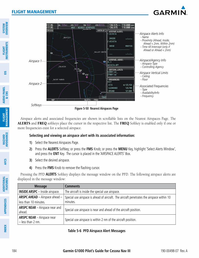
Garmin G1000 Pilot’s Guide for Cessna Nav III 190-00498-07 Rev. A184
FLIGHT MANAGEMENT
SYST
EMO
VERV
IEW
FLIG
HTIN
STRU
MEN
TSEI
SAU
DIO
PAN
EL&
CN
SFL
IGHT
MAN
AGEM
ENT
HAZA
RDAV
OID
ANCE
AFCS
ADD
ITIO
NAL
FEAT
URES
APPE
ND
ICES
IND
EX
Figure 5-50 Nearest Airspaces Page
Airspace Alerts Info - Name - Proximity (Ahead, Inside, Ahead < 2nm, Within 2nm) - Time till Intercept (only if Ahead or Ahead < 2nm)
Airspace Vertical Limits - Ceiling - Floor
Airspace/Agency Info - Airspace Type - Controlling Agency
Softkeys
Airspace 1
Associated Frequencies - Type - Availability/Info - Frequency
Airspace 2
ALERTS and FREQ softkeys place the cursor in the respective list. The FREQ Softkey is enabled only if one or
Selecting and viewing an airspace alert with its associated information:
1) Select the Nearest Airspaces Page.
2) Press the ALERTS Softkey; or press the FMS Knob; or press the MENU Key, highlight ‘Select Alerts Window’, and press the ENT Key. The cursor is placed in the ‘AIRSPACE ALERTS’ Box.
3) Select the desired airspace.
4) Press the FMS Knob to remove the flashing cursor.
Pressing the PFD ALERTS Softkey displays the message window on the PFD. The following airspace alerts are displayed in the message window:
Message CommentsINSIDE ARSPC – Inside airspace. The aircraft is inside the special use airspace.ARSPC AHEAD – Airspace ahead – less than 10 minutes.
Special use airspace is ahead of aircraft. The aircraft penetrates the airspace within 10 minutes.
ARSPC NEAR – Airspace near and ahead. Special use airspace is near and ahead of the aircraft position.
ARSPC NEAR – Airspace near – less than 2 nm. Special use airspace is within 2 nm of the aircraft position.
Table 5-6 PFD Airspace Alert Messages

190-00498-07 Rev. A Garmin G1000 Pilot’s Guide for Cessna Nav III 185
FLIGHT MANAGEMENT
SYSTEMO
VERVIEWFLIG
HTIN
STRUMEN
TSEIS
AUDIO
PANEL
& CN
SFLIG
HTM
ANAG
EMEN
THAZARD
AVOIDAN
CEAFCS
ADD
ITION
ALFEATURES
APPEND
ICESIN
DEX
5.5 DIRECT-TO-NAVIGATION
The Direct-to method of navigation, initiated by pressing the Direct-to Key on either the MFD or PFD, is
Once a direct-to is activated, the G1000 establishes a point-to-point course line from the present position to the selected direct-to destination. Course guidance is provided until the direct-to is replaced with a new direct-to or flight plan, or cancelled.
A vertical navigation (VNV) direct-to creates a descent path (and provides guidance to stay on the path) from the current altitude to a selected altitude at the direct-to waypoint. Vertical navigation is based on barometric altitudes, not on GPS altitude, and is used for cruise and descent phases of flight.
The Direct-to Window allows selection and activation of direct-to navigation. The Direct-to Window displays selected direct-to waypoint data on the PFD and the MFD.
Figure 5-51 Direct-to Window - MFD
Direct-to Point Info - Identifier/Symbol/Region - Facility Name - City
Location of Destination - Bearing/Distance
Map of Selected Point
Desired Course
VNV Constraints- Altitude at Arrival
- Along Track Offset
Figure 5-52 Direct-to Window - PFD
Direct-to Point Info - Identifier/Symbol/City - Facility Name
Activation Command
Direct-to Point Info - Bearing/Distance - Desired Course
VNV Constraints- Altitude at Arrival
- Along Track Offset

Garmin G1000 Pilot’s Guide for Cessna Nav III 190-00498-07 Rev. A186
FLIGHT MANAGEMENT
SYST
EMO
VERV
IEW
FLIG
HTIN
STRU
MEN
TSEI
SAU
DIO
PAN
EL&
CN
SFL
IGHT
MAN
AGEM
ENT
HAZA
RDAV
OID
ANCE
AFCS
ADD
ITIO
NAL
FEAT
URES
APPE
ND
ICES
IND
EX
Any waypoint can be entered as a direct-to destination from the Direct-to Window.
Entering a waypoint identifier, facility name, or city as a direct-to destination:
1) Press the Direct-to Key. The Direct-to Window is displayed (with the active flight plan wayoint as the default selection or a blank waypoint field if no flight plan is active).
2) Turn the small FMS Knob clockwise to begin entering a waypoint identifier (turning it counter-clockwise brings up the waypoint selection submenu - press the CLR Key to remove it), or turn the large FMS Knob to select the facility name, or city field and turn the small FMS Knob to begin entering a facility name or city. If duplicate entries exist for the entered facility or city name, additional entries can be viewed by turning the small FMS Knob during the selection process.
3) Press the ENT Key. The ‘Activate?’ field is highlighted.
4) Press the ENT Key to activate the direct-to.
Any waypoint contained in the active flight plan can be selected as a direct-to waypoint from the Direct-to Window, the Active Flight Plan Page, or the Active Flight Plan Window.
Figure 5-53 Waypoint Submenu
Waypoint Submenu - Flight Plan Waypoints - Nearest Airports - Recent Waypoints - User Waypoints - Airway Waypoints (only available when active leg is part of an airway)
Selecting an active flight plan waypoint as a direct-to destination:
1) While navigating an active flight plan, press the Direct-to Key. The Direct-to Window is displayed with the active flight plan waypoint as the default selection.
2) Turn the small FMS Knob counter-clockwise to display a list of flight plan waypoints (the FPL list is populated only when navigating a flight plan).
3) Select the desired waypoint.
4) Press the ENT Key. The cursor is now displayed on ‘ACTIVATE?’.
5) Press the ENT Key again to activate the direct-to.
Or:
1) Select the Active Flight Plan Page on the MFD, or the Active Flight Plan Window on the PFD.
2) Select the desired waypoint.
3) Press the Direct-to Key.
4) Press the ENT Key. The cursor is now displayed on ‘ACTIVATE?’.
5) Press the ENT Key again to activate the direct-to.

190-00498-07 Rev. A Garmin G1000 Pilot’s Guide for Cessna Nav III 187
FLIGHT MANAGEMENT
SYSTEMO
VERVIEWFLIG
HTIN
STRUMEN
TSEIS
AUDIO
PANEL
& CN
SFLIG
HTM
ANAG
EMEN
THAZARD
AVOIDAN
CEAFCS
ADD
ITION
ALFEATURES
APPEND
ICESIN
DEX
direct-to destination in the Direct-to Window.
Selecting a NRST, RECENT, USER, or AIRWAY waypoint as a direct-to destination:
1) Press the Direct-to Key. The Direct-to Window is displayed (with the active flight plan destination as the default selection or a blank destination if no flight plan is active).
2) Turn the small FMS Knob counter-clockwise to display a list of FPL waypoints (the FPL list is populated only when navigating a flight plan, and the AIRWAY list is available only when the active leg is part of an airway).
3) Turn the small FMS Knob clockwise to display the NRST, RECENT, USER, or AIRWAY waypoints.
4) Turn the large FMS Knob clockwise to select the desired waypoint.
5) Press the ENT Key. The cursor is now displayed on ‘ACTIVATE?’.
6) Press the ENT Key again to activate the direct-to.
The Direct-to Window can be displayed from any page and allows selection and activation of direct-to navigation. If the direct-to is initiated from any page except the WPT pages, the default waypoint is the active flight plan
displayed waypoint.
Selecting any waypoint as a direct-to destination:
1) Select the page or window containing the desired waypoint type and select the desired waypoint.
2) Press the Direct-to Key to display the Direct-to Window with the selected waypoint as the direct-to destination.
3) Press the ENT Key. The cursor is now displayed on ‘ACTIVATE?’.
4) Press ENT again to activate the direct-to.
Selecting a nearby airport as a direct-to destination:
1) Press the NRST Softkey on the PFD; or turn the FMS Knob to display the Nearest Airports Page and press the FMS Knob.
2) Select the desired airport (the nearest one is already selected).
3) Press the Direct-to Key.
4) Press the ENT Key. The cursor is now displayed on ‘ACTIVATE?’.
5) Press the ENT Key again to activate the direct-to.
Direct-to destinations may also be selected by using the pointer on the navigation map pages. If no airport,
created at the location of the map arrow.
Selecting a waypoint as a direct-to destination using the pointer:
1) From a navigation map page, press the Joystick to display the pointer.
2) Move the Joystick to place the pointer at the desired destination location.
3) If the pointer is placed on an existing airport, NAVAID, or user waypoint, the waypoint name is highlighted.
4) Press the Direct-to Key to display the Direct-to Window with the selected point entered as the direct-to destination.
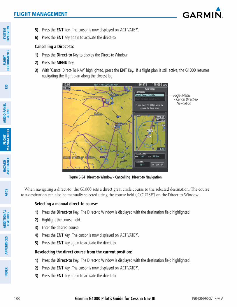
Garmin G1000 Pilot’s Guide for Cessna Nav III 190-00498-07 Rev. A188
FLIGHT MANAGEMENT
SYST
EMO
VERV
IEW
FLIG
HTIN
STRU
MEN
TSEI
SAU
DIO
PAN
EL&
CN
SFL
IGHT
MAN
AGEM
ENT
HAZA
RDAV
OID
ANCE
AFCS
ADD
ITIO
NAL
FEAT
URES
APPE
ND
ICES
IND
EX
5) Press the ENT Key. The cursor is now displayed on ‘ACTIVATE?’.
6) Press the ENT Key again to activate the direct-to.
Cancelling a Direct-to:
1) Press the Direct-to Key to display the Direct-to Window.
2) Press the MENU Key.
3) With ‘Cancel Direct-To NAV’ highlighted, press the ENT Key. If a flight plan is still active, the G1000 resumes navigating the flight plan along the closest leg.
Figure 5-54 Direct-to Window - Cancelling Direct-to Navigation
Page Menu - Cancel Direct-To Navigation
When navigating a direct-to, the G1000 sets a direct great circle course to the selected destination. The course
Selecting a manual direct-to course:
1) Press the Direct-to Key. The Direct-to Window is displayed with the destination field highlighted.
2) Highlight the course field.
3) Enter the desired course.
4) Press the ENT Key. The cursor is now displayed on ‘ACTIVATE?’.
5) Press the ENT Key again to activate the direct-to.
Reselecting the direct course from the current position:
1) Press the Direct-to Key. The Direct-to Window is displayed with the destination field highlighted.
2) Press the ENT Key. The cursor is now displayed on ‘ACTIVATE?’.
3) Press the ENT Key again to activate the direct-to.

190-00498-07 Rev. A Garmin G1000 Pilot’s Guide for Cessna Nav III 189
FLIGHT MANAGEMENT
SYSTEMO
VERVIEWFLIG
HTIN
STRUMEN
TSEIS
AUDIO
PANEL
& CN
SFLIG
HTM
ANAG
EMEN
THAZARD
AVOIDAN
CEAFCS
ADD
ITION
ALFEATURES
APPEND
ICESIN
DEX
A direct-to with altitude constraints creates a descent path (and provides guidance to stay on the path) from the aircraft’s current altitude to the altitude of the direct-to waypoint. The altitude is reached at the waypoint, or at the specified distance along the flight path if an offset distance has been entered. All VNV altitudes prior to the direct-to destination are removed from the active flight plan upon successful activation of the direct-to. All VNV altitudes following the direct-to waypoint are retained. See the section on Vertical Navigation for more information regarding the use and purpose of VNV altitudes and offset distances.
Entering a VNV altitude and along-track offset for the waypoint:
1) Press the Direct-to Key to display the Direct-to Window.
2) Turn the large FMS Knob to place the cursor over the ‘VNV’ altitude field.
3) Enter the desired altitude.
4) Press the ENT Key. The option to select MSL or AGL is now displayed.
5) Turn the small FMS Knob to select ‘MSL’ or ‘AGL’.
6) Press the ENT Key. The cursor is now flashing in the VNV offset distance field.
7) Enter the desired along-track distance before the waypoint.
8) Press the ENT Key. The ‘Activate?’ field is highlighted.
9) Press the ENT Key to activate.
Removing a VNV altitude constraint:
1) Press the Direct-to Key to display the Direct-to Window.
2) Press the MENU Key.
3) With ‘Clear Vertical Constraints’ highlighted, press the ENT Key.
Figure 5-55 Direct-to Window - Clearing Vertical Constraints
Page Menu - Clear Vertical Navigation Constraints

Garmin G1000 Pilot’s Guide for Cessna Nav III 190-00498-07 Rev. A190
FLIGHT MANAGEMENT
SYST
EMO
VERV
IEW
FLIG
HTIN
STRU
MEN
TSEI
SAU
DIO
PAN
EL&
CN
SFL
IGHT
MAN
AGEM
ENT
HAZA
RDAV
OID
ANCE
AFCS
ADD
ITIO
NAL
FEAT
URES
APPE
ND
ICES
IND
EX
5.6 FLIGHT PLANNING
Flight planning on the G1000 consists of building a flight plan by entering waypoints one at a time, adding waypoints along airways, and inserting departures, airways, arrivals, or approaches as needed. The G1000 allows flight planning information to be entered from either the MFD or PFD. The flight plan is displayed on maps using different line widths, colors, and types, based on the type of leg and the segment of the flight plan currently being flown (departure, enroute, arrival, approach, or missed approach).
Flight Plan Leg Type Symbol
Active non-heading Leg
Active heading Leg
Non-heading Leg in the current flight segment
Heading Leg not in the current flight segment
Non-heading Leg not in the active flight segment
Turn Anticipation Arc
Table 5-7 Flight Plan Leg Symbols
Up to 99 flight plans with up to 99 waypoints each can be created and stored in memory. One flight plan can be activated at a time and becomes the active flight plan. The active flight plan is erased when the system is turned off and overwritten when another flight plan is activated. When storing flight plans with an approach, departure, or arrival, the G1000 uses the waypoint information from the current database to define the waypoints. If the database is changed or updated, the G1000 automatically updates the information if the procedure has not been modified. If an approach, departure, or arrival procedure is no longer available, the procedure is deleted from the affected stored flight plan(s), and an alert is displayed (see Miscellaneous Messages in Appendix A) advising that one or more stored flight plans need to be edited.
Whenever an approach, departure, or arrival procedure is loaded into the active flight plan, a set of approach, departure, or arrival waypoints is inserted into the flight plan along with a header line describing the instrument procedure the pilot selected. The original enroute portion of the flight plan remains active (unless an instrument procedure is activated) when the procedure is loaded.
When the database is updated, the airways need to be reloaded also. Each airway segment is reloaded from
update of an airway can fail during this process. If that happens, the airway waypoints are changed to regular (non-airway) flight plan waypoints, and an alert is displayed (see Miscellaneous Messages in Appendix A).

190-00498-07 Rev. A Garmin G1000 Pilot’s Guide for Cessna Nav III 191
FLIGHT MANAGEMENT
SYSTEMO
VERVIEWFLIG
HTIN
STRUMEN
TSEIS
AUDIO
PANEL
& CN
SFLIG
HTM
ANAG
EMEN
THAZARD
AVOIDAN
CEAFCS
ADD
ITION
ALFEATURES
APPEND
ICESIN
DEX
The following could cause the airway update to fail:
the airway, or there is a new directional restriction that prevents it being used.
FLIGHT PLAN CREATIONThere are three methods to create or modify a flight plan:
Figure 5-56 Active Flight Plan Page
Active FPL Waypoint List - Comment - Procedure Header - Waypoint Identifier - Airway Identifier - Desired Track to Waypoint - Distance to Waypoint - Waypoint Altitude Constraint
Vertical Navigation Profile - Active Vertical WPT Alt/ID - Vertical Speed Target - Flight Path Angle - Vertical Speed Target - Time to Top of Descent - Vertical Deviation
Active Flight Plan Leg
Turn Anticipation Arc
Non-Active,Flight Plan Leg

Garmin G1000 Pilot’s Guide for Cessna Nav III 190-00498-07 Rev. A192
FLIGHT MANAGEMENT
SYST
EMO
VERV
IEW
FLIG
HTIN
STRU
MEN
TSEI
SAU
DIO
PAN
EL&
CN
SFL
IGHT
MAN
AGEM
ENT
HAZA
RDAV
OID
ANCE
AFCS
ADD
ITIO
NAL
FEAT
URES
APPE
ND
ICES
IND
EX
Active Flight Plan Comment
Figure 5-57 Active Flight Plan Window on PFD
Active Flight Plan Leg
Active Flight Plan Waypoint List - Waypoint ID - Desired Track to Waypoint - Distance to Waypoint - Airway Identifier
Figure 5-58 Flight Plan Catalog Page
Flight Plan List - Comment
Selected FPL Info - Departure Waypoint - Destination Waypoint - Total Flight Plan Distance - Enroute Safe Altitude
Catalog Contents - # Used - # Empty
Softkeys
Selected Flight Plan Map
The active flight plan is listed on the active Flight Plan Page on the MFD, and in the Active Flight Plan Window on the PFD. It is the flight plan to which the G1000 is currently providing guidance, and is shown on the navigation maps. Stored flight plans are listed on the Flight Plan Catalog Page, and are available for activation (becomes the active flight plan).
Creating an active flight plan:
1) Press the FPL Key.
2) Press the FMS Knob to activate the cursor (only on MFD).

190-00498-07 Rev. A Garmin G1000 Pilot’s Guide for Cessna Nav III 193
FLIGHT MANAGEMENT
SYSTEMO
VERVIEWFLIG
HTIN
STRUMEN
TSEIS
AUDIO
PANEL
& CN
SFLIG
HTM
ANAG
EMEN
THAZARD
AVOIDAN
CEAFCS
ADD
ITION
ALFEATURES
APPEND
ICESIN
DEX
3) Turn the small FMS Knob to display the Waypoint Information Window. (Turning it clockwise displays a blank Waypoint Information Window, turning it counter-clockwise displays the Waypoint Information Window with a waypoint selection submenu allowing selection of active flight plan, nearest, recent, user, or airway waypoints).
4) Enter the identifier, facility, or city name of the departure waypoint or select a waypoint from the submenu of waypoints and press the ENT Key. The active flight plan is modified as each waypoint is entered.
5) Repeat step numbers 3 and 4 to enter each additional flight plan waypoint.
6) When all waypoints have been entered, press the FMS Knob to remove the cursor.
Creating a stored flight plan:
1) Press the FPL Key.
2) Turn the small FMS Knob clockwise to display the Flight Plan Catalog Page.
3) Press the NEW Softkey; or press the MENU Key, highlight ‘Create New Flight Plan’, and press the ENT Key to display a blank flight plan for the first empty storage location.
4) Turn the small FMS Knob to display the Waypoint Information Window. (Turning it clockwise displays a blank Waypoint Information Window, turning it counter-clockwise displays the Waypoint Information Window with a waypoint selection submenu allowing selection of active flight plan, nearest, recent, user, or airway waypoints).
5) Enter the identifier, facility, or city name of the departure waypoint or select a waypoint from the submenu of waypoints and press the ENT Key.
6) Repeat step numbers 4 and 5 to enter each additional flight plan waypoint.
7) When all waypoints have been entered, press the FMS Knob to return to the Flight Plan Catalog Page. The new flight plan is now in the list.

Garmin G1000 Pilot’s Guide for Cessna Nav III 190-00498-07 Rev. A194
FLIGHT MANAGEMENT
SYST
EMO
VERV
IEW
FLIG
HTIN
STRU
MEN
TSEI
SAU
DIO
PAN
EL&
CN
SFL
IGHT
MAN
AGEM
ENT
HAZA
RDAV
OID
ANCE
AFCS
ADD
ITIO
NAL
FEAT
URES
APPE
ND
ICES
IND
EX
Flight plans can be imported from an SD Card or exported to an SD Card from the Stored Flight Plan Page.
Importing a Flight Plan from an SD Card
1) Insert the SD card containing the flight plan in the top card slot on the MFD.
2) Press the FPL Key to display the Active Flight Plan Page on the MFD.
3) Turn the small FMS Knob to select the Flight Plan Catalog Page.
4) Press the FMS Knob to activate the cursor.
5) Turn either FMS Knob to highlight an empty or existing flight plan.
6) Press the IMPORT Softkey; or press the MENU Key, select “Import Flight Plan”, and press the ENT Key.
If an empty slot is selected, a list of the available flight plans on the SD card will be displayed.
Or:
If an existing flight plan is selected, an “Overwrite existing flight plan? OK or CANCEL” prompt is displayed. Press the ENT Key to choose to overwrite the selected flight plan and see the list of available flight plans on the SD card. If overwriting the existing flight plan is not desired, select “CANCEL” using the FMS Knob, press the ENT Key, select another flight plan slot, and press the IMPORT Softkey again.
7) Turn the small FMS Knob to highlight the desired flight plan for importing.
8) Press the ENT Key to initiate the import.
9) Press the ENT Key again to confirm the import.
Figure 5-59 Flight Plan Import
Import/Export Softkeys List of Flight Plans to Import &Details for the Selected File
Import Successful

190-00498-07 Rev. A Garmin G1000 Pilot’s Guide for Cessna Nav III 195
FLIGHT MANAGEMENT
SYSTEMO
VERVIEWFLIG
HTIN
STRUMEN
TSEIS
AUDIO
PANEL
& CN
SFLIG
HTM
ANAG
EMEN
THAZARD
AVOIDAN
CEAFCS
ADD
ITION
ALFEATURES
APPEND
ICESIN
DEX
NOTE: If the imported flight plan contains a waypoint with a name that duplicates the name of a waypoint already stored on the system, the system compares the coordinates of the imported waypoint with those of the existing waypoint. If the coordinates are different, the imported waypoint is automatically renamed by adding characters to the end of the name.
Exporting a Flight Plan to an SD Card
1) Insert the SD card into the top card slot on the MFD.
2) Press the FPL Key to display the Active Flight Plan Page on the MFD.
3) Turn the small FMS Knob to select the Flight Plan Catalog Page.
4) Press the FMS Knob to activate the cursor.
5) Turn the large FMS Knob to highlight the flight plan to be exported.
6) Press the EXPORT Softkey; or press the MENU Key, select “Export Flight Plan”.
7) If desired, change the name for the exported file by turning the large FMS Knob to the left to highlight the name, then use the small and large FMS knobs to enter the new name, and press the ENT Key.
8) Press the ENT Key to initiate the export.
9) Press the ENT Key to confirm the export.
NOTE: The exported flight plan will not contain any procedures or airways.
Figure 5-60 Flight Plan Export
Import/Export Softkeys Stored Flight Plan to be Exported &Exported Flight Plan Name
Export Successful

Garmin G1000 Pilot’s Guide for Cessna Nav III 190-00498-07 Rev. A196
FLIGHT MANAGEMENT
SYST
EMO
VERV
IEW
FLIG
HTIN
STRU
MEN
TSEI
SAU
DIO
PAN
EL&
CN
SFL
IGHT
MAN
AGEM
ENT
HAZA
RDAV
OID
ANCE
AFCS
ADD
ITIO
NAL
FEAT
URES
APPE
ND
ICES
IND
EX
ADDING WAYPOINTS TO AN EXISTING FLIGHT PLANWaypoints can be added to the active flight plan or any stored flight plan. Choose the flight plan, select the
desired point of insertion, enter the waypoint, and it is added in front of the selected waypoint. Flight plans are limited to 99 waypoints (including waypoints within airways and procedures). If the number of waypoints in the flight plan exceeds 99, the message “Flight plan is full. Remove unnecessary waypoints.” appears and the new waypoint(s) are not added to the flight plan.
Figure 5-61 Stored Flight Plan Page
Stored Flight Plan Selected - Memory Slot - Comment - Procedure Identifier - Waypoint Identifier - Airway Identifier - Desired Track to Waypoint - Distance to Waypoint - Waypoint Altitude Constraint
Softkeys
Figure 5-62 Active Flight Plan Page - FPL Full
Flight Plan Full Message

190-00498-07 Rev. A Garmin G1000 Pilot’s Guide for Cessna Nav III 197
FLIGHT MANAGEMENT
SYSTEMO
VERVIEWFLIG
HTIN
STRUMEN
TSEIS
AUDIO
PANEL
& CN
SFLIG
HTM
ANAG
EMEN
THAZARD
AVOIDAN
CEAFCS
ADD
ITION
ALFEATURES
APPEND
ICESIN
DEX
Adding a waypoint to a stored flight plan:
1) On the Flight Plan Catalog Page, press the FMS Knob to activate the cursor.
2) Highlight the desired flight plan.
3) Press the EDIT Softkey; or press the ENT Key, turn the large FMS Knob clockwise to select “EDIT” and press the ENT Key. The Stored Flight Plan Page is displayed.
4) Select the point in the flight plan to add the new waypoint. The new waypoint is placed directly in front of the highlighted waypoint.
5) Turn the small FMS Knob to display the Waypoint Information Window. (Turning it clockwise displays a blank Waypoint Information Window, turning it counter-clockwise displays the Waypoint Information Window with a waypoint selection submenu allowing selection of active flight plan, nearest, recent, user, or airway waypoints).
6) Enter the identifier, facility, or city name of the waypoint or select a waypoint from the submenu of waypoints and press the ENT Key. The new waypoint now exists in the flight plan.
NOTE: If the identifier entered in the Waypoint Information Window has duplicates, a Duplicate Waypoint Window is displayed. Use the FMS Knob to select the correct waypoint.
Figure 5-63 Duplicate Waypoints Window
Adding a waypoint to the active flight plan:
1) Press the FPL Key.
2) Press the FMS Knob to activate the cursor (not required on the PFD).
3) Select the point in the flight plan before which to add the new waypoint. The new waypoint is placed directly in front of the highlighted waypoint.

Garmin G1000 Pilot’s Guide for Cessna Nav III 190-00498-07 Rev. A198
FLIGHT MANAGEMENT
SYST
EMO
VERV
IEW
FLIG
HTIN
STRU
MEN
TSEI
SAU
DIO
PAN
EL&
CN
SFL
IGHT
MAN
AGEM
ENT
HAZA
RDAV
OID
ANCE
AFCS
ADD
ITIO
NAL
FEAT
URES
APPE
ND
ICES
IND
EX
4) Turn the small FMS Knob to display the Waypoint Information Window. (Turning it clockwise displays a blank Waypoint Information Window, turning it counter-clockwise displays the Waypoint Information Window with a waypoint selection submenu allowing selection of active flight plan, nearest, recent, user, or airway waypoints).
5) Enter the identifier, facility, or city name of the waypoint or select a waypoint from the submenu of waypoints and press the ENT Key. The active flight plan is modified as each waypoint is entered.
Creating and adding user waypoints to the active flight plan:
1) Press the Joystick to activate the panning function on the Active Flight Plan Page and pan to the map location of the desired user waypoint.
2) Press the LD WPT Softkey; or press the MENU Key, select ‘Load Waypoint’, and press the ENT Key. The user waypoint is created with a name of USRxxx (using the next available in sequence) and is added to the end of the active flight plan.
ADDING AIRWAYS TO A FLIGHT PLANAirways can be added to the active flight plan or any stored flight plan. Choose a flight plan (add the desired
airway entry point if not already in the flight plan), select the waypoint after the desired airway entry point, select the airway, and it is added in front of the selected waypoint. An airway can only be loaded if there is a waypoint in the flight plan that is part of the desired airway and is not part of an arrival or approach procedure. The G1000 also anticipates the desired airway and exit point based on loaded flight plan waypoints.
Figure 5-64 Select Airway Page - Selecting Airway
Airway Entry Waypoint
Selected Airway
Airways Available at TOP
Airway Waypoint SequencePreview of
Selected Airway

190-00498-07 Rev. A Garmin G1000 Pilot’s Guide for Cessna Nav III 199
FLIGHT MANAGEMENT
SYSTEMO
VERVIEWFLIG
HTIN
STRUMEN
TSEIS
AUDIO
PANEL
& CN
SFLIG
HTM
ANAG
EMEN
THAZARD
AVOIDAN
CEAFCS
ADD
ITION
ALFEATURES
APPEND
ICESIN
DEX
Adding an airway to a flight plan:
1) Press the FPL Key.
2) Press the FMS Knob to activate the cursor (not required on the PFD).
3) Turn the large FMS Knob to highlight the waypoint after the desired airway entry point. If this waypoint is not a valid airway entry point, a valid entry point should be entered at this time.
4) Turn the small FMS Knob one click clockwise and press the LD AIRWY Softkey, or press the MENU Key and select “Load Airway”. The Select Airway Page is displayed. The LD AIRWY Softkey or the “Load Airway” menu item is available only when a valid airway entry waypoint has been chosen (the waypoint ahead of the cursor position).
5) Turn the FMS Knob to select the desired airway from the list, and press the ENT Key. Low altitude airways are shown first in the list, followed by “all” altitude airways, and then high altitude airways.
6) Turn the FMS Knob to select the desired airway exit point from the list, and press the ENT Key. ‘LOAD?’ is highlighted.
7) Press the ENT Key. The system returns to editing the flight plan with the new airway inserted.
Figure 5-65 Select Airway Page - Selecting Exit Point
Airway Entry Waypoint
Selected Airway
Airway Exit Points Available
Selected Exit Point
Selected Airway Exit Point
Preview ofSelected Airway

Garmin G1000 Pilot’s Guide for Cessna Nav III 190-00498-07 Rev. A200
FLIGHT MANAGEMENT
SYST
EMO
VERV
IEW
FLIG
HTIN
STRU
MEN
TSEI
SAU
DIO
PAN
EL&
CN
SFL
IGHT
MAN
AGEM
ENT
HAZA
RDAV
OID
ANCE
AFCS
ADD
ITIO
NAL
FEAT
URES
APPE
ND
ICES
IND
EX
Figure 5-66 Active Flight Plan Page - Airway Inserted
Inserted Airway Header - Airway Identifier: [airway identifier].[exit waypoint identifier] (e.g., V4.SLN)
RESTRICTIONS ON ADDING AIRWAYSSome airways have directional restrictions on all or part of the route. Airway “A2” in Europe has a directional
restriction over the whole route such that it can be flown only in the direction MTD-ABB-BNE-DEVAL.
Airway “UR975” in North Africa has more complicated directional restrictions within the list of airway waypoints AMANO, VAKOR, LIBRO, NELDA, DIRKA, GZO, KOSET, and SARKI:
In the US, airways that are “one-way” for specified hours of operation are not uncommon. These airways are always bidirectional in the G1000 database.
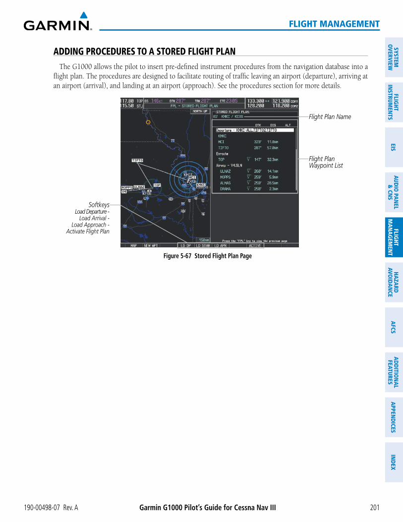
190-00498-07 Rev. A Garmin G1000 Pilot’s Guide for Cessna Nav III 201
FLIGHT MANAGEMENT
SYSTEMO
VERVIEWFLIG
HTIN
STRUMEN
TSEIS
AUDIO
PANEL
& CN
SFLIG
HTM
ANAG
EMEN
THAZARD
AVOIDAN
CEAFCS
ADD
ITION
ALFEATURES
APPEND
ICESIN
DEX
ADDING PROCEDURES TO A STORED FLIGHT PLANThe G1000 allows the pilot to insert pre-defined instrument procedures from the navigation database into a
flight plan. The procedures are designed to facilitate routing of traffic leaving an airport (departure), arriving at an airport (arrival), and landing at an airport (approach). See the procedures section for more details.
Figure 5-67 Stored Flight Plan Page
Flight Plan Name
Flight Plan Waypoint List
SoftkeysLoad Departure -
Load Arrival -Load Approach -
Activate Flight Plan

Garmin G1000 Pilot’s Guide for Cessna Nav III 190-00498-07 Rev. A202
FLIGHT MANAGEMENT
SYST
EMO
VERV
IEW
FLIG
HTIN
STRU
MEN
TSEI
SAU
DIO
PAN
EL&
CN
SFL
IGHT
MAN
AGEM
ENT
HAZA
RDAV
OID
ANCE
AFCS
ADD
ITIO
NAL
FEAT
URES
APPE
ND
ICES
IND
EX
DEPARTURE (DP)A Departure Procedure (DP) is loaded at the departure airport in the flight plan. Only one departure can
be loaded at a time in a flight plan. The route is defined by selection of a departure, the transition waypoints, and a runway.
Figure 5-68 Departure Loading Page - Selecting the Departure
Departure Airport
Selected Departure
Departures Available at KMKC
Departure Waypoint Sequence
Preview of Selected
Departure
Loading a departure procedure into a stored flight plan:
1) Select a stored flight plan from the Flight Plan Catalog Page.
2) Press the EDIT Softkey; or press the MENU Key, select ‘Edit Flight Plan’, and press the ENT Key. The Stored Flight Plan Page is displayed.
3) Press the LD DP Softkey; or press the MENU Key, select “Load Departure”, and press the ENT Key. The Departure Loading Page is displayed.
4) Select a departure. Press the ENT Key.
5) Select a runway served by the selected departure, if required. Press the ENT Key.
6) Select a transition for the selected departure. Press the ENT Key.
7) Press the ENT Key to load the selected departure procedure.
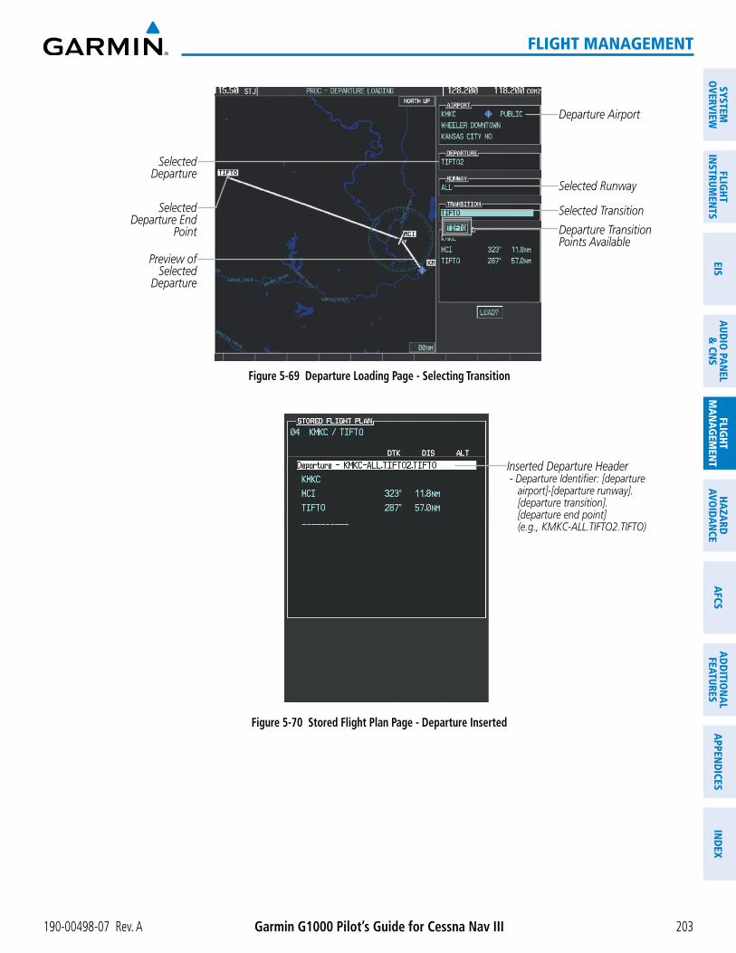
190-00498-07 Rev. A Garmin G1000 Pilot’s Guide for Cessna Nav III 203
FLIGHT MANAGEMENT
SYSTEMO
VERVIEWFLIG
HTIN
STRUMEN
TSEIS
AUDIO
PANEL
& CN
SFLIG
HTM
ANAG
EMEN
THAZARD
AVOIDAN
CEAFCS
ADD
ITION
ALFEATURES
APPEND
ICESIN
DEX
Figure 5-69 Departure Loading Page - Selecting Transition
Departure Airport
Selected Departure
Departure Transition Points Available
Selected Runway
Selected Departure End
Point
Preview ofSelected
Departure
Selected Transition
Figure 5-70 Stored Flight Plan Page - Departure Inserted
Inserted Departure Header - Departure Identifier: [departure airport]-[departure runway]. [departure transition]. [departure end point] (e.g., KMKC-ALL.TIFTO2.TIFTO)
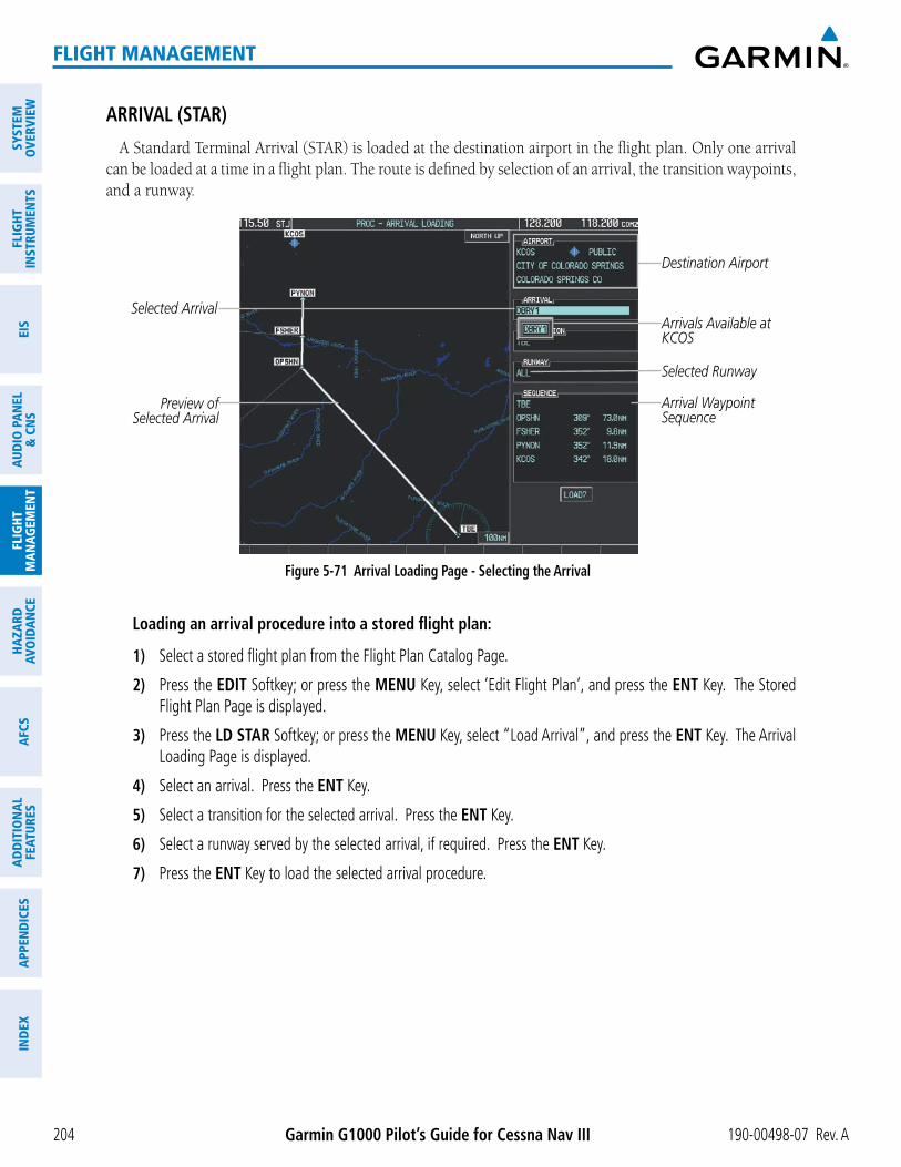
Garmin G1000 Pilot’s Guide for Cessna Nav III 190-00498-07 Rev. A204
FLIGHT MANAGEMENT
SYST
EMO
VERV
IEW
FLIG
HTIN
STRU
MEN
TSEI
SAU
DIO
PAN
EL&
CN
SFL
IGHT
MAN
AGEM
ENT
HAZA
RDAV
OID
ANCE
AFCS
ADD
ITIO
NAL
FEAT
URES
APPE
ND
ICES
IND
EX
ARRIVAL (STAR)A Standard Terminal Arrival (STAR) is loaded at the destination airport in the flight plan. Only one arrival
can be loaded at a time in a flight plan. The route is defined by selection of an arrival, the transition waypoints, and a runway.
Figure 5-71 Arrival Loading Page - Selecting the Arrival
Destination Airport
Selected ArrivalArrivals Available at KCOS
Arrival Waypoint Sequence
Preview of Selected Arrival
Selected Runway
Loading an arrival procedure into a stored flight plan:
1) Select a stored flight plan from the Flight Plan Catalog Page.
2) Press the EDIT Softkey; or press the MENU Key, select ‘Edit Flight Plan’, and press the ENT Key. The Stored Flight Plan Page is displayed.
3) Press the LD STAR Softkey; or press the MENU Key, select “Load Arrival”, and press the ENT Key. The Arrival Loading Page is displayed.
4) Select an arrival. Press the ENT Key.
5) Select a transition for the selected arrival. Press the ENT Key.
6) Select a runway served by the selected arrival, if required. Press the ENT Key.
7) Press the ENT Key to load the selected arrival procedure.

190-00498-07 Rev. A Garmin G1000 Pilot’s Guide for Cessna Nav III 205
FLIGHT MANAGEMENT
SYSTEMO
VERVIEWFLIG
HTIN
STRUMEN
TSEIS
AUDIO
PANEL
& CN
SFLIG
HTM
ANAG
EMEN
THAZARD
AVOIDAN
CEAFCS
ADD
ITION
ALFEATURES
APPEND
ICESIN
DEX
Figure 5-72 Arrival Loading Page - Selecting the Transition
Destination Airport
Selected Arrival
Transitions Available with DBRY1
Arrival Waypoint SequencePreview of
Selected Arrival
Selected Transition
Figure 5-73 Stored Flight Plan Page - Arrival Inserted
Inserted Arrival Header - Arrival Identifier: [arrival airport]-[arrival transition]. [arrival].[arrival runway] (e.g., KCOS-ALS.DBRY1.ALL)

Garmin G1000 Pilot’s Guide for Cessna Nav III 190-00498-07 Rev. A206
FLIGHT MANAGEMENT
SYST
EMO
VERV
IEW
FLIG
HTIN
STRU
MEN
TSEI
SAU
DIO
PAN
EL&
CN
SFL
IGHT
MAN
AGEM
ENT
HAZA
RDAV
OID
ANCE
AFCS
ADD
ITIO
NAL
FEAT
URES
APPE
ND
ICES
IND
EX
APPROACH (APPR)An Approach Procedure (APPR) can be loaded at any airport that has an approach available. Only one
approach can be loaded at a time in a flight plan. The route for a selected approach is defined by designating transition waypoints.
Figure 5-74 Approach Loading Page - Selecting the Approach
Destination Airport
Selected ApproachApproaches Available at KCOS
Approach Waypoint Sequence
Preview of Selected
Approach
Barometric Minimum
Loading an approach procedure into a stored flight plan:
1) Select a stored flight plan from the Flight Plan Catalog Page.
2) Press the EDIT Softkey; or press the MENU Key, select ‘Edit Flight Plan’, and press the ENT Key. The Stored Flight Plan Page is displayed.
3) Press the LD APR Softkey; or press the MENU Key, select “Load Approach”, and press the ENT Key. The Approach Loading Page is displayed.
4) Select an approach. Press the ENT Key.
5) Select a transition for the selected approach. Press the ENT Key.
6) Press the ENT Key to load the selected approach procedure.

190-00498-07 Rev. A Garmin G1000 Pilot’s Guide for Cessna Nav III 207
FLIGHT MANAGEMENT
SYSTEMO
VERVIEWFLIG
HTIN
STRUMEN
TSEIS
AUDIO
PANEL
& CN
SFLIG
HTM
ANAG
EMEN
THAZARD
AVOIDAN
CEAFCS
ADD
ITION
ALFEATURES
APPEND
ICESIN
DEX
Figure 5-75 Approach Loading Page - Selecting the Transition
Destination Airport
Selected Approach
Transitions Available with Selected ApproachApproach Waypoint Sequence
Preview of Selected
Approach
Load Approach?
Selected Transition
Barometric Minimum
Figure 5-76 Stored Flight Plan Page - Approach Inserted
Inserted Approach Header - Approach Identifier: [approach airport].[runway and approach type]
FLIGHT PLAN STORAGEThe G1000 can store up to 99 flight plans, numbered 1 through 99. The active flight plan is erased when
the G1000 is powered off or when another flight plan is activated. Details about each stored flight plan can be viewed on the Flight Plan Catalog Page and on the Stored Flight Plan Page.
Viewing information about a stored flight plan:
1) Press the FPL Key on the MFD to display the Active Flight Plan Page.
2) Turn the small FMS Knob clockwise one click to display the Flight Plan Catalog Page.

Garmin G1000 Pilot’s Guide for Cessna Nav III 190-00498-07 Rev. A208
FLIGHT MANAGEMENT
SYST
EMO
VERV
IEW
FLIG
HTIN
STRU
MEN
TSEI
SAU
DIO
PAN
EL&
CN
SFL
IGHT
MAN
AGEM
ENT
HAZA
RDAV
OID
ANCE
AFCS
ADD
ITIO
NAL
FEAT
URES
APPE
ND
ICES
IND
EX
3) Press the FMS Knob to activate the cursor and turn the FMS Knob to highlight the desired flight plan.
4) The Flight Plan Information is displayed showing departure, destination, total distance, and enroute safe altitude information for the selected Flight Plan.
5) Press the EDIT Softkey to open the Stored Flight Plan Page and view the waypoints in the flight plan.
6) Press the FMS Knob to exit the Stored Flight Plan Page.
Figure 5-77 Stored Flight Plan Information
Preview of Selected Flight Plan
Stored Flight Plan Info - Departure Airport - Destination Airport - Total Flight Plan Distance - Enroute Safe Altitude
Flight Plan Name (Comment)
Selected Flight Plan
Stored FPL Editing Softkeys
Storing an active flight plan from the Active Flight Plan Page or the Active Flight Plan Window:
1) Press the MENU Key.
2) Highlight ‘Store Flight Plan’.
3) Press the ENT Key.
4) With ‘OK’ highlighted, press the ENT Key. The flight plan is stored in the next available position in the flight plan list on the Flight Plan Catalog Page.
ACTIVATE A FLIGHT PLANActivating a stored flight plan erases the active flight plan and replaces it with the flight plan being activated.
Inverting a stored flight plan reverses the waypoint order, erases the active flight plan, and replaces it with the flight plan being activated (the stored flight plan is not changed).
Activating a stored flight plan on the MFD:
1) Press the FPL Key and turn the small FMS Knob to display the Flight Plan Catalog Page.
2) Press the FMS Knob to activate the cursor, and turn the FMS Knob to highlight the desired flight plan.

190-00498-07 Rev. A Garmin G1000 Pilot’s Guide for Cessna Nav III 209
FLIGHT MANAGEMENT
SYSTEMO
VERVIEWFLIG
HTIN
STRUMEN
TSEIS
AUDIO
PANEL
& CN
SFLIG
HTM
ANAG
EMEN
THAZARD
AVOIDAN
CEAFCS
ADD
ITION
ALFEATURES
APPEND
ICESIN
DEX
3) Press the ACTIVE Softkey; or press the ENT Key twice; or press the MENU Key, highlight ‘Activate Flight Plan’, and press the ENT Key. The ‘Activate Stored Flight Plan?’ window is displayed.
4) With ‘OK’ highlighted, press the ENT Key. To cancel the request, press the CLR Key, or highlight ‘CANCEL’ and press the ENT Key.
Inverting and activating a stored flight plan on the MFD:
1) Press the FPL Key and turn the small FMS Knob to display the Flight Plan Catalog Page.
2) Press the FMS Knob to activate the cursor, and turn the FMS Knob to highlight the desired flight plan.
3) Press the INVERT Softkey; or press the MENU Key, highlight ‘Invert & Activate FPL?’, and press the ENT Key. The ‘Invert and activate stored flight plan?’ window is displayed.
4) With ‘OK’ highlighted, press the ENT Key. To cancel the request, press the CLR Key, or highlight ‘CANCEL’ and press the ENT Key.
COPY A FLIGHT PLANThe G1000 allows copying a flight plan into a new flight plan memory slot, allowing editing, etc., without
affecting the original flight plan. This can be used to duplicate an existing stored flight plan for use in creating a modified version of the original stored flight plan.
Copying a stored flight plan on the MFD:
1) Press the FPL Key and turn the small FMS Knob to display the Flight Plan Catalog Page.
2) Press the FMS Knob to activate the cursor, and turn the FMS Knob to highlight the desired flight plan.
3) Press the COPY Softkey; or press the MENU Key, highlight ‘Copy Flight Plan’, and press the ENT Key. The ‘Copy to Flight Plan XX?’ window is displayed.
4) With ‘OK’ highlighted, press the ENT Key to copy the flight plan. To cancel the request, press the CLR Key, or highlight ‘CANCEL’ and press the ENT Key.
DELETE A STORED FLIGHT PLANIndividual or all stored flight plans can be deleted from the G1000 memory.
Deleting a stored flight plan:
1) Press the FPL Key and turn the small FMS Knob to display the Flight Plan Catalog Page.
2) Press the FMS Knob to activate the cursor, and turn the FMS Knob to highlight the desired flight plan.
3) Press the DELETE Softkey; press the CLR Key; or press the MENU Key, highlight ‘Delete Flight Plan’, and press the ENT Key. The ‘Delete Flight Plan XX?’ window is displayed.
4) With ‘OK’ highlighted, press the ENT Key to delete the flight plan. To cancel the request, press the CLR Key, or highlight ‘CANCEL’ and press the ENT Key.
NOTE: The option to delete all stored flight plans is not available while the aircraft is in flight.

Garmin G1000 Pilot’s Guide for Cessna Nav III 190-00498-07 Rev. A210
FLIGHT MANAGEMENT
SYST
EMO
VERV
IEW
FLIG
HTIN
STRU
MEN
TSEI
SAU
DIO
PAN
EL&
CN
SFL
IGHT
MAN
AGEM
ENT
HAZA
RDAV
OID
ANCE
AFCS
ADD
ITIO
NAL
FEAT
URES
APPE
ND
ICES
IND
EX
Deleting all stored flight plans:
1) Press the FPL Key and turn the small FMS Knob to display the Flight Plan Catalog Page.
2) Press the MENU Key.
3) Highlight ‘Delete All’ and press the ENT Key. A ‘Delete all flight plans?’ confirmation window is displayed.
4) With ‘OK’ highlighted, press the ENT Key to delete all flight plans. To cancel the request, press the CLR Key, or highlight ‘CANCEL’ and press the ENT Key.
FLIGHT PLAN EDITINGThe active flight plan or any stored flight plan can be edited. The edits made to the active flight plan affect
navigation as soon as they are entered.
DELETING THE ACTIVE FLIGHT PLANThe G1000 allows deleting an active flight plan. Deleting the active flight plan suspends navigation by the
G1000.
Deleting the active flight plan:
1) Press the FPL Key to display the Active Flight Plan Page (MFD) or the Active Flight Plan Window (PFD).
2) Press the MENU Key, highlight ‘Delete Flight Plan’, and press the ENT Key. The ‘Delete all waypoints in flight plan?’ window is displayed.
3) With ‘OK’ highlighted, press the ENT Key to delete the active flight plan. To cancel the request, press the CLR Key, or highlight ‘CANCEL’ and press the ENT Key.
DELETING FLIGHT PLAN ITEMSIndividual waypoints, entire airways, and entire procedures can be deleted from a flight plan. Some waypoints
in the final approach segment (such as the FAF or MAP) can not be deleted individually. Attempting to delete
Deleting an individual waypoint from the active flight plan:
1) Press the FPL Key to display the Active Flight Plan Page (MFD) or the Active Flight Plan Window (PFD).
2) Press the FMS Knob to activate the cursor (not required on the PFD) and turn the large FMS Knob to highlight the waypoint to be deleted.
3) Press the CLR Key. The ‘Remove XXXXX?’ window is displayed.
4) With ‘OK’ highlighted, press the ENT Key. To cancel the request, press the CLR Key, or highlight ‘CANCEL’ and press the ENT Key.
5) Press the FMS Knob to remove the flashing cursor.

190-00498-07 Rev. A Garmin G1000 Pilot’s Guide for Cessna Nav III 211
FLIGHT MANAGEMENT
SYSTEMO
VERVIEWFLIG
HTIN
STRUMEN
TSEIS
AUDIO
PANEL
& CN
SFLIG
HTM
ANAG
EMEN
THAZARD
AVOIDAN
CEAFCS
ADD
ITION
ALFEATURES
APPEND
ICESIN
DEX
Deleting an entire airway from the active flight plan:
1) Press the FPL Key to display the Active Flight Plan Page (MFD) or the Active Flight Plan Window (PFD).
2) Press the FMS Knob to activate the cursor (not required on the PFD) and turn the large FMS Knob to highlight the white header of the airway to be deleted.
3) Press the CLR Key. The ‘Remove <airway name>?’ window is displayed.
4) With ‘OK’ highlighted, press the ENT Key. To cancel the request, press the CLR Key, or highlight ‘CANCEL’ and press the ENT Key.
5) Press the FMS Knob to remove the flashing cursor.
Deleting an entire procedure from the active flight plan:
1) Press the FPL Key to display the Active Flight Plan Page (MFD) or the Active Flight Plan Window (PFD).
2) Press the FMS Knob to activate the cursor (not required on the PFD) and turn the large FMS Knob to highlight the white header of the procedure to be deleted.
3) Press the CLR Key. The ‘Remove <procedure name> from flight plan?’ window is displayed.
4) With ‘OK’ highlighted, press the ENT Key. To cancel the request, press the CLR Key, or highlight ‘CANCEL’ and press the ENT Key.
5) Press the FMS Knob to remove the flashing cursor.
Or:
1) Press the FPL Key to display the Active Flight Plan Page (MFD) or the Active Flight Plan Window (PFD).
2) Press the MENU Key to display the Page Menu and turn the FMS Knob to highlight ‘Remove <procedure>’.
3) Press the ENT Key. The ‘Remove <procedure name> from flight plan?’ window is displayed.
4) With ‘OK’ highlighted, press the ENT Key. To cancel the request, press the CLR Key, or highlight ‘CANCEL’ and press the ENT Key.
Deleting an individual waypoint from a stored flight plan:
1) Press the FPL Key to display the Active Flight Plan Page.
2) Turn the small FMS Knob clockwise one click to display the Flight Plan Catalog Page.
3) Press the FMS Knob to activate the cursor and turn the FMS Knob to highlight the flight plan to be edited.
4) Press the EDIT Softkey; or press the MENU Key, select ‘Edit Flight Plan’ and press the ENT Key. The Stored Flight Plan Page is displayed.
5) Turn the large FMS Knob to highlight the waypoint to be deleted.
6) Press the CLR Key. The ‘Remove XXXXX?’ window is displayed.
7) With ‘OK’ highlighted, press the ENT Key. To cancel the request, press the CLR Key, or highlight ‘CANCEL’ and press the ENT Key.
8) Press the FMS Knob to remove the flashing cursor.

Garmin G1000 Pilot’s Guide for Cessna Nav III 190-00498-07 Rev. A212
FLIGHT MANAGEMENT
SYST
EMO
VERV
IEW
FLIG
HTIN
STRU
MEN
TSEI
SAU
DIO
PAN
EL&
CN
SFL
IGHT
MAN
AGEM
ENT
HAZA
RDAV
OID
ANCE
AFCS
ADD
ITIO
NAL
FEAT
URES
APPE
ND
ICES
IND
EX
Deleting an entire airway from a stored flight plan:
1) Press the FPL Key to display the Active Flight Plan Page.
2) Turn the small FMS Knob clockwise one click to display the Flight Plan Catalog Page.
3) Press the FMS Knob to activate the cursor and turn the FMS Knob to highlight the flight plan to be edited.
4) Press the EDIT Softkey; or press the MENU Key, select ‘Edit Flight Plan’ and press the ENT Key. The Stored Flight Plan Page is displayed.
5) Turn the large FMS Knob to highlight the white header of the airway to be deleted.
6) Press the CLR Key. The ‘Remove <airway name>?’ window is displayed.
7) With ‘OK’ highlighted, press the ENT Key. To cancel the request, press the CLR Key, or highlight ‘CANCEL’ and press the ENT Key.
8) Press the FMS Knob to remove the flashing cursor.
Deleting an entire procedure from a stored flight plan:
1) Press the FPL Key to display the Active Flight Plan Page.
2) Turn the small FMS Knob clockwise one click to display the Flight Plan Catalog Page.
3) Press the FMS Knob to activate the cursor and turn the FMS Knob to highlight the flight plan to be edited.
4) Press the EDIT Softkey; or press the MENU Key, select ‘Edit Flight Plan’ and press the ENT Key. The Stored Flight Plan Page is displayed.
5) Turn the large FMS Knob to highlight the white header of the procedure to be deleted.
6) Press the CLR Key. The ‘Remove <procedure name> from flight plan?’ window is displayed.
7) With ‘OK’ highlighted, press the ENT Key. To cancel the request, press the CLR Key, or highlight ‘CANCEL’ and press the ENT Key.
8) Press the FMS Knob to remove the flashing cursor.
Or:
1) Press the FPL Key to display the Active Flight Plan Page.
2) Turn the small FMS Knob clockwise one click to display the Flight Plan Catalog Page.
3) Press the FMS Knob to activate the cursor and turn the FMS Knob to highlight the flight plan to be edited.
4) Press the EDIT Softkey; or press the MENU Key, select ‘Edit Flight Plan’ and press the ENT Key. The Stored Flight Plan Page is displayed.
5) Press the MENU Key to display the Page Menu and turn the FMS Knob to highlight ‘Remove <procedure>’.
6) Press the ENT Key. The ‘Remove <procedure name> from flight plan?’ window is displayed.
7) With ‘OK’ highlighted, press the ENT Key. To cancel the request, press the CLR Key, or highlight ‘CANCEL’ and press the ENT Key.
8) Press the FMS Knob to remove the flashing cursor.
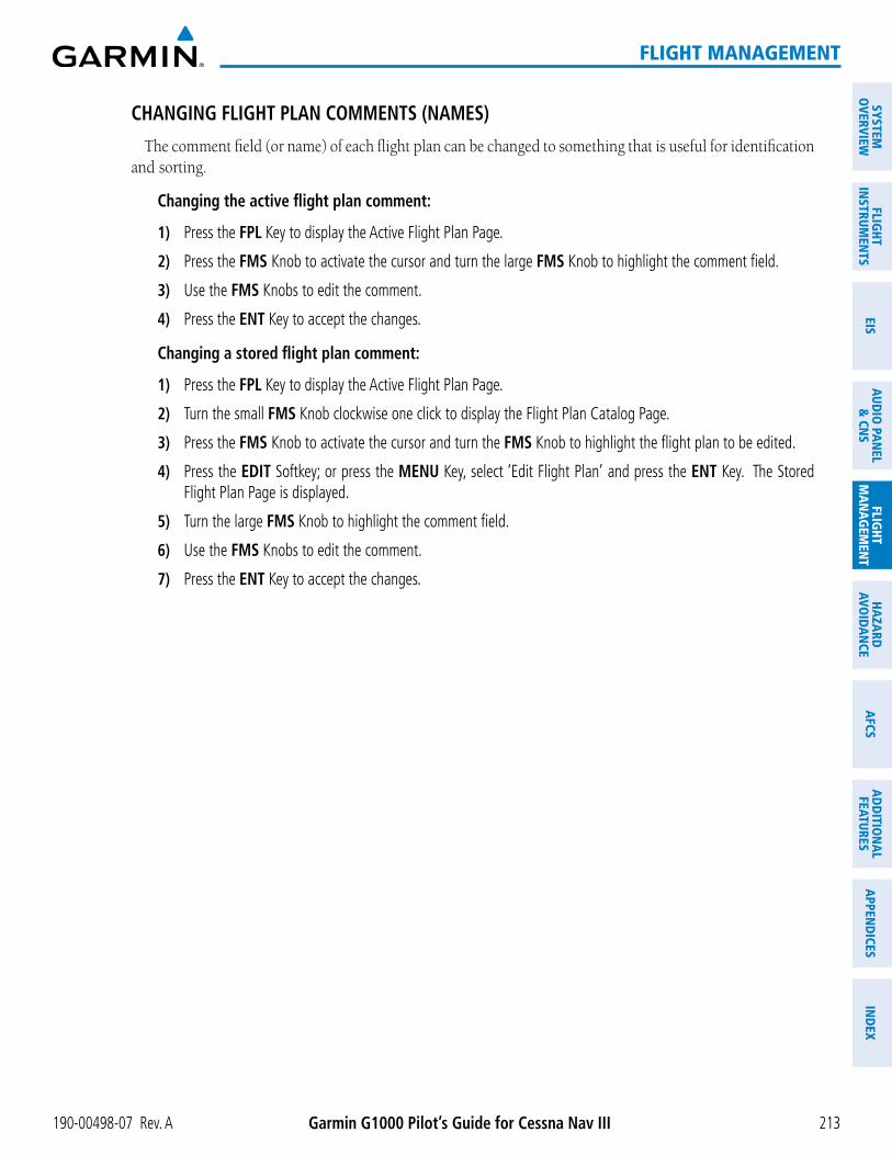
190-00498-07 Rev. A Garmin G1000 Pilot’s Guide for Cessna Nav III 213
FLIGHT MANAGEMENT
SYSTEMO
VERVIEWFLIG
HTIN
STRUMEN
TSEIS
AUDIO
PANEL
& CN
SFLIG
HTM
ANAG
EMEN
THAZARD
AVOIDAN
CEAFCS
ADD
ITION
ALFEATURES
APPEND
ICESIN
DEX
CHANGING FLIGHT PLAN COMMENTS (NAMES)The comment field (or name) of each flight plan can be changed to something that is useful for identification
and sorting.
Changing the active flight plan comment:
1) Press the FPL Key to display the Active Flight Plan Page.
2) Press the FMS Knob to activate the cursor and turn the large FMS Knob to highlight the comment field.
3) Use the FMS Knobs to edit the comment.
4) Press the ENT Key to accept the changes.
Changing a stored flight plan comment:
1) Press the FPL Key to display the Active Flight Plan Page.
2) Turn the small FMS Knob clockwise one click to display the Flight Plan Catalog Page.
3) Press the FMS Knob to activate the cursor and turn the FMS Knob to highlight the flight plan to be edited.
4) Press the EDIT Softkey; or press the MENU Key, select ‘Edit Flight Plan’ and press the ENT Key. The Stored Flight Plan Page is displayed.
5) Turn the large FMS Knob to highlight the comment field.
6) Use the FMS Knobs to edit the comment.
7) Press the ENT Key to accept the changes.

Garmin G1000 Pilot’s Guide for Cessna Nav III 190-00498-07 Rev. A214
FLIGHT MANAGEMENT
SYST
EMO
VERV
IEW
FLIG
HTIN
STRU
MEN
TSEI
SAU
DIO
PAN
EL&
CN
SFL
IGHT
MAN
AGEM
ENT
HAZA
RDAV
OID
ANCE
AFCS
ADD
ITIO
NAL
FEAT
URES
APPE
ND
ICES
IND
EX
ALONG TRACK OFFSETSA waypoint having an “along track offset” distance from an existing waypoint can be entered into a flight plan.
Along track offset waypoints lie along the path of the existing flight plan, and can be used to make the system reach a specified altitude before or after reaching the specified flight plan waypoint. Offset distances can be entered from 1 to 99 nm in increments of 1 nm. Entering a negative offset distance results in an along track offset waypoint inserted before the selected waypoint, whereas entering a positive offset distance results in an along track offset waypoint inserted after the selected waypoint. Multiple offset waypoints are allowed.
A waypoint must be adjacent to its parent waypoint in the flight plan, so the system limits the along-track distance to less than the length of the leg before or after the selected waypoint. If the selected waypoint is the active waypoint, the distance is limited to less than the distance to go to the active waypoint. Assigning an along track offset to a leg with indeterminate length is not permitted. An along track offset is not allowed at or after the final approach fix of an approach.
An along track offset distance cannot be modified once entered. If the along track offset distance must be changed, the existing along track offset waypoint must be deleted and a new one created with the new offset distance.
Figure 5-78 Along Track Offset
Along Track Offset Waypoint
and Distance
Along Track Offset Waypoint and Distance from Flight Plan Waypoint
Entering an along track offset distance:
1) Press the FPL Key to display the Active Flight Plan Page (MFD) or the Active Flight Plan Window (PFD).
2) Press the FMS Knob to activate the cursor (not required on the PFD) and turn the large FMS Knob to highlight the waypoint for the along track offset.
3) Press the ATK OFST Softkey (MFD only); or press the MENU Key, highlight ‘Create ATK Offset Waypoint’, and press the ENT Key.
4) Enter a positive or negative offset distance in the range of +/- 1 to 99 nm (limited by leg distances).
5) Press the ENT Key to create the offset waypoint.
6) Press the FMS Knob to remove the flashing cursor.

190-00498-07 Rev. A Garmin G1000 Pilot’s Guide for Cessna Nav III 215
FLIGHT MANAGEMENT
SYSTEMO
VERVIEWFLIG
HTIN
STRUMEN
TSEIS
AUDIO
PANEL
& CN
SFLIG
HTM
ANAG
EMEN
THAZARD
AVOIDAN
CEAFCS
ADD
ITION
ALFEATURES
APPEND
ICESIN
DEX
PARALLEL TRACKThe Parallel Track (PTK) feature allows creation of a parallel course offset of 1 to 50 nm left or right of the
current flight plan. When Parallel Track is activated, the course line drawn on the map pages shows the parallel course, and waypoint names have a lower case “p” placed after the identifier.
Using direct-to, loading an approach, a holding pattern, or editing and activating the flight plan automatically cancels Parallel Track. Parallel Track is also cancelled if a course change occurs greater than 120° or the parallel tracks overlap as a result of the course change.
NOTE: Vertical navigation is unavailable while the Parallel Track feature is active.
Figure 5-79 Active Flight Plan Window - Selecting Parallel Track
Selecting Parallel Track
Active Flight Plan prior to Parallel Track
Activating parallel track:
1) Press the FPL Key to display the Active Flight Plan Page (MFD) or the Active Flight Plan Window (PFD)
2) Press the MENU Key, highlight ‘Parallel Track’, and press the ENT Key. The Parallel Track Window is displayed with the direction field highlighted.
3) Turn the small FMS Knob to select ‘Left’ or ‘Right’ and press the ENT Key. The ‘DISTANCE’ field is highlighted.
4) Turn the small FMS Knob to enter a distance from 1-99 nm and press the ENT Key. ‘ACTIVATE PARALLEL TRACK’ is highlighted.
5) Press the ENT Key to activate parallel track. Press the FMS Knob or the CLR Key to cancel the parallel track activation.

Garmin G1000 Pilot’s Guide for Cessna Nav III 190-00498-07 Rev. A216
FLIGHT MANAGEMENT
SYST
EMO
VERV
IEW
FLIG
HTIN
STRU
MEN
TSEI
SAU
DIO
PAN
EL&
CN
SFL
IGHT
MAN
AGEM
ENT
HAZA
RDAV
OID
ANCE
AFCS
ADD
ITIO
NAL
FEAT
URES
APPE
ND
ICES
IND
EX
Figure 5-80 Parallel Track Window
Offset DirectionOffset Distance
Activation Prompt
Figure 5-81 Parallel Track Active
Parallel Track Waypoints - TIFTO-p - TOP-p - ... - LAA-pActivating Parallel Track affects the active flight plan from the current position on (will not affect an approach)
Parallel Track
Original Track
If the parallel track proposed by the offset direction and distance is not allowed by the system, the activation prompt is displayed, but disabled. Parallel Track cannot be activated if a course is set using direct-to or if the active leg is the first leg of the departure procedure. Attempting to activate parallel track with these conditions

190-00498-07 Rev. A Garmin G1000 Pilot’s Guide for Cessna Nav III 217
FLIGHT MANAGEMENT
SYSTEMO
VERVIEWFLIG
HTIN
STRUMEN
TSEIS
AUDIO
PANEL
& CN
SFLIG
HTM
ANAG
EMEN
THAZARD
AVOIDAN
CEAFCS
ADD
ITION
ALFEATURES
APPEND
ICESIN
DEX
Approach Leg Active’. If the offset direction and distance results in an unreasonable route geometry the status indicates that the system is unable to activate the parallel track because of invalid geometry.
Figure 5-82 Parallel Track Unavailable
Subdued Prompt(Unavailable)
Unavailable StatusInvalid ApproachGeometry Active
If the active leg is not a track between two fixes (TF) or a course to a fix (DF) leg, the status indicates that the system is unable to activate the parallel track because parallel track is not available for the active leg type.
Figure 5-83 Cancelling Parallel Track
Cancel Prompt
Active Status
Offset Direction&Offset DistanceSubdued (Unavailable)
Cancelling parallel track:
1) Press the FPL Key to display the Active Flight Plan Page (MFD) or the Active Flight Plan Window (PFD)
2) Press the MENU Key, highlight ‘Parallel Track’, and press the ENT Key. The Parallel Track Window is displayed with ‘CANCEL PARALLEL TRACK?’ highlighted.
3) Press the ENT Key.

Garmin G1000 Pilot’s Guide for Cessna Nav III 190-00498-07 Rev. A218
FLIGHT MANAGEMENT
SYST
EMO
VERV
IEW
FLIG
HTIN
STRU
MEN
TSEI
SAU
DIO
PAN
EL&
CN
SFL
IGHT
MAN
AGEM
ENT
HAZA
RDAV
OID
ANCE
AFCS
ADD
ITIO
NAL
FEAT
URES
APPE
ND
ICES
IND
EX
ACTIVATING A FLIGHT PLAN LEGThe G1000 allows selection of a highlighted leg as the “active leg” (the flight plan leg which is currently
used for navigation guidance).
Activating a flight plan leg:
1) Press the FPL Key to display the Active Flight Plan Page (MFD) or the Active Flight Plan Window (PFD)
2) Press the FMS Knob to activate the cursor (not required on the PFD) and turn the large FMS Knob to highlight the destination waypoint for the desired leg.
3) Press the ACT LEG Softkey (MFD only); or press the MENU Key, highlight ‘Activate Leg’, and press the ENT Key. A confirmation window is displayed with ‘ACTIVATE’ highlighted.
4) Press the ENT Key to activate the flight plan leg. To cancel, press the CLR Key, or highlight ‘CANCEL’ and press the ENT Key.
5) Press the FMS Knob to remove the flashing cursor.
Figure 5-84 Active Flight Plan Page - Selecting the Leg Destination Waypoint
Current Active Leg
Activate Leg Softkey
Selected Destination Waypoint

190-00498-07 Rev. A Garmin G1000 Pilot’s Guide for Cessna Nav III 219
FLIGHT MANAGEMENT
SYSTEMO
VERVIEWFLIG
HTIN
STRUMEN
TSEIS
AUDIO
PANEL
& CN
SFLIG
HTM
ANAG
EMEN
THAZARD
AVOIDAN
CEAFCS
ADD
ITION
ALFEATURES
APPEND
ICESIN
DEX
Figure 5-85 Active Flight Plan Page - New Active Leg
New ActiveFlight Plan Leg
Confirmation Window
INVERTING A FLIGHT PLANAny flight plan may be inverted (reversed) for navigation back to the original departure point.
Inverting the active flight plan:
1) Press the FPL Key to display the Active Flight Plan Page (MFD) or the Active Flight Plan Window (PFD)
2) Press the MENU Key, highlight ‘Invert Flight Plan’, and press the ENT Key. An ‘Invert Active Flight Plan?’ confirmation window is displayed.
3) Select ‘OK’.
4) Press the ENT Key to invert and activate the active flight plan. To cancel, press the CLR Key, or highlight ‘CANCEL’ and press the ENT Key.
Inverting and activating a stored flight plan:
1) Press the FPL Key and turn the small FMS Knob to display the Flight Plan Catalog Page.
2) Press the FMS Knob to activate the cursor, and turn the FMS Knob to highlight the desired flight plan.
3) Press the INVERT Softkey; or press the MENU Key, highlight ‘Invert & Activate FPL?’, and press the ENT Key. The ‘Invert and activate stored flight plan?’ window is displayed.
4) With ‘OK’ highlighted, press the ENT Key. To cancel the request, press the CLR Key, or highlight ‘CANCEL’ and press the ENT Key.

Garmin G1000 Pilot’s Guide for Cessna Nav III 190-00498-07 Rev. A220
FLIGHT MANAGEMENT
SYST
EMO
VERV
IEW
FLIG
HTIN
STRU
MEN
TSEI
SAU
DIO
PAN
EL&
CN
SFL
IGHT
MAN
AGEM
ENT
HAZA
RDAV
OID
ANCE
AFCS
ADD
ITIO
NAL
FEAT
URES
APPE
ND
ICES
IND
EX
FLIGHT PLAN VIEWSInformation about flight plans can be viewed in more than one way. The active flight plan can be configured
to show cumulative distance over the length of the flight plan or the distance for each leg of the flight plan; and the active flight plan can be viewed in a narrow or wide view. In the wide view, additional information is displayed: Fuel Remaining (FUEL REM), Estimated Time Enroute (ETE), Estimated Time of Arrival (ETA), and Bearing to the waypoint (BRG).
Switching between leg-to-leg waypoint distance and cumulative waypoint distance:
1) Press the FPL Key on the MFD to display the Active Flight Plan Page.
2) Press the VIEW Softkey to display the CUM and LEG-LEG Softkeys.
3) Press the CUM Softkey to view cumulative waypoint distance, or press the LEG-LEG Softkey to view leg-to-leg waypoint distance.
4) Press the BACK Softkey to return to the top level active flight plan softkeys.
Figure 5-86 Active Flight Plan - Leg to Leg vs. Cumulative Distance
WIDE Softkey, NARROW Softkey, LEG-LEG Softkey, CUM Softkey
Active Flight Plan Leg to Leg Distance Active Flight Plan Cumulative Distance
Switching between wide and narrow view:
1) Press the FPL Key on the MFD to display the Active Flight Plan Page.
2) Press the VIEW Softkey to display the WIDE and NARROW Softkeys.
3) Press the WIDE Softkey to display the wide view, or press the NARROW Softkey to display the narrow view.
4) Press the BACK Softkey to return to the top level active flight plan softkeys.

190-00498-07 Rev. A Garmin G1000 Pilot’s Guide for Cessna Nav III 221
FLIGHT MANAGEMENT
SYSTEMO
VERVIEWFLIG
HTIN
STRUMEN
TSEIS
AUDIO
PANEL
& CN
SFLIG
HTM
ANAG
EMEN
THAZARD
AVOIDAN
CEAFCS
ADD
ITION
ALFEATURES
APPEND
ICESIN
DEX
Figure 5-87 Active Flight Plan - Wide vs. Narrow View
WIDE Softkey, NARROW Softkey, LEG-LEG Softkey, CUM Softkey
Active Flight Plan Leg to Leg Distance Active Flight Plan Cumulative Distance
COLLAPSING AIRWAYSThe G1000 allows airways on the active flight plan to be collapsed or expanded from the Active Flight Plan
Page/Window. When airways have been collapsed, it is indicated on the airway heading.
When airways are collapsed, leg-to-leg computed values such as DIS or ETE shown for the exit waypoint reflect the total of all the legs on the airway that have been hidden in the collapsed display. The DTK value is inhibited because it is not usable in this context.
The Active Flight Plan Page always keeps the following three waypoints visible: “From” waypoint, “To” waypoint, and “Next” waypoint. To prevent one or more of these waypoints from being hidden in a collapsed airway segment, the airway segment that contains either the “To” or the “Next” waypoint is automatically expanded. When an airway is loaded, airways are automatically expanded to facilitate flight plan review.

Garmin G1000 Pilot’s Guide for Cessna Nav III 190-00498-07 Rev. A222
FLIGHT MANAGEMENT
SYST
EMO
VERV
IEW
FLIG
HTIN
STRU
MEN
TSEI
SAU
DIO
PAN
EL&
CN
SFL
IGHT
MAN
AGEM
ENT
HAZA
RDAV
OID
ANCE
AFCS
ADD
ITIO
NAL
FEAT
URES
APPE
ND
ICES
IND
EX
Figure 5-88 Expanded/Collapsed Airways
Q3.FEPOT AirwayCollapsed View
Expanded View
Collapsing/expanding the airways in the active flight plan:
1) Press the FPL Key to display the Active Flight Plan Page (MFD) or the Active Flight Plan Window (PFD).
2) Press the MENU Key, highlight ‘Collapse Airways’ or ‘Expand Airways’, and press the ENT Key. The airways are collapsed/expanded.
CLOSEST POINT OF FPL
waypoint, and creates a new user waypoint along the flight plan at the location closest to a chosen reference waypoint.
Determining the closest point along the active flight plan to a selected waypoint:
1) Press the FPL Key to display the Active Flight Plan Page (MFD) or the Active Flight Plan Window (PFD).
2) Press the MENU Key, highlight ‘Closest Point Of FPL’’, and press the ENT Key. A window appears with the reference waypoint field highlighted.
3) Enter the identifier of the reference waypoint and press the ENT Key. The G1000 displays the bearing (BRG) and distance (DIS) to the closest point along the flight plan to the selected reference waypoint and creates a user waypoint at this location. The name for the new user waypoint is derived from the identifier of the reference waypoint.

190-00498-07 Rev. A Garmin G1000 Pilot’s Guide for Cessna Nav III 223
FLIGHT MANAGEMENT
SYSTEMO
VERVIEWFLIG
HTIN
STRUMEN
TSEIS
AUDIO
PANEL
& CN
SFLIG
HTM
ANAG
EMEN
THAZARD
AVOIDAN
CEAFCS
ADD
ITION
ALFEATURES
APPEND
ICESIN
DEX
5.7 VERTICAL NAVIGATION
NOTE: The G1000 supports vertical navigation for all lateral leg types except for CA, CI, FA, FM, HA, HM, PI, VA, VD, VI, VR, and VM. Vertical constraints are not retained in stored flight plans.
The G1000 system Vertical Navigation (VNV) feature provides vertical profile guidance during the enroute and teminal phases of flight. Guidance based on specified altitudes at waypoints in the active flight plan or to a direct-to waypoint is provided. It includes vertical path guidance to a descending path, which is provided as a linear deviation from the desired path. The desired path is defined by a line joining two waypoints with specified altitudes or as a vertical angle from a specified waypoint/altitude. The vertical waypoints are integrated into the active flight plan. Both manual and autopilot-coupled guidance are supported.
Figure 5-89 Enabling/Disabling Vertical Navigation
CNCL VNV Softkey
Current Vertical Navigation ProfileDisabled (fields dashed)
ENBL VNV Softkey
Current Vertical Navigation ProfileEnabled (valid data)
Enabling VNV guidance:
1) Press the FPL Key to display the Active Flight Plan Page on the MFD.
2) Press the ENBL VNV Softkey; or press the MENU Key, highlight ‘Enable VNV’, and press the ENT Key. Vertical navigation is enabled, and vertical guidance begins with the waypoint shown in the CURRENT VNV PROFILE box (defaults first waypoint in the active flight plan with an altitude enabled for vertical navigation (e.g., HABUK)).
Disabling VNV guidance:
1) Press the FPL Key to display the Active Flight Plan Page on the MFD.
2) Press the CNCL VNV Softkey; or press the MENU Key, highlight ‘Cancel VNV’, and press the ENT Key. Vertical navigation is disabled.

Garmin G1000 Pilot’s Guide for Cessna Nav III 190-00498-07 Rev. A224
FLIGHT MANAGEMENT
SYST
EMO
VERV
IEW
FLIG
HTIN
STRU
MEN
TSEI
SAU
DIO
PAN
EL&
CN
SFL
IGHT
MAN
AGEM
ENT
HAZA
RDAV
OID
ANCE
AFCS
ADD
ITIO
NAL
FEAT
URES
APPE
ND
ICES
IND
EX
to top of descent/bottom of descent (TIME TO TOD/BOD) going invalid. The Vertical Deviation Indicator (VDI)
TOD items displayed in the CURRENT VNV PROFILE box are dashed. VNV remains disabled until manually enabled. Vertical guidance in reversionary mode can only be enabled for a direct-to waypoint.
The G1000 allows a vertical navigation direct-to to any waypoint in the active flight plan with an altitude constraint “designated” for vertical guidance. Pressing the VNV Direct-to Softkey on the Active Flight Plan Page allows the flight plan to be flown, while vertical guidance based on the altitude constraint at the VNV direct-to waypoint is provided. The altitude change begins immediately and is spread along the flight plan from current position to the vertical direct-to waypoint, not just along the leg for the direct-to waypoint. A direct-to with altitude constraint activated by pressing the Direct-to Key also provides vertical guidance, but would bypass flight plan waypoints between the current position in the flight plan and the direct-to waypoint. A top of descent (TOD) point is computed based on the default flight path angle; descent begins once the TOD is reached.
Figure 5-90 Vertical Navigation Direct-To
Current Vertical Navigation ProfilePrior to VNV Direct-to
VNV Direct-To Softkey VNV PROF Softkey
Current Vertical Navigation ProfileAfter VNV Direct-to
Activating a vertical navigation direct-to:
1) Press the FPL Key to display the Active Flight Plan Page on the MFD.
2) Press the FMS Knob to activate the cursor and turn the FMS Knob to highlight the desired waypoint.
NOTE: The selected waypoint must have a designated altitude constraint (light blue number) to be used. If not, the first waypoint in the flight plan with a designated altitude constraint is selected.
3) Select the VNV Direct-To Softkey; or press the MENU Key, highlight ‘VNV Direct-To’, and press the ENT Key. An ‘Activate vertical Direct-to to: NNNNNFT at XXXXXX?’ confirmation window is displayed.

190-00498-07 Rev. A Garmin G1000 Pilot’s Guide for Cessna Nav III 225
FLIGHT MANAGEMENT
SYSTEMO
VERVIEWFLIG
HTIN
STRUMEN
TSEIS
AUDIO
PANEL
& CN
SFLIG
HTM
ANAG
EMEN
THAZARD
AVOIDAN
CEAFCS
ADD
ITION
ALFEATURES
APPEND
ICESIN
DEX
4) Press the ENT Key. Vertical guidance begins to the altitude constraint for the selected waypoint.
5) Press the FMS Knob to remove the flashing cursor.
The vertical navigation profile can be modified by directly entering a vertical speed target (VS TGT) and/or flight path angle (FPA) in the CURRENT VNV PROFILE box.
Modifying the VS TGT and FPA:
1) Press the FPL Key to display the Active Flight Plan Page on the MFD.
2) Press the VNV PROF Softkey; or press the MENU Key, highlight ‘Select VNV Profile Window’, and press the ENT Key. The cursor is now located in the CURRENT VNV PROFILE box without having to scroll all the way through past the end of the active flight plan.
3) Turn the FMS Knobs as needed to edit the values.
4) Press the FMS Knob to remove the flashing cursor.
ALTITUDE CONSTRAINTSThe G1000 system can use altitude constraints associated with lateral waypoints to give guidance for vertical
navigation. These altitudes are, depending on the specific instance, manually entered or retrieved from the published altitudes in the navigation database. The navigation database only contains altitudes for procedures that call for “Cross at” altitudes. If the procedure states “Expect to cross at,” then the altitude is not in the database. In this case the altitude may be entered manually.
Large Light Blue Text
Small White Text with Altitude Restriction Bar
Large White Text
Small Light Blue Subdued Text
Small Light Blue Text
Figure 5-91 Waypoint Altitude Constraints
Cross AT or ABOVE 5,000 ft
Cross AT or BELOW 3,000 ft
Cross AT 2,300 ft
Altitude ConstraintExamples
Displayed Text Examples

Garmin G1000 Pilot’s Guide for Cessna Nav III 190-00498-07 Rev. A226
FLIGHT MANAGEMENT
SYST
EMO
VERV
IEW
FLIG
HTIN
STRU
MEN
TSEI
SAU
DIO
PAN
EL&
CN
SFL
IGHT
MAN
AGEM
ENT
HAZA
RDAV
OID
ANCE
AFCS
ADD
ITIO
NAL
FEAT
URES
APPE
ND
ICES
IND
EX
White Text Light Blue Text Light Blue Subdued Text
Large Text
Altitude calculated by the system estimating the altitude of the aircraft as it passes over the navigation point. This altitude is provided as a reference and is not designated to be used in determining vertical speed and deviation guidance.
Altitude has been entered manually. Altitude is designated for use in giving vertical speed and deviation guidance. Altitude does not match the published altitude in navigation database or no published altitude exists.
The system cannot use this altitude in determining vertical speed and deviation guidance because of an invalid constraint condition.
Small Text
Altitude is not designated to be used in determining vertical speed and deviation guidance. Altitude has been retrieved from the navigation database and is provided as a reference.
Altitude is designated for use in giving vertical speed and deviation guidance. Altitude has been retrieved from the navigation database or has been entered manually and matches a published altitude in the navigation database.
The system cannot use this altitude in determining vertical speed and deviation guidance because of an invalid constraint condition.
Table 5-8 Altitude Constraint Size and Color Coding
Altitudes associated with approach procedures are “auto-designated”. This means the system automatically uses the altitudes loaded with the approach for giving vertical speed and deviation guidance. Note that these altitudes are displayed as blue text up to, but not including, the FAF. The FAF is always a “reference only” altitude and cannot be designated, unless the selected approach does not provide vertical guidance. In this case, the FAF altitude can be designated.
Altitudes that have been designated for use in vertical guidance can be “un-designated” using the CLR Key. The altitude is now displayed only as a reference. It is not used to give vertical guidance. Other displayed altitudes may change due to re-calculations or be rendered invalid as a result of manually changing an altitude to a non-designated altitude.
Designating a waypoint altitude to be used for vertical guidance:
1) Press the FPL Key to display the Active Flight Plan Page on the MFD.
2) Press the FMS Knob, and turn to highlight the desired waypoint altitude.
3) Turn the small FMS Knob to enter editing mode.
4) Press the ENT Key. The altitude is now shown in blue, indicating it is usable for vertical guidance.
Designating a procedure waypoint altitude to be used for vertical guidance:
1) Press the FPL Key to display the Active Flight Plan Page on the MFD.
2) Press the FMS Knob, and turn to highlight the desired waypoint altitude.
3) Press the ENT Key. The altitude is now shown in blue, indicating it is usable for vertical guidance.
Altitude constraints are displayed and entered in feet mean sea level (MSL) values to the nearest hundred. An altitude constraint in feet above ground level (AGL) format is supported for airports. When a database altitude restriction is displayed, the G1000 allows entry of a different altitude when creating a waypoint, effectively overriding the database restriction (only before the FAF). When a database altitude restriction of type “AT or ABOVE” or “AT or BELOW” is activated, the system uses the “AT” portion of the restriction to define the vertical profile.
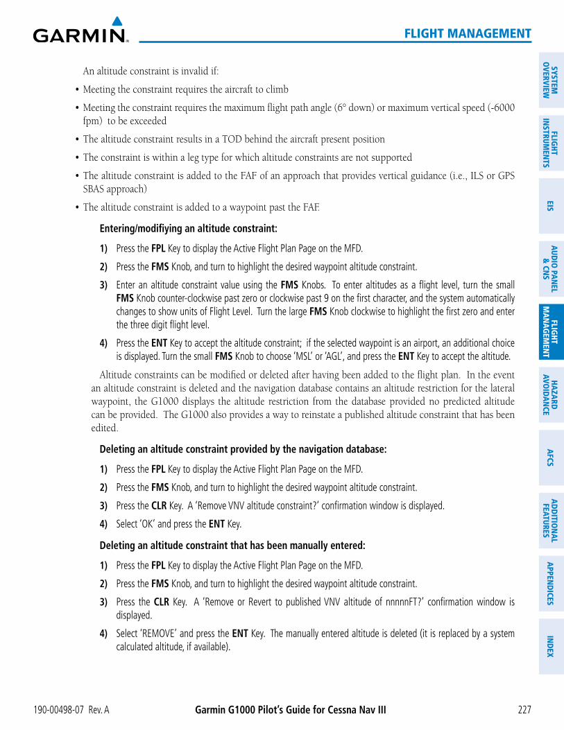
190-00498-07 Rev. A Garmin G1000 Pilot’s Guide for Cessna Nav III 227
FLIGHT MANAGEMENT
SYSTEMO
VERVIEWFLIG
HTIN
STRUMEN
TSEIS
AUDIO
PANEL
& CN
SFLIG
HTM
ANAG
EMEN
THAZARD
AVOIDAN
CEAFCS
ADD
ITION
ALFEATURES
APPEND
ICESIN
DEX
An altitude constraint is invalid if:
fpm) to be exceeded
SBAS approach)
Entering/modifiying an altitude constraint:
1) Press the FPL Key to display the Active Flight Plan Page on the MFD.
2) Press the FMS Knob, and turn to highlight the desired waypoint altitude constraint.
3) Enter an altitude constraint value using the FMS Knobs. To enter altitudes as a flight level, turn the small FMS Knob counter-clockwise past zero or clockwise past 9 on the first character, and the system automatically changes to show units of Flight Level. Turn the large FMS Knob clockwise to highlight the first zero and enter the three digit flight level.
4) Press the ENT Key to accept the altitude constraint; if the selected waypoint is an airport, an additional choice is displayed. Turn the small FMS Knob to choose ‘MSL’ or ‘AGL’, and press the ENT Key to accept the altitude.
Altitude constraints can be modified or deleted after having been added to the flight plan. In the event an altitude constraint is deleted and the navigation database contains an altitude restriction for the lateral waypoint, the G1000 displays the altitude restriction from the database provided no predicted altitude can be provided. The G1000 also provides a way to reinstate a published altitude constraint that has been edited.
Deleting an altitude constraint provided by the navigation database:
1) Press the FPL Key to display the Active Flight Plan Page on the MFD.
2) Press the FMS Knob, and turn to highlight the desired waypoint altitude constraint.
3) Press the CLR Key. A ‘Remove VNV altitude constraint?’ confirmation window is displayed.
4) Select ‘OK’ and press the ENT Key.
Deleting an altitude constraint that has been manually entered:
1) Press the FPL Key to display the Active Flight Plan Page on the MFD.
2) Press the FMS Knob, and turn to highlight the desired waypoint altitude constraint.
3) Press the CLR Key. A ‘Remove or Revert to published VNV altitude of nnnnnFT?’ confirmation window is displayed.
4) Select ‘REMOVE’ and press the ENT Key. The manually entered altitude is deleted (it is replaced by a system calculated altitude, if available).
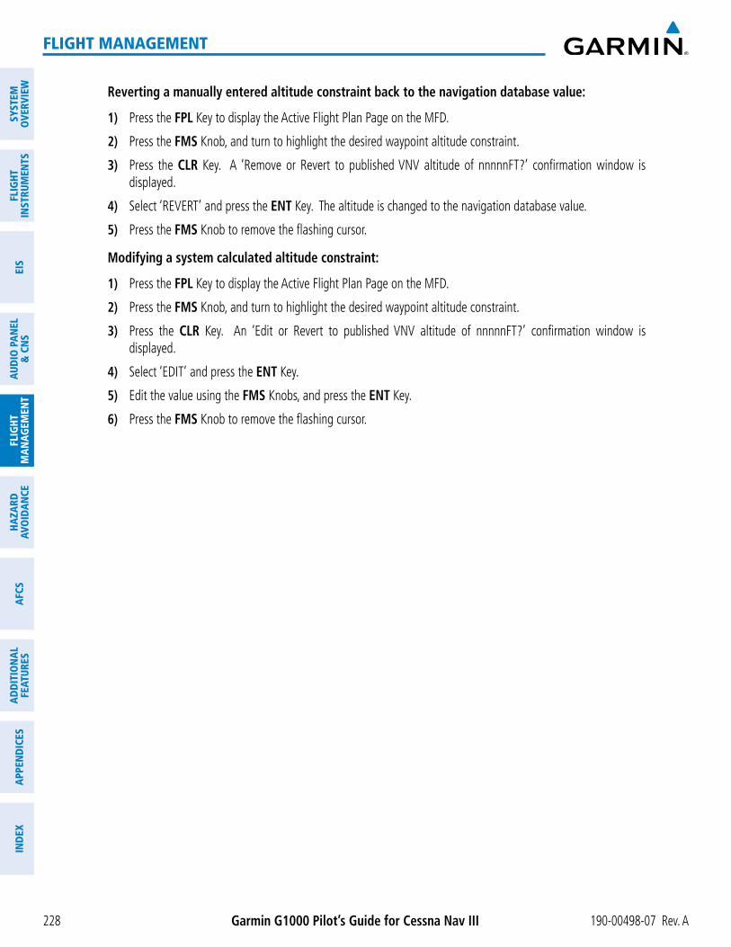
Garmin G1000 Pilot’s Guide for Cessna Nav III 190-00498-07 Rev. A228
FLIGHT MANAGEMENT
SYST
EMO
VERV
IEW
FLIG
HTIN
STRU
MEN
TSEI
SAU
DIO
PAN
EL&
CN
SFL
IGHT
MAN
AGEM
ENT
HAZA
RDAV
OID
ANCE
AFCS
ADD
ITIO
NAL
FEAT
URES
APPE
ND
ICES
IND
EX
Reverting a manually entered altitude constraint back to the navigation database value:
1) Press the FPL Key to display the Active Flight Plan Page on the MFD.
2) Press the FMS Knob, and turn to highlight the desired waypoint altitude constraint.
3) Press the CLR Key. A ‘Remove or Revert to published VNV altitude of nnnnnFT?’ confirmation window is displayed.
4) Select ‘REVERT’ and press the ENT Key. The altitude is changed to the navigation database value.
5) Press the FMS Knob to remove the flashing cursor.
Modifying a system calculated altitude constraint:
1) Press the FPL Key to display the Active Flight Plan Page on the MFD.
2) Press the FMS Knob, and turn to highlight the desired waypoint altitude constraint.
3) Press the CLR Key. An ‘Edit or Revert to published VNV altitude of nnnnnFT?’ confirmation window is displayed.
4) Select ‘EDIT’ and press the ENT Key.
5) Edit the value using the FMS Knobs, and press the ENT Key.
6) Press the FMS Knob to remove the flashing cursor.

190-00498-07 Rev. A Garmin G1000 Pilot’s Guide for Cessna Nav III 229
FLIGHT MANAGEMENT
SYSTEMO
VERVIEWFLIG
HTIN
STRUMEN
TSEIS
AUDIO
PANEL
& CN
SFLIG
HTM
ANAG
EMEN
THAZARD
AVOIDAN
CEAFCS
ADD
ITION
ALFEATURES
APPEND
ICESIN
DEX
5.8 PROCEDURES
The G1000 can access the whole range of instrument procedures available. Departures (DPs), arrivals (STARs), and non-precision and precision approaches (APPRs) are stored within the database and can be loaded using the Procedures (PROC) Key.
The selected procedure for the departure or arrival airport is added to the active flight plan. No waypoints are
loaded, the procedure loading window defaults to the appropriate airport, saving some time selecting the correct airport on the Procedure Loading Page. Whenever an approach is selected, the choice to either “load” or “activate” is given. “Loading” adds the approach to the end of the flight plan without immediately using it for navigation guidance. This allows continued navigation via the intermediate waypoints in the original flight plan, but keeps
the procedure to the end of the flight plan but immediately begins to provide guidance to the first waypoint in the approach.
DEPARTURESA Departure Procedure (DP) is loaded at the departure airport in the flight plan. Only one departure can be
loaded at a time in a flight plan. If a departure is loaded when another departure is already in the active flight plan, the new departure replaces the previous departure. The route is defined by selection of a departure, the transition waypoints, and a runway.
LOADING A DEPARTURE INTO THE ACTIVE FLIGHT PLAN
Loading a departure into the active flight plan using the PROC Key:
1) Press the PROC Key. The Procedures Window is displayed.
2) Highlight ‘SELECT DEPARTURE’.
3) Press the ENT Key. The Departure Loading Page is displayed.
4) Use the FMS Knob to select an airport and press the ENT Key.
5) Select a departure from the list and press the ENT Key.
6) Select a runway (if required) and press the ENT Key.
7) Select a transition (if required) and press the ENT Key. ‘LOAD?’ is highlighted.
8) Press the ENT Key to load the departure procedure.
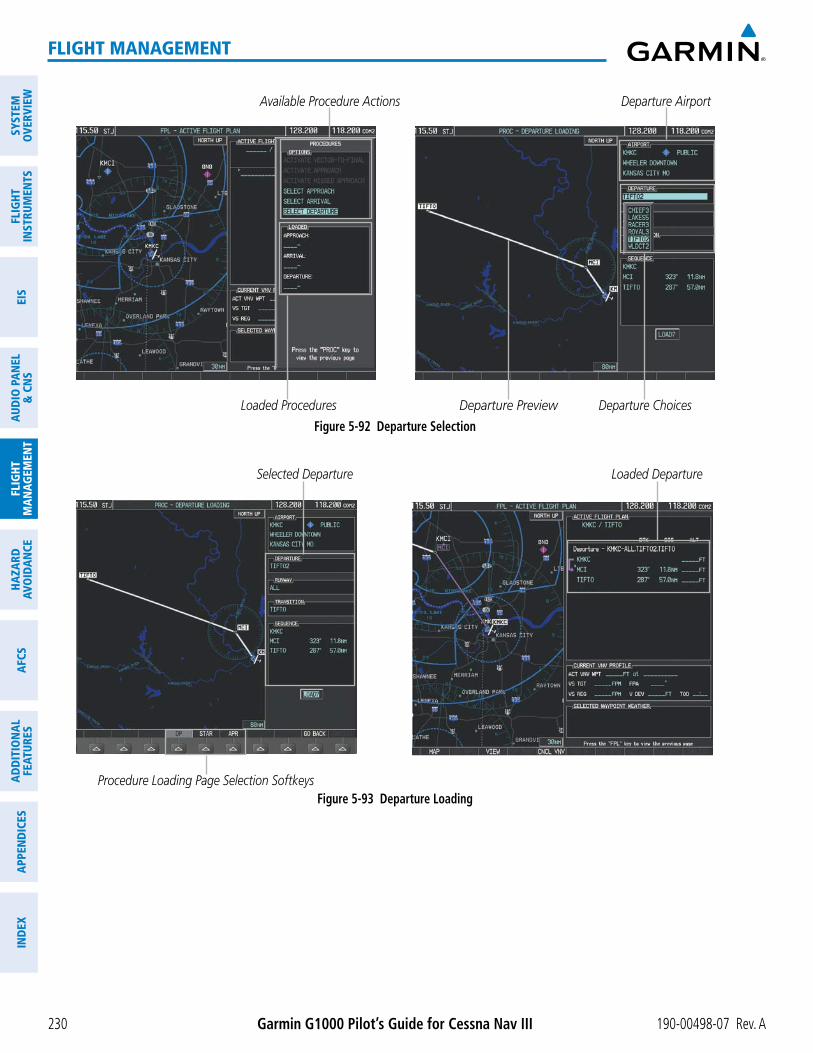
Garmin G1000 Pilot’s Guide for Cessna Nav III 190-00498-07 Rev. A230
FLIGHT MANAGEMENT
SYST
EMO
VERV
IEW
FLIG
HTIN
STRU
MEN
TSEI
SAU
DIO
PAN
EL&
CN
SFL
IGHT
MAN
AGEM
ENT
HAZA
RDAV
OID
ANCE
AFCS
ADD
ITIO
NAL
FEAT
URES
APPE
ND
ICES
IND
EX
Figure 5-92 Departure Selection
Departure Airport
Departure Preview
Available Procedure Actions
Departure ChoicesLoaded Procedures
Procedure Loading Page Selection SoftkeysFigure 5-93 Departure Loading
Loaded DepartureSelected Departure

190-00498-07 Rev. A Garmin G1000 Pilot’s Guide for Cessna Nav III 231
FLIGHT MANAGEMENT
SYSTEMO
VERVIEWFLIG
HTIN
STRUMEN
TSEIS
AUDIO
PANEL
& CN
SFLIG
HTM
ANAG
EMEN
THAZARD
AVOIDAN
CEAFCS
ADD
ITION
ALFEATURES
APPEND
ICESIN
DEX
Viewing available departures at an airport:
1) From the Airport Information Page (first page in the WPT group), press the DP Softkey. The Departure Information Page is displayed, defaulting to the airport displayed on the Airport information Page.
2) To select another airport, press the FMS Knob to activate the cursor, enter an identifier/facility name/city, and press the ENT Key.
3) Turn the large FMS Knob to highlight the Departure. The departure is previewed on the map.
4) Turn the small FMS Knob to view the available departures. Press the ENT Key to select the departure. The cursor moves to the Runway box. The departure is previewed on the map.
5) Turn the small FMS Knob to view the available runways. Press the ENT Key to select the runway. The cursor moves to the Transition box (only if there are available transitions). The departure is previewed on the map.
6) Turn the small FMS Knob to view the available transitions. Press the ENT Key to select the transition. The cursor moves to the Sequence box. The departure is previewed on the map.
7) Press the INFO-x Softkey to return to the Airport Information Page.
REMOVING A DEPARTURE FROM THE ACTIVE FLIGHT PLANWhen plans change while flying IFR, departures can be easily removed from the Active Flight Plan.
Removing a departure procedure from the active flight plan:
1) Press the FPL Key to display the Active Flight Plan Page (MFD) or the Active Flight Plan Window (PFD)
2) Press the MENU Key, and highlight ‘Remove Departure’.
3) Press the ENT Key. A confirmation window is displayed listing the departure procedure.
4) With ‘OK’ highlighted, press the ENT Key. To cancel the removal request, highlight ‘CANCEL’ and press the ENT Key.
Or:
1) Press the FPL Key to display the Active Flight Plan Page (MFD) or the Active Flight Plan Window (PFD)
2) Press the FMS Knob, and turn to highlight the departure header in the active flight plan.
3) Press the CLR Key. A confirmation window is displayed listing the departure procedure.
4) With ‘OK’ highlighted, press the ENT Key. To cancel the removal request, highlight ‘CANCEL’ and press the ENT Key.
5) Press the FMS Knob to remove the flashing cursor.

Garmin G1000 Pilot’s Guide for Cessna Nav III 190-00498-07 Rev. A232
FLIGHT MANAGEMENT
SYST
EMO
VERV
IEW
FLIG
HTIN
STRU
MEN
TSEI
SAU
DIO
PAN
EL&
CN
SFL
IGHT
MAN
AGEM
ENT
HAZA
RDAV
OID
ANCE
AFCS
ADD
ITIO
NAL
FEAT
URES
APPE
ND
ICES
IND
EX
ARRIVALS A Standard Terminal Arrival (STAR) can be loaded at any airport that has one available. Only one arrival
can be loaded at a time in a flight plan. If an arrival is loaded when another arrival is already in the active flight plan, the new arrival replaces the previous arrival. The route is defined by selection of an arrival, the transition waypoints, and a runway.
LOADING AN ARRIVAL INTO THE ACTIVE FLIGHT PLAN
Loading an arrival into the active flight plan using the PROC Key:
1) Press the PROC Key. The Procedures Window is displayed.
2) Highlight ‘SELECT ARRIVAL’.
3) Press the ENT Key. The Arrival Loading Page is displayed.
4) Use the FMS Knob to select an airport and press the ENT Key.
5) Select an arrival from the list and press the ENT Key.
6) Select a transition (if required) and press the ENT Key.
7) Select a runway (if required) and press the ENT Key. ‘LOAD?’ is highlighted.
8) Press the ENT Key to load the arrival procedure.
Figure 5-94 Arrival Selection
Destination Airport
Arrival Preview
Available Procedure Actions
Arrival ChoicesLoaded Procedures
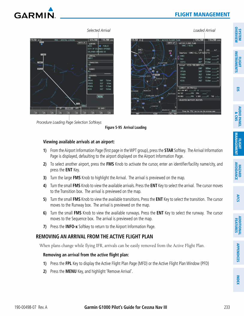
190-00498-07 Rev. A Garmin G1000 Pilot’s Guide for Cessna Nav III 233
FLIGHT MANAGEMENT
SYSTEMO
VERVIEWFLIG
HTIN
STRUMEN
TSEIS
AUDIO
PANEL
& CN
SFLIG
HTM
ANAG
EMEN
THAZARD
AVOIDAN
CEAFCS
ADD
ITION
ALFEATURES
APPEND
ICESIN
DEX
Procedure Loading Page Selection SoftkeysFigure 5-95 Arrival Loading
Loaded ArrivalSelected Arrival
Viewing available arrivals at an airport:
1) From the Airport Information Page (first page in the WPT group), press the STAR Softkey. The Arrival Information Page is displayed, defaulting to the airport displayed on the Airport Information Page.
2) To select another airport, press the FMS Knob to activate the cursor, enter an identifier/facility name/city, and press the ENT Key.
3) Turn the large FMS Knob to highlight the Arrival. The arrival is previewed on the map.
4) Turn the small FMS Knob to view the available arrivals. Press the ENT Key to select the arrival. The cursor moves to the Transition box. The arrival is previewed on the map.
5) Turn the small FMS Knob to view the available transitions. Press the ENT Key to select the transition. The cursor moves to the Runway box. The arrival is previewed on the map.
6) Turn the small FMS Knob to view the available runways. Press the ENT Key to select the runway. The cursor moves to the Sequence box. The arrival is previewed on the map.
7) Press the INFO-x Softkey to return to the Airport Information Page.
REMOVING AN ARRIVAL FROM THE ACTIVE FLIGHT PLANWhen plans change while flying IFR, arrivals can be easily removed from the Active Flight Plan.
Removing an arrival from the active flight plan:
1) Press the FPL Key to display the Active Flight Plan Page (MFD) or the Active Flight Plan Window (PFD)
2) Press the MENU Key, and highlight ‘Remove Arrival’.

Garmin G1000 Pilot’s Guide for Cessna Nav III 190-00498-07 Rev. A234
FLIGHT MANAGEMENT
SYST
EMO
VERV
IEW
FLIG
HTIN
STRU
MEN
TSEI
SAU
DIO
PAN
EL&
CN
SFL
IGHT
MAN
AGEM
ENT
HAZA
RDAV
OID
ANCE
AFCS
ADD
ITIO
NAL
FEAT
URES
APPE
ND
ICES
IND
EX
3) Press the ENT Key. A confirmation window is displayed listing the arrival procedure.
4) With ‘OK’ highlighted, press the ENT Key. To cancel the removal request, highlight ‘CANCEL’ and press the ENT Key.
Or:
1) Press the FPL Key to display the Active Flight Plan Page (MFD) or the Active Flight Plan Window (PFD)
2) Press the FMS Knob, and turn to highlight the arrival header in the active flight plan.
3) Press the CLR Key. A confirmation window is displayed listing the arrival procedure.
4) With ‘OK’ highlighted, press the ENT Key. To cancel the removal request, highlight ‘CANCEL’ and press the ENT Key.
5) Press the FMS Knob to remove the flashing cursor.
APPROACHES
NOTE: If certain GPS parameters (SBAS, RAIM, etc.) are not available, some published approach procedures for the desired airport may not be displayed in the list of available approaches.
An Approach Procedure (APPR) can be loaded at any airport that has one available, and provides guidance for non-precision and precision approaches to airports with published instrument approach procedures. Only one approach can be loaded at a time in a flight plan. If an approach is loaded when another approach is already in the active flight plan, the new approach replaces the previous approach. The route is defined by selection of an approach and the transition waypoints.
Whenever an approach is selected, the choice to either “load” or “activate” is given. “Loading” adds the approach to the end of the flight plan without immediately using it for navigation guidance. This allows continued navigation via the intermediate waypoints in the original flight plan, but keeps the procedure
procedure to the end of the flight plan but immediately begins to provide guidance to the first waypoint in the approach.
When selecting an approach, a “GPS” designation to the right of the procedure name indicates the procedure can be flown using the GPS receiver. Some procedures do not have this designation, meaning the GPS receiver can be used for supplemental navigation guidance only. If the GPS receiver cannot be used for primary guidance, the appropriate navigation receiver must be used for the selected approach (e.g., VOR or ILS). The final course segment of ILS approaches, for example, must be flown by tuning the NAV receiver to
CDI.

190-00498-07 Rev. A Garmin G1000 Pilot’s Guide for Cessna Nav III 235
FLIGHT MANAGEMENT
SYSTEMO
VERVIEWFLIG
HTIN
STRUMEN
TSEIS
AUDIO
PANEL
& CN
SFLIG
HTM
ANAG
EMEN
THAZARD
AVOIDAN
CEAFCS
ADD
ITION
ALFEATURES
APPEND
ICESIN
DEX
The G1000 SBAS GPS allows for flying LNAV, LNAV/VNAV, and LPV approaches according to the published chart. LNAV+V is a standard LNAV approach with advisory vertical guidance provided for assistance in maintaining a constant vertical glidepath similar to an ILS glideslope on approach. This guidance is displayed on the G1000 PFD in the same location as the ILS glideslope using a magenta diamond. In all cases where LNAV+V is indicated by the system during an approach, LNAV minima are used. The active approach type is annunciated on the HSI as shown in the following table:
HSI Annunciation Description Example on HSILNAV GPS approach using published LNAV
minima
Approach Type - LNAV - LNAV+V - L/VNAV - LPV
LNAV+V GPS approach using published LNAV minima. Advisory vertical guidance is provided
L/VNAV(available only if SBAS equipped)
GPS approach using published LNAV/VNAV minima
LPV(available only if SBAS equipped
GPS approach using published LPV minima
Table 5-9 Approach Types
LOADING AN APPROACH INTO THE ACTIVE FLIGHT PLAN
Loading an approach into the active flight plan using the PROC Key:
1) Press the PROC Key. The Procedures Window is displayed.
2) Highlight ‘SELECT APPROACH’, and press the ENT Key. The Approach Loading Page is displayed.
3) Use the FMS Knob to select an airport and press the ENT Key.
4) Select an approach from the list and press the ENT Key.
5) Select a transition (if required) and press the ENT Key.
6) Barometric Minimums
a) To set ‘MINIMUMS’, turn the small FMS Knob to select ‘BARO’, and press the ENT Key. Turn the small FMS Knob to select the altitude, and press the ENT Key.
Or:
b) To skip setting minimums, press the ENT Key.
7) Press the ENT Key with ‘LOAD?’ highlighted to load the approach procedure; or turn the large FMS Knob to highlight ‘ACTIVATE’ and press the ENT Key to load and activate the approach procedure.
NOTE: When GPS is not approved for the selected final approach course, the message ‘NOT APPROVED FOR GPS’ is displayed. GPS provides guidance to the approach, but the HSI must to be switched to a NAV receiver to fly the final course of the approach.

Garmin G1000 Pilot’s Guide for Cessna Nav III 190-00498-07 Rev. A236
FLIGHT MANAGEMENT
SYST
EMO
VERV
IEW
FLIG
HTIN
STRU
MEN
TSEI
SAU
DIO
PAN
EL&
CN
SFL
IGHT
MAN
AGEM
ENT
HAZA
RDAV
OID
ANCE
AFCS
ADD
ITIO
NAL
FEAT
URES
APPE
ND
ICES
IND
EX
Figure 5-96 Approach Selection
Destination Airport
Approach Preview
Available Procedure Actions
Approach ChoicesLoaded Procedures
Procedure Loading Page Selection SoftkeysFigure 5-97 Approach Loading
Loaded ApproachSelected Approach
Viewing available approaches at an airport:
1) From the Airport Information Page (first page in the WPT group), press the APR Softkey. The Approach Information Page is displayed, defaulting to the airport displayed on the Airport information Page.
2) To select another airport, press the FMS Knob to activate the cursor, enter an identifier/facility name/city, and press the ENT Key.

190-00498-07 Rev. A Garmin G1000 Pilot’s Guide for Cessna Nav III 237
FLIGHT MANAGEMENT
SYSTEMO
VERVIEWFLIG
HTIN
STRUMEN
TSEIS
AUDIO
PANEL
& CN
SFLIG
HTM
ANAG
EMEN
THAZARD
AVOIDAN
CEAFCS
ADD
ITION
ALFEATURES
APPEND
ICESIN
DEX
3) Press the FMS Knob, then turn the large FMS Knob to highlight the Approach. The approach is previewed on the map.
4) Turn the small FMS Knob to view the available approaches. Press the ENT Key to select the approach. The cursor moves to the Transition box. The approach is previewed on the map.
5) Turn the small FMS Knob to view the available transitions. Press the ENT Key to select the transition. The cursor moves to the Minimums box. The approach is previewed on the map.
6) Turn the small FMS Knob to select BARO (or optional RAD ALT) minimums on or off. Press the ENT Key.
a) When minimums are selected on, the cursor moves to the minimum altitude field . Use the small FMS Knob to select the altitude. Press the ENT Key. The cursor moves to the Sequence box. The approach is previewed on the map.
Or:
b) When minimums are selected off, the cursor moves to the Sequence box. The approach is previewed on the map.
7) Press the INFO-x Softkey to return to the Airport Information Page.
Loading an approach into the active flight plan from the Nearest Airport Page:
1) Select the Nearest Airports Page.
2) Press the FMS Knob, then turn the large FMS Knob to highlight the desired nearest airport. The airport is previewed on the map.
3) Press the APR Softkey; or press the MENU Key, highlight ‘Select Approach Window’, and press the ENT Key.
4) Turn the FMS Knob to highlight the desired approach.
5) Press the LD APR Softkey; or press the MENU Key, highlight ‘Load Approach’, and press the ENT Key. The Approach Loading Page is displayed with the transitions field highlighted.
6) Turn the FMS Knob to highlight the desired transition, and press the ENT Key.
7) Barometric Minimums
a) To set ‘MINIMUMS’, turn the small FMS Knob to select ‘BARO’, and press the ENT Key. Turn the small FMS Knob to select the altitude, and press the ENT Key. The ‘LOAD?’ field is highlighted.
Or:
b) To skip setting minimums, press the ENT Key. The ‘LOAD?’ field is highlighted.
8) Press the ENT Key with ‘LOAD?’ highlighted to load the approach procedure; or turn the large FMS Knob to highlight ‘ACTIVATE’ and press the ENT Key to load and activate the approach procedure. The G1000 continues navigating the current flight plan until the approach is activated. When GPS is not approved for the selected final approach course, the message ‘NOT APPROVED FOR GPS’ is displayed. GPS provides guidance to the approach, but the HSI must to be switched to a NAV receiver to fly the final course of the approach.

Garmin G1000 Pilot’s Guide for Cessna Nav III 190-00498-07 Rev. A238
FLIGHT MANAGEMENT
SYST
EMO
VERV
IEW
FLIG
HTIN
STRU
MEN
TSEI
SAU
DIO
PAN
EL&
CN
SFL
IGHT
MAN
AGEM
ENT
HAZA
RDAV
OID
ANCE
AFCS
ADD
ITIO
NAL
FEAT
URES
APPE
ND
ICES
IND
EX
ACTIVATING AN APPROACHA previously loaded approach can be activated from the Procedures Window.
Activating a previously loaded approach:
1) Press the PROC Key. The Procedures Window is displayed with ‘Activate Approach’ highlighted.
2) Press the ENT Key to activate the approach.
In many cases, it may be easiest to “load” the full approach while still some distance away, enroute to the
makes the inbound course to the FAF waypoint active.
Activating a previously loaded approach with vectors to final:
1) Press the PROC Key to display the Procedures Window.
2) Highlight ‘ACTIVATE VECTOR-TO-FINAL’ and press the ENT Key.
Loading and activating an approach using the MENU Key:
1) From the Approach Loading Page, press the MENU Key. The page menu is displayed with ‘Load & Activate Approach’ highlighted.
2) Press the ENT Key. When GPS is not approved for the selected final approach course, the message ‘NOT APPROVED FOR GPS’ is displayed. GPS provides guidance to the approach, but the HSI must to be switched to a NAV receiver to fly the final course of the approach.
REMOVING AN APPROACH FROM THE ACTIVE FLIGHT PLANWhen plans change while flying IFR, approaches can be easily removed from the Active Flight Plan.
Removing an approach from the active flight plan:
1) Press the FPL Key to display the Active Flight Plan Page (MFD) or the Active Flight Plan Window (PFD)
2) Press the MENU Key, and highlight ‘Remove Approach’.
3) Press the ENT Key. A confirmation window is displayed listing the approach procedure.
4) With ‘OK’ highlighted, press the ENT Key. To cancel the removal, highlight ‘CANCEL’ and press the ENT Key.
Or:
1) Press the FPL Key to display the Active Flight Plan Page (MFD) or the Active Flight Plan Window (PFD)
2) Press the FMS Knob, and turn to highlight the approach header in the active flight plan.
3) Press the CLR Key. A confirmation window is displayed listing the approach procedure.
4) With ‘OK’ highlighted, press the ENT Key. To cancel the removal, highlight ‘CANCEL’ and press the ENT Key.
5) Press the FMS Knob to remove the flashing cursor.

190-00498-07 Rev. A Garmin G1000 Pilot’s Guide for Cessna Nav III 239
FLIGHT MANAGEMENT
SYSTEMO
VERVIEWFLIG
HTIN
STRUMEN
TSEIS
AUDIO
PANEL
& CN
SFLIG
HTM
ANAG
EMEN
THAZARD
AVOIDAN
CEAFCS
ADD
ITION
ALFEATURES
APPEND
ICESIN
DEX
MISSED APPROACH
Activating a missed approach in the active flight plan:
1) Press the PROC Key.
2) Turn the FMS Knob to highlight ‘ACTIVATE MISSED APPROACH’.
3) Press the ENT Key. The aircraft automatically sequences to the MAHP.
Or:
Press the Go-Around Button.
COURSE TO ALTITUDE
not part of the published procedure. It is simply a Course to Altitude (CA) leg which guides the aircraft along
this approach. In this case, if the aircraft altitude is below the specified altitude (6,368 feet) after crossing the MAP, a direct-to is established to provide a course on runway heading until an altitude of 6,368 feet is reached. After reaching 6,368 feet, a direct-to is established to the published MAHP (in this case MOGAL). If the aircraft altitude is above the specified altitude after crossing the MAP, a direct-to is established to the published fix (MOGAL) to begin the missed approach procedure.
In some missed approach procedures this Course to Altitude leg may be part of the published procedure. For example, a procedure may dictate a climb to 5,500 feet, then turn left and proceed to the Missed Approach
aircraft altitude is lower than the prescribed altitude, a direct-to is established on a Course to Altitude leg when the missed approach procedure is activated.
Figure 5-98 Course to Altitude
Course to Altitude Leg

Garmin G1000 Pilot’s Guide for Cessna Nav III 190-00498-07 Rev. A240
FLIGHT MANAGEMENT
SYST
EMO
VERV
IEW
FLIG
HTIN
STRU
MEN
TSEI
SAU
DIO
PAN
EL&
CN
SFL
IGHT
MAN
AGEM
ENT
HAZA
RDAV
OID
ANCE
AFCS
ADD
ITIO
NAL
FEAT
URES
APPE
ND
ICES
IND
EX
5.9 TRIP PLANNING
The G1000 allows the pilot to view trip planning information, fuel information, and other information for a specified flight plan or flight plan leg based on automatic data, or based on manually entered data. Weight planning is also available, based on fuel sensor data and the active flight plan (to estimate remaining fuel).
TRIP PLANNINGAll of the input of data needed for calculation and viewing of the statistics is done on the Trip Planning Page
Figure 5-99 Trip Planning Page
Trip StatisticsDesired Track -
Distance -Est. Time Enroute -
Est. Time of Arrival -Enroute Safe Altitude -
Sunrise Time (local) -Sunset Time (local) -
Trip Input Data (sensor/pilot) - Departure Time (local) - Ground Speed - Fuel Flow - Fuel On Board Aircraft - Calibrated Airspeed - Indicated Altitude - Barometric Pressure - Total Air Temperature
Softkeys - Automatic/Manual Page Mode - Flight Plan/Waypoint Mode
Preview of Selected Flight Plan/
Flight Plan Leg
Trip Planning Page Mode - Automatic/Manual
Selected Flight Plan Segment- FPL Number/Cumulative Legs (CUM or REM) or Leg Number (NN)
- Waypoints Defining Selected Flight Plan/Flight Plan Leg
Fuel StatisticsEfficiency -
Total Endurance -Remaining Fuel -
Remaining Endurance -Fuel Required -
Total Range -
Other Statistics - Density Altitude - True Airspeed (TAS)
The trip planning inputs are based on sensor inputs (automatic page mode) or on pilot inputs (manual page mode). Some additional explanation of the sources for some of the inputs is as follows:
Departure time (DEP TIME) - This defaults to the current time in automatic page mode. The computations are from the aircraft present position, so the aircraft is always just departing.
Calibrated airspeed (CALIBRATED AS) - The primary source is from the air data system, and the secondary source of information is GPS ground speed.
Indicated altitude (IND ALTITUDE) - The primary source is the barometric altitude, and the secondary source of information is GPS altitude.

190-00498-07 Rev. A Garmin G1000 Pilot’s Guide for Cessna Nav III 241
FLIGHT MANAGEMENT
SYSTEMO
VERVIEWFLIG
HTIN
STRUMEN
TSEIS
AUDIO
PANEL
& CN
SFLIG
HTM
ANAG
EMEN
THAZARD
AVOIDAN
CEAFCS
ADD
ITION
ALFEATURES
APPEND
ICESIN
DEX
TRIP STATISTICSThe trip statistics are calculated based on the selected starting and ending waypoints and the trip planning
inputs.
In flight plan mode (FPL) with a stored flight plan selected (NN), and the entire flight plan (CUM) selected, the waypoints are the starting and ending waypoints of the selected flight plan.
In flight plan mode (FPL) with a stored flight plan selected (NN), and a specific leg (NN) selected, the waypoints are the endpoints of the selected leg.
In flight plan mode (FPL) with the active flight plan selected (00), and the remaining flight plan (REM)
active flight plan.
In flight plan mode (FPL) with the active flight plan selected (00), and a specific leg (NN) selected, the
In waypoint (WPTS) mode these are manually selected waypoints (if there is an active flight plan, these default to the endpoints of the active leg).
Some of the calculated trip statistics are dashed when the selected leg of the active flight plan has already been flown.
It is dashed unless only a single leg is selected.
as minutes:seconds.
destination.
- If in waypoint mode then the ETA is the ETE added to the departure time.
- If a flight plan other than the active flight plan is selected it shows the ETA by adding to the departure time all of the ETEs of the legs up to the selected leg. If the entire flight plan is selected, then the ETA is calculated as if the last leg of the flight plan was selected.
- If the active flight plan is selected the ETA reflects the current position of the aircraft and the current leg being flown. The ETA is calculated by adding to the current time the ETEs of the current leg up to and including the selected leg. If the entire flight plan is selected, then the ETA is calculated as if the last leg of the flight plan was selected.
sunrise and sunset times (SUNRISE, SUNSET) - These times are shown as hours:minutes and are the local time at the destination.

Garmin G1000 Pilot’s Guide for Cessna Nav III 190-00498-07 Rev. A242
FLIGHT MANAGEMENT
SYST
EMO
VERV
IEW
FLIG
HTIN
STRU
MEN
TSEI
SAU
DIO
PAN
EL&
CN
SFL
IGHT
MAN
AGEM
ENT
HAZA
RDAV
OID
ANCE
AFCS
ADD
ITIO
NAL
FEAT
URES
APPE
ND
ICES
IND
EX
FUEL STATISTICSThe fuel statistics are calculated based on the selected starting and ending waypoints and the trip planning
inputs. Some of the calculated trip statistics are dashed when the selected leg of the active flight plan has already been flown.
current fuel flow.
fuel endurance (TOTAL ENDUR) - This time is shown as hours:minutes. This value is obtained by dividing the amount of fuel on board by the current fuel flow.
REM FUEL) - This value is calculated by taking the
of fuel endurance and subtracting the estimated time enroute to the end of the selected leg.
flow.
fuel endurance by the ground speed.
OTHER STATISTICSThese statistics are calculated based on the system sensor inputs or the manual trip planning inputs.
True airspeed (TRUE AIRSPEED)
The pilot may select automatic (AUTO) or manual (MANUAL) page mode, and flight plan (FPL) or waypoint (WPTS) mode. In automatic page mode, only the FPL, LEG, or waypoint IDs are editable (based on FPL/WPTS selection).
Figure 5-100 Trip Planning Page - Flight Plan Mode
Selected Leg(s)Stored Flight Plan - CUM: Beginning to End of FPL - NN: Beginning to End of Selected LegActive Flight Plan - REM: Pres. Pos. to End of FPL - NN: Pres. Pos. to End of Selected Leg
Starting and Ending Waypoint of Selected Flight Plan Segment
Selected Flight Plan NN -00 is Active FPL
01-99 are Stored FPLs
Figure 5-101 Trip Planning Page - Waypoint Mode
Selected Leg(s)Not Available
Selected Starting and Ending Waypoints
Selected Flight PlanNot Available

190-00498-07 Rev. A Garmin G1000 Pilot’s Guide for Cessna Nav III 243
FLIGHT MANAGEMENT
SYSTEMO
VERVIEWFLIG
HTIN
STRUMEN
TSEIS
AUDIO
PANEL
& CN
SFLIG
HTM
ANAG
EMEN
THAZARD
AVOIDAN
CEAFCS
ADD
ITION
ALFEATURES
APPEND
ICESIN
DEX
Selecting automatic or manual page mode:
Press the AUTO Softkey or the MANUAL Softkey; or press the MENU Key, highlight ‘Auto Mode’ or ‘Manual Mode’, and press the ENT Key.
Selecting flight plan or waypoint mode:
Press the FPL Softkey or the WPTS Softkey; or press the MENU Key, highlight ‘Flight Plan Mode’ or ‘Waypoints Mode’, and press the ENT Key.
Selecting a flight plan and leg for trip statistics:
1) Press the FMS Knob to activate the cursor in the flight plan number field.
2) Turn the small FMS Knob to select the desired flight plan number.
3) Turn the large FMS Knob to highlight ‘CUM’ or ‘REM’. The statistics for each leg can be viewed by turning the small FMS Knob to select the desired leg. The Inset Map also displays the selected data.
Selecting waypoints for waypoint mode:
1) Press the WPTS Softkey; or press the MENU Key, highlight ‘Waypoints Mode’, and press the ENT Key. The cursor is positioned in the waypoint field directly below the FPL field.
2) Turn the FMS knobs to select the desired waypoint (or select from the Page Menu ‘Set WPT to Present Position’ if that is what is desired), and press the ENT Key. The cursor moves to the second waypoint field.
3) Turn the FMS knobs to select the desired waypoint, and press the ENT Key. The statistics for the selected leg are displayed.
In manual page mode, the other eight trip input data fields must be entered by the pilot, in addition to flight plan and leg selection.
Entering manual data for trip statistics calculations:
1) Press the MANUAL Softkey or select ‘Manual Mode’ from the Page Menu, and press the ENT Key. The cursor may now be positioned in any field in the top right two boxes.
2) Turn the FMS Knobs to move the cursor onto the DEP TIME field and enter the desired value. Press the ENT Key. The statistics are calculated using the new value and the cursor moves to the next entry field. Repeat until all desired values have been entered.

Garmin G1000 Pilot’s Guide for Cessna Nav III 190-00498-07 Rev. A244
FLIGHT MANAGEMENT
SYST
EMO
VERV
IEW
FLIG
HTIN
STRU
MEN
TSEI
SAU
DIO
PAN
EL&
CN
SFL
IGHT
MAN
AGEM
ENT
HAZA
RDAV
OID
ANCE
AFCS
ADD
ITIO
NAL
FEAT
URES
APPE
ND
ICES
IND
EX
5.10 RAIM PREDICTION
RAIM (Receiver Autonomous Integrity Monitoring) is a GPS receiver function that performs a consistency check on all tracked satellites. RAIM ensures that the available satellite geometry allows the receiver to calculate a position within a specified RAIM protection limit (2.0 nm for oceanic, 2.0 nm for enroute, 1.0 nm for terminal, and 0.3 nm for non-precision approaches). During oceanic, enroute, and terminal phases of flight, RAIM is available nearly 100% of the time. The RAIM prediction function also indicates whether RAIM is available at a specified date and time. RAIM computations predict satellite coverage within ±15 min of the specified arrival date and time. Because of the tighter protection limit on approaches, there may be times when RAIM is not available. RAIM prediction must be initiated manually if there is concern over SBAS coverage at the destination or some other reason that compromises navigation precision. If RAIM is not predicted to be available for the final approach course, the approach does not become active. If RAIM is not available when crossing the FAF, the missed approach procedure must be flown.
Figure 5-102 RAIM Prediction
SBAS Softkey(displays SBAS Selection)
RAIM PREDICTION Box - Prediction Waypoint - Arrival Time - Arrival Date - RAIM Status
RAIM Softkey(displays RAIM PREDICTION)
Predicting RAIM availability at a selected waypoint:
1) Select the AUX-GPS Status Page.
2) Press the FMS Knob. The RAIM Prediction ‘WAYPOINT’ field is highlighted.
3) Turn the small FMS Knob to display the Waypoint Information Window. (Turning it clockwise displays a blank Waypoint Information Window, turning it counter-clockwise displays the Waypoint Information Window with a waypoint selection submenu allowing selection of active flight plan, nearest, recent, user, or airway waypoints).
4) Enter the identifier, facility, or city name of the departure waypoint; or select a waypoint from the submenu of waypoints and press the ENT Key to accept the waypoint entry.

190-00498-07 Rev. A Garmin G1000 Pilot’s Guide for Cessna Nav III 245
FLIGHT MANAGEMENT
SYSTEMO
VERVIEWFLIG
HTIN
STRUMEN
TSEIS
AUDIO
PANEL
& CN
SFLIG
HTM
ANAG
EMEN
THAZARD
AVOIDAN
CEAFCS
ADD
ITION
ALFEATURES
APPEND
ICESIN
DEX
5) Turn the FMS Knobs to enter an arrival time and press the ENT Key.
6) Turn the FMS Knobs to enter an arrival date and press the ENT Key.
7) Press the ENT Key with ‘COMPUTE RAIM?’ highlighted to begin the computation.
Predicting RAIM availability at the aircraft present position:
1) Select the AUX-GPS Status Page.
2) Press the FMS Knob. The RAIM Prediction ‘WAYPOINT’ field is highlighted.
3) Press the MENU Key, highlight ‘Set WPT to Present Position’, and press the ENT Key.
4) Press the ENT Key to accept the waypoint entry.
5) Turn the FMS Knobs to enter an arrival time and press the ENT Key.
6) Turn the FMS Knobs to enter an arrival date and press the ENT Key.
7) Press the ENT Key with ‘COMPUTE RAIM?’ highlighted to begin the computation.
Status of the RAIM computation for the selected waypoint, time, and date is displayed at the bottom of the RAIM PREDICTION Box as follows:
RAIM?’ - RAIM has not been computed.
RAIM calculation is in progress.
RAIM AVAILABLE’ - RAIM is predicted to be available.
RAIM NOT AVAILABLE’ - RAIM is predicted to be unavailable.
The Satellite Based Augmentation System (SBAS) provides increased navigation accuracy when available. SBAS can be enabled or disabled manually on the GPS Status Page.
Figure 5-103 SBAS Display - Active
SBAS Softkey(displays SBAS Selection)
SBAS SELECTION Box - EGNOS Enable/Disable - MSAS Enable/Disable - WAAS Enable/Disable
RAIM Softkey(displays RAIM PREDICTION)
SBAS Status
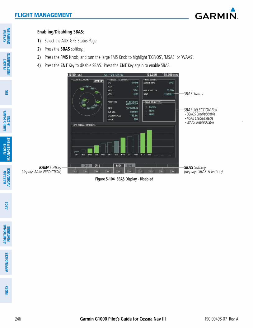
Garmin G1000 Pilot’s Guide for Cessna Nav III 190-00498-07 Rev. A246
FLIGHT MANAGEMENT
SYST
EMO
VERV
IEW
FLIG
HTIN
STRU
MEN
TSEI
SAU
DIO
PAN
EL&
CN
SFL
IGHT
MAN
AGEM
ENT
HAZA
RDAV
OID
ANCE
AFCS
ADD
ITIO
NAL
FEAT
URES
APPE
ND
ICES
IND
EX
Enabling/Disabling SBAS:
1) Select the AUX-GPS Status Page.
2) Press the SBAS softkey.
3) Press the FMS Knob, and turn the large FMS Knob to highlight ‘EGNOS’, ‘MSAS’ or ‘WAAS’.
4) Press the ENT Key to disable SBAS. Press the ENT Key again to enable SBAS.
Figure 5-104 SBAS Display - Disabled
SBAS Softkey(displays SBAS Selection)
SBAS SELECTION Box - EGNOS Enable/Disable - MSAS Enable/Disable - WAAS Enable/Disable
RAIM Softkey(displays RAIM PREDICTION)
SBAS Status

190-00498-07 Rev. A Garmin G1000 Pilot’s Guide for Cessna Nav III 247
FLIGHT MANAGEMENT
SYSTEMO
VERVIEWFLIG
HTIN
STRUMEN
TSEIS
AUDIO
PANEL
& CN
SFLIG
HTM
ANAG
EMEN
THAZARD
AVOIDAN
CEAFCS
ADD
ITION
ALFEATURES
APPEND
ICESIN
DEX
5.11 NAVIGATING A FLIGHT PLAN
The following discussion is an example of navigating a flight plan with an LPV approach using the SBAS capable GPS system while the G1000 provides vertical guidance through descents. A flight plan with an LNAV approach would be navigated in much the same way, but would not include vertical guidance when the final approach course is active.
NOTE: The following example flight plan is for instructional purposes only. All database information depicted should be considered not current.
The example is a flight plan from KMKC to KCOS filed using the TIFTO2 departure, various Victor Airways,
LPV (WAAS) approach selected for runway 35R, and a missed approach executed at the Missed Approach Point (MAP). A few enroute changes are demonstrated.
1) Prior to departure, the TIFTO2 departure, the airways, and the DBRY1 arrival at KCOS are loaded. See the Procedures section for loading departures and arrivals. Note the magenta arrow in Figure 5-105 indicating the active departure leg.
After takeoff, ATC assigns a heading of 240º.
2) Figure 5-105 shows the aircraft on the assigned heading of 240º. ‘TERM’ (Terminal) is the current CDI flight phase displayed on the HSI indicating 1.0 nm CDI scaling.
Figure 5-105 Assigned Heading of 240º

Garmin G1000 Pilot’s Guide for Cessna Nav III 190-00498-07 Rev. A248
FLIGHT MANAGEMENT
SYST
EMO
VERV
IEW
FLIG
HTIN
STRU
MEN
TSEI
SAU
DIO
PAN
EL&
CN
SFL
IGHT
MAN
AGEM
ENT
HAZA
RDAV
OID
ANCE
AFCS
ADD
ITIO
NAL
FEAT
URES
APPE
ND
ICES
IND
EX
3) ATC now assigns routing to join V4. A heading of 290º is assigned to intercept V4. The aircraft turns to heading 290° as seen in Figure 5-106.
Figure 5-106 Assigned Heading of 290º
4) Enter V4 into the flight plan.
a) Press the FMS Knob to activate the cursor.
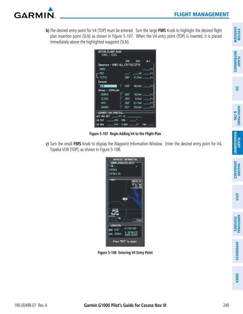
190-00498-07 Rev. A Garmin G1000 Pilot’s Guide for Cessna Nav III 249
FLIGHT MANAGEMENT
SYSTEMO
VERVIEWFLIG
HTIN
STRUMEN
TSEIS
AUDIO
PANEL
& CN
SFLIG
HTM
ANAG
EMEN
THAZARD
AVOIDAN
CEAFCS
ADD
ITION
ALFEATURES
APPEND
ICESIN
DEX
b) The desired entry point for V4 (TOP) must be entered. Turn the large FMS Knob to highlight the desired flight plan insertion point (SLN) as shown in Figure 5-107. When the V4 entry point (TOP) is inserted, it is placed immediately above the highlighted waypoint (SLN).
Figure 5-107 Begin Adding V4 to the Flight Plan
c) Turn the small FMS Knob to display the Waypoint Information Window. Enter the desired entry point for V4, Topeka VOR (TOP), as shown in Figure 5-108.
Figure 5-108 Entering V4 Entry Point

Garmin G1000 Pilot’s Guide for Cessna Nav III 190-00498-07 Rev. A250
FLIGHT MANAGEMENT
SYST
EMO
VERV
IEW
FLIG
HTIN
STRU
MEN
TSEI
SAU
DIO
PAN
EL&
CN
SFL
IGHT
MAN
AGEM
ENT
HAZA
RDAV
OID
ANCE
AFCS
ADD
ITIO
NAL
FEAT
URES
APPE
ND
ICES
IND
EX
d) Press the ENT Key. TOP is inserted into the flight plan as in Figure 5-109.
Figure 5-109 TOP Inserted into the Flight Plan
e) With SLN still highlighted as in Figure 5-109, turn the small FMS Knob clockwise. The Waypoint Information Page is displayed and the LD AIRWY Softkey is now available.
f) Press the LD AIRWY Softkey to display the list of available airways for TOP as seen in Figure 5-110.
Figure 5-110 List of Available Airways for TOP
g) Turn either FMS Knob to highlight V4 in the list as seen in Figure 5-110.
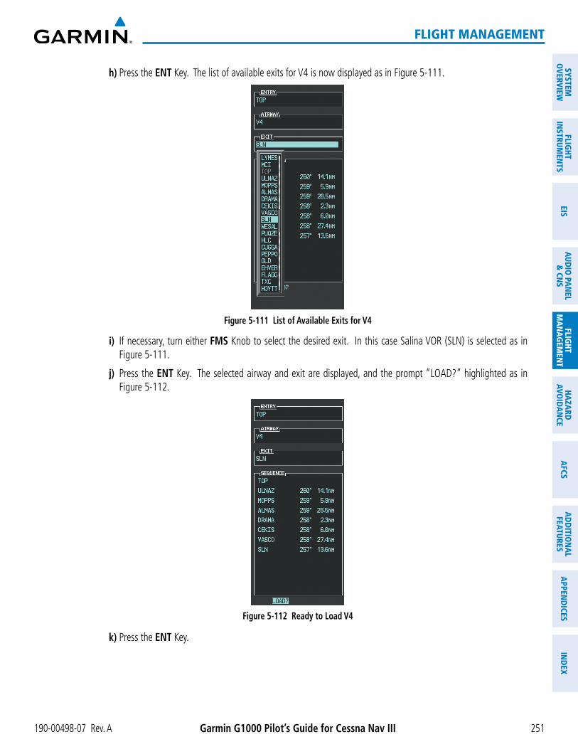
190-00498-07 Rev. A Garmin G1000 Pilot’s Guide for Cessna Nav III 251
FLIGHT MANAGEMENT
SYSTEMO
VERVIEWFLIG
HTIN
STRUMEN
TSEIS
AUDIO
PANEL
& CN
SFLIG
HTM
ANAG
EMEN
THAZARD
AVOIDAN
CEAFCS
ADD
ITION
ALFEATURES
APPEND
ICESIN
DEX
h) Press the ENT Key. The list of available exits for V4 is now displayed as in Figure 5-111.
Figure 5-111 List of Available Exits for V4
i) If necessary, turn either FMS Knob to select the desired exit. In this case Salina VOR (SLN) is selected as in Figure 5-111.
j) Press the ENT Key. The selected airway and exit are displayed, and the prompt “LOAD?” highlighted as in Figure 5-112.
Figure 5-112 Ready to Load V4
k) Press the ENT Key.

Garmin G1000 Pilot’s Guide for Cessna Nav III 190-00498-07 Rev. A252
FLIGHT MANAGEMENT
SYST
EMO
VERV
IEW
FLIG
HTIN
STRU
MEN
TSEI
SAU
DIO
PAN
EL&
CN
SFL
IGHT
MAN
AGEM
ENT
HAZA
RDAV
OID
ANCE
AFCS
ADD
ITIO
NAL
FEAT
URES
APPE
ND
ICES
IND
EX
l) V4 is now loaded into the flight plan as shown in Figure 5-113.
Figure 5-113 V4 is Loaded in the Flight Plan
5) Making V4 the active leg of the flight plan.
a) Press the FMS Knob to activate the cursor.
b) Turn the large FMS Knob to highlight ULNAZ. The TO waypoint of the leg is selected in order to activate the leg.
c) Press the ACT LEG Softkey. The confirmation window is now displayed as in Figure 5-114. Note the TOP to ULNAZ leg is actually part of V4.
Figure 5-114 Comfirm Active Leg

190-00498-07 Rev. A Garmin G1000 Pilot’s Guide for Cessna Nav III 253
FLIGHT MANAGEMENT
SYSTEMO
VERVIEWFLIG
HTIN
STRUMEN
TSEIS
AUDIO
PANEL
& CN
SFLIG
HTM
ANAG
EMEN
THAZARD
AVOIDAN
CEAFCS
ADD
ITION
ALFEATURES
APPEND
ICESIN
DEX
d) Verify the displayed leg is the desired leg and press the ENT Key. Note in Figure 5-115, the magenta arrow in the flight plan window and magenta line on the map indicating V4 is now the active flight plan leg. Note the phase of flight remained in Terminal (TERM) mode up to this point because a departure leg was active. Since a leg after the departure is now active, the current CDI flight phase is ENR (Enroute) and CDI scaling has changed to 2.0 nm.
Figure 5-115 V4 Now Active Leg
6) The aircraft continues on heading 290º. When crosstrack distance is less than 2.0 nm, the XTK disappears from the HSI and the CDI is positioned on the last dot indicating a 2.0 nm distance from the centerline of the next course.
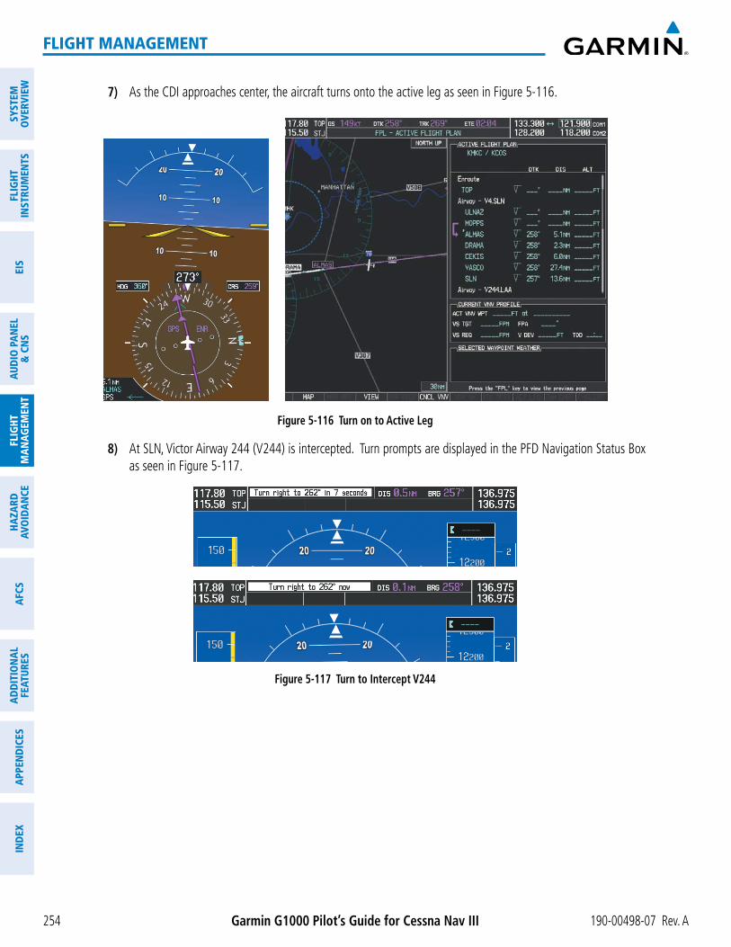
Garmin G1000 Pilot’s Guide for Cessna Nav III 190-00498-07 Rev. A254
FLIGHT MANAGEMENT
SYST
EMO
VERV
IEW
FLIG
HTIN
STRU
MEN
TSEI
SAU
DIO
PAN
EL&
CN
SFL
IGHT
MAN
AGEM
ENT
HAZA
RDAV
OID
ANCE
AFCS
ADD
ITIO
NAL
FEAT
URES
APPE
ND
ICES
IND
EX
7) As the CDI approaches center, the aircraft turns onto the active leg as seen in Figure 5-116.
Figure 5-116 Turn on to Active Leg
8) At SLN, Victor Airway 244 (V244) is intercepted. Turn prompts are displayed in the PFD Navigation Status Box as seen in Figure 5-117.
Figure 5-117 Turn to Intercept V244
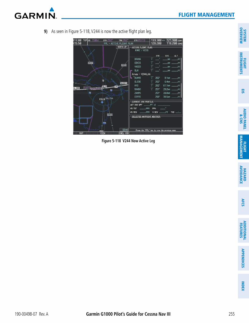
190-00498-07 Rev. A Garmin G1000 Pilot’s Guide for Cessna Nav III 255
FLIGHT MANAGEMENT
SYSTEMO
VERVIEWFLIG
HTIN
STRUMEN
TSEIS
AUDIO
PANEL
& CN
SFLIG
HTM
ANAG
EMEN
THAZARD
AVOIDAN
CEAFCS
ADD
ITION
ALFEATURES
APPEND
ICESIN
DEX
9) As seen in Figure 5-118, V244 is now the active flight plan leg.
Figure 5-118 V244 Now Active Leg

Garmin G1000 Pilot’s Guide for Cessna Nav III 190-00498-07 Rev. A256
FLIGHT MANAGEMENT
SYST
EMO
VERV
IEW
FLIG
HTIN
STRU
MEN
TSEI
SAU
DIO
PAN
EL&
CN
SFL
IGHT
MAN
AGEM
ENT
HAZA
RDAV
OID
ANCE
AFCS
ADD
ITIO
NAL
FEAT
URES
APPE
ND
ICES
IND
EX
10) At Lamar VOR (LAA) V263 is intercepted. See Figure 5-119.
Figure 5-119 HYS to LAA Leg Active
11) ATC grants clearance to proceed direct to the OPSHN intersection to begin the arrival procedure. ATC advises to expect an altitude of 10,000 feet at OPSHN.
a) Press the FMS Knob to activate the cursor.
b) Turn the large FMS Knob to select OPSHN in the flight plan list.
c) Press the Direct-to ( ) Key. The Direct-to Window is now displayed as shown in Figure 5-120.
Figure 5-120 Direct To OPSHN

190-00498-07 Rev. A Garmin G1000 Pilot’s Guide for Cessna Nav III 257
FLIGHT MANAGEMENT
SYSTEMO
VERVIEWFLIG
HTIN
STRUMEN
TSEIS
AUDIO
PANEL
& CN
SFLIG
HTM
ANAG
EMEN
THAZARD
AVOIDAN
CEAFCS
ADD
ITION
ALFEATURES
APPEND
ICESIN
DEX
d) Turn the large FMS Knob to place the cursor in the VNV altitude field as shown in Figure 5-121.
Figure 5-121 Enter VNV Altitude
e) An altitude of 10,000 feet is entered as requested by ATC.
f) Press the ENT Key. The cursor is now displayed in the VNV offset field as shown in Figure 5-122.
Figure 5-122 Enter VNV Offset Distance
g) Enter the offset, or distance from the waypoint at which to reach the selected altitude. In this case, three miles prior to OPSHN is entered. In other words, the G1000 gives vertical guidance so the aircraft arrives at an altitude of 10,000 feet three miles prior to OPSHN.

Garmin G1000 Pilot’s Guide for Cessna Nav III 190-00498-07 Rev. A258
FLIGHT MANAGEMENT
SYST
EMO
VERV
IEW
FLIG
HTIN
STRU
MEN
TSEI
SAU
DIO
PAN
EL&
CN
SFL
IGHT
MAN
AGEM
ENT
HAZA
RDAV
OID
ANCE
AFCS
ADD
ITIO
NAL
FEAT
URES
APPE
ND
ICES
IND
EX
h) Press the ENT Key twice to activate the direct-to. Note, in Figure 5-123, the magenta arrow indicating the direct-to OPSHN after the offset waypoint for OPSHN. The preceding offset waypoint indicates the offset distance and altitude that were previously entered. The remaining waypoints in the loaded arrival procedure have no database specified altitudes, therefore, dashes are displayed. Keep the CDI centered and maintain a track along the magenta line to OPSHN.
Note the Direct-to waypoint is within the loaded arrival procedure, therefore, phase of flight scaling for the CDI changes to Terminal Mode and is annunciated by displaying ‘TERM’ on the HSI.
NOTE: If the loaded arrival procedure has waypoints with altitude constraints retrieved from the database to be used as is, the altitude must be manually accepted by placing the cursor over the desired altitude, then pressing the ENT Key. The altitude is now displayed as light blue meaning it is used by the system to determine vertical speed and deviation guidance.
Figure 5-123 Direct-to Active
12) The aircraft is proceeding to OPSHN. The expected approach is the RNAV LPV approach to runway 35R, so it is selected.
a) Press the PROC Key to display the Procedures Window.

190-00498-07 Rev. A Garmin G1000 Pilot’s Guide for Cessna Nav III 259
FLIGHT MANAGEMENT
SYSTEMO
VERVIEWFLIG
HTIN
STRUMEN
TSEIS
AUDIO
PANEL
& CN
SFLIG
HTM
ANAG
EMEN
THAZARD
AVOIDAN
CEAFCS
ADD
ITION
ALFEATURES
APPEND
ICESIN
DEX
b) ‘SELECT APPROACH’ should be highlighted as shown in Figure 5-124.
Figure 5-124 Procedures Window
c) Press the ENT Key. A list of available approaches for the destination airport is displayed as in Figure 5-125.
Figure 5-125 List of Available Approaches
d) Turn either FMS Knob to select the LPV approach for 35R as shown in Figure 5-125.
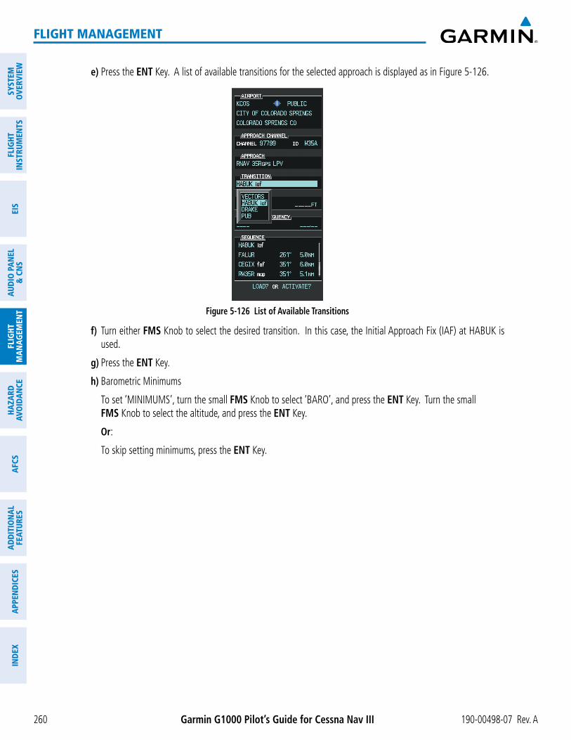
Garmin G1000 Pilot’s Guide for Cessna Nav III 190-00498-07 Rev. A260
FLIGHT MANAGEMENT
SYST
EMO
VERV
IEW
FLIG
HTIN
STRU
MEN
TSEI
SAU
DIO
PAN
EL&
CN
SFL
IGHT
MAN
AGEM
ENT
HAZA
RDAV
OID
ANCE
AFCS
ADD
ITIO
NAL
FEAT
URES
APPE
ND
ICES
IND
EX
e) Press the ENT Key. A list of available transitions for the selected approach is displayed as in Figure 5-126.
Figure 5-126 List of Available Transitions
f) Turn either FMS Knob to select the desired transition. In this case, the Initial Approach Fix (IAF) at HABUK is used.
g) Press the ENT Key.
h) Barometric Minimums
To set ‘MINIMUMS’, turn the small FMS Knob to select ‘BARO’, and press the ENT Key. Turn the small FMS Knob to select the altitude, and press the ENT Key.
Or:
To skip setting minimums, press the ENT Key.

190-00498-07 Rev. A Garmin G1000 Pilot’s Guide for Cessna Nav III 261
FLIGHT MANAGEMENT
SYSTEMO
VERVIEWFLIG
HTIN
STRUMEN
TSEIS
AUDIO
PANEL
& CN
SFLIG
HTM
ANAG
EMEN
THAZARD
AVOIDAN
CEAFCS
ADD
ITION
ALFEATURES
APPEND
ICESIN
DEX
Figure 5-127 Barometric Minimums Set
i) With ‘LOAD?’ highlighted, again press the ENT Key. The selected approach is added to the flight plan as seen in Figure 5-128.
Figure 5-128 Loaded Approach

Garmin G1000 Pilot’s Guide for Cessna Nav III 190-00498-07 Rev. A262
FLIGHT MANAGEMENT
SYST
EMO
VERV
IEW
FLIG
HTIN
STRU
MEN
TSEI
SAU
DIO
PAN
EL&
CN
SFL
IGHT
MAN
AGEM
ENT
HAZA
RDAV
OID
ANCE
AFCS
ADD
ITIO
NAL
FEAT
URES
APPE
ND
ICES
IND
EX
13) Note the altitude constraints associated with each of the approach waypoints as seen in Figure 5-129. These altitudes are loaded from the database and are displayed as light blue text, indicating these values are “designated” for use in computing vertical deviation guidance.
Note: To no longer use the displayed altitude for calculating vertical deviation guidance, perform the following:
a) Press the FMS Knob to activate the cursor.
b) Turn the small FMS Knob to highlight the desired altitude.
c) Press the CLR Key.
d) Press the FMS Knob to deactivate the cursor.
After making the altitude “non-designated”, it is displayed as white text.
Altitude constraint values associated with the Final Approach Fix (FAF) and waypoints beyond the FAF cannot be designated for vertical guidance. These altitude values are always displayed as white text, as in Figure 5-129. Vertical guidance from the FAF and on to the Missed Approach Point (MAP) is given using the SBAS GPS altitude source, therefore, the displayed altitude values are for reference only.
Figure 5-129 Vertical Guidance is Active to the FAF

190-00498-07 Rev. A Garmin G1000 Pilot’s Guide for Cessna Nav III 263
FLIGHT MANAGEMENT
SYSTEMO
VERVIEWFLIG
HTIN
STRUMEN
TSEIS
AUDIO
PANEL
& CN
SFLIG
HTM
ANAG
EMEN
THAZARD
AVOIDAN
CEAFCS
ADD
ITION
ALFEATURES
APPEND
ICESIN
DEX
14) As the aircraft approaches OPSHN, it may be desirable to adjust the speed, or steepness of the upcoming descent. The default Flight Path Angle (FPA) is -3.0 degrees and a required vertical speed is computed to maintain the -3.0 FPA. To change the vertical flight path, perform the following steps.
a) Press the VNV PROF Softkey to place the cursor in the target vertical speed field (VS TGT) as shown in Figure 5-130.
b) At this point, the descent vertical speed can be selected, or the FPA can be selected. Turn the large FMS Knob to select the desired selection field, then turn the small FMS Knob to enter the desired value.
Note the information now displayed in the ‘CURRENT VNV PROFILE’ box. Also, note the offset waypoint (orange box) and gray circle are now displayed on the map. The gray circle marks the Top of Descent (TOD). In this example, vertical guidance is provided at the TOD that results in a -3.0 degree FPA descent to an altitude of 10,000 feet upon reaching the offset waypoint.
Figure 5-130 Adjusting the Descent
c) Press the ENT Key.

Garmin G1000 Pilot’s Guide for Cessna Nav III 190-00498-07 Rev. A264
FLIGHT MANAGEMENT
SYST
EMO
VERV
IEW
FLIG
HTIN
STRU
MEN
TSEI
SAU
DIO
PAN
EL&
CN
SFL
IGHT
MAN
AGEM
ENT
HAZA
RDAV
OID
ANCE
AFCS
ADD
ITIO
NAL
FEAT
URES
APPE
ND
ICES
IND
EX
15) As seen in Figure 5-130, the aircraft is approaching TOD. Note the target vertical speed required to reach the selected altitude. The Vertical Deviation Indicator (VDI) and the Required Vertical Speed Indicator (RVSI) are now displayed on the PFD as shown in Figure 5-131. When the aircraft is within one minute of the TOD, it is annunciated as shown in Figure 5-132, and an aural alert ‘Vertical track’ will be heard.
Figure 5-131 Approaching Top of Descent (TOD)
Figure 5-132 VDI & RVSI Upon Reaching Top of Descent (TOD)
Required Vertical Speed Indicator(RVSI)
Vertical Deviation Indicator (VDI)
Target Altitude

190-00498-07 Rev. A Garmin G1000 Pilot’s Guide for Cessna Nav III 265
FLIGHT MANAGEMENT
SYSTEMO
VERVIEWFLIG
HTIN
STRUMEN
TSEIS
AUDIO
PANEL
& CN
SFLIG
HTM
ANAG
EMEN
THAZARD
AVOIDAN
CEAFCS
ADD
ITION
ALFEATURES
APPEND
ICESIN
DEX
16) Upon reaching TOD, a descent vertical speed is established by placing the VSI pointer in line with the RVSI as shown in Figure 5-133.
Figure 5-133 VDI & RVSI Showing Correctly Established Descent
Align Actual Vertical Speed withRequired Vertical Speed
Keep Vertical Deviation Indicator Centered
17) When the aircraft is one minute from the bottom of descent (BOD) it is annunciated as shown in Figure 5-134. Upon reaching the offset waypoint for OPSHN, the aircraft is at 10,000 feet.
Figure 5-134 Approaching Bottom of Descent (BOD) at OPSHN Offset Waypoint

Garmin G1000 Pilot’s Guide for Cessna Nav III 190-00498-07 Rev. A266
FLIGHT MANAGEMENT
SYST
EMO
VERV
IEW
FLIG
HTIN
STRU
MEN
TSEI
SAU
DIO
PAN
EL&
CN
SFL
IGHT
MAN
AGEM
ENT
HAZA
RDAV
OID
ANCE
AFCS
ADD
ITIO
NAL
FEAT
URES
APPE
ND
ICES
IND
EX
18) The aircraft is approaching OPSHN. The upcoming turn and next heading are annunciated at the top left of the PFD as seen in Figure 5-135. Initiate the turn and maneuver the aircraft on a track through the turn radius to intercept the magenta line for the OPSHN to FSHER leg and center the CDI.
Figure 5-135 Turn to intercept OPSHN to FSHER Leg

190-00498-07 Rev. A Garmin G1000 Pilot’s Guide for Cessna Nav III 267
FLIGHT MANAGEMENT
SYSTEMO
VERVIEWFLIG
HTIN
STRUMEN
TSEIS
AUDIO
PANEL
& CN
SFLIG
HTM
ANAG
EMEN
THAZARD
AVOIDAN
CEAFCS
ADD
ITION
ALFEATURES
APPEND
ICESIN
DEX
19) After passing OPSHN, the next leg of the arrival turns magenta as shown in Figure 5-136. The magenta arrow in the flight plan list now indicates the OPSHN to FSHER leg of the arrival procedure is now active.
Figure 5-136 Tracking the OPSHN to FSHER Leg
20) The flight continues through the arrival procedure to PYNON (see Figure 5-137). At a point 31 nm from the destination airport, the phase of flight scaling for the CDI changes to Terminal Mode and is annunciated by displaying ‘TERM’ on the HSI.
A descent to HABUK is in the next leg. Note the TOD point on the map. Annunciations for the upcoming turn and descent, as well as the VDI and RVSI, appear on the PFD as the flight progresses.
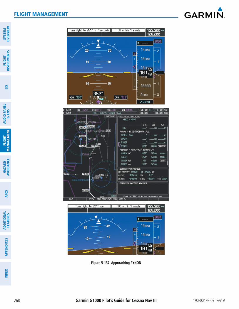
Garmin G1000 Pilot’s Guide for Cessna Nav III 190-00498-07 Rev. A268
FLIGHT MANAGEMENT
SYST
EMO
VERV
IEW
FLIG
HTIN
STRU
MEN
TSEI
SAU
DIO
PAN
EL&
CN
SFL
IGHT
MAN
AGEM
ENT
HAZA
RDAV
OID
ANCE
AFCS
ADD
ITIO
NAL
FEAT
URES
APPE
ND
ICES
IND
EX
Figure 5-137 Approaching PYNON

190-00498-07 Rev. A Garmin G1000 Pilot’s Guide for Cessna Nav III 269
FLIGHT MANAGEMENT
SYSTEMO
VERVIEWFLIG
HTIN
STRUMEN
TSEIS
AUDIO
PANEL
& CN
SFLIG
HTM
ANAG
EMEN
THAZARD
AVOIDAN
CEAFCS
ADD
ITION
ALFEATURES
APPEND
ICESIN
DEX
21) Upon passing PYNON the approach procedure automatically becomes active. The approach may be activated at any point to proceed directly to the IAF. In this example, the aircraft has progressed through the final waypoint of the arrival and the flight plan has automatically sequenced to the IAF as the active leg, activating the approach procedure (see Figure 5-138).
Figure 5-138 Approach is Now Active
Note: To manually activate the approach procedure, perform the following steps:
a) Press the PROC Key.
b) Turn the large FMS Knob to highlight ‘ACTIVATE APPROACH’ as shown in Figure 5-139.
c) Press the ENT Key to activate the approach.
Figure 5-139 Manually Activate Approach

Garmin G1000 Pilot’s Guide for Cessna Nav III 190-00498-07 Rev. A270
FLIGHT MANAGEMENT
SYST
EMO
VERV
IEW
FLIG
HTIN
STRU
MEN
TSEI
SAU
DIO
PAN
EL&
CN
SFL
IGHT
MAN
AGEM
ENT
HAZA
RDAV
OID
ANCE
AFCS
ADD
ITIO
NAL
FEAT
URES
APPE
ND
ICES
IND
EX
22) The IAF is the next waypoint. At the TOD, establish a descent vertical speed as previously discussed in Step 16. The aircraft altitude is 9,000 feet upon reaching HABUK.
Figure 5-140 Descending Turn to the Initial Approach Fix (IAF)

190-00498-07 Rev. A Garmin G1000 Pilot’s Guide for Cessna Nav III 271
FLIGHT MANAGEMENT
SYSTEMO
VERVIEWFLIG
HTIN
STRUMEN
TSEIS
AUDIO
PANEL
& CN
SFLIG
HTM
ANAG
EMEN
THAZARD
AVOIDAN
CEAFCS
ADD
ITION
ALFEATURES
APPEND
ICESIN
DEX
23) After crossing FALUR the next waypoint is the FAF. The flight phase changes to LPV on the HSI indicating the current phase of flight is in Approach Mode and the approach type is LPV. CDI scaling changes accordingly and is used much like a localizer when flying an ILS approach. The RVSI is no longer displayed and the VDI changes to the Glidepath Indicator (as shown in Figure 5-141) when the final approach course becomes active.
Figure 5-141 Descending to the FAF
The descent continues through the FAF (CEGIX) using the Glidepath Indicator, as one would use a glideslope indicator, to obtain an altitude “AT” 7,800 feet at the FAF. Note the altitude restriction lines over and under (At) the altitude in the ‘ALT’ field in Figure 5-141.
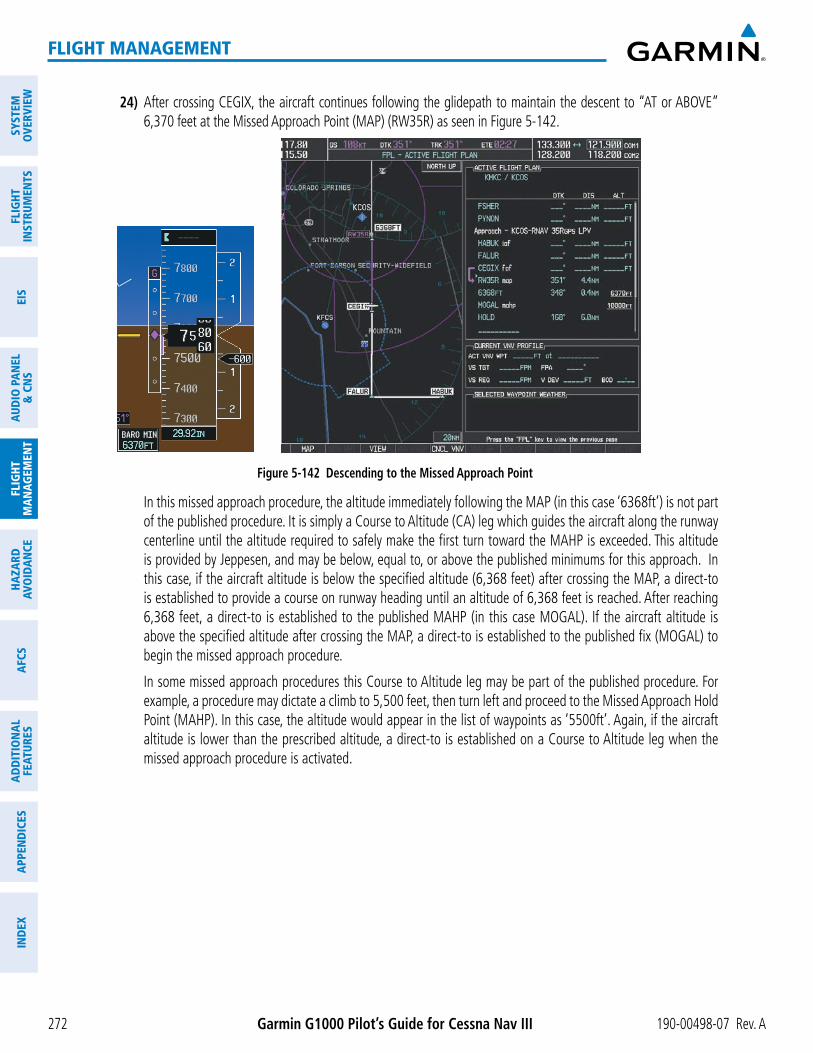
Garmin G1000 Pilot’s Guide for Cessna Nav III 190-00498-07 Rev. A272
FLIGHT MANAGEMENT
SYST
EMO
VERV
IEW
FLIG
HTIN
STRU
MEN
TSEI
SAU
DIO
PAN
EL&
CN
SFL
IGHT
MAN
AGEM
ENT
HAZA
RDAV
OID
ANCE
AFCS
ADD
ITIO
NAL
FEAT
URES
APPE
ND
ICES
IND
EX
24) After crossing CEGIX, the aircraft continues following the glidepath to maintain the descent to “AT or ABOVE” 6,370 feet at the Missed Approach Point (MAP) (RW35R) as seen in Figure 5-142.
Figure 5-142 Descending to the Missed Approach Point
In this missed approach procedure, the altitude immediately following the MAP (in this case ‘6368ft’) is not part of the published procedure. It is simply a Course to Altitude (CA) leg which guides the aircraft along the runway centerline until the altitude required to safely make the first turn toward the MAHP is exceeded. This altitude is provided by Jeppesen, and may be below, equal to, or above the published minimums for this approach. In this case, if the aircraft altitude is below the specified altitude (6,368 feet) after crossing the MAP, a direct-to is established to provide a course on runway heading until an altitude of 6,368 feet is reached. After reaching 6,368 feet, a direct-to is established to the published MAHP (in this case MOGAL). If the aircraft altitude is above the specified altitude after crossing the MAP, a direct-to is established to the published fix (MOGAL) to begin the missed approach procedure.
In some missed approach procedures this Course to Altitude leg may be part of the published procedure. For example, a procedure may dictate a climb to 5,500 feet, then turn left and proceed to the Missed Approach Hold Point (MAHP). In this case, the altitude would appear in the list of waypoints as ‘5500ft’. Again, if the aircraft altitude is lower than the prescribed altitude, a direct-to is established on a Course to Altitude leg when the missed approach procedure is activated.
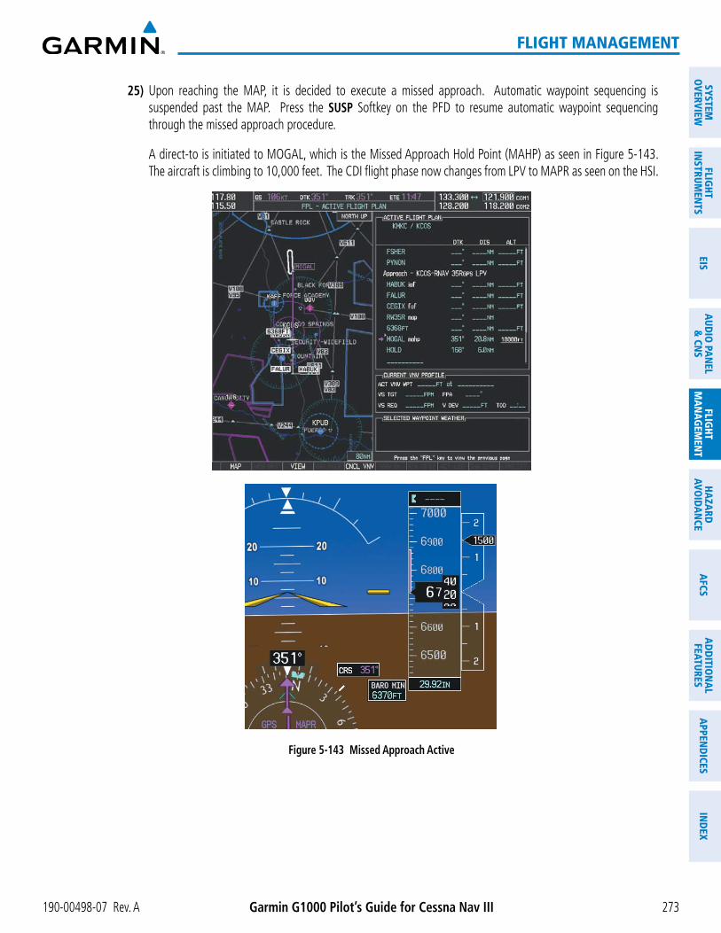
190-00498-07 Rev. A Garmin G1000 Pilot’s Guide for Cessna Nav III 273
FLIGHT MANAGEMENT
SYSTEMO
VERVIEWFLIG
HTIN
STRUMEN
TSEIS
AUDIO
PANEL
& CN
SFLIG
HTM
ANAG
EMEN
THAZARD
AVOIDAN
CEAFCS
ADD
ITION
ALFEATURES
APPEND
ICESIN
DEX
25) Upon reaching the MAP, it is decided to execute a missed approach. Automatic waypoint sequencing is suspended past the MAP. Press the SUSP Softkey on the PFD to resume automatic waypoint sequencing through the missed approach procedure.
A direct-to is initiated to MOGAL, which is the Missed Approach Hold Point (MAHP) as seen in Figure 5-143. The aircraft is climbing to 10,000 feet. The CDI flight phase now changes from LPV to MAPR as seen on the HSI.
Figure 5-143 Missed Approach Active

Garmin G1000 Pilot’s Guide for Cessna Nav III 190-00498-07 Rev. A274
FLIGHT MANAGEMENT
SYST
EMO
VERV
IEW
FLIG
HTIN
STRU
MEN
TSEI
SAU
DIO
PAN
EL&
CN
SFL
IGHT
MAN
AGEM
ENT
HAZA
RDAV
OID
ANCE
AFCS
ADD
ITIO
NAL
FEAT
URES
APPE
ND
ICES
IND
EX
26) The aircraft continues climbing to “AT or ABOVE” 10,000 feet at MOGAL. A holding pattern is established at the MAHP (MOGAL) as shown in Figure 5-144.
Figure 5-144 Establishing the Holding Pattern
27) The aircraft maintains 10,000 feet while following the magenta line through the hold as in Figure 5-145.
Figure 5-145 Hold Established

190-00498-07 Rev. A Garmin G1000 Pilot’s Guide for Cessna Nav III 275
FLIGHT MANAGEMENT
SYSTEMO
VERVIEWFLIG
HTIN
STRUMEN
TSEIS
AUDIO
PANEL
& CN
SFLIG
HTM
ANAG
EMEN
THAZARD
AVOIDAN
CEAFCS
ADD
ITION
ALFEATURES
APPEND
ICESIN
DEX
5.12 ABNORMAL OPERATION
NOTE: Dead Reckoning Mode only functions in Enroute (ENR) or Oceanic (OCN) phase of flight. In all other phases, an invalid GPS solution produces a “NO GPS POSITION” annunciation on the map and the G1000 stops using GPS.
While in Enroute or Oceanic phase of flight, if the G1000 detects an invalid GPS solution or is unable to calculate a GPS position, the system automatically reverts to Dead Reckoning (DR) Mode. In DR Mode, the G1000 uses its last-known position combined with continuously updated airspeed and heading data (when available) to calculate and display the aircraft’s current estimated position.
It is important to note that estimated navigation data supplied by the G1000 in DR Mode may become increasingly unreliable and must not be used as a sole means of navigation. If while in DR Mode airspeed and/or heading data is also lost or not available, the DR function may not be capable of accurately tracking estimated position and,
position information displayed by the G1000 through DR while there is no heading and/or airspeed data available should not be used for navigation.
DR Mode is inherently less accurate than the standard GPS/SBAS Mode due to the lack of satellite measurements needed to determine a position. Changes in wind speed and/or wind direction compound the relative inaccuracy
awareness until GPS-derived position data is restored.
slightly above and to the right of the aircraft symbol on the CDI as shown in Figure 5-146. The CDI deviation bar remains, but is removed from the display after 20 minutes in DR Mode. The autopilot will remain coupled
message appears on the PFD. Normal navigation using GPS/SBAS source data resumes automatically once a valid GPS solution is restored.
As a result of operating in DR Mode, all GPS-derived data is computed based upon an estimated position and is displayed as yellow text on the display to denote degraded navigation source information as shown in Figure 5-146.
Also, while the G1000 is in DR Mode, the autopilot will remain coupled to GPS for up to 20 minutes. TAWS, Terrain-SVS, and Terrain Proximity are disabled. Additionally, the accuracy of all nearest information (airports,
accuracy.
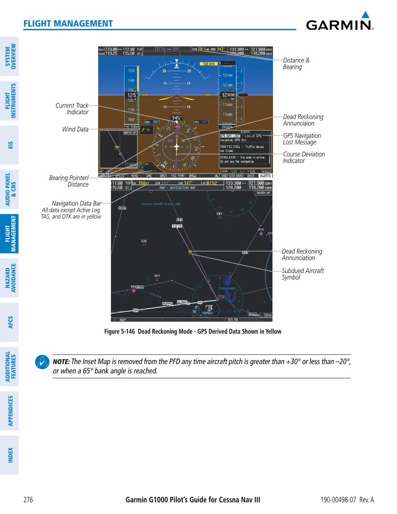
Garmin G1000 Pilot’s Guide for Cessna Nav III 190-00498-07 Rev. A276
FLIGHT MANAGEMENT
SYST
EMO
VERV
IEW
FLIG
HTIN
STRU
MEN
TSEI
SAU
DIO
PAN
EL&
CN
SFL
IGHT
MAN
AGEM
ENT
HAZA
RDAV
OID
ANCE
AFCS
ADD
ITIO
NAL
FEAT
URES
APPE
ND
ICES
IND
EX
Figure 5-146 Dead Reckoning Mode - GPS Derived Data Shown in Yellow
Distance &Bearing
GPS Navigation Lost Message
Dead Reckoning Annunciation
Subdued Aircraft Symbol
Navigation Data BarAll data except Active Leg, TAS, and DTK are in yellow
Dead Reckoning Annunciaion
Wind Data
Bearing Pointer/Distance
Current Track Indicator
Course Deviation Indicator
NOTE: The Inset Map is removed from the PFD any time aircraft pitch is greater than +30° or less than –20°, or when a 65° bank angle is reached.